WO2019069436A1 - 監視装置、監視システムおよび監視方法 - Google Patents
監視装置、監視システムおよび監視方法 Download PDFInfo
- Publication number
- WO2019069436A1 WO2019069436A1 PCT/JP2017/036381 JP2017036381W WO2019069436A1 WO 2019069436 A1 WO2019069436 A1 WO 2019069436A1 JP 2017036381 W JP2017036381 W JP 2017036381W WO 2019069436 A1 WO2019069436 A1 WO 2019069436A1
- Authority
- WO
- WIPO (PCT)
- Prior art keywords
- data
- information
- dimensional coordinates
- monitoring
- client
- Prior art date
Links
- 238000012806 monitoring device Methods 0.000 title claims abstract description 18
- 238000012544 monitoring process Methods 0.000 title claims description 40
- 238000000034 method Methods 0.000 title claims description 18
- 238000004519 manufacturing process Methods 0.000 claims description 38
- 230000033001 locomotion Effects 0.000 claims description 14
- 238000012937 correction Methods 0.000 claims description 10
- 125000000174 L-prolyl group Chemical group [H]N1C([H])([H])C([H])([H])C([H])([H])[C@@]1([H])C(*)=O 0.000 claims description 2
- 238000010586 diagram Methods 0.000 description 31
- 238000012545 processing Methods 0.000 description 15
- 230000006870 function Effects 0.000 description 11
- 230000008569 process Effects 0.000 description 5
- 101100277637 Mus musculus Dffa gene Proteins 0.000 description 4
- 238000004088 simulation Methods 0.000 description 4
- 238000013024 troubleshooting Methods 0.000 description 4
- 238000009434 installation Methods 0.000 description 3
- 238000012423 maintenance Methods 0.000 description 3
- 238000012546 transfer Methods 0.000 description 3
- 238000004891 communication Methods 0.000 description 2
- 230000008901 benefit Effects 0.000 description 1
- 230000008859 change Effects 0.000 description 1
- 239000003086 colorant Substances 0.000 description 1
- 238000011960 computer-aided design Methods 0.000 description 1
- 230000000694 effects Effects 0.000 description 1
- 239000000284 extract Substances 0.000 description 1
- 230000002452 interceptive effect Effects 0.000 description 1
- 238000012986 modification Methods 0.000 description 1
- 230000004048 modification Effects 0.000 description 1
- 230000009467 reduction Effects 0.000 description 1
- 230000004044 response Effects 0.000 description 1
- 239000004065 semiconductor Substances 0.000 description 1
Images


Classifications
-
- G—PHYSICS
- G05—CONTROLLING; REGULATING
- G05B—CONTROL OR REGULATING SYSTEMS IN GENERAL; FUNCTIONAL ELEMENTS OF SUCH SYSTEMS; MONITORING OR TESTING ARRANGEMENTS FOR SUCH SYSTEMS OR ELEMENTS
- G05B19/00—Programme-control systems
- G05B19/02—Programme-control systems electric
- G05B19/04—Programme control other than numerical control, i.e. in sequence controllers or logic controllers
- G05B19/042—Programme control other than numerical control, i.e. in sequence controllers or logic controllers using digital processors
-
- G—PHYSICS
- G05—CONTROLLING; REGULATING
- G05B—CONTROL OR REGULATING SYSTEMS IN GENERAL; FUNCTIONAL ELEMENTS OF SUCH SYSTEMS; MONITORING OR TESTING ARRANGEMENTS FOR SUCH SYSTEMS OR ELEMENTS
- G05B19/00—Programme-control systems
- G05B19/02—Programme-control systems electric
- G05B19/04—Programme control other than numerical control, i.e. in sequence controllers or logic controllers
- G05B19/05—Programmable logic controllers, e.g. simulating logic interconnections of signals according to ladder diagrams or function charts
- G05B19/058—Safety, monitoring
-
- G—PHYSICS
- G05—CONTROLLING; REGULATING
- G05B—CONTROL OR REGULATING SYSTEMS IN GENERAL; FUNCTIONAL ELEMENTS OF SUCH SYSTEMS; MONITORING OR TESTING ARRANGEMENTS FOR SUCH SYSTEMS OR ELEMENTS
- G05B19/00—Programme-control systems
- G05B19/02—Programme-control systems electric
- G05B19/418—Total factory control, i.e. centrally controlling a plurality of machines, e.g. direct or distributed numerical control [DNC], flexible manufacturing systems [FMS], integrated manufacturing systems [IMS] or computer integrated manufacturing [CIM]
- G05B19/41885—Total factory control, i.e. centrally controlling a plurality of machines, e.g. direct or distributed numerical control [DNC], flexible manufacturing systems [FMS], integrated manufacturing systems [IMS] or computer integrated manufacturing [CIM] characterised by modeling, simulation of the manufacturing system
-
- G—PHYSICS
- G05—CONTROLLING; REGULATING
- G05B—CONTROL OR REGULATING SYSTEMS IN GENERAL; FUNCTIONAL ELEMENTS OF SUCH SYSTEMS; MONITORING OR TESTING ARRANGEMENTS FOR SUCH SYSTEMS OR ELEMENTS
- G05B23/00—Testing or monitoring of control systems or parts thereof
- G05B23/02—Electric testing or monitoring
-
- B—PERFORMING OPERATIONS; TRANSPORTING
- B25—HAND TOOLS; PORTABLE POWER-DRIVEN TOOLS; MANIPULATORS
- B25J—MANIPULATORS; CHAMBERS PROVIDED WITH MANIPULATION DEVICES
- B25J9/00—Programme-controlled manipulators
- B25J9/16—Programme controls
- B25J9/1656—Programme controls characterised by programming, planning systems for manipulators
- B25J9/1671—Programme controls characterised by programming, planning systems for manipulators characterised by simulation, either to verify existing program or to create and verify new program, CAD/CAM oriented, graphic oriented programming systems
-
- G—PHYSICS
- G05—CONTROLLING; REGULATING
- G05B—CONTROL OR REGULATING SYSTEMS IN GENERAL; FUNCTIONAL ELEMENTS OF SUCH SYSTEMS; MONITORING OR TESTING ARRANGEMENTS FOR SUCH SYSTEMS OR ELEMENTS
- G05B19/00—Programme-control systems
- G05B19/02—Programme-control systems electric
- G05B19/418—Total factory control, i.e. centrally controlling a plurality of machines, e.g. direct or distributed numerical control [DNC], flexible manufacturing systems [FMS], integrated manufacturing systems [IMS] or computer integrated manufacturing [CIM]
- G05B19/41815—Total factory control, i.e. centrally controlling a plurality of machines, e.g. direct or distributed numerical control [DNC], flexible manufacturing systems [FMS], integrated manufacturing systems [IMS] or computer integrated manufacturing [CIM] characterised by the cooperation between machine tools, manipulators and conveyor or other workpiece supply system, workcell
- G05B19/41825—Total factory control, i.e. centrally controlling a plurality of machines, e.g. direct or distributed numerical control [DNC], flexible manufacturing systems [FMS], integrated manufacturing systems [IMS] or computer integrated manufacturing [CIM] characterised by the cooperation between machine tools, manipulators and conveyor or other workpiece supply system, workcell machine tools and manipulators only, machining centre
-
- G—PHYSICS
- G05—CONTROLLING; REGULATING
- G05B—CONTROL OR REGULATING SYSTEMS IN GENERAL; FUNCTIONAL ELEMENTS OF SUCH SYSTEMS; MONITORING OR TESTING ARRANGEMENTS FOR SUCH SYSTEMS OR ELEMENTS
- G05B2219/00—Program-control systems
- G05B2219/30—Nc systems
- G05B2219/40—Robotics, robotics mapping to robotics vision
- G05B2219/40311—Real time simulation
-
- Y—GENERAL TAGGING OF NEW TECHNOLOGICAL DEVELOPMENTS; GENERAL TAGGING OF CROSS-SECTIONAL TECHNOLOGIES SPANNING OVER SEVERAL SECTIONS OF THE IPC; TECHNICAL SUBJECTS COVERED BY FORMER USPC CROSS-REFERENCE ART COLLECTIONS [XRACs] AND DIGESTS
- Y02—TECHNOLOGIES OR APPLICATIONS FOR MITIGATION OR ADAPTATION AGAINST CLIMATE CHANGE
- Y02P—CLIMATE CHANGE MITIGATION TECHNOLOGIES IN THE PRODUCTION OR PROCESSING OF GOODS
- Y02P90/00—Enabling technologies with a potential contribution to greenhouse gas [GHG] emissions mitigation
- Y02P90/02—Total factory control, e.g. smart factories, flexible manufacturing systems [FMS] or integrated manufacturing systems [IMS]
Definitions
- the present invention relates to a monitoring device, a monitoring system and a monitoring method for maintenance of factory equipment.
- the monitoring apparatus consisting of the conventional surveillance camera is recording from one direction of the surveillance camera, it is impossible to reproduce the detailed operation of the manufacturing site which becomes the blind spot of the surveillance camera, and the manufacturing apparatus such as a robot There was a problem that it took time to identify the cause when trouble occurred or it was difficult to identify the cause. In addition, even if a trouble is notified from the monitoring device, in order to solve the trouble, the user needs to go to the manufacturing site, reproduce and confirm the trouble, and identify the cause.
- Patent Document 1 two robot control devices and one monitor device are connected, and the operation states of the two robots are drawn in real time on the display screen of one monitor device, whereby the robot operation is performed.
- the monitoring device periodically collects the current value of the joint angle of the robot from the joint angle server on the robot control device via the communication network, and updates the drawing data of the robot.
- Patent Document 1 aims to monitor the operation state of the robot, and only the current value of the joint angle of the robot is collected to execute the simulation. Therefore, although it is possible to reconfirm the robot simulation using the current value of the joint angle, it is possible to realistically simulate the trouble under the facility operating condition such as the collision between the transported object on the belt conveyor and the robot. No, I could not use the simulation to take measures against the problem.
- the present invention has been made in view of the above, and it is an object of the present invention to obtain a monitoring device that makes it possible to simulate the operating condition of factory equipment including a manufacturing device.
- the present invention acquires information of three-dimensional coordinates at each time indicating the operation status of factory equipment.
- the present invention is a locus that describes a command on how to combine information of an image showing the operation status of factory equipment with three-dimensional coordinates based on the three-dimensional coordinates for each time and the received reproduction instruction.
- a trajectory data generation unit for generating data is provided.
- the monitoring apparatus concerning this invention has an effect that it becomes possible to simulate the working condition of the factory installation containing a manufacturing apparatus.
- Block diagram showing the configuration of factory equipment according to the first embodiment of the present invention Block diagram showing the detailed configuration of the monitoring system according to the first embodiment Flowchart for explaining the operation of the logging unit according to the first embodiment Flow chart for explaining processing of client and server according to the first embodiment A diagram for explaining “real time reproduction” according to the first embodiment A diagram for explaining “normal reproduction” according to the first embodiment A diagram for explaining “reverse reproduction” according to the first embodiment Diagram for explaining the flow of client and server processing according to the first embodiment Another diagram for explaining the flow of client and server processing according to the first embodiment Diagram showing the configuration of a script according to the first embodiment A diagram showing the configuration of a script related file according to the first embodiment Diagram for explaining execution of “normal playback” according to the first embodiment Diagram for explaining execution of “reverse reproduction” according to the first embodiment FIG.
- FIG. 6 is a diagram showing a screen of a display unit during execution of “normal playback” according to the first embodiment.
- Flow chart for explaining processing of client and server when trouble occurs in the first embodiment Diagram for explaining the flow of client and server processing when a problem occurs in Embodiment 1
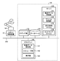
- the factory facility 1 further includes a sensor 180 that detects the position of the workpiece 170, a sensor 181 that detects the temperature of the robot 161, and a sensor 182 that detects the temperature of the robot 162.
- the temperature of each of the robots 161 and 162 is the temperature of each axis corresponding to each joint of the robot arms constituting the robots 161 and 162.
- the robot control devices 151 and 152, the sensors 180, 181 and 182, and the belt conveyor 190 are connected to the network 200.
- the network 200 may be wired or wireless.
- the factory installation 1 is provided with a monitoring system 100 that monitors the states of the robots 161 and 162 and the work 170.
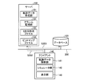
- the monitoring system 100 includes a logging unit 110 having a logging function, a database 120 held in a storage device, a server 130 that is a monitoring device, and a client device 140 that is a client device that displays moving images that simulate the operation of the factory facility 1. And.
- the client 140 simulates and displays the operation of the three-dimensional shape of the factory facility 1.
- the logging unit 110, the database 120, the server 130 and the client 140 are connected to the network 200.
- the logging unit 110, the server 130 and the client 140 are realized by a computer.
- the logging unit 110 and the server 130 may be realized by separate computers, but one computer may realize the functions of both.
- the client 140 simulates and displays the operation of the three-dimensional shape of the manufacturing site in the plant facility 1 based on the data acquired from the server 130.
- the logging unit 110 acquires information of three-dimensional coordinates for each time indicating the operation status of the factory facility 1 including the manufacturing apparatus.
- the factory equipment 1 includes the belt conveyor 190 in addition to the robots 161 and 162, and the operation status of the factory equipment 1 also includes the situation of the workpiece 170. Therefore, specifically, the logging unit 110 collects data such as the position and angle of each axis of the robots 161 and 162, the speed of the belt conveyor 190, the position of the workpiece 170, and the time information at a constant cycle.
- the logging unit 110 transfers the collected data to the database 120 via the network 200 and stores the data in the database 120.
- the server 130 accesses the database 120 to acquire necessary data.
- the client 140 requests the server 130 for data necessary for the reproduction operation of the manufacturing apparatus and the manufacturing line.
- FIG. 2 is a block diagram showing the detailed configuration of the monitoring system 100 according to the first embodiment.
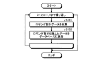
- FIG. 3 is a flowchart for explaining the operation of the logging unit 110 according to the first embodiment. Note that FIG. 2 omits some of the components of FIG. 1 for the sake of simplicity.
- the operation period of the plant facility 1 is N cycles when the cycle in which the logging unit 110 collects information is taken as a unit.
- the logging unit 110 collects data from the robot control devices 151 and 152, the belt conveyor 190, and the sensors 180, 181 and 182 (step S101).
- the logging unit 110 is a position and an angle of each axis of the robot 161, 162 from the robot control device 151, 152, a speed of the belt conveyor 190 from the belt conveyor 190, a position of the work 170 from the sensor 180,
- Data such as the temperatures of the robots 161 and 162 from the sensors 181 and 182 are collected via the network 200 together with time information.
- the data collected by the logging unit 110 via the network 200 may include the speed of movement of each axis of the robots 161 and 162, the temperature of the manufacturing line and the manufacturing site where the manufacturing apparatus is installed. .
- the logging unit 110 saves the collected data in the database 120 for each time (step S102).
- the logging unit 110 acquires the position and angle of each axis of the robots 161 and 162, the speed of the belt conveyor 190, the position of the workpiece 170 and the temperature of the robots 161 and 162 for each fixed cycle, and the database together with time information It can be stored at 120. If the absolute value of the difference between the value of the data collected at a certain timing and the value collected one cycle before the relevant timing is larger than a predetermined value, the logging unit 110 uses the data collected at the relevant timing. Determines that noise is superimposed, the data is discarded and the data is not stored in the database 120.
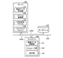
- the server 130 generates a locus data generation unit 131 that generates locus data relating to a locus of the three-dimensional shape of the plant facility 1 in response to a request from the client 140, and an alarm monitoring unit 132 that acquires alarm information and notifies the client 140. And a three-dimensional shape file 133 based on the information acquired from the database 120, and a bitmap file 134 which is image data.
- the locus data creation unit 131 creates a script or script file including locus data. As described later, a script is a data file in which data other than trajectory data is also described, but only trajectory data is described in the script file.
- the three-dimensional shape file 133 is a file having information of three-dimensional coordinates indicating the operating status of the factory equipment 1 including the manufacturing apparatus. Specifically, the three-dimensional shape file 133 is data including the data of the position of each axis of the robots 161 and 162 in the three-dimensional space and the data of the position of the workpiece 170 on the belt conveyor 190 in the three-dimensional space. is there.
- the three-dimensional shape file 133 contains information of three-dimensional coordinates of a skeleton or a point group to be an outline for displaying the robots 161 and 162 and the workpiece 170 in three-dimensional space.
- the data of the three-dimensional coordinates of each axis of the robots 161 and 162 is acquired by the logging unit 110 from the control program of the robots 161 and 162 possessed by the robot control devices 151 and 152 and fixed in the database 120 It is stored with the time information in a cycle. Further, the data of the three-dimensional coordinates of the workpiece 170 on the belt conveyor 190 is acquired by the logging unit 110 from the sensor 180 or the belt conveyor 190 and stored in the database 120 along with the time at a constant cycle. The client 140 accesses the database 120, and based on the data stored in the database 120, creates the three-dimensional shape file 133 for each time and saves it in its own storage device.
- the file format of the three-dimensional shape file 133 conforms to the data format of AutoCAD (registered trademark), SOLIDWORKS (registered trademark) or iCAD (registered trademark)
- the three-dimensional shape file 133 is AutoCAD (registered trademark), SOLIDWORKS (registered trademark) It is readable by registered trademark) or iCAD (registered trademark).
- the file format of the three-dimensional shape file 133 is three-dimensional file format Parasolid, Initial Graphics Exchange Specification (IGES), STEP, Standard Triangulated Language (STEP), VPS, Virtual Reality Modeling Language (VRML), CATIA V5 ( It may be a file format such as Computer graphics Aided Three dimensional Interactive Application V5), Pro / E, NX, I-deas or JT. Also, the file format of the three-dimensional shape file 133 is not limited to the existing format as described above, and may be a unique or new file format.
- the bit map file 134 is a file having image information indicating the operating status of the factory facility 1 including the manufacturing apparatus. Specifically, the bit map file 134 is a robot 161, 162 and a work required to draw the robot 161, 162 and the work 170 in the three-dimensional space by adding to the skeleton or outline indicated by the three-dimensional shape file 133. It is a file which shows the information of 170 images. That is, the bitmap file 134 is information of an image to be pasted on the three-dimensional space along the point group indicated by the three-dimensional shape file 133.
- the file format of the bitmap file 134 conforms to the data format of AutoCAD (registered trademark), SOLIDWORKS (registered trademark) or iCAD (registered trademark)
- the bitmap file 134 is AutoCAD (registered trademark), SOLIDWORKS (registered trademark) Or iCAD (registered trademark). Therefore, the file format of the bitmap file 134 may be a file format such as DXF (Drawing Exchange Format), DWG, ME-10, IGES, MicroCADAM drawing, DMNDOS, MCD or BMI.
- DWG is a standard file format of AutoCAD (registered trademark).
- the file format of the bitmap file 134 is not limited to the existing format as described above, and may be a unique or new file format.
- the client 140 simulates the operation of the three-dimensional shape of the factory facility 1 based on the interpretation result of the locus data interpretation unit 141 that interprets the locus data included in the script or script file acquired from the server 130 and the locus data interpretation unit 141.
- a simulator unit 142 to be executed and a display unit 143 for displaying the result of the operation simulation of the three-dimensional shape by the simulator unit 142 are provided.
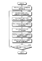
- FIG. 4 is a flowchart illustrating processing of the client 140 and the server 130 according to the first embodiment.
- FIG. 5 is a diagram for explaining “real time reproduction” according to the first embodiment.
- FIG. 6 is a diagram for explaining “normal reproduction” according to the first embodiment.
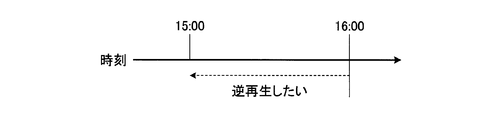
- FIG. 7 is a diagram for explaining “reverse reproduction” according to the first embodiment.
- FIG. 8 is a diagram for explaining the process flow of the client 140 and the server 130 according to the first embodiment.
- FIG. 9 is another diagram illustrating the process flow of the client 140 and the server 130 according to the first embodiment.
- FIG. 10 is a diagram showing the configuration of a script according to the first embodiment.
- FIG. 11 is a diagram showing the configuration of a script related file according to the first embodiment.
- FIG. 12 is a diagram for explaining the execution of the “normal reproduction” according to the first embodiment.
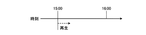
- FIG. 13 is a diagram for explaining the execution of “reverse reproduction” according to the first embodiment.
- FIG. 14 is a diagram of a screen of the display unit during execution of “normal playback” according to the first embodiment.
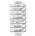
- the user instructs either playback or reverse playback, and the input device of the client 140 receives the user's instruction (FIG. 4, step S201). Specifically, the user instructs one of “real-time reproduction”, “normal reproduction”, and “reverse reproduction”, and the input device of the client 140 receives any instruction.
- both the reverse playback times are specified . If the current time and the reverse playback time are both 16:00, the user desires reverse playback as shown in FIG.
- the client 140 requests the server 130 to transmit necessary data (FIG. 4, FIG. 8, step S202).
- the client 140 notifies the server 130 of the “real-time playback”, “normal playback” or “reverse playback” instruction accepted in step S 201 and the period determined according to the instruction to the server 130,
- the server 130 is requested to transmit data for the period.
- the period determined in accordance with the instruction is a unit of time of data which is a group of data transfer in “real time reproduction”, “normal reproduction” or “reverse reproduction”.
- the server 130 may initially hold a period determined in accordance with “real time reproduction”, “normal reproduction”, or “reverse reproduction”.
- a specific example of the defined period is a period of 1 second in the case of "real time reproduction”, or 5 seconds in the case of "normal reproduction” or “reverse reproduction”. Then, even when the client 140 receives any of “real time reproduction”, “normal reproduction”, and “reverse reproduction”, the process from step S202 to step S207 described later is performed periodically based on the above-mentioned determined period. The request from the client 140 to the server 130 in step S202 will also be periodically executed.
- the server 130 having received the request from the client 140 accesses the database 120 and acquires necessary data (FIG. 4, FIG. 8, FIG. 9, step S203).
- the necessary data is information of three-dimensional coordinates at each time indicating the operation status of the factory facility 1 including the robots 161 and 162.
- Necessary data include data of the position of each time on the three-dimensional space of each axis of the robots 161 and 162 necessary for the server 130 to create the three-dimensional shape file 133 and three of the work 170 on the belt conveyor 190.
- the data of the position for each time in the dimensional space is included.
- the necessary data further includes data of the speed of the belt conveyor 190 at each time.
- the data acquired by the server 130 from the database 120 in step S203 includes the temperature of the robots 161 and 162 for each time, the angle of each axis of the robots 161 and 162 for each time, the speed of movement of each axis, and each time The temperature at the manufacturing site may be included. Then, the data acquired by the server 130 from the database 120 in step S203 is for a period determined according to the “real time reproduction”, “normal reproduction” or “reverse reproduction” received by the client 140 as described above. Data of
- the server 130 uses the data acquired from the database 120 to create data to be transmitted to the client 140 (FIG. 4, step S204). Specifically, as described above, the server 130 is data on the positions of the axes of the robots 161 and 162 in the three-dimensional space acquired from the database 120 and on the three-dimensional space of the workpiece 170 on the belt conveyor 190. The three-dimensional shape file 133 for each time is created based on the data of the position of.
- the locus data creation unit 131 of the server 130 creates a command that is received by the client 140 for “real-time playback”, “normal playback”, or “reverse playback”, and a period that is set according to the instruction How is the image of the bitmap file 134 combined with the three-dimensional coordinates indicated by the point group of the three-dimensional shape file 133 for each time based on the three-dimensional shape file 133 and displayed continuously in time series? Create trajectory data that describes the command for.
- the server 130 may refer to the angle of each axis of the robots 161 and 162 and the speed of movement of each axis.
- the locus data creation unit 131 of the server 130 creates locus data that more faithfully reproduces the movement of each axis of the robots 161 and 162 by referring to the angle of each axis of the robots 161 and 162 and the movement speed of each axis. can do. Further, the trajectory data creation unit 131 can create trajectory data in consideration of the influence of the temperature on the robots 161 and 162 by referring to the temperature of the manufacturing site at each time.
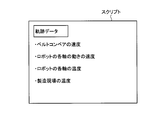
- the trajectory data creation unit 131 creates a script that is one data file as shown in FIG.
- the script in FIG. 10 describes the contents of the locus data, and also the speed of the belt conveyor 190, the speed of movement of each axis of the robots 161, 162, the temperature of each axis of the robots 161, 162, the manufacturing site Information such as the temperature of is added. That is, the script contains the information necessary for the client 140 to simulate the operating condition of the plant facility 1.
- the server 130 transmits the trajectory data to the client 140
- information such as the trajectory data and the speed of the belt conveyor 190 may be transmitted as separate files.
- the locus data is described in a script file
- the speed of the belt conveyor 190 and further, the speed of movement of each axis of the robots 161 and 162 are described in the speed file.
- the temperature of each axis of 162 and the temperature at the manufacturing site are described in the temperature file.
- the locus data creation unit 131 of the server 130 creates a script file in which only locus data is described.
- the server 130 further uses the data acquired from the database 120 to create a velocity file and a temperature file.
- a script file containing trajectory data and a file containing information obtained from the database 120 are divided, but the configuration of files other than the script file is not limited to the configuration shown in FIG.
- the server 130 transmits the data to the client 140 (FIG. 4, FIG. 9, step S205).
- the three-dimensional shape file 133 for each time of the defined period, the bit map file 134, and the script shown in FIG. Send to client 140.
- the second method of transmitting data from the server 130 to the client 140 the three-dimensional shape file 133 for each time of the defined period, the bit map file 134, the script file shown in FIG. 11, the speed file and the temperature
- the file is sent from the server 130 to the client 140.
- the monitoring system 100 may adopt any of the above-described methods as a method of transmitting data from the server 130 to the client 140.
- the locus data interpretation unit 141 of the client 140 interprets the locus data (FIG. 4, step S206). Specifically, based on the instruction of “real time reproduction”, “normal reproduction” or “reverse reproduction” accepted by the client 140, the locus data interpretation unit 141 extracts the locus data included in the script or script file. Interpret and combine the image of the bitmap file 134 with the three-dimensional coordinates indicated by the point cloud of the three-dimensional shape file 133 for each time, and display the image data of one screen each for continuous display in time series create.
- the locus data interpretation unit 141 also refers to the speed of the belt conveyor 190 received from the server 130 when creating image data.
- the trajectory data interpretation unit 141 may further refer to the angle of each axis of the robots 161 and 162 and the movement speed of each axis when creating image data. Further, when creating the image data, the locus data interpretation unit 141 may express the temperature of each axis of the robots 161 and 162 and the temperature of the manufacturing site using numerical values or colors. As described above, the trajectory data interpretation unit 141 can create image data that simulates not only the robots 161 and 162 but also the workpiece 170 and the belt conveyor 190.
- trajectory data interpretation unit 141 continuously displays image data for each time period that further divides the time period determined according to the instruction of “real time reproduction”, “normal reproduction” or “reverse reproduction”, the robot 161 , 162, and creates image data for each screen so as to be a moving image composed of a three-dimensional graphic simulating the workpiece 170 and the belt conveyor 190.
- the simulator unit 142 of the client 140 causes the display unit 143 to display an image using the image data created by the trajectory data interpretation unit 141 (FIG. 4, step S207). Specifically, the image data created by the locus data interpretation unit 141 is displayed at each time when the period defined in accordance with the instruction of “real time reproduction”, “normal reproduction” or “reverse reproduction” is further subdivided As described above, when the simulator unit 142 controls the display unit 143, it is possible to cause the display unit 143 to display an image according to the instruction of “real time reproduction”, “normal reproduction”, or “reverse reproduction”.
- Step S201 is executed when the apparatus receives it.
- FIG. 14 shows the state of the screen of the display unit 143 during execution of “normal reproduction” in step S207 after the input device of the client 140 receives “normal reproduction” in step S201, and the locus data interpretation unit 141 Since the created image data is displayed as thumbnails 301,..., 305,..., 310 and the bar 300 is at the position of the thumbnail 305, the enlarged screen of the thumbnail 305 is displayed as the large screen 1305 .
- the display unit 143 of the client 140 can simulate and display not only the actual motions of the robots 161 and 162 but also the actual motions of the workpiece 170 and the belt conveyor 190.
- the simulator unit 142 detects the thumbnail of the movement destination time of the bar 300 from the enlarged screen. The moving image can be reproduced on the display unit 143.
- the client 140 determines whether to end the display (FIG. 4, step S208).
- the client 140 determines that the display of the video on the display unit 143 is ended. (Step S208: Yes), the display is ended as soon as the reverse reproduction for the currently acquired data is completed.
- the client 140 determines that the display of the video on the display unit 143 is continued (step S208 No), the process returns to step S202, and steps S202 to S207 are repeated.
- the viewpoint position for the three-dimensional shape of the factory facility 1 in the video displayed on the display unit 143 is given via the input device, that is, the direction in which the user views the three-dimensional shape is given.
- the simulator unit 142 simulates a motion of a three-dimensional shape viewed from a given viewpoint position.
- the simulator unit 142 can cause the display unit 143 to display an image simulating an operation of a three-dimensional shape viewed from an arbitrary viewpoint position desired by the user.
- the operations of the robots 161 and 162 and the work 170 can be simulated. Therefore, according to the monitoring system 100 according to the first embodiment, not only the actual operations of the robots 161 and 162 at the actual manufacturing site, but also the actual operations of the workpiece 170 and the belt conveyor 190 can be reproduced and displayed. As a result, it is possible to simulate a trouble such as a collision between the workpiece 170 on the belt conveyor 190 and the robots 161 and 162, and to display an image of a moving image composed of a three-dimensional graphic on the client 140.
- the display unit 143 normally executes “real-time reproduction” based on a user's instruction, the user is not always monitoring the display unit 143.
- the user can instruct “normal playback” with the playback time or can issue “reverse playback” with the reverse playback time.
- the client 140 having received the instruction collects necessary information from the database 120 via the server 130, thereby moving the movie simulating the situation of the manufacturing site from the desired time backward in the forward direction on the time axis. It is also possible to cause the display unit 143 to reproduce and check the cause of the trouble.
- the client 140 changes the viewpoint position of the three-dimensional graphic simulating the manufacturing site by reproducing the three-dimensional graphic based on the information acquired from the manufacturing site. Is easily possible. Therefore, unlike monitoring a manufacturing site with a video camera as in the prior art, in the monitoring system 100 according to the first embodiment, no blind spot in the monitored area occurs. As a result, maintenance of the factory facility 1 is facilitated, and information required for monitoring can be significantly reduced as compared with the conventional case of monitoring using a video camera, thus contributing to a reduction in the amount of communication. .
- FIG. 15 is a flow chart for explaining the processing of the client 140 and the server 130 when a trouble occurs in the first embodiment.
- FIG. 16 is a diagram for explaining the flow of processing of the client 140 and the server 130 when a problem occurs in the first embodiment.
- FIG. 17 is a diagram for explaining the flow of processing of the client 140 at the time of troubleshooting in the first embodiment.
- FIG. 18 is a diagram for explaining the flow of processing of the server 130 at the time of troubleshooting in the first embodiment.
- an alarm occurs (FIG. 15, step S301).
- the alarm is generated by a device such as the robot control device 151 or 152 or the belt conveyor 190 that has detected a problem.
- the alarm monitoring unit 132 of the server 130 that has detected alarm information generated by the robot controller 151 or 152 or the belt conveyor 190 via the network 200 notifies the client 140 of the occurrence of an alarm (FIG. 15, FIG. 16, step S302). ).
- FIG. 16 illustrates a state in which the robot control device 151 notifies the server 130 of alarm information via the network 200, and the server 130 notifies the client 140 of the occurrence of an alarm.
- the client 140 notified of the occurrence of the alarm from the server 130 notifies the user of the occurrence of the alarm (FIG. 15, step S303).
- the method of notifying the user of the occurrence of the alarm by the client 140 may be notified via the display unit 143 or may be notified using voice, and the method is not limited. At this time, the client 140 may notify the user of an alarm occurrence time.
- the user notified of the occurrence of the alarm instructs either “normal play” or “reverse play” by clicking the “normal play” button 402 or “reverse play” button 403 in FIG.
- the input device 140 receives an instruction from the user (FIG. 4, step S201).
- the user may input the reproduction time or the reverse reproduction time with reference to the occurrence time of the alarm and make the input device accept it at step S201.
- the client 140 having received either "normal playback” or "reverse playback” executes "normal playback” or "reverse playback” according to FIG. 4 (FIG. 15, step S304), and displays the video on the display unit 143. Do.
- the user who has watched the playback video can examine the cause of the trouble in detail. When it is difficult to identify the cause in “normal playback”, “reverse playback” may make it easier to identify the cause.
- the trouble is a collision between the work 170 and the robot 161, 162
- the user can judge that the collision is generated due to the lack of control information of the robot 161, 162 described in the control program of the robot control device 151, 152. In some cases. In this case, the user needs to correct the operation setting information of the robots 161 and 162. Specifically, the user instructs correction of position data or angle data of each axis described in the control program. Then, the client 140 receives an instruction to correct the control program from the user (FIG. 15, step S305).
- the client 140 acquires the control program of the robot control devices 151 and 152 in advance via the network 200 and the server 130, and the user corrects the control program held by the storage device of the client 140 and corrects it.
- the client 140 may receive a control program correction instruction.
- the client 140 may also receive a correction instruction of the control program by receiving the correction content of the control program by the user.
- the client 140 having received the control program correction instruction transmits the correction instruction to the server 130 (FIG. 15, FIG. 17, step S306). Furthermore, the server 130 that has received the control program correction instruction transmits the correction instruction to the robot control device 151 (FIG. 15, FIG. 18, step S307).
- the robot control device 151 that has received the control program correction instruction corrects the control program. If the correction instruction of the received control program is the control program after correction, the robot control device 151 may overwrite the control program with the corrected control program, and the correction instruction of the received control program corrects the control program If the content is the content, the control program may be corrected according to the content of the correction.
- the monitoring system 100 in addition to the actual operations of the robots 161 and 162 at the manufacturing site, it is possible to monitor an image that reproduces and displays the actual operations of the workpiece 170 and the belt conveyor 190 as well.
- the user can instruct modification of the control program of the robots 161 and 162.
- the control program of the robots 161 and 162 can be corrected from a remote place without the user having to go to the manufacturing site, and it becomes possible to solve the trouble quickly or unmanage the manufacturing site.
- the file format of the three-dimensional shape file 133 held by the server 130 may conform to the data format of data of three-dimensional coordinates of each axis of the robots 161 and 162 included in the control program. That is, the data format of data of three-dimensional coordinates of each axis of the robots 161 and 162 in the control program may be the same as the data format of the file format of the three-dimensional shape file 133.
- three-dimensional CAD is performed for holding information on three-dimensional coordinates indicating the operating status of the factory facility 1, and for creating and correcting data on three-dimensional coordinates of the manufacturing apparatus described in the control program.
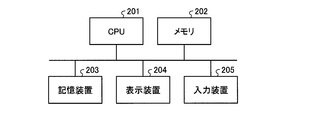
- FIG. 19 is a diagram showing a hardware configuration when a part of the functions of the logging unit 110, the client 140 or the server 130 according to the first embodiment is realized by a computer.
- a part of the functions of the logging unit 110, the client 140 or the server 130 is realized by a computer
- a part of the functions of the logging unit 110, the client 140 or the server 130 are CPU (Central Processing Unit) 201 as shown in FIG.
- the memory 202, the storage device 203, the display device 204, and the input device 205 Some of the functions of the logging unit 110, the client 140, or the server 130 are realized by software, firmware, or a combination of software and firmware.
- the software or firmware is described as a program and stored in the storage device 203.
- the CPU 201 realizes a part of the functions of the logging unit 110, the client 140 or the server 130 by reading out software or firmware stored in the storage device 203 into the memory 202 and executing the software or firmware. That is, the step in which the logging unit 110, the client 140 or the server 130 implements a part of the functions of the logging unit 110, the client 140 or the server 130 when the part of their functions is executed by the computer results in A storage device 203 is provided for storing the program to be executed. In addition, it can be said that these programs cause a computer to execute processing realized by part of the functions of the logging unit 110, the client 140 or the server 130.
- the memory 202 corresponds to a volatile storage area such as a random access memory (RAM).
- the storage device 203 corresponds to a non-volatile or volatile semiconductor memory such as a read only memory (ROM), a flash memory, or a magnetic disk.
- ROM read only memory
- the display device 204 are a monitor and a display.
- the display unit 143 of the client 140 is realized by the display device 204.
- Specific examples of the input device 205 are a keyboard, a mouse, and a touch panel.
- the configuration shown in the above embodiment shows an example of the contents of the present invention, and can be combined with another known technique, and one of the configurations is possible within the scope of the present invention. Parts can be omitted or changed.
Landscapes
- Engineering & Computer Science (AREA)
- Physics & Mathematics (AREA)
- General Physics & Mathematics (AREA)
- Automation & Control Theory (AREA)
- Manufacturing & Machinery (AREA)
- General Engineering & Computer Science (AREA)
- Quality & Reliability (AREA)
- Testing And Monitoring For Control Systems (AREA)
- General Factory Administration (AREA)
- Manipulator (AREA)
Priority Applications (4)
| Application Number | Priority Date | Filing Date | Title |
|---|---|---|---|
| CN201780095495.2A CN111183401B (zh) | 2017-10-05 | 2017-10-05 | 监视系统及监视方法 |
| PCT/JP2017/036381 WO2019069436A1 (ja) | 2017-10-05 | 2017-10-05 | 監視装置、監視システムおよび監視方法 |
| JP2018530932A JP6430079B1 (ja) | 2017-10-05 | 2017-10-05 | 監視システムおよび監視方法 |
| US16/643,590 US11163298B2 (en) | 2017-10-05 | 2017-10-05 | Monitoring system and monitoring method |
Applications Claiming Priority (1)
| Application Number | Priority Date | Filing Date | Title |
|---|---|---|---|
| PCT/JP2017/036381 WO2019069436A1 (ja) | 2017-10-05 | 2017-10-05 | 監視装置、監視システムおよび監視方法 |
Publications (1)
| Publication Number | Publication Date |
|---|---|
| WO2019069436A1 true WO2019069436A1 (ja) | 2019-04-11 |
Family
ID=64480546
Family Applications (1)
| Application Number | Title | Priority Date | Filing Date |
|---|---|---|---|
| PCT/JP2017/036381 WO2019069436A1 (ja) | 2017-10-05 | 2017-10-05 | 監視装置、監視システムおよび監視方法 |
Country Status (4)
| Country | Link |
|---|---|
| US (1) | US11163298B2 (zh) |
| JP (1) | JP6430079B1 (zh) |
| CN (1) | CN111183401B (zh) |
| WO (1) | WO2019069436A1 (zh) |
Cited By (2)
| Publication number | Priority date | Publication date | Assignee | Title |
|---|---|---|---|---|
| JP7075541B1 (ja) * | 2020-12-22 | 2022-05-25 | 三菱電機株式会社 | 不具合解析支援プログラム |
| US11949847B2 (en) | 2019-09-30 | 2024-04-02 | Dwango Co., Ltd. | Recording device, reproduction device, system, recording method, reproduction method, recording program, and reproduction program |
Families Citing this family (6)
| Publication number | Priority date | Publication date | Assignee | Title |
|---|---|---|---|---|
| JP6450726B2 (ja) * | 2016-10-26 | 2019-01-09 | ファナック株式会社 | ロボットの動作をシミュレーションするシミュレーション装置、およびシミュレーション方法 |
| DE102018116611B4 (de) * | 2018-07-10 | 2022-02-10 | Dematic Gmbh | Verfahren und System zur Steuerung des Materialflusses von Objekten in einem realen Lager |
| CN111360816A (zh) * | 2018-12-26 | 2020-07-03 | 沈阳新松机器人自动化股份有限公司 | 一种机器人的控制方法、系统及机器人 |
| WO2020150870A1 (en) * | 2019-01-21 | 2020-07-30 | Abb Schweiz Ag | Method and apparatus for monitoring robot system |
| JP7505919B2 (ja) | 2020-05-29 | 2024-06-25 | 日鉄テックスエンジ株式会社 | 工場設備監視システム、工場設備監視方法及びプログラム |
| CN113194283A (zh) * | 2021-04-14 | 2021-07-30 | 深圳赛动生物自动化有限公司 | 一种视频监控的智能控制方法、装置及设备 |
Citations (5)
| Publication number | Priority date | Publication date | Assignee | Title |
|---|---|---|---|---|
| JPH1124735A (ja) * | 1997-06-27 | 1999-01-29 | Mitsubishi Electric Corp | プラント運転支援システム |
| JP2000250775A (ja) * | 1999-03-01 | 2000-09-14 | Omron Corp | トラブル解析支援装置及びシミュレーション装置 |
| JP2000259239A (ja) * | 1999-03-12 | 2000-09-22 | Omron Corp | ロギング装置、ロギングシステム及びロギングレポート |
| JP2013222258A (ja) * | 2012-04-13 | 2013-10-28 | Mitsubishi Electric Corp | 監視制御装置 |
| WO2016189704A1 (ja) * | 2015-05-27 | 2016-12-01 | 三菱電機株式会社 | 制御装置、及びデータ再生装置 |
Family Cites Families (15)
| Publication number | Priority date | Publication date | Assignee | Title |
|---|---|---|---|---|
| JP3305451B2 (ja) | 1993-08-27 | 2002-07-22 | 株式会社安川電機 | ロボット制御装置 |
| JP2000132214A (ja) | 1998-10-27 | 2000-05-12 | Mitsubishi Electric Corp | 加工機遠隔監視装置 |
| JP3667139B2 (ja) * | 1999-03-03 | 2005-07-06 | キヤノン株式会社 | 画像形成装置 |
| US6788218B2 (en) * | 2001-07-19 | 2004-09-07 | Lancer Partnership, Ltd. | Pseudo real-time diagnostic and process monitoring system |
| JP3529373B2 (ja) * | 2001-11-09 | 2004-05-24 | ファナック株式会社 | 作業機械のシミュレーション装置 |
| JP4505295B2 (ja) * | 2004-09-16 | 2010-07-21 | ヤマザキマザック株式会社 | Nc加工シミュレーション方法及びnc加工シミュレーション装置 |
| JP2008217608A (ja) | 2007-03-06 | 2008-09-18 | Farukomu:Kk | 産業機械の遠隔監視システム及び方法 |
| US7831411B2 (en) * | 2007-05-25 | 2010-11-09 | Rockwell Automation Technologies, Inc. | Diagnostic tool for retroactive assessment of industrial process performance |
| US20080307304A1 (en) * | 2007-06-07 | 2008-12-11 | Ernst Feiler | Method and system for producing a sequence of views |
| US10648888B2 (en) * | 2008-02-27 | 2020-05-12 | Mitsubishi Hitachi Power Systems, Ltd. | Plant state monitoring method, plant state monitoring computer program, and plant state monitoring apparatus |
| US8615683B2 (en) * | 2011-06-24 | 2013-12-24 | Rockwell Automation Technologies, Inc. | Capturing data during operation of an industrial controller for the debugging of control programs |
| US9939793B2 (en) * | 2012-08-03 | 2018-04-10 | Toshiba Mitsubishi-Electric Industrial Systems Corporation | Plant control monitoring system |
| US9278449B1 (en) * | 2014-05-21 | 2016-03-08 | Bot & Dolly, Llc | Closed-loop control system for robotic operation |
| JP6392817B2 (ja) * | 2016-08-04 | 2018-09-19 | ファナック株式会社 | シミュレーション装置 |
| JP6789871B2 (ja) * | 2017-03-31 | 2020-11-25 | 株式会社荏原製作所 | 半導体製造装置の動作に関する表示を制御する方法を実行するプログラム、当該方法及び半導体製造装置の動作に関する表示を行うシステム |
-
2017
- 2017-10-05 JP JP2018530932A patent/JP6430079B1/ja active Active
- 2017-10-05 CN CN201780095495.2A patent/CN111183401B/zh active Active
- 2017-10-05 WO PCT/JP2017/036381 patent/WO2019069436A1/ja active Application Filing
- 2017-10-05 US US16/643,590 patent/US11163298B2/en active Active
Patent Citations (5)
| Publication number | Priority date | Publication date | Assignee | Title |
|---|---|---|---|---|
| JPH1124735A (ja) * | 1997-06-27 | 1999-01-29 | Mitsubishi Electric Corp | プラント運転支援システム |
| JP2000250775A (ja) * | 1999-03-01 | 2000-09-14 | Omron Corp | トラブル解析支援装置及びシミュレーション装置 |
| JP2000259239A (ja) * | 1999-03-12 | 2000-09-22 | Omron Corp | ロギング装置、ロギングシステム及びロギングレポート |
| JP2013222258A (ja) * | 2012-04-13 | 2013-10-28 | Mitsubishi Electric Corp | 監視制御装置 |
| WO2016189704A1 (ja) * | 2015-05-27 | 2016-12-01 | 三菱電機株式会社 | 制御装置、及びデータ再生装置 |
Cited By (5)
| Publication number | Priority date | Publication date | Assignee | Title |
|---|---|---|---|---|
| US11949847B2 (en) | 2019-09-30 | 2024-04-02 | Dwango Co., Ltd. | Recording device, reproduction device, system, recording method, reproduction method, recording program, and reproduction program |
| JP7075541B1 (ja) * | 2020-12-22 | 2022-05-25 | 三菱電機株式会社 | 不具合解析支援プログラム |
| WO2022137358A1 (ja) * | 2020-12-22 | 2022-06-30 | 三菱電機株式会社 | 不具合解析支援プログラム、不具合解析支援装置、不具合解析支援方法および三次元データ表示プログラム |
| JP2022099341A (ja) * | 2020-12-22 | 2022-07-04 | 三菱電機株式会社 | 不具合解析支援プログラム、不具合解析支援装置、不具合解析支援方法および三次元データ表示プログラム |
| JP7504149B2 (ja) | 2020-12-22 | 2024-06-21 | 三菱電機株式会社 | 不具合解析支援装置、不具合解析支援方法および不具合解析支援プログラム |
Also Published As
| Publication number | Publication date |
|---|---|
| JP6430079B1 (ja) | 2018-11-28 |
| JPWO2019069436A1 (ja) | 2019-11-14 |
| US20200241513A1 (en) | 2020-07-30 |
| US11163298B2 (en) | 2021-11-02 |
| CN111183401B (zh) | 2021-07-06 |
| CN111183401A (zh) | 2020-05-19 |
Similar Documents
| Publication | Publication Date | Title |
|---|---|---|
| JP6430079B1 (ja) | 監視システムおよび監視方法 | |
| US10751877B2 (en) | Industrial robot training using mixed reality | |
| JP6551184B2 (ja) | シミュレーション装置、シミュレーション方法、およびシミュレーションプログラム | |
| TWI540534B (zh) | 虛擬導覽控制系統與方法 | |
| US20150379171A1 (en) | Robot simulator and file generation method for robot simulator | |
| US20100091036A1 (en) | Method and System for Integrating Virtual Entities Within Live Video | |
| JP7471428B2 (ja) | 製造又は産業環境における協調ロボットとの相互作用のために仮想/拡張現実を使用するためのシステム、方法及びコンピュータ読み取り可能媒体 | |
| KR20120072126A (ko) | 간접체험을 위한 비주얼 서로게이트와 그 공급 장치 및 방법 | |
| US10964104B2 (en) | Remote monitoring and assistance techniques with volumetric three-dimensional imaging | |
| KR102203234B1 (ko) | Mr기반의 도시철도 기관사 운전연습시스템 및 그 시스템의 구동방법 | |
| Liang et al. | Real-time state synchronization between physical construction robots and process-level digital twins | |
| Bednarz et al. | Distributed collaborative immersive virtual reality framework for the mining industry | |
| WO2018222188A1 (en) | Remote collaboration based on multi-modal communications and 3d model visualization in a shared virtual workspace | |
| CN115213890B (zh) | 抓取的控制方法、装置、服务器、电子设备及存储介质 | |
| CN111598273A (zh) | 一种基于vr技术的环控生保系统维修性检测方法及装置 | |
| JP4053627B2 (ja) | 通信型コンピュータグラフィックスアニメーション方法 | |
| Taylor et al. | Interactive virtual reality in simulations: Exploring lag time | |
| CN112233208B (zh) | 机器人状态处理方法、装置、计算设备和存储介质 | |
| Wang | Improving human-machine interfaces for construction equipment operations with mixed and augmented reality | |
| WO2020067204A1 (ja) | 学習用データ作成方法、機械学習モデルの生成方法、学習用データ作成装置及びプログラム | |
| JP2842283B2 (ja) | 映像提示方法および装置 | |
| JP3763646B2 (ja) | プラント模擬装置 | |
| Fucci et al. | Measuring audio-visual latencies in virtual reality systems | |
| Horváth et al. | A use case of the simulation-based approach to mobile robot algorithm development | |
| KR102664178B1 (ko) | 디지털트윈 기반 영상 감시 방법 |
Legal Events
| Date | Code | Title | Description |
|---|---|---|---|
| ENP | Entry into the national phase |
Ref document number: 2018530932 Country of ref document: JP Kind code of ref document: A |
|
| 121 | Ep: the epo has been informed by wipo that ep was designated in this application |
Ref document number: 17928033 Country of ref document: EP Kind code of ref document: A1 |
|
| NENP | Non-entry into the national phase |
Ref country code: DE |
|
| 122 | Ep: pct application non-entry in european phase |
Ref document number: 17928033 Country of ref document: EP Kind code of ref document: A1 |