WO2019069436A1 - Monitoring device, monitoring system, and monitoring method - Google Patents
Monitoring device, monitoring system, and monitoring method Download PDFInfo
- Publication number
- WO2019069436A1 WO2019069436A1 PCT/JP2017/036381 JP2017036381W WO2019069436A1 WO 2019069436 A1 WO2019069436 A1 WO 2019069436A1 JP 2017036381 W JP2017036381 W JP 2017036381W WO 2019069436 A1 WO2019069436 A1 WO 2019069436A1
- Authority
- WO
- WIPO (PCT)
- Prior art keywords
- data
- information
- dimensional coordinates
- monitoring
- client
- Prior art date
Links
Images


Classifications
-
- G—PHYSICS
- G05—CONTROLLING; REGULATING
- G05B—CONTROL OR REGULATING SYSTEMS IN GENERAL; FUNCTIONAL ELEMENTS OF SUCH SYSTEMS; MONITORING OR TESTING ARRANGEMENTS FOR SUCH SYSTEMS OR ELEMENTS
- G05B19/00—Programme-control systems
- G05B19/02—Programme-control systems electric
- G05B19/04—Programme control other than numerical control, i.e. in sequence controllers or logic controllers
- G05B19/042—Programme control other than numerical control, i.e. in sequence controllers or logic controllers using digital processors
-
- G—PHYSICS
- G05—CONTROLLING; REGULATING
- G05B—CONTROL OR REGULATING SYSTEMS IN GENERAL; FUNCTIONAL ELEMENTS OF SUCH SYSTEMS; MONITORING OR TESTING ARRANGEMENTS FOR SUCH SYSTEMS OR ELEMENTS
- G05B19/00—Programme-control systems
- G05B19/02—Programme-control systems electric
- G05B19/04—Programme control other than numerical control, i.e. in sequence controllers or logic controllers
- G05B19/05—Programmable logic controllers, e.g. simulating logic interconnections of signals according to ladder diagrams or function charts
- G05B19/058—Safety, monitoring
-
- G—PHYSICS
- G05—CONTROLLING; REGULATING
- G05B—CONTROL OR REGULATING SYSTEMS IN GENERAL; FUNCTIONAL ELEMENTS OF SUCH SYSTEMS; MONITORING OR TESTING ARRANGEMENTS FOR SUCH SYSTEMS OR ELEMENTS
- G05B19/00—Programme-control systems
- G05B19/02—Programme-control systems electric
- G05B19/418—Total factory control, i.e. centrally controlling a plurality of machines, e.g. direct or distributed numerical control [DNC], flexible manufacturing systems [FMS], integrated manufacturing systems [IMS], computer integrated manufacturing [CIM]
- G05B19/41885—Total factory control, i.e. centrally controlling a plurality of machines, e.g. direct or distributed numerical control [DNC], flexible manufacturing systems [FMS], integrated manufacturing systems [IMS], computer integrated manufacturing [CIM] characterised by modeling, simulation of the manufacturing system
-
- G—PHYSICS
- G05—CONTROLLING; REGULATING
- G05B—CONTROL OR REGULATING SYSTEMS IN GENERAL; FUNCTIONAL ELEMENTS OF SUCH SYSTEMS; MONITORING OR TESTING ARRANGEMENTS FOR SUCH SYSTEMS OR ELEMENTS
- G05B23/00—Testing or monitoring of control systems or parts thereof
- G05B23/02—Electric testing or monitoring
-
- B—PERFORMING OPERATIONS; TRANSPORTING
- B25—HAND TOOLS; PORTABLE POWER-DRIVEN TOOLS; MANIPULATORS
- B25J—MANIPULATORS; CHAMBERS PROVIDED WITH MANIPULATION DEVICES
- B25J9/00—Programme-controlled manipulators
- B25J9/16—Programme controls
- B25J9/1656—Programme controls characterised by programming, planning systems for manipulators
- B25J9/1671—Programme controls characterised by programming, planning systems for manipulators characterised by simulation, either to verify existing program or to create and verify new program, CAD/CAM oriented, graphic oriented programming systems
-
- G—PHYSICS
- G05—CONTROLLING; REGULATING
- G05B—CONTROL OR REGULATING SYSTEMS IN GENERAL; FUNCTIONAL ELEMENTS OF SUCH SYSTEMS; MONITORING OR TESTING ARRANGEMENTS FOR SUCH SYSTEMS OR ELEMENTS
- G05B19/00—Programme-control systems
- G05B19/02—Programme-control systems electric
- G05B19/418—Total factory control, i.e. centrally controlling a plurality of machines, e.g. direct or distributed numerical control [DNC], flexible manufacturing systems [FMS], integrated manufacturing systems [IMS], computer integrated manufacturing [CIM]
- G05B19/41815—Total factory control, i.e. centrally controlling a plurality of machines, e.g. direct or distributed numerical control [DNC], flexible manufacturing systems [FMS], integrated manufacturing systems [IMS], computer integrated manufacturing [CIM] characterised by the cooperation between machine tools, manipulators and conveyor or other workpiece supply system, workcell
- G05B19/41825—Total factory control, i.e. centrally controlling a plurality of machines, e.g. direct or distributed numerical control [DNC], flexible manufacturing systems [FMS], integrated manufacturing systems [IMS], computer integrated manufacturing [CIM] characterised by the cooperation between machine tools, manipulators and conveyor or other workpiece supply system, workcell machine tools and manipulators only, machining centre
-
- G—PHYSICS
- G05—CONTROLLING; REGULATING
- G05B—CONTROL OR REGULATING SYSTEMS IN GENERAL; FUNCTIONAL ELEMENTS OF SUCH SYSTEMS; MONITORING OR TESTING ARRANGEMENTS FOR SUCH SYSTEMS OR ELEMENTS
- G05B2219/00—Program-control systems
- G05B2219/30—Nc systems
- G05B2219/40—Robotics, robotics mapping to robotics vision
- G05B2219/40311—Real time simulation
-
- Y—GENERAL TAGGING OF NEW TECHNOLOGICAL DEVELOPMENTS; GENERAL TAGGING OF CROSS-SECTIONAL TECHNOLOGIES SPANNING OVER SEVERAL SECTIONS OF THE IPC; TECHNICAL SUBJECTS COVERED BY FORMER USPC CROSS-REFERENCE ART COLLECTIONS [XRACs] AND DIGESTS
- Y02—TECHNOLOGIES OR APPLICATIONS FOR MITIGATION OR ADAPTATION AGAINST CLIMATE CHANGE
- Y02P—CLIMATE CHANGE MITIGATION TECHNOLOGIES IN THE PRODUCTION OR PROCESSING OF GOODS
- Y02P90/00—Enabling technologies with a potential contribution to greenhouse gas [GHG] emissions mitigation
- Y02P90/02—Total factory control, e.g. smart factories, flexible manufacturing systems [FMS] or integrated manufacturing systems [IMS]
Definitions
- the present invention relates to a monitoring device, a monitoring system and a monitoring method for maintenance of factory equipment.
- the monitoring apparatus consisting of the conventional surveillance camera is recording from one direction of the surveillance camera, it is impossible to reproduce the detailed operation of the manufacturing site which becomes the blind spot of the surveillance camera, and the manufacturing apparatus such as a robot There was a problem that it took time to identify the cause when trouble occurred or it was difficult to identify the cause. In addition, even if a trouble is notified from the monitoring device, in order to solve the trouble, the user needs to go to the manufacturing site, reproduce and confirm the trouble, and identify the cause.
- Patent Document 1 two robot control devices and one monitor device are connected, and the operation states of the two robots are drawn in real time on the display screen of one monitor device, whereby the robot operation is performed.
- the monitoring device periodically collects the current value of the joint angle of the robot from the joint angle server on the robot control device via the communication network, and updates the drawing data of the robot.
- Patent Document 1 aims to monitor the operation state of the robot, and only the current value of the joint angle of the robot is collected to execute the simulation. Therefore, although it is possible to reconfirm the robot simulation using the current value of the joint angle, it is possible to realistically simulate the trouble under the facility operating condition such as the collision between the transported object on the belt conveyor and the robot. No, I could not use the simulation to take measures against the problem.
- the present invention has been made in view of the above, and it is an object of the present invention to obtain a monitoring device that makes it possible to simulate the operating condition of factory equipment including a manufacturing device.
- the present invention acquires information of three-dimensional coordinates at each time indicating the operation status of factory equipment.
- the present invention is a locus that describes a command on how to combine information of an image showing the operation status of factory equipment with three-dimensional coordinates based on the three-dimensional coordinates for each time and the received reproduction instruction.
- a trajectory data generation unit for generating data is provided.
- the monitoring apparatus concerning this invention has an effect that it becomes possible to simulate the working condition of the factory installation containing a manufacturing apparatus.
- Block diagram showing the configuration of factory equipment according to the first embodiment of the present invention Block diagram showing the detailed configuration of the monitoring system according to the first embodiment Flowchart for explaining the operation of the logging unit according to the first embodiment Flow chart for explaining processing of client and server according to the first embodiment A diagram for explaining “real time reproduction” according to the first embodiment A diagram for explaining “normal reproduction” according to the first embodiment A diagram for explaining “reverse reproduction” according to the first embodiment Diagram for explaining the flow of client and server processing according to the first embodiment Another diagram for explaining the flow of client and server processing according to the first embodiment Diagram showing the configuration of a script according to the first embodiment A diagram showing the configuration of a script related file according to the first embodiment Diagram for explaining execution of “normal playback” according to the first embodiment Diagram for explaining execution of “reverse reproduction” according to the first embodiment FIG.
- FIG. 6 is a diagram showing a screen of a display unit during execution of “normal playback” according to the first embodiment.
- Flow chart for explaining processing of client and server when trouble occurs in the first embodiment Diagram for explaining the flow of client and server processing when a problem occurs in Embodiment 1
- the factory facility 1 further includes a sensor 180 that detects the position of the workpiece 170, a sensor 181 that detects the temperature of the robot 161, and a sensor 182 that detects the temperature of the robot 162.
- the temperature of each of the robots 161 and 162 is the temperature of each axis corresponding to each joint of the robot arms constituting the robots 161 and 162.
- the robot control devices 151 and 152, the sensors 180, 181 and 182, and the belt conveyor 190 are connected to the network 200.
- the network 200 may be wired or wireless.
- the factory installation 1 is provided with a monitoring system 100 that monitors the states of the robots 161 and 162 and the work 170.
- the monitoring system 100 includes a logging unit 110 having a logging function, a database 120 held in a storage device, a server 130 that is a monitoring device, and a client device 140 that is a client device that displays moving images that simulate the operation of the factory facility 1. And.
- the client 140 simulates and displays the operation of the three-dimensional shape of the factory facility 1.
- the logging unit 110, the database 120, the server 130 and the client 140 are connected to the network 200.
- the logging unit 110, the server 130 and the client 140 are realized by a computer.
- the logging unit 110 and the server 130 may be realized by separate computers, but one computer may realize the functions of both.
- the client 140 simulates and displays the operation of the three-dimensional shape of the manufacturing site in the plant facility 1 based on the data acquired from the server 130.
- the logging unit 110 acquires information of three-dimensional coordinates for each time indicating the operation status of the factory facility 1 including the manufacturing apparatus.
- the factory equipment 1 includes the belt conveyor 190 in addition to the robots 161 and 162, and the operation status of the factory equipment 1 also includes the situation of the workpiece 170. Therefore, specifically, the logging unit 110 collects data such as the position and angle of each axis of the robots 161 and 162, the speed of the belt conveyor 190, the position of the workpiece 170, and the time information at a constant cycle.
- the logging unit 110 transfers the collected data to the database 120 via the network 200 and stores the data in the database 120.
- the server 130 accesses the database 120 to acquire necessary data.
- the client 140 requests the server 130 for data necessary for the reproduction operation of the manufacturing apparatus and the manufacturing line.
- FIG. 2 is a block diagram showing the detailed configuration of the monitoring system 100 according to the first embodiment.
- FIG. 3 is a flowchart for explaining the operation of the logging unit 110 according to the first embodiment. Note that FIG. 2 omits some of the components of FIG. 1 for the sake of simplicity.
- the operation period of the plant facility 1 is N cycles when the cycle in which the logging unit 110 collects information is taken as a unit.
- the logging unit 110 collects data from the robot control devices 151 and 152, the belt conveyor 190, and the sensors 180, 181 and 182 (step S101).
- the logging unit 110 is a position and an angle of each axis of the robot 161, 162 from the robot control device 151, 152, a speed of the belt conveyor 190 from the belt conveyor 190, a position of the work 170 from the sensor 180,
- Data such as the temperatures of the robots 161 and 162 from the sensors 181 and 182 are collected via the network 200 together with time information.
- the data collected by the logging unit 110 via the network 200 may include the speed of movement of each axis of the robots 161 and 162, the temperature of the manufacturing line and the manufacturing site where the manufacturing apparatus is installed. .
- the logging unit 110 saves the collected data in the database 120 for each time (step S102).
- the logging unit 110 acquires the position and angle of each axis of the robots 161 and 162, the speed of the belt conveyor 190, the position of the workpiece 170 and the temperature of the robots 161 and 162 for each fixed cycle, and the database together with time information It can be stored at 120. If the absolute value of the difference between the value of the data collected at a certain timing and the value collected one cycle before the relevant timing is larger than a predetermined value, the logging unit 110 uses the data collected at the relevant timing. Determines that noise is superimposed, the data is discarded and the data is not stored in the database 120.
- the server 130 generates a locus data generation unit 131 that generates locus data relating to a locus of the three-dimensional shape of the plant facility 1 in response to a request from the client 140, and an alarm monitoring unit 132 that acquires alarm information and notifies the client 140. And a three-dimensional shape file 133 based on the information acquired from the database 120, and a bitmap file 134 which is image data.
- the locus data creation unit 131 creates a script or script file including locus data. As described later, a script is a data file in which data other than trajectory data is also described, but only trajectory data is described in the script file.
- the three-dimensional shape file 133 is a file having information of three-dimensional coordinates indicating the operating status of the factory equipment 1 including the manufacturing apparatus. Specifically, the three-dimensional shape file 133 is data including the data of the position of each axis of the robots 161 and 162 in the three-dimensional space and the data of the position of the workpiece 170 on the belt conveyor 190 in the three-dimensional space. is there.
- the three-dimensional shape file 133 contains information of three-dimensional coordinates of a skeleton or a point group to be an outline for displaying the robots 161 and 162 and the workpiece 170 in three-dimensional space.
- the data of the three-dimensional coordinates of each axis of the robots 161 and 162 is acquired by the logging unit 110 from the control program of the robots 161 and 162 possessed by the robot control devices 151 and 152 and fixed in the database 120 It is stored with the time information in a cycle. Further, the data of the three-dimensional coordinates of the workpiece 170 on the belt conveyor 190 is acquired by the logging unit 110 from the sensor 180 or the belt conveyor 190 and stored in the database 120 along with the time at a constant cycle. The client 140 accesses the database 120, and based on the data stored in the database 120, creates the three-dimensional shape file 133 for each time and saves it in its own storage device.
- the file format of the three-dimensional shape file 133 conforms to the data format of AutoCAD (registered trademark), SOLIDWORKS (registered trademark) or iCAD (registered trademark)
- the three-dimensional shape file 133 is AutoCAD (registered trademark), SOLIDWORKS (registered trademark) It is readable by registered trademark) or iCAD (registered trademark).
- the file format of the three-dimensional shape file 133 is three-dimensional file format Parasolid, Initial Graphics Exchange Specification (IGES), STEP, Standard Triangulated Language (STEP), VPS, Virtual Reality Modeling Language (VRML), CATIA V5 ( It may be a file format such as Computer graphics Aided Three dimensional Interactive Application V5), Pro / E, NX, I-deas or JT. Also, the file format of the three-dimensional shape file 133 is not limited to the existing format as described above, and may be a unique or new file format.
- the bit map file 134 is a file having image information indicating the operating status of the factory facility 1 including the manufacturing apparatus. Specifically, the bit map file 134 is a robot 161, 162 and a work required to draw the robot 161, 162 and the work 170 in the three-dimensional space by adding to the skeleton or outline indicated by the three-dimensional shape file 133. It is a file which shows the information of 170 images. That is, the bitmap file 134 is information of an image to be pasted on the three-dimensional space along the point group indicated by the three-dimensional shape file 133.
- the file format of the bitmap file 134 conforms to the data format of AutoCAD (registered trademark), SOLIDWORKS (registered trademark) or iCAD (registered trademark)
- the bitmap file 134 is AutoCAD (registered trademark), SOLIDWORKS (registered trademark) Or iCAD (registered trademark). Therefore, the file format of the bitmap file 134 may be a file format such as DXF (Drawing Exchange Format), DWG, ME-10, IGES, MicroCADAM drawing, DMNDOS, MCD or BMI.
- DWG is a standard file format of AutoCAD (registered trademark).
- the file format of the bitmap file 134 is not limited to the existing format as described above, and may be a unique or new file format.
- the client 140 simulates the operation of the three-dimensional shape of the factory facility 1 based on the interpretation result of the locus data interpretation unit 141 that interprets the locus data included in the script or script file acquired from the server 130 and the locus data interpretation unit 141.
- a simulator unit 142 to be executed and a display unit 143 for displaying the result of the operation simulation of the three-dimensional shape by the simulator unit 142 are provided.
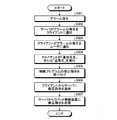
- FIG. 4 is a flowchart illustrating processing of the client 140 and the server 130 according to the first embodiment.
- FIG. 5 is a diagram for explaining “real time reproduction” according to the first embodiment.
- FIG. 6 is a diagram for explaining “normal reproduction” according to the first embodiment.
- FIG. 7 is a diagram for explaining “reverse reproduction” according to the first embodiment.
- FIG. 8 is a diagram for explaining the process flow of the client 140 and the server 130 according to the first embodiment.
- FIG. 9 is another diagram illustrating the process flow of the client 140 and the server 130 according to the first embodiment.
- FIG. 10 is a diagram showing the configuration of a script according to the first embodiment.
- FIG. 11 is a diagram showing the configuration of a script related file according to the first embodiment.
- FIG. 12 is a diagram for explaining the execution of the “normal reproduction” according to the first embodiment.
- FIG. 13 is a diagram for explaining the execution of “reverse reproduction” according to the first embodiment.
- FIG. 14 is a diagram of a screen of the display unit during execution of “normal playback” according to the first embodiment.
- the user instructs either playback or reverse playback, and the input device of the client 140 receives the user's instruction (FIG. 4, step S201). Specifically, the user instructs one of “real-time reproduction”, “normal reproduction”, and “reverse reproduction”, and the input device of the client 140 receives any instruction.
- both the reverse playback times are specified . If the current time and the reverse playback time are both 16:00, the user desires reverse playback as shown in FIG.
- the client 140 requests the server 130 to transmit necessary data (FIG. 4, FIG. 8, step S202).
- the client 140 notifies the server 130 of the “real-time playback”, “normal playback” or “reverse playback” instruction accepted in step S 201 and the period determined according to the instruction to the server 130,
- the server 130 is requested to transmit data for the period.
- the period determined in accordance with the instruction is a unit of time of data which is a group of data transfer in “real time reproduction”, “normal reproduction” or “reverse reproduction”.
- the server 130 may initially hold a period determined in accordance with “real time reproduction”, “normal reproduction”, or “reverse reproduction”.
- a specific example of the defined period is a period of 1 second in the case of "real time reproduction”, or 5 seconds in the case of "normal reproduction” or “reverse reproduction”. Then, even when the client 140 receives any of “real time reproduction”, “normal reproduction”, and “reverse reproduction”, the process from step S202 to step S207 described later is performed periodically based on the above-mentioned determined period. The request from the client 140 to the server 130 in step S202 will also be periodically executed.
- the server 130 having received the request from the client 140 accesses the database 120 and acquires necessary data (FIG. 4, FIG. 8, FIG. 9, step S203).
- the necessary data is information of three-dimensional coordinates at each time indicating the operation status of the factory facility 1 including the robots 161 and 162.
- Necessary data include data of the position of each time on the three-dimensional space of each axis of the robots 161 and 162 necessary for the server 130 to create the three-dimensional shape file 133 and three of the work 170 on the belt conveyor 190.
- the data of the position for each time in the dimensional space is included.
- the necessary data further includes data of the speed of the belt conveyor 190 at each time.
- the data acquired by the server 130 from the database 120 in step S203 includes the temperature of the robots 161 and 162 for each time, the angle of each axis of the robots 161 and 162 for each time, the speed of movement of each axis, and each time The temperature at the manufacturing site may be included. Then, the data acquired by the server 130 from the database 120 in step S203 is for a period determined according to the “real time reproduction”, “normal reproduction” or “reverse reproduction” received by the client 140 as described above. Data of
- the server 130 uses the data acquired from the database 120 to create data to be transmitted to the client 140 (FIG. 4, step S204). Specifically, as described above, the server 130 is data on the positions of the axes of the robots 161 and 162 in the three-dimensional space acquired from the database 120 and on the three-dimensional space of the workpiece 170 on the belt conveyor 190. The three-dimensional shape file 133 for each time is created based on the data of the position of.
- the locus data creation unit 131 of the server 130 creates a command that is received by the client 140 for “real-time playback”, “normal playback”, or “reverse playback”, and a period that is set according to the instruction How is the image of the bitmap file 134 combined with the three-dimensional coordinates indicated by the point group of the three-dimensional shape file 133 for each time based on the three-dimensional shape file 133 and displayed continuously in time series? Create trajectory data that describes the command for.
- the server 130 may refer to the angle of each axis of the robots 161 and 162 and the speed of movement of each axis.
- the locus data creation unit 131 of the server 130 creates locus data that more faithfully reproduces the movement of each axis of the robots 161 and 162 by referring to the angle of each axis of the robots 161 and 162 and the movement speed of each axis. can do. Further, the trajectory data creation unit 131 can create trajectory data in consideration of the influence of the temperature on the robots 161 and 162 by referring to the temperature of the manufacturing site at each time.
- the trajectory data creation unit 131 creates a script that is one data file as shown in FIG.
- the script in FIG. 10 describes the contents of the locus data, and also the speed of the belt conveyor 190, the speed of movement of each axis of the robots 161, 162, the temperature of each axis of the robots 161, 162, the manufacturing site Information such as the temperature of is added. That is, the script contains the information necessary for the client 140 to simulate the operating condition of the plant facility 1.
- the server 130 transmits the trajectory data to the client 140
- information such as the trajectory data and the speed of the belt conveyor 190 may be transmitted as separate files.
- the locus data is described in a script file
- the speed of the belt conveyor 190 and further, the speed of movement of each axis of the robots 161 and 162 are described in the speed file.
- the temperature of each axis of 162 and the temperature at the manufacturing site are described in the temperature file.
- the locus data creation unit 131 of the server 130 creates a script file in which only locus data is described.
- the server 130 further uses the data acquired from the database 120 to create a velocity file and a temperature file.
- a script file containing trajectory data and a file containing information obtained from the database 120 are divided, but the configuration of files other than the script file is not limited to the configuration shown in FIG.
- the server 130 transmits the data to the client 140 (FIG. 4, FIG. 9, step S205).
- the three-dimensional shape file 133 for each time of the defined period, the bit map file 134, and the script shown in FIG. Send to client 140.
- the second method of transmitting data from the server 130 to the client 140 the three-dimensional shape file 133 for each time of the defined period, the bit map file 134, the script file shown in FIG. 11, the speed file and the temperature
- the file is sent from the server 130 to the client 140.
- the monitoring system 100 may adopt any of the above-described methods as a method of transmitting data from the server 130 to the client 140.
- the locus data interpretation unit 141 of the client 140 interprets the locus data (FIG. 4, step S206). Specifically, based on the instruction of “real time reproduction”, “normal reproduction” or “reverse reproduction” accepted by the client 140, the locus data interpretation unit 141 extracts the locus data included in the script or script file. Interpret and combine the image of the bitmap file 134 with the three-dimensional coordinates indicated by the point cloud of the three-dimensional shape file 133 for each time, and display the image data of one screen each for continuous display in time series create.
- the locus data interpretation unit 141 also refers to the speed of the belt conveyor 190 received from the server 130 when creating image data.
- the trajectory data interpretation unit 141 may further refer to the angle of each axis of the robots 161 and 162 and the movement speed of each axis when creating image data. Further, when creating the image data, the locus data interpretation unit 141 may express the temperature of each axis of the robots 161 and 162 and the temperature of the manufacturing site using numerical values or colors. As described above, the trajectory data interpretation unit 141 can create image data that simulates not only the robots 161 and 162 but also the workpiece 170 and the belt conveyor 190.
- trajectory data interpretation unit 141 continuously displays image data for each time period that further divides the time period determined according to the instruction of “real time reproduction”, “normal reproduction” or “reverse reproduction”, the robot 161 , 162, and creates image data for each screen so as to be a moving image composed of a three-dimensional graphic simulating the workpiece 170 and the belt conveyor 190.
- the simulator unit 142 of the client 140 causes the display unit 143 to display an image using the image data created by the trajectory data interpretation unit 141 (FIG. 4, step S207). Specifically, the image data created by the locus data interpretation unit 141 is displayed at each time when the period defined in accordance with the instruction of “real time reproduction”, “normal reproduction” or “reverse reproduction” is further subdivided As described above, when the simulator unit 142 controls the display unit 143, it is possible to cause the display unit 143 to display an image according to the instruction of “real time reproduction”, “normal reproduction”, or “reverse reproduction”.
- Step S201 is executed when the apparatus receives it.
- FIG. 14 shows the state of the screen of the display unit 143 during execution of “normal reproduction” in step S207 after the input device of the client 140 receives “normal reproduction” in step S201, and the locus data interpretation unit 141 Since the created image data is displayed as thumbnails 301,..., 305,..., 310 and the bar 300 is at the position of the thumbnail 305, the enlarged screen of the thumbnail 305 is displayed as the large screen 1305 .
- the display unit 143 of the client 140 can simulate and display not only the actual motions of the robots 161 and 162 but also the actual motions of the workpiece 170 and the belt conveyor 190.
- the simulator unit 142 detects the thumbnail of the movement destination time of the bar 300 from the enlarged screen. The moving image can be reproduced on the display unit 143.
- the client 140 determines whether to end the display (FIG. 4, step S208).
- the client 140 determines that the display of the video on the display unit 143 is ended. (Step S208: Yes), the display is ended as soon as the reverse reproduction for the currently acquired data is completed.
- the client 140 determines that the display of the video on the display unit 143 is continued (step S208 No), the process returns to step S202, and steps S202 to S207 are repeated.
- the viewpoint position for the three-dimensional shape of the factory facility 1 in the video displayed on the display unit 143 is given via the input device, that is, the direction in which the user views the three-dimensional shape is given.
- the simulator unit 142 simulates a motion of a three-dimensional shape viewed from a given viewpoint position.
- the simulator unit 142 can cause the display unit 143 to display an image simulating an operation of a three-dimensional shape viewed from an arbitrary viewpoint position desired by the user.
- the operations of the robots 161 and 162 and the work 170 can be simulated. Therefore, according to the monitoring system 100 according to the first embodiment, not only the actual operations of the robots 161 and 162 at the actual manufacturing site, but also the actual operations of the workpiece 170 and the belt conveyor 190 can be reproduced and displayed. As a result, it is possible to simulate a trouble such as a collision between the workpiece 170 on the belt conveyor 190 and the robots 161 and 162, and to display an image of a moving image composed of a three-dimensional graphic on the client 140.
- the display unit 143 normally executes “real-time reproduction” based on a user's instruction, the user is not always monitoring the display unit 143.
- the user can instruct “normal playback” with the playback time or can issue “reverse playback” with the reverse playback time.
- the client 140 having received the instruction collects necessary information from the database 120 via the server 130, thereby moving the movie simulating the situation of the manufacturing site from the desired time backward in the forward direction on the time axis. It is also possible to cause the display unit 143 to reproduce and check the cause of the trouble.
- the client 140 changes the viewpoint position of the three-dimensional graphic simulating the manufacturing site by reproducing the three-dimensional graphic based on the information acquired from the manufacturing site. Is easily possible. Therefore, unlike monitoring a manufacturing site with a video camera as in the prior art, in the monitoring system 100 according to the first embodiment, no blind spot in the monitored area occurs. As a result, maintenance of the factory facility 1 is facilitated, and information required for monitoring can be significantly reduced as compared with the conventional case of monitoring using a video camera, thus contributing to a reduction in the amount of communication. .
- FIG. 15 is a flow chart for explaining the processing of the client 140 and the server 130 when a trouble occurs in the first embodiment.
- FIG. 16 is a diagram for explaining the flow of processing of the client 140 and the server 130 when a problem occurs in the first embodiment.
- FIG. 17 is a diagram for explaining the flow of processing of the client 140 at the time of troubleshooting in the first embodiment.
- FIG. 18 is a diagram for explaining the flow of processing of the server 130 at the time of troubleshooting in the first embodiment.
- an alarm occurs (FIG. 15, step S301).
- the alarm is generated by a device such as the robot control device 151 or 152 or the belt conveyor 190 that has detected a problem.
- the alarm monitoring unit 132 of the server 130 that has detected alarm information generated by the robot controller 151 or 152 or the belt conveyor 190 via the network 200 notifies the client 140 of the occurrence of an alarm (FIG. 15, FIG. 16, step S302). ).
- FIG. 16 illustrates a state in which the robot control device 151 notifies the server 130 of alarm information via the network 200, and the server 130 notifies the client 140 of the occurrence of an alarm.
- the client 140 notified of the occurrence of the alarm from the server 130 notifies the user of the occurrence of the alarm (FIG. 15, step S303).
- the method of notifying the user of the occurrence of the alarm by the client 140 may be notified via the display unit 143 or may be notified using voice, and the method is not limited. At this time, the client 140 may notify the user of an alarm occurrence time.
- the user notified of the occurrence of the alarm instructs either “normal play” or “reverse play” by clicking the “normal play” button 402 or “reverse play” button 403 in FIG.
- the input device 140 receives an instruction from the user (FIG. 4, step S201).
- the user may input the reproduction time or the reverse reproduction time with reference to the occurrence time of the alarm and make the input device accept it at step S201.
- the client 140 having received either "normal playback” or "reverse playback” executes "normal playback” or "reverse playback” according to FIG. 4 (FIG. 15, step S304), and displays the video on the display unit 143. Do.
- the user who has watched the playback video can examine the cause of the trouble in detail. When it is difficult to identify the cause in “normal playback”, “reverse playback” may make it easier to identify the cause.
- the trouble is a collision between the work 170 and the robot 161, 162
- the user can judge that the collision is generated due to the lack of control information of the robot 161, 162 described in the control program of the robot control device 151, 152. In some cases. In this case, the user needs to correct the operation setting information of the robots 161 and 162. Specifically, the user instructs correction of position data or angle data of each axis described in the control program. Then, the client 140 receives an instruction to correct the control program from the user (FIG. 15, step S305).
- the client 140 acquires the control program of the robot control devices 151 and 152 in advance via the network 200 and the server 130, and the user corrects the control program held by the storage device of the client 140 and corrects it.
- the client 140 may receive a control program correction instruction.
- the client 140 may also receive a correction instruction of the control program by receiving the correction content of the control program by the user.
- the client 140 having received the control program correction instruction transmits the correction instruction to the server 130 (FIG. 15, FIG. 17, step S306). Furthermore, the server 130 that has received the control program correction instruction transmits the correction instruction to the robot control device 151 (FIG. 15, FIG. 18, step S307).
- the robot control device 151 that has received the control program correction instruction corrects the control program. If the correction instruction of the received control program is the control program after correction, the robot control device 151 may overwrite the control program with the corrected control program, and the correction instruction of the received control program corrects the control program If the content is the content, the control program may be corrected according to the content of the correction.
- the monitoring system 100 in addition to the actual operations of the robots 161 and 162 at the manufacturing site, it is possible to monitor an image that reproduces and displays the actual operations of the workpiece 170 and the belt conveyor 190 as well.
- the user can instruct modification of the control program of the robots 161 and 162.
- the control program of the robots 161 and 162 can be corrected from a remote place without the user having to go to the manufacturing site, and it becomes possible to solve the trouble quickly or unmanage the manufacturing site.
- the file format of the three-dimensional shape file 133 held by the server 130 may conform to the data format of data of three-dimensional coordinates of each axis of the robots 161 and 162 included in the control program. That is, the data format of data of three-dimensional coordinates of each axis of the robots 161 and 162 in the control program may be the same as the data format of the file format of the three-dimensional shape file 133.
- three-dimensional CAD is performed for holding information on three-dimensional coordinates indicating the operating status of the factory facility 1, and for creating and correcting data on three-dimensional coordinates of the manufacturing apparatus described in the control program.
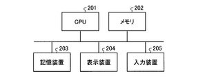
- FIG. 19 is a diagram showing a hardware configuration when a part of the functions of the logging unit 110, the client 140 or the server 130 according to the first embodiment is realized by a computer.
- a part of the functions of the logging unit 110, the client 140 or the server 130 is realized by a computer
- a part of the functions of the logging unit 110, the client 140 or the server 130 are CPU (Central Processing Unit) 201 as shown in FIG.
- the memory 202, the storage device 203, the display device 204, and the input device 205 Some of the functions of the logging unit 110, the client 140, or the server 130 are realized by software, firmware, or a combination of software and firmware.
- the software or firmware is described as a program and stored in the storage device 203.
- the CPU 201 realizes a part of the functions of the logging unit 110, the client 140 or the server 130 by reading out software or firmware stored in the storage device 203 into the memory 202 and executing the software or firmware. That is, the step in which the logging unit 110, the client 140 or the server 130 implements a part of the functions of the logging unit 110, the client 140 or the server 130 when the part of their functions is executed by the computer results in A storage device 203 is provided for storing the program to be executed. In addition, it can be said that these programs cause a computer to execute processing realized by part of the functions of the logging unit 110, the client 140 or the server 130.
- the memory 202 corresponds to a volatile storage area such as a random access memory (RAM).
- the storage device 203 corresponds to a non-volatile or volatile semiconductor memory such as a read only memory (ROM), a flash memory, or a magnetic disk.
- ROM read only memory
- the display device 204 are a monitor and a display.
- the display unit 143 of the client 140 is realized by the display device 204.
- Specific examples of the input device 205 are a keyboard, a mouse, and a touch panel.
- the configuration shown in the above embodiment shows an example of the contents of the present invention, and can be combined with another known technique, and one of the configurations is possible within the scope of the present invention. Parts can be omitted or changed.
Abstract
This monitoring device (130) is provided with a path data creation unit (131) that acquires information regarding three-dimensional coordinates for each of times indicating the operation state of factory equipment and uses the three-dimensional coordinates for each time and a received reproduction instruction as a basis to create path data in which commands are recorded regarding how information from an image indicating the operation state of the factory equipment is to be combined with three-dimensional coordinates and displayed.
Description
本発明は、工場設備の保守のための監視装置、監視システムおよび監視方法に関する。
The present invention relates to a monitoring device, a monitoring system and a monitoring method for maintenance of factory equipment.
従来の監視カメラからなる監視装置は、監視カメラの一方向からの録画になる為、監視カメラの死角となる製造現場の詳細な動作については再生することが不可能であり、ロボットといった製造装置にトラブルが発生したときの原因特定に時間がかかるまたは原因特定が困難であるという問題があった。また、監視装置からトラブルを通知されても、トラブルを解決するために、ユーザが製造現場に行ってトラブルを再現および確認して、原因を特定する必要があった。
Since the monitoring apparatus consisting of the conventional surveillance camera is recording from one direction of the surveillance camera, it is impossible to reproduce the detailed operation of the manufacturing site which becomes the blind spot of the surveillance camera, and the manufacturing apparatus such as a robot There was a problem that it took time to identify the cause when trouble occurred or it was difficult to identify the cause. In addition, even if a trouble is notified from the monitoring device, in order to solve the trouble, the user needs to go to the manufacturing site, reproduce and confirm the trouble, and identify the cause.
特許文献1においては、2台のロボット制御装置と1台のモニタ装置とを接続して、2台のロボットの動作状況を1つのモニタ装置の表示画面にリアルタイムに描画することで、ロボットの動作状況を再現するシステムが提案されている。具体的には、モニタ装置は通信ネットワークを介して周期的にロボットの関節角の現在値をロボット制御装置上の関節角サーバから収集し、ロボットの描画データを更新している。
In Patent Document 1, two robot control devices and one monitor device are connected, and the operation states of the two robots are drawn in real time on the display screen of one monitor device, whereby the robot operation is performed. Systems have been proposed to reproduce the situation. Specifically, the monitoring device periodically collects the current value of the joint angle of the robot from the joint angle server on the robot control device via the communication network, and updates the drawing data of the robot.
しかし、特許文献1のシステムは、ロボットの動作状況をモニタすることを目的としており、ロボットの関節角の現在値のみを収集してシミュレーションを実行している。したがって、関節角の現在値を用いてロボットのシミュレーションを再確認することは出来ても、ベルトコンベア上の搬送物とロボットとの衝突といった設備稼働状況下でのトラブルをリアルにシミュレーションすることはできず、シミュレーションを活用してトラブルの対策をすることは出来なかった。
However, the system of Patent Document 1 aims to monitor the operation state of the robot, and only the current value of the joint angle of the robot is collected to execute the simulation. Therefore, although it is possible to reconfirm the robot simulation using the current value of the joint angle, it is possible to realistically simulate the trouble under the facility operating condition such as the collision between the transported object on the belt conveyor and the robot. No, I could not use the simulation to take measures against the problem.
本発明は、上記に鑑みてなされたものであって、製造装置を含む工場設備の稼働状況を模擬することを可能にする監視装置を得ることを目的とする。
The present invention has been made in view of the above, and it is an object of the present invention to obtain a monitoring device that makes it possible to simulate the operating condition of factory equipment including a manufacturing device.
上述した課題を解決し、目的を達成するために、本発明は、工場設備の稼働状況を示す時刻毎の3次元座標の情報を取得する。本発明は、時刻毎の3次元座標および受け付けた再生の指示に基づいて、工場設備の稼働状況を示す画像の情報を3次元座標にどのように組み合わせて表示するかについての指令を記述する軌跡データを作成する軌跡データ作成部を備えることを特徴とする。
In order to solve the problems described above and to achieve the object, the present invention acquires information of three-dimensional coordinates at each time indicating the operation status of factory equipment. The present invention is a locus that describes a command on how to combine information of an image showing the operation status of factory equipment with three-dimensional coordinates based on the three-dimensional coordinates for each time and the received reproduction instruction. A trajectory data generation unit for generating data is provided.
本発明にかかる監視装置は、製造装置を含む工場設備の稼働状況を模擬することが可能になるという効果を奏する。
ADVANTAGE OF THE INVENTION The monitoring apparatus concerning this invention has an effect that it becomes possible to simulate the working condition of the factory installation containing a manufacturing apparatus.
以下に、本発明の実施の形態にかかる監視装置、監視システムおよび監視方法を図面に基づいて詳細に説明する。なお、この実施の形態によりこの発明が限定されるものではない。
Hereinafter, a monitoring device, a monitoring system, and a monitoring method according to an embodiment of the present invention will be described in detail based on the drawings. The present invention is not limited by the embodiment.
実施の形態1.
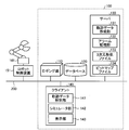
図1は、本発明の実施の形態1にかかる工場設備1の構成を示すブロック図である。実施の形態1にかかる工場設備1は、製造ラインとなる搬送装置であるベルトコンベア190と、製造装置であるロボット161,162と、製造装置の制御装置であるロボット制御装置151,152と、を備える。ベルトコンベア190により搬送物であるワーク170が搬送される。図1では、工場設備1が扱うワーク170として自動車の例が示されている。ワーク170に対して作業を行うロボット161,162には、それぞれを制御するロボット制御装置151,152が接続されている。工場設備1には、さらに、ワーク170の位置を検出するセンサ180と、ロボット161の温度を検出するセンサ181と、ロボット162の温度を検出するセンサ182と、が設けられている。ロボット161,162の温度とは、具体的には、ロボット161,162を構成するロボットアームの各関節に相当する各軸の温度である。ロボット制御装置151,152、センサ180,181,182およびベルトコンベア190はネットワーク200に接続されている。なお、ネットワーク200は、有線または無線のいずれであってもかまわない。Embodiment 1
FIG. 1 is a block diagram showing the configuration of afactory installation 1 according to a first embodiment of the present invention. The factory facility 1 according to the first embodiment includes a belt conveyor 190 which is a transfer device serving as a production line, robots 161 and 162 which are production devices, and robot control devices 151 and 152 which are control devices for production devices Prepare. A workpiece 170 which is a conveyed object is conveyed by the belt conveyor 190. In FIG. 1, an example of a car is shown as a work 170 handled by the factory facility 1. The robot control devices 151 and 152 which control each are connected to the robots 161 and 162 which operate | work with respect to the workpiece | work 170, respectively. The factory facility 1 further includes a sensor 180 that detects the position of the workpiece 170, a sensor 181 that detects the temperature of the robot 161, and a sensor 182 that detects the temperature of the robot 162. Specifically, the temperature of each of the robots 161 and 162 is the temperature of each axis corresponding to each joint of the robot arms constituting the robots 161 and 162. The robot control devices 151 and 152, the sensors 180, 181 and 182, and the belt conveyor 190 are connected to the network 200. The network 200 may be wired or wireless.
図1は、本発明の実施の形態1にかかる工場設備1の構成を示すブロック図である。実施の形態1にかかる工場設備1は、製造ラインとなる搬送装置であるベルトコンベア190と、製造装置であるロボット161,162と、製造装置の制御装置であるロボット制御装置151,152と、を備える。ベルトコンベア190により搬送物であるワーク170が搬送される。図1では、工場設備1が扱うワーク170として自動車の例が示されている。ワーク170に対して作業を行うロボット161,162には、それぞれを制御するロボット制御装置151,152が接続されている。工場設備1には、さらに、ワーク170の位置を検出するセンサ180と、ロボット161の温度を検出するセンサ181と、ロボット162の温度を検出するセンサ182と、が設けられている。ロボット161,162の温度とは、具体的には、ロボット161,162を構成するロボットアームの各関節に相当する各軸の温度である。ロボット制御装置151,152、センサ180,181,182およびベルトコンベア190はネットワーク200に接続されている。なお、ネットワーク200は、有線または無線のいずれであってもかまわない。
FIG. 1 is a block diagram showing the configuration of a
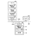
工場設備1には、ロボット161,162およびワーク170の状態を監視する監視システム100が設けられている。監視システム100は、ロギング機能を有するロギング部110と、記憶装置に保持されるデータベース120と、監視装置であるサーバ130と、工場設備1の動作を模擬する動画を表示するクライアント装置であるクライアント140と、を備える。クライアント140は、工場設備1の3次元形状の動作をシミュレートして表示する。ロギング部110、データベース120、サーバ130およびクライアント140はネットワーク200に接続されている。ロギング部110、サーバ130およびクライアント140はコンピュータにより実現される。ロギング部110およびサーバ130は、それぞれ別個のコンピュータにより実現されてもよいが、1つのコンピュータによって両者の機能が実現されてもよい。クライアント140は、サーバ130から取得したデータに基づいて工場設備1における製造現場の3次元形状の動作を模擬して表示する。
The factory installation 1 is provided with a monitoring system 100 that monitors the states of the robots 161 and 162 and the work 170. The monitoring system 100 includes a logging unit 110 having a logging function, a database 120 held in a storage device, a server 130 that is a monitoring device, and a client device 140 that is a client device that displays moving images that simulate the operation of the factory facility 1. And. The client 140 simulates and displays the operation of the three-dimensional shape of the factory facility 1. The logging unit 110, the database 120, the server 130 and the client 140 are connected to the network 200. The logging unit 110, the server 130 and the client 140 are realized by a computer. The logging unit 110 and the server 130 may be realized by separate computers, but one computer may realize the functions of both. The client 140 simulates and displays the operation of the three-dimensional shape of the manufacturing site in the plant facility 1 based on the data acquired from the server 130.
ネットワーク200を介して、ロギング部110は、製造装置を含む工場設備1の稼働状況を示す時刻毎の3次元座標の情報を取得する。工場設備1にはロボット161,162に加えてベルトコンベア190も含まれ、工場設備1の稼働状況にはワーク170の状況も含まれる。したがって、ロギング部110は、具体的には、ロボット161,162の各軸の位置および角度、ベルトコンベア190の速度、ワーク170の位置といったデータを時刻の情報と共に一定周期で収集する。ロギング部110は収集した上記データをネットワーク200経由でデータベース120に転送し、データベース120に保存する。サーバ130はデータベース120にアクセスして必要なデータを取得する。クライアント140は、製造装置および製造ラインの再生動作のために必要なデータをサーバ130に要求する。
Through the network 200, the logging unit 110 acquires information of three-dimensional coordinates for each time indicating the operation status of the factory facility 1 including the manufacturing apparatus. The factory equipment 1 includes the belt conveyor 190 in addition to the robots 161 and 162, and the operation status of the factory equipment 1 also includes the situation of the workpiece 170. Therefore, specifically, the logging unit 110 collects data such as the position and angle of each axis of the robots 161 and 162, the speed of the belt conveyor 190, the position of the workpiece 170, and the time information at a constant cycle. The logging unit 110 transfers the collected data to the database 120 via the network 200 and stores the data in the database 120. The server 130 accesses the database 120 to acquire necessary data. The client 140 requests the server 130 for data necessary for the reproduction operation of the manufacturing apparatus and the manufacturing line.
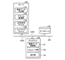
図2は、実施の形態1にかかる監視システム100の詳細な構成を示すブロック図である。図3は、実施の形態1にかかるロギング部110の動作を説明するフローチャートである。なお、図2は、簡単のため図1の構成要素の一部の記載を省いてある。
FIG. 2 is a block diagram showing the detailed configuration of the monitoring system 100 according to the first embodiment. FIG. 3 is a flowchart for explaining the operation of the logging unit 110 according to the first embodiment. Note that FIG. 2 omits some of the components of FIG. 1 for the sake of simplicity.
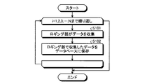
ここで、ロギング部110が情報を収集する周期を単位にしたときに、工場設備1の稼働期間がN周期であるとする。定められたタイミングで、ロギング部110は、ロボット制御装置151,152、ベルトコンベア190およびセンサ180,181,182からデータを収集する(ステップS101)。具体的には、ロギング部110は、ロボット制御装置151,152からのロボット161,162の各軸の位置および角度、ベルトコンベア190からのベルトコンベア190の速度、センサ180からのワーク170の位置、センサ181,182からのロボット161,162の温度といったデータを時刻の情報と共にネットワーク200を介して収集する。さらに、ロギング部110がネットワーク200を介して収集するデータには、ロボット161,162の各軸の動きの速度、製造ラインおよび製造装置が設置されている製造現場の温度が含まれていてもよい。
Here, it is assumed that the operation period of the plant facility 1 is N cycles when the cycle in which the logging unit 110 collects information is taken as a unit. At a defined timing, the logging unit 110 collects data from the robot control devices 151 and 152, the belt conveyor 190, and the sensors 180, 181 and 182 (step S101). Specifically, the logging unit 110 is a position and an angle of each axis of the robot 161, 162 from the robot control device 151, 152, a speed of the belt conveyor 190 from the belt conveyor 190, a position of the work 170 from the sensor 180, Data such as the temperatures of the robots 161 and 162 from the sensors 181 and 182 are collected via the network 200 together with time information. Furthermore, the data collected by the logging unit 110 via the network 200 may include the speed of movement of each axis of the robots 161 and 162, the temperature of the manufacturing line and the manufacturing site where the manufacturing apparatus is installed. .
そして、ロギング部110は、収集した上記データを時刻毎にデータベース120に保存する(ステップS102)。ロギング部110は、i=1,2,3,・・・,Nとi=1からi=NになるまでステップS101およびステップS102をN回繰り返す。これにより、ロギング部110は、一定周期毎のロボット161,162の各軸の位置および角度、ベルトコンベア190の速度、ワーク170の位置およびロボット161,162の温度を取得して時刻の情報と共にデータベース120に保存することができる。なお、あるタイミングで収集したデータの値と当該タイミングの1周期前に収集した値との差分の絶対値が、定められた値より大きい場合は、ロギング部110は、当該タイミングで収集したデータにはノイズが重畳していると判断して、当該データは破棄してデータベース120に保存しない。
Then, the logging unit 110 saves the collected data in the database 120 for each time (step S102). The logging unit 110 repeats steps S101 and S102 N times until i = 1, 2, 3,..., N and i = 1 to i = N. As a result, the logging unit 110 acquires the position and angle of each axis of the robots 161 and 162, the speed of the belt conveyor 190, the position of the workpiece 170 and the temperature of the robots 161 and 162 for each fixed cycle, and the database together with time information It can be stored at 120. If the absolute value of the difference between the value of the data collected at a certain timing and the value collected one cycle before the relevant timing is larger than a predetermined value, the logging unit 110 uses the data collected at the relevant timing. Determines that noise is superimposed, the data is discarded and the data is not stored in the database 120.
サーバ130は、クライアント140の要求に応じて工場設備1の3次元形状の軌跡にかかる軌跡データを作成する軌跡データ作成部131と、アラーム情報を取得してクライアント140に通知するアラーム監視部132と、データベース120から取得した情報に基づく3次元形状ファイル133と、画像データであるビットマップファイル134と、を備える。軌跡データ作成部131は、軌跡データを含んだスクリプトまたはスクリプトファイルを作成する。後述するように、スクリプトは軌跡データ以外のデータも記載されているデータファイルであるが、スクリプトファイルには軌跡データしか記載されていない。
The server 130 generates a locus data generation unit 131 that generates locus data relating to a locus of the three-dimensional shape of the plant facility 1 in response to a request from the client 140, and an alarm monitoring unit 132 that acquires alarm information and notifies the client 140. And a three-dimensional shape file 133 based on the information acquired from the database 120, and a bitmap file 134 which is image data. The locus data creation unit 131 creates a script or script file including locus data. As described later, a script is a data file in which data other than trajectory data is also described, but only trajectory data is described in the script file.
3次元形状ファイル133は、製造装置を含む工場設備1の稼働状況を示す3次元座標の情報を有するファイルである。3次元形状ファイル133は、具体的には、ロボット161,162の各軸の3次元空間上の位置のデータおよびベルトコンベア190上のワーク170の3次元空間上の位置のデータを含んだデータである。3次元形状ファイル133はロボット161,162およびワーク170を3次元空間上で表示するための骨格または輪郭となる点群の3次元座標の情報を含んでいる。上述したように、ロボット161,162の各軸の3次元座標のデータは、ロボット制御装置151,152が有しているロボット161,162の制御プログラムからロギング部110が取得してデータベース120に一定周期で時刻の情報と共に保存されている。また、ベルトコンベア190上のワーク170の3次元座標のデータは、センサ180またはベルトコンベア190からロギング部110が取得してデータベース120に一定周期で時刻と共に保存されている。クライアント140はデータベース120にアクセスして、データベース120に保存されているこれらのデータに基づいて、時刻毎の3次元形状ファイル133を作成して自らの記憶装置に保存してゆく。3次元形状ファイル133のファイル形式はAutoCAD(登録商標)、SOLIDWORKS(登録商標)またはiCAD(登録商標)のデータフォーマットに準拠しているので、3次元形状ファイル133はAutoCAD(登録商標)、SOLIDWORKS(登録商標)またはiCAD(登録商標)により読み取り可能である。したがって、3次元形状ファイル133のファイル形式は、3次元ファイル形式であるParasolid、IGES(Initial Graphics Exchange Specification)、STEP、STL(Standard Triangulated Language)、VPS、VRML(Virtual Reality Modeling Language)、CATIA V5(Computer graphics Aided Three dimensional Interactive Application V5)、Pro/E、NX、I-deasまたはJTといったファイル形式であってもよい。また、3次元形状ファイル133のファイル形式は、上記したような既存の形式に限定されず、独自なまたは新たなファイル形式であってもかまわない。
The three-dimensional shape file 133 is a file having information of three-dimensional coordinates indicating the operating status of the factory equipment 1 including the manufacturing apparatus. Specifically, the three-dimensional shape file 133 is data including the data of the position of each axis of the robots 161 and 162 in the three-dimensional space and the data of the position of the workpiece 170 on the belt conveyor 190 in the three-dimensional space. is there. The three-dimensional shape file 133 contains information of three-dimensional coordinates of a skeleton or a point group to be an outline for displaying the robots 161 and 162 and the workpiece 170 in three-dimensional space. As described above, the data of the three-dimensional coordinates of each axis of the robots 161 and 162 is acquired by the logging unit 110 from the control program of the robots 161 and 162 possessed by the robot control devices 151 and 152 and fixed in the database 120 It is stored with the time information in a cycle. Further, the data of the three-dimensional coordinates of the workpiece 170 on the belt conveyor 190 is acquired by the logging unit 110 from the sensor 180 or the belt conveyor 190 and stored in the database 120 along with the time at a constant cycle. The client 140 accesses the database 120, and based on the data stored in the database 120, creates the three-dimensional shape file 133 for each time and saves it in its own storage device. Since the file format of the three-dimensional shape file 133 conforms to the data format of AutoCAD (registered trademark), SOLIDWORKS (registered trademark) or iCAD (registered trademark), the three-dimensional shape file 133 is AutoCAD (registered trademark), SOLIDWORKS (registered trademark) It is readable by registered trademark) or iCAD (registered trademark). Therefore, the file format of the three-dimensional shape file 133 is three-dimensional file format Parasolid, Initial Graphics Exchange Specification (IGES), STEP, Standard Triangulated Language (STEP), VPS, Virtual Reality Modeling Language (VRML), CATIA V5 ( It may be a file format such as Computer graphics Aided Three dimensional Interactive Application V5), Pro / E, NX, I-deas or JT. Also, the file format of the three-dimensional shape file 133 is not limited to the existing format as described above, and may be a unique or new file format.
ビットマップファイル134は、製造装置を含む工場設備1の稼働状況を示す画像の情報を有するファイルである。ビットマップファイル134は、具体的には、3次元形状ファイル133が示す骨格または輪郭に肉付けして3次元空間におけるロボット161,162およびワーク170を作画するために必要となるロボット161,162およびワーク170の画像の情報を示すファイルである。すなわち、ビットマップファイル134は、3次元形状ファイル133が示す点群に沿って3次元空間上で貼り付ける画像の情報である。ビットマップファイル134のファイル形式はAutoCAD(登録商標)、SOLIDWORKS(登録商標)またはiCAD(登録商標)のデータフォーマットに準拠しているので、ビットマップファイル134はAutoCAD(登録商標)、SOLIDWORKS(登録商標)またはiCAD(登録商標)により読み取り可能である。したがって、ビットマップファイル134のファイル形式は、DXF(Drawing Exchange Format)、DWG、ME-10、IGES、MicroCADAM図面、DMNDOS、MCDまたはBMIといったファイル形式であってもよい。なお、DWGは、AutoCAD(登録商標)の標準ファイル形式である。また、ビットマップファイル134のファイル形式は、上記したような既存の形式に限定されず、独自なまたは新たなファイル形式であってもかまわない。
The bit map file 134 is a file having image information indicating the operating status of the factory facility 1 including the manufacturing apparatus. Specifically, the bit map file 134 is a robot 161, 162 and a work required to draw the robot 161, 162 and the work 170 in the three-dimensional space by adding to the skeleton or outline indicated by the three-dimensional shape file 133. It is a file which shows the information of 170 images. That is, the bitmap file 134 is information of an image to be pasted on the three-dimensional space along the point group indicated by the three-dimensional shape file 133. Since the file format of the bitmap file 134 conforms to the data format of AutoCAD (registered trademark), SOLIDWORKS (registered trademark) or iCAD (registered trademark), the bitmap file 134 is AutoCAD (registered trademark), SOLIDWORKS (registered trademark) Or iCAD (registered trademark). Therefore, the file format of the bitmap file 134 may be a file format such as DXF (Drawing Exchange Format), DWG, ME-10, IGES, MicroCADAM drawing, DMNDOS, MCD or BMI. DWG is a standard file format of AutoCAD (registered trademark). Further, the file format of the bitmap file 134 is not limited to the existing format as described above, and may be a unique or new file format.
クライアント140は、サーバ130から取得したスクリプトまたはスクリプトファイルに含まれる軌跡データを解釈する軌跡データ解釈部141と、軌跡データ解釈部141の解釈結果に基づいて工場設備1の3次元形状の動作シミュレーションを実行するシミュレータ部142と、シミュレータ部142による3次元形状の動作シミュレーションの結果を表示する表示部143と、を備える。
The client 140 simulates the operation of the three-dimensional shape of the factory facility 1 based on the interpretation result of the locus data interpretation unit 141 that interprets the locus data included in the script or script file acquired from the server 130 and the locus data interpretation unit 141. A simulator unit 142 to be executed and a display unit 143 for displaying the result of the operation simulation of the three-dimensional shape by the simulator unit 142 are provided.
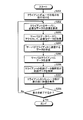
図4は、実施の形態1にかかるクライアント140およびサーバ130の処理を説明するフローチャートである。図5は、実施の形態1にかかる「リアルタイム再生」を説明する図である。図6は、実施の形態1にかかる「通常再生」を説明する図である。図7は、実施の形態1にかかる「逆再生」を説明する図である。図8は、実施の形態1にかかるクライアント140およびサーバ130の処理の流れを説明する図である。図9は、実施の形態1にかかるクライアント140およびサーバ130の処理の流れを説明する別の図である。図10は、実施の形態1にかかるスクリプトの構成を示す図である。図11は、実施の形態1にかかるスクリプト関連ファイルの構成を示す図である。図12は、実施の形態1にかかる「通常再生」の実行を説明する図である。図13は、実施の形態1にかかる「逆再生」の実行を説明する図である。図14は、実施の形態1にかかる「通常再生」の実行中の表示部の画面を示す図である。
FIG. 4 is a flowchart illustrating processing of the client 140 and the server 130 according to the first embodiment. FIG. 5 is a diagram for explaining “real time reproduction” according to the first embodiment. FIG. 6 is a diagram for explaining “normal reproduction” according to the first embodiment. FIG. 7 is a diagram for explaining “reverse reproduction” according to the first embodiment. FIG. 8 is a diagram for explaining the process flow of the client 140 and the server 130 according to the first embodiment. FIG. 9 is another diagram illustrating the process flow of the client 140 and the server 130 according to the first embodiment. FIG. 10 is a diagram showing the configuration of a script according to the first embodiment. FIG. 11 is a diagram showing the configuration of a script related file according to the first embodiment. FIG. 12 is a diagram for explaining the execution of the “normal reproduction” according to the first embodiment. FIG. 13 is a diagram for explaining the execution of “reverse reproduction” according to the first embodiment. FIG. 14 is a diagram of a screen of the display unit during execution of “normal playback” according to the first embodiment.
以下に、実施の形態1にかかるクライアント140およびサーバ130の処理を説明する。
The processes of the client 140 and the server 130 according to the first embodiment will be described below.
まず、ユーザは再生または逆再生のいずれかを指示し、クライアント140の入力装置がユーザの指示を受け付ける(図4、ステップS201)。具体的には、ユーザは「リアルタイム再生」、「通常再生」または「逆再生」のいずれかを指示し、クライアント140の入力装置はいずれかの指示を受け付ける。
First, the user instructs either playback or reverse playback, and the input device of the client 140 receives the user's instruction (FIG. 4, step S201). Specifically, the user instructs one of “real-time reproduction”, “normal reproduction”, and “reverse reproduction”, and the input device of the client 140 receives any instruction.
ユーザが「リアルタイム再生」を指示する場合は、現在以降の工場設備1の3次元形状の動作を再生することを望む場合である。現在時刻が16:00の場合、ユーザは、図5に示すような再生を望んでいる。
In the case where the user instructs "real time reproduction", it is a case where it is desired to reproduce the operation of the three-dimensional shape of the plant facility 1 after the present. If the current time is 16:00, the user desires playback as shown in FIG.
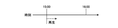
ユーザが「通常再生」を指示する場合は、ユーザが希望する過去の再生時刻からの工場設備1の3次元形状の動作を再生することを望む場合なので、再生時刻を共に指定することになる。現在時刻が16:00で、再生時刻として15:00が指定された場合、ユーザは、図6に示すような再生を望んでいる。
In the case where the user instructs “normal reproduction”, it is a case where it is desired to reproduce the operation of the three-dimensional shape of the factory facility 1 from the past reproduction time desired by the user, so both reproduction times are specified. If the current time is 16:00 and 15:00 is specified as the playback time, the user desires playback as shown in FIG.
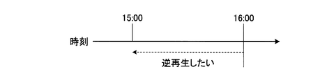
ユーザが「逆再生」を指示する場合は、ユーザが希望する逆再生時刻からの工場設備1の3次元形状の動作を逆再生することを望む場合なので、逆再生時刻を共に指定することになる。現在時刻および逆再生時刻が共に16:00の場合、ユーザは、図7に示すような逆再生を望んでいる。
In the case where the user instructs "reverse playback", when it is desired to reverse play the operation of the three-dimensional shape of the factory facility 1 from the reverse playback time desired by the user, both the reverse playback times are specified . If the current time and the reverse playback time are both 16:00, the user desires reverse playback as shown in FIG.
ステップS201の後、クライアント140はサーバ130に、必要なデータの送信を要求する(図4、図8、ステップS202)。このとき、クライアント140は、ステップS201において受け付けた「リアルタイム再生」、「通常再生」または「逆再生」のいずれかの指示および当該指示に応じて定められている期間をサーバ130に通知すると共に、当該期間分のデータの送信をサーバ130に要求する。指示に応じて定められている期間は、「リアルタイム再生」、「通常再生」または「逆再生」においてデータ転送の纏まりとなるデータの時間の単位となっている。なお、サーバ130が「リアルタイム再生」、「通常再生」または「逆再生」に応じて定められている期間を当初から保持していてもかまわない。定められている期間の具体例は、「リアルタイム再生」の場合は1秒、「通常再生」または「逆再生」の場合は5秒といった期間である。そして、クライアント140が「リアルタイム再生」、「通常再生」または「逆再生」のいずれを受け付けた場合であっても、ステップS202から後述するステップS207までは上記定められている期間に基づいて定期的に繰り返し実行されることになるので、ステップS202のクライアント140からサーバ130への要求も定期的に実行されることになる。
After step S201, the client 140 requests the server 130 to transmit necessary data (FIG. 4, FIG. 8, step S202). At this time, the client 140 notifies the server 130 of the “real-time playback”, “normal playback” or “reverse playback” instruction accepted in step S 201 and the period determined according to the instruction to the server 130, The server 130 is requested to transmit data for the period. The period determined in accordance with the instruction is a unit of time of data which is a group of data transfer in “real time reproduction”, “normal reproduction” or “reverse reproduction”. Note that the server 130 may initially hold a period determined in accordance with “real time reproduction”, “normal reproduction”, or “reverse reproduction”. A specific example of the defined period is a period of 1 second in the case of "real time reproduction", or 5 seconds in the case of "normal reproduction" or "reverse reproduction". Then, even when the client 140 receives any of “real time reproduction”, “normal reproduction”, and “reverse reproduction”, the process from step S202 to step S207 described later is performed periodically based on the above-mentioned determined period. The request from the client 140 to the server 130 in step S202 will also be periodically executed.
クライアント140からの要求を受け付けたサーバ130は、データベース120にアクセスして、必要なデータを取得する(図4、図8、図9、ステップS203)。必要なデータは、ロボット161,162を含む工場設備1の稼働状況を示す時刻毎の3次元座標の情報である。必要なデータには、サーバ130が3次元形状ファイル133を作成するために必要なロボット161,162の各軸の3次元空間上の時刻毎の位置のデータおよびベルトコンベア190上のワーク170の3次元空間上の時刻毎の位置のデータが含まれている。必要なデータには、さらにベルトコンベア190の時刻毎の速度のデータが含まれる。また、ステップS203でサーバ130がデータベース120から取得するデータには、時刻毎のロボット161,162の温度、時刻毎のロボット161,162の各軸の角度、各軸の動きの速度、時刻毎の製造現場の温度が含まれていてもよい。そして、ステップS203でサーバ130がデータベース120から取得するデータは、上述したようにクライアント140が受け付けた「リアルタイム再生」、「通常再生」または「逆再生」の指示に応じて定められている期間分のデータである。
The server 130 having received the request from the client 140 accesses the database 120 and acquires necessary data (FIG. 4, FIG. 8, FIG. 9, step S203). The necessary data is information of three-dimensional coordinates at each time indicating the operation status of the factory facility 1 including the robots 161 and 162. Necessary data include data of the position of each time on the three-dimensional space of each axis of the robots 161 and 162 necessary for the server 130 to create the three-dimensional shape file 133 and three of the work 170 on the belt conveyor 190. The data of the position for each time in the dimensional space is included. The necessary data further includes data of the speed of the belt conveyor 190 at each time. Further, the data acquired by the server 130 from the database 120 in step S203 includes the temperature of the robots 161 and 162 for each time, the angle of each axis of the robots 161 and 162 for each time, the speed of movement of each axis, and each time The temperature at the manufacturing site may be included. Then, the data acquired by the server 130 from the database 120 in step S203 is for a period determined according to the “real time reproduction”, “normal reproduction” or “reverse reproduction” received by the client 140 as described above. Data of
次に、サーバ130はデータベース120から取得したデータを用いて、クライアント140に送信するデータを作成する(図4、ステップS204)。具体的には、サーバ130は、先に説明したように、データベース120から取得したロボット161,162の各軸の3次元空間上の位置のデータおよびベルトコンベア190上のワーク170の3次元空間上の位置のデータに基づいて、時刻毎の3次元形状ファイル133を作成する。さらに、サーバ130の軌跡データ作成部131は、クライアント140が受け付けた「リアルタイム再生」、「通常再生」または「逆再生」のいずれかの指示、当該指示に応じて定められている期間および作成した3次元形状ファイル133に基づいて、時刻毎の3次元形状ファイル133の点群が示す3次元座標にビットマップファイル134の画像をどのように組み合わせて、時系列に沿って連続して表示するかについての指令を記述する軌跡データを作成する。サーバ130による軌跡データの作成に際しては、サーバ130はロボット161,162の各軸の角度、各軸の動きの速度を参照してもよい。サーバ130の軌跡データ作成部131はロボット161,162の各軸の角度、各軸の動きの速度を参照することで、ロボット161,162の各軸の動きをより忠実に再現した軌跡データを作成することができる。また、軌跡データ作成部131は時刻毎の製造現場の温度を参照することにより、温度によるロボット161,162への影響を考慮した軌跡データを作成することができる。
Next, the server 130 uses the data acquired from the database 120 to create data to be transmitted to the client 140 (FIG. 4, step S204). Specifically, as described above, the server 130 is data on the positions of the axes of the robots 161 and 162 in the three-dimensional space acquired from the database 120 and on the three-dimensional space of the workpiece 170 on the belt conveyor 190. The three-dimensional shape file 133 for each time is created based on the data of the position of. Furthermore, the locus data creation unit 131 of the server 130 creates a command that is received by the client 140 for “real-time playback”, “normal playback”, or “reverse playback”, and a period that is set according to the instruction How is the image of the bitmap file 134 combined with the three-dimensional coordinates indicated by the point group of the three-dimensional shape file 133 for each time based on the three-dimensional shape file 133 and displayed continuously in time series? Create trajectory data that describes the command for. When creating trajectory data by the server 130, the server 130 may refer to the angle of each axis of the robots 161 and 162 and the speed of movement of each axis. The locus data creation unit 131 of the server 130 creates locus data that more faithfully reproduces the movement of each axis of the robots 161 and 162 by referring to the angle of each axis of the robots 161 and 162 and the movement speed of each axis. can do. Further, the trajectory data creation unit 131 can create trajectory data in consideration of the influence of the temperature on the robots 161 and 162 by referring to the temperature of the manufacturing site at each time.
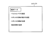
サーバ130が軌跡データをクライアント140に送信するに際しては、軌跡データ作成部131が、図10に示すように1つのデータファイルであるスクリプトを作成する。図10のスクリプトには、軌跡データの内容が記載されていると共に、ベルトコンベア190の速度、さらにはロボット161,162の各軸の動きの速度、ロボット161,162の各軸の温度、製造現場の温度といった情報が追記されている。すなわち、スクリプトには、クライアント140が工場設備1の稼働状況をシミュレーションする為に必要な情報が含まれている。
When the server 130 transmits trajectory data to the client 140, the trajectory data creation unit 131 creates a script that is one data file as shown in FIG. The script in FIG. 10 describes the contents of the locus data, and also the speed of the belt conveyor 190, the speed of movement of each axis of the robots 161, 162, the temperature of each axis of the robots 161, 162, the manufacturing site Information such as the temperature of is added. That is, the script contains the information necessary for the client 140 to simulate the operating condition of the plant facility 1.
なお、サーバ130が軌跡データをクライアント140に送信するに際して、軌跡データとベルトコンベア190の速度といった情報を別々のファイルで送信してもよい。具体的には、図11に示すように、軌跡データはスクリプトファイルに記載され、ベルトコンベア190の速度、さらにはロボット161,162の各軸の動きの速度が速度ファイルに記載され、ロボット161,162の各軸の温度および製造現場の温度が温度ファイルに記載されている。サーバ130の軌跡データ作成部131は軌跡データのみが記載されたスクリプトファイルを作成する。サーバ130は、さらにデータベース120から取得したデータを用いて、速度ファイルおよび温度ファイルを作成する。スクリプト関連ファイルにおいては、軌跡データを含んだスクリプトファイルとデータベース120から得た情報を含むファイルとが分けられているが、スクリプトファイル以外のファイルの構成は図11に示した構成に限定されない。
Note that, when the server 130 transmits the trajectory data to the client 140, information such as the trajectory data and the speed of the belt conveyor 190 may be transmitted as separate files. Specifically, as shown in FIG. 11, the locus data is described in a script file, the speed of the belt conveyor 190, and further, the speed of movement of each axis of the robots 161 and 162 are described in the speed file. The temperature of each axis of 162 and the temperature at the manufacturing site are described in the temperature file. The locus data creation unit 131 of the server 130 creates a script file in which only locus data is described. The server 130 further uses the data acquired from the database 120 to create a velocity file and a temperature file. In the script related file, a script file containing trajectory data and a file containing information obtained from the database 120 are divided, but the configuration of files other than the script file is not limited to the configuration shown in FIG.
そして、サーバ130はクライアント140にデータを送信する(図4、図9、ステップS205)。サーバ130からクライアント140にデータを送信する第一の方法では、定められている期間分の時刻毎の3次元形状ファイル133と、ビットマップファイル134と、図10に示すスクリプトと、をサーバ130からクライアント140に送信する。サーバ130からクライアント140にデータを送信する第二の方法では、定められている期間分の時刻毎の3次元形状ファイル133と、ビットマップファイル134と、図11に示すスクリプトファイル、速度ファイルおよび温度ファイルと、をサーバ130からクライアント140に送信する。監視システム100は、サーバ130からクライアント140にデータを送信する方法として、上記いずれの方法を採用してもかまわない。
Then, the server 130 transmits the data to the client 140 (FIG. 4, FIG. 9, step S205). In the first method of transmitting data from the server 130 to the client 140, the three-dimensional shape file 133 for each time of the defined period, the bit map file 134, and the script shown in FIG. Send to client 140. In the second method of transmitting data from the server 130 to the client 140, the three-dimensional shape file 133 for each time of the defined period, the bit map file 134, the script file shown in FIG. 11, the speed file and the temperature The file is sent from the server 130 to the client 140. The monitoring system 100 may adopt any of the above-described methods as a method of transmitting data from the server 130 to the client 140.
サーバ130から軌跡データを含んだデータを受信したクライアント140の軌跡データ解釈部141は、軌跡データを解釈する(図4、ステップS206)。具体的には、クライアント140が受け付けた「リアルタイム再生」、「通常再生」または「逆再生」のいずれかの指示に基づいて、軌跡データ解釈部141は、スクリプトまたはスクリプトファイルに含まれる軌跡データを解釈して、時刻毎の3次元形状ファイル133の点群が示す3次元座標にビットマップファイル134の画像を組み合わせて、時系列に沿って連続して表示するための1画面ずつの画像データを作成する。軌跡データ解釈部141は、画像データの作成に際しては、サーバ130から受信したベルトコンベア190の速度も参照する。軌跡データ解釈部141は、画像データの作成に際して、ロボット161,162の各軸の角度、各軸の動きの速度をさらに参照してもよい。また、軌跡データ解釈部141は、画像データの作成に際して、ロボット161,162の各軸の温度および製造現場の温度を、数値または色を用いて表現してもよい。以上により、軌跡データ解釈部141は、ロボット161,162のみならず、ワーク170およびベルトコンベア190も模擬した画像データを作成することができる。軌跡データ解釈部141は、「リアルタイム再生」、「通常再生」または「逆再生」の指示に応じて定められている期間内を更に細分する時間毎の画像データを連続的に表示すればロボット161,162、ワーク170およびベルトコンベア190を模擬した立体グラフィックからなる動画となるように、1画面ずつの画像データを作成する。
The locus data interpretation unit 141 of the client 140 that has received the data including the locus data from the server 130 interprets the locus data (FIG. 4, step S206). Specifically, based on the instruction of “real time reproduction”, “normal reproduction” or “reverse reproduction” accepted by the client 140, the locus data interpretation unit 141 extracts the locus data included in the script or script file. Interpret and combine the image of the bitmap file 134 with the three-dimensional coordinates indicated by the point cloud of the three-dimensional shape file 133 for each time, and display the image data of one screen each for continuous display in time series create. The locus data interpretation unit 141 also refers to the speed of the belt conveyor 190 received from the server 130 when creating image data. The trajectory data interpretation unit 141 may further refer to the angle of each axis of the robots 161 and 162 and the movement speed of each axis when creating image data. Further, when creating the image data, the locus data interpretation unit 141 may express the temperature of each axis of the robots 161 and 162 and the temperature of the manufacturing site using numerical values or colors. As described above, the trajectory data interpretation unit 141 can create image data that simulates not only the robots 161 and 162 but also the workpiece 170 and the belt conveyor 190. If the trajectory data interpretation unit 141 continuously displays image data for each time period that further divides the time period determined according to the instruction of “real time reproduction”, “normal reproduction” or “reverse reproduction”, the robot 161 , 162, and creates image data for each screen so as to be a moving image composed of a three-dimensional graphic simulating the workpiece 170 and the belt conveyor 190.
そして、クライアント140のシミュレータ部142は、軌跡データ解釈部141が作成した画像データを用いて、表示部143に映像を表示させる(図4、ステップS207)。具体的には、軌跡データ解釈部141が作成した画像データを「リアルタイム再生」、「通常再生」または「逆再生」の指示に応じて定められている期間内を更に細分する時刻毎に表示するようにシミュレータ部142が表示部143を制御することにより、「リアルタイム再生」、「通常再生」または「逆再生」の指示に応じた映像を表示部143に表示させることができる。
Then, the simulator unit 142 of the client 140 causes the display unit 143 to display an image using the image data created by the trajectory data interpretation unit 141 (FIG. 4, step S207). Specifically, the image data created by the locus data interpretation unit 141 is displayed at each time when the period defined in accordance with the instruction of “real time reproduction”, “normal reproduction” or “reverse reproduction” is further subdivided As described above, when the simulator unit 142 controls the display unit 143, it is possible to cause the display unit 143 to display an image according to the instruction of “real time reproduction”, “normal reproduction”, or “reverse reproduction”.
現在時刻が16:00である場合、「リアルタイム再生」における映像の再生は図5のように時刻に基づいて順方向に行われ、再生時刻として15:00が指定された場合の「通常再生」における映像の再生は図12のように時刻に基づいて順方向に行われる。現在時刻および逆再生時刻が共に16:00の場合の「逆再生」における映像の再生は図13のように時刻に基づいて逆方向に行われる。
When the current time is 16:00, playback of the video in “Real-time playback” is performed in the forward direction based on the time as shown in FIG. 5, and “normal playback” when 15:00 is specified as the playback time The reproduction of the image at the point is performed in the forward direction based on the time as shown in FIG. The reproduction of the video in the "reverse reproduction" when the current time and the reverse reproduction time are both 16:00 is performed in the reverse direction based on the time as shown in FIG.
図14の画面左側には、「リアルタイム再生」ボタン401、「通常再生」ボタン402および「逆再生」ボタン403が示されており、いずれかのボタンをクリックするといったユーザによる動作をクライアント140の入力装置が受け付けることによりステップS201が実行される。図14は、クライアント140の入力装置がステップS201で「通常再生」を受け付けて、ステップS207において「通常再生」を実行中の表示部143の画面の様子を示しており、軌跡データ解釈部141が作成済みの画像データがサムネイル301,・・・305,・・・,310で表示されており、バー300がサムネイル305の位置にあるので、サムネイル305の拡大画面が大画面1305として表示されている。このように、クライアント140の表示部143は、ロボット161,162の実際の動作のみならず、ワーク170およびベルトコンベア190の実際の動作も模擬して表示することが可能である。なお、映像の再生中に、ユーザがバー300を動かすことにより、バー300の移動をクライアント140の入力装置が受け付けると、シミュレータ部142は、バー300の移動先の時刻のサムネイルの拡大画面からの動画を表示部143に再生させることができる。
On the left side of the screen in FIG. 14, a “real-time playback” button 401, a “normal playback” button 402, and a “reverse playback” button 403 are shown, and an operation by the user such as clicking any button is input by the client 140. Step S201 is executed when the apparatus receives it. FIG. 14 shows the state of the screen of the display unit 143 during execution of “normal reproduction” in step S207 after the input device of the client 140 receives “normal reproduction” in step S201, and the locus data interpretation unit 141 Since the created image data is displayed as thumbnails 301,..., 305,..., 310 and the bar 300 is at the position of the thumbnail 305, the enlarged screen of the thumbnail 305 is displayed as the large screen 1305 . As described above, the display unit 143 of the client 140 can simulate and display not only the actual motions of the robots 161 and 162 but also the actual motions of the workpiece 170 and the belt conveyor 190. When the input device of the client 140 receives the movement of the bar 300 by the user moving the bar 300 during the reproduction of the video, the simulator unit 142 detects the thumbnail of the movement destination time of the bar 300 from the enlarged screen. The moving image can be reproduced on the display unit 143.
そして、クライアント140は、表示を終了するか否かを判断する(図4、ステップS208)。「逆再生」の場合において、データベース120に保存されているデータの最初の時刻までの逆再生が現在行われている場合は、クライアント140は、表示部143への映像の表示を終了すると判断して(ステップS208:Yes)、現在取得しているデータ分の逆再生が終了次第、表示を終了する。「逆再生」の場合であって上記以外の場合、「リアルタイム再生」の場合および「通常再生」の場合は、クライアント140は、表示部143への映像の表示を継続すると判断して(ステップS208:No)、ステップS202に戻って、ステップS202からステップS207までが繰り返される。
Then, the client 140 determines whether to end the display (FIG. 4, step S208). In the case of “reverse playback”, when reverse playback to the first time of data stored in the database 120 is currently being performed, the client 140 determines that the display of the video on the display unit 143 is ended. (Step S208: Yes), the display is ended as soon as the reverse reproduction for the currently acquired data is completed. In the case of “reverse playback” and other than the above, in the case of “real-time playback” and “normal playback”, the client 140 determines that the display of the video on the display unit 143 is continued (step S208 No), the process returns to step S202, and steps S202 to S207 are repeated.
なお、トラブルの原因解析をする際には、ユーザからの視点を変えて工場設備1の3次元形状の動作を再現することが望ましい。したがって、クライアント140は、表示部143に表示される映像における工場設備1の3次元形状に対する視点位置が入力装置を介して与えられた場合、すなわち3次元形状をユーザが観る方向が与えられた場合、与えられた視点位置から観た3次元形状の動作をシミュレータ部142にシミュレートさせる。これによって、シミュレータ部142は、ユーザが望む任意の視点位置から観た3次元形状の動作をシミュレートした映像を表示部143に表示させることができる。
When analyzing the cause of the trouble, it is desirable to change the viewpoint from the user to reproduce the operation of the three-dimensional shape of the plant facility 1. Therefore, in the case where the viewpoint position for the three-dimensional shape of the factory facility 1 in the video displayed on the display unit 143 is given via the input device, that is, the direction in which the user views the three-dimensional shape is given. The simulator unit 142 simulates a motion of a three-dimensional shape viewed from a given viewpoint position. As a result, the simulator unit 142 can cause the display unit 143 to display an image simulating an operation of a three-dimensional shape viewed from an arbitrary viewpoint position desired by the user.
以上のように、実施の形態1にかかるサーバ130によれば、ロボット161,162およびワーク170の動作を模擬することができる。したがって、実施の形態1にかかる監視システム100によれば、実際の製造現場におけるロボット161,162の実際の動作のみならず、ワーク170およびベルトコンベア190の実際の動作も再現表示することができる。これにより、ベルトコンベア190上のワーク170とロボット161,162との衝突といったトラブルを模擬して立体グラフィックからなる動画をクライアント140において映像表示することができる。
As described above, according to the server 130 according to the first embodiment, the operations of the robots 161 and 162 and the work 170 can be simulated. Therefore, according to the monitoring system 100 according to the first embodiment, not only the actual operations of the robots 161 and 162 at the actual manufacturing site, but also the actual operations of the workpiece 170 and the belt conveyor 190 can be reproduced and displayed. As a result, it is possible to simulate a trouble such as a collision between the workpiece 170 on the belt conveyor 190 and the robots 161 and 162, and to display an image of a moving image composed of a three-dimensional graphic on the client 140.
表示部143は、通常は、ユーザの指示に基づいて「リアルタイム再生」を実行しているが、ユーザが表示部143を常に監視しているとは限らない。製造現場においてトラブルが発生した場合、トラブルが発生した時刻の動作を再度確認したい場合がある。このような場合に、ユーザは、再生時刻と共に「通常再生」を指示または逆再生時刻と共に「逆再生」を指示したりすることができる。指示を受け付けたクライアント140は、サーバ130を経由したデータベース120から必要な情報を収集することにより、所望の時刻からの製造現場の様子を模擬した動画を時間軸上で順方向にも逆方向にも表示部143に再生させて、トラブルの発生原因を確認することが可能となる。
Although the display unit 143 normally executes “real-time reproduction” based on a user's instruction, the user is not always monitoring the display unit 143. When a problem occurs at a manufacturing site, there are cases where it is desirable to check the operation at the time of the occurrence of the problem again. In such a case, the user can instruct “normal playback” with the playback time or can issue “reverse playback” with the reverse playback time. The client 140 having received the instruction collects necessary information from the database 120 via the server 130, thereby moving the movie simulating the situation of the manufacturing site from the desired time backward in the forward direction on the time axis. It is also possible to cause the display unit 143 to reproduce and check the cause of the trouble.
そして、実施の形態1にかかる監視システム100によれば、製造現場から取得した情報を基に立体グラフィックを再生動作させることで、クライアント140において、製造現場を模擬した立体グラフィックの視点位置を変更することが容易に可能となる。したがって、従来のようにビデオカメラで製造現場を監視するのとは異なり、実施の形態1にかかる監視システム100においては、監視エリアの死角が発生しない。これにより、工場設備1の保守が容易となる上、従来のようにビデオカメラを用いて監視する場合に比べて、監視に必要な情報を大幅に削減できるので、通信量の削減にも貢献できる。
Then, according to the monitoring system 100 according to the first embodiment, the client 140 changes the viewpoint position of the three-dimensional graphic simulating the manufacturing site by reproducing the three-dimensional graphic based on the information acquired from the manufacturing site. Is easily possible. Therefore, unlike monitoring a manufacturing site with a video camera as in the prior art, in the monitoring system 100 according to the first embodiment, no blind spot in the monitored area occurs. As a result, maintenance of the factory facility 1 is facilitated, and information required for monitoring can be significantly reduced as compared with the conventional case of monitoring using a video camera, thus contributing to a reduction in the amount of communication. .
実施の形態1にかかる監視システム100によれば、製造現場においてトラブルが発生したことを、クライアント140を介してユーザは知ることができる。以下に、トラブル発生時およびトラブル対処時のクライアント140およびサーバ130の処理について図を用いて説明する。図15は、実施の形態1におけるトラブル発生時のクライアント140およびサーバ130の処理を説明するフローチャートである。図16は、実施の形態1におけるトラブル発生時のクライアント140およびサーバ130の処理の流れを説明する図である。図17は、実施の形態1におけるトラブル対処時のクライアント140の処理の流れを説明する図である。図18は、実施の形態1におけるトラブル対処時のサーバ130の処理の流れを説明する図である。
According to the monitoring system 100 according to the first embodiment, the user can know through the client 140 that a problem has occurred at the manufacturing site. Hereinafter, processing of the client 140 and the server 130 at the time of trouble occurrence and trouble handling will be described with reference to the drawings. FIG. 15 is a flow chart for explaining the processing of the client 140 and the server 130 when a trouble occurs in the first embodiment. FIG. 16 is a diagram for explaining the flow of processing of the client 140 and the server 130 when a problem occurs in the first embodiment. FIG. 17 is a diagram for explaining the flow of processing of the client 140 at the time of troubleshooting in the first embodiment. FIG. 18 is a diagram for explaining the flow of processing of the server 130 at the time of troubleshooting in the first embodiment.
まず、製造現場においてロボット161,162とワーク170との衝突といったトラブルが発生するとアラームが発生する(図15、ステップS301)。アラームは、ロボット制御装置151,152またはベルトコンベア190といったトラブルを検知した装置が発する。ネットワーク200を介してロボット制御装置151,152またはベルトコンベア190が発したアラーム情報を検出したサーバ130のアラーム監視部132は、アラームの発生をクライアント140に通知する(図15、図16、ステップS302)。図16は、具体例として、ネットワーク200を介して、ロボット制御装置151がアラーム情報をサーバ130に通知し、サーバ130がアラームの発生をクライアント140に通知する様子を示す。アラームの発生をサーバ130から通知されたクライアント140は、アラームの発生をユーザに通知する(図15、ステップS303)。クライアント140がユーザにアラームの発生を通知する方法は、表示部143を介して通知してもよいし、音声を用いて通知してもよく、その方法は限定されない。このとき、クライアント140は、アラームの発生時刻をユーザに通知してもよい。
First, when a trouble such as a collision between the robots 161 and 162 and the work 170 occurs at the manufacturing site, an alarm occurs (FIG. 15, step S301). The alarm is generated by a device such as the robot control device 151 or 152 or the belt conveyor 190 that has detected a problem. The alarm monitoring unit 132 of the server 130 that has detected alarm information generated by the robot controller 151 or 152 or the belt conveyor 190 via the network 200 notifies the client 140 of the occurrence of an alarm (FIG. 15, FIG. 16, step S302). ). As a specific example, FIG. 16 illustrates a state in which the robot control device 151 notifies the server 130 of alarm information via the network 200, and the server 130 notifies the client 140 of the occurrence of an alarm. The client 140 notified of the occurrence of the alarm from the server 130 notifies the user of the occurrence of the alarm (FIG. 15, step S303). The method of notifying the user of the occurrence of the alarm by the client 140 may be notified via the display unit 143 or may be notified using voice, and the method is not limited. At this time, the client 140 may notify the user of an alarm occurrence time.
アラームの発生を通知されたユーザは、図14の「通常再生」ボタン402または「逆再生」ボタン403をクリックするといった方法で、「通常再生」または「逆再生」のいずれかを指示し、クライアント140の入力装置がユーザの指示を受け付ける(図4、ステップS201)。クライアント140からアラームの発生時刻をユーザが通知されている場合は、ユーザは、ステップS201に際して、アラームの発生時刻を参考に再生時刻または逆再生時刻を入力して入力装置に受け付けさせてもよい。「通常再生」または「逆再生」のいずれかを受け付けたクライアント140は、図4に従って「通常再生」または「逆再生」を実行して(図15、ステップS304)、映像を表示部143に表示する。
The user notified of the occurrence of the alarm instructs either “normal play” or “reverse play” by clicking the “normal play” button 402 or “reverse play” button 403 in FIG. The input device 140 receives an instruction from the user (FIG. 4, step S201). When the user is notified of the occurrence time of the alarm from the client 140, the user may input the reproduction time or the reverse reproduction time with reference to the occurrence time of the alarm and make the input device accept it at step S201. The client 140 having received either "normal playback" or "reverse playback" executes "normal playback" or "reverse playback" according to FIG. 4 (FIG. 15, step S304), and displays the video on the display unit 143. Do.
再生動画を見たユーザは、トラブルの原因を詳細に検証することができる。「通常再生」で原因の特定が困難な場合は、「逆再生」により原因の特定が容易になる場合もある。トラブルがワーク170とロボット161,162との衝突である場合、ユーザは、ロボット制御装置151,152の制御プログラムに記載されているロボット161,162の制御情報の不備により衝突が発生したと判断出来る場合もある。この場合、ユーザは、ロボット161,162の動作設定情報を修正する必要がある。具体的には、ユーザは、制御プログラムに記載されている各軸の位置データまたは角度データの修正を指示する。そして、クライアント140は、ユーザによる制御プログラムの修正指示を受け付ける(図15、ステップS305)。具体的には、ロボット制御装置151,152の制御プログラムをクライアント140が予めネットワーク200およびサーバ130経由で取得していて、ユーザがクライアント140の記憶装置が保持している制御プログラムを修正し、修正後の制御プログラムをクライアント140が受け付けることによりクライアント140は、制御プログラムの修正指示を受け付けてもよい。また、クライアント140は、ユーザによる制御プログラムの修正内容を受け付けることにより、制御プログラムの修正指示を受け付けてもよい。
The user who has watched the playback video can examine the cause of the trouble in detail. When it is difficult to identify the cause in “normal playback”, “reverse playback” may make it easier to identify the cause. When the trouble is a collision between the work 170 and the robot 161, 162, the user can judge that the collision is generated due to the lack of control information of the robot 161, 162 described in the control program of the robot control device 151, 152. In some cases. In this case, the user needs to correct the operation setting information of the robots 161 and 162. Specifically, the user instructs correction of position data or angle data of each axis described in the control program. Then, the client 140 receives an instruction to correct the control program from the user (FIG. 15, step S305). Specifically, the client 140 acquires the control program of the robot control devices 151 and 152 in advance via the network 200 and the server 130, and the user corrects the control program held by the storage device of the client 140 and corrects it. When the client 140 receives a later control program, the client 140 may receive a control program correction instruction. The client 140 may also receive a correction instruction of the control program by receiving the correction content of the control program by the user.
制御プログラムの修正指示を受け付けたクライアント140は、当該修正指示をサーバ130に送信する(図15、図17、ステップS306)。さらに、制御プログラムの修正指示を受け付けたサーバ130は、当該修正指示をロボット制御装置151に送信する(図15、図18、ステップS307)。制御プログラムの修正指示を受け付けたロボット制御装置151は、制御プログラムを修正する。ロボット制御装置151は、受け付けた制御プログラムの修正指示が修正後の制御プログラムであれば、制御プログラムを修正後の制御プログラムで上書きすればよいし、受け付けた制御プログラムの修正指示が制御プログラムの修正内容であれば、当該修正内容に従って、制御プログラムを修正すればよい。
The client 140 having received the control program correction instruction transmits the correction instruction to the server 130 (FIG. 15, FIG. 17, step S306). Furthermore, the server 130 that has received the control program correction instruction transmits the correction instruction to the robot control device 151 (FIG. 15, FIG. 18, step S307). The robot control device 151 that has received the control program correction instruction corrects the control program. If the correction instruction of the received control program is the control program after correction, the robot control device 151 may overwrite the control program with the corrected control program, and the correction instruction of the received control program corrects the control program If the content is the content, the control program may be corrected according to the content of the correction.
以上説明したように、実施の形態1にかかる監視システム100においては、製造現場におけるロボット161,162の実際の動作に加えてワーク170およびベルトコンベア190の実際の動作も再現表示する映像を監視できるクライアント140において、ユーザがロボット161,162の制御プログラムの修正を指示することができる。これにより、ユーザが製造現場に行かなくても遠隔地からロボット161,162の制御プログラムを修正することができ、トラブルを迅速に解決することまたは製造現場の無人化が可能となる。また、上記制御プログラムに含まれるロボット161,162の各軸の3次元座標のデータのデータフォーマットにサーバ130が保持する3次元形状ファイル133のファイル形式を準拠させてもよい。すなわち、制御プログラムにおけるロボット161,162の各軸の3次元座標のデータのデータフォーマットと、3次元形状ファイル133のファイル形式のデータフォーマットとを同一にしてもよい。これにより、監視システム100においては、工場設備1の稼働状況を示す3次元座標の情報の保持と、制御プログラムに記載される製造装置の3次元座標のデータの作成および修正とにおいて、3次元CAD(Computer Aided Design)で使用されている同一のデータフォーマットのファイル形式で3次元座標の情報を扱うことができるので、工場設備1のメンテナンスを容易にすることができる。制御プログラムにおけるロボット161,162の各軸の3次元座標のデータのデータフォーマットと、3次元形状ファイル133のファイル形式のデータフォーマットとが同一の一般的なフォーマットであれば、一般の3次元CADソフトウェアで利用することができる。
As described above, in the monitoring system 100 according to the first embodiment, in addition to the actual operations of the robots 161 and 162 at the manufacturing site, it is possible to monitor an image that reproduces and displays the actual operations of the workpiece 170 and the belt conveyor 190 as well. At the client 140, the user can instruct modification of the control program of the robots 161 and 162. As a result, the control program of the robots 161 and 162 can be corrected from a remote place without the user having to go to the manufacturing site, and it becomes possible to solve the trouble quickly or unmanage the manufacturing site. Further, the file format of the three-dimensional shape file 133 held by the server 130 may conform to the data format of data of three-dimensional coordinates of each axis of the robots 161 and 162 included in the control program. That is, the data format of data of three-dimensional coordinates of each axis of the robots 161 and 162 in the control program may be the same as the data format of the file format of the three-dimensional shape file 133. As a result, in the monitoring system 100, three-dimensional CAD is performed for holding information on three-dimensional coordinates indicating the operating status of the factory facility 1, and for creating and correcting data on three-dimensional coordinates of the manufacturing apparatus described in the control program. Since information of three-dimensional coordinates can be handled in the file format of the same data format used in (Computer Aided Design), maintenance of the factory equipment 1 can be facilitated. If the data format of the data of the three-dimensional coordinates of each axis of the robot 161, 162 in the control program and the data format of the file format of the three-dimensional shape file 133 are the same general format, general three-dimensional CAD software Can be used at
図19は、実施の形態1にかかるロギング部110、クライアント140またはサーバ130の機能の一部をコンピュータで実現する場合のハードウェア構成を示す図である。ロギング部110、クライアント140またはサーバ130の機能の一部をコンピュータで実現する場合、ロギング部110、クライアント140またはサーバ130の機能の一部は、図19に示すようにCPU(Central Processing Unit)201、メモリ202、記憶装置203、表示装置204および入力装置205により実現される。ロギング部110、クライアント140またはサーバ130の機能の一部は、ソフトウェア、ファームウェア、またはソフトウェアとファームウェアとの組み合わせにより実現される。ソフトウェアまたはファームウェアは、プログラムとして記述されて記憶装置203に格納される。CPU201は、記憶装置203に記憶されたソフトウェアまたはファームウェアをメモリ202に読み出して実行することにより、ロギング部110、クライアント140またはサーバ130の機能の一部を実現する。すなわち、ロギング部110、クライアント140またはサーバ130は、それらの機能の一部がコンピュータにより実行されるときに、ロギング部110、クライアント140またはサーバ130の機能の一部を実施するステップが結果的に実行されることになるプログラムを格納するための記憶装置203を備える。また、これらのプログラムは、ロギング部110、クライアント140またはサーバ130の機能の一部が実現する処理をコンピュータに実行させるものであるともいえる。メモリ202は、RAM(Random Access Memory)といった揮発性の記憶領域が該当する。記憶装置203は、ROM(Read Only Memory)、フラッシュメモリといった不揮発性または揮発性の半導体メモリ、磁気ディスクが該当する。表示装置204の具体例は、モニタ、ディスプレイである。クライアント140の表示部143は、表示装置204により実現される。入力装置205の具体例は、キーボード、マウス、タッチパネルである。
FIG. 19 is a diagram showing a hardware configuration when a part of the functions of the logging unit 110, the client 140 or the server 130 according to the first embodiment is realized by a computer. When a part of the functions of the logging unit 110, the client 140 or the server 130 is realized by a computer, a part of the functions of the logging unit 110, the client 140 or the server 130 are CPU (Central Processing Unit) 201 as shown in FIG. , The memory 202, the storage device 203, the display device 204, and the input device 205. Some of the functions of the logging unit 110, the client 140, or the server 130 are realized by software, firmware, or a combination of software and firmware. The software or firmware is described as a program and stored in the storage device 203. The CPU 201 realizes a part of the functions of the logging unit 110, the client 140 or the server 130 by reading out software or firmware stored in the storage device 203 into the memory 202 and executing the software or firmware. That is, the step in which the logging unit 110, the client 140 or the server 130 implements a part of the functions of the logging unit 110, the client 140 or the server 130 when the part of their functions is executed by the computer results in A storage device 203 is provided for storing the program to be executed. In addition, it can be said that these programs cause a computer to execute processing realized by part of the functions of the logging unit 110, the client 140 or the server 130. The memory 202 corresponds to a volatile storage area such as a random access memory (RAM). The storage device 203 corresponds to a non-volatile or volatile semiconductor memory such as a read only memory (ROM), a flash memory, or a magnetic disk. Specific examples of the display device 204 are a monitor and a display. The display unit 143 of the client 140 is realized by the display device 204. Specific examples of the input device 205 are a keyboard, a mouse, and a touch panel.
以上の実施の形態に示した構成は、本発明の内容の一例を示すものであり、別の公知の技術と組み合わせることも可能であるし、本発明の要旨を逸脱しない範囲で、構成の一部を省略、変更することも可能である。
The configuration shown in the above embodiment shows an example of the contents of the present invention, and can be combined with another known technique, and one of the configurations is possible within the scope of the present invention. Parts can be omitted or changed.
1 工場設備、100 監視システム、110 ロギング部、120 データベース、130 サーバ、131 軌跡データ作成部、132 アラーム監視部、133 3次元形状ファイル、134 ビットマップファイル、140 クライアント、141 軌跡データ解釈部、142 シミュレータ部、143 表示部、151,152 ロボット制御装置、161,162 ロボット、170 ワーク、180,181,182 センサ、190 ベルトコンベア、201 CPU、202 メモリ、203 記憶装置、204 表示装置、205 入力装置、300 バー、301,305,310 サムネイル、401 「リアルタイム再生」ボタン、402 「通常再生」ボタン、403 「逆再生」ボタン、1305 大画面。
1 factory equipment, 100 monitoring system, 110 logging unit, 120 database, 130 server, 131 locus data creation unit, 132 alarm monitoring unit, 133 three-dimensional shape file, 134 bit map file, 140 client, 141 locus data interpretation unit, 142 Simulator unit, 143 display unit, 151, 152 robot controller, 161, 162 robot, 170 work, 180, 181, 182 sensor, 190 belt conveyor, 201 CPU, 202 memory, 203 storage device, 204 display device, 205 input device , 300 bar, 301, 305, 310 thumbnails, 401 "Real-time playback" button, 402 "Normal playback" button, 403 "Reverse playback" button, 1305 large screen
Claims (14)
- 工場設備の稼働状況を示す時刻毎の3次元座標の情報を取得し、
時刻毎の前記3次元座標および受け付けた再生の指示に基づいて、前記工場設備の稼働状況を示す画像の情報を前記3次元座標にどのように組み合わせて表示するかについての指令を記述する軌跡データを作成する軌跡データ作成部を備える
ことを特徴とする監視装置。 Obtain information on three-dimensional coordinates for each time indicating the operating status of factory equipment,
Trajectory data that describes a command on how to combine information of an image showing the operation status of the plant with the three-dimensional coordinates based on the three-dimensional coordinates for each time and the received reproduction instruction A monitoring device comprising: a locus data creation unit that creates - 前記軌跡データ作成部は、時刻毎の前記3次元座標および受け付けた逆再生の指示に基づいて、前記軌跡データを作成する
ことを特徴とする請求項1に記載の監視装置。 The monitoring device according to claim 1, wherein the trajectory data creation unit creates the trajectory data based on the three-dimensional coordinates for each time and the received instruction of reverse reproduction. - 接続されたクライアント装置を介して前記指示を受け付け、前記軌跡データを前記クライアント装置に送信する
ことを特徴とする請求項1または2に記載の監視装置。 The monitoring device according to claim 1 or 2, wherein the instruction is accepted via a connected client device, and the trajectory data is transmitted to the client device. - 前記軌跡データ作成部は、前記工場設備が扱うワークの前記3次元座標にも基づいて前記軌跡データを作成する
ことを特徴とする請求項1から3のいずれか1つに記載の監視装置。 The monitoring device according to any one of claims 1 to 3, wherein the trajectory data creation unit creates the trajectory data based also on the three-dimensional coordinates of the workpiece handled by the factory equipment. - 前記工場設備が備える製造装置の制御装置が発するアラーム情報を検出して、前記クライアント装置に通知するアラーム監視部をさらに備える
ことを特徴とする請求項3に記載の監視装置。 The monitoring apparatus according to claim 3, further comprising: an alarm monitoring unit configured to detect alarm information generated by a control device of a manufacturing apparatus included in the factory equipment and notify the client apparatus of the alarm information. - 前記3次元座標の情報は、Parasolid、IGES、STEP、STL、VPS、VRML、CATIA V5、Pro/E、NX、I-deasまたはJTのファイル形式で保持されている
ことを特徴とする請求項1から5のいずれか1つに記載の監視装置。 The information of the three-dimensional coordinates is held in a file format of Parasolid, IGES, STEP, STL, VPS, VRML, CATIA V5, Pro / E, NX, I-deas or JT. The monitoring apparatus as described in any one of to 5. - 前記画像の情報は、DXF、DWG、ME-10、IGES、MicroCADAM図面、DMNDOS、MCDまたはBMIのファイル形式で保持されている
ことを特徴とする請求項1から6のいずれか1つに記載の監視装置。 The information of the image is held in the file format of DXF, DWG, ME-10, IGES, MicroCADAM drawing, DMNDOS, MCD or BMI. Monitoring device. - 工場設備の稼働状況を示す時刻毎の3次元座標の情報を取得し、前記3次元座標の情報に基づいて画像データを作成し、前記画像データを用いた映像を前記時刻に基づいて順方向に再生する
ことを特徴とする監視システム。 Information on three-dimensional coordinates at each time indicating the operation status of factory equipment is acquired, image data is created based on the information on the three-dimensional coordinates, and a video using the image data is made forward based on the time A monitoring system characterized by reproducing. - 請求項3または5に記載の監視装置と、
前記クライアント装置と、
前記3次元座標の情報を取得するロギング部と、
を備えた監視システムであって、
前記クライアント装置は、
表示部と、
前記軌跡データ、前記3次元座標の情報および前記画像の情報に基づいて、画像データを作成する軌跡データ解釈部と、
前記指示に基づいて、前記画像データを用いて前記表示部に映像を表示させるシミュレータ部と、
を備えることを特徴とする監視システム。 A monitoring device according to claim 3 or 5,
The client device;
A logging unit for acquiring information of the three-dimensional coordinates;
A monitoring system with
The client device is
A display unit,
A locus data interpretation unit that creates image data based on the locus data, the information of the three-dimensional coordinates, and the information of the image;
A simulator unit for displaying an image on the display unit using the image data based on the instruction;
A monitoring system comprising: - 前記工場設備の3次元形状に対する視点位置に基づいて、前記シミュレータ部は前記視点位置から観た前記3次元形状の動作をシミュレートした前記映像を前記表示部に表示する
ことを特徴とする請求項9に記載の監視システム。 The simulator unit displays on the display unit the image simulating the movement of the three-dimensional shape viewed from the viewpoint position based on the viewpoint position with respect to the three-dimensional shape of the factory equipment. The monitoring system according to 9. - 前記クライアント装置は、前記工場設備が備える製造装置の制御装置が前記製造装置を制御する制御プログラムの修正指示を受け付ける
ことを特徴とする請求項9に記載の監視システム。 The monitoring system according to claim 9, wherein the client apparatus receives a correction instruction of a control program for controlling the manufacturing apparatus by a control apparatus of the manufacturing apparatus included in the factory equipment. - 前記監視装置において前記3次元座標の情報を保持しているファイルのファイル形式のデータフォーマットと、前記制御プログラムに含まれる3次元座標のデータのデータフォーマットとが同一である
ことを特徴とする請求項11に記載の監視システム。 The data format of the file format of the file holding the information of the three-dimensional coordinates in the monitoring device is the same as the data format of the data of the three-dimensional coordinates included in the control program. The monitoring system according to 11. - クライアント装置と、製造装置を含む工場設備の稼働状況を示す時刻毎の3次元座標の情報を取得する監視装置と、を備えた監視システムの監視方法であって、
時刻毎の前記3次元座標および前記クライアント装置が受け付けた再生の指示に基づいて、前記工場設備の稼働状況を示す画像の情報を前記3次元座標にどのように組み合わせて表示するかについての指令を記述する軌跡データを前記監視装置が作成するステップと、
前記監視装置が前記軌跡データを前記クライアント装置に送信するステップと、
を備えることを特徴とする監視方法。 A monitoring method of a monitoring system, comprising: a client device; and a monitoring device for acquiring information of three-dimensional coordinates at each time indicating the operation status of factory equipment including a manufacturing device,
Based on the three-dimensional coordinates for each time and the reproduction instruction received by the client device, an instruction on how to combine and display information of an image indicating the operation status of the plant with the three-dimensional coordinates The monitoring device creating trajectory data to be described;
The monitoring device sending the trajectory data to the client device;
A monitoring method comprising: - 前記軌跡データ、前記3次元座標の情報および前記画像の情報に基づいて、前記クライアント装置が画像データを作成するステップと、
前記指示に基づいて、前記画像データを用いて前記クライアント装置の表示部に映像を表示させるステップと、
をさらに備えることを特徴とする請求項13に記載の監視方法。 The client device creates image data based on the trajectory data, the information of the three-dimensional coordinates, and the information of the image;
Displaying an image on a display unit of the client device using the image data based on the instruction;
The monitoring method according to claim 13, further comprising:
Priority Applications (4)
| Application Number | Priority Date | Filing Date | Title |
|---|---|---|---|
| JP2018530932A JP6430079B1 (en) | 2017-10-05 | 2017-10-05 | Monitoring system and monitoring method |
| US16/643,590 US11163298B2 (en) | 2017-10-05 | 2017-10-05 | Monitoring system and monitoring method |
| PCT/JP2017/036381 WO2019069436A1 (en) | 2017-10-05 | 2017-10-05 | Monitoring device, monitoring system, and monitoring method |
| CN201780095495.2A CN111183401B (en) | 2017-10-05 | 2017-10-05 | Monitoring system and monitoring method |
Applications Claiming Priority (1)
| Application Number | Priority Date | Filing Date | Title |
|---|---|---|---|
| PCT/JP2017/036381 WO2019069436A1 (en) | 2017-10-05 | 2017-10-05 | Monitoring device, monitoring system, and monitoring method |
Publications (1)
| Publication Number | Publication Date |
|---|---|
| WO2019069436A1 true WO2019069436A1 (en) | 2019-04-11 |
Family
ID=64480546
Family Applications (1)
| Application Number | Title | Priority Date | Filing Date |
|---|---|---|---|
| PCT/JP2017/036381 WO2019069436A1 (en) | 2017-10-05 | 2017-10-05 | Monitoring device, monitoring system, and monitoring method |
Country Status (4)
| Country | Link |
|---|---|
| US (1) | US11163298B2 (en) |
| JP (1) | JP6430079B1 (en) |
| CN (1) | CN111183401B (en) |
| WO (1) | WO2019069436A1 (en) |
Cited By (2)
| Publication number | Priority date | Publication date | Assignee | Title |
|---|---|---|---|---|
| JP7075541B1 (en) * | 2020-12-22 | 2022-05-25 | 三菱電機株式会社 | Defect analysis support program |
| US11949847B2 (en) | 2019-09-30 | 2024-04-02 | Dwango Co., Ltd. | Recording device, reproduction device, system, recording method, reproduction method, recording program, and reproduction program |
Families Citing this family (3)
| Publication number | Priority date | Publication date | Assignee | Title |
|---|---|---|---|---|
| JP6450726B2 (en) * | 2016-10-26 | 2019-01-09 | ファナック株式会社 | Simulation apparatus and simulation method for simulating robot operation |
| CN111360816A (en) * | 2018-12-26 | 2020-07-03 | 沈阳新松机器人自动化股份有限公司 | Robot control method and system and robot |
| US20220088784A1 (en) * | 2019-01-21 | 2022-03-24 | Abb Schweiz Ag | Method and Apparatus for Monitoring Robot System |
Citations (5)
| Publication number | Priority date | Publication date | Assignee | Title |
|---|---|---|---|---|
| JPH1124735A (en) * | 1997-06-27 | 1999-01-29 | Mitsubishi Electric Corp | Plant operation support system |
| JP2000250775A (en) * | 1999-03-01 | 2000-09-14 | Omron Corp | Trouble analysis supporting device and simulation system |
| JP2000259239A (en) * | 1999-03-12 | 2000-09-22 | Omron Corp | Device, system and report for logging |
| JP2013222258A (en) * | 2012-04-13 | 2013-10-28 | Mitsubishi Electric Corp | Monitoring controller |
| WO2016189704A1 (en) * | 2015-05-27 | 2016-12-01 | 三菱電機株式会社 | Control device and data reproduction device |
Family Cites Families (15)
| Publication number | Priority date | Publication date | Assignee | Title |
|---|---|---|---|---|
| JP3305451B2 (en) | 1993-08-27 | 2002-07-22 | 株式会社安川電機 | Robot controller |
| JP2000132214A (en) | 1998-10-27 | 2000-05-12 | Mitsubishi Electric Corp | Machine tool remotely monitoring device |
| JP3667139B2 (en) * | 1999-03-03 | 2005-07-06 | キヤノン株式会社 | Image forming apparatus |
| US6788218B2 (en) * | 2001-07-19 | 2004-09-07 | Lancer Partnership, Ltd. | Pseudo real-time diagnostic and process monitoring system |
| JP3529373B2 (en) * | 2001-11-09 | 2004-05-24 | ファナック株式会社 | Work machine simulation equipment |
| JP4505295B2 (en) * | 2004-09-16 | 2010-07-21 | ヤマザキマザック株式会社 | NC machining simulation method and NC machining simulation apparatus |
| JP2008217608A (en) | 2007-03-06 | 2008-09-18 | Farukomu:Kk | Remote monitoring system and method of industrial machine |
| US7831411B2 (en) * | 2007-05-25 | 2010-11-09 | Rockwell Automation Technologies, Inc. | Diagnostic tool for retroactive assessment of industrial process performance |
| US20080307304A1 (en) * | 2007-06-07 | 2008-12-11 | Ernst Feiler | Method and system for producing a sequence of views |
| EP2187283B1 (en) * | 2008-02-27 | 2014-08-13 | Mitsubishi Hitachi Power Systems, Ltd. | Plant state monitoring method, plant state monitoring computer program, and plant state monitoring apparatus |
| US8615683B2 (en) * | 2011-06-24 | 2013-12-24 | Rockwell Automation Technologies, Inc. | Capturing data during operation of an industrial controller for the debugging of control programs |
| US9939793B2 (en) * | 2012-08-03 | 2018-04-10 | Toshiba Mitsubishi-Electric Industrial Systems Corporation | Plant control monitoring system |
| US9278449B1 (en) * | 2014-05-21 | 2016-03-08 | Bot & Dolly, Llc | Closed-loop control system for robotic operation |
| JP6392817B2 (en) * | 2016-08-04 | 2018-09-19 | ファナック株式会社 | Simulation device |
| JP6789871B2 (en) * | 2017-03-31 | 2020-11-25 | 株式会社荏原製作所 | A program that executes a method for controlling the display related to the operation of the semiconductor manufacturing device, a system that displays the method and the display related to the operation of the semiconductor manufacturing device. |
-
2017
- 2017-10-05 JP JP2018530932A patent/JP6430079B1/en active Active
- 2017-10-05 US US16/643,590 patent/US11163298B2/en active Active
- 2017-10-05 WO PCT/JP2017/036381 patent/WO2019069436A1/en active Application Filing
- 2017-10-05 CN CN201780095495.2A patent/CN111183401B/en active Active
Patent Citations (5)
| Publication number | Priority date | Publication date | Assignee | Title |
|---|---|---|---|---|
| JPH1124735A (en) * | 1997-06-27 | 1999-01-29 | Mitsubishi Electric Corp | Plant operation support system |
| JP2000250775A (en) * | 1999-03-01 | 2000-09-14 | Omron Corp | Trouble analysis supporting device and simulation system |
| JP2000259239A (en) * | 1999-03-12 | 2000-09-22 | Omron Corp | Device, system and report for logging |
| JP2013222258A (en) * | 2012-04-13 | 2013-10-28 | Mitsubishi Electric Corp | Monitoring controller |
| WO2016189704A1 (en) * | 2015-05-27 | 2016-12-01 | 三菱電機株式会社 | Control device and data reproduction device |
Cited By (4)
| Publication number | Priority date | Publication date | Assignee | Title |
|---|---|---|---|---|
| US11949847B2 (en) | 2019-09-30 | 2024-04-02 | Dwango Co., Ltd. | Recording device, reproduction device, system, recording method, reproduction method, recording program, and reproduction program |
| JP7075541B1 (en) * | 2020-12-22 | 2022-05-25 | 三菱電機株式会社 | Defect analysis support program |
| WO2022137358A1 (en) * | 2020-12-22 | 2022-06-30 | 三菱電機株式会社 | Defect analysis support program, defect analysis support device, defect analysis support method, and three-dimensional data display program |
| JP2022099341A (en) * | 2020-12-22 | 2022-07-04 | 三菱電機株式会社 | Failure analysis assisting program, failure analysis assisting device, failure analysis assisting method and three-dimensional data displaying program |
Also Published As
| Publication number | Publication date |
|---|---|
| US20200241513A1 (en) | 2020-07-30 |
| CN111183401B (en) | 2021-07-06 |
| JPWO2019069436A1 (en) | 2019-11-14 |
| CN111183401A (en) | 2020-05-19 |
| JP6430079B1 (en) | 2018-11-28 |
| US11163298B2 (en) | 2021-11-02 |
Similar Documents
| Publication | Publication Date | Title |
|---|---|---|
| JP6430079B1 (en) | Monitoring system and monitoring method | |
| US10685489B2 (en) | System and method for authoring and sharing content in augmented reality | |
| US10751877B2 (en) | Industrial robot training using mixed reality | |
| JP6551184B2 (en) | Simulation apparatus, simulation method, and simulation program | |
| TWI540534B (en) | Control system and method for virtual navigation | |
| US20170280188A1 (en) | Recording Remote Expert Sessions | |
| US20150379171A1 (en) | Robot simulator and file generation method for robot simulator | |
| US20150056582A1 (en) | Computer-implemented operator training system and method of controlling the system | |
| JP2021079520A (en) | Simulation device using augmented reality and robot system | |
| EP3631712A1 (en) | Remote collaboration based on multi-modal communications and 3d model visualization in a shared virtual workspace | |
| US11529737B2 (en) | System and method for using virtual/augmented reality for interaction with collaborative robots in manufacturing or industrial environment | |
| Bednarz et al. | Distributed collaborative immersive virtual reality framework for the mining industry | |
| Liang et al. | Real-time state synchronization between physical construction robots and process-level digital twins | |
| KR102203234B1 (en) | System for Driving Exercise Based on Mixed Reality by Train Operator of Metro Railroad and Driving Method Thereof | |
| JP4053627B2 (en) | Communication type computer graphics animation method | |
| JP2006018444A (en) | Image processing system and additional information indicating device | |
| Taylor et al. | Interactive virtual reality in simulations: Exploring lag time | |
| CN112233208B (en) | Robot state processing method, apparatus, computing device and storage medium | |
| Wang | Improving human-machine interfaces for construction equipment operations with mixed and augmented reality | |
| WO2020067204A1 (en) | Learning data creation method, machine learning model generation method, learning data creation device, and program | |
| JP2842283B2 (en) | Video presentation method and apparatus | |
| JP3763646B2 (en) | Plant simulator | |
| JP7471428B2 (en) | SYSTEM, METHOD AND COMPUTER READABLE MEDIUM FOR USING VIRTUAL/AUGHTENT FOR INTERACTING WITH COLLABORATORY ROBOTS IN A MANUFACTURING OR INDUSTRIAL ENVIRONMENT - Patent application | |
| Fucci et al. | Measuring audio-visual latencies in virtual reality systems | |
| Horváth et al. | A use case of the simulation-based approach to mobile robot algorithm development |
Legal Events
| Date | Code | Title | Description |
|---|---|---|---|
| ENP | Entry into the national phase |
Ref document number: 2018530932 Country of ref document: JP Kind code of ref document: A |
|
| 121 | Ep: the epo has been informed by wipo that ep was designated in this application |
Ref document number: 17928033 Country of ref document: EP Kind code of ref document: A1 |
|
| NENP | Non-entry into the national phase |
Ref country code: DE |
|
| 122 | Ep: pct application non-entry in european phase |
Ref document number: 17928033 Country of ref document: EP Kind code of ref document: A1 |