WO2019065053A1 - 副室式ガスエンジン - Google Patents
副室式ガスエンジン Download PDFInfo
- Publication number
- WO2019065053A1 WO2019065053A1 PCT/JP2018/031833 JP2018031833W WO2019065053A1 WO 2019065053 A1 WO2019065053 A1 WO 2019065053A1 JP 2018031833 W JP2018031833 W JP 2018031833W WO 2019065053 A1 WO2019065053 A1 WO 2019065053A1
- Authority
- WO
- WIPO (PCT)
- Prior art keywords
- chamber
- sub
- tip
- thin
- injection hole
- Prior art date
- Legal status (The legal status is an assumption and is not a legal conclusion. Google has not performed a legal analysis and makes no representation as to the accuracy of the status listed.)
- Ceased
Links
Images


Classifications
-
- F—MECHANICAL ENGINEERING; LIGHTING; HEATING; WEAPONS; BLASTING
- F02—COMBUSTION ENGINES; HOT-GAS OR COMBUSTION-PRODUCT ENGINE PLANTS
- F02B—INTERNAL-COMBUSTION PISTON ENGINES; COMBUSTION ENGINES IN GENERAL
- F02B19/00—Engines characterised by precombustion chambers
- F02B19/16—Chamber shapes or constructions not specific to sub-groups F02B19/02 - F02B19/10
- F02B19/18—Transfer passages between chamber and cylinder
-
- F—MECHANICAL ENGINEERING; LIGHTING; HEATING; WEAPONS; BLASTING
- F02—COMBUSTION ENGINES; HOT-GAS OR COMBUSTION-PRODUCT ENGINE PLANTS
- F02B—INTERNAL-COMBUSTION PISTON ENGINES; COMBUSTION ENGINES IN GENERAL
- F02B19/00—Engines characterised by precombustion chambers
- F02B19/10—Engines characterised by precombustion chambers with fuel introduced partly into pre-combustion chamber, and partly into cylinder
- F02B19/1004—Engines characterised by precombustion chambers with fuel introduced partly into pre-combustion chamber, and partly into cylinder details of combustion chamber, e.g. mounting arrangements
- F02B19/1014—Engines characterised by precombustion chambers with fuel introduced partly into pre-combustion chamber, and partly into cylinder details of combustion chamber, e.g. mounting arrangements design parameters, e.g. volume, torch passage cross sectional area, length, orientation, or the like
-
- F—MECHANICAL ENGINEERING; LIGHTING; HEATING; WEAPONS; BLASTING
- F02—COMBUSTION ENGINES; HOT-GAS OR COMBUSTION-PRODUCT ENGINE PLANTS
- F02B—INTERNAL-COMBUSTION PISTON ENGINES; COMBUSTION ENGINES IN GENERAL
- F02B19/00—Engines characterised by precombustion chambers
- F02B19/16—Chamber shapes or constructions not specific to sub-groups F02B19/02 - F02B19/10
-
- F—MECHANICAL ENGINEERING; LIGHTING; HEATING; WEAPONS; BLASTING
- F02—COMBUSTION ENGINES; HOT-GAS OR COMBUSTION-PRODUCT ENGINE PLANTS
- F02B—INTERNAL-COMBUSTION PISTON ENGINES; COMBUSTION ENGINES IN GENERAL
- F02B19/00—Engines characterised by precombustion chambers
- F02B19/12—Engines characterised by precombustion chambers with positive ignition
-
- F—MECHANICAL ENGINEERING; LIGHTING; HEATING; WEAPONS; BLASTING
- F02—COMBUSTION ENGINES; HOT-GAS OR COMBUSTION-PRODUCT ENGINE PLANTS
- F02B—INTERNAL-COMBUSTION PISTON ENGINES; COMBUSTION ENGINES IN GENERAL
- F02B43/00—Engines characterised by operating on gaseous fuels; Plants including such engines
-
- F—MECHANICAL ENGINEERING; LIGHTING; HEATING; WEAPONS; BLASTING
- F02—COMBUSTION ENGINES; HOT-GAS OR COMBUSTION-PRODUCT ENGINE PLANTS
- F02M—SUPPLYING COMBUSTION ENGINES IN GENERAL WITH COMBUSTIBLE MIXTURES OR CONSTITUENTS THEREOF
- F02M21/00—Apparatus for supplying engines with non-liquid fuels, e.g. gaseous fuels stored in liquid form
- F02M21/02—Apparatus for supplying engines with non-liquid fuels, e.g. gaseous fuels stored in liquid form for gaseous fuels
- F02M21/0218—Details on the gaseous fuel supply system, e.g. tanks, valves, pipes, pumps, rails, injectors or mixers
- F02M21/0248—Injectors
- F02M21/0281—Adapters, sockets or the like to mount injection valves onto engines; Fuel guiding passages between injectors and the air intake system or the combustion chamber
-
- Y—GENERAL TAGGING OF NEW TECHNOLOGICAL DEVELOPMENTS; GENERAL TAGGING OF CROSS-SECTIONAL TECHNOLOGIES SPANNING OVER SEVERAL SECTIONS OF THE IPC; TECHNICAL SUBJECTS COVERED BY FORMER USPC CROSS-REFERENCE ART COLLECTIONS [XRACs] AND DIGESTS
- Y02—TECHNOLOGIES OR APPLICATIONS FOR MITIGATION OR ADAPTATION AGAINST CLIMATE CHANGE
- Y02T—CLIMATE CHANGE MITIGATION TECHNOLOGIES RELATED TO TRANSPORTATION
- Y02T10/00—Road transport of goods or passengers
- Y02T10/10—Internal combustion engine [ICE] based vehicles
- Y02T10/12—Improving ICE efficiencies
Definitions
- the present disclosure relates to a sub-chamber gas engine that burns an air-fuel mixture in a main combustion chamber by causing a combustion flame generated in the sub-chamber to be ejected to the main combustion chamber through a plurality of injection holes.
- a sub combustion chamber (main chamber) defined between a piston and a cylinder head, and a sub combustion chamber (sub chamber) communicated with the main combustion chamber via a plurality of injection holes.
- a room-type gas engine is known (for example, patent document 1).
- the sub-chamber gas engine ignites the air-fuel mixture in the sub-chamber by an ignition device such as a spark plug, and the combustion flame generated by the ignition is ejected from each of a plurality of injection holes provided at the tip of the sub-chamber. , Burn the lean premixed mixture in the main combustion chamber.
- Patent Document 1 when the temperature of the inner wall of the sub chamber rises (increases temperature) to about 1000 ° C., the inner wall expands, the expanded inner wall shrinks due to the temperature decrease, and the inner wall of the sub chamber expands. It is disclosed that there is a risk of thermal fatigue due to repetition of shrinkage and contraction, and cracking on the inner wall. Further, Patent Document 1 also discloses that a large number of cracks are generated in the vicinity of the auxiliary chamber side opening edge of the injection hole.
- Patent Document 1 it is known that the cause of the crack generation in the vicinity of the opening edge of the sub chamber side is that the temperature of the opening edge of the sub chamber side becomes extremely high compared to the surrounding portion. Accordingly, in order to reduce the temperature difference between the opening edge and the surrounding area, it is disclosed to form the subchamber side opening edge of the injection hole into a curved surface having a constant radius of curvature.
- Patent Document 1 Although the occurrence of a crack at the subchamber side opening edge can be suppressed as compared with the case where the above curved surface is not formed at the subchamber side opening edge, the effect caused by forming the curved surface Is limited, and if it is desired to further suppress the occurrence of cracks, further measures are required.
- a sub-chamber gas engine according to at least one embodiment of the present invention, A main chamber forming part forming a main combustion chamber, A sub-chamber gas engine comprising: a sub-chamber forming portion forming a sub-chamber communicated with the main combustion chamber through a plurality of injection holes, The sub-chamber forming portion closes a cylindrical portion extending along a direction in which the sub-chamber central axis of the sub-chamber forming portion extends, and closes one end portion on the main combustion chamber side of the cylindrical portion. And a tip where the injection hole is formed, The tip portion has a thin-walled region which is a region where the thickness T satisfies T ⁇ L when the length dimension of the injection hole is L.
- the tip end portion of the sub chamber formation portion has a thin region which is a region in which the thickness T satisfies T ⁇ L.
- the thin-walled region is formed around the injection holes.
- Such a thin-walled region is formed around the injection holes at the tip end portion where the influence of heat caused by the combustion flame is large, thereby reducing the heat capacity and rigidity around the plurality of injection holes, and at the time of temperature rise.
- the temperature distribution (temperature difference) around the plurality of injection holes can be made gentle.
- thermal deformation thermal expansion and thermal contraction
- thermal strain generated around the plurality of injection holes and the strain It is possible to reduce the thermal stress caused by the thermal strain being restrained.
- the temperature distribution around the plurality of injection holes gentler at the time of temperature rise, it is possible to suppress non-uniform thermal deformation around the injection holes, so the thermal strain generated around the plurality of injection holes and the heat It is possible to reduce the thermal stress caused by the restraint of strain. Therefore, the crack generation around the injection hole due to thermal fatigue can be suppressed.
- a sub-chamber type gas engine according to at least one embodiment of the present invention, A main chamber forming part forming a main combustion chamber, A sub-chamber gas engine comprising: a sub-chamber forming portion forming a sub-chamber communicated with the main combustion chamber through a plurality of injection holes, The sub-chamber forming portion closes a cylindrical portion extending along a direction in which the sub-chamber central axis of the sub-chamber forming portion extends, and closes one end portion on the main combustion chamber side of the cylindrical portion.
- the tip end portion has an injection hole diameter of the injection hole in a direction opposite to the main combustion chamber side along a direction in which the sub chamber central axis extends from an upper end edge of the opening on the sub chamber side of the injection hole.
- the second combustion chamber is located closer to the main combustion chamber than a reference surface extending in a direction perpendicular to the subchamber center axis.
- the tip end portion of the sub chamber formation portion extends from the upper end edge of the opening on the sub chamber side of the injection hole along the sub chamber central axis line to the main combustion chamber side It is located closer to the main combustion chamber side than a reference surface extending in a direction perpendicular to the subchamber center axis at a position separated by a predetermined multiple of, for example, three times the injection hole diameter of the injection hole in the opposite direction.
- the tip portion has a thin-walled region which is a region where the thickness T satisfies T ⁇ T0, where T0 is the thickness of the sub-chamber forming portion in the reference surface.
- the thin-walled region is thinner than the reference surface which is less affected by the heat produced by the combustion flame.
- Such a thin-walled region is formed around the injection holes at the tip end portion where the influence of heat caused by the combustion flame is large, thereby reducing the heat capacity and rigidity around the plurality of injection holes, and at the time of temperature rise.
- the temperature distribution (temperature difference) around the plurality of injection holes can be made gentle.
- thermal deformation (thermal expansion and thermal contraction) around the plurality of injection holes is facilitated, so that thermal strain generated around the plurality of injection holes and the strain It is possible to reduce the thermal stress caused by the thermal strain being restrained.
- the thin area is an area including the tip of the tip.
- the thin region is a region including the tip of the tip, the thickness at the tip of the tip can be thinner than in the case where there is no thin region at the tip of the tip. . Therefore, the heat capacity and rigidity around the injection hole can be reduced, and the temperature distribution around the plurality of injection holes can be made gentle at the time of temperature rise, so that the crack generation around the injection hole due to thermal fatigue. Can be suppressed.
- the thin-walled region is a region including at least a part of the peripheral edge of the opening on the main combustion chamber side of the injection hole at the tip end portion.
- the thin-walled region is a region including at least a part of the periphery of the opening on the main combustion chamber side of the injection hole at the tip end portion, the thickness around the injection hole is reduced be able to. Therefore, the heat capacity and rigidity around the injection hole can be reduced, and the temperature distribution around the plurality of injection holes can be made gentle at the time of temperature rise, so that the crack generation around the injection hole due to thermal fatigue. Can be suppressed.
- the thin-walled region is a region including, in the tip portion, between a pair of injection holes adjacent in the circumferential direction of the tip portion.
- the thin-walled region is a region including between the pair of injection holes adjacent in the circumferential direction of the tip end portion at the tip end portion, between the pair of injection holes adjacent in the circumferential direction Can reduce the thickness of the For this reason, the heat capacity and rigidity around the pair of injection holes can be reduced, and the temperature distribution around the pair of injection holes can be made gentle at the time of temperature rise, so the periphery of the injection holes due to thermal fatigue Can suppress the occurrence of cracks in the
- the thin-walled region is configured to include at least one outer recess formed on an outer peripheral surface facing the main combustion chamber of the tip end portion.
- the thin-walled region is configured to include at least one outer concave portion formed on the outer peripheral surface facing the main combustion chamber of the tip end portion. That is, since the thin region is defined by at least one outer recess formed on the outer peripheral surface of the tip, thermal strain and thermal strain generated around the main combustion chamber side opening of the plurality of injection holes are restrained. Can reduce the thermal stress generated by
- the thin-walled region includes at least one inner recess formed on an inner peripheral surface facing the sub-chamber of the tip end.
- the thin-walled region is configured to include at least one inner concave portion formed on the inner circumferential surface facing the sub-chamber at the tip end. That is, since the thin region is defined by the at least one inner recess formed on the inner peripheral surface of the tip portion, thermal strain and thermal strain generated around the sub-chamber openings of the plurality of injection holes are restrained. Can reduce the thermal stress generated by
- a sub-chamber type gas engine capable of reducing thermal stress generated around the injection hole and suppressing crack generation around the injection hole.
- FIG. 1 is a cross-sectional view schematically showing a sub-chamber gas engine according to an embodiment of the present invention. It is a schematic sectional drawing of the subchamber formation part in one Embodiment. It is a schematic sectional drawing of the subchamber formation part in other one Embodiment, Comprising: It is a figure for demonstrating the outer side recessed part formed in the outer peripheral surface which faces the main combustion chamber of a front-end
- FIG. 6 is a schematic cross-sectional view taken along line B-B in FIG. It is a schematic sectional drawing of the subchamber formation part in other one Embodiment, Comprising: It is a figure for demonstrating the inner recessed part formed in the internal peripheral surface which faces the subchamber of a front-end
- expressions that indicate that things such as “identical”, “equal” and “homogeneous” are equal states not only represent strictly equal states, but also have tolerances or differences with which the same function can be obtained. It also represents the existing state.
- expressions representing shapes such as quadrilateral shapes and cylindrical shapes not only represent shapes such as rectangular shapes and cylindrical shapes in a geometrically strict sense, but also uneven portions and chamfers within the range where the same effect can be obtained. The shape including a part etc. shall also be expressed.
- the expressions “comprising”, “having”, “having”, “including” or “having” one component are not exclusive expressions excluding the presence of other components.
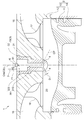
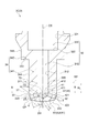
- FIG. 1 is a cross-sectional view schematically showing a sub-chamber type gas engine according to an embodiment of the present invention.
- a sub-chamber gas engine 1 according to some embodiments includes a main chamber forming portion 2 that forms a main combustion chamber 20 (main chamber) of the engine, a main combustion chamber 20 and a plurality of main combustion chambers 20. And a sub-chamber forming portion 3 forming a sub-chamber 30 communicated through the injection hole 4.
- the sub-chamber gas engine 1 has a cylinder block 11 having a cylindrical structure inside, and a cylinder head having a hollow structure capable of covering the top of the cylinder structure. And a piston 14 accommodated in the cylinder 13 and reciprocated, and a sub-chamber nozzle 19 made of, for example, a nickel-based alloy.
- the main combustion chamber 20 described above is defined between the cylinder 13 and the piston 14.
- the sub chamber 30 described above is defined by a sub chamber base 19 mounted on the cylinder head 12 so as to be located at the upper portion (opposite to the piston 14) of the main combustion chamber 20. That is, the main chamber forming portion 2 is formed by the cylinder 13 and the piston 14, and the sub chamber forming portion 3 is formed by the sub chamber cap 19.
- the sub-chamber forming portion 3 has a plurality of injection holes 4 communicating the sub-chamber 30 formed therein with the outside, and via the plurality of injection holes 4.
- the main combustion chamber 20 and the sub chamber 30 communicate with each other.
- the sub-chamber forming portion 3 is a cylindrical small-diameter cylindrical chamber 310 having a predetermined inner diameter, and forms a small-diameter cylindrical chamber 310 to which a plurality of injection holes 4 are connected. It is comprised by the cylinder formation part 31 and the large diameter cylinder formation part 32 which forms the cylindrical large diameter cylinder chamber 320 which has an internal diameter larger than the small diameter cylinder chamber 310.
- the sub chamber 30 includes the small diameter cylindrical chamber 310 and the large diameter cylindrical chamber 320.
- the sub chamber 30 may have another shape such as a cylindrical shape having a constant inner diameter.
- the subchamber central axis CS is the central axis of the small diameter cylindrical chamber 310.
- the main chamber central axis CM and the sub chamber central axis CS coincide with each other, but the sub chamber central axis CS may be inclined with respect to the main chamber central axis CM.
- the central axis of the small diameter cylindrical chamber 310 and the central axis of the large diameter cylindrical chamber 320 do not have to coincide with each other.
- the sub-chamber gas engine 1 includes the igniter 6 provided in the large-diameter cylindrical chamber 320 of the sub-chamber 30 and the fuel for the sub-chamber 30 without the main combustion chamber 20. And a sub-chamber gas supply device 7 for directly supplying gas.
- the ignition device 6 has an ignition unit 61 capable of igniting (igniting) the air-fuel mixture.
- the igniter 6 is an igniter plug, and the igniter 6 is installed in the engine so that the electrode (ignition part 61) of the igniter plug is located on the subchamber center axis CS.
- the ignition device 6 may be installed at a position where the ignition unit 61 is separated from the sub chamber central axis CS by a predetermined distance.
- the sub-chamber gas supply device 7 is configured to supply the sub-chamber fuel gas to the large diameter cylindrical chamber 320 as shown in FIG. The supply of the chamber fuel gas is controlled.
- the sub-chamber gas engine 1 includes an intake port 15 and an exhaust port 16 connected around the cylinder head 12, an intake valve 17 for opening and closing the intake port 15, and an exhaust port 16. And an exhaust valve 18 that opens and closes.
- the intake valve 17 opens and the exhaust valve 18 closes.
- the intake valve 17 is opened, a lean premixed mixture of fuel gas and air is introduced into the cylinder 13 from an intake port 15 connected to the intake valve 17. Further, the subchamber fuel gas is introduced into the subchamber 30 by opening the subchamber fuel gas supply valve 71.
- the sub-chamber fuel gas supply valve 71 is closed.
- the lean premixed air introduced into the cylinder 13 via the intake port 15 is compressed with the rise of the piston 14, a portion of each of the plurality of injection holes 4 of the sub chamber 30 is compressed. Are introduced into the sub-chamber 30.
- the lean premixed gas introduced from the main combustion chamber 20 to the sub-chamber 30 mixes with the sub-chamber fuel gas to generate an air-fuel mixture having a concentration suitable for ignition in the sub-chamber 30.
- the air-fuel mixture in the sub-chamber 30 is ignited by the ignition device 6 at a predetermined timing when the piston 14 is positioned near the compression top dead center, the air-fuel mixture in the sub-chamber 30 is burned, and a combustion flame generated by this combustion
- the fuel is ejected from each of the plurality of injection holes 4 to the cylinder 13 to ignite the lean premixed mixture in the cylinder 13, leading to the combustion of the lean premixed mixture in the main combustion chamber 20.
- the temperature of the inner wall of the sub-chamber forming portion 3 and the injection holes 4 sharply. Since a rapid temperature change occurs in the inner wall of the sub chamber forming portion 3 and the injection hole 4 which is rising, a crack may occur in the inner wall of the sub chamber forming portion 3 and the injection hole 4.
- the inventors of the present invention provide a thin region 5 and a thin region 8 in the sub-chamber forming portion 3 as described later, thereby reducing the heat capacity and rigidity around the injection hole 4 and a plurality of injections at the time of temperature rise. By making the temperature distribution (temperature difference) around the hole gentle, it is possible to reduce the thermal stress generated around the injection hole 4 and to suppress the crack generation around the injection hole 4 Found out.
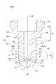
- FIG. 3 is a view for explaining an outer recess formed on the outer peripheral surface of the tip end facing the main combustion chamber.
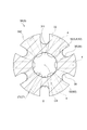
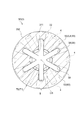
- FIG. 4 is a schematic cross-sectional view taken along line AA shown in FIG.
- FIG. 5 is a view for explaining an example of a thin region provided at the tip end.
- 6 is a schematic cross-sectional view taken along the line BB in FIG.
- FIG. 7 is a view for explaining an inner recessed portion formed on the inner peripheral surface facing the sub chamber at the tip end.
- FIG. 8 is a schematic cross-sectional view taken along line CC in FIG.
- the line AA shown in FIG. 3, the line BB shown in FIG. 5, and the line CC shown in FIG. 7 pass the upper end edge 411 of the sub-chamber side opening 41 of the injection hole 4, and the sub-chamber It extends in a direction orthogonal to the central axis CS.
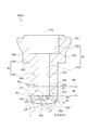
- the sub-chamber central axis CS of the sub-chamber forming portion 3 extends. It includes a cylindrical portion 34 extending along a direction (vertical direction in the drawing) and a tip portion 33 that closes one end (lower end) of the cylindrical portion 34 on the main combustion chamber 20 side.
- the cylindrical portion 34 is a cylindrical large diameter cylindrical portion having a cylindrical small diameter cylindrical portion 341 and an outer diameter larger than the small diameter cylindrical portion 341 as shown in FIGS.
- a stepped surface 343 is formed between the outer peripheral surface 344 of the small diameter cylindrical portion 341 and the outer peripheral surface 345 of the large diameter cylindrical portion 342.
- the sub chamber forming portion 3 abuts the step surface 343 of the cylindrical portion 34 on a portion (not shown) of the cylinder head 12 or contacts the cylinder head 12 via a sealing member or the like (not shown). It is supported by Further, the large diameter cylindrical chamber 320 in the sub-chamber forming portion 3 is formed in a cylindrical shape having a constant inner diameter, and a step between the wall surface 321 of the large diameter cylindrical chamber 320 and the wall surface 312 of the small diameter cylindrical chamber 310 A face 322 is formed.
- the tip end portion 33 is internally formed with a plurality of injection holes 4 in which the center line CP is provided to be inclined with respect to the sub chamber center axis CS. .
- the injection hole diameter of the injection hole 4 is D
- the injection hole length is L.
- the injection hole diameter D and the injection hole length L are determined by the combustion performance of the auxiliary chamber gas engine 1 and the internal pressure of the auxiliary chamber forming portion 3.
- the plurality of injection holes 4 are provided at intervals in the circumferential direction as shown in FIGS. 4, 6 and 8.
- the tip end portion 33 is located on the opposite side of the upper end portion of the small diameter cylindrical portion 341 integrally formed with the large diameter cylindrical portion 342. It is integrally formed at the lower end.
- the distal end portion 33 is formed to project from the lower end portion of the small diameter cylindrical portion 341 and has a convex curved tip end surface 332 as shown in FIGS.
- the tip end portion 33 is formed to be recessed inward from the lower end portion of the small diameter cylindrical portion 341, and may have a concave curved tip end surface.
- the distal end portion 33 may be formed to extend along a direction orthogonal to the extension direction of the sub-chamber central axis CS, and may have a flat distal end surface.
- the tip end portion 33 has a thin region 5 having a thickness T satisfying T ⁇ L. doing.
- the tip portion 33 of the sub chamber forming portion 3 has the thin region 5 in which the thickness T satisfies T ⁇ L. ing. Since the plurality of injection holes 4 are formed inside the distal end portion 33, the thin region 5 is formed around the injection holes 4.
- the heat capacity and rigidity around the plurality of injection holes 4 can be reduced, The temperature distribution (temperature difference) around the plurality of injection holes 4 at the time of temperature rise can be made gentle.
- thermal deformation thermal expansion and thermal contraction
- the heat generated around the plurality of injection holes 4 is generated. It is possible to reduce the thermal stress caused by the strain and the thermal strain being restrained.
- the temperature distribution around the plurality of injection holes 4 gentle at the time of temperature rise, it is possible to suppress non-uniform thermal deformation around the injection holes 4, so thermal strain generated around the plurality of injection holes 4 And the thermal stress which arises by constraining the thermal strain can be reduced.
- the occurrence of a crack around the injection hole 4 due to thermal fatigue can be suppressed.
- the thin-walled area 5 described above is an area including the tip 331 of the tip 33.
- the distal end 331 of the distal end portion 33 is, as shown in FIGS. 2 and 5, an end opposite to the end integrally connected with the cylindrical portion 34 in the extension direction of the subchamber central axis CS. is there.
- the sub-chamber forming portion 3 includes sub-chamber forming portions 3A and 3C having a thin area 5 including the first thin area 51.
- the tip end portion 33 of the sub chamber forming portions 3A and 3C is a tip end more than the lower end edge 422 of the main combustion chamber side opening 42 of the injection hole 4 in the extension direction of the sub chamber central axis CS.
- the thickness gradually decreases toward the tip 331 side.
- the first thin-walled region 51 extends from the tip end 331 to a lower side than the lower edge 412 of the sub-chamber side opening 41 of the injection hole 4 in the extension direction of the sub-chamber central axis CS. It is formed.
- the first thin region 51 does not include the peripheral edge of the injection hole 4, that is, the sub chamber side opening 41 of the injection hole 4 and the main combustion chamber side opening 42.
- the thin-walled region 5 (first thin-walled region 51) is a region including the tip end 331 of the tip end portion 33, compared to the case where the tip end 331 of the tip end portion 33 does not have the thin-walled region 5;
- the thickness of the tip end 331 of the tip end portion 33 can be reduced. Therefore, the heat capacity and rigidity around the injection hole 4 can be reduced, and the temperature distribution around the plurality of injection holes 4 at the time of temperature rise can be made gentle. Crack generation can be suppressed.
- the thin regions 5 are circumferentially adjacent to the tip 33 at the tip 33.
- the sub-chamber forming portion 3 in the plane passing through the upper end edge 411 of the sub-chamber side opening 41 of the injection hole 4 and extending in the direction orthogonal to the sub-chamber central axis CS.
- a part of the thickness T1 in the circumferential direction has the same length as the injection hole length L of the injection hole 4 described above.
- the sub-chamber forming portion 3 includes the sub-chamber forming portion 3 B having the thin area 5 including the second thin area 52.
- the sub-chamber forming portion 3C has a thin region 5 including the second thin region 52, in addition to the first thin region 51 described above.
- the second thin region 52 is formed at the tip end portion 33 between the pair of injection holes 4 adjacent in the circumferential direction of the tip end portion 33.
- the sub-chamber forming portion 3 includes a sub-chamber forming portion 3D having a thin-walled region 5 including the third thin-walled region 53.
- the third thin region 53 is formed at the tip end portion 33 between the pair of injection holes 4 adjacent in the circumferential direction of the tip end portion 33.
- the thin-walled region 5 (the second thin-walled region 52, the third thin-walled region 53) is a region including the tip portion 33 between the pair of injection holes 4 adjacent in the circumferential direction of the tip portion 33. Because of this, it is possible to reduce the thickness between the pair of injection holes 4 adjacent in the circumferential direction. For this reason, the heat capacity and rigidity around the pair of injection holes 4 can be reduced, and the temperature distribution around the pair of injection holes 4 at the time of temperature rise can be made gentle. Cracks around 4 can be suppressed.
- the second thin-walled region 52 described above is formed on the outer peripheral surface (tip end surface 332, outer peripheral surface 333) of the distal end portion 33 facing the main combustion chamber 20, as shown in FIGS.
- At least one outer recess 36, 37 (recess 35).
- the outer recesses 36 and 37 extend at least from the lower end edge 422 of the main combustion chamber side opening 42 to the upper end edge 411 of the auxiliary chamber side opening 41 in the extending direction of the auxiliary chamber central axis CS. It is formed over.
- FIGS. 1 the outer recess 36, 37
- a plurality of outer recesses 36, 37 are formed in the tip 33, the plurality of outer recesses 36, 37 being spaced apart from one another in the circumferential direction of the tip 33, And, it is provided between a pair of injection holes 4 adjacent in the circumferential direction of the tip end portion 33.
- the sub-chamber forming portion 3B is an outer recess 36 on the tip 33 side or the tip 33 of the step surface 343 of the cylindrical portion 34 in the extension direction of the sub-chamber central axis CS.
- the wall thickness of the portion where is not formed is formed to be constant.
- the plurality of outer recesses 36 are formed in a slit shape extending from the tip end surface 332 of the tip end portion 33 to the step surface 343 of the cylindrical portion 34 in the extension direction of the subchamber central axis CS, as shown in FIG. There is.
- the plurality of outer recesses 36 are recessed from the tip end surface 332 of the tip end portion 33 and the outer peripheral surface 344 of the small diameter cylindrical portion 341 so as to have an arc-shaped bottom on the inner side (side facing the sub chamber 30) It is done. For this reason, as shown in FIG. 4, the thickness T of the portion where the outer recess 36 is formed in the circumferential direction of the tip end portion 33 is greater than the thickness T1 of the portion where the outer recess 36 is not formed in the circumferential direction. It is formed small.
- the thickness T1 has the same length as the injection hole length L of the injection hole 4 as described above.
- the sub-chamber forming portion 3C is located on the tip 33 side of the step surface 343 of the cylindrical portion 34 in the extending direction of the sub-chamber central axis CS and the main of the injection hole 4
- the thickness of a portion where the outer recess 37 is not formed on the side of the cylindrical portion 34 of the tip end portion 33 including the lower end edge 422 of the combustion chamber side opening 42 is formed to be constant.
- the plurality of outer recesses 37 are formed in a slit shape extending from the tip end surface 332 of the tip end 33 to the lower end of the small diameter cylindrical portion 341 in the extension direction of the subchamber central axis CS, as shown in FIG. There is.
- the plurality of outer recesses 37 are arc-shaped inward (to face the sub chamber 30) from the outer peripheral surface 333 of the distal end portion 33 and the outer peripheral surface 344 of the small diameter cylindrical portion 341 so as to have a constant depth. It is concavely formed to have a bottom surface. For this reason, as shown in FIG. 6, the thickness T of the portion where the outer recess 37 is formed in the circumferential direction of the tip end portion 33 is greater than the thickness T1 of the portion where the outer recess 37 is not formed in the circumferential direction. It is formed small.
- the thickness T1 has the same length as the injection hole length L of the injection hole 4 as described above.
- the thin-walled region 5 (the second thin-walled region 52) is at least one outer recess formed on the outer peripheral surface (the end surface 332, the outer peripheral surface 333) of the tip 33 facing the main combustion chamber 20. 36 and 37 are included. That is, since the thin-walled region 5 is defined by the at least one outer recess 36, 37 formed on the outer peripheral surface of the tip 33, thermal strain generated around the main combustion chamber side opening 42 of the plurality of injection holes 4 and It is possible to reduce the thermal stress caused by the thermal strain being constrained. In addition, it is easy to form the outer side recessed parts 36 and 37 in the outer peripheral surface of the tip part 33 by cutting etc., for example.
- the third thin region 53 described above is formed on the inner circumferential surface (bottom surface 311, wall surface 312) of the distal end portion 33 facing the sub-chamber 30, as shown in FIGS. It is configured to include at least one inner recess 38 (recess 35). As shown in FIG. 7, the inner recess 38 is formed at least from the lower end edge 422 of the main combustion chamber side opening 42 to the upper end edge 411 of the auxiliary chamber side opening 41 in the extension direction of the auxiliary chamber central axis CS. There is. In the embodiment shown in FIG.
- a plurality of inner recesses 38 are formed in the tip 33, and the plurality of inner recesses 38 are spaced apart from one another in the circumferential direction of the tip 33 and It is provided between a pair of injection holes 4 adjacent in the circumferential direction.
- the sub-chamber forming portion 3D is an inner recess 38 on the tip 33 side or the tip 33 of the step surface 343 of the cylindrical portion 34 in the extension direction of the sub-chamber central axis CS.
- the wall thickness of the portion where is not formed is formed to be constant.
- the plurality of inner recesses 38 are formed in a slit shape extending from the bottom surface 311 of the small diameter cylindrical chamber 310 to the step surface 322 of the large diameter cylindrical chamber 320 in the extending direction of the subchamber central axis CS, as shown in FIG. ing.
- the plurality of inner recesses 38 are recessed from the bottom surface 311 and the wall surface 312 of the small diameter cylindrical chamber 310 so as to have a circular arc bottom surface on the inner side (side facing the main combustion chamber 20) so as to be a fixed depth. It is done.
- the plurality of inner recesses 38 are connected to each other at the bottom surface 311 of the small diameter cylindrical chamber 310, as shown in FIG. For this reason, as shown in FIG. 8, the thickness T of the portion where the inner recess 38 is formed in the circumferential direction of the tip end portion 33 is greater than the thickness T1 of the portion where the inner recess 38 is not formed in the circumferential direction. It is formed small.
- the thickness T1 has the same length as the injection hole length L of the injection hole 4 as described above.
- the thin-walled region 5 (third thin-walled region 53) includes at least one inner recess 38 formed on the inner peripheral surface (bottom surface 311, wall surface 312) facing the sub-chamber 30 of the tip end portion 33. It consists of That is, since the thin-walled region 5 is defined by the at least one inner recess 38 formed in the inner peripheral surface of the tip portion 33, the thermal strain and heat generated around the sub chamber side opening 41 of the plurality of injection holes 4 It is possible to reduce the thermal stress caused by the restraint of strain.
- the inner recess 38 is formed up to the step surface 343 of the cylindrical portion 34 in the extension direction of the subchamber central axis CS, the inner recess 38 is formed inside the tip 33 by cutting, for example. It is easy to do.
- the recesses 35 (outer recesses 36, 37, inner recess 38) described above are tipped along the extension direction of the subchamber central axis CS. It extends from the portion 33 over at least a portion of the tubular portion 34 beyond the reference plane RP described above.
- the recess 35 extends from the tip 33 to at least a part of the cylindrical portion 34 along the extension direction of the subchamber central axis CS, so the tip 33 side of the cylindrical 34
- the wall thickness is formed thin at least in part.
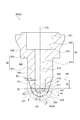
- FIG. 9 is a schematic cross-sectional view showing an enlarged vicinity of a tip end portion of the sub chamber forming portion in another embodiment, and is for explaining a chamfered shape formed on the periphery of the sub chamber side opening of the injection hole.
- the sub-chamber forming portion 3 includes a sub-chamber forming portion 3E having a chamfered portion 414 in the sub-chamber side opening 41 described above.
- the sub-chamber forming portion 3E has the same configuration as the sub-chamber forming portion 3C except that a chamfered portion 414 having a C-chamfered shape is provided all around the periphery of the sub-chamber side opening 41. There is.
- the chamfer 414 in the sub chamber side opening 41 of sub chamber formation part 3A, 3B, 3D and 3 G mentioned later.
- the chamfered portion may be formed over the entire circumference of the main combustion chamber side opening 42.
- the sub-chamber forming portion 3E has the chamfered portion 414 in the sub-chamber side opening 41, and thus constitutes the sub-chamber side opening 41 as compared with the case where the chamfered portion 414 is not provided. Since the temperature of the portion can be reduced, it is possible to reduce the thermal strain generated around the sub-chamber side openings 41 of the plurality of injection holes 4 and the thermal stress generated by the thermal strain being restrained.
- the stress analysis was performed based on the temperature analysis and the temperature analysis results for the sub-chamber forming unit 3 in the sub-chamber type gas engine 1 according to some embodiments described above. The details will be described below.
- the temperature change of the sub-chamber forming part 3 was estimated by applying the thermal conditions such as the change of the ambient temperature and the heat transfer coefficient at the time of engine operation according to each surface such as the bottom surface 311 and the wall surface 312. .
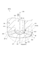
- FIG. 10 is a view for explaining temperature analysis results and stress analysis results around the injection hole of the sub chamber formation portion.
- the sub chamber side opening 41 of the injection hole 4 shown in FIG. 10 has a rapid temperature change as compared with the other portion of the sub chamber forming portion 3 and the sub chamber forming portion 3 It becomes hotter than other parts.
- stress analysis was performed to estimate a strain change, and a strain range at each of the measurement points P1 to P3 was calculated.
- the measurement point P1 is located on the upper end edge 411 of the sub chamber side opening 41
- the measurement point P3 is located on the lower end edge 412 of the sub chamber side opening 41.
- the measurement point P2 is located on the middle edge 413 located between the upper end edge 411 and the lower end edge 412 of the sub-chamber side opening 41 in the extension direction of the sub-chamber central axis CS.
- the sub-chamber side opening 41 as described above has the chamfered portion 414, as shown in FIG. 9, the upper end edge 411, the lower end edge 412 and the middle edge of the chamfered portion 414 on the periphery of the main combustion chamber 20 side. 413 are provided.
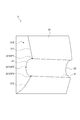
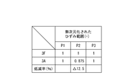
- FIG. 11 is a chart showing a non-dimensionalized strain range in the sub-chamber side opening of the sub-chamber forming part having the first thin-walled region, for comparison with the sub-chamber forming part having no thin-walled region. is there.
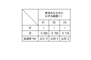
- FIG. 12 is a chart showing a non-dimensionalized strain range in the sub-chamber side opening of the sub-chamber forming portion having a chamfered shape formed on the periphery of the first thin region, the second thin region and the sub-chamber side opening It is a chart for comparing with the subchamber formation part which does not have a thin region.
- 3F in FIGS. 11 and 12 is a sub-chamber forming portion having a tip as shown by a two-dot chain line in FIG. 2 and having no thin region 5.
- the strain range at each measurement point P1 to P3 of the sub chamber forming portion 3F and the sub chamber forming portion 3A is non-dimensionalized and represented at a ratio of 1 to the sub chamber forming portion 3F, and The reduction rate of the chamber forming portion 3A with respect to the sub chamber forming portion 3F is shown.
- the sub-chamber forming portion 3A has the first thin region 51, whereby the strain range at the measurement point P2 is reduced as compared to the sub-chamber forming portion 3F. Therefore, the sub-chamber forming portion 3A can suppress the occurrence of a crack generated between the pair of injection holes 4 adjacent to each other in the circumferential direction, as compared to the sub-chamber forming portion 3F.
- the strain range at each measurement point P1 to P3 of the sub-chamber forming portion 3F and the sub-chamber forming portion 3E is non-dimensionalized and represented at a ratio of 1 to the sub-chamber forming portion 3F.
- a reduction rate of the chamber forming portion 3E with respect to the sub chamber forming portion 3F is shown.
- the sub-chamber forming portion 3E includes the first thin region 51, the second thin region 52, and the chamfered portion 414 of the sub-chamber side opening 41, so that the sub-chamber forming portion 3E can be compared to the sub-chamber forming portion 3F.
- the strain range at all the measurement points P1 to P3 is reduced.
- the sub-chamber forming portion 3E has a larger reduction rate to the sub-chamber forming portion 3F than the sub-chamber forming portion 3A shown in FIG. Therefore, the sub-chamber forming portion 3E can reduce the thermal stress generated around the plurality of injection holes 4 and can suppress the occurrence of the crack, as compared with the sub-chamber forming portions 3A and 3F.
- the tip end portion 33 has the thin-walled region 5 which is a region where the thickness T satisfies T ⁇ L, but in some embodiments described later, the tip end portion 33 is It has a thin region 8 in which the thickness T satisfies T ⁇ T0. The details will be described below.
- the sub chamber forming portion 3 in the sub chamber type gas engine 1 has the sub chamber central axis CS of the sub chamber forming portion 3 extended. It includes the above-described cylindrical portion 34 extending along the existing direction (vertical direction in the figure), and the above-described tip portion 33 closing the one end portion (lower end portion) of the cylindrical portion 34 on the main combustion chamber 20 side. It is.
- FIG. 13 is a schematic cross-sectional view of the sub chamber forming portion in another embodiment.
- the main combustion chamber 20 side ( A surface passing through a position 346 separated by a reference length RL in the direction opposite to the lower side in the drawing) and extending in a direction orthogonal to the subchamber central axis CS is taken as a reference surface RP.
- the reference length RL is three times (predetermined times) the injection hole diameter D of the injection hole 4.
- the tip 33 is located closer to the main combustion chamber 20 than the reference plane RP, as shown in FIGS. 2, 3, 5, 7 and 13.
- the reference surface RP is apart from the injection hole 4 and the influence of the heat produced by the above-described combustion flame is small.
- the tip 33 located closer to the main combustion chamber 20 than the reference surface RP is largely affected by the heat produced by the above-described combustion flame. For this reason, the distal end portion 33 is more effective than the cylindrical portion 34 by providing the thin region 8.
- the tip portion 33 has a thickness T of T ⁇ T0. It has a thin area 8 which is an area to be filled.
- a surface of the sub chamber forming portion 3 which passes through the upper end edge 411 of the sub chamber side opening 41 of the injection hole 4 and extends in a direction orthogonal to the sub chamber central axis CS Between the reference plane RP and the reference plane RP, the sectional shape along the direction orthogonal to the subchamber central axis CS is formed in the same cylindrical shape.
- the tip portion 33 passes the upper end edge 411 of the sub chamber side opening 41 of the injection hole 4, and a part of the circumferential direction in the cross section extending in the direction orthogonal to the sub chamber central axis CS It has the same thickness T1 as the thickness T0 in the plane RP.
- the thickness T1 has the same length as the injection hole length L of the injection hole 4 described above.
- the thickness in the circumferential direction is not constant, but in this case, the maximum thickness in the circumferential direction is the thickness T0 or the thickness T1 described above.
- the thin area 8 includes a first thin area 81 which is the same as the first thin area 51 of the thin area 5 described above.
- the thin area 8 includes a second thin area 82 which is the same as the second thin area 52 of the thin area 5 described above. Therefore, the second thin-walled region 82 is a region including the space between the pair of injection holes 4 adjacent in the circumferential direction of the distal end portion 33 at the distal end portion 33. Further, the second thin-walled region 82 is configured to include at least one outer concave portion 36, 37 formed on the outer peripheral surface (the front end surface 332, the outer peripheral surface 333) of the front end portion 33 facing the main combustion chamber 20. .
- the thin area 8 includes a third thin area 83 which is the same as the third thin area 53 of the thin area 5 described above.
- the third thin-walled region 83 is a region in the tip end portion 33 that includes between the pair of injection holes 4 adjacent in the circumferential direction of the tip end portion 33.
- the third thin region 83 is configured to include at least one inner recess 38 (recess 35) formed on the inner peripheral surface (bottom surface 311, wall surface 312) of the distal end portion 33 facing the sub chamber 30. .
- the sub-chamber forming portion 3 includes a sub-chamber forming portion 3G having a thin area 8 including the fourth thin area 84.
- the tip end portion 33 of the sub chamber forming portion 3G is closer to the cylindrical portion 34 than the upper end edge 421 of the main combustion chamber side opening 42 of the injection hole 4 in the extension direction of the sub chamber central axis CS.
- the thickness gradually decreases toward the tip end 331, and the thickness is constant on the tip end 331 side of the upper end edge 421, and the thickness is equal to the injection hole length L1.
- the thickness T of the distal end portion 33 is formed smaller than the thickness T0 in the reference plane RP.
- the fourth thin-walled region 84 is formed from the tip end 331 to a position above the upper end edge 421 of the main combustion chamber side opening 42 of the injection hole 4 in the extension direction of the subchamber central axis CS. There is.
- the tip end portion 33 of the sub chamber forming portion 3 extends along the direction in which the sub chamber central axis CS extends from the upper end edge 411 of the sub chamber side opening 41 of the injection hole 4. It passes through a reference length RL in a direction opposite to the side, that is, a position 346 separated by a length three times (predetermined multiple) of the injection hole diameter D of the injection hole 4 and orthogonal to the subchamber central axis CS. It is located closer to the main combustion chamber 20 than the reference plane RP extending in the direction.
- the tip portion 33 has a thin region 8 in which the thickness T satisfies T ⁇ T0, where T0 is the thickness of the sub-chamber forming portion 3 on the reference surface RP.
- the thin-walled region 8 has a thickness T smaller than that of the reference surface RP where the influence of the heat produced by the combustion flame is small.
- the thin-walled area 8 (first thin-walled area 81, fourth thin-walled area 84) described above is an area including the tip 331 described above.
- the thin-walled area 8 (first thin-walled area 81, fourth thin-walled area 84) is an area including the tip end 331 of the tip end portion 33, the tip end 331 of the tip end portion 33 has the thin-walled area 8
- the thickness of the tip end 331 of the tip end portion 33 can be reduced as compared with the case of not performing. Therefore, the heat capacity and rigidity around the injection hole 4 can be reduced, and the temperature distribution around the plurality of injection holes 4 at the time of temperature rise can be made gentle. Crack generation can be suppressed. It is easy to form the thin region 8 including the tip 331 of the tip 33 by cutting, for example, with respect to the sub-chamber forming part 3 which does not have the thin region 8 at the tip 331 of the tip 33.
- the thin-walled area 8 (fourth thin-walled area 84) mentioned above is at least a part of the periphery of the main combustion chamber side opening 42 of the injection hole 4 at the tip 33.
- the peripheral edge of the main combustion chamber side opening 42 includes an upper end edge 421 and a lower end edge 422 as shown in FIG. 13.
- the fourth thin region 84 includes both the upper end edge 421 and the lower end edge 422 of the main combustion chamber side opening 42 of the injection hole 4.
- the thin-walled region 8 (fourth thin-walled region 84) is a region including at least a part of the peripheral edge of the main combustion chamber side opening 42 of the injection hole 4 at the tip end portion 33.
- the wall thickness around can be reduced. Therefore, the heat capacity and rigidity around the injection hole 4 can be reduced, and the temperature distribution around the plurality of injection holes 4 at the time of temperature rise can be made gentle. Crack generation can be suppressed.
- the reference length RL which is the length between the top edge 411 and the position 346 described above, The length is 3 times (predetermined times) the injection hole diameter D of the hole 4, but the reference length RL may be longer or shorter than 3 times the injection hole diameter D, for example, the injection of the injection hole 4 It may be one or twice as long as the pore diameter D. Also, the reference length RL may be zero. Further, when the reference length RL is short or zero, the reference plane RP may be provided at a position corresponding to the reference length RL. When the reference length RL is shortened, the range of the tip end 33 is narrowed, and accordingly, the thin region 8 is also formed around the injection hole 4. For this reason, compared with the case where the reference length RL is increased, it is possible to reduce the thermal strain generated around the plurality of injection holes 4 and the thermal stress generated by the thermal strain being restrained.
- the thin-walled region 5 is a region in which the thickness T satisfies T ⁇ T0
- the thin-walled region 8 is a region in which the thickness T satisfies T ⁇ L.
- the thickness T of the thin region 5 and the thin region 8 has the minimum thickness that can withstand the internal pressure applied to the sub-chamber forming portion 3 .
- the thickness T is small, the strength decreases as compared with the case where the thickness T is large, but the heat capacity and rigidity around the plurality of injection holes 4 can be reduced, and the heat generated around the plurality of injection holes 4 Stress can be reduced.
- the thin region 5 and the thin region 8 are in the above-described range, the sub-chamber forming portion 3 can effectively suppress the crack generation while maintaining the necessary strength.
- the thin region 5 and the thin region 8 do not include the peripheries of the sub chamber side opening 41 and the main combustion chamber side opening 42 of the injection hole 4. In this case, since the injection hole diameter D of the injection hole 4 and the injection hole length L are maintained, the performance of the combustion flame ejected from the injection hole 4 can be maintained.
- the recess 35 is formed along the extension direction of the sub chamber central axis CS, but may be formed along another direction.
- the recess may be formed along the circumferential direction of the distal end portion 33 or the cylindrical portion 34.
- the present invention is not limited to the above-described embodiments, and includes the embodiments in which the above-described embodiments are modified, and the embodiments in which these embodiments are appropriately combined.
Landscapes
- Engineering & Computer Science (AREA)
- Chemical & Material Sciences (AREA)
- Combustion & Propulsion (AREA)
- Mechanical Engineering (AREA)
- General Engineering & Computer Science (AREA)
- Combustion Methods Of Internal-Combustion Engines (AREA)
Priority Applications (2)
| Application Number | Priority Date | Filing Date | Title |
|---|---|---|---|
| US16/649,864 US11300039B2 (en) | 2017-09-29 | 2018-08-28 | Precombustion chamber gas engine |
| EP18861842.5A EP3667041B1 (en) | 2017-09-29 | 2018-08-28 | Auxiliary chamber type gas engine |
Applications Claiming Priority (2)
| Application Number | Priority Date | Filing Date | Title |
|---|---|---|---|
| JP2017190263A JP7002272B2 (ja) | 2017-09-29 | 2017-09-29 | 副室式ガスエンジン |
| JP2017-190263 | 2017-09-29 |
Publications (1)
| Publication Number | Publication Date |
|---|---|
| WO2019065053A1 true WO2019065053A1 (ja) | 2019-04-04 |
Family
ID=65901338
Family Applications (1)
| Application Number | Title | Priority Date | Filing Date |
|---|---|---|---|
| PCT/JP2018/031833 Ceased WO2019065053A1 (ja) | 2017-09-29 | 2018-08-28 | 副室式ガスエンジン |
Country Status (4)
| Country | Link |
|---|---|
| US (1) | US11300039B2 (enExample) |
| EP (1) | EP3667041B1 (enExample) |
| JP (1) | JP7002272B2 (enExample) |
| WO (1) | WO2019065053A1 (enExample) |
Cited By (2)
| Publication number | Priority date | Publication date | Assignee | Title |
|---|---|---|---|---|
| US10777976B1 (en) * | 2019-05-07 | 2020-09-15 | Ngk Spark Plug Co., Ltd. | Spark plug |
| GB2574201B (en) * | 2018-05-28 | 2021-10-27 | Caterpillar Energy Solutions Gmbh | Pre-chamber body for an internal combustion engine |
Citations (9)
| Publication number | Priority date | Publication date | Assignee | Title |
|---|---|---|---|---|
| JPS5949720U (ja) * | 1982-09-25 | 1984-04-02 | トヨタ自動車株式会社 | デイ−ゼルエンジンの予燃焼室構造 |
| JPH05504185A (ja) * | 1990-02-06 | 1993-07-01 | キャタピラー インコーポレイテッド | 内燃機関及びその方法並びにそれらに用いるノズル部材 |
| JPH07127529A (ja) * | 1993-10-29 | 1995-05-16 | Isuzu Motors Ltd | 2層副室を有する遮熱型ガスエンジン |
| JP2003254195A (ja) * | 2002-03-04 | 2003-09-10 | Mitsubishi Heavy Ind Ltd | 燃料噴射弁取付構造及び冷却構造 |
| US20030213461A1 (en) * | 2002-03-02 | 2003-11-20 | Regueiro Jose Francisco | Prechamber combustion system |
| WO2011080917A1 (ja) * | 2009-12-28 | 2011-07-07 | 川崎重工業株式会社 | 副室式ガスエンジン |
| JP5357926B2 (ja) | 2010-12-27 | 2013-12-04 | 川崎重工業株式会社 | 副室式ガスエンジン |
| JP2014066245A (ja) * | 2012-09-26 | 2014-04-17 | Ge Jenbacher Gmbh & Co Ohg | 内燃機関の予燃室システム |
| US20160326946A1 (en) * | 2015-05-04 | 2016-11-10 | Caterpillar Inc. | Fuel Combustion System, Nozzle for Prechamber Assembly with Curved Orifices, and Method of Making Same |
Family Cites Families (7)
| Publication number | Priority date | Publication date | Assignee | Title |
|---|---|---|---|---|
| JPH09256850A (ja) * | 1996-03-25 | 1997-09-30 | Isuzu Ceramics Kenkyusho:Kk | 副室式ガスエンジン |
| JP2007113536A (ja) | 2005-10-24 | 2007-05-10 | Nissan Motor Co Ltd | 副室式内燃機関 |
| US9225151B2 (en) * | 2012-02-09 | 2015-12-29 | Cummins Ip, Inc. | Spark plug for removing residual exhaust gas and associated combustion chamber |
| EP2700796B1 (en) * | 2012-08-22 | 2016-08-10 | Caterpillar Motoren GmbH & Co. KG | Pre-combustion chamber of an internal combustion engine and method of operating the same |
| US10024220B2 (en) * | 2013-03-12 | 2018-07-17 | Prometheus Applied Technologies, Llc | Active scavenge prechamber |
| AT514813B1 (de) * | 2013-09-25 | 2015-04-15 | Ge Jenbacher Gmbh & Co Og | Anordnung aus einem Zylinderkopf und einem Vorkammersystem |
| GB2574201B (en) | 2018-05-28 | 2021-10-27 | Caterpillar Energy Solutions Gmbh | Pre-chamber body for an internal combustion engine |
-
2017
- 2017-09-29 JP JP2017190263A patent/JP7002272B2/ja active Active
-
2018
- 2018-08-28 EP EP18861842.5A patent/EP3667041B1/en active Active
- 2018-08-28 WO PCT/JP2018/031833 patent/WO2019065053A1/ja not_active Ceased
- 2018-08-28 US US16/649,864 patent/US11300039B2/en active Active
Patent Citations (9)
| Publication number | Priority date | Publication date | Assignee | Title |
|---|---|---|---|---|
| JPS5949720U (ja) * | 1982-09-25 | 1984-04-02 | トヨタ自動車株式会社 | デイ−ゼルエンジンの予燃焼室構造 |
| JPH05504185A (ja) * | 1990-02-06 | 1993-07-01 | キャタピラー インコーポレイテッド | 内燃機関及びその方法並びにそれらに用いるノズル部材 |
| JPH07127529A (ja) * | 1993-10-29 | 1995-05-16 | Isuzu Motors Ltd | 2層副室を有する遮熱型ガスエンジン |
| US20030213461A1 (en) * | 2002-03-02 | 2003-11-20 | Regueiro Jose Francisco | Prechamber combustion system |
| JP2003254195A (ja) * | 2002-03-04 | 2003-09-10 | Mitsubishi Heavy Ind Ltd | 燃料噴射弁取付構造及び冷却構造 |
| WO2011080917A1 (ja) * | 2009-12-28 | 2011-07-07 | 川崎重工業株式会社 | 副室式ガスエンジン |
| JP5357926B2 (ja) | 2010-12-27 | 2013-12-04 | 川崎重工業株式会社 | 副室式ガスエンジン |
| JP2014066245A (ja) * | 2012-09-26 | 2014-04-17 | Ge Jenbacher Gmbh & Co Ohg | 内燃機関の予燃室システム |
| US20160326946A1 (en) * | 2015-05-04 | 2016-11-10 | Caterpillar Inc. | Fuel Combustion System, Nozzle for Prechamber Assembly with Curved Orifices, and Method of Making Same |
Non-Patent Citations (1)
| Title |
|---|
| See also references of EP3667041A4 |
Cited By (3)
| Publication number | Priority date | Publication date | Assignee | Title |
|---|---|---|---|---|
| GB2574201B (en) * | 2018-05-28 | 2021-10-27 | Caterpillar Energy Solutions Gmbh | Pre-chamber body for an internal combustion engine |
| US11530639B2 (en) | 2018-05-28 | 2022-12-20 | Caterpillar Energy Solutions Gmbh | Pre-chamber body for an internal combustion engine |
| US10777976B1 (en) * | 2019-05-07 | 2020-09-15 | Ngk Spark Plug Co., Ltd. | Spark plug |
Also Published As
| Publication number | Publication date |
|---|---|
| US11300039B2 (en) | 2022-04-12 |
| JP7002272B2 (ja) | 2022-02-04 |
| EP3667041A4 (en) | 2020-07-22 |
| EP3667041B1 (en) | 2021-10-13 |
| US20210363914A1 (en) | 2021-11-25 |
| JP2019065742A (ja) | 2019-04-25 |
| EP3667041A1 (en) | 2020-06-17 |
Similar Documents
| Publication | Publication Date | Title |
|---|---|---|
| US3980057A (en) | Torch ignition type internal combustion engine | |
| JP6038339B2 (ja) | 副室式ガスエンジン用のピストンおよび副室式ガスエンジン | |
| WO2014046185A1 (ja) | 副室式ガスエンジン | |
| JP7159810B2 (ja) | 副室付内燃機関 | |
| CN111219241B (zh) | 带副室内燃机 | |
| CN111206983B (zh) | 带副室内燃机 | |
| JP6020856B2 (ja) | エンジンの燃焼室構造 | |
| WO2019065053A1 (ja) | 副室式ガスエンジン | |
| WO2018110326A1 (ja) | 副室式ガスエンジン | |
| JP6919558B2 (ja) | 内燃機関 | |
| JP2007154827A (ja) | 内燃機関の燃焼制御装置 | |
| WO2021176949A1 (ja) | 内燃機関用のスパークプラグ | |
| JP5085419B2 (ja) | エンジン及びエンジン用点火プラグ | |
| JP7260331B2 (ja) | 副燃焼室付き内燃機関 | |
| JP6795985B2 (ja) | 副室式ガスエンジン | |
| JP6654917B2 (ja) | ピストン | |
| JP7272820B2 (ja) | 副燃焼室付き内燃機関 | |
| JP2015021391A (ja) | 内燃機関 | |
| US20230097104A1 (en) | Pre-Chamber Spark Plug for a Combustion Chamber of an Internal Combustion Engine, Internal Combustion Engine and Motor Vehicle | |
| JP4185847B2 (ja) | 内燃機関の点火プラグ装置 | |
| JP2015222055A (ja) | 火花点火式内燃機関 | |
| JP2021173172A (ja) | エンジン | |
| JP2021012794A (ja) | 内燃機関用のスパークプラグ及びこれを備えた内燃機関 | |
| WO2019130801A1 (ja) | ガスエンジンの燃焼室構造 | |
| JP2013053586A (ja) | エンジン |
Legal Events
| Date | Code | Title | Description |
|---|---|---|---|
| 121 | Ep: the epo has been informed by wipo that ep was designated in this application |
Ref document number: 18861842 Country of ref document: EP Kind code of ref document: A1 |
|
| ENP | Entry into the national phase |
Ref document number: 2018861842 Country of ref document: EP Effective date: 20200309 |
|
| NENP | Non-entry into the national phase |
Ref country code: DE |