WO2019065053A1 - Auxiliary chamber type gas engine - Google Patents
Auxiliary chamber type gas engine Download PDFInfo
- Publication number
- WO2019065053A1 WO2019065053A1 PCT/JP2018/031833 JP2018031833W WO2019065053A1 WO 2019065053 A1 WO2019065053 A1 WO 2019065053A1 JP 2018031833 W JP2018031833 W JP 2018031833W WO 2019065053 A1 WO2019065053 A1 WO 2019065053A1
- Authority
- WO
- WIPO (PCT)
- Prior art keywords
- chamber
- sub
- tip
- thin
- injection hole
- Prior art date
Links
Images


Classifications
-
- F—MECHANICAL ENGINEERING; LIGHTING; HEATING; WEAPONS; BLASTING
- F02—COMBUSTION ENGINES; HOT-GAS OR COMBUSTION-PRODUCT ENGINE PLANTS
- F02B—INTERNAL-COMBUSTION PISTON ENGINES; COMBUSTION ENGINES IN GENERAL
- F02B19/00—Engines characterised by precombustion chambers
- F02B19/16—Chamber shapes or constructions not specific to sub-groups F02B19/02 - F02B19/10
- F02B19/18—Transfer passages between chamber and cylinder
-
- F—MECHANICAL ENGINEERING; LIGHTING; HEATING; WEAPONS; BLASTING
- F02—COMBUSTION ENGINES; HOT-GAS OR COMBUSTION-PRODUCT ENGINE PLANTS
- F02B—INTERNAL-COMBUSTION PISTON ENGINES; COMBUSTION ENGINES IN GENERAL
- F02B19/00—Engines characterised by precombustion chambers
- F02B19/10—Engines characterised by precombustion chambers with fuel introduced partly into pre-combustion chamber, and partly into cylinder
- F02B19/1004—Engines characterised by precombustion chambers with fuel introduced partly into pre-combustion chamber, and partly into cylinder details of combustion chamber, e.g. mounting arrangements
- F02B19/1014—Engines characterised by precombustion chambers with fuel introduced partly into pre-combustion chamber, and partly into cylinder details of combustion chamber, e.g. mounting arrangements design parameters, e.g. volume, torch passage cross sectional area, length, orientation, or the like
-
- F—MECHANICAL ENGINEERING; LIGHTING; HEATING; WEAPONS; BLASTING
- F02—COMBUSTION ENGINES; HOT-GAS OR COMBUSTION-PRODUCT ENGINE PLANTS
- F02B—INTERNAL-COMBUSTION PISTON ENGINES; COMBUSTION ENGINES IN GENERAL
- F02B19/00—Engines characterised by precombustion chambers
- F02B19/16—Chamber shapes or constructions not specific to sub-groups F02B19/02 - F02B19/10
-
- F—MECHANICAL ENGINEERING; LIGHTING; HEATING; WEAPONS; BLASTING
- F02—COMBUSTION ENGINES; HOT-GAS OR COMBUSTION-PRODUCT ENGINE PLANTS
- F02B—INTERNAL-COMBUSTION PISTON ENGINES; COMBUSTION ENGINES IN GENERAL
- F02B19/00—Engines characterised by precombustion chambers
- F02B19/12—Engines characterised by precombustion chambers with positive ignition
-
- F—MECHANICAL ENGINEERING; LIGHTING; HEATING; WEAPONS; BLASTING
- F02—COMBUSTION ENGINES; HOT-GAS OR COMBUSTION-PRODUCT ENGINE PLANTS
- F02B—INTERNAL-COMBUSTION PISTON ENGINES; COMBUSTION ENGINES IN GENERAL
- F02B43/00—Engines characterised by operating on gaseous fuels; Plants including such engines
-
- F—MECHANICAL ENGINEERING; LIGHTING; HEATING; WEAPONS; BLASTING
- F02—COMBUSTION ENGINES; HOT-GAS OR COMBUSTION-PRODUCT ENGINE PLANTS
- F02M—SUPPLYING COMBUSTION ENGINES IN GENERAL WITH COMBUSTIBLE MIXTURES OR CONSTITUENTS THEREOF
- F02M21/00—Apparatus for supplying engines with non-liquid fuels, e.g. gaseous fuels stored in liquid form
- F02M21/02—Apparatus for supplying engines with non-liquid fuels, e.g. gaseous fuels stored in liquid form for gaseous fuels
- F02M21/0218—Details on the gaseous fuel supply system, e.g. tanks, valves, pipes, pumps, rails, injectors or mixers
- F02M21/0248—Injectors
- F02M21/0281—Adapters, sockets or the like to mount injection valves onto engines; Fuel guiding passages between injectors and the air intake system or the combustion chamber
-
- Y—GENERAL TAGGING OF NEW TECHNOLOGICAL DEVELOPMENTS; GENERAL TAGGING OF CROSS-SECTIONAL TECHNOLOGIES SPANNING OVER SEVERAL SECTIONS OF THE IPC; TECHNICAL SUBJECTS COVERED BY FORMER USPC CROSS-REFERENCE ART COLLECTIONS [XRACs] AND DIGESTS
- Y02—TECHNOLOGIES OR APPLICATIONS FOR MITIGATION OR ADAPTATION AGAINST CLIMATE CHANGE
- Y02T—CLIMATE CHANGE MITIGATION TECHNOLOGIES RELATED TO TRANSPORTATION
- Y02T10/00—Road transport of goods or passengers
- Y02T10/10—Internal combustion engine [ICE] based vehicles
- Y02T10/12—Improving ICE efficiencies
Definitions
- the present disclosure relates to a sub-chamber gas engine that burns an air-fuel mixture in a main combustion chamber by causing a combustion flame generated in the sub-chamber to be ejected to the main combustion chamber through a plurality of injection holes.
- a sub combustion chamber (main chamber) defined between a piston and a cylinder head, and a sub combustion chamber (sub chamber) communicated with the main combustion chamber via a plurality of injection holes.
- a room-type gas engine is known (for example, patent document 1).
- the sub-chamber gas engine ignites the air-fuel mixture in the sub-chamber by an ignition device such as a spark plug, and the combustion flame generated by the ignition is ejected from each of a plurality of injection holes provided at the tip of the sub-chamber. , Burn the lean premixed mixture in the main combustion chamber.
- Patent Document 1 when the temperature of the inner wall of the sub chamber rises (increases temperature) to about 1000 ° C., the inner wall expands, the expanded inner wall shrinks due to the temperature decrease, and the inner wall of the sub chamber expands. It is disclosed that there is a risk of thermal fatigue due to repetition of shrinkage and contraction, and cracking on the inner wall. Further, Patent Document 1 also discloses that a large number of cracks are generated in the vicinity of the auxiliary chamber side opening edge of the injection hole.
- Patent Document 1 it is known that the cause of the crack generation in the vicinity of the opening edge of the sub chamber side is that the temperature of the opening edge of the sub chamber side becomes extremely high compared to the surrounding portion. Accordingly, in order to reduce the temperature difference between the opening edge and the surrounding area, it is disclosed to form the subchamber side opening edge of the injection hole into a curved surface having a constant radius of curvature.
- Patent Document 1 Although the occurrence of a crack at the subchamber side opening edge can be suppressed as compared with the case where the above curved surface is not formed at the subchamber side opening edge, the effect caused by forming the curved surface Is limited, and if it is desired to further suppress the occurrence of cracks, further measures are required.
- a sub-chamber gas engine according to at least one embodiment of the present invention, A main chamber forming part forming a main combustion chamber, A sub-chamber gas engine comprising: a sub-chamber forming portion forming a sub-chamber communicated with the main combustion chamber through a plurality of injection holes, The sub-chamber forming portion closes a cylindrical portion extending along a direction in which the sub-chamber central axis of the sub-chamber forming portion extends, and closes one end portion on the main combustion chamber side of the cylindrical portion. And a tip where the injection hole is formed, The tip portion has a thin-walled region which is a region where the thickness T satisfies T ⁇ L when the length dimension of the injection hole is L.
- the tip end portion of the sub chamber formation portion has a thin region which is a region in which the thickness T satisfies T ⁇ L.
- the thin-walled region is formed around the injection holes.
- Such a thin-walled region is formed around the injection holes at the tip end portion where the influence of heat caused by the combustion flame is large, thereby reducing the heat capacity and rigidity around the plurality of injection holes, and at the time of temperature rise.
- the temperature distribution (temperature difference) around the plurality of injection holes can be made gentle.
- thermal deformation thermal expansion and thermal contraction
- thermal strain generated around the plurality of injection holes and the strain It is possible to reduce the thermal stress caused by the thermal strain being restrained.
- the temperature distribution around the plurality of injection holes gentler at the time of temperature rise, it is possible to suppress non-uniform thermal deformation around the injection holes, so the thermal strain generated around the plurality of injection holes and the heat It is possible to reduce the thermal stress caused by the restraint of strain. Therefore, the crack generation around the injection hole due to thermal fatigue can be suppressed.
- a sub-chamber type gas engine according to at least one embodiment of the present invention, A main chamber forming part forming a main combustion chamber, A sub-chamber gas engine comprising: a sub-chamber forming portion forming a sub-chamber communicated with the main combustion chamber through a plurality of injection holes, The sub-chamber forming portion closes a cylindrical portion extending along a direction in which the sub-chamber central axis of the sub-chamber forming portion extends, and closes one end portion on the main combustion chamber side of the cylindrical portion.
- the tip end portion has an injection hole diameter of the injection hole in a direction opposite to the main combustion chamber side along a direction in which the sub chamber central axis extends from an upper end edge of the opening on the sub chamber side of the injection hole.
- the second combustion chamber is located closer to the main combustion chamber than a reference surface extending in a direction perpendicular to the subchamber center axis.
- the tip end portion of the sub chamber formation portion extends from the upper end edge of the opening on the sub chamber side of the injection hole along the sub chamber central axis line to the main combustion chamber side It is located closer to the main combustion chamber side than a reference surface extending in a direction perpendicular to the subchamber center axis at a position separated by a predetermined multiple of, for example, three times the injection hole diameter of the injection hole in the opposite direction.
- the tip portion has a thin-walled region which is a region where the thickness T satisfies T ⁇ T0, where T0 is the thickness of the sub-chamber forming portion in the reference surface.
- the thin-walled region is thinner than the reference surface which is less affected by the heat produced by the combustion flame.
- Such a thin-walled region is formed around the injection holes at the tip end portion where the influence of heat caused by the combustion flame is large, thereby reducing the heat capacity and rigidity around the plurality of injection holes, and at the time of temperature rise.
- the temperature distribution (temperature difference) around the plurality of injection holes can be made gentle.
- thermal deformation (thermal expansion and thermal contraction) around the plurality of injection holes is facilitated, so that thermal strain generated around the plurality of injection holes and the strain It is possible to reduce the thermal stress caused by the thermal strain being restrained.
- the thin area is an area including the tip of the tip.
- the thin region is a region including the tip of the tip, the thickness at the tip of the tip can be thinner than in the case where there is no thin region at the tip of the tip. . Therefore, the heat capacity and rigidity around the injection hole can be reduced, and the temperature distribution around the plurality of injection holes can be made gentle at the time of temperature rise, so that the crack generation around the injection hole due to thermal fatigue. Can be suppressed.
- the thin-walled region is a region including at least a part of the peripheral edge of the opening on the main combustion chamber side of the injection hole at the tip end portion.
- the thin-walled region is a region including at least a part of the periphery of the opening on the main combustion chamber side of the injection hole at the tip end portion, the thickness around the injection hole is reduced be able to. Therefore, the heat capacity and rigidity around the injection hole can be reduced, and the temperature distribution around the plurality of injection holes can be made gentle at the time of temperature rise, so that the crack generation around the injection hole due to thermal fatigue. Can be suppressed.
- the thin-walled region is a region including, in the tip portion, between a pair of injection holes adjacent in the circumferential direction of the tip portion.
- the thin-walled region is a region including between the pair of injection holes adjacent in the circumferential direction of the tip end portion at the tip end portion, between the pair of injection holes adjacent in the circumferential direction Can reduce the thickness of the For this reason, the heat capacity and rigidity around the pair of injection holes can be reduced, and the temperature distribution around the pair of injection holes can be made gentle at the time of temperature rise, so the periphery of the injection holes due to thermal fatigue Can suppress the occurrence of cracks in the
- the thin-walled region is configured to include at least one outer recess formed on an outer peripheral surface facing the main combustion chamber of the tip end portion.
- the thin-walled region is configured to include at least one outer concave portion formed on the outer peripheral surface facing the main combustion chamber of the tip end portion. That is, since the thin region is defined by at least one outer recess formed on the outer peripheral surface of the tip, thermal strain and thermal strain generated around the main combustion chamber side opening of the plurality of injection holes are restrained. Can reduce the thermal stress generated by
- the thin-walled region includes at least one inner recess formed on an inner peripheral surface facing the sub-chamber of the tip end.
- the thin-walled region is configured to include at least one inner concave portion formed on the inner circumferential surface facing the sub-chamber at the tip end. That is, since the thin region is defined by the at least one inner recess formed on the inner peripheral surface of the tip portion, thermal strain and thermal strain generated around the sub-chamber openings of the plurality of injection holes are restrained. Can reduce the thermal stress generated by
- a sub-chamber type gas engine capable of reducing thermal stress generated around the injection hole and suppressing crack generation around the injection hole.
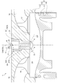
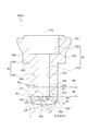
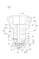
- FIG. 1 is a cross-sectional view schematically showing a sub-chamber gas engine according to an embodiment of the present invention. It is a schematic sectional drawing of the subchamber formation part in one Embodiment. It is a schematic sectional drawing of the subchamber formation part in other one Embodiment, Comprising: It is a figure for demonstrating the outer side recessed part formed in the outer peripheral surface which faces the main combustion chamber of a front-end
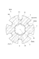
- FIG. 6 is a schematic cross-sectional view taken along line B-B in FIG. It is a schematic sectional drawing of the subchamber formation part in other one Embodiment, Comprising: It is a figure for demonstrating the inner recessed part formed in the internal peripheral surface which faces the subchamber of a front-end
- expressions that indicate that things such as “identical”, “equal” and “homogeneous” are equal states not only represent strictly equal states, but also have tolerances or differences with which the same function can be obtained. It also represents the existing state.
- expressions representing shapes such as quadrilateral shapes and cylindrical shapes not only represent shapes such as rectangular shapes and cylindrical shapes in a geometrically strict sense, but also uneven portions and chamfers within the range where the same effect can be obtained. The shape including a part etc. shall also be expressed.
- the expressions “comprising”, “having”, “having”, “including” or “having” one component are not exclusive expressions excluding the presence of other components.
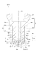
- FIG. 1 is a cross-sectional view schematically showing a sub-chamber type gas engine according to an embodiment of the present invention.
- a sub-chamber gas engine 1 according to some embodiments includes a main chamber forming portion 2 that forms a main combustion chamber 20 (main chamber) of the engine, a main combustion chamber 20 and a plurality of main combustion chambers 20. And a sub-chamber forming portion 3 forming a sub-chamber 30 communicated through the injection hole 4.
- the sub-chamber gas engine 1 has a cylinder block 11 having a cylindrical structure inside, and a cylinder head having a hollow structure capable of covering the top of the cylinder structure. And a piston 14 accommodated in the cylinder 13 and reciprocated, and a sub-chamber nozzle 19 made of, for example, a nickel-based alloy.
- the main combustion chamber 20 described above is defined between the cylinder 13 and the piston 14.
- the sub chamber 30 described above is defined by a sub chamber base 19 mounted on the cylinder head 12 so as to be located at the upper portion (opposite to the piston 14) of the main combustion chamber 20. That is, the main chamber forming portion 2 is formed by the cylinder 13 and the piston 14, and the sub chamber forming portion 3 is formed by the sub chamber cap 19.
- the sub-chamber forming portion 3 has a plurality of injection holes 4 communicating the sub-chamber 30 formed therein with the outside, and via the plurality of injection holes 4.
- the main combustion chamber 20 and the sub chamber 30 communicate with each other.
- the sub-chamber forming portion 3 is a cylindrical small-diameter cylindrical chamber 310 having a predetermined inner diameter, and forms a small-diameter cylindrical chamber 310 to which a plurality of injection holes 4 are connected. It is comprised by the cylinder formation part 31 and the large diameter cylinder formation part 32 which forms the cylindrical large diameter cylinder chamber 320 which has an internal diameter larger than the small diameter cylinder chamber 310.
- the sub chamber 30 includes the small diameter cylindrical chamber 310 and the large diameter cylindrical chamber 320.
- the sub chamber 30 may have another shape such as a cylindrical shape having a constant inner diameter.
- the subchamber central axis CS is the central axis of the small diameter cylindrical chamber 310.
- the main chamber central axis CM and the sub chamber central axis CS coincide with each other, but the sub chamber central axis CS may be inclined with respect to the main chamber central axis CM.
- the central axis of the small diameter cylindrical chamber 310 and the central axis of the large diameter cylindrical chamber 320 do not have to coincide with each other.
- the sub-chamber gas engine 1 includes the igniter 6 provided in the large-diameter cylindrical chamber 320 of the sub-chamber 30 and the fuel for the sub-chamber 30 without the main combustion chamber 20. And a sub-chamber gas supply device 7 for directly supplying gas.
- the ignition device 6 has an ignition unit 61 capable of igniting (igniting) the air-fuel mixture.
- the igniter 6 is an igniter plug, and the igniter 6 is installed in the engine so that the electrode (ignition part 61) of the igniter plug is located on the subchamber center axis CS.
- the ignition device 6 may be installed at a position where the ignition unit 61 is separated from the sub chamber central axis CS by a predetermined distance.
- the sub-chamber gas supply device 7 is configured to supply the sub-chamber fuel gas to the large diameter cylindrical chamber 320 as shown in FIG. The supply of the chamber fuel gas is controlled.
- the sub-chamber gas engine 1 includes an intake port 15 and an exhaust port 16 connected around the cylinder head 12, an intake valve 17 for opening and closing the intake port 15, and an exhaust port 16. And an exhaust valve 18 that opens and closes.
- the intake valve 17 opens and the exhaust valve 18 closes.
- the intake valve 17 is opened, a lean premixed mixture of fuel gas and air is introduced into the cylinder 13 from an intake port 15 connected to the intake valve 17. Further, the subchamber fuel gas is introduced into the subchamber 30 by opening the subchamber fuel gas supply valve 71.
- the sub-chamber fuel gas supply valve 71 is closed.
- the lean premixed air introduced into the cylinder 13 via the intake port 15 is compressed with the rise of the piston 14, a portion of each of the plurality of injection holes 4 of the sub chamber 30 is compressed. Are introduced into the sub-chamber 30.
- the lean premixed gas introduced from the main combustion chamber 20 to the sub-chamber 30 mixes with the sub-chamber fuel gas to generate an air-fuel mixture having a concentration suitable for ignition in the sub-chamber 30.
- the air-fuel mixture in the sub-chamber 30 is ignited by the ignition device 6 at a predetermined timing when the piston 14 is positioned near the compression top dead center, the air-fuel mixture in the sub-chamber 30 is burned, and a combustion flame generated by this combustion
- the fuel is ejected from each of the plurality of injection holes 4 to the cylinder 13 to ignite the lean premixed mixture in the cylinder 13, leading to the combustion of the lean premixed mixture in the main combustion chamber 20.
- the temperature of the inner wall of the sub-chamber forming portion 3 and the injection holes 4 sharply. Since a rapid temperature change occurs in the inner wall of the sub chamber forming portion 3 and the injection hole 4 which is rising, a crack may occur in the inner wall of the sub chamber forming portion 3 and the injection hole 4.
- the inventors of the present invention provide a thin region 5 and a thin region 8 in the sub-chamber forming portion 3 as described later, thereby reducing the heat capacity and rigidity around the injection hole 4 and a plurality of injections at the time of temperature rise. By making the temperature distribution (temperature difference) around the hole gentle, it is possible to reduce the thermal stress generated around the injection hole 4 and to suppress the crack generation around the injection hole 4 Found out.
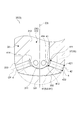
- FIG. 3 is a view for explaining an outer recess formed on the outer peripheral surface of the tip end facing the main combustion chamber.
- FIG. 4 is a schematic cross-sectional view taken along line AA shown in FIG.
- FIG. 5 is a view for explaining an example of a thin region provided at the tip end.
- 6 is a schematic cross-sectional view taken along the line BB in FIG.
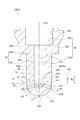
- FIG. 7 is a view for explaining an inner recessed portion formed on the inner peripheral surface facing the sub chamber at the tip end.
- FIG. 8 is a schematic cross-sectional view taken along line CC in FIG.
- the line AA shown in FIG. 3, the line BB shown in FIG. 5, and the line CC shown in FIG. 7 pass the upper end edge 411 of the sub-chamber side opening 41 of the injection hole 4, and the sub-chamber It extends in a direction orthogonal to the central axis CS.
- the sub-chamber central axis CS of the sub-chamber forming portion 3 extends. It includes a cylindrical portion 34 extending along a direction (vertical direction in the drawing) and a tip portion 33 that closes one end (lower end) of the cylindrical portion 34 on the main combustion chamber 20 side.
- the cylindrical portion 34 is a cylindrical large diameter cylindrical portion having a cylindrical small diameter cylindrical portion 341 and an outer diameter larger than the small diameter cylindrical portion 341 as shown in FIGS.
- a stepped surface 343 is formed between the outer peripheral surface 344 of the small diameter cylindrical portion 341 and the outer peripheral surface 345 of the large diameter cylindrical portion 342.
- the sub chamber forming portion 3 abuts the step surface 343 of the cylindrical portion 34 on a portion (not shown) of the cylinder head 12 or contacts the cylinder head 12 via a sealing member or the like (not shown). It is supported by Further, the large diameter cylindrical chamber 320 in the sub-chamber forming portion 3 is formed in a cylindrical shape having a constant inner diameter, and a step between the wall surface 321 of the large diameter cylindrical chamber 320 and the wall surface 312 of the small diameter cylindrical chamber 310 A face 322 is formed.
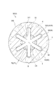
- the tip end portion 33 is internally formed with a plurality of injection holes 4 in which the center line CP is provided to be inclined with respect to the sub chamber center axis CS. .
- the injection hole diameter of the injection hole 4 is D
- the injection hole length is L.
- the injection hole diameter D and the injection hole length L are determined by the combustion performance of the auxiliary chamber gas engine 1 and the internal pressure of the auxiliary chamber forming portion 3.
- the plurality of injection holes 4 are provided at intervals in the circumferential direction as shown in FIGS. 4, 6 and 8.
- the tip end portion 33 is located on the opposite side of the upper end portion of the small diameter cylindrical portion 341 integrally formed with the large diameter cylindrical portion 342. It is integrally formed at the lower end.
- the distal end portion 33 is formed to project from the lower end portion of the small diameter cylindrical portion 341 and has a convex curved tip end surface 332 as shown in FIGS.
- the tip end portion 33 is formed to be recessed inward from the lower end portion of the small diameter cylindrical portion 341, and may have a concave curved tip end surface.
- the distal end portion 33 may be formed to extend along a direction orthogonal to the extension direction of the sub-chamber central axis CS, and may have a flat distal end surface.
- the tip end portion 33 has a thin region 5 having a thickness T satisfying T ⁇ L. doing.
- the tip portion 33 of the sub chamber forming portion 3 has the thin region 5 in which the thickness T satisfies T ⁇ L. ing. Since the plurality of injection holes 4 are formed inside the distal end portion 33, the thin region 5 is formed around the injection holes 4.
- the heat capacity and rigidity around the plurality of injection holes 4 can be reduced, The temperature distribution (temperature difference) around the plurality of injection holes 4 at the time of temperature rise can be made gentle.
- thermal deformation thermal expansion and thermal contraction
- the heat generated around the plurality of injection holes 4 is generated. It is possible to reduce the thermal stress caused by the strain and the thermal strain being restrained.
- the temperature distribution around the plurality of injection holes 4 gentle at the time of temperature rise, it is possible to suppress non-uniform thermal deformation around the injection holes 4, so thermal strain generated around the plurality of injection holes 4 And the thermal stress which arises by constraining the thermal strain can be reduced.
- the occurrence of a crack around the injection hole 4 due to thermal fatigue can be suppressed.
- the thin-walled area 5 described above is an area including the tip 331 of the tip 33.
- the distal end 331 of the distal end portion 33 is, as shown in FIGS. 2 and 5, an end opposite to the end integrally connected with the cylindrical portion 34 in the extension direction of the subchamber central axis CS. is there.
- the sub-chamber forming portion 3 includes sub-chamber forming portions 3A and 3C having a thin area 5 including the first thin area 51.
- the tip end portion 33 of the sub chamber forming portions 3A and 3C is a tip end more than the lower end edge 422 of the main combustion chamber side opening 42 of the injection hole 4 in the extension direction of the sub chamber central axis CS.
- the thickness gradually decreases toward the tip 331 side.
- the first thin-walled region 51 extends from the tip end 331 to a lower side than the lower edge 412 of the sub-chamber side opening 41 of the injection hole 4 in the extension direction of the sub-chamber central axis CS. It is formed.
- the first thin region 51 does not include the peripheral edge of the injection hole 4, that is, the sub chamber side opening 41 of the injection hole 4 and the main combustion chamber side opening 42.
- the thin-walled region 5 (first thin-walled region 51) is a region including the tip end 331 of the tip end portion 33, compared to the case where the tip end 331 of the tip end portion 33 does not have the thin-walled region 5;
- the thickness of the tip end 331 of the tip end portion 33 can be reduced. Therefore, the heat capacity and rigidity around the injection hole 4 can be reduced, and the temperature distribution around the plurality of injection holes 4 at the time of temperature rise can be made gentle. Crack generation can be suppressed.
- the thin regions 5 are circumferentially adjacent to the tip 33 at the tip 33.
- the sub-chamber forming portion 3 in the plane passing through the upper end edge 411 of the sub-chamber side opening 41 of the injection hole 4 and extending in the direction orthogonal to the sub-chamber central axis CS.
- a part of the thickness T1 in the circumferential direction has the same length as the injection hole length L of the injection hole 4 described above.
- the sub-chamber forming portion 3 includes the sub-chamber forming portion 3 B having the thin area 5 including the second thin area 52.
- the sub-chamber forming portion 3C has a thin region 5 including the second thin region 52, in addition to the first thin region 51 described above.
- the second thin region 52 is formed at the tip end portion 33 between the pair of injection holes 4 adjacent in the circumferential direction of the tip end portion 33.
- the sub-chamber forming portion 3 includes a sub-chamber forming portion 3D having a thin-walled region 5 including the third thin-walled region 53.
- the third thin region 53 is formed at the tip end portion 33 between the pair of injection holes 4 adjacent in the circumferential direction of the tip end portion 33.
- the thin-walled region 5 (the second thin-walled region 52, the third thin-walled region 53) is a region including the tip portion 33 between the pair of injection holes 4 adjacent in the circumferential direction of the tip portion 33. Because of this, it is possible to reduce the thickness between the pair of injection holes 4 adjacent in the circumferential direction. For this reason, the heat capacity and rigidity around the pair of injection holes 4 can be reduced, and the temperature distribution around the pair of injection holes 4 at the time of temperature rise can be made gentle. Cracks around 4 can be suppressed.
- the second thin-walled region 52 described above is formed on the outer peripheral surface (tip end surface 332, outer peripheral surface 333) of the distal end portion 33 facing the main combustion chamber 20, as shown in FIGS.
- At least one outer recess 36, 37 (recess 35).
- the outer recesses 36 and 37 extend at least from the lower end edge 422 of the main combustion chamber side opening 42 to the upper end edge 411 of the auxiliary chamber side opening 41 in the extending direction of the auxiliary chamber central axis CS. It is formed over.
- FIGS. 1 the outer recess 36, 37
- a plurality of outer recesses 36, 37 are formed in the tip 33, the plurality of outer recesses 36, 37 being spaced apart from one another in the circumferential direction of the tip 33, And, it is provided between a pair of injection holes 4 adjacent in the circumferential direction of the tip end portion 33.
- the sub-chamber forming portion 3B is an outer recess 36 on the tip 33 side or the tip 33 of the step surface 343 of the cylindrical portion 34 in the extension direction of the sub-chamber central axis CS.
- the wall thickness of the portion where is not formed is formed to be constant.
- the plurality of outer recesses 36 are formed in a slit shape extending from the tip end surface 332 of the tip end portion 33 to the step surface 343 of the cylindrical portion 34 in the extension direction of the subchamber central axis CS, as shown in FIG. There is.
- the plurality of outer recesses 36 are recessed from the tip end surface 332 of the tip end portion 33 and the outer peripheral surface 344 of the small diameter cylindrical portion 341 so as to have an arc-shaped bottom on the inner side (side facing the sub chamber 30) It is done. For this reason, as shown in FIG. 4, the thickness T of the portion where the outer recess 36 is formed in the circumferential direction of the tip end portion 33 is greater than the thickness T1 of the portion where the outer recess 36 is not formed in the circumferential direction. It is formed small.
- the thickness T1 has the same length as the injection hole length L of the injection hole 4 as described above.
- the sub-chamber forming portion 3C is located on the tip 33 side of the step surface 343 of the cylindrical portion 34 in the extending direction of the sub-chamber central axis CS and the main of the injection hole 4
- the thickness of a portion where the outer recess 37 is not formed on the side of the cylindrical portion 34 of the tip end portion 33 including the lower end edge 422 of the combustion chamber side opening 42 is formed to be constant.
- the plurality of outer recesses 37 are formed in a slit shape extending from the tip end surface 332 of the tip end 33 to the lower end of the small diameter cylindrical portion 341 in the extension direction of the subchamber central axis CS, as shown in FIG. There is.
- the plurality of outer recesses 37 are arc-shaped inward (to face the sub chamber 30) from the outer peripheral surface 333 of the distal end portion 33 and the outer peripheral surface 344 of the small diameter cylindrical portion 341 so as to have a constant depth. It is concavely formed to have a bottom surface. For this reason, as shown in FIG. 6, the thickness T of the portion where the outer recess 37 is formed in the circumferential direction of the tip end portion 33 is greater than the thickness T1 of the portion where the outer recess 37 is not formed in the circumferential direction. It is formed small.
- the thickness T1 has the same length as the injection hole length L of the injection hole 4 as described above.
- the thin-walled region 5 (the second thin-walled region 52) is at least one outer recess formed on the outer peripheral surface (the end surface 332, the outer peripheral surface 333) of the tip 33 facing the main combustion chamber 20. 36 and 37 are included. That is, since the thin-walled region 5 is defined by the at least one outer recess 36, 37 formed on the outer peripheral surface of the tip 33, thermal strain generated around the main combustion chamber side opening 42 of the plurality of injection holes 4 and It is possible to reduce the thermal stress caused by the thermal strain being constrained. In addition, it is easy to form the outer side recessed parts 36 and 37 in the outer peripheral surface of the tip part 33 by cutting etc., for example.
- the third thin region 53 described above is formed on the inner circumferential surface (bottom surface 311, wall surface 312) of the distal end portion 33 facing the sub-chamber 30, as shown in FIGS. It is configured to include at least one inner recess 38 (recess 35). As shown in FIG. 7, the inner recess 38 is formed at least from the lower end edge 422 of the main combustion chamber side opening 42 to the upper end edge 411 of the auxiliary chamber side opening 41 in the extension direction of the auxiliary chamber central axis CS. There is. In the embodiment shown in FIG.
- a plurality of inner recesses 38 are formed in the tip 33, and the plurality of inner recesses 38 are spaced apart from one another in the circumferential direction of the tip 33 and It is provided between a pair of injection holes 4 adjacent in the circumferential direction.
- the sub-chamber forming portion 3D is an inner recess 38 on the tip 33 side or the tip 33 of the step surface 343 of the cylindrical portion 34 in the extension direction of the sub-chamber central axis CS.
- the wall thickness of the portion where is not formed is formed to be constant.
- the plurality of inner recesses 38 are formed in a slit shape extending from the bottom surface 311 of the small diameter cylindrical chamber 310 to the step surface 322 of the large diameter cylindrical chamber 320 in the extending direction of the subchamber central axis CS, as shown in FIG. ing.
- the plurality of inner recesses 38 are recessed from the bottom surface 311 and the wall surface 312 of the small diameter cylindrical chamber 310 so as to have a circular arc bottom surface on the inner side (side facing the main combustion chamber 20) so as to be a fixed depth. It is done.
- the plurality of inner recesses 38 are connected to each other at the bottom surface 311 of the small diameter cylindrical chamber 310, as shown in FIG. For this reason, as shown in FIG. 8, the thickness T of the portion where the inner recess 38 is formed in the circumferential direction of the tip end portion 33 is greater than the thickness T1 of the portion where the inner recess 38 is not formed in the circumferential direction. It is formed small.
- the thickness T1 has the same length as the injection hole length L of the injection hole 4 as described above.
- the thin-walled region 5 (third thin-walled region 53) includes at least one inner recess 38 formed on the inner peripheral surface (bottom surface 311, wall surface 312) facing the sub-chamber 30 of the tip end portion 33. It consists of That is, since the thin-walled region 5 is defined by the at least one inner recess 38 formed in the inner peripheral surface of the tip portion 33, the thermal strain and heat generated around the sub chamber side opening 41 of the plurality of injection holes 4 It is possible to reduce the thermal stress caused by the restraint of strain.
- the inner recess 38 is formed up to the step surface 343 of the cylindrical portion 34 in the extension direction of the subchamber central axis CS, the inner recess 38 is formed inside the tip 33 by cutting, for example. It is easy to do.
- the recesses 35 (outer recesses 36, 37, inner recess 38) described above are tipped along the extension direction of the subchamber central axis CS. It extends from the portion 33 over at least a portion of the tubular portion 34 beyond the reference plane RP described above.
- the recess 35 extends from the tip 33 to at least a part of the cylindrical portion 34 along the extension direction of the subchamber central axis CS, so the tip 33 side of the cylindrical 34
- the wall thickness is formed thin at least in part.
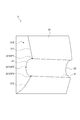
- FIG. 9 is a schematic cross-sectional view showing an enlarged vicinity of a tip end portion of the sub chamber forming portion in another embodiment, and is for explaining a chamfered shape formed on the periphery of the sub chamber side opening of the injection hole.
- the sub-chamber forming portion 3 includes a sub-chamber forming portion 3E having a chamfered portion 414 in the sub-chamber side opening 41 described above.
- the sub-chamber forming portion 3E has the same configuration as the sub-chamber forming portion 3C except that a chamfered portion 414 having a C-chamfered shape is provided all around the periphery of the sub-chamber side opening 41. There is.
- the chamfer 414 in the sub chamber side opening 41 of sub chamber formation part 3A, 3B, 3D and 3 G mentioned later.
- the chamfered portion may be formed over the entire circumference of the main combustion chamber side opening 42.
- the sub-chamber forming portion 3E has the chamfered portion 414 in the sub-chamber side opening 41, and thus constitutes the sub-chamber side opening 41 as compared with the case where the chamfered portion 414 is not provided. Since the temperature of the portion can be reduced, it is possible to reduce the thermal strain generated around the sub-chamber side openings 41 of the plurality of injection holes 4 and the thermal stress generated by the thermal strain being restrained.
- the stress analysis was performed based on the temperature analysis and the temperature analysis results for the sub-chamber forming unit 3 in the sub-chamber type gas engine 1 according to some embodiments described above. The details will be described below.
- the temperature change of the sub-chamber forming part 3 was estimated by applying the thermal conditions such as the change of the ambient temperature and the heat transfer coefficient at the time of engine operation according to each surface such as the bottom surface 311 and the wall surface 312. .
- FIG. 10 is a view for explaining temperature analysis results and stress analysis results around the injection hole of the sub chamber formation portion.
- the sub chamber side opening 41 of the injection hole 4 shown in FIG. 10 has a rapid temperature change as compared with the other portion of the sub chamber forming portion 3 and the sub chamber forming portion 3 It becomes hotter than other parts.
- stress analysis was performed to estimate a strain change, and a strain range at each of the measurement points P1 to P3 was calculated.
- the measurement point P1 is located on the upper end edge 411 of the sub chamber side opening 41
- the measurement point P3 is located on the lower end edge 412 of the sub chamber side opening 41.
- the measurement point P2 is located on the middle edge 413 located between the upper end edge 411 and the lower end edge 412 of the sub-chamber side opening 41 in the extension direction of the sub-chamber central axis CS.
- the sub-chamber side opening 41 as described above has the chamfered portion 414, as shown in FIG. 9, the upper end edge 411, the lower end edge 412 and the middle edge of the chamfered portion 414 on the periphery of the main combustion chamber 20 side. 413 are provided.
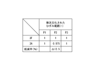
- FIG. 11 is a chart showing a non-dimensionalized strain range in the sub-chamber side opening of the sub-chamber forming part having the first thin-walled region, for comparison with the sub-chamber forming part having no thin-walled region. is there.
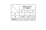
- FIG. 12 is a chart showing a non-dimensionalized strain range in the sub-chamber side opening of the sub-chamber forming portion having a chamfered shape formed on the periphery of the first thin region, the second thin region and the sub-chamber side opening It is a chart for comparing with the subchamber formation part which does not have a thin region.
- 3F in FIGS. 11 and 12 is a sub-chamber forming portion having a tip as shown by a two-dot chain line in FIG. 2 and having no thin region 5.
- the strain range at each measurement point P1 to P3 of the sub chamber forming portion 3F and the sub chamber forming portion 3A is non-dimensionalized and represented at a ratio of 1 to the sub chamber forming portion 3F, and The reduction rate of the chamber forming portion 3A with respect to the sub chamber forming portion 3F is shown.
- the sub-chamber forming portion 3A has the first thin region 51, whereby the strain range at the measurement point P2 is reduced as compared to the sub-chamber forming portion 3F. Therefore, the sub-chamber forming portion 3A can suppress the occurrence of a crack generated between the pair of injection holes 4 adjacent to each other in the circumferential direction, as compared to the sub-chamber forming portion 3F.
- the strain range at each measurement point P1 to P3 of the sub-chamber forming portion 3F and the sub-chamber forming portion 3E is non-dimensionalized and represented at a ratio of 1 to the sub-chamber forming portion 3F.
- a reduction rate of the chamber forming portion 3E with respect to the sub chamber forming portion 3F is shown.
- the sub-chamber forming portion 3E includes the first thin region 51, the second thin region 52, and the chamfered portion 414 of the sub-chamber side opening 41, so that the sub-chamber forming portion 3E can be compared to the sub-chamber forming portion 3F.
- the strain range at all the measurement points P1 to P3 is reduced.
- the sub-chamber forming portion 3E has a larger reduction rate to the sub-chamber forming portion 3F than the sub-chamber forming portion 3A shown in FIG. Therefore, the sub-chamber forming portion 3E can reduce the thermal stress generated around the plurality of injection holes 4 and can suppress the occurrence of the crack, as compared with the sub-chamber forming portions 3A and 3F.
- the tip end portion 33 has the thin-walled region 5 which is a region where the thickness T satisfies T ⁇ L, but in some embodiments described later, the tip end portion 33 is It has a thin region 8 in which the thickness T satisfies T ⁇ T0. The details will be described below.
- the sub chamber forming portion 3 in the sub chamber type gas engine 1 has the sub chamber central axis CS of the sub chamber forming portion 3 extended. It includes the above-described cylindrical portion 34 extending along the existing direction (vertical direction in the figure), and the above-described tip portion 33 closing the one end portion (lower end portion) of the cylindrical portion 34 on the main combustion chamber 20 side. It is.
- FIG. 13 is a schematic cross-sectional view of the sub chamber forming portion in another embodiment.
- the main combustion chamber 20 side ( A surface passing through a position 346 separated by a reference length RL in the direction opposite to the lower side in the drawing) and extending in a direction orthogonal to the subchamber central axis CS is taken as a reference surface RP.
- the reference length RL is three times (predetermined times) the injection hole diameter D of the injection hole 4.
- the tip 33 is located closer to the main combustion chamber 20 than the reference plane RP, as shown in FIGS. 2, 3, 5, 7 and 13.
- the reference surface RP is apart from the injection hole 4 and the influence of the heat produced by the above-described combustion flame is small.
- the tip 33 located closer to the main combustion chamber 20 than the reference surface RP is largely affected by the heat produced by the above-described combustion flame. For this reason, the distal end portion 33 is more effective than the cylindrical portion 34 by providing the thin region 8.
- the tip portion 33 has a thickness T of T ⁇ T0. It has a thin area 8 which is an area to be filled.
- a surface of the sub chamber forming portion 3 which passes through the upper end edge 411 of the sub chamber side opening 41 of the injection hole 4 and extends in a direction orthogonal to the sub chamber central axis CS Between the reference plane RP and the reference plane RP, the sectional shape along the direction orthogonal to the subchamber central axis CS is formed in the same cylindrical shape.
- the tip portion 33 passes the upper end edge 411 of the sub chamber side opening 41 of the injection hole 4, and a part of the circumferential direction in the cross section extending in the direction orthogonal to the sub chamber central axis CS It has the same thickness T1 as the thickness T0 in the plane RP.
- the thickness T1 has the same length as the injection hole length L of the injection hole 4 described above.
- the thickness in the circumferential direction is not constant, but in this case, the maximum thickness in the circumferential direction is the thickness T0 or the thickness T1 described above.
- the thin area 8 includes a first thin area 81 which is the same as the first thin area 51 of the thin area 5 described above.
- the thin area 8 includes a second thin area 82 which is the same as the second thin area 52 of the thin area 5 described above. Therefore, the second thin-walled region 82 is a region including the space between the pair of injection holes 4 adjacent in the circumferential direction of the distal end portion 33 at the distal end portion 33. Further, the second thin-walled region 82 is configured to include at least one outer concave portion 36, 37 formed on the outer peripheral surface (the front end surface 332, the outer peripheral surface 333) of the front end portion 33 facing the main combustion chamber 20. .
- the thin area 8 includes a third thin area 83 which is the same as the third thin area 53 of the thin area 5 described above.
- the third thin-walled region 83 is a region in the tip end portion 33 that includes between the pair of injection holes 4 adjacent in the circumferential direction of the tip end portion 33.
- the third thin region 83 is configured to include at least one inner recess 38 (recess 35) formed on the inner peripheral surface (bottom surface 311, wall surface 312) of the distal end portion 33 facing the sub chamber 30. .
- the sub-chamber forming portion 3 includes a sub-chamber forming portion 3G having a thin area 8 including the fourth thin area 84.
- the tip end portion 33 of the sub chamber forming portion 3G is closer to the cylindrical portion 34 than the upper end edge 421 of the main combustion chamber side opening 42 of the injection hole 4 in the extension direction of the sub chamber central axis CS.
- the thickness gradually decreases toward the tip end 331, and the thickness is constant on the tip end 331 side of the upper end edge 421, and the thickness is equal to the injection hole length L1.
- the thickness T of the distal end portion 33 is formed smaller than the thickness T0 in the reference plane RP.
- the fourth thin-walled region 84 is formed from the tip end 331 to a position above the upper end edge 421 of the main combustion chamber side opening 42 of the injection hole 4 in the extension direction of the subchamber central axis CS. There is.
- the tip end portion 33 of the sub chamber forming portion 3 extends along the direction in which the sub chamber central axis CS extends from the upper end edge 411 of the sub chamber side opening 41 of the injection hole 4. It passes through a reference length RL in a direction opposite to the side, that is, a position 346 separated by a length three times (predetermined multiple) of the injection hole diameter D of the injection hole 4 and orthogonal to the subchamber central axis CS. It is located closer to the main combustion chamber 20 than the reference plane RP extending in the direction.
- the tip portion 33 has a thin region 8 in which the thickness T satisfies T ⁇ T0, where T0 is the thickness of the sub-chamber forming portion 3 on the reference surface RP.
- the thin-walled region 8 has a thickness T smaller than that of the reference surface RP where the influence of the heat produced by the combustion flame is small.
- the thin-walled area 8 (first thin-walled area 81, fourth thin-walled area 84) described above is an area including the tip 331 described above.
- the thin-walled area 8 (first thin-walled area 81, fourth thin-walled area 84) is an area including the tip end 331 of the tip end portion 33, the tip end 331 of the tip end portion 33 has the thin-walled area 8
- the thickness of the tip end 331 of the tip end portion 33 can be reduced as compared with the case of not performing. Therefore, the heat capacity and rigidity around the injection hole 4 can be reduced, and the temperature distribution around the plurality of injection holes 4 at the time of temperature rise can be made gentle. Crack generation can be suppressed. It is easy to form the thin region 8 including the tip 331 of the tip 33 by cutting, for example, with respect to the sub-chamber forming part 3 which does not have the thin region 8 at the tip 331 of the tip 33.
- the thin-walled area 8 (fourth thin-walled area 84) mentioned above is at least a part of the periphery of the main combustion chamber side opening 42 of the injection hole 4 at the tip 33.
- the peripheral edge of the main combustion chamber side opening 42 includes an upper end edge 421 and a lower end edge 422 as shown in FIG. 13.
- the fourth thin region 84 includes both the upper end edge 421 and the lower end edge 422 of the main combustion chamber side opening 42 of the injection hole 4.
- the thin-walled region 8 (fourth thin-walled region 84) is a region including at least a part of the peripheral edge of the main combustion chamber side opening 42 of the injection hole 4 at the tip end portion 33.
- the wall thickness around can be reduced. Therefore, the heat capacity and rigidity around the injection hole 4 can be reduced, and the temperature distribution around the plurality of injection holes 4 at the time of temperature rise can be made gentle. Crack generation can be suppressed.
- the reference length RL which is the length between the top edge 411 and the position 346 described above, The length is 3 times (predetermined times) the injection hole diameter D of the hole 4, but the reference length RL may be longer or shorter than 3 times the injection hole diameter D, for example, the injection of the injection hole 4 It may be one or twice as long as the pore diameter D. Also, the reference length RL may be zero. Further, when the reference length RL is short or zero, the reference plane RP may be provided at a position corresponding to the reference length RL. When the reference length RL is shortened, the range of the tip end 33 is narrowed, and accordingly, the thin region 8 is also formed around the injection hole 4. For this reason, compared with the case where the reference length RL is increased, it is possible to reduce the thermal strain generated around the plurality of injection holes 4 and the thermal stress generated by the thermal strain being restrained.
- the thin-walled region 5 is a region in which the thickness T satisfies T ⁇ T0
- the thin-walled region 8 is a region in which the thickness T satisfies T ⁇ L.
- the thickness T of the thin region 5 and the thin region 8 has the minimum thickness that can withstand the internal pressure applied to the sub-chamber forming portion 3 .
- the thickness T is small, the strength decreases as compared with the case where the thickness T is large, but the heat capacity and rigidity around the plurality of injection holes 4 can be reduced, and the heat generated around the plurality of injection holes 4 Stress can be reduced.
- the thin region 5 and the thin region 8 are in the above-described range, the sub-chamber forming portion 3 can effectively suppress the crack generation while maintaining the necessary strength.
- the thin region 5 and the thin region 8 do not include the peripheries of the sub chamber side opening 41 and the main combustion chamber side opening 42 of the injection hole 4. In this case, since the injection hole diameter D of the injection hole 4 and the injection hole length L are maintained, the performance of the combustion flame ejected from the injection hole 4 can be maintained.
- the recess 35 is formed along the extension direction of the sub chamber central axis CS, but may be formed along another direction.
- the recess may be formed along the circumferential direction of the distal end portion 33 or the cylindrical portion 34.
- the present invention is not limited to the above-described embodiments, and includes the embodiments in which the above-described embodiments are modified, and the embodiments in which these embodiments are appropriately combined.
Abstract
This auxiliary chamber type gas engine is provided with a main chamber forming portion for forming a main combustion chamber, and an auxiliary chamber forming portion for forming an auxiliary chamber which communicates with the main combustion chamber by way of a plurality of injection holes. The auxiliary chamber forming portion includes a cylindrical portion extending in the direction in which an auxiliary chamber central axis of the auxiliary chamber forming portion extends, and a distal end portion which blocks one end portion of the cylindrical portion, on the main combustion chamber side thereof, and in which the injection holes are formed. The distal end portion has a thin walled region, which is a region having a wall thickness T satisfying T<L, where L is the length dimension of the injection holes.
Description
本開示は、副室で生成された燃焼火炎を複数の噴孔を介して、主燃焼室に噴出させることで、主燃焼室の混合気を燃焼させる副室式ガスエンジンに関する。
The present disclosure relates to a sub-chamber gas engine that burns an air-fuel mixture in a main combustion chamber by causing a combustion flame generated in the sub-chamber to be ejected to the main combustion chamber through a plurality of injection holes.
従来から、ピストンとシリンダヘッドとの間に画定される主燃焼室(主室)と、該主燃焼室と複数の噴孔を介して連通される副燃焼室(副室)と、を備える副室式ガスエンジンが知られている(例えば、特許文献1)。副室式ガスエンジンは、点火プラグなどの着火装置により副室の混合気を着火し、該着火により生じた燃焼火炎が副室の先端に設けられた複数の噴孔の各々から噴出することで、主燃焼室の希薄予混合気を燃焼させる。
Conventionally, a sub combustion chamber (main chamber) defined between a piston and a cylinder head, and a sub combustion chamber (sub chamber) communicated with the main combustion chamber via a plurality of injection holes. A room-type gas engine is known (for example, patent document 1). The sub-chamber gas engine ignites the air-fuel mixture in the sub-chamber by an ignition device such as a spark plug, and the combustion flame generated by the ignition is ejected from each of a plurality of injection holes provided at the tip of the sub-chamber. , Burn the lean premixed mixture in the main combustion chamber.
特許文献1には、副室の内壁の温度が1000℃程度まで上昇(昇温)することで内壁が膨張すること、膨張した内壁が温度低下により収縮すること、及び、副室の内壁が膨張と収縮との繰り返しにより熱疲労し、内壁にき裂を生じる虞があることが開示されている。そして、特許文献1には、き裂は噴孔の副室側開口縁近傍に多く発生することも開示されている。
In Patent Document 1, when the temperature of the inner wall of the sub chamber rises (increases temperature) to about 1000 ° C., the inner wall expands, the expanded inner wall shrinks due to the temperature decrease, and the inner wall of the sub chamber expands. It is disclosed that there is a risk of thermal fatigue due to repetition of shrinkage and contraction, and cracking on the inner wall. Further, Patent Document 1 also discloses that a large number of cracks are generated in the vicinity of the auxiliary chamber side opening edge of the injection hole.
上述した課題に対して、特許文献1では、副室側開口縁近傍のき裂発生の原因は、副室側開口縁がその周囲の部位に比べて著しく高温となることにあるとの知見に基づき、開口縁とその周囲の部位との温度差を小さくするために、噴孔の副室側開口縁を一定の曲率半径を有する曲面に形成することが開示されている。
With respect to the problems described above, in Patent Document 1, it is known that the cause of the crack generation in the vicinity of the opening edge of the sub chamber side is that the temperature of the opening edge of the sub chamber side becomes extremely high compared to the surrounding portion. Accordingly, in order to reduce the temperature difference between the opening edge and the surrounding area, it is disclosed to form the subchamber side opening edge of the injection hole into a curved surface having a constant radius of curvature.
確かに特許文献1では、副室側開口縁に上述した曲面を形成しない場合に比べて、副室側開口縁におけるき裂の発生を抑制することができるが、曲面を形成することにより生じる効果は限定的なものであるため、き裂の発生をさらに抑制したい場合には、さらなる方策が必要となる。
Certainly, in Patent Document 1, although the occurrence of a crack at the subchamber side opening edge can be suppressed as compared with the case where the above curved surface is not formed at the subchamber side opening edge, the effect caused by forming the curved surface Is limited, and if it is desired to further suppress the occurrence of cracks, further measures are required.
上述した事情に鑑みて、本発明の少なくとも一実施形態の目的は、噴孔の周囲に生じる熱応力を低減させることができ、且つ、噴孔の周囲のき裂発生を抑制することができる副室式ガスエンジンを提供することにある。
In view of the above-described circumstances, it is an object of at least one embodiment of the present invention to reduce thermal stress generated around the injection hole and to suppress generation of a crack around the injection hole. It is to provide a room-type gas engine.
(1)本発明の少なくとも一実施形態に係る副室式ガスエンジンは、
主燃焼室を形成する主室形成部と、
前記主燃焼室と複数の噴孔を介して連通される副室を形成する副室形成部と、を備える副室式ガスエンジンであって、
前記副室形成部は、前記副室形成部の副室中心軸線が延在する方向に沿って延在する筒状部と、前記筒状部の前記主燃焼室側の一端部を塞ぐとともに内部に前記噴孔が形成される先端部と、を含み、
前記先端部は、前記噴孔の長さ寸法をLとした場合に、肉厚TがT<Lを満たす領域である薄肉領域を有する。 (1) A sub-chamber gas engine according to at least one embodiment of the present invention,
A main chamber forming part forming a main combustion chamber,
A sub-chamber gas engine comprising: a sub-chamber forming portion forming a sub-chamber communicated with the main combustion chamber through a plurality of injection holes,
The sub-chamber forming portion closes a cylindrical portion extending along a direction in which the sub-chamber central axis of the sub-chamber forming portion extends, and closes one end portion on the main combustion chamber side of the cylindrical portion. And a tip where the injection hole is formed,
The tip portion has a thin-walled region which is a region where the thickness T satisfies T <L when the length dimension of the injection hole is L.
上記(1)の構成によれば、副室形成部の先端部は、噴孔の長さ寸法をLとした場合に、肉厚TがT<Lを満たす領域である薄肉領域を有している。先端部の内部には複数の噴孔が形成されているため、上記薄肉領域は、噴孔の周囲に形成されることとなる。このような薄肉領域が、燃焼火炎がもたらす熱の影響が大きい先端部の噴孔の周囲に形成されることで、複数の噴孔の周囲の熱容量や剛性を小さくすることや、昇温時における複数の噴孔の周囲の温度分布(温度差)を緩やかにすることができる。複数の噴孔の周囲の熱容量や剛性を小さくすることで、複数の噴孔の周囲における熱変形(熱膨張や熱収縮)がし易くなるため、複数の噴孔の周囲に生じる熱ひずみ及び該熱ひずみが拘束されることで生じる熱応力を低減できる。また、昇温時における複数の噴孔の周囲の温度分布を緩やかにすることで、噴孔の周囲における不均一な熱変形を抑制できるため、複数の噴孔の周囲に生じる熱ひずみ及び該熱ひずみが拘束されることで生じる熱応力を低減できる。よって、熱疲労による噴孔の周囲のき裂発生を抑制することができる。
According to the configuration of the above (1), when the length dimension of the injection hole is L, the tip end portion of the sub chamber formation portion has a thin region which is a region in which the thickness T satisfies T <L. There is. Since a plurality of injection holes are formed inside the tip end, the thin-walled region is formed around the injection holes. Such a thin-walled region is formed around the injection holes at the tip end portion where the influence of heat caused by the combustion flame is large, thereby reducing the heat capacity and rigidity around the plurality of injection holes, and at the time of temperature rise. The temperature distribution (temperature difference) around the plurality of injection holes can be made gentle. By reducing the heat capacity and rigidity around the plurality of injection holes, thermal deformation (thermal expansion and thermal contraction) around the plurality of injection holes is facilitated, so that thermal strain generated around the plurality of injection holes and the strain It is possible to reduce the thermal stress caused by the thermal strain being restrained. In addition, by making the temperature distribution around the plurality of injection holes gentler at the time of temperature rise, it is possible to suppress non-uniform thermal deformation around the injection holes, so the thermal strain generated around the plurality of injection holes and the heat It is possible to reduce the thermal stress caused by the restraint of strain. Therefore, the crack generation around the injection hole due to thermal fatigue can be suppressed.
(2)本発明の少なくとも一実施形態に係る副室式ガスエンジンは、
主燃焼室を形成する主室形成部と、
前記主燃焼室と複数の噴孔を介して連通される副室を形成する副室形成部と、を備える副室式ガスエンジンであって、
前記副室形成部は、前記副室形成部の副室中心軸線が延在する方向に沿って延在する筒状部と、前記筒状部の前記主燃焼室側の一端部を塞ぐとともに内部に前記噴孔が形成される先端部と、を含み、
前記先端部は、前記噴孔の前記副室側の開口の上端縁から前記副室中心軸線が延在する方向に沿って、前記主燃焼室側とは反対の方向に前記噴孔の噴孔径の所定倍の長さだけ離れた位置において前記副室中心軸線と直交する方向に延在する基準面よりも前記主燃焼室側に位置するとともに、
前記基準面における前記副室形成部の肉厚をT0とした場合に、肉厚TがT<T0を満たす領域である薄肉領域を有する。 (2) A sub-chamber type gas engine according to at least one embodiment of the present invention,
A main chamber forming part forming a main combustion chamber,
A sub-chamber gas engine comprising: a sub-chamber forming portion forming a sub-chamber communicated with the main combustion chamber through a plurality of injection holes,
The sub-chamber forming portion closes a cylindrical portion extending along a direction in which the sub-chamber central axis of the sub-chamber forming portion extends, and closes one end portion on the main combustion chamber side of the cylindrical portion. And a tip where the injection hole is formed,
The tip end portion has an injection hole diameter of the injection hole in a direction opposite to the main combustion chamber side along a direction in which the sub chamber central axis extends from an upper end edge of the opening on the sub chamber side of the injection hole. And at a position separated by a predetermined multiple of the length of the second chamber, the second combustion chamber is located closer to the main combustion chamber than a reference surface extending in a direction perpendicular to the subchamber center axis.
When the thickness of the sub-chamber forming portion on the reference surface is T0, there is a thin region which is a region where the thickness T satisfies T <T0.
上記(2)の構成によれば、副室形成部の先端部は、噴孔の副室側の開口の上端縁から副室中心軸線が延在する方向に沿って、主燃焼室側とは反対の方向に噴孔の噴孔径の例えば3倍等の所定倍の長さだけ離れた位置において副室中心軸線と直交する方向に延在する基準面よりも主燃焼室側に位置している。そして、先端部は、上記基準面における副室形成部の肉厚をT0とした場合に、肉厚TがT<T0を満たす領域である薄肉領域を有している。すなわち、薄肉領域は、燃焼火炎がもたらす熱の影響が小さい基準面よりも肉厚が薄い。このような薄肉領域が、燃焼火炎がもたらす熱の影響が大きい先端部の噴孔の周囲に形成されることで、複数の噴孔の周囲の熱容量や剛性を小さくすることや、昇温時における複数の噴孔の周囲の温度分布(温度差)を緩やかにすることができる。複数の噴孔の周囲の熱容量や剛性を小さくすることで、複数の噴孔の周囲における熱変形(熱膨張や熱収縮)がし易くなるため、複数の噴孔の周囲に生じる熱ひずみ及び該熱ひずみが拘束されることで生じる熱応力を低減できる。また、昇温時における複数の噴孔の周囲の温度分布を緩やかにすることで、噴孔の周囲における不均一な熱変形を抑制できるため、複数の噴孔の周囲に生じる熱ひずみ及び該熱ひずみが拘束されることで生じる熱応力を低減できる。よって、熱疲労による噴孔の周囲のき裂発生を抑制することができる。
According to the configuration of the above (2), the tip end portion of the sub chamber formation portion extends from the upper end edge of the opening on the sub chamber side of the injection hole along the sub chamber central axis line to the main combustion chamber side It is located closer to the main combustion chamber side than a reference surface extending in a direction perpendicular to the subchamber center axis at a position separated by a predetermined multiple of, for example, three times the injection hole diameter of the injection hole in the opposite direction. . The tip portion has a thin-walled region which is a region where the thickness T satisfies T <T0, where T0 is the thickness of the sub-chamber forming portion in the reference surface. That is, the thin-walled region is thinner than the reference surface which is less affected by the heat produced by the combustion flame. Such a thin-walled region is formed around the injection holes at the tip end portion where the influence of heat caused by the combustion flame is large, thereby reducing the heat capacity and rigidity around the plurality of injection holes, and at the time of temperature rise. The temperature distribution (temperature difference) around the plurality of injection holes can be made gentle. By reducing the heat capacity and rigidity around the plurality of injection holes, thermal deformation (thermal expansion and thermal contraction) around the plurality of injection holes is facilitated, so that thermal strain generated around the plurality of injection holes and the strain It is possible to reduce the thermal stress caused by the thermal strain being restrained. In addition, by making the temperature distribution around the plurality of injection holes gentler at the time of temperature rise, it is possible to suppress non-uniform thermal deformation around the injection holes, so the thermal strain generated around the plurality of injection holes and the heat It is possible to reduce the thermal stress caused by the restraint of strain. Therefore, the crack generation around the injection hole due to thermal fatigue can be suppressed.
(3)幾つかの実施形態では、上記(1)の構成において、
前記薄肉領域は、前記先端部における先端を含む領域である。
上記(3)の構成によれば、薄肉領域は、先端部の先端を含む領域であるので、先端部の先端に薄肉領域を有しない場合に比べて、先端部の先端における肉厚を薄くできる。このため、噴孔の周囲の熱容量や剛性を小さくすることや、昇温時における複数の噴孔の周囲の温度分布を緩やかにすることができるので、熱疲労による噴孔の周囲のき裂発生を抑制することができる。 (3) In some embodiments, in the configuration of (1) above,
The thin area is an area including the tip of the tip.
According to the configuration of the above (3), since the thin region is a region including the tip of the tip, the thickness at the tip of the tip can be thinner than in the case where there is no thin region at the tip of the tip. . Therefore, the heat capacity and rigidity around the injection hole can be reduced, and the temperature distribution around the plurality of injection holes can be made gentle at the time of temperature rise, so that the crack generation around the injection hole due to thermal fatigue. Can be suppressed.
(4)幾つかの実施形態では、上記(2)の構成において、
前記薄肉領域は、前記先端部における先端を含む領域である。
上記(4)の構成によれば、薄肉領域は、先端部の先端を含む領域であるので、先端部の先端に薄肉領域を有しない場合に比べて、先端部の先端における肉厚を薄くできる。このため、噴孔の周囲の熱容量や剛性を小さくすることや、昇温時における複数の噴孔の周囲の温度分布を緩やかにすることができるので、熱疲労による噴孔の周囲のき裂発生を抑制することができる。 (4) In some embodiments, in the configuration of (2) above,
The thin area is an area including the tip of the tip.
According to the configuration of the above (4), since the thin region is a region including the tip of the tip, the thickness at the tip of the tip can be thinner than in the case where there is no thin region at the tip of the tip. . Therefore, the heat capacity and rigidity around the injection hole can be reduced, and the temperature distribution around the plurality of injection holes can be made gentle at the time of temperature rise, so that the crack generation around the injection hole due to thermal fatigue. Can be suppressed.
(5)幾つかの実施形態では、上記(2)又は(4)の構成において、
前記薄肉領域は、前記先端部において、前記噴孔の前記主燃焼室側の開口の周縁の少なくとも一部を含む領域である。
上記(5)の構成によれば、薄肉領域は、先端部において、噴孔の主燃焼室側の開口の周縁の少なくとも一部を含む領域であるので、噴孔の周囲の肉厚を薄くすることができる。このため、噴孔の周囲の熱容量や剛性を小さくすることや、昇温時における複数の噴孔の周囲の温度分布を緩やかにすることができるので、熱疲労による噴孔の周囲のき裂発生を抑制することができる。 (5) In some embodiments, in the configuration of (2) or (4) above,
The thin-walled region is a region including at least a part of the peripheral edge of the opening on the main combustion chamber side of the injection hole at the tip end portion.
According to the configuration of the above (5), since the thin-walled region is a region including at least a part of the periphery of the opening on the main combustion chamber side of the injection hole at the tip end portion, the thickness around the injection hole is reduced be able to. Therefore, the heat capacity and rigidity around the injection hole can be reduced, and the temperature distribution around the plurality of injection holes can be made gentle at the time of temperature rise, so that the crack generation around the injection hole due to thermal fatigue. Can be suppressed.
(6)幾つかの実施形態では、上記(1)~(5)の構成において、
前記薄肉領域は、前記先端部において、前記先端部の周方向に隣接する一対の噴孔の間を含む領域である。
上記(6)の構成によれば、薄肉領域は、先端部において、先端部の周方向に隣接する一対の噴孔の間を含む領域であるので、周方向に隣接する一対の噴孔の間の肉厚を薄くできる。このため、前記一対の噴孔の周囲の熱容量や剛性を小さくすることや、昇温時における前記一対の噴孔の周囲の温度分布を緩やかにすることができるので、熱疲労による噴孔の周囲のき裂発生を抑制することができる。 (6) In some embodiments, in the above configurations (1) to (5),
The thin-walled region is a region including, in the tip portion, between a pair of injection holes adjacent in the circumferential direction of the tip portion.
According to the configuration of (6), since the thin-walled region is a region including between the pair of injection holes adjacent in the circumferential direction of the tip end portion at the tip end portion, between the pair of injection holes adjacent in the circumferential direction Can reduce the thickness of the For this reason, the heat capacity and rigidity around the pair of injection holes can be reduced, and the temperature distribution around the pair of injection holes can be made gentle at the time of temperature rise, so the periphery of the injection holes due to thermal fatigue Can suppress the occurrence of cracks in the
(7)幾つかの実施形態では、上記(6)の構成において、
前記薄肉領域は、前記先端部の前記主燃焼室に面する外周面に形成された少なくとも1つの外側凹部を含んで構成されている。
上記(7)の構成によれば、薄肉領域は先端部の主燃焼室に面する外周面に形成された少なくとも1つの外側凹部を含んで構成されている。すなわち、先端部の外周面に形成された少なくとも1つの外側凹部により薄肉領域が画定されているので、複数の噴孔の主燃焼室側開口の周囲に生じる熱ひずみ及び該熱ひずみが拘束されることで生じる熱応力を低減できる。 (7) In some embodiments, in the configuration of (6) above,
The thin-walled region is configured to include at least one outer recess formed on an outer peripheral surface facing the main combustion chamber of the tip end portion.
According to the configuration of the above (7), the thin-walled region is configured to include at least one outer concave portion formed on the outer peripheral surface facing the main combustion chamber of the tip end portion. That is, since the thin region is defined by at least one outer recess formed on the outer peripheral surface of the tip, thermal strain and thermal strain generated around the main combustion chamber side opening of the plurality of injection holes are restrained. Can reduce the thermal stress generated by
(8)幾つかの実施形態では、上記(6)又は(7)の構成において、
前記薄肉領域は、前記先端部の前記副室に面する内周面に形成された少なくとも1つの内側凹部を含んで構成されている。
上記(8)の構成によれば、薄肉領域は先端部の副室に面する内周面に形成された少なくとも1つの内側凹部を含んで構成されている。すなわち、先端部の内周面に形成された少なくとも1つの内側凹部により薄肉領域が画定されているので、複数の噴孔の副室側開口の周囲に生じる熱ひずみ及び該熱ひずみが拘束されることで生じる熱応力を低減できる。 (8) In some embodiments, in the configuration of (6) or (7) above,
The thin-walled region includes at least one inner recess formed on an inner peripheral surface facing the sub-chamber of the tip end.
According to the configuration of the above (8), the thin-walled region is configured to include at least one inner concave portion formed on the inner circumferential surface facing the sub-chamber at the tip end. That is, since the thin region is defined by the at least one inner recess formed on the inner peripheral surface of the tip portion, thermal strain and thermal strain generated around the sub-chamber openings of the plurality of injection holes are restrained. Can reduce the thermal stress generated by
本発明の少なくとも一実施形態によれば、噴孔の周囲に生じる熱応力を低減させることができ、且つ、噴孔の周囲のき裂発生を抑制することができる副室式ガスエンジンが提供される。
According to at least one embodiment of the present invention, there is provided a sub-chamber type gas engine capable of reducing thermal stress generated around the injection hole and suppressing crack generation around the injection hole. Ru.
以下、添付図面を参照して本発明の幾つかの実施形態について説明する。ただし、実施形態として記載されている又は図面に示されている構成部品の寸法、材質、形状、その相対的配置等は、本発明の範囲をこれに限定する趣旨ではなく、単なる説明例にすぎない。
例えば、「ある方向に」、「ある方向に沿って」、「平行」、「直交」、「中心」、「同心」或いは「同軸」等の相対的或いは絶対的な配置を表す表現は、厳密にそのような配置を表すのみならず、公差、若しくは、同じ機能が得られる程度の角度や距離をもって相対的に変位している状態も表すものとする。
例えば、「同一」、「等しい」及び「均質」等の物事が等しい状態であることを表す表現は、厳密に等しい状態を表すのみならず、公差、若しくは、同じ機能が得られる程度の差が存在している状態も表すものとする。
例えば、四角形状や円筒形状等の形状を表す表現は、幾何学的に厳密な意味での四角形状や円筒形状等の形状を表すのみならず、同じ効果が得られる範囲で、凹凸部や面取り部等を含む形状も表すものとする。
一方、一の構成要素を「備える」、「具える」、「具備する」、「含む」、又は、「有する」という表現は、他の構成要素の存在を除外する排他的な表現ではない。 Hereinafter, some embodiments of the present invention will be described with reference to the accompanying drawings. However, the dimensions, materials, shapes, relative arrangements, etc. of the components described as the embodiments or shown in the drawings are not intended to limit the scope of the present invention to this, but are merely illustrative. Absent.
For example, a representation representing a relative or absolute arrangement such as “in a direction”, “along a direction”, “parallel”, “orthogonal”, “center”, “concentric” or “coaxial” is strictly Not only does it represent such an arrangement, but also represents a state of relative displacement with an angle or distance that allows the same function to be obtained.
For example, expressions that indicate that things such as "identical", "equal" and "homogeneous" are equal states not only represent strictly equal states, but also have tolerances or differences with which the same function can be obtained. It also represents the existing state.
For example, expressions representing shapes such as quadrilateral shapes and cylindrical shapes not only represent shapes such as rectangular shapes and cylindrical shapes in a geometrically strict sense, but also uneven portions and chamfers within the range where the same effect can be obtained. The shape including a part etc. shall also be expressed.
On the other hand, the expressions "comprising", "having", "having", "including" or "having" one component are not exclusive expressions excluding the presence of other components.
図1は、本発明の一実施形態に係る副室式ガスエンジンを概略的に示す断面図である。図1に示されるように、幾つかの実施形態に係る副室式ガスエンジン1は、エンジンの主燃焼室20(主室)を形成する主室形成部2と、主燃焼室20と複数の噴孔4を介して連通される副室30を形成する副室形成部3と、を備えている。
FIG. 1 is a cross-sectional view schematically showing a sub-chamber type gas engine according to an embodiment of the present invention. As shown in FIG. 1, a sub-chamber gas engine 1 according to some embodiments includes a main chamber forming portion 2 that forms a main combustion chamber 20 (main chamber) of the engine, a main combustion chamber 20 and a plurality of main combustion chambers 20. And a sub-chamber forming portion 3 forming a sub-chamber 30 communicated through the injection hole 4.
副室式ガスエンジン1は、図1に示されるように、円筒状の筒構造を内部に有するシリンダブロック11及び該筒構造の上部に蓋をすることが可能な窪み構造を内部に有するシリンダヘッド12とで構成されるシリンダ13と、シリンダ13内に収納され往復運動するピストン14と、例えばニッケル系合金で形成されている副室口金19と、を備えている。上述した主燃焼室20は、シリンダ13とピストン14との間に画定されている。上述した副室30は、主燃焼室20の上部(ピストン14とは反対側)に位置するようにシリンダヘッド12に設置された副室口金19により画定されている。すなわち、シリンダ13とピストン14とで主室形成部2が構成され、副室口金19により副室形成部3が形成されている。
As shown in FIG. 1, the sub-chamber gas engine 1 has a cylinder block 11 having a cylindrical structure inside, and a cylinder head having a hollow structure capable of covering the top of the cylinder structure. And a piston 14 accommodated in the cylinder 13 and reciprocated, and a sub-chamber nozzle 19 made of, for example, a nickel-based alloy. The main combustion chamber 20 described above is defined between the cylinder 13 and the piston 14. The sub chamber 30 described above is defined by a sub chamber base 19 mounted on the cylinder head 12 so as to be located at the upper portion (opposite to the piston 14) of the main combustion chamber 20. That is, the main chamber forming portion 2 is formed by the cylinder 13 and the piston 14, and the sub chamber forming portion 3 is formed by the sub chamber cap 19.
副室形成部3は、図1に示されるように、その内部に形成された副室30と外部とを連通する複数の噴孔4を有しており、これらの複数の噴孔4を介して主燃焼室20と副室30とが連通される。
As shown in FIG. 1, the sub-chamber forming portion 3 has a plurality of injection holes 4 communicating the sub-chamber 30 formed therein with the outside, and via the plurality of injection holes 4. Thus, the main combustion chamber 20 and the sub chamber 30 communicate with each other.
また、副室形成部3は、図1に示されるように、所定の内径を有する筒状の小径筒室310であって、複数の噴孔4が接続される小径筒室310を形成する小径筒形成部31と、小径筒室310よりも大きい内径を有する筒状の大径筒室320を形成する大径筒形成部32と、で構成されている。つまり、副室30は、小径筒室310と大径筒室320とを含んでいる。なお、副室30は、一定の内径を有した筒状の形状をしているなど、他の形状を有していても良い。
Further, as shown in FIG. 1, the sub-chamber forming portion 3 is a cylindrical small-diameter cylindrical chamber 310 having a predetermined inner diameter, and forms a small-diameter cylindrical chamber 310 to which a plurality of injection holes 4 are connected. It is comprised by the cylinder formation part 31 and the large diameter cylinder formation part 32 which forms the cylindrical large diameter cylinder chamber 320 which has an internal diameter larger than the small diameter cylinder chamber 310. As shown in FIG. That is, the sub chamber 30 includes the small diameter cylindrical chamber 310 and the large diameter cylindrical chamber 320. The sub chamber 30 may have another shape such as a cylindrical shape having a constant inner diameter.
図1に示されるように、副室中心軸線CSは、小径筒室310の中心軸線となっている。なお、図1に示される実施形態では、主室中心軸線CMと副室中心軸線CSとが一致しているが、主室中心軸線CMに対して副室中心軸線CSが傾斜していても良い。また、小径筒室310の中心軸線と大径筒室320の中心軸線とが一致していなくても良い。
As shown in FIG. 1, the subchamber central axis CS is the central axis of the small diameter cylindrical chamber 310. In the embodiment shown in FIG. 1, the main chamber central axis CM and the sub chamber central axis CS coincide with each other, but the sub chamber central axis CS may be inclined with respect to the main chamber central axis CM. . Further, the central axis of the small diameter cylindrical chamber 310 and the central axis of the large diameter cylindrical chamber 320 do not have to coincide with each other.
図1に示される実施形態では、副室式ガスエンジン1は、副室30の大径筒室320に設けられる着火装置6と、主燃焼室20を介さずに副室30に副室用燃料ガスを直接供給する副室ガス供給装置7と、をさらに備えている。着火装置6は、混合気を着火(点火)することが可能な着火部61を有する。図1に示されるように、着火装置6は点火プラグであり、点火プラグの電極(着火部61)が副室中心軸線CS上に位置するように、着火装置6はエンジンに設置されている。なお、着火装置6は、着火部61が副室中心軸線CSから所定距離だけ離れて位置に設置されていても良い。副室ガス供給装置7は、図1に示されるように、大径筒室320に副室燃料ガスを供給するように構成されており、副室燃料ガス供給弁71により副室30への副室用燃料ガスの供給が制御される。
In the embodiment shown in FIG. 1, the sub-chamber gas engine 1 includes the igniter 6 provided in the large-diameter cylindrical chamber 320 of the sub-chamber 30 and the fuel for the sub-chamber 30 without the main combustion chamber 20. And a sub-chamber gas supply device 7 for directly supplying gas. The ignition device 6 has an ignition unit 61 capable of igniting (igniting) the air-fuel mixture. As shown in FIG. 1, the igniter 6 is an igniter plug, and the igniter 6 is installed in the engine so that the electrode (ignition part 61) of the igniter plug is located on the subchamber center axis CS. The ignition device 6 may be installed at a position where the ignition unit 61 is separated from the sub chamber central axis CS by a predetermined distance. The sub-chamber gas supply device 7 is configured to supply the sub-chamber fuel gas to the large diameter cylindrical chamber 320 as shown in FIG. The supply of the chamber fuel gas is controlled.
図1に示される実施形態では、副室式ガスエンジン1は、シリンダヘッド12の周囲に接続された吸気ポート15及び排気ポート16と、吸気ポート15を開閉する吸気弁17と、排気ポート16を開閉する排気弁18と、をさらに備えている。
In the embodiment shown in FIG. 1, the sub-chamber gas engine 1 includes an intake port 15 and an exhaust port 16 connected around the cylinder head 12, an intake valve 17 for opening and closing the intake port 15, and an exhaust port 16. And an exhaust valve 18 that opens and closes.
上述したような構成を有する副室式ガスエンジン1は、例えば、吸気行程において、ピストン14が下降する際には、吸気弁17が開き、排気弁18が閉じる。吸気弁17が開くと、吸気弁17に繋がる吸気ポート15から燃料ガスと空気を混合させた希薄予混合気がシリンダ13内に導入される。また、副室燃料ガス供給弁71が開くことにより、副室燃料ガスが副室30に導入される。他方、圧縮行程において、ピストン14が上昇する際には副室燃料ガス供給弁71が閉じる。そして、吸気ポート15を介してシリンダ13内に導入された希薄予混合気はピストン14の上昇に伴って圧縮されるに伴って、その一部が、副室30の複数の噴孔4の各々を通って副室30に導入される。燃焼行程において、主燃焼室20から副室30に導入された希薄予混合気は、副室燃料ガスと混合して、副室30に着火に適した濃度の混合気が生成される。そして、ピストン14が圧縮上死点近傍に位置する際の所定のタイミングで着火装置6により副室30の混合気を着火すると、副室30の混合気が燃焼し、この燃焼によって生じた燃焼火炎が複数の噴孔4の各々からシリンダ13へ噴出し、シリンダ13内の希薄予混合気を着火することで、主燃焼室20の希薄予混合気の燃焼に至る。
In the sub-chamber type gas engine 1 having the configuration as described above, for example, when the piston 14 descends in the intake stroke, the intake valve 17 opens and the exhaust valve 18 closes. When the intake valve 17 is opened, a lean premixed mixture of fuel gas and air is introduced into the cylinder 13 from an intake port 15 connected to the intake valve 17. Further, the subchamber fuel gas is introduced into the subchamber 30 by opening the subchamber fuel gas supply valve 71. On the other hand, in the compression stroke, when the piston 14 ascends, the sub-chamber fuel gas supply valve 71 is closed. Then, as the lean premixed air introduced into the cylinder 13 via the intake port 15 is compressed with the rise of the piston 14, a portion of each of the plurality of injection holes 4 of the sub chamber 30 is compressed. Are introduced into the sub-chamber 30. In the combustion stroke, the lean premixed gas introduced from the main combustion chamber 20 to the sub-chamber 30 mixes with the sub-chamber fuel gas to generate an air-fuel mixture having a concentration suitable for ignition in the sub-chamber 30. Then, when the air-fuel mixture in the sub-chamber 30 is ignited by the ignition device 6 at a predetermined timing when the piston 14 is positioned near the compression top dead center, the air-fuel mixture in the sub-chamber 30 is burned, and a combustion flame generated by this combustion The fuel is ejected from each of the plurality of injection holes 4 to the cylinder 13 to ignite the lean premixed mixture in the cylinder 13, leading to the combustion of the lean premixed mixture in the main combustion chamber 20.
副室式ガスエンジン1では、例えば、上述した燃焼行程において、燃焼火炎が複数の噴孔4の各々からシリンダ13へ噴出する際に副室形成部3の内壁や噴孔4の温度が急激に上昇するというような、副室形成部3の内壁や噴孔4に急激な温度変化が生じるので、副室形成部3の内壁や噴孔4にき裂が生じる虞がある。本発明者らは、後述するように、副室形成部3に薄肉領域5や薄肉領域8を設けて、噴孔4の周囲の熱容量や剛性を小さくすることや、昇温時における複数の噴孔の周囲の温度分布(温度差)を緩やかにすることで、噴孔4の周囲に生じる熱応力を低減させることができ、且つ、噴孔4の周囲のき裂発生を抑制することができることを見出した。
In the sub-chamber type gas engine 1, for example, when the combustion flame spouts from each of the plurality of injection holes 4 to the cylinder 13 in the above-described combustion stroke, the temperature of the inner wall of the sub-chamber forming portion 3 and the injection holes 4 sharply. Since a rapid temperature change occurs in the inner wall of the sub chamber forming portion 3 and the injection hole 4 which is rising, a crack may occur in the inner wall of the sub chamber forming portion 3 and the injection hole 4. The inventors of the present invention provide a thin region 5 and a thin region 8 in the sub-chamber forming portion 3 as described later, thereby reducing the heat capacity and rigidity around the injection hole 4 and a plurality of injections at the time of temperature rise. By making the temperature distribution (temperature difference) around the hole gentle, it is possible to reduce the thermal stress generated around the injection hole 4 and to suppress the crack generation around the injection hole 4 Found out.
以下、副室式ガスエンジン1の副室形成部3が備える構成について、それぞれ説明する。
図2、3、5及び7は、各々一実施形態における副室形成部の概略断面図である。図3は、先端部の主燃焼室に面する外周面に形成された外側凹部を説明するための図である。図4は、図3に示すA-A線矢視の概略断面図である。図5は、先端部に設けられた薄肉領域の一例を説明するための図である。図6は、図5に示すB-B線矢視の概略断面図である。図7は、先端部の副室に面する内周面に形成された内側凹部を説明するための図である。図8は、図7に示すC-C線矢視の概略断面図である。なお、図3に示すA-A線、図5に示すB-B線、及び図7に示すC-C線は、噴孔4の副室側開口41の上端縁411を通過し、副室中心軸線CSと直交する方向に延在している。 Hereinafter, the structure with which the subchamber formation part 3 of sub chamber type gas engine 1 is provided is demonstrated, respectively.
2, 3, 5 and 7 are schematic cross-sectional views of the sub-chamber forming portion in one embodiment, respectively. FIG. 3 is a view for explaining an outer recess formed on the outer peripheral surface of the tip end facing the main combustion chamber. FIG. 4 is a schematic cross-sectional view taken along line AA shown in FIG. FIG. 5 is a view for explaining an example of a thin region provided at the tip end. 6 is a schematic cross-sectional view taken along the line BB in FIG. FIG. 7 is a view for explaining an inner recessed portion formed on the inner peripheral surface facing the sub chamber at the tip end. FIG. 8 is a schematic cross-sectional view taken along line CC in FIG. The line AA shown in FIG. 3, the line BB shown in FIG. 5, and the line CC shown in FIG. 7 pass theupper end edge 411 of the sub-chamber side opening 41 of the injection hole 4, and the sub-chamber It extends in a direction orthogonal to the central axis CS.
図2、3、5及び7は、各々一実施形態における副室形成部の概略断面図である。図3は、先端部の主燃焼室に面する外周面に形成された外側凹部を説明するための図である。図4は、図3に示すA-A線矢視の概略断面図である。図5は、先端部に設けられた薄肉領域の一例を説明するための図である。図6は、図5に示すB-B線矢視の概略断面図である。図7は、先端部の副室に面する内周面に形成された内側凹部を説明するための図である。図8は、図7に示すC-C線矢視の概略断面図である。なお、図3に示すA-A線、図5に示すB-B線、及び図7に示すC-C線は、噴孔4の副室側開口41の上端縁411を通過し、副室中心軸線CSと直交する方向に延在している。 Hereinafter, the structure with which the sub
2, 3, 5 and 7 are schematic cross-sectional views of the sub-chamber forming portion in one embodiment, respectively. FIG. 3 is a view for explaining an outer recess formed on the outer peripheral surface of the tip end facing the main combustion chamber. FIG. 4 is a schematic cross-sectional view taken along line AA shown in FIG. FIG. 5 is a view for explaining an example of a thin region provided at the tip end. 6 is a schematic cross-sectional view taken along the line BB in FIG. FIG. 7 is a view for explaining an inner recessed portion formed on the inner peripheral surface facing the sub chamber at the tip end. FIG. 8 is a schematic cross-sectional view taken along line CC in FIG. The line AA shown in FIG. 3, the line BB shown in FIG. 5, and the line CC shown in FIG. 7 pass the
幾つかの実施形態に係る副室式ガスエンジン1における副室形成部3は、図2、3、5及び7に示されるように、副室形成部3の副室中心軸線CSが延在する方向(図中上下方向)に沿って延在する筒状部34と、筒状部34の主燃焼室20側の一端部(下端部)を塞ぐ先端部33とを含んでいる。筒状部34は、図2、3、5及び7に示されるように、筒状の小径筒状部341と、小径筒状部341よりも大きい外径を有する筒状の大径筒状部342と、を含んで構成されており、小径筒状部341の外周面344と大径筒状部342の外周面345との間に段差面343が形成されている。副室形成部3は、筒状部34の段差面343を、シリンダヘッド12の不図示の部分に当接、又は、不図示のシール部材等を間に介して接触させることで、シリンダヘッド12に支持されている。また、副室形成部3における大径筒室320は、一定の内径を有した筒状に形成されており、大径筒室320の壁面321と小径筒室310の壁面312との間に段差面322が形成されている。
In the sub-chamber type gas engine 1 according to some embodiments, as shown in FIGS. 2, 3, 5 and 7, the sub-chamber central axis CS of the sub-chamber forming portion 3 extends. It includes a cylindrical portion 34 extending along a direction (vertical direction in the drawing) and a tip portion 33 that closes one end (lower end) of the cylindrical portion 34 on the main combustion chamber 20 side. The cylindrical portion 34 is a cylindrical large diameter cylindrical portion having a cylindrical small diameter cylindrical portion 341 and an outer diameter larger than the small diameter cylindrical portion 341 as shown in FIGS. A stepped surface 343 is formed between the outer peripheral surface 344 of the small diameter cylindrical portion 341 and the outer peripheral surface 345 of the large diameter cylindrical portion 342. The sub chamber forming portion 3 abuts the step surface 343 of the cylindrical portion 34 on a portion (not shown) of the cylinder head 12 or contacts the cylinder head 12 via a sealing member or the like (not shown). It is supported by Further, the large diameter cylindrical chamber 320 in the sub-chamber forming portion 3 is formed in a cylindrical shape having a constant inner diameter, and a step between the wall surface 321 of the large diameter cylindrical chamber 320 and the wall surface 312 of the small diameter cylindrical chamber 310 A face 322 is formed.
先端部33は、図2、3、5及び7に示されるように、内部に副室中心軸線CSに対して中心線CPが傾斜して設けられている複数の噴孔4が形成されている。図2、3、5及び7に示されるように、噴孔4の噴孔径をDとし、噴孔長さをLとする。ここで、噴孔径Dや噴孔長さLは、副室式ガスエンジン1の燃焼性能や副室形成部3の内圧により決定される。複数の噴孔4は、図4、6及び8に示されるように、周方向に互いに間隔をおいて設けられている。
As shown in FIGS. 2, 3, 5 and 7, the tip end portion 33 is internally formed with a plurality of injection holes 4 in which the center line CP is provided to be inclined with respect to the sub chamber center axis CS. . As shown in FIGS. 2, 3, 5, and 7, the injection hole diameter of the injection hole 4 is D, and the injection hole length is L. Here, the injection hole diameter D and the injection hole length L are determined by the combustion performance of the auxiliary chamber gas engine 1 and the internal pressure of the auxiliary chamber forming portion 3. The plurality of injection holes 4 are provided at intervals in the circumferential direction as shown in FIGS. 4, 6 and 8.
また、先端部33は、図2、3、5及び7に示されるように、小径筒状部341の、大径筒状部342と一体的に形成される上端部とは反対側に位置する下端部に一体的に形成されている。先端部33は、図2、3、5及び7に示されるように、小径筒状部341の下端部から突出するように形成され、凸曲面状の先端面332を有している。なお、先端部33は、小径筒状部341の下端部より内側に凹むように形成され、凹曲面状の先端面を有していてもよい。また、先端部33は、副室中心軸線CSの延在方向に直交する方向に沿って延在するように形成され、平坦状の先端面を有していてもよい。
Further, as shown in FIGS. 2, 3, 5 and 7, the tip end portion 33 is located on the opposite side of the upper end portion of the small diameter cylindrical portion 341 integrally formed with the large diameter cylindrical portion 342. It is integrally formed at the lower end. The distal end portion 33 is formed to project from the lower end portion of the small diameter cylindrical portion 341 and has a convex curved tip end surface 332 as shown in FIGS. The tip end portion 33 is formed to be recessed inward from the lower end portion of the small diameter cylindrical portion 341, and may have a concave curved tip end surface. Further, the distal end portion 33 may be formed to extend along a direction orthogonal to the extension direction of the sub-chamber central axis CS, and may have a flat distal end surface.
図2、4~6及び8に示されるように、噴孔4の長さ寸法をLとした場合に、先端部33は、肉厚TがT<Lを満たす領域である薄肉領域5を有している。
As shown in FIGS. 2, 4 to 6 and 8, when the length dimension of the injection hole 4 is L, the tip end portion 33 has a thin region 5 having a thickness T satisfying T <L. doing.
上記の構成によれば、副室形成部3の先端部33は、噴孔4の長さ寸法をLとした場合に、肉厚TがT<Lを満たす領域である薄肉領域5を有している。先端部33の内部には複数の噴孔4が形成されているため、上記薄肉領域5は、噴孔4の周囲に形成されることとなる。このような薄肉領域5が、燃焼火炎がもたらす熱の影響が大きい先端部33の噴孔4の周囲に形成されることで、複数の噴孔4の周囲の熱容量や剛性を小さくすることや、昇温時における複数の噴孔4の周囲の温度分布(温度差)を緩やかにすることができる。複数の噴孔4の周囲の熱容量や剛性を小さくすることで、複数の噴孔4の周囲における熱変形(熱膨張や熱収縮)がし易くなるため、複数の噴孔4の周囲に生じる熱ひずみ及び該熱ひずみが拘束されることで生じる熱応力を低減できる。また、昇温時における複数の噴孔4の周囲の温度分布を緩やかにすることで、噴孔4の周囲における不均一な熱変形を抑制できるため、複数の噴孔4の周囲に生じる熱ひずみ及び該熱ひずみが拘束されることで生じる熱応力を低減できる。よって、熱疲労による噴孔4の周囲のき裂発生を抑制することができる。
According to the above configuration, when the length dimension of the injection hole 4 is L, the tip portion 33 of the sub chamber forming portion 3 has the thin region 5 in which the thickness T satisfies T <L. ing. Since the plurality of injection holes 4 are formed inside the distal end portion 33, the thin region 5 is formed around the injection holes 4. By forming such a thin region 5 around the injection holes 4 of the tip 33 where the influence of heat caused by the combustion flame is large, the heat capacity and rigidity around the plurality of injection holes 4 can be reduced, The temperature distribution (temperature difference) around the plurality of injection holes 4 at the time of temperature rise can be made gentle. By reducing the heat capacity and rigidity around the plurality of injection holes 4, thermal deformation (thermal expansion and thermal contraction) around the plurality of injection holes 4 is facilitated, so the heat generated around the plurality of injection holes 4 is generated. It is possible to reduce the thermal stress caused by the strain and the thermal strain being restrained. In addition, by making the temperature distribution around the plurality of injection holes 4 gentle at the time of temperature rise, it is possible to suppress non-uniform thermal deformation around the injection holes 4, so thermal strain generated around the plurality of injection holes 4 And the thermal stress which arises by constraining the thermal strain can be reduced. Thus, the occurrence of a crack around the injection hole 4 due to thermal fatigue can be suppressed.
幾つかの実施形態では、図2、5に示されるように、上述した薄肉領域5は、先端部33の先端331を含む領域である。先端部33の先端331は、図2、5に示されるように、副室中心軸線CSの延在方向において、筒状部34と一体的に接続される端部とは反対側の端部である。
In some embodiments, as shown in FIGS. 2 and 5, the thin-walled area 5 described above is an area including the tip 331 of the tip 33. The distal end 331 of the distal end portion 33 is, as shown in FIGS. 2 and 5, an end opposite to the end integrally connected with the cylindrical portion 34 in the extension direction of the subchamber central axis CS. is there.
図2、5に示される実施形態では、副室形成部3は、第1薄肉領域51を含む薄肉領域5を有する副室形成部3A、3Cを含んでいる。副室形成部3A、3Cの先端部33は、図2、5に示されるように、副室中心軸線CSの延在方向における噴孔4の主燃焼室側開口42の下端縁422よりも先端331側では、先端331側に向かうにつれて徐々に肉厚が薄くなっている。副室形成部3A、3Cの先端部33の先端331側には、肉厚が噴孔長さLと等しい部位の外周を構成する外周面333よりも曲率の小さい先端面332が形成されている。このため、先端部33の先端面332が外周を構成する部位の肉厚Tは、噴孔4の噴孔長さLより小さく形成されている。第1薄肉領域51は、図2、5に示されるように、副室中心軸線CSの延在方向における、先端331から噴孔4の副室側開口41の下端縁412よりも下側までにわたって形成されている。第1薄肉領域51は、噴孔4の周縁、すなわち、噴孔4の副室側開口41や主燃焼室側開口42を含んでいない。
In the embodiment shown in FIGS. 2 and 5, the sub-chamber forming portion 3 includes sub-chamber forming portions 3A and 3C having a thin area 5 including the first thin area 51. As shown in FIGS. 2 and 5, the tip end portion 33 of the sub chamber forming portions 3A and 3C is a tip end more than the lower end edge 422 of the main combustion chamber side opening 42 of the injection hole 4 in the extension direction of the sub chamber central axis CS. On the 331 side, the thickness gradually decreases toward the tip 331 side. On the tip end 331 side of the tip portion 33 of the sub chamber forming portions 3A and 3C, a tip end surface 332 having a curvature smaller than that of the outer peripheral surface 333 constituting the outer periphery of a portion having a thickness equal to the injection hole length L is formed. . For this reason, the thickness T of a portion where the tip end surface 332 of the tip end portion 33 constitutes the outer periphery is formed smaller than the injection hole length L of the injection hole 4. As shown in FIGS. 2 and 5, the first thin-walled region 51 extends from the tip end 331 to a lower side than the lower edge 412 of the sub-chamber side opening 41 of the injection hole 4 in the extension direction of the sub-chamber central axis CS. It is formed. The first thin region 51 does not include the peripheral edge of the injection hole 4, that is, the sub chamber side opening 41 of the injection hole 4 and the main combustion chamber side opening 42.
上記の構成によれば、薄肉領域5(第1薄肉領域51)は、先端部33の先端331を含む領域であるので、先端部33の先端331に薄肉領域5を有しない場合に比べて、先端部33の先端331の肉厚を薄くできる。このため、噴孔4の周囲の熱容量や剛性を小さくすることや、昇温時における複数の噴孔4の周囲の温度分布を緩やかにすることができるので、熱疲労による噴孔4の周囲のき裂発生を抑制することができる。なお、先端部33の先端331に薄肉領域5を有しない副室形成部3に対して、例えば切削等により先端部33の先端331を含む薄肉領域5を形成することは容易である。
According to the above configuration, since the thin-walled region 5 (first thin-walled region 51) is a region including the tip end 331 of the tip end portion 33, compared to the case where the tip end 331 of the tip end portion 33 does not have the thin-walled region 5; The thickness of the tip end 331 of the tip end portion 33 can be reduced. Therefore, the heat capacity and rigidity around the injection hole 4 can be reduced, and the temperature distribution around the plurality of injection holes 4 at the time of temperature rise can be made gentle. Crack generation can be suppressed. In addition, it is easy to form the thin region 5 including the tip 331 of the tip 33 by, for example, cutting or the like with respect to the sub-chamber forming part 3 which does not have the thin region 5 at the tip 331 of the tip 33.
幾つかの実施形態では、図4、6及び8に示されるように、薄肉領域5(第2薄肉領域52、第3薄肉領域53)は、先端部33において、先端部33の周方向に隣接する一対の噴孔4の間を含む領域である。図2~8に示される実施形態では、副室形成部3の、噴孔4の副室側開口41の上端縁411を通過するとともに副室中心軸線CSと直交する方向に延在する面における周方向の一部の肉厚T1が、上述した噴孔4の噴孔長さLと同じ長さを有している。図3、4に示される実施形態では、副室形成部3は、第2薄肉領域52を含む薄肉領域5を有する副室形成部3Bを含んでいる。図5、6に示される実施形態では、副室形成部3Cは、上述した第1薄肉領域51に加えて、第2薄肉領域52を含む薄肉領域5を有している。第2薄肉領域52は、図4、6に示されるように、先端部33において、先端部33の周方向に隣接する一対の噴孔4の間にそれぞれ形成されている。図7、8に示される実施形態では、副室形成部3は、第3薄肉領域53を含む薄肉領域5を有する副室形成部3Dを含んでいる。第3薄肉領域53は、図7、8に示されるように、先端部33において、先端部33の周方向に隣接する一対の噴孔4の間にそれぞれ形成されている。
In some embodiments, as shown in FIGS. 4, 6 and 8, the thin regions 5 (the second thin region 52, the third thin region 53) are circumferentially adjacent to the tip 33 at the tip 33. Between the pair of injection holes 4. In the embodiment shown in FIGS. 2-8, the sub-chamber forming portion 3 in the plane passing through the upper end edge 411 of the sub-chamber side opening 41 of the injection hole 4 and extending in the direction orthogonal to the sub-chamber central axis CS. A part of the thickness T1 in the circumferential direction has the same length as the injection hole length L of the injection hole 4 described above. In the embodiment shown in FIGS. 3 and 4, the sub-chamber forming portion 3 includes the sub-chamber forming portion 3 B having the thin area 5 including the second thin area 52. In the embodiment shown in FIGS. 5 and 6, the sub-chamber forming portion 3C has a thin region 5 including the second thin region 52, in addition to the first thin region 51 described above. As shown in FIGS. 4 and 6, the second thin region 52 is formed at the tip end portion 33 between the pair of injection holes 4 adjacent in the circumferential direction of the tip end portion 33. In the embodiment shown in FIGS. 7 and 8, the sub-chamber forming portion 3 includes a sub-chamber forming portion 3D having a thin-walled region 5 including the third thin-walled region 53. As shown in FIGS. 7 and 8, the third thin region 53 is formed at the tip end portion 33 between the pair of injection holes 4 adjacent in the circumferential direction of the tip end portion 33.
上記の構成によれば、薄肉領域5(第2薄肉領域52、第3薄肉領域53)は、先端部33において、先端部33の周方向に隣接する一対の噴孔4の間を含む領域であるので、周方向に隣接する一対の噴孔4の間の肉厚を薄くできる。このため、前記一対の噴孔4の周囲の熱容量や剛性を小さくすることや、昇温時における前記一対の噴孔4の周囲の温度分布を緩やかにすることができるので、熱疲労による噴孔4の周囲のき裂発生を抑制することができる。
According to the above configuration, the thin-walled region 5 (the second thin-walled region 52, the third thin-walled region 53) is a region including the tip portion 33 between the pair of injection holes 4 adjacent in the circumferential direction of the tip portion 33. Because of this, it is possible to reduce the thickness between the pair of injection holes 4 adjacent in the circumferential direction. For this reason, the heat capacity and rigidity around the pair of injection holes 4 can be reduced, and the temperature distribution around the pair of injection holes 4 at the time of temperature rise can be made gentle. Cracks around 4 can be suppressed.
幾つかの実施形態では、上述した第2薄肉領域52は、図4、6に示されるように、先端部33の主燃焼室20に面する外周面(先端面332、外周面333)に形成された少なくとも1つの外側凹部36、37(凹部35)を含んで構成されている。外側凹部36、37は、図3、5に示されるように、副室中心軸線CSの延在方向において、少なくとも主燃焼室側開口42の下端縁422から副室側開口41の上端縁411までにわたって形成されている。図4、6に示される実施形態では、先端部33に複数の外側凹部36、37が形成されており、複数の外側凹部36、37は、先端部33の周方向に互いに間隔をおいて、且つ、先端部33の周方向に隣接する一対の噴孔4の間に設けられている。
In some embodiments, the second thin-walled region 52 described above is formed on the outer peripheral surface (tip end surface 332, outer peripheral surface 333) of the distal end portion 33 facing the main combustion chamber 20, as shown in FIGS. At least one outer recess 36, 37 (recess 35). As shown in FIGS. 3 and 5, the outer recesses 36 and 37 extend at least from the lower end edge 422 of the main combustion chamber side opening 42 to the upper end edge 411 of the auxiliary chamber side opening 41 in the extending direction of the auxiliary chamber central axis CS. It is formed over. In the embodiment shown in FIGS. 4 and 6, a plurality of outer recesses 36, 37 are formed in the tip 33, the plurality of outer recesses 36, 37 being spaced apart from one another in the circumferential direction of the tip 33, And, it is provided between a pair of injection holes 4 adjacent in the circumferential direction of the tip end portion 33.
図3、4に示される実施形態では、副室形成部3Bは、副室中心軸線CSの延在方向における筒状部34の段差面343より先端部33側や先端部33の、外側凹部36が形成されていない部分の肉厚が一定に形成されている。複数の外側凹部36は、図3に示されるように、副室中心軸線CSの延在方向における、先端部33の先端面332から筒状部34の段差面343までにわたるスリット状に形成されている。複数の外側凹部36は、先端部33の先端面332及び小径筒状部341の外周面344のそれぞれから、内側(副室30に面する側)に円弧状の底面を有するように凹んで形成されている。このため、図4に示されるように、先端部33の周方向における外側凹部36が形成されている部分の肉厚Tは、周方向における外側凹部36が形成されていない部分の肉厚T1より小さく形成されている。ここで、肉厚T1は、上述したように噴孔4の噴孔長さLと同じ長さを有している。
In the embodiment shown in FIGS. 3 and 4, the sub-chamber forming portion 3B is an outer recess 36 on the tip 33 side or the tip 33 of the step surface 343 of the cylindrical portion 34 in the extension direction of the sub-chamber central axis CS. The wall thickness of the portion where is not formed is formed to be constant. The plurality of outer recesses 36 are formed in a slit shape extending from the tip end surface 332 of the tip end portion 33 to the step surface 343 of the cylindrical portion 34 in the extension direction of the subchamber central axis CS, as shown in FIG. There is. The plurality of outer recesses 36 are recessed from the tip end surface 332 of the tip end portion 33 and the outer peripheral surface 344 of the small diameter cylindrical portion 341 so as to have an arc-shaped bottom on the inner side (side facing the sub chamber 30) It is done. For this reason, as shown in FIG. 4, the thickness T of the portion where the outer recess 36 is formed in the circumferential direction of the tip end portion 33 is greater than the thickness T1 of the portion where the outer recess 36 is not formed in the circumferential direction. It is formed small. Here, the thickness T1 has the same length as the injection hole length L of the injection hole 4 as described above.
図5、6に示される実施形態では、副室形成部3Cは、副室中心軸線CSの延在方向における、筒状部34の段差面343より先端部33側、且つ、噴孔4の主燃焼室側開口42の下端縁422を含む先端部33の筒状部34側、の外側凹部37が形成されていない部分の肉厚が一定に形成されている。複数の外側凹部37は、図5に示されるように、副室中心軸線CSの延在方向における、先端部33の先端面332から小径筒状部341の下端部までにわたるスリット状に形成されている。複数の外側凹部37は、先端部33の外周面333及び小径筒状部341の外周面344のそれぞれから、一定の深さになるように内側(副室30に面する側)に円弧状の底面を有するように凹んで形成されている。このため、図6に示されるように、先端部33の周方向における外側凹部37が形成されている部分の肉厚Tは、周方向における外側凹部37が形成されていない部分の肉厚T1より小さく形成されている。ここで、肉厚T1は、上述したように噴孔4の噴孔長さLと同じ長さを有している。
In the embodiment shown in FIGS. 5 and 6, the sub-chamber forming portion 3C is located on the tip 33 side of the step surface 343 of the cylindrical portion 34 in the extending direction of the sub-chamber central axis CS and the main of the injection hole 4 The thickness of a portion where the outer recess 37 is not formed on the side of the cylindrical portion 34 of the tip end portion 33 including the lower end edge 422 of the combustion chamber side opening 42 is formed to be constant. The plurality of outer recesses 37 are formed in a slit shape extending from the tip end surface 332 of the tip end 33 to the lower end of the small diameter cylindrical portion 341 in the extension direction of the subchamber central axis CS, as shown in FIG. There is. The plurality of outer recesses 37 are arc-shaped inward (to face the sub chamber 30) from the outer peripheral surface 333 of the distal end portion 33 and the outer peripheral surface 344 of the small diameter cylindrical portion 341 so as to have a constant depth. It is concavely formed to have a bottom surface. For this reason, as shown in FIG. 6, the thickness T of the portion where the outer recess 37 is formed in the circumferential direction of the tip end portion 33 is greater than the thickness T1 of the portion where the outer recess 37 is not formed in the circumferential direction. It is formed small. Here, the thickness T1 has the same length as the injection hole length L of the injection hole 4 as described above.
上記の構成によれば、薄肉領域5(第2薄肉領域52)は、先端部33の主燃焼室20に面する外周面(先端面332、外周面333)に形成された少なくとも1つの外側凹部36、37を含んで構成されている。すなわち、先端部33の外周面に形成された少なくとも1つの外側凹部36、37により薄肉領域5が画定されているので、複数の噴孔4の主燃焼室側開口42の周囲に生じる熱ひずみ及び該熱ひずみが拘束されることで生じる熱応力を低減できる。なお、例えば切削等により先端部33の外周面に外側凹部36、37を形成することは容易である。
According to the above configuration, the thin-walled region 5 (the second thin-walled region 52) is at least one outer recess formed on the outer peripheral surface (the end surface 332, the outer peripheral surface 333) of the tip 33 facing the main combustion chamber 20. 36 and 37 are included. That is, since the thin-walled region 5 is defined by the at least one outer recess 36, 37 formed on the outer peripheral surface of the tip 33, thermal strain generated around the main combustion chamber side opening 42 of the plurality of injection holes 4 and It is possible to reduce the thermal stress caused by the thermal strain being constrained. In addition, it is easy to form the outer side recessed parts 36 and 37 in the outer peripheral surface of the tip part 33 by cutting etc., for example.
幾つかの実施形態では、上述した第3薄肉領域53は、図7、8に示されるように、先端部33の副室30に面する内周面(底面311、壁面312)に形成された少なくとも1つの内側凹部38(凹部35)を含んで構成されている。内側凹部38は、図7に示されるように、副室中心軸線CSの延在方向における、少なくとも主燃焼室側開口42の下端縁422から副室側開口41の上端縁411までにわたって形成されている。図8に示される実施形態では、先端部33に複数の内側凹部38が形成されており、複数の内側凹部38は、先端部33の周方向に互いに間隔をおいて、且つ、先端部33の周方向に隣接する一対の噴孔4の間に設けられている。
In some embodiments, the third thin region 53 described above is formed on the inner circumferential surface (bottom surface 311, wall surface 312) of the distal end portion 33 facing the sub-chamber 30, as shown in FIGS. It is configured to include at least one inner recess 38 (recess 35). As shown in FIG. 7, the inner recess 38 is formed at least from the lower end edge 422 of the main combustion chamber side opening 42 to the upper end edge 411 of the auxiliary chamber side opening 41 in the extension direction of the auxiliary chamber central axis CS. There is. In the embodiment shown in FIG. 8, a plurality of inner recesses 38 are formed in the tip 33, and the plurality of inner recesses 38 are spaced apart from one another in the circumferential direction of the tip 33 and It is provided between a pair of injection holes 4 adjacent in the circumferential direction.
図7、8に示される実施形態では、副室形成部3Dは、副室中心軸線CSの延在方向における筒状部34の段差面343より先端部33側や先端部33の、内側凹部38が形成されていない部分の肉厚が一定に形成されている。複数の内側凹部38は、図7に示されるように、副室中心軸線CSの延在方向における、小径筒室310の底面311から大径筒室320の段差面322までにわたるスリット状に形成されている。複数の内側凹部38は、小径筒室310の底面311及び壁面312から、一定の深さになるように内側(主燃焼室20に面する側)に円弧状の底面を有するように凹んで形成されている。複数の内側凹部38は、図8に示されるように、小径筒室310の底面311において互いに接続している。このため、図8に示されるように、先端部33の周方向における内側凹部38が形成されている部分の肉厚Tは、周方向における内側凹部38が形成されていない部分の肉厚T1より小さく形成されている。ここで、肉厚T1は、上述したように噴孔4の噴孔長さLと同じ長さを有している。
In the embodiment shown in FIGS. 7 and 8, the sub-chamber forming portion 3D is an inner recess 38 on the tip 33 side or the tip 33 of the step surface 343 of the cylindrical portion 34 in the extension direction of the sub-chamber central axis CS. The wall thickness of the portion where is not formed is formed to be constant. The plurality of inner recesses 38 are formed in a slit shape extending from the bottom surface 311 of the small diameter cylindrical chamber 310 to the step surface 322 of the large diameter cylindrical chamber 320 in the extending direction of the subchamber central axis CS, as shown in FIG. ing. The plurality of inner recesses 38 are recessed from the bottom surface 311 and the wall surface 312 of the small diameter cylindrical chamber 310 so as to have a circular arc bottom surface on the inner side (side facing the main combustion chamber 20) so as to be a fixed depth. It is done. The plurality of inner recesses 38 are connected to each other at the bottom surface 311 of the small diameter cylindrical chamber 310, as shown in FIG. For this reason, as shown in FIG. 8, the thickness T of the portion where the inner recess 38 is formed in the circumferential direction of the tip end portion 33 is greater than the thickness T1 of the portion where the inner recess 38 is not formed in the circumferential direction. It is formed small. Here, the thickness T1 has the same length as the injection hole length L of the injection hole 4 as described above.
上記の構成によれば、薄肉領域5(第3薄肉領域53)は先端部33の副室30に面する内周面(底面311、壁面312)に形成された少なくとも1つの内側凹部38を含んで構成されている。すなわち、先端部33の内周面に形成された少なくとも1つの内側凹部38により薄肉領域5が画定されているので、複数の噴孔4の副室側開口41の周囲に生じる熱ひずみ及び該熱ひずみが拘束されることで生じる熱応力を低減できる。なお、内側凹部38が、副室中心軸線CSの延在方向における筒状部34の段差面343までにわたって形成されている場合には、例えば切削等により先端部33の内側に内側凹部38を形成することは容易である。
According to the above configuration, the thin-walled region 5 (third thin-walled region 53) includes at least one inner recess 38 formed on the inner peripheral surface (bottom surface 311, wall surface 312) facing the sub-chamber 30 of the tip end portion 33. It consists of That is, since the thin-walled region 5 is defined by the at least one inner recess 38 formed in the inner peripheral surface of the tip portion 33, the thermal strain and heat generated around the sub chamber side opening 41 of the plurality of injection holes 4 It is possible to reduce the thermal stress caused by the restraint of strain. When the inner recess 38 is formed up to the step surface 343 of the cylindrical portion 34 in the extension direction of the subchamber central axis CS, the inner recess 38 is formed inside the tip 33 by cutting, for example. It is easy to do.
上述した幾つかの実施形態では、図3、7に示されるように、上述した凹部35(外側凹部36、37、内側凹部38)は、副室中心軸線CSの延在方向に沿って、先端部33から上述した基準面RPを越えて筒状部34の少なくとも一部にわたって延在する。
In some embodiments described above, as shown in FIGS. 3 and 7, the recesses 35 ( outer recesses 36, 37, inner recess 38) described above are tipped along the extension direction of the subchamber central axis CS. It extends from the portion 33 over at least a portion of the tubular portion 34 beyond the reference plane RP described above.
上記の構成によれば、凹部35は副室中心軸線CSの延在方向に沿って、先端部33から筒状部34の少なくとも一部にわたって延在するので、筒状部34の先端部33側の少なくとも一部において、肉厚が薄く形成されている。このため、筒状部34の先端部33側の少なくとも一部において、熱変形がし易くなるため、先端部33における熱が筒状部34側に伝わり易くなる。このため、複数の噴孔の周囲に生じる熱ひずみ及び該熱ひずみが拘束されることで生じる熱応力を低減できる。
According to the above configuration, the recess 35 extends from the tip 33 to at least a part of the cylindrical portion 34 along the extension direction of the subchamber central axis CS, so the tip 33 side of the cylindrical 34 The wall thickness is formed thin at least in part. For this reason, since it becomes easy to carry out thermal deformation easily in at least one copy by the side of tip part 33 of cylindrical part 34, heat in tip part 33 becomes easy to be transmitted to the side of cylindrical part 34. Therefore, it is possible to reduce the thermal strain generated around the plurality of injection holes and the thermal stress caused by the thermal strain being restrained.
図9は、他の一実施形態における副室形成部の先端部近傍を拡大して示す概略断面図であって、噴孔の副室側開口の周縁に形成された面取り形状について説明するための図である。図9に示される実施形態では、副室形成部3は、上述した副室側開口41に面取り部414を有する副室形成部3Eを含んでいる。副室形成部3Eは、図9に示されるように、副室側開口41の周縁の全周にわたってC面取り形状の面取り部414を有すること以外は、副室形成部3Cと同じ構成になっている。なお、副室形成部3A、3B、3D及び後述する3Gの副室側開口41に面取り部414を形成してもよい。また、主燃焼室側開口42の全周にわたって面取り部を形成してもよい。上記の構成によれば、副室形成部3Eは副室側開口41に面取り部414を有しているため、面取り部414を有していない場合に比べて、副室側開口41を構成する部分の温度を低減できるので、複数の噴孔4の副室側開口41の周囲に生じる熱ひずみ及び該熱ひずみが拘束されることで生じる熱応力を低減できる。
FIG. 9 is a schematic cross-sectional view showing an enlarged vicinity of a tip end portion of the sub chamber forming portion in another embodiment, and is for explaining a chamfered shape formed on the periphery of the sub chamber side opening of the injection hole. FIG. In the embodiment shown in FIG. 9, the sub-chamber forming portion 3 includes a sub-chamber forming portion 3E having a chamfered portion 414 in the sub-chamber side opening 41 described above. As shown in FIG. 9, the sub-chamber forming portion 3E has the same configuration as the sub-chamber forming portion 3C except that a chamfered portion 414 having a C-chamfered shape is provided all around the periphery of the sub-chamber side opening 41. There is. In addition, you may form the chamfer 414 in the sub chamber side opening 41 of sub chamber formation part 3A, 3B, 3D and 3 G mentioned later. Further, the chamfered portion may be formed over the entire circumference of the main combustion chamber side opening 42. According to the above configuration, the sub-chamber forming portion 3E has the chamfered portion 414 in the sub-chamber side opening 41, and thus constitutes the sub-chamber side opening 41 as compared with the case where the chamfered portion 414 is not provided. Since the temperature of the portion can be reduced, it is possible to reduce the thermal strain generated around the sub-chamber side openings 41 of the plurality of injection holes 4 and the thermal stress generated by the thermal strain being restrained.
(温度解析結果及び応力解析結果)
上述した幾つかの実施形態に係る副室式ガスエンジン1における副室形成部3について、温度解析及び温度解析結果に基づき応力解析を行った。以下に具体的に説明する。シリンダヘッド12に設置された副室形成部3(副室口金19)の先端部33の先端面332及び外周面333、筒状部34の段差面343及び外周面344、並びに小径筒室310の底面311及び壁面312等の各表面に応じた、エンジン運転時の雰囲気温度及び熱伝達率の変化等の熱条件を与えて温度解析を実施して、副室形成部3の温度変化を推定した。 (Results of temperature analysis and stress analysis)
The stress analysis was performed based on the temperature analysis and the temperature analysis results for thesub-chamber forming unit 3 in the sub-chamber type gas engine 1 according to some embodiments described above. The details will be described below. The distal end surface 332 and the outer peripheral surface 333 of the distal end portion 33 of the sub chamber forming portion 3 (sub chamber nozzle 19) installed in the cylinder head 12, the step surface 343 and the outer peripheral surface 344, and the small diameter cylindrical chamber 310 The temperature change of the sub-chamber forming part 3 was estimated by applying the thermal conditions such as the change of the ambient temperature and the heat transfer coefficient at the time of engine operation according to each surface such as the bottom surface 311 and the wall surface 312. .
上述した幾つかの実施形態に係る副室式ガスエンジン1における副室形成部3について、温度解析及び温度解析結果に基づき応力解析を行った。以下に具体的に説明する。シリンダヘッド12に設置された副室形成部3(副室口金19)の先端部33の先端面332及び外周面333、筒状部34の段差面343及び外周面344、並びに小径筒室310の底面311及び壁面312等の各表面に応じた、エンジン運転時の雰囲気温度及び熱伝達率の変化等の熱条件を与えて温度解析を実施して、副室形成部3の温度変化を推定した。 (Results of temperature analysis and stress analysis)
The stress analysis was performed based on the temperature analysis and the temperature analysis results for the
図10は、副室形成部の噴孔の周囲の温度解析結果及び応力解析結果を説明するための図である。上述した温度解析の結果、図10に示される噴孔4の副室側開口41は、副室形成部3の他の部分に比べて温度変化が急激であり、且つ、副室形成部3の他の部分に比べて高温になる。上述した温度解析結果に基づき、応力解析を行いひずみ変化を推定し、計測点P1~P3の各点におけるひずみ範囲を算出した。ここで、計測点P1は、副室側開口41の上端縁411上に位置し、計測点P3は、副室側開口41の下端縁412上に位置している。計測点P2は、副室中心軸線CSの延在方向において、副室側開口41の上端縁411と下端縁412との間に位置する中間縁413上に位置している。なお、上述するような副室側開口41に面取り部414を有する場合には、図9に示すように、面取り部414の主燃焼室20側の周縁に上端縁411、下端縁412及び中間縁413が設けられている。
FIG. 10 is a view for explaining temperature analysis results and stress analysis results around the injection hole of the sub chamber formation portion. As a result of the above-described temperature analysis, the sub chamber side opening 41 of the injection hole 4 shown in FIG. 10 has a rapid temperature change as compared with the other portion of the sub chamber forming portion 3 and the sub chamber forming portion 3 It becomes hotter than other parts. Based on the above-described temperature analysis result, stress analysis was performed to estimate a strain change, and a strain range at each of the measurement points P1 to P3 was calculated. Here, the measurement point P1 is located on the upper end edge 411 of the sub chamber side opening 41, and the measurement point P3 is located on the lower end edge 412 of the sub chamber side opening 41. The measurement point P2 is located on the middle edge 413 located between the upper end edge 411 and the lower end edge 412 of the sub-chamber side opening 41 in the extension direction of the sub-chamber central axis CS. In the case where the sub-chamber side opening 41 as described above has the chamfered portion 414, as shown in FIG. 9, the upper end edge 411, the lower end edge 412 and the middle edge of the chamfered portion 414 on the periphery of the main combustion chamber 20 side. 413 are provided.
図11は、第1薄肉領域を有する副室形成部の副室側開口における無次元化されたひずみ範囲を示す図表であって、薄肉領域を有しない副室形成部と比較するための図表である。図12は、第1薄肉領域、第2薄肉領域及び副室側開口の周縁に形成された面取り形状を有する副室形成部の副室側開口における無次元化されたひずみ範囲を示す図表であって、薄肉領域を有しない副室形成部と比較するための図表である。図11及び12における3Fは、図2に2点鎖線で示すような先端が形成され、且つ、薄肉領域5を有しない副室形成部である。
FIG. 11 is a chart showing a non-dimensionalized strain range in the sub-chamber side opening of the sub-chamber forming part having the first thin-walled region, for comparison with the sub-chamber forming part having no thin-walled region. is there. FIG. 12 is a chart showing a non-dimensionalized strain range in the sub-chamber side opening of the sub-chamber forming portion having a chamfered shape formed on the periphery of the first thin region, the second thin region and the sub-chamber side opening It is a chart for comparing with the subchamber formation part which does not have a thin region. 3F in FIGS. 11 and 12 is a sub-chamber forming portion having a tip as shown by a two-dot chain line in FIG. 2 and having no thin region 5.
図11には、副室形成部3Fと副室形成部3Aとの各計測点P1~P3におけるひずみ範囲が副室形成部3Fを1とする比で無次元化されて表されるとともに、副室形成部3Aの副室形成部3Fに対する低減率が表されている。図11に示されるように、副室形成部3Aは第1薄肉領域51を有することで、副室形成部3Fに比べて、計測点P2におけるひずみ範囲が低減している。このため、副室形成部3Aは、副室形成部3Fに比べて、周方向において互いに隣接する一対の噴孔4の間に生じるき裂の発生を抑制することができる。
In FIG. 11, the strain range at each measurement point P1 to P3 of the sub chamber forming portion 3F and the sub chamber forming portion 3A is non-dimensionalized and represented at a ratio of 1 to the sub chamber forming portion 3F, and The reduction rate of the chamber forming portion 3A with respect to the sub chamber forming portion 3F is shown. As shown in FIG. 11, the sub-chamber forming portion 3A has the first thin region 51, whereby the strain range at the measurement point P2 is reduced as compared to the sub-chamber forming portion 3F. Therefore, the sub-chamber forming portion 3A can suppress the occurrence of a crack generated between the pair of injection holes 4 adjacent to each other in the circumferential direction, as compared to the sub-chamber forming portion 3F.
図12には、副室形成部3Fと副室形成部3Eとの各計測点P1~P3におけるひずみ範囲が副室形成部3Fを1とする比で無次元化されて表されるとともに、副室形成部3Eの副室形成部3Fに対する低減率が表されている。図12に示されるように、副室形成部3Eは、第1薄肉領域51、第2薄肉領域52及び副室側開口41の面取り部414を有することで、副室形成部3Fに比べて、計測点P1~P3の全ての点におけるひずみ範囲が低減している。また、副室形成部3Eは、図11に示される副室形成部3Aに比べて副室形成部3Fに対する低減率が大きい。このため、副室形成部3Eは、副室形成部3A及び3Fに比べて、複数の噴孔4の周囲に生じる熱応力を低減でき、且つ、き裂の発生を抑制することができる。
In FIG. 12, the strain range at each measurement point P1 to P3 of the sub-chamber forming portion 3F and the sub-chamber forming portion 3E is non-dimensionalized and represented at a ratio of 1 to the sub-chamber forming portion 3F. A reduction rate of the chamber forming portion 3E with respect to the sub chamber forming portion 3F is shown. As shown in FIG. 12, the sub-chamber forming portion 3E includes the first thin region 51, the second thin region 52, and the chamfered portion 414 of the sub-chamber side opening 41, so that the sub-chamber forming portion 3E can be compared to the sub-chamber forming portion 3F. The strain range at all the measurement points P1 to P3 is reduced. Further, the sub-chamber forming portion 3E has a larger reduction rate to the sub-chamber forming portion 3F than the sub-chamber forming portion 3A shown in FIG. Therefore, the sub-chamber forming portion 3E can reduce the thermal stress generated around the plurality of injection holes 4 and can suppress the occurrence of the crack, as compared with the sub-chamber forming portions 3A and 3F.
上述した幾つかの実施形態では、先端部33は、肉厚TがT<Lを満たす領域である薄肉領域5を有していたが、後述する幾つかの実施形態では、先端部33は、肉厚TがT<T0を満たす領域である薄肉領域8を有している。以下、詳述する。
In some embodiments described above, the tip end portion 33 has the thin-walled region 5 which is a region where the thickness T satisfies T <L, but in some embodiments described later, the tip end portion 33 is It has a thin region 8 in which the thickness T satisfies T <T0. The details will be described below.
幾つかの実施形態に係る副室式ガスエンジン1における副室形成部3は、図2、3、5、7及び13に示されるように、副室形成部3の副室中心軸線CSが延在する方向(図中上下方向)に沿って延在する上述した筒状部34と、筒状部34の主燃焼室20側の一端部(下端部)を塞ぐ上述した先端部33とを含んでいる。ここで、図13は、他の一実施形態における副室形成部の概略断面図である。
As shown in FIGS. 2, 3, 5, 7 and 13, the sub chamber forming portion 3 in the sub chamber type gas engine 1 according to some embodiments has the sub chamber central axis CS of the sub chamber forming portion 3 extended. It includes the above-described cylindrical portion 34 extending along the existing direction (vertical direction in the figure), and the above-described tip portion 33 closing the one end portion (lower end portion) of the cylindrical portion 34 on the main combustion chamber 20 side. It is. Here, FIG. 13 is a schematic cross-sectional view of the sub chamber forming portion in another embodiment.
図2、3、5、7及び13に示されるように、噴孔4の副室側開口41の上端縁411から副室中心軸線CSが延在する方向に沿って、主燃焼室20側(図中下側)とは反対の方向に基準長さRLだけ離れた位置346を通過し、且つ、副室中心軸線CSと直交する方向に延在する面を基準面RPとする。ここで、基準長さRLは、噴孔4の噴孔径Dの3倍(所定倍)の長さである。先端部33は、図2、3、5、7及び13に示されるように、基準面RPよりも主燃焼室20側に位置している。つまり、基準面RPは、噴孔4から離れており上述した燃焼火炎がもたらす熱の影響が小さい。これに対して、基準面RPよりも主燃焼室20側に位置する先端部33は、上述した燃焼火炎がもたらす熱の影響が大きい。このため、先端部33は、筒状部34に比べて、薄肉領域8を設けることによる効果が大きい。
As shown in FIGS. 2, 3, 5, 7, and 13, along the direction in which the subchamber central axis CS extends from the upper end edge 411 of the subchamber side opening 41 of the injection hole 4, the main combustion chamber 20 side ( A surface passing through a position 346 separated by a reference length RL in the direction opposite to the lower side in the drawing) and extending in a direction orthogonal to the subchamber central axis CS is taken as a reference surface RP. Here, the reference length RL is three times (predetermined times) the injection hole diameter D of the injection hole 4. The tip 33 is located closer to the main combustion chamber 20 than the reference plane RP, as shown in FIGS. 2, 3, 5, 7 and 13. That is, the reference surface RP is apart from the injection hole 4 and the influence of the heat produced by the above-described combustion flame is small. On the other hand, the tip 33 located closer to the main combustion chamber 20 than the reference surface RP is largely affected by the heat produced by the above-described combustion flame. For this reason, the distal end portion 33 is more effective than the cylindrical portion 34 by providing the thin region 8.
図2、4~6、8、9及び13に示されるように、基準面RPにおける副室形成部3の肉厚をT0とした場合に、先端部33は、肉厚TがT<T0を満たす領域である薄肉領域8を有している。図2~9に示される実施形態では、副室形成部3の、噴孔4の副室側開口41の上端縁411を通過するとともに副室中心軸線CSと直交する方向に延在する面と、基準面RPと、の間は、副室中心軸線CSと直交する方向に沿った断面形状が同一の筒状に形成されている。このため、先端部33は、噴孔4の副室側開口41の上端縁411を通過し、副室中心軸線CSと直交する方向に延在する断面における周方向の一部が、上述した基準面RPにおける肉厚T0と同じ肉厚T1を有している。図2~9に示される実施形態では、上述したように、肉厚T1は、上述した噴孔4の噴孔長さLと同じ長さを有している。なお、図3~9に示される実施形態では、周方向における肉厚が一定ではないが、この場合には周方向における最大の肉厚を上述した肉厚T0や肉厚T1とする。
As shown in FIGS. 2, 4 to 6, 8, 9 and 13, when the thickness of the sub-chamber forming portion 3 in the reference plane RP is T0, the tip portion 33 has a thickness T of T <T0. It has a thin area 8 which is an area to be filled. In the embodiment shown in FIGS. 2 to 9, a surface of the sub chamber forming portion 3 which passes through the upper end edge 411 of the sub chamber side opening 41 of the injection hole 4 and extends in a direction orthogonal to the sub chamber central axis CS Between the reference plane RP and the reference plane RP, the sectional shape along the direction orthogonal to the subchamber central axis CS is formed in the same cylindrical shape. For this reason, the tip portion 33 passes the upper end edge 411 of the sub chamber side opening 41 of the injection hole 4, and a part of the circumferential direction in the cross section extending in the direction orthogonal to the sub chamber central axis CS It has the same thickness T1 as the thickness T0 in the plane RP. In the embodiment shown in FIGS. 2-9, as described above, the thickness T1 has the same length as the injection hole length L of the injection hole 4 described above. In the embodiments shown in FIGS. 3 to 9, the thickness in the circumferential direction is not constant, but in this case, the maximum thickness in the circumferential direction is the thickness T0 or the thickness T1 described above.
図2、5、9に示される実施形態では、薄肉領域8は、上述した薄肉領域5の第1薄肉領域51と同一の領域である第1薄肉領域81を含んでいる。図4、6に示される実施形態では、薄肉領域8は、上述した薄肉領域5の第2薄肉領域52と同一の領域である第2薄肉領域82を含んでいる。このため、第2薄肉領域82は、先端部33において、先端部33の周方向に隣接する一対の噴孔4の間を含む領域である。また、第2薄肉領域82は、先端部33の主燃焼室20に面する外周面(先端面332、外周面333)に形成された少なくとも1つの外側凹部36、37を含んで構成されている。図8に示される実施形態では、薄肉領域8は、上述した薄肉領域5の第3薄肉領域53と同一の領域である第3薄肉領域83を含んでいる。このため、第3薄肉領域83は、先端部33において、先端部33の周方向に隣接する一対の噴孔4の間を含む領域である。また、第3薄肉領域83は、先端部33の副室30に面する内周面(底面311、壁面312)に形成された少なくとも1つの内側凹部38(凹部35)を含んで構成されている。
In the embodiment shown in FIGS. 2, 5 and 9, the thin area 8 includes a first thin area 81 which is the same as the first thin area 51 of the thin area 5 described above. In the embodiment shown in FIGS. 4 and 6, the thin area 8 includes a second thin area 82 which is the same as the second thin area 52 of the thin area 5 described above. Therefore, the second thin-walled region 82 is a region including the space between the pair of injection holes 4 adjacent in the circumferential direction of the distal end portion 33 at the distal end portion 33. Further, the second thin-walled region 82 is configured to include at least one outer concave portion 36, 37 formed on the outer peripheral surface (the front end surface 332, the outer peripheral surface 333) of the front end portion 33 facing the main combustion chamber 20. . In the embodiment shown in FIG. 8, the thin area 8 includes a third thin area 83 which is the same as the third thin area 53 of the thin area 5 described above. For this reason, the third thin-walled region 83 is a region in the tip end portion 33 that includes between the pair of injection holes 4 adjacent in the circumferential direction of the tip end portion 33. Further, the third thin region 83 is configured to include at least one inner recess 38 (recess 35) formed on the inner peripheral surface (bottom surface 311, wall surface 312) of the distal end portion 33 facing the sub chamber 30. .
図13に示される実施形態では、副室形成部3は、第4薄肉領域84を含む薄肉領域8を有する副室形成部3Gを含んでいる。副室形成部3Gの先端部33は、図13に示されるように、副室中心軸線CSの延在方向における噴孔4の主燃焼室側開口42の上端縁421よりも筒状部34側では、先端331側に向かうにつれて徐々に肉厚が薄くなっており、上端縁421よりも先端331側では、肉厚が一定であり、該肉厚が噴孔長さL1と等しくなっている。このため、先端部33の肉厚Tは、基準面RPにおける肉厚T0より小さく形成されている。第4薄肉領域84は、図13に示されるように、副室中心軸線CSの延在方向における、先端331から噴孔4の主燃焼室側開口42の上端縁421より上方までにわたって形成されている。
In the embodiment shown in FIG. 13, the sub-chamber forming portion 3 includes a sub-chamber forming portion 3G having a thin area 8 including the fourth thin area 84. As shown in FIG. 13, the tip end portion 33 of the sub chamber forming portion 3G is closer to the cylindrical portion 34 than the upper end edge 421 of the main combustion chamber side opening 42 of the injection hole 4 in the extension direction of the sub chamber central axis CS. Then, the thickness gradually decreases toward the tip end 331, and the thickness is constant on the tip end 331 side of the upper end edge 421, and the thickness is equal to the injection hole length L1. For this reason, the thickness T of the distal end portion 33 is formed smaller than the thickness T0 in the reference plane RP. As shown in FIG. 13, the fourth thin-walled region 84 is formed from the tip end 331 to a position above the upper end edge 421 of the main combustion chamber side opening 42 of the injection hole 4 in the extension direction of the subchamber central axis CS. There is.
上記の構成によれば、副室形成部3の先端部33は、噴孔4の副室側開口41の上端縁411から副室中心軸線CSが延在する方向に沿って、主燃焼室20側とは反対の方向に基準長さRL、すなわち、噴孔4の噴孔径Dの3倍(所定倍)の長さだけ離れた位置346を通過し、且つ、副室中心軸線CSと直交する方向に延在する基準面RPよりも主燃焼室20側に位置している。そして、先端部33は、上記基準面RPにおける副室形成部3の肉厚をT0とした場合に、肉厚TがT<T0を満たす領域である薄肉領域8を有している。すなわち、薄肉領域8は、燃焼火炎がもたらす熱の影響が小さい基準面RPよりも肉厚Tが薄い。このような薄肉領域8が、燃焼火炎がもたらす熱の影響が大きい先端部33の噴孔4の周囲に形成されることで、複数の噴孔4の周囲の熱容量や剛性を小さくすることや、昇温時における複数の噴孔4の周囲の温度分布(温度差)を緩やかにすることができる。複数の噴孔4の周囲の熱容量や剛性を小さくすることで、複数の噴孔4の周囲における熱変形(熱膨張や熱収縮)がし易くなるため、複数の噴孔4の周囲に生じる熱ひずみ及び該熱ひずみが拘束されることで生じる熱応力を低減できる。また、昇温時における複数の噴孔4の周囲の温度分布を緩やかにすることで、噴孔4の周囲における不均一な熱変形を抑制できるため、複数の噴孔4の周囲に生じる熱ひずみ及び該熱ひずみが拘束されることで生じる熱応力を低減できる。よって、熱疲労による噴孔4の周囲のき裂発生を抑制することができる。
According to the above configuration, the tip end portion 33 of the sub chamber forming portion 3 extends along the direction in which the sub chamber central axis CS extends from the upper end edge 411 of the sub chamber side opening 41 of the injection hole 4. It passes through a reference length RL in a direction opposite to the side, that is, a position 346 separated by a length three times (predetermined multiple) of the injection hole diameter D of the injection hole 4 and orthogonal to the subchamber central axis CS. It is located closer to the main combustion chamber 20 than the reference plane RP extending in the direction. The tip portion 33 has a thin region 8 in which the thickness T satisfies T <T0, where T0 is the thickness of the sub-chamber forming portion 3 on the reference surface RP. That is, the thin-walled region 8 has a thickness T smaller than that of the reference surface RP where the influence of the heat produced by the combustion flame is small. By forming such a thin region 8 around the injection holes 4 of the tip 33 where the influence of heat caused by the combustion flame is large, the heat capacity and rigidity around the plurality of injection holes 4 can be reduced, The temperature distribution (temperature difference) around the plurality of injection holes 4 at the time of temperature rise can be made gentle. By reducing the heat capacity and rigidity around the plurality of injection holes 4, thermal deformation (thermal expansion and thermal contraction) around the plurality of injection holes 4 is facilitated, so the heat generated around the plurality of injection holes 4 is generated. It is possible to reduce the thermal stress caused by the strain and the thermal strain being restrained. In addition, by making the temperature distribution around the plurality of injection holes 4 gentle at the time of temperature rise, it is possible to suppress non-uniform thermal deformation around the injection holes 4, so thermal strain generated around the plurality of injection holes 4 And the thermal stress which arises by constraining the thermal strain can be reduced. Thus, the occurrence of a crack around the injection hole 4 due to thermal fatigue can be suppressed.
幾つかの実施形態では、図2、5及び13に示されるように、上述した薄肉領域8(第1薄肉領域81、第4薄肉領域84)は、上述した先端331を含む領域である。
In some embodiments, as shown in FIGS. 2, 5 and 13, the thin-walled area 8 (first thin-walled area 81, fourth thin-walled area 84) described above is an area including the tip 331 described above.
上記の構成によれば、薄肉領域8(第1薄肉領域81、第4薄肉領域84)は、先端部33の先端331を含む領域であるので、先端部33の先端331に薄肉領域8を有しない場合に比べて、先端部33の先端331の肉厚を薄くできる。このため、噴孔4の周囲の熱容量や剛性を小さくすることや、昇温時における複数の噴孔4の周囲の温度分布を緩やかにすることができるので、熱疲労による噴孔4の周囲のき裂発生を抑制することができる。なお、先端部33の先端331に薄肉領域8を有しない副室形成部3に対して、例えば切削等により先端部33の先端331を含む薄肉領域8を形成することは容易である。
According to the above configuration, since the thin-walled area 8 (first thin-walled area 81, fourth thin-walled area 84) is an area including the tip end 331 of the tip end portion 33, the tip end 331 of the tip end portion 33 has the thin-walled area 8 The thickness of the tip end 331 of the tip end portion 33 can be reduced as compared with the case of not performing. Therefore, the heat capacity and rigidity around the injection hole 4 can be reduced, and the temperature distribution around the plurality of injection holes 4 at the time of temperature rise can be made gentle. Crack generation can be suppressed. It is easy to form the thin region 8 including the tip 331 of the tip 33 by cutting, for example, with respect to the sub-chamber forming part 3 which does not have the thin region 8 at the tip 331 of the tip 33.
幾つかの実施形態では、図13に示されるように、上述した薄肉領域8(第4薄肉領域84)は、先端部33において、噴孔4の主燃焼室側開口42の周縁の少なくとも一部を含む領域である。ここで、主燃焼室側開口42の周縁には、図13に示されるような、上端縁421や下端縁422が含まれる。この場合には、噴孔4の噴孔長さL1は、上述した噴孔長さLよりも短くなるので、先端部33の噴孔4の内周を構成する部分の肉厚も薄くなる。図13に示される実施形態では、第4薄肉領域84は、噴孔4の主燃焼室側開口42の上端縁421及び下端縁422の両方を含んでいる。
In some embodiments, as shown in FIG. 13, the thin-walled area 8 (fourth thin-walled area 84) mentioned above is at least a part of the periphery of the main combustion chamber side opening 42 of the injection hole 4 at the tip 33. Is an area containing Here, the peripheral edge of the main combustion chamber side opening 42 includes an upper end edge 421 and a lower end edge 422 as shown in FIG. 13. In this case, since the injection hole length L1 of the injection hole 4 is shorter than the above-described injection hole length L, the thickness of the portion constituting the inner periphery of the injection hole 4 of the tip 33 also becomes thinner. In the embodiment shown in FIG. 13, the fourth thin region 84 includes both the upper end edge 421 and the lower end edge 422 of the main combustion chamber side opening 42 of the injection hole 4.
上記の構成によれば、薄肉領域8(第4薄肉領域84)は、先端部33において、噴孔4の主燃焼室側開口42の周縁の少なくとも一部を含む領域であるので、噴孔4の周囲の肉厚を薄くすることができる。このため、噴孔4の周囲の熱容量や剛性を小さくすることや、昇温時における複数の噴孔4の周囲の温度分布を緩やかにすることができるので、熱疲労による噴孔4の周囲のき裂発生を抑制することができる。
According to the above configuration, the thin-walled region 8 (fourth thin-walled region 84) is a region including at least a part of the peripheral edge of the main combustion chamber side opening 42 of the injection hole 4 at the tip end portion 33. The wall thickness around can be reduced. Therefore, the heat capacity and rigidity around the injection hole 4 can be reduced, and the temperature distribution around the plurality of injection holes 4 at the time of temperature rise can be made gentle. Crack generation can be suppressed.
なお、上述した幾つかの実施形態では、図2、3、5、7及び13に示されるように、上端縁411と上述した位置346との間の長さである基準長さRLは、噴孔4の噴孔径Dの3倍(所定倍)の長さであったが、基準長さRLは噴孔径Dの3倍の長さより長くても短くてもよく、例えば、噴孔4の噴孔径Dの1倍、若しくは2倍の長さであってもよい。また、基準長さRLは零であってもよい。また、基準長さRLを短く、又は零にした場合には、基準長さRLに応じた位置に基準面RPが設けられてもよい。基準長さRLを短くすると、先端部33の範囲が狭くなるので、それに伴い薄肉領域8も噴孔4の周りに形成されることになる。このため、基準長さRLを長くした場合に比べて、複数の噴孔4の周囲に生じる熱ひずみ及び該熱ひずみが拘束されることで生じる熱応力を低減できる。
In some embodiments described above, as shown in FIGS. 2, 3, 5, 7 and 13, the reference length RL, which is the length between the top edge 411 and the position 346 described above, The length is 3 times (predetermined times) the injection hole diameter D of the hole 4, but the reference length RL may be longer or shorter than 3 times the injection hole diameter D, for example, the injection of the injection hole 4 It may be one or twice as long as the pore diameter D. Also, the reference length RL may be zero. Further, when the reference length RL is short or zero, the reference plane RP may be provided at a position corresponding to the reference length RL. When the reference length RL is shortened, the range of the tip end 33 is narrowed, and accordingly, the thin region 8 is also formed around the injection hole 4. For this reason, compared with the case where the reference length RL is increased, it is possible to reduce the thermal strain generated around the plurality of injection holes 4 and the thermal stress generated by the thermal strain being restrained.
上述した幾つかの実施形態では、薄肉領域5は肉厚TがT<T0を満たす領域であり、薄肉領域8は肉厚TがT<Lを満たす領域であったが、他の幾つかの実施形態では、これらの肉厚Tの条件に加えて、薄肉領域5や薄肉領域8の肉厚Tは副室形成部3に加えられる内圧に耐えることができる最小の肉厚を有している。肉厚Tが薄い場合には、肉厚Tが厚い場合に比べて、強度が低下するが、複数の噴孔4の周囲の熱容量や剛性を小さくでき、複数の噴孔4の周囲に生じる熱応力を低減できる。薄肉領域5や薄肉領域8が上述した範囲内にあるような場合には、副室形成部3が必要強度を維持しつつ、き裂発生を効果的に抑制することができる。
In the above-described embodiments, the thin-walled region 5 is a region in which the thickness T satisfies T <T0, and the thin-walled region 8 is a region in which the thickness T satisfies T <L. In the embodiment, in addition to the conditions of the thickness T, the thickness T of the thin region 5 and the thin region 8 has the minimum thickness that can withstand the internal pressure applied to the sub-chamber forming portion 3 . When the thickness T is small, the strength decreases as compared with the case where the thickness T is large, but the heat capacity and rigidity around the plurality of injection holes 4 can be reduced, and the heat generated around the plurality of injection holes 4 Stress can be reduced. When the thin region 5 and the thin region 8 are in the above-described range, the sub-chamber forming portion 3 can effectively suppress the crack generation while maintaining the necessary strength.
また、上述した幾つかの実施形態では、薄肉領域5や薄肉領域8は、噴孔4の副室側開口41及び主燃焼室側開口42の周縁を含まない。この場合には、噴孔4の噴孔径Dや噴孔長さLが維持されるので、噴孔4から噴出する燃焼火炎の性能を維持できる。
In the above-described embodiments, the thin region 5 and the thin region 8 do not include the peripheries of the sub chamber side opening 41 and the main combustion chamber side opening 42 of the injection hole 4. In this case, since the injection hole diameter D of the injection hole 4 and the injection hole length L are maintained, the performance of the combustion flame ejected from the injection hole 4 can be maintained.
また、上述した幾つかの実施形態では、凹部35は副室中心軸線CSの延在方向に沿って形成されていたが、他の方向に沿って形成されていてもよい。例えば、凹部は先端部33や筒状部34における周方向に沿って形成されていてもよい。
Further, in the above-described embodiments, the recess 35 is formed along the extension direction of the sub chamber central axis CS, but may be formed along another direction. For example, the recess may be formed along the circumferential direction of the distal end portion 33 or the cylindrical portion 34.
本発明は上述した実施形態に限定されることはなく、上述した実施形態に変形を加えた形態や、これらの形態を適宜組み合わせた形態も含む。
The present invention is not limited to the above-described embodiments, and includes the embodiments in which the above-described embodiments are modified, and the embodiments in which these embodiments are appropriately combined.
1 副室式ガスエンジン
11 シリンダブロック
12 シリンダヘッド
13 シリンダ
14 ピストン
15 吸気ポート
16 排気ポート
17 吸気弁
18 排気弁
19 副室口金
2 主室形成部
20 主燃焼室
3,3A~3G 副室形成部
30 副室
31 小径筒形成部
310 小径筒室
311 底面
312 壁面
32 大径筒形成部
320 大径筒室
321 壁面
322 段差面
33 先端部
331 先端
332 先端面
333 外周面
34 筒状部
341 小径筒状部
342 大径筒状部
343 段差面
344,345 外周面
346 位置
35 凹部
36,37 外側凹部
38 内側凹部
4 噴孔
41 副室側開口
411 上端縁
412 下端縁
413 中間縁
414 面取り部
42 主燃焼室側開口
421 上端縁
422 下端縁
5 薄肉領域
51 第1薄肉領域
52 第2薄肉領域
53 第3薄肉領域
6 着火装置
61 着火部
7 副室ガス供給装置
71 副室燃料ガス供給弁
8 薄肉領域
81 第1薄肉領域
82 第2薄肉領域
83 第3薄肉領域
84 第4薄肉領域
CM 主室中心軸線
CP 噴孔の中心線
CS 副室中心軸線
D 噴孔径
L,L1 噴孔長さ
P1~P3 計測点
RL 基準長さ
RP 基準面
T,T0,T1 肉厚 1 sub-chamber type gas engine 11 cylinder block 12 cylinder head 13 cylinder 14 piston 15 intake port 16 exhaust port 17 intake valve 18 exhaust valve 19 sub chamber cap 2 main chamber forming portion 20 main combustion chamber 3, 3A to 3 G sub chamber forming portion 30 sub-chamber 31 small diameter cylinder formation portion 310 small diameter cylinder chamber 311 bottom surface 312 wall surface 32 large diameter cylinder formation portion 320 large diameter cylinder chamber 321 wall surface 322 step surface 33 tip portion 331 tip 332 end surface 333 outer peripheral surface 34 cylindrical portion 341 small diameter cylinder Large diameter cylindrical portion 343 Stepped surface 344, 345 Outer peripheral surface 346 Position 35 Recess 36, 37 Outer recess 38 Inner recess 4 Injection hole 41 Subroom side opening 411 Upper edge 412 Lower edge 413 Middle edge 414 Chamfered portion 42 Main Combustion chamber side opening 421 top edge 42 Lower end edge 5 Thin area 51 First thin area 52 Second thin area 53 Third thin area 6 Ignition device 61 Ignition part 7 Sub-chamber gas supply device 71 Sub-chamber fuel gas supply valve 8 Thin area 81 First thin area 82 Second Thin-walled area 83 Third thin-walled area 84 Fourth thin-walled area CM Main chamber central axis CP Center line of injection hole CS Subchamber central axis D Injection hole diameter L, L Injection hole length P1 to P3 Measurement point RL Reference length RP Reference plane T, T0, T1 thick
Claims (8)
- 主燃焼室を形成する主室形成部と、
前記主燃焼室と複数の噴孔を介して連通される副室を形成する副室形成部と、を備える副室式ガスエンジンであって、
前記副室形成部は、前記副室形成部の副室中心軸線が延在する方向に沿って延在する筒状部と、前記筒状部の前記主燃焼室側の一端部を塞ぐとともに内部に前記噴孔が形成される先端部と、を含み、
前記先端部は、前記噴孔の長さ寸法をLとした場合に、肉厚TがT<Lを満たす領域である薄肉領域を有する
副室式ガスエンジン。 A main chamber forming part forming a main combustion chamber,
A sub-chamber gas engine comprising: a sub-chamber forming portion forming a sub-chamber communicated with the main combustion chamber through a plurality of injection holes,
The sub-chamber forming portion closes a cylindrical portion extending along a direction in which the sub-chamber central axis of the sub-chamber forming portion extends, and closes one end portion on the main combustion chamber side of the cylindrical portion. And a tip where the injection hole is formed,
The sub-chamber type gas engine, wherein the tip end portion has a thin-walled region in which a thickness T satisfies T <L, where L is a length dimension of the injection hole. - 主燃焼室を形成する主室形成部と、
前記主燃焼室と複数の噴孔を介して連通される副室を形成する副室形成部と、を備える副室式ガスエンジンであって、
前記副室形成部は、前記副室形成部の副室中心軸線が延在する方向に沿って延在する筒状部と、前記筒状部の前記主燃焼室側の一端部を塞ぐとともに内部に前記噴孔が形成される先端部と、を含み、
前記先端部は、前記噴孔の前記副室側の開口の上端縁から前記副室中心軸線が延在する方向に沿って、前記主燃焼室側とは反対の方向に前記噴孔の噴孔径の所定倍の長さだけ離れた位置において前記副室中心軸線と直交する方向に延在する基準面よりも前記主燃焼室側に位置するとともに、
前記基準面における前記副室形成部の肉厚をT0とした場合に、肉厚TがT<T0を満たす領域である薄肉領域を有する
副室式ガスエンジン。 A main chamber forming part forming a main combustion chamber,
A sub-chamber gas engine comprising: a sub-chamber forming portion forming a sub-chamber communicated with the main combustion chamber through a plurality of injection holes,
The sub-chamber forming portion closes a cylindrical portion extending along a direction in which the sub-chamber central axis of the sub-chamber forming portion extends, and closes one end portion on the main combustion chamber side of the cylindrical portion. And a tip where the injection hole is formed,
The tip end portion has an injection hole diameter of the injection hole in a direction opposite to the main combustion chamber side along a direction in which the sub chamber central axis extends from an upper end edge of the opening on the sub chamber side of the injection hole. And at a position separated by a predetermined multiple of the length of the second chamber, the second combustion chamber is located closer to the main combustion chamber than a reference surface extending in a direction perpendicular to the subchamber center axis.
A sub-chamber gas engine having a thin-walled region in which the thickness T satisfies T <T0, where T0 is the thickness of the sub-chamber forming portion on the reference surface. - 前記薄肉領域は、前記先端部における先端を含む領域である
請求項1に記載の副室式ガスエンジン。 The sub-chamber gas engine according to claim 1, wherein the thin region is a region including a tip of the tip. - 前記薄肉領域は、前記先端部における先端を含む領域である
請求項2に記載の副室式ガスエンジン。 The sub-chamber type gas engine according to claim 2, wherein the thin-walled region is a region including a tip of the tip portion. - 前記薄肉領域は、前記先端部において、前記噴孔の前記主燃焼室側の開口の周縁の少なくとも一部を含む領域である
請求項2又は4に記載の副室式ガスエンジン。 5. The sub-chamber gas engine according to claim 2, wherein the thin-walled region is a region including at least a part of a peripheral edge of an opening on the main combustion chamber side of the injection hole at the tip end portion. - 前記薄肉領域は、前記先端部において、前記先端部の周方向に隣接する一対の噴孔の間を含む領域である
請求項1乃至5の何れか1項に記載の副室式ガスエンジン。 The sub-chamber type gas engine according to any one of claims 1 to 5, wherein the thin-walled region is a region including, in the tip portion, a pair of injection holes adjacent in the circumferential direction of the tip portion. - 前記薄肉領域は、前記先端部の前記主燃焼室に面する外周面に形成された少なくとも1つの外側凹部を含んで構成されている
請求項6に記載の副室式ガスエンジン。 The sub-chamber type gas engine according to claim 6, wherein the thin-walled region includes at least one outer recessed portion formed on an outer peripheral surface facing the main combustion chamber of the tip end portion. - 前記薄肉領域は、前記先端部の前記副室に面する内周面に形成された少なくとも1つの内側凹部を含んで構成されている
請求項6又は7に記載の副室式ガスエンジン。 8. The sub-chamber gas engine according to claim 6, wherein the thin-walled region includes at least one inner recess formed on an inner circumferential surface facing the sub-chamber of the tip end portion.
Priority Applications (2)
| Application Number | Priority Date | Filing Date | Title |
|---|---|---|---|
| US16/649,864 US11300039B2 (en) | 2017-09-29 | 2018-08-28 | Precombustion chamber gas engine |
| EP18861842.5A EP3667041B1 (en) | 2017-09-29 | 2018-08-28 | Auxiliary chamber type gas engine |
Applications Claiming Priority (2)
| Application Number | Priority Date | Filing Date | Title |
|---|---|---|---|
| JP2017-190263 | 2017-09-29 | ||
| JP2017190263A JP7002272B2 (en) | 2017-09-29 | 2017-09-29 | Sub-chamber gas engine |
Publications (1)
| Publication Number | Publication Date |
|---|---|
| WO2019065053A1 true WO2019065053A1 (en) | 2019-04-04 |
Family
ID=65901338
Family Applications (1)
| Application Number | Title | Priority Date | Filing Date |
|---|---|---|---|
| PCT/JP2018/031833 WO2019065053A1 (en) | 2017-09-29 | 2018-08-28 | Auxiliary chamber type gas engine |
Country Status (4)
| Country | Link |
|---|---|
| US (1) | US11300039B2 (en) |
| EP (1) | EP3667041B1 (en) |
| JP (1) | JP7002272B2 (en) |
| WO (1) | WO2019065053A1 (en) |
Cited By (2)
| Publication number | Priority date | Publication date | Assignee | Title |
|---|---|---|---|---|
| US10777976B1 (en) * | 2019-05-07 | 2020-09-15 | Ngk Spark Plug Co., Ltd. | Spark plug |
| GB2574201B (en) * | 2018-05-28 | 2021-10-27 | Caterpillar Energy Solutions Gmbh | Pre-chamber body for an internal combustion engine |
Citations (9)
| Publication number | Priority date | Publication date | Assignee | Title |
|---|---|---|---|---|
| JPS5949720U (en) * | 1982-09-25 | 1984-04-02 | トヨタ自動車株式会社 | Diesel engine pre-combustion chamber structure |
| JPH05504185A (en) * | 1990-02-06 | 1993-07-01 | キャタピラー インコーポレイテッド | Internal combustion engine and its method, and nozzle member used therefor |
| JPH07127529A (en) * | 1993-10-29 | 1995-05-16 | Isuzu Motors Ltd | Thermal insulation type gas engine equipped with double layer accessory cell |
| JP2003254195A (en) * | 2002-03-04 | 2003-09-10 | Mitsubishi Heavy Ind Ltd | Fuel injection valve mounting structure and cooling structure |
| US20030213461A1 (en) * | 2002-03-02 | 2003-11-20 | Regueiro Jose Francisco | Prechamber combustion system |
| WO2011080917A1 (en) * | 2009-12-28 | 2011-07-07 | 川崎重工業株式会社 | Auxiliary chamber-type gas engine |
| JP5357926B2 (en) | 2010-12-27 | 2013-12-04 | 川崎重工業株式会社 | Sub-chamber gas engine |
| JP2014066245A (en) * | 2012-09-26 | 2014-04-17 | Ge Jenbacher Gmbh & Co Ohg | Pre-combustion chamber system of internal combustion engine |
| US20160326946A1 (en) * | 2015-05-04 | 2016-11-10 | Caterpillar Inc. | Fuel Combustion System, Nozzle for Prechamber Assembly with Curved Orifices, and Method of Making Same |
Family Cites Families (7)
| Publication number | Priority date | Publication date | Assignee | Title |
|---|---|---|---|---|
| JPH09256850A (en) | 1996-03-25 | 1997-09-30 | Isuzu Ceramics Kenkyusho:Kk | Gas engine of divideo combustion chamber type |
| JP2007113536A (en) * | 2005-10-24 | 2007-05-10 | Nissan Motor Co Ltd | Sub-chamber type internal-combustion engine |
| US9225151B2 (en) * | 2012-02-09 | 2015-12-29 | Cummins Ip, Inc. | Spark plug for removing residual exhaust gas and associated combustion chamber |
| EP2700796B1 (en) * | 2012-08-22 | 2016-08-10 | Caterpillar Motoren GmbH & Co. KG | Pre-combustion chamber of an internal combustion engine and method of operating the same |
| US10024220B2 (en) * | 2013-03-12 | 2018-07-17 | Prometheus Applied Technologies, Llc | Active scavenge prechamber |
| AT514813B1 (en) * | 2013-09-25 | 2015-04-15 | Ge Jenbacher Gmbh & Co Og | Arrangement of a cylinder head and a Vorkammersystem |
| GB2574201B (en) * | 2018-05-28 | 2021-10-27 | Caterpillar Energy Solutions Gmbh | Pre-chamber body for an internal combustion engine |
-
2017
- 2017-09-29 JP JP2017190263A patent/JP7002272B2/en active Active
-
2018
- 2018-08-28 EP EP18861842.5A patent/EP3667041B1/en active Active
- 2018-08-28 US US16/649,864 patent/US11300039B2/en active Active
- 2018-08-28 WO PCT/JP2018/031833 patent/WO2019065053A1/en unknown
Patent Citations (9)
| Publication number | Priority date | Publication date | Assignee | Title |
|---|---|---|---|---|
| JPS5949720U (en) * | 1982-09-25 | 1984-04-02 | トヨタ自動車株式会社 | Diesel engine pre-combustion chamber structure |
| JPH05504185A (en) * | 1990-02-06 | 1993-07-01 | キャタピラー インコーポレイテッド | Internal combustion engine and its method, and nozzle member used therefor |
| JPH07127529A (en) * | 1993-10-29 | 1995-05-16 | Isuzu Motors Ltd | Thermal insulation type gas engine equipped with double layer accessory cell |
| US20030213461A1 (en) * | 2002-03-02 | 2003-11-20 | Regueiro Jose Francisco | Prechamber combustion system |
| JP2003254195A (en) * | 2002-03-04 | 2003-09-10 | Mitsubishi Heavy Ind Ltd | Fuel injection valve mounting structure and cooling structure |
| WO2011080917A1 (en) * | 2009-12-28 | 2011-07-07 | 川崎重工業株式会社 | Auxiliary chamber-type gas engine |
| JP5357926B2 (en) | 2010-12-27 | 2013-12-04 | 川崎重工業株式会社 | Sub-chamber gas engine |
| JP2014066245A (en) * | 2012-09-26 | 2014-04-17 | Ge Jenbacher Gmbh & Co Ohg | Pre-combustion chamber system of internal combustion engine |
| US20160326946A1 (en) * | 2015-05-04 | 2016-11-10 | Caterpillar Inc. | Fuel Combustion System, Nozzle for Prechamber Assembly with Curved Orifices, and Method of Making Same |
Non-Patent Citations (1)
| Title |
|---|
| See also references of EP3667041A4 |
Cited By (3)
| Publication number | Priority date | Publication date | Assignee | Title |
|---|---|---|---|---|
| GB2574201B (en) * | 2018-05-28 | 2021-10-27 | Caterpillar Energy Solutions Gmbh | Pre-chamber body for an internal combustion engine |
| US11530639B2 (en) | 2018-05-28 | 2022-12-20 | Caterpillar Energy Solutions Gmbh | Pre-chamber body for an internal combustion engine |
| US10777976B1 (en) * | 2019-05-07 | 2020-09-15 | Ngk Spark Plug Co., Ltd. | Spark plug |
Also Published As
| Publication number | Publication date |
|---|---|
| EP3667041A4 (en) | 2020-07-22 |
| US20210363914A1 (en) | 2021-11-25 |
| JP7002272B2 (en) | 2022-02-04 |
| JP2019065742A (en) | 2019-04-25 |
| EP3667041B1 (en) | 2021-10-13 |
| US11300039B2 (en) | 2022-04-12 |
| EP3667041A1 (en) | 2020-06-17 |
Similar Documents
| Publication | Publication Date | Title |
|---|---|---|
| KR101488053B1 (en) | Pre-chamber unit of a combustion engine | |
| US3980057A (en) | Torch ignition type internal combustion engine | |
| WO2014046185A1 (en) | Prechamber gas engine | |
| JP6038339B2 (en) | Piston for sub-chamber gas engine and sub-chamber gas engine | |
| US20200240321A1 (en) | Internal Combustion Engine for a Motor Vehicle | |
| US11008931B2 (en) | Pre-chamber type internal combustion engine | |
| JP6895243B2 (en) | Sub-chamber gas engine | |
| US20200165962A1 (en) | Pre-chamber type internal combustion engine | |
| JP2007154827A (en) | Combustion control device for internal combustion engine | |
| WO2018110326A1 (en) | Sub-chamber gas engine | |
| JP6020856B2 (en) | Engine combustion chamber structure | |
| WO2019065053A1 (en) | Auxiliary chamber type gas engine | |
| US20200165961A1 (en) | Pre-chamber type internal combustion engine | |
| JP6919558B2 (en) | Internal combustion engine | |
| US4144848A (en) | Orientation of torch openings for prechamber engine | |
| JP2007255313A (en) | Indirect injection engine | |
| JP7260331B2 (en) | Internal combustion engine with auxiliary combustion chamber | |
| JP5085419B2 (en) | Engine and spark plug for engine | |
| JP6795985B2 (en) | Sub-chamber gas engine | |
| JP6654917B2 (en) | piston | |
| JP7272820B2 (en) | Internal combustion engine with auxiliary combustion chamber | |
| US11815007B2 (en) | Pre-chamber spark plug for a combustion chamber of an internal combustion engine, internal combustion engine and motor vehicle | |
| WO2019130801A1 (en) | Combustion chamber structure for gas engine | |
| JP4185847B2 (en) | Spark plug device for internal combustion engine | |
| JP2015222055A (en) | Spark ignition internal combustion engine |
Legal Events
| Date | Code | Title | Description |
|---|---|---|---|
| 121 | Ep: the epo has been informed by wipo that ep was designated in this application |
Ref document number: 18861842 Country of ref document: EP Kind code of ref document: A1 |
|
| ENP | Entry into the national phase |
Ref document number: 2018861842 Country of ref document: EP Effective date: 20200309 |
|
| NENP | Non-entry into the national phase |
Ref country code: DE |