WO2019064697A1 - 坩堝支持台座、石英坩堝支持装置およびシリコン単結晶の製造方法 - Google Patents
坩堝支持台座、石英坩堝支持装置およびシリコン単結晶の製造方法 Download PDFInfo
- Publication number
- WO2019064697A1 WO2019064697A1 PCT/JP2018/021026 JP2018021026W WO2019064697A1 WO 2019064697 A1 WO2019064697 A1 WO 2019064697A1 JP 2018021026 W JP2018021026 W JP 2018021026W WO 2019064697 A1 WO2019064697 A1 WO 2019064697A1
- Authority
- WO
- WIPO (PCT)
- Prior art keywords
- crucible
- graphite
- supporting
- divided
- quartz crucible
- Prior art date
- Legal status (The legal status is an assumption and is not a legal conclusion. Google has not performed a legal analysis and makes no representation as to the accuracy of the status listed.)
- Ceased
Links
Images



Classifications
-
- C—CHEMISTRY; METALLURGY
- C30—CRYSTAL GROWTH
- C30B—SINGLE-CRYSTAL GROWTH; UNIDIRECTIONAL SOLIDIFICATION OF EUTECTIC MATERIAL OR UNIDIRECTIONAL DEMIXING OF EUTECTOID MATERIAL; REFINING BY ZONE-MELTING OF MATERIAL; PRODUCTION OF A HOMOGENEOUS POLYCRYSTALLINE MATERIAL WITH DEFINED STRUCTURE; SINGLE CRYSTALS OR HOMOGENEOUS POLYCRYSTALLINE MATERIAL WITH DEFINED STRUCTURE; AFTER-TREATMENT OF SINGLE CRYSTALS OR A HOMOGENEOUS POLYCRYSTALLINE MATERIAL WITH DEFINED STRUCTURE; APPARATUS THEREFOR
- C30B15/00—Single-crystal growth by pulling from a melt, e.g. Czochralski method
- C30B15/10—Crucibles or containers for supporting the melt
-
- C—CHEMISTRY; METALLURGY
- C30—CRYSTAL GROWTH
- C30B—SINGLE-CRYSTAL GROWTH; UNIDIRECTIONAL SOLIDIFICATION OF EUTECTIC MATERIAL OR UNIDIRECTIONAL DEMIXING OF EUTECTOID MATERIAL; REFINING BY ZONE-MELTING OF MATERIAL; PRODUCTION OF A HOMOGENEOUS POLYCRYSTALLINE MATERIAL WITH DEFINED STRUCTURE; SINGLE CRYSTALS OR HOMOGENEOUS POLYCRYSTALLINE MATERIAL WITH DEFINED STRUCTURE; AFTER-TREATMENT OF SINGLE CRYSTALS OR A HOMOGENEOUS POLYCRYSTALLINE MATERIAL WITH DEFINED STRUCTURE; APPARATUS THEREFOR
- C30B29/00—Single crystals or homogeneous polycrystalline material with defined structure characterised by the material or by their shape
- C30B29/02—Elements
- C30B29/06—Silicon
Definitions
- the present invention relates to a crucible support pedestal, a quartz crucible support device and a method of manufacturing a silicon single crystal.
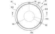
- the quartz crucible support device of Patent Document 1 includes, as shown in FIGS. 4A and 4B, a graphite crucible 91 supporting the quartz crucible 221 and a crucible support pedestal 92 made of graphite supporting the graphite crucible 91.
- the graphite crucible 91 is composed of a disk-shaped bottom portion 91A and other side portions 91B.
- the side portion 91B is composed of first, second and third divided graphite members 91C, 91D and 91E which are obtained by dividing the longitudinal division into three equal parts.
- the bottom of the graphite crucible 91 is provided with a recess 91 F in which the crucible support pedestal 92 is fitted.
- a separation suppressing member 93 is provided on the upper surface of each of the divided graphite members 91C, 91D, 91E to suppress the separation of the two from each other.
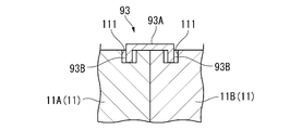
- the separation suppressing member 93 is provided at both ends of the rod-like connecting portion 93A and the connecting portion 93A, and is accommodated in the circular pin support holes 911 of the divided graphite members 91C, 91D, 91E.
- a cylindrical pin portion 93B is formed larger than the outer diameter of the pin portion 93 B, and the pin portion 93 B is configured to be relatively movable within the pin support hole 911.
- the silicon single crystal is grown, and after the growth, in order to replace the quartz crucible 221, the inside of the chamber is cooled to solidify the remaining solution of the silicon melt. At this solidification stage, the silicon melt solidifies in the expanded state.
- the quartz crucible 221 shrinks to return to its pre-expanded shape by cooling.
- the solidified material M1 is accommodated in the quartz crucible 221 in a more expanded state than in melting, at least the storage portion of the solidified material M1 can not return to the state before expansion.
- the divided graphite members 91C, 91D, 91E and the crucible support pedestals 92 also contract to return to their pre-expanded shape by cooling.
- the heel support pedestal 92 can return to its pre-inflated shape because there is no obstruction during contraction.
- each of the divided graphite members 91C, 91D, and 91E can not return to the state before expansion because the accommodation portion of the solidified material M1 in the quartz crucible 221 can not return to the state before expansion.
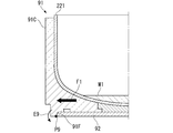
- An outward force F1 acts.
- the force F1 causes the upper ends of the divided graphite members 91C, 91D, 91E to be separated from each other with the contact portion P9 between the opening edge of the recess 91F of the graphite crucible 91 and the lower edge of the crucible support pedestal 92 as a rotation center.
- the moment E9 to rotate is generated.
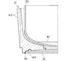
- the upper end side of each of the divided graphite members 91C, 91D, 91E is opened, and contacts the heater (not shown) provided on the outside of the graphite crucible 91, There is a risk of damaging the heater.
- the object of the present invention is to provide a crucible support pedestal capable of suppressing the opening of the upper end of the divided graphite member at the time of solidification of silicon melt, a quartz crucible support device provided with the support crucible, and silicon singlet using the quartz crucible support device. It is an object of the present invention to provide a method for producing crystals.
- the crucible support pedestal of the present invention is configured to be attachable to a single crystal pulling apparatus using the Czochralski method, and supports a plurality of divided graphite members obtained by vertically dividing a graphite crucible supporting a quartz crucible.
- a fitting recess into which the plurality of divided graphite members can be fitted, the opening edge of the fitting recess being in contact with the plurality of divided graphite members after the silicon single crystal is grown It is provided at a position higher than the surface of the solidified silicon melt remaining in the crucible, and the force acting on the plurality of divided graphite members as the silicon melt expands when solidified, than the contact portion. It is characterized in that it is configured to act at a low position.
- the crucible support pedestal of the present invention is configured to be attachable to a single crystal pulling apparatus using the Czochralski method, and supports a plurality of divided graphite members obtained by vertically dividing a graphite crucible supporting a quartz crucible.
- the fitting recess includes a fitting recess to which the plurality of divided graphite members can be fitted, the fitting recess having a depth of the fitting recess of A (mm), and the graphite crucible in the plurality of divided graphite members Solidification of silicon melt remaining in the quartz crucible after growth of silicon single crystal, B (mm), thickness of the center of the bottom of the quartz crucible, C (mm) Is set to satisfy the following expression (1), where D (mm) is the height of A> B + C + D (1)
- the crucible support pedestal of the present invention is configured to be attachable to a single crystal pulling apparatus using the Czochralski method, and supports a plurality of divided graphite members obtained by vertically dividing a graphite crucible supporting a quartz crucible.
- the fitting recess includes a fitting recess to which the plurality of divided graphite members can be fitted, the fitting recess having a depth of the fitting recess of A (mm), and the graphite crucible in the plurality of divided graphite members
- B (mm) The thickness of the position corresponding to the center of the bottom portion of B is defined as B (mm), and the following formula (2) is satisfied.
- the crucible support pedestal of the present invention is configured to be attachable to a single crystal pulling apparatus using the Czochralski method, and supports a plurality of divided graphite members obtained by vertically dividing a graphite crucible supporting a quartz crucible.
- the fitting recess includes a fitting recess to which the plurality of divided graphite members can be fitted, the fitting recess having a depth of the fitting recess of A (mm), and the graphite crucible in the plurality of divided graphite members
- the thickness of the position corresponding to the center of the bottom portion of B is defined as B (mm), and the following formula (3) is satisfied.
- the crucible support pedestal of the present invention is configured to be attachable to a single crystal pulling apparatus using the Czochralski method, and supports a plurality of divided graphite members obtained by vertically dividing a graphite crucible supporting a quartz crucible.
- the fitting recess includes a fitting recess to which the plurality of divided graphite members can be fitted, the fitting recess having a depth of the fitting recess of A (mm), and the graphite crucible in the plurality of divided graphite members
- B (mm) The thickness of the position corresponding to the center of the bottom portion of B is defined as B (mm), and the following formula (4) is satisfied.
- the crucible support pedestal of the present invention is configured to be attachable to a single crystal pulling apparatus using the Czochralski method, and supports a plurality of divided graphite members obtained by vertically dividing a graphite crucible supporting a quartz crucible.
- the fitting recess includes a fitting recess to which the plurality of divided graphite members can be fitted, the fitting recess having a depth of the fitting recess of A (mm), and the graphite crucible in the plurality of divided graphite members
- B (mm) The thickness of the position corresponding to the center of the bottom portion of B is defined as B (mm), and the following formula (5) is satisfied.
- the thickness at the center of the bottom of the quartz crucible (hereinafter sometimes referred to as "thickness of bottom of quartz crucible") is It is preferable that they are 6 mm or more and 15 mm or less.
- the height of the solidified product of the silicon melt at the time of production of a 150 mm silicon single crystal is generally 10 mm or more and 30 mm or less. “45 mm” on the right side of the equation (2) is the sum of 15 mm which is the maximum thickness of the bottom of the quartz crucible and 30 mm which is the maximum height of the solidified material.
- the thickness of the bottom of the quartz crucible is preferably 8 mm or more and 22 mm or less.
- the height of the solidified product of silicon melt at the time of production of 200 mm silicon single crystal is generally 15 mm or more and 40 mm or less.
- “62 mm” on the right side of the equation (3) is the sum of 22 mm which is the maximum value of the thickness of the bottom of the quartz crucible and 40 mm which is the maximum value of the height of the solidified material.
- the thickness of the bottom of the quartz crucible is preferably 10 mm or more and 25 mm or less.
- the height of the solidified product of the silicon melt at the time of production of a 300 mm silicon single crystal is generally 15 mm or more and 40 mm or less.
- “65 mm” on the right side of the equation (4) is the sum of 25 mm which is the maximum thickness of the bottom of the quartz crucible and 40 mm which is the maximum height of the solidified material.
- the thickness of the bottom of the quartz crucible is preferably 15 mm or more and 30 mm or less.
- the height of the solidified product of the silicon melt at the time of production of the 450 mm silicon single crystal is generally 20 mm or more and 80 mm or less.
- “110 mm” on the right side of the equation (5) is the sum of 30 mm which is the maximum value of the thickness of the bottom of the quartz crucible and 80 mm which is the maximum value of the height of the solidified material.
- the opening edge of the fitting recess has a contact portion with a plurality of divided graphite members It will be provided at a position higher than the surface of the solidified silicon melt remaining in the quartz crucible after the growth of the silicon single crystal. Therefore, force F1 acting on the divided graphite member by the influence of the solidified material as shown in FIG. 5A is generated below the contact portion between the opening edge of the fitting recess of the crucible support pedestal and the plurality of divided graphite members. It is possible to prevent the upper end of the graphite split member from opening.
- the quartz crucible supporting apparatus comprises a plurality of divided graphite members obtained by vertically dividing a graphite crucible supporting the quartz crucible, and the above-mentioned crucible supporting pedestal supporting the plurality of divided graphite members. It is characterized by
- the quartz crucible supporting apparatus comprises: a plurality of divided graphite members obtained by vertically dividing a graphite crucible supporting the quartz crucible; and the above-mentioned crucible supporting base for supporting the plurality of divided graphite members;
- the inner diameter of the previous graphite crucible is 452 mm to 462 mm, the B is 12 mm to 20 mm, the C is 6 mm to 15 mm, and the D is 10 mm to 30 mm.
- the quartz crucible supporting apparatus comprises: a plurality of divided graphite members obtained by vertically dividing a graphite crucible supporting the quartz crucible; and the above-mentioned crucible supporting base for supporting the plurality of divided graphite members;
- the inner diameter of the previous graphite crucible is 553 mm to 615 mm, the B is 15 mm to 35 mm, the C is 8 mm to 22 mm, and the D is 15 mm to 40 mm.
- the quartz crucible supporting apparatus comprises: a plurality of divided graphite members obtained by vertically dividing a graphite crucible supporting the quartz crucible; and the above-mentioned crucible supporting base for supporting the plurality of divided graphite members;
- the inner diameter of the previous graphite crucible is 803 mm or more and 823 mm or less, the B is 20 mm or more and 45 mm or less, the C is 10 mm or more and 25 mm or less, and the D is 15 mm or more and 40 mm or less.
- the quartz crucible supporting apparatus comprises: a plurality of divided graphite members obtained by vertically dividing a graphite crucible supporting the quartz crucible; and the above-mentioned crucible supporting base for supporting the plurality of divided graphite members;
- the inner diameter of the previous graphite crucible is 1001 mm or more and 1031 mm or less, the B is 25 mm or more and 55 mm or less, the C is 15 mm or more and 30 mm or less, and the D is 20 mm or more and 80 mm or less.
- the quartz crucible supporting apparatus comprises: a plurality of divided graphite members obtained by vertically dividing a graphite crucible supporting the quartz crucible; and the above-mentioned crucible supporting base for supporting the plurality of divided graphite members;
- the internal diameter of the previous graphite crucible is 452 mm or more and 462 mm or less, and the B is 12 mm or more and 20 mm or less.
- the quartz crucible supporting apparatus comprises: a plurality of divided graphite members obtained by vertically dividing a graphite crucible supporting the quartz crucible; and the above-mentioned crucible supporting base for supporting the plurality of divided graphite members;
- the inner diameter of the previous graphite crucible is 553 mm or more and 615 mm or less, and the B is 15 mm or more and 35 mm or less.
- the quartz crucible supporting apparatus comprises: a plurality of divided graphite members obtained by vertically dividing a graphite crucible supporting the quartz crucible; and the above-mentioned crucible supporting base for supporting the plurality of divided graphite members;
- the inner diameter of the previous graphite crucible is 803 mm or more and 823 mm or less, and the B is 20 mm or more and 45 mm or less.
- the quartz crucible supporting apparatus comprises: a plurality of divided graphite members obtained by vertically dividing a graphite crucible supporting the quartz crucible; and the above-mentioned crucible supporting base for supporting the plurality of divided graphite members;
- the inner diameter of the previous graphite crucible is 1001 mm or more and 1031 mm or less, and the B is 25 mm or more and 55 mm or less.
- the method for producing a silicon single crystal according to the present invention is a method for producing a silicon single crystal using a quartz crucible and the above-mentioned quartz crucible supporting device for supporting the quartz crucible, and the quartz after growing the silicon single crystal. Solidifying the silicon melt so that the surface of the solidified silicon melt remaining in the crucible is at a lower position than the contact portion between the opening edge of the fitting recess and the plurality of divided graphite members It is characterized by
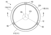
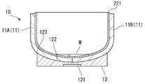
- FIG. 2 is a cross-sectional view taken along the line BB of FIG. 1A, showing the quartz crucible support device in the one embodiment.
- the quartz crucible supporting apparatus 10 supports a quartz crucible 221.
- the quartz crucible supporting apparatus 10 is a first, second and third divided graphite members 11A, 11B and 11C (hereinafter collectively referred to as "divided graphite members 11" obtained by dividing the graphite crucible into three longitudinally divided pieces.
- a pin support hole 111 into which the pin portion 93B of the separation suppressing member 93 is inserted is provided in the upper surface of the divided graphite member 11.
- the pin support hole 111 is formed such that a gap is provided between it and the pin portion 93B when the pin portion 93B is inserted.
- the crucible support pedestal 12 is formed of graphite and is circular in plan view.
- a support shaft fitting groove 121 into which the support shaft 25 is fitted is provided on one surface of the crucible support pedestal 12.
- the other surface of the crucible support pedestal 12 is provided with a fitting recess 122 in which the lower portion of the divided graphite member 11 can be fitted. As shown in FIG.
- the opening edge 123 of the fitting recess 122 has a depth (distance from the opening surface 124 of the fitting recess 122 to the center of the bottom) of the fitting recess 122 of A (mm), divided graphite
- the thickness of the position corresponding to the center of the bottom of the graphite crucible before division in the member 11 is B (mm)
- the thickness of the center of the bottom of the quartz crucible 221 is C (mm)
- solidified product height D the distance from the surface of the solidified product M1 to the center of the bottom of the quartz crucible 221
- Formula (1) of may be satisfy
- the upper limit of the depth A of the fitting recess 122 is preferably a value such that the opening edge 123 is at the same position as the upper end of the divided graphite member 11 or a position lower than the upper end.
- the contact portion P1 between the opening edge 123 of the fitting recess 122 and each of the divided graphite members 11A, 11B and 11C is made of silicon melt M after growth of silicon single crystal. It becomes a position higher than the surface of solidification thing M1.
- the crucible support pedestal 12 may be configured to satisfy the following equation (2) when the diameter of the silicon single crystal is 150 mm, or to satisfy the following equation (3) when the diameter is 200 mm. It may be configured, and may be configured to satisfy the following equation (4) if the diameter is 300 mm, or may be configured to satisfy the following equation (5) if the diameter is 450 mm: It may be A> B + 45 mm ... (2) A> B + 62 mm ... (3) A> B + 65 mm ... (4) A> B + 110 mm ... (5)
- the inner diameter of the graphite crucible in Table 1 is the maximum inner diameter of the graphite crucible, and when the graphite crucible has a straight barrel (a cylindrical portion having the same inner diameter at all positions in the height direction), it means the inner diameter of the straight barrel. .
- the amount of residual solution of the silicon melt M after the growth of the silicon single crystal is 1% to 10% of the initial charge amount of the silicon raw material.
- the solidified material height D in Table 1 is a value when the silicon melt M is solidified corresponding to 1% to 10% of the initial charge amount.
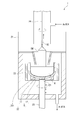
- the quartz crucible 221 is supported by the quartz crucible supporting apparatus 10 in the chamber 21 of the single crystal pulling apparatus 1 (hereinafter, the quartz crucible 221 and the quartz crucible supporting apparatus 10 are collectively referred to as “coffin 22” ), Charge the solid silicon raw material in the quartz crucible 221. By heating the crucible 22 with the heater 23, the silicon raw material in the crucible 22 is melted to generate the silicon melt M.
- the quartz crucible 221, the divided graphite member 11 and the crucible support pedestal 12 are expanded by heating.
- Each divided graphite member 11A, 11B, 11C is pushed outward by the expanded quartz crucible 221, and the pin portion 93B of the separation suppressing member 93 relatively moves within the pin support hole 111, and each divided graphite member until they contact 11A, 11B, 11C are spaced apart from one another.
- the silicon melt M After the formation of the silicon melt M, argon gas is introduced into the chamber 21 to maintain an inert atmosphere under reduced pressure, and the crucible 22 is rotated by driving the support shaft 25 to contact the seed crystal SC with the silicon melt M. Then, the silicon single crystal SM is grown by pulling up with the pulling cable 24.
- the inside of the chamber 21 is cooled to solidify the residual liquid of the silicon melt M in order to replace the quartz crucible 221.
- the silicon melt M solidifies in a more expanded state than at the time of melting.
- the quartz crucible 221 shrinks to return to the shape before expansion, but since the solidified material M1 is accommodated in the expanded state more than the molten state, at least the housing portion of the solidified material M1 returns to the state before expansion. I can not do it.
- the crucible support pedestal 12 can return to its pre-expanded shape because it has no obstacles during contraction. However, since each of the divided graphite members 11A, 11B, and 11C can not return to the state before expansion because the portion of the solidified product M1 in the quartz crucible 221 can be restored, as shown in FIG. An outward force F1 acts on the portion in contact with the contact. At this time, since the contact portion P1 is at a position higher than the surface of the solidified product M1 of the silicon melt M, the divided graphite members 11A, 11B, and 11C are rotated about the contact portion P1 by the force F1. A moment E1 is generated to rotate the upper ends in the direction in which they approach each other. The moment E1 prevents the upper end sides of the divided graphite members 11A, 11B, and 11C from being open, and can prevent the broken graphite members 11A, 11B, and 11C from damaging the heater 23.
- the divided support member may have a shape obtained by dividing a graphite crucible into two or four equal parts.
Landscapes
- Chemical & Material Sciences (AREA)
- Engineering & Computer Science (AREA)
- Crystallography & Structural Chemistry (AREA)
- Materials Engineering (AREA)
- Metallurgy (AREA)
- Organic Chemistry (AREA)
- Crystals, And After-Treatments Of Crystals (AREA)
Abstract
坩堝支持台座(12)は、分割黒鉛部材(11)が嵌合可能な嵌合凹部(122)を備え、嵌合凹部(122)の開口縁(123)は、分割黒鉛部材(11)との接触部(P1)が、シリコン単結晶の育成後に石英坩堝(221)に残っているシリコン融液の固化物(M1)の表面よりも高くなる位置に設けられ、シリコン融液の固化時の膨張に伴い分割黒鉛部材(11)に作用する力が、接触部(P1)よりも低い位置に作用するように構成されている。
Description
本発明は、坩堝支持台座、石英坩堝支持装置およびシリコン単結晶の製造方法に関する。
従来、チョクラルスキー法によるシリコン単結晶の製造に用いられ、石英坩堝を支持する石英坩堝支持装置が知られている(例えば、特許文献1参照)。
特許文献1の石英坩堝支持装置は、図4A,図4Bに示すように、石英坩堝221を支持する黒鉛坩堝91と、黒鉛坩堝91を支持する黒鉛製の坩堝支持台座92とを備えている。
黒鉛坩堝91は、円板状の底部91Aと、それ以外の側部91Bとから構成されている。側部91Bは、縦割りに3等分して得られる第1,第2,第3の分割黒鉛部材91C,91D,91Eから構成されている。
黒鉛坩堝91の底面には、坩堝支持台座92が嵌め込まれる凹部91Fが設けられている。
各分割黒鉛部材91C,91D,91Eの上面には、これらが互いに離間することを抑制する離間抑制部材93が設けられている。離間抑制部材93は、図4Cに示すように、棒状の連結部93Aと、この連結部93Aの両端に設けられ、各分割黒鉛部材91C,91D,91Eの円形のピン支持穴911に収容される円柱状のピン部93Bとを備えている。ピン支持穴911の内径は、ピン部93Bの外径よりも大きく形成されており、ピン部93Bが当該ピン支持穴911内で相対移動可能に構成されている。
特許文献1の石英坩堝支持装置は、図4A,図4Bに示すように、石英坩堝221を支持する黒鉛坩堝91と、黒鉛坩堝91を支持する黒鉛製の坩堝支持台座92とを備えている。
黒鉛坩堝91は、円板状の底部91Aと、それ以外の側部91Bとから構成されている。側部91Bは、縦割りに3等分して得られる第1,第2,第3の分割黒鉛部材91C,91D,91Eから構成されている。
黒鉛坩堝91の底面には、坩堝支持台座92が嵌め込まれる凹部91Fが設けられている。
各分割黒鉛部材91C,91D,91Eの上面には、これらが互いに離間することを抑制する離間抑制部材93が設けられている。離間抑制部材93は、図4Cに示すように、棒状の連結部93Aと、この連結部93Aの両端に設けられ、各分割黒鉛部材91C,91D,91Eの円形のピン支持穴911に収容される円柱状のピン部93Bとを備えている。ピン支持穴911の内径は、ピン部93Bの外径よりも大きく形成されており、ピン部93Bが当該ピン支持穴911内で相対移動可能に構成されている。
図4A,図4B,図4Cに示すような坩堝を用いてチョクラルスキー法によってシリコン単結晶を製造する場合、まず、石英坩堝221にシリコン原料をチャージし、ヒータで石英坩堝221および石英坩堝支持装置を加熱することでシリコン融液を生成する。このシリコン融液の生成段階において、石英坩堝221、黒鉛坩堝91および坩堝支持台座92は、加熱によって膨張する。石英坩堝221が膨張すると、石英坩堝221によって各分割黒鉛部材91C,91D,91Eが外側に押される。このとき、離間抑制部材93のピン部93Bがピン支持穴911内で相対移動し、これらが接触するまで、各分割黒鉛部材91C,91D,91Eは互いに離間する。
シリコン融液の生成後、シリコン単結晶の育成を行い、この育成後、石英坩堝221を交換するために、チャンバ内を冷却してシリコン融液の残液を固化させる。
この固化段階において、シリコン融液は、膨張した状態で固化する。
この固化段階において、シリコン融液は、膨張した状態で固化する。
一方、石英坩堝221は、冷却によって膨張前の形状に戻ろうと収縮する。しかし、図5Aに示すように、石英坩堝221には溶融時よりも膨張した状態で固化物M1が収容されているため、少なくとも固化物M1の収容部分が膨張前の状態に戻ることができない。
各分割黒鉛部材91C,91D,91Eおよび坩堝支持台座92も、冷却によって膨張前の形状に戻ろうと収縮する。
坩堝支持台座92は、収縮に際し障害がないため、膨張前の形状に戻ることができる。
一方、各分割黒鉛部材91C,91D,91Eは、石英坩堝221における固化物M1の収容部分が膨張前の状態に戻ることができないため、収縮しようとすると、当該収容部分と接触している部分に外側への力F1が作用する。この力F1によって、黒鉛坩堝91の凹部91Fの開口縁と坩堝支持台座92の下端縁との接触部P9を回動中心にして、各分割黒鉛部材91C,91D,91Eの上端を互いに離間する方向へ回転させるモーメントE9が発生する。このモーメントE9によって、図5Bに示すように、各分割黒鉛部材91C,91D,91Eの上端側が開いた状態となってしまい、黒鉛坩堝91の外側に設けられた図示しないヒータに接触して、当該ヒータを破損してしまうおそれがある。
坩堝支持台座92は、収縮に際し障害がないため、膨張前の形状に戻ることができる。
一方、各分割黒鉛部材91C,91D,91Eは、石英坩堝221における固化物M1の収容部分が膨張前の状態に戻ることができないため、収縮しようとすると、当該収容部分と接触している部分に外側への力F1が作用する。この力F1によって、黒鉛坩堝91の凹部91Fの開口縁と坩堝支持台座92の下端縁との接触部P9を回動中心にして、各分割黒鉛部材91C,91D,91Eの上端を互いに離間する方向へ回転させるモーメントE9が発生する。このモーメントE9によって、図5Bに示すように、各分割黒鉛部材91C,91D,91Eの上端側が開いた状態となってしまい、黒鉛坩堝91の外側に設けられた図示しないヒータに接触して、当該ヒータを破損してしまうおそれがある。
本発明の目的は、シリコン融液の固化時における分割黒鉛部材上端の開きを抑制可能な坩堝支持台座、当該支持坩堝を備えた石英坩堝支持装置、および、当該石英坩堝支持装置を用いたシリコン単結晶の製造方法を提供することにある。
本発明の坩堝支持台座は、チョクラルスキー法を用いる単結晶引き上げ装置に取り付け可能に構成され、石英坩堝を支持する黒鉛坩堝を縦割りにして得られる複数の分割黒鉛部材を支持する坩堝支持台座であって、前記複数の分割黒鉛部材が嵌合可能な嵌合凹部を備え、前記嵌合凹部の開口縁は、前記複数の分割黒鉛部材との接触部が、シリコン単結晶の育成後に前記石英坩堝に残っているシリコン融液の固化物の表面よりも高くなる位置に設けられ、前記シリコン融液の固化時の膨張に伴い前記複数の分割黒鉛部材に作用する力が、前記接触部よりも低い位置に作用するように構成されていることを特徴とする。
本発明によれば、図5Aに示すような融液時よりも膨張した固化物の影響によって分割黒鉛部材に作用する力F1を、坩堝支持台座の嵌合凹部の開口縁と複数の分割黒鉛部材との接触部よりも下側に発生させることができる。したがって、上記接触部を回動中心にして、複数の分割黒鉛部材を互いに離間する方向へ回転させるモーメントが発生することを抑制でき、黒鉛分割部材の上端が開くことを抑制できる。
本発明の坩堝支持台座は、チョクラルスキー法を用いる単結晶引き上げ装置に取り付け可能に構成され、石英坩堝を支持する黒鉛坩堝を縦割りにして得られる複数の分割黒鉛部材を支持する坩堝支持台座であって、前記複数の分割黒鉛部材が嵌合可能な嵌合凹部を備え、前記嵌合凹部は、当該嵌合凹部の深さをA(mm)、前記複数の分割黒鉛部材における前記黒鉛坩堝の底部中央に対応する位置の肉厚をB(mm)、前記石英坩堝における底部中央の肉厚をC(mm)、シリコン単結晶の育成後に前記石英坩堝に残っているシリコン融液の固化物の高さをD(mm)として、以下の式(1)を満たすように構成されていることを特徴とする。
A>B+C+D … (1)
A>B+C+D … (1)
本発明の坩堝支持台座は、チョクラルスキー法を用いる単結晶引き上げ装置に取り付け可能に構成され、石英坩堝を支持する黒鉛坩堝を縦割りにして得られる複数の分割黒鉛部材を支持する坩堝支持台座であって、前記複数の分割黒鉛部材が嵌合可能な嵌合凹部を備え、前記嵌合凹部は、当該嵌合凹部の深さをA(mm)、前記複数の分割黒鉛部材における前記黒鉛坩堝の底部中央に対応する位置の肉厚をB(mm)として、以下の式(2)を満たすように構成されていることを特徴とする。
A>B+45mm … (2)
A>B+45mm … (2)
本発明の坩堝支持台座は、チョクラルスキー法を用いる単結晶引き上げ装置に取り付け可能に構成され、石英坩堝を支持する黒鉛坩堝を縦割りにして得られる複数の分割黒鉛部材を支持する坩堝支持台座であって、前記複数の分割黒鉛部材が嵌合可能な嵌合凹部を備え、前記嵌合凹部は、当該嵌合凹部の深さをA(mm)、前記複数の分割黒鉛部材における前記黒鉛坩堝の底部中央に対応する位置の肉厚をB(mm)として、以下の式(3)を満たすように構成されていることを特徴とする。
A>B+62mm … (3)
A>B+62mm … (3)
本発明の坩堝支持台座は、チョクラルスキー法を用いる単結晶引き上げ装置に取り付け可能に構成され、石英坩堝を支持する黒鉛坩堝を縦割りにして得られる複数の分割黒鉛部材を支持する坩堝支持台座であって、前記複数の分割黒鉛部材が嵌合可能な嵌合凹部を備え、前記嵌合凹部は、当該嵌合凹部の深さをA(mm)、前記複数の分割黒鉛部材における前記黒鉛坩堝の底部中央に対応する位置の肉厚をB(mm)として、以下の式(4)を満たすように構成されていることを特徴とする。
A>B+65mm … (4)
A>B+65mm … (4)
本発明の坩堝支持台座は、チョクラルスキー法を用いる単結晶引き上げ装置に取り付け可能に構成され、石英坩堝を支持する黒鉛坩堝を縦割りにして得られる複数の分割黒鉛部材を支持する坩堝支持台座であって、前記複数の分割黒鉛部材が嵌合可能な嵌合凹部を備え、前記嵌合凹部は、当該嵌合凹部の深さをA(mm)、前記複数の分割黒鉛部材における前記黒鉛坩堝の底部中央に対応する位置の肉厚をB(mm)として、以下の式(5)を満たすように構成されていることを特徴とする。
A>B+110mm … (5)
A>B+110mm … (5)
式(2)を満たす坩堝支持台座を、例えば、直径が150mmのシリコン単結晶の製造に用いる場合、石英坩堝における底部中央の肉厚(以下「石英坩堝底部の肉厚」という場合がある)は6mm以上15mm以下であることが好ましい。150mmのシリコン単結晶の製造時におけるシリコン融液の固化物の高さは、10mm以上30mm以下となるのが一般的である。式(2)の右辺の「45mm」は、石英坩堝底部の肉厚の最大値である15mmと、固化物の高さの最大値である30mmとの和である。
式(3)を満たす坩堝支持台座を、例えば、直径が200mmのシリコン単結晶の製造に用いる場合、石英坩堝底部の肉厚は8mm以上22mm以下であることが好ましい。200mmのシリコン単結晶の製造時におけるシリコン融液の固化物の高さは、15mm以上40mm以下となるのが一般的である。式(3)の右辺の「62mm」は、石英坩堝底部の肉厚の最大値である22mmと、固化物の高さの最大値である40mmとの和である。
式(4)を満たす坩堝支持台座を、例えば、直径が300mmのシリコン単結晶の製造に用いる場合、石英坩堝底部の肉厚は10mm以上25mm以下であることが好ましい。300mmのシリコン単結晶の製造時におけるシリコン融液の固化物の高さは、15mm以上40mm以下となるのが一般的である。式(4)の右辺の「65mm」は、石英坩堝底部の肉厚の最大値である25mmと、固化物の高さの最大値である40mmとの和である。
式(5)を満たす坩堝支持台座を、例えば、直径が450mmのシリコン単結晶の製造に用いる場合、石英坩堝底部の肉厚は15mm以上30mm以下であることが好ましい。450mmのシリコン単結晶の製造時におけるシリコン融液の固化物の高さは、20mm以上80mm以下となるのが一般的である。式(5)の右辺の「110mm」は、石英坩堝底部の肉厚の最大値である30mmと、固化物の高さの最大値である80mmとの和である。
本発明の式(1),(2),(3),(4),(5)を満たす坩堝支持台座によれば、嵌合凹部の開口縁は、複数の分割黒鉛部材との接触部が、シリコン単結晶の育成後に石英坩堝に残っているシリコン融液の固化物の表面よりも高くなる位置に設けられることになる。したがって、図5Aに示すような固化物の影響によって分割黒鉛部材に作用する力F1を、坩堝支持台座の嵌合凹部の開口縁と複数の分割黒鉛部材との接触部よりも下側に発生させることができ、黒鉛分割部材の上端が開くことを抑制できる。
本発明の石英坩堝支持装置は、石英坩堝を支持する黒鉛坩堝を縦割りにして得られる複数の分割黒鉛部材と、前記複数の分割黒鉛部材を支持する上述の坩堝支持台座とを備えていることを特徴とする。
本発明の石英坩堝支持装置は、石英坩堝を支持する黒鉛坩堝を縦割りにして得られる複数の分割黒鉛部材と、前記複数の分割黒鉛部材を支持する上述の坩堝支持台座とを備え、縦割り前の前記黒鉛坩堝の内径が452mm以上462mm以下であり、前記Bが12mm以上20mm以下、前記Cが6mm以上15mm以下、前記Dが10mm以上30mm以下であることを特徴とする。
本発明の石英坩堝支持装置は、石英坩堝を支持する黒鉛坩堝を縦割りにして得られる複数の分割黒鉛部材と、前記複数の分割黒鉛部材を支持する上述の坩堝支持台座とを備え、縦割り前の前記黒鉛坩堝の内径が553mm以上615mm以下であり、前記Bが15mm以上35mm以下、前記Cが8mm以上22mm以下、前記Dが15mm以上40mm以下であることを特徴とする。
本発明の石英坩堝支持装置は、石英坩堝を支持する黒鉛坩堝を縦割りにして得られる複数の分割黒鉛部材と、前記複数の分割黒鉛部材を支持する上述の坩堝支持台座とを備え、縦割り前の前記黒鉛坩堝の内径が803mm以上823mm以下であり、前記Bが20mm以上45mm以下、前記Cが10mm以上25mm以下、前記Dが15mm以上40mm以下であることを特徴とする。
本発明の石英坩堝支持装置は、石英坩堝を支持する黒鉛坩堝を縦割りにして得られる複数の分割黒鉛部材と、前記複数の分割黒鉛部材を支持する上述の坩堝支持台座とを備え、縦割り前の前記黒鉛坩堝の内径が1001mm以上1031mm以下であり、前記Bが25mm以上55mm以下、前記Cが15mm以上30mm以下、前記Dが20mm以上80mm以下であることを特徴とする。
本発明の石英坩堝支持装置は、石英坩堝を支持する黒鉛坩堝を縦割りにして得られる複数の分割黒鉛部材と、前記複数の分割黒鉛部材を支持する上述の坩堝支持台座とを備え、縦割り前の前記黒鉛坩堝の内径が452mm以上462mm以下であり、前記Bが12mm以上20mm以下であることを特徴とする。
本発明の石英坩堝支持装置は、石英坩堝を支持する黒鉛坩堝を縦割りにして得られる複数の分割黒鉛部材と、前記複数の分割黒鉛部材を支持する上述の坩堝支持台座とを備え、縦割り前の前記黒鉛坩堝の内径が553mm以上615mm以下であり、前記Bが15mm以上35mm以下であることを特徴とする。
本発明の石英坩堝支持装置は、石英坩堝を支持する黒鉛坩堝を縦割りにして得られる複数の分割黒鉛部材と、前記複数の分割黒鉛部材を支持する上述の坩堝支持台座とを備え、縦割り前の前記黒鉛坩堝の内径が803mm以上823mm以下であり、前記Bが20mm以上45mm以下であることを特徴とする。
本発明の石英坩堝支持装置は、石英坩堝を支持する黒鉛坩堝を縦割りにして得られる複数の分割黒鉛部材と、前記複数の分割黒鉛部材を支持する上述の坩堝支持台座とを備え、縦割り前の前記黒鉛坩堝の内径が1001mm以上1031mm以下であり、前記Bが25mm以上55mm以下であることを特徴とする。
本発明のシリコン単結晶の製造方法は、石英坩堝と、前記石英坩堝を支持する上述の石英坩堝支持装置とを用いたシリコン単結晶の製造方法であって、前記シリコン単結晶の育成後に前記石英坩堝に残っているシリコン融液の固化物の表面が、前記嵌合凹部の開口縁と前記複数の分割黒鉛部材との接触部よりも低い位置となるように、前記シリコン融液を固化することを特徴とする。
本発明によれば、シリコン融液の固化時における分割黒鉛部材上端の開きが抑制されるため、ヒータの破損を抑制できる。
[実施形態]
以下、本発明の一実施形態について図面を参照して説明する。
〔石英坩堝支持装置の構成〕
図1A,図1Bに示すように、石英坩堝支持装置10は、石英坩堝221を支持する。石英坩堝支持装置10は、黒鉛坩堝を縦割りに3等分して得られる第1,第2,第3の分割黒鉛部材11A,11B,11C(以下、まとめて「分割黒鉛部材11」という場合がある)と、分割黒鉛部材11を支持する坩堝支持台座12と、各分割黒鉛部材11A,11B,11Cが石英坩堝221の中心CAから離れかつ互いに離間する方向に移動することを抑制する離間抑制部材93とを備えている。
以下、本発明の一実施形態について図面を参照して説明する。
〔石英坩堝支持装置の構成〕
図1A,図1Bに示すように、石英坩堝支持装置10は、石英坩堝221を支持する。石英坩堝支持装置10は、黒鉛坩堝を縦割りに3等分して得られる第1,第2,第3の分割黒鉛部材11A,11B,11C(以下、まとめて「分割黒鉛部材11」という場合がある)と、分割黒鉛部材11を支持する坩堝支持台座12と、各分割黒鉛部材11A,11B,11Cが石英坩堝221の中心CAから離れかつ互いに離間する方向に移動することを抑制する離間抑制部材93とを備えている。
分割黒鉛部材11の上面には、離間抑制部材93のピン部93Bが挿入されるピン支持穴111が設けられている。ピン支持穴111は、ピン部93Bが挿入されたときに、当該ピン部93Bとの間に隙間が設けられるように形成されている。
坩堝支持台座12は、黒鉛によって平面視円形に形成されている。坩堝支持台座12の一方の面には、支持軸25が嵌め込まれる支持軸嵌合溝121が設けられている。
坩堝支持台座12の他方の面には、分割黒鉛部材11の下部が嵌合可能な嵌合凹部122が設けられている。この嵌合凹部122の開口縁123は、図2に示すように、当該嵌合凹部122の深さ(嵌合凹部122の開口面124から底部中央までの距離)をA(mm)、分割黒鉛部材11における分割前の黒鉛坩堝の底部中央に対応する位置の肉厚をB(mm)、石英坩堝221における底部中央の肉厚をC(mm)、シリコン単結晶の育成後に石英坩堝221に残っているシリコン融液Mの固化物M1の高さ(固化物M1の表面から石英坩堝221の底部中央までの距離)をD(以下、「固化物高さD」という)(mm)として、以下の式(1)を満たすように構成されている。
嵌合凹部122の深さAの上限値は、開口縁123が分割黒鉛部材11の上端と同じ位置あるいは当該上端よりも低い位置となるような値であることが好ましい。
A>B+C+D … (1)
坩堝支持台座12の他方の面には、分割黒鉛部材11の下部が嵌合可能な嵌合凹部122が設けられている。この嵌合凹部122の開口縁123は、図2に示すように、当該嵌合凹部122の深さ(嵌合凹部122の開口面124から底部中央までの距離)をA(mm)、分割黒鉛部材11における分割前の黒鉛坩堝の底部中央に対応する位置の肉厚をB(mm)、石英坩堝221における底部中央の肉厚をC(mm)、シリコン単結晶の育成後に石英坩堝221に残っているシリコン融液Mの固化物M1の高さ(固化物M1の表面から石英坩堝221の底部中央までの距離)をD(以下、「固化物高さD」という)(mm)として、以下の式(1)を満たすように構成されている。
嵌合凹部122の深さAの上限値は、開口縁123が分割黒鉛部材11の上端と同じ位置あるいは当該上端よりも低い位置となるような値であることが好ましい。
A>B+C+D … (1)
この式(1)を満たす構成にすることによって、嵌合凹部122の開口縁123と各分割黒鉛部材11A,11B,11Cとの接触部P1は、シリコン単結晶の育成後におけるシリコン融液Mの固化物M1の表面よりも高い位置になる。
外周研削後の直径が所定値のシリコン単結晶を育成する場合において、分割前の黒鉛坩堝の内径、黒鉛坩堝の底部中央の肉厚B、石英坩堝221の底部中央の肉厚C、シリコン融液の固化物高さDは、以下の表1に示す範囲であることが好ましい。
坩堝支持台座12は、シリコン単結晶の直径が150mmの場合、以下の式(2)を満たすように構成されていてもよいし、直径が200mmの場合、以下の式(3)を満たすように構成されていてもよいし、直径が300mmの場合、以下の式(4)を満たすように構成されていてもよいし、直径が450mmの場合、以下の式(5)を満たすように構成されていてもよい。
A>B+45mm … (2)
A>B+62mm … (3)
A>B+65mm … (4)
A>B+110mm … (5)
坩堝支持台座12は、シリコン単結晶の直径が150mmの場合、以下の式(2)を満たすように構成されていてもよいし、直径が200mmの場合、以下の式(3)を満たすように構成されていてもよいし、直径が300mmの場合、以下の式(4)を満たすように構成されていてもよいし、直径が450mmの場合、以下の式(5)を満たすように構成されていてもよい。
A>B+45mm … (2)
A>B+62mm … (3)
A>B+65mm … (4)
A>B+110mm … (5)
表1における黒鉛坩堝の内径は、黒鉛坩堝の最大内径であり、黒鉛坩堝が直胴部(高さ方向の全ての位置で内径が同じ円筒部)を有する場合、直胴部の内径を意味する。
シリコン単結晶の育成後におけるシリコン融液Mの残液量は、シリコン原料の初期チャージ量の1%から10%である。表1における固化物高さDは、上記初期チャージ量の1%から10%に相当するシリコン融液Mが固化したときの値である。
シリコン単結晶の育成後におけるシリコン融液Mの残液量は、シリコン原料の初期チャージ量の1%から10%である。表1における固化物高さDは、上記初期チャージ量の1%から10%に相当するシリコン融液Mが固化したときの値である。

〔シリコン単結晶の製造方法〕
上記石英坩堝支持装置10を用いたチョクラルスキー法によるシリコン単結晶の製造方法について説明する。
上記石英坩堝支持装置10を用いたチョクラルスキー法によるシリコン単結晶の製造方法について説明する。
図3に示すように、単結晶引き上げ装置1のチャンバ21内において石英坩堝221を石英坩堝支持装置10で支持させ(以下、石英坩堝221および石英坩堝支持装置10をまとめて「坩堝22」という場合がある)、石英坩堝221内に固体のシリコン原料をチャージする。ヒータ23で坩堝22を加熱することで、当該坩堝22内のシリコン原料を融解させ、シリコン融液Mを生成する。
シリコン融液Mが生成されると、石英坩堝221、分割黒鉛部材11および坩堝支持台座12が加熱によって膨張する。膨張した石英坩堝221によって各分割黒鉛部材11A,11B,11Cが外側に押され、離間抑制部材93のピン部93Bがピン支持穴111内で相対移動し、これらが接触するまで、各分割黒鉛部材11A,11B,11Cは互いに離間する。
シリコン融液Mの生成後、チャンバ21にアルゴンガスを導入して減圧下の不活性雰囲気に維持し、支持軸25の駆動によって坩堝22を回転させつ、シリコン融液Mに種結晶SCを接触させた後に、引き上げケーブル24によって引き上げることで、シリコン単結晶SMを育成する。
シリコン単結晶SMの育成後、石英坩堝221を交換するために、チャンバ21内を冷却してシリコン融液Mの残液を固化させる。
この際、上述したように、シリコン融液Mは、溶融時よりも膨張した状態で固化する。
一方、石英坩堝221は、膨張前の形状に戻ろうと収縮するが、溶融時よりも膨張した状態で固化物M1が収容されているため、少なくとも固化物M1の収容部分が膨張前の状態に戻ることができない。
この際、上述したように、シリコン融液Mは、溶融時よりも膨張した状態で固化する。
一方、石英坩堝221は、膨張前の形状に戻ろうと収縮するが、溶融時よりも膨張した状態で固化物M1が収容されているため、少なくとも固化物M1の収容部分が膨張前の状態に戻ることができない。
坩堝支持台座12は、収縮に際し障害がないため、膨張前の形状に戻ることができる。
しかし、各分割黒鉛部材11A,11B,11Cは、石英坩堝221における固化物M1の収容部分が膨張前の状態に戻ることができないため、図2に示すように、収縮しようとすると、当該収容部分と接触している部分に外側への力F1が作用する。このとき、接触部P1がシリコン融液Mの固化物M1の表面よりも高い位置にあるため、力F1によって、当該接触部P1を回動中心にして、各分割黒鉛部材11A,11B,11Cの上端が互いに接近する方向へ回転させるモーメントE1が発生する。このモーメントE1によって、各分割黒鉛部材11A,11B,11Cの上端側が開いた状態となることが抑制され、各分割黒鉛部材11A,11B,11Cがヒータ23を破損することを抑制できる。
しかし、各分割黒鉛部材11A,11B,11Cは、石英坩堝221における固化物M1の収容部分が膨張前の状態に戻ることができないため、図2に示すように、収縮しようとすると、当該収容部分と接触している部分に外側への力F1が作用する。このとき、接触部P1がシリコン融液Mの固化物M1の表面よりも高い位置にあるため、力F1によって、当該接触部P1を回動中心にして、各分割黒鉛部材11A,11B,11Cの上端が互いに接近する方向へ回転させるモーメントE1が発生する。このモーメントE1によって、各分割黒鉛部材11A,11B,11Cの上端側が開いた状態となることが抑制され、各分割黒鉛部材11A,11B,11Cがヒータ23を破損することを抑制できる。
[変形例]
本発明は上記実施形態にのみ限定されるものではなく、本発明の要旨を逸脱しない範囲内において種々の改良ならびに設計の変更などが可能である。
本発明は上記実施形態にのみ限定されるものではなく、本発明の要旨を逸脱しない範囲内において種々の改良ならびに設計の変更などが可能である。
例えば、分割支持部材は、黒鉛坩堝を縦割りに2等分あるいは4等分して得られる形状であってもよい。
1…単結晶引き上げ装置、10…石英坩堝支持装置、11…分割黒鉛部材、12…坩堝支持台座、122…嵌合凹部、123…開口縁、221…石英坩堝、M…シリコン融液、M1…固化物、P1…接触部、SM…シリコン単結晶。
Claims (16)
- チョクラルスキー法を用いる単結晶引き上げ装置に取り付け可能に構成され、石英坩堝を支持する黒鉛坩堝を縦割りにして得られる複数の分割黒鉛部材を支持する坩堝支持台座であって、
前記複数の分割黒鉛部材が嵌合可能な嵌合凹部を備え、
前記嵌合凹部の開口縁は、前記複数の分割黒鉛部材との接触部が、シリコン単結晶の育成後に前記石英坩堝に残っているシリコン融液の固化物の表面よりも高くなる位置に設けられ、前記シリコン融液の固化時の膨張に伴い前記複数の分割黒鉛部材に作用する力が、前記接触部よりも低い位置に作用するように構成されていることを特徴とする坩堝支持台座。 - チョクラルスキー法を用いる単結晶引き上げ装置に取り付け可能に構成され、石英坩堝を支持する黒鉛坩堝を縦割りにして得られる複数の分割黒鉛部材を支持する坩堝支持台座であって、
前記複数の分割黒鉛部材が嵌合可能な嵌合凹部を備え、
前記嵌合凹部は、
当該嵌合凹部の深さをA(mm)、
前記複数の分割黒鉛部材における前記黒鉛坩堝の底部中央に対応する位置の肉厚をB(mm)、
前記石英坩堝における底部中央の肉厚をC(mm)、
シリコン単結晶の育成後に前記石英坩堝に残っているシリコン融液の固化物の高さをD(mm)として、以下の式(1)を満たすように構成されていることを特徴とする坩堝支持台座。
A>B+C+D … (1) - チョクラルスキー法を用いる単結晶引き上げ装置に取り付け可能に構成され、石英坩堝を支持する黒鉛坩堝を縦割りにして得られる複数の分割黒鉛部材を支持する坩堝支持台座であって、
前記複数の分割黒鉛部材が嵌合可能な嵌合凹部を備え、
前記嵌合凹部は、
当該嵌合凹部の深さをA(mm)、
前記複数の分割黒鉛部材における前記黒鉛坩堝の底部中央に対応する位置の肉厚をB(mm)として、以下の式(2)を満たすように構成されていることを特徴とする坩堝支持台座。
A>B+45mm … (2) - チョクラルスキー法を用いる単結晶引き上げ装置に取り付け可能に構成され、石英坩堝を支持する黒鉛坩堝を縦割りにして得られる複数の分割黒鉛部材を支持する坩堝支持台座であって、
前記複数の分割黒鉛部材が嵌合可能な嵌合凹部を備え、
前記嵌合凹部は、
当該嵌合凹部の深さをA(mm)、
前記複数の分割黒鉛部材における前記黒鉛坩堝の底部中央に対応する位置の肉厚をB(mm)として、以下の式(3)を満たすように構成されていることを特徴とする坩堝支持台座。
A>B+62mm … (3) - チョクラルスキー法を用いる単結晶引き上げ装置に取り付け可能に構成され、石英坩堝を支持する黒鉛坩堝を縦割りにして得られる複数の分割黒鉛部材を支持する坩堝支持台座であって、
前記複数の分割黒鉛部材が嵌合可能な嵌合凹部を備え、
前記嵌合凹部は、
当該嵌合凹部の深さをA(mm)、
前記複数の分割黒鉛部材における前記黒鉛坩堝の底部中央に対応する位置の肉厚をB(mm)として、以下の式(4)を満たすように構成されていることを特徴とする坩堝支持台座。
A>B+65mm … (4) - チョクラルスキー法を用いる単結晶引き上げ装置に取り付け可能に構成され、石英坩堝を支持する黒鉛坩堝を縦割りにして得られる複数の分割黒鉛部材を支持する坩堝支持台座であって、
前記複数の分割黒鉛部材が嵌合可能な嵌合凹部を備え、
前記嵌合凹部は、
当該嵌合凹部の深さをA(mm)、
前記複数の分割黒鉛部材における前記黒鉛坩堝の底部中央に対応する位置の肉厚をB(mm)として、以下の式(5)を満たすように構成されていることを特徴とする坩堝支持台座。
A>B+110mm … (5) - 石英坩堝を支持する黒鉛坩堝を縦割りにして得られる複数の分割黒鉛部材と、
前記複数の分割黒鉛部材を支持する請求項1から請求項6のいずれか一項に記載の坩堝支持台座とを備えていることを特徴とする石英坩堝支持装置。 - 石英坩堝を支持する黒鉛坩堝を縦割りにして得られる複数の分割黒鉛部材と、
前記複数の分割黒鉛部材を支持する請求項2に記載の坩堝支持台座とを備え、
縦割り前の前記黒鉛坩堝の内径が452mm以上462mm以下であり、
前記Bが12mm以上20mm以下、前記Cが6mm以上15mm以下、前記Dが10mm以上30mm以下であることを特徴とする石英坩堝支持装置。 - 石英坩堝を支持する黒鉛坩堝を縦割りにして得られる複数の分割黒鉛部材と、
前記複数の分割黒鉛部材を支持する請求項2に記載の坩堝支持台座とを備え、
縦割り前の前記黒鉛坩堝の内径が553mm以上615mm以下であり、
前記Bが15mm以上35mm以下、前記Cが8mm以上22mm以下、前記Dが15mm以上40mm以下であることを特徴とする石英坩堝支持装置。 - 石英坩堝を支持する黒鉛坩堝を縦割りにして得られる複数の分割黒鉛部材と、
前記複数の分割黒鉛部材を支持する請求項2に記載の坩堝支持台座とを備え、
縦割り前の前記黒鉛坩堝の内径が803mm以上823mm以下であり、
前記Bが20mm以上45mm以下、前記Cが10mm以上25mm以下、前記Dが15mm以上40mm以下であることを特徴とする石英坩堝支持装置。 - 石英坩堝を支持する黒鉛坩堝を縦割りにして得られる複数の分割黒鉛部材と、
前記複数の分割黒鉛部材を支持する請求項2に記載の坩堝支持台座とを備え、
縦割り前の前記黒鉛坩堝の内径が1001mm以上1031mm以下であり、
前記Bが25mm以上55mm以下、前記Cが15mm以上30mm以下、前記Dが20mm以上80mm以下であることを特徴とする石英坩堝支持装置。 - 石英坩堝を支持する黒鉛坩堝を縦割りにして得られる複数の分割黒鉛部材と、
前記複数の分割黒鉛部材を支持する請求項3に記載の坩堝支持台座とを備え、
縦割り前の前記黒鉛坩堝の内径が452mm以上462mm以下であり、
前記Bが12mm以上20mm以下であることを特徴とする石英坩堝支持装置。 - 石英坩堝を支持する黒鉛坩堝を縦割りにして得られる複数の分割黒鉛部材と、
前記複数の分割黒鉛部材を支持する請求項4に記載の坩堝支持台座とを備え、
縦割り前の前記黒鉛坩堝の内径が553mm以上615mm以下であり、
前記Bが15mm以上35mm以下であることを特徴とする石英坩堝支持装置。 - 石英坩堝を支持する黒鉛坩堝を縦割りにして得られる複数の分割黒鉛部材と、
前記複数の分割黒鉛部材を支持する請求項5に記載の坩堝支持台座とを備え、
縦割り前の前記黒鉛坩堝の内径が803mm以上823mm以下であり、
前記Bが20mm以上45mm以下であることを特徴とする石英坩堝支持装置。 - 石英坩堝を支持する黒鉛坩堝を縦割りにして得られる複数の分割黒鉛部材と、
前記複数の分割黒鉛部材を支持する請求項6に記載の坩堝支持台座とを備え、
縦割り前の前記黒鉛坩堝の内径が1001mm以上1031mm以下であり、
前記Bが25mm以上55mm以下であることを特徴とする石英坩堝支持装置。 - 石英坩堝と、
前記石英坩堝を支持する請求項7から請求項15のいずれか一項に記載の石英坩堝支持装置とを用いたシリコン単結晶の製造方法であって、
前記シリコン単結晶の育成後に前記石英坩堝に残っているシリコン融液の固化物の表面が、前記嵌合凹部の開口縁と前記複数の分割黒鉛部材との接触部よりも低い位置となるように、前記シリコン融液を固化することを特徴とするシリコン単結晶の製造方法。
Priority Applications (3)
| Application Number | Priority Date | Filing Date | Title |
|---|---|---|---|
| US16/649,282 US11598019B2 (en) | 2017-09-29 | 2018-05-31 | Crucible-supporting pedestal, quartz crucible-supporting device, and method for producing silicon single crystal |
| KR1020207009689A KR102307529B1 (ko) | 2017-09-29 | 2018-05-31 | 도가니 지지 대좌, 석영 도가니 지지 장치 및 실리콘 단결정의 제조 방법 |
| CN201880062777.7A CN111373080B (zh) | 2017-09-29 | 2018-05-31 | 坩埚支承底座、石英坩埚支承装置及单晶硅的制造方法 |
Applications Claiming Priority (2)
| Application Number | Priority Date | Filing Date | Title |
|---|---|---|---|
| JP2017191553A JP6743797B2 (ja) | 2017-09-29 | 2017-09-29 | 坩堝支持台座、石英坩堝支持装置およびシリコン単結晶の製造方法 |
| JP2017-191553 | 2017-09-29 |
Publications (1)
| Publication Number | Publication Date |
|---|---|
| WO2019064697A1 true WO2019064697A1 (ja) | 2019-04-04 |
Family
ID=65901165
Family Applications (1)
| Application Number | Title | Priority Date | Filing Date |
|---|---|---|---|
| PCT/JP2018/021026 Ceased WO2019064697A1 (ja) | 2017-09-29 | 2018-05-31 | 坩堝支持台座、石英坩堝支持装置およびシリコン単結晶の製造方法 |
Country Status (6)
| Country | Link |
|---|---|
| US (1) | US11598019B2 (ja) |
| JP (1) | JP6743797B2 (ja) |
| KR (1) | KR102307529B1 (ja) |
| CN (1) | CN111373080B (ja) |
| TW (1) | TWI675130B (ja) |
| WO (1) | WO2019064697A1 (ja) |
Families Citing this family (1)
| Publication number | Priority date | Publication date | Assignee | Title |
|---|---|---|---|---|
| CN116397318B (zh) * | 2023-06-09 | 2023-08-18 | 苏州晨晖智能设备有限公司 | 一种单晶坩埚装载装置 |
Citations (6)
| Publication number | Priority date | Publication date | Assignee | Title |
|---|---|---|---|---|
| JPS58121377U (ja) * | 1982-02-09 | 1983-08-18 | イビデン株式会社 | シリコン単結晶引上げ装置用黒鉛部品 |
| JPH01142463U (ja) * | 1988-03-22 | 1989-09-29 | ||
| JPH0725694A (ja) * | 1993-07-12 | 1995-01-27 | Komatsu Electron Metals Co Ltd | 半導体単結晶育成装置の黒鉛るつぼ |
| JPH0977589A (ja) * | 1995-09-12 | 1997-03-25 | Sumitomo Metal Ind Ltd | 単結晶引き上げ用黒鉛部品 |
| JP2002154892A (ja) * | 2000-11-10 | 2002-05-28 | Ibiden Co Ltd | シリコン単結晶引上用ルツボ |
| JP2002274991A (ja) * | 2001-03-16 | 2002-09-25 | Sumitomo Mitsubishi Silicon Corp | 単結晶引上げ装置 |
Family Cites Families (10)
| Publication number | Priority date | Publication date | Assignee | Title |
|---|---|---|---|---|
| JP2000016893A (ja) * | 1998-07-02 | 2000-01-18 | Mitsubishi Materials Silicon Corp | 単結晶引上方法および単結晶引上装置 |
| JP3799865B2 (ja) | 1999-03-16 | 2006-07-19 | 株式会社Sumco | 単結晶引上装置用黒鉛ルツボおよび単結晶引上装置 |
| KR100718314B1 (ko) * | 2003-05-01 | 2007-05-15 | 신에쯔 세끼에이 가부시키가이샤 | 실리콘 단결정 인상용 석영유리 도가니 및 그 제조방법 |
| US7497907B2 (en) * | 2004-07-23 | 2009-03-03 | Memc Electronic Materials, Inc. | Partially devitrified crucible |
| CN201058841Y (zh) | 2007-06-27 | 2008-05-14 | 倪宝达 | 一种生产石英坩埚用石墨坩埚模具 |
| WO2012070528A1 (ja) | 2010-11-22 | 2012-05-31 | 東洋炭素株式会社 | 単結晶引き上げ装置、及び単結晶引き上げ装置に用いられる低熱伝導性部材 |
| CN202030857U (zh) | 2010-12-30 | 2011-11-09 | 山东伟基炭科技有限公司 | 直拉单晶炉用组合坩埚 |
| JP2012254917A (ja) | 2011-05-18 | 2012-12-27 | Covalent Materials Corp | ルツボ及びこのルツボの製造方法 |
| CN205803631U (zh) | 2016-06-29 | 2016-12-14 | 宁晋晶兴电子材料有限公司 | 一种大直径石英坩埚的承重埚托 |
| TWM548702U (zh) | 2017-03-08 | 2017-09-11 | Globalwafers Co Ltd | 雙層式複合坩堝 |
-
2017
- 2017-09-29 JP JP2017191553A patent/JP6743797B2/ja active Active
-
2018
- 2018-05-31 KR KR1020207009689A patent/KR102307529B1/ko active Active
- 2018-05-31 WO PCT/JP2018/021026 patent/WO2019064697A1/ja not_active Ceased
- 2018-05-31 CN CN201880062777.7A patent/CN111373080B/zh active Active
- 2018-05-31 US US16/649,282 patent/US11598019B2/en active Active
- 2018-06-08 TW TW107119815A patent/TWI675130B/zh active
Patent Citations (6)
| Publication number | Priority date | Publication date | Assignee | Title |
|---|---|---|---|---|
| JPS58121377U (ja) * | 1982-02-09 | 1983-08-18 | イビデン株式会社 | シリコン単結晶引上げ装置用黒鉛部品 |
| JPH01142463U (ja) * | 1988-03-22 | 1989-09-29 | ||
| JPH0725694A (ja) * | 1993-07-12 | 1995-01-27 | Komatsu Electron Metals Co Ltd | 半導体単結晶育成装置の黒鉛るつぼ |
| JPH0977589A (ja) * | 1995-09-12 | 1997-03-25 | Sumitomo Metal Ind Ltd | 単結晶引き上げ用黒鉛部品 |
| JP2002154892A (ja) * | 2000-11-10 | 2002-05-28 | Ibiden Co Ltd | シリコン単結晶引上用ルツボ |
| JP2002274991A (ja) * | 2001-03-16 | 2002-09-25 | Sumitomo Mitsubishi Silicon Corp | 単結晶引上げ装置 |
Also Published As
| Publication number | Publication date |
|---|---|
| TW201915227A (zh) | 2019-04-16 |
| US11598019B2 (en) | 2023-03-07 |
| US20200283925A1 (en) | 2020-09-10 |
| JP2019064864A (ja) | 2019-04-25 |
| KR102307529B1 (ko) | 2021-09-30 |
| TWI675130B (zh) | 2019-10-21 |
| KR20200047669A (ko) | 2020-05-07 |
| CN111373080B (zh) | 2022-02-22 |
| JP6743797B2 (ja) | 2020-08-19 |
| CN111373080A (zh) | 2020-07-03 |
Similar Documents
| Publication | Publication Date | Title |
|---|---|---|
| DE69832846T2 (de) | Verfahren und Vorrichtung zur Herstellung polykristalliner Halbleiter-blöcke | |
| JPWO2016059788A1 (ja) | SiC単結晶の製造方法及びSiC単結晶の製造装置 | |
| JP2017061396A (ja) | 酸化ガリウム単結晶育成用ルツボおよび酸化ガリウム単結晶の製造方法 | |
| WO2019064697A1 (ja) | 坩堝支持台座、石英坩堝支持装置およびシリコン単結晶の製造方法 | |
| JPS59207895A (ja) | 所定の結晶配向を有する物品の製造方法および装置 | |
| JP2009013055A (ja) | モールディングおよび方向性結晶化によって半導体物質のウェハを製造する方法 | |
| WO2017135272A1 (ja) | SiC単結晶の製造方法及びSiC種結晶 | |
| JP6645409B2 (ja) | シリコン単結晶製造方法 | |
| JP2015514674A (ja) | インゴットの成長方法およびインゴット | |
| KR101390797B1 (ko) | 실리콘 단결정 성장 방법 | |
| JP4693932B1 (ja) | 筒状シリコン結晶体製造方法及びその製造方法で製造される筒状シリコン結晶体 | |
| US10119199B2 (en) | Method for producing SiC single crystal | |
| US6428617B1 (en) | Method and apparatus for growing a single crystal in various shapes | |
| JP6503642B2 (ja) | 結晶成長用坩堝 | |
| JP4571826B2 (ja) | 単結晶の製造方法 | |
| JP2013245144A (ja) | 炭化珪素単結晶の製造方法 | |
| KR20110039096A (ko) | 3분할 도가니의 변형 방지용 구조 개선 | |
| JP6753356B2 (ja) | 坩堝支持装置およびシリコン単結晶の製造方法 | |
| JP6400946B2 (ja) | Si‐Ge系固溶体単結晶の製造方法 | |
| JP2018177552A (ja) | 単結晶育成用坩堝 | |
| JP2013249250A (ja) | 結晶製造方法 | |
| KR20140130302A (ko) | 대구경 ccz를 통한 실리콘 잉곳 제조방법 | |
| JP2014205587A (ja) | 結晶成長用るつぼおよび結晶の製造方法 | |
| WO2015118888A1 (ja) | シードシャフト、単結晶の製造装置及び単結晶の製造方法 | |
| JP2012012244A (ja) | フッ化金属単結晶体の製造方法 |
Legal Events
| Date | Code | Title | Description |
|---|---|---|---|
| 121 | Ep: the epo has been informed by wipo that ep was designated in this application |
Ref document number: 18863262 Country of ref document: EP Kind code of ref document: A1 |
|
| NENP | Non-entry into the national phase |
Ref country code: DE |
|
| ENP | Entry into the national phase |
Ref document number: 20207009689 Country of ref document: KR Kind code of ref document: A |
|
| 122 | Ep: pct application non-entry in european phase |
Ref document number: 18863262 Country of ref document: EP Kind code of ref document: A1 |