WO2019064649A1 - 列車制御装置 - Google Patents
列車制御装置 Download PDFInfo
- Publication number
- WO2019064649A1 WO2019064649A1 PCT/JP2018/012394 JP2018012394W WO2019064649A1 WO 2019064649 A1 WO2019064649 A1 WO 2019064649A1 JP 2018012394 W JP2018012394 W JP 2018012394W WO 2019064649 A1 WO2019064649 A1 WO 2019064649A1
- Authority
- WO
- WIPO (PCT)
- Prior art keywords
- train
- control device
- stop limit
- limit point
- oncoming
- Prior art date
Links
Images


Classifications
-
- B—PERFORMING OPERATIONS; TRANSPORTING
- B60—VEHICLES IN GENERAL
- B60L—PROPULSION OF ELECTRICALLY-PROPELLED VEHICLES; SUPPLYING ELECTRIC POWER FOR AUXILIARY EQUIPMENT OF ELECTRICALLY-PROPELLED VEHICLES; ELECTRODYNAMIC BRAKE SYSTEMS FOR VEHICLES IN GENERAL; MAGNETIC SUSPENSION OR LEVITATION FOR VEHICLES; MONITORING OPERATING VARIABLES OF ELECTRICALLY-PROPELLED VEHICLES; ELECTRIC SAFETY DEVICES FOR ELECTRICALLY-PROPELLED VEHICLES
- B60L15/00—Methods, circuits, or devices for controlling the traction-motor speed of electrically-propelled vehicles
- B60L15/40—Adaptation of control equipment on vehicle for remote actuation from a stationary place
-
- B—PERFORMING OPERATIONS; TRANSPORTING
- B61—RAILWAYS
- B61L—GUIDING RAILWAY TRAFFIC; ENSURING THE SAFETY OF RAILWAY TRAFFIC
- B61L23/00—Control, warning, or like safety means along the route or between vehicles or vehicle trains
- B61L23/08—Control, warning, or like safety means along the route or between vehicles or vehicle trains for controlling traffic in one direction only
- B61L23/14—Control, warning, or like safety means along the route or between vehicles or vehicle trains for controlling traffic in one direction only automatically operated
-
- B—PERFORMING OPERATIONS; TRANSPORTING
- B61—RAILWAYS
- B61L—GUIDING RAILWAY TRAFFIC; ENSURING THE SAFETY OF RAILWAY TRAFFIC
- B61L23/00—Control, warning, or like safety means along the route or between vehicles or vehicle trains
- B61L23/22—Control, warning, or like safety means along the route or between vehicles or vehicle trains for controlling traffic in two directions over the same pair of rails
Definitions
- the present invention relates to a train control system that transmits position information of its own train calculated by a train to a ground system, transmits control information from the ground system to the train, and performs train control based on the control information.
- the travel control of the train makes it possible to transmit the track circuit to be stopped from the ground system to the train by using the signal transmitted from the ground to the car as digital information, and the automatic train control device on the car Create a one-step brake curve that stops at the stop point based on performance and route conditions, and automatically operate the brake if the own train speed is exceeded from the brake curve, so that the train interval is different. Shortening and improvement in riding comfort have been achieved.
- the control device on the ground side receives train position information from the wireless communication unit on the car and is a stop limit point which is a limit position at which the train can safely travel (a target for obtaining a travel permitted position from the position of the preceding train) Find a position detection error of the train, a position detection error of the preceding train, and a point obtained by subtracting the distance that the preceding train may move backward, and notify the on-vehicle control device via wireless communication to control the on-vehicle The device performs train control so that the stop limit point is not exceeded.
- CBTC Communication Based Train Control
- CBTC can calculate the position of the train on the car instead of the detection of the train on the track circuit of the digital ATC.
- Train detection can be realized by wirelessly notifying the ground of train position information.
- CBTC can detect the actual train position as compared to the conventional system in which the track detection is performed in the closed section of the track circuit unit, and the ground control device uses the stop limit point based on this.
- the rear train it is possible to realize train control with a shorter interval and distance than digital ATC.
- “dangerous situation” means an event that results in a hazard from a dangerous condition.
- the oncoming train stop limit point secures a safety margin distance from the trouble occurrence position It is shortened to the point.
- the stop limit point of the oncoming train since the stop limit point of the oncoming train is shortened, the stop limit point of the own train can be extended to the point where the safety margin distance is secured at the trouble occurrence position and can advance forward.
- the oncoming train may overrun the stop limit point because the brake control is not in time. Therefore, it is necessary to shorten the stop limit point to the position where the safety margin distance is secured from the head position of the oncoming train from the head position of the oncoming train, and is unnecessary even though no trouble occurs in the stop pattern range of the own train. There is a problem that emergency stop control is performed. In the worst case, there is also a problem in which the oncoming train interferes with the stop limit point of its own train and becomes dangerous.
- An object of the present invention is to provide a method of creating a stop limit point of a self-train in which safety is secured when trains run oppositely.
- one of the representative train control devices is a train control device that determines a stop limit point of a train traveling on a traveling path, and a plurality of trains travel in opposition to each other If you do, set the obstacle position of your own train which is one train to the oncoming train stop limit point which is the stop limit point of the oncoming train which is the opposite train, and hold your own train obstacle position farthest away This can be achieved by setting the point at which the safety approach distance approaches the own train from the obstacle position as the stop limit point of the own train.
- the present invention it is possible to secure safety while preventing unnecessary emergency stop control and a dangerous situation by providing a method for creating a stop limit with safety secured in a situation where the vehicle travels in the opposite direction. I can do things.
- FIG. 1 is a diagram showing an example of a system configuration between a vehicle and a ground according to a first embodiment. It is a figure which shows the example of the stop limit point of the self-train of the conventional train opposing, and an opposing train. It is a figure which shows the example of the stop limit point at the time of train protection generation
- FIG. 1 shows a schematic view of a train control system consisting of an on-board system and a ground system.
- the on-vehicle system includes an on-vehicle control device 10 and an on-vehicle wireless device 11.
- the ground system includes a ground radio 21 performing radio communication with the on-board radio 11, and a ground control unit 20 performing interval control of trains on the route.
- the on-board controller 10 calculates the own train position.
- the on-vehicle control device 10 notifies the ground control device 20 of the position information 30 of the own train position by two-way communication between the on-vehicle wireless device 11 and the terrestrial wireless device 21.
- the ground control device 20 calculates the stop limit point 201 of the following train 200 in consideration of the safety margin distance 300 from the preceding train 100 based on the position information 30 notified from the train, and sets the following train 200 as the control information 40. To notify by wireless communication.
- the obstacle position of the following train 200 is the tail end of the preceding train 100, and stop control to the point where the safety margin distance 300 is secured There is a way to do it.
- the oncoming train stop limit point 104 secures the safety margin distance 300 from the position of the train protection 400.
- the own train stop limit point 204 is extended to the point where the safety margin distance 300 is secured at the position of the train protection 400 in conjunction with it since the oncoming train stop limit point 104 is shortened and can advance forward.
- the above-mentioned trouble may be in the case of course repositioning or the like.
- the own train stop limit point 204 is the same as that of the oncoming train 103.
- unnecessary emergency stop control is performed even though no trouble occurs in the range of the own train stop pattern 205. .
- the ground control device detects a change in the driving direction of the preceding train and is in a train facing state, as shown in FIG.
- the point 104 be the point where the safety margin distance 300 is secured there, and when the stop limit point is updated to the far side of the oncoming train in the direction of the oncoming train, the latest stop limit point The longest oncoming train stop limit point 104 is updated and held.
- the opposite train obstacle position 106 is the longest own train stop limit point 204, and is stopped at the point where the safety margin distance 300 is secured there, in the driving direction of the own train.
- the latest stop limit point is updated to the longest own train stop limit point 204 and held.
- the obstacle position of the train is set as the longest stop limit point of the oncoming train, but the obstacle position is always the longest position of the train regardless of the driving direction. It may be used as a stop limit point of
- the own train hindrance position 206 held is released and reset to the tail end of the oncoming train. That is, it returns to the initial state of the place where the own train 203 and the oncoming train 103 have traveled in the same direction. Further, the own train stop limit point 204 is extended from the end of the oncoming train to a point where the safety margin distance 300 is secured. The holding release condition of the own train obstacle position 206 is also satisfied when the train travel route changes or when the oncoming train 103 overruns and exceeds the longest oncoming train stop limit point 104.
- the longest oncoming train stop limit point 104 of the oncoming train 103 held until then is reset once, but as long as the train travels on the opposite side, the longest oncoming train 103
- the point at which the safety margin distance 300 is secured at the oncoming train stop limit point 104 is calculated again and reflected in the own train stop limit point 204.
- the preceding train is described as the oncoming train, and the following train is described as the own train, but the preceding train may be replaced with the own train and the following train may be read as the oncoming train.
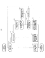
- FIG. 8 is a flowchart showing an example of stop limit point creation performed by the ground control device. First, it is determined whether a train is present ahead of its own train (S11). When the train does not exist ahead of the own train (S11: No), the maximum stop limit point on the system is set as the own train stop limit point (S17).
- the trouble position reset condition is when the driving direction of the oncoming train is switched (switched in the forward direction), or when the oncoming train exceeds the longest stop limit point of the oncoming train which has overrun and is held, Or when the oncoming train stops or when the course changes. If none of the obstacle position reset conditions is satisfied (S16: No), the obstacle position is held, and the point where the safety margin distance is secured at the obstacle position is set as the own train stop limit point (S19). If any one of the obstacle position reset conditions is satisfied (S16: Yes), the obstacle position is reset, and stop limit point creation is performed again. (S11).
- the present invention is not limited to the embodiments described above, but includes various embodiments.
- the above-described embodiment describes a train control system using wireless communication for data transmission and reception between the on-ground and the ground, like the conventional digital ATC, a train circuit instructs train control on the ground from the ground by a track circuit.
- the idea of creating the own train stop limit point from the longest stop limit point of the oncoming train at the time of train opposite can be used.
Abstract
列車が対向して走行する際の、安全を担保した停止限界点の作成方法を提供する。 このため、走行路を走行する列車の停止限界点を決定する列車制御装置であって、複数の前記列車が対向して走行する場合、前記列車の支障位置を対向する列車の最長の停止限界点に定め、そこに安全余裕距離を確保した地点を、前記列車の停止限界点として列車停止制御をする。
Description
本発明は、列車が演算した自列車の位置情報を地上システムに送信し、地上システムから列車に制御情報を送信し、当該制御情報に基づいて列車制御を行う列車制御システムに関する。
従来、列車の走行制御は、地上から車上へ送信する信号をデジタル情報とすることで、停止する軌道回路を地上システムから列車に送信することを可能とし、車上の自動列車制御装置は車両性能や路線条件に基づいて停止点に停止する一段階のブレーキ曲線を作成し、ブレーキ曲線より自列車速度が超過している場合には、自動的にブレーキを作動させることで、列車の時隔短縮や乗り心地向上が図られてきた。
従来のデジタルATC(Automatic Train Control)では、地上制御装置の列車検知は軌道回路を用いて行われ、地上から車上への制御情報の通知はレールを用いたデジタル伝送により実現されてきた。
一方、近年、無線技術の発展から、特許文献1に示すような無線を用いた列車制御システムが実用化されつつある。即ち、この列車制御システムにおいては、車上制御装置は、列車の位置を検知する機能を有し、検知した列車位置情報を無線通信部から地上側に送信する。地上側の制御装置は、車上の無線通信部からの列車位置情報を受信して列車が安全に走行できる限界位置である停止限界点(先行列車の位置から、走行許可位置を求める対象としている列車の位置検知誤差と、先行列車の位置検知誤差と、先行列車が後退する可能性のある距離とを差し引いた地点)を求め、無線通信を介して車上制御装置に通知し、車上制御装置は停止限界点を越えることがないように列車制御を行う。
一般的に、車上~地上間の双方向デジタル伝送に無線通信を利用した列車制御システムは、CBTC(Communication Based Train Control)と称される。無線を利用することで、地上~車上間での双方向通信が可能となるため、CBTCではデジタルATCの軌道回路で行っていた列車の在線検知に代わって、車上が演算し求めた自列車の位置情報を無線で地上に通知することによって列車検知を実現することができる。これにより、軌道回路単位の閉塞区間で在線検知を行っていた従来のシステムと比較して、CBTCでは実際の列車位置を検知することができ、地上制御装置は、これに基づいた停止限界点を後方列車に通知することで、デジタルATCよりも時隔・距離間隔を縮めた列車制御を実現することができる。
先行列車即ち対向列車と、後続列車即ち自列車が対向して走行するような場面で危険な事態が発生しないように、安全性を担保した列車制御を行う必要がある。なお、本開示において、「危険な事態」とは、危険な状態から結果として危害に至る事象を意味する。
列車が対向していない場合、列車同士の間隔を制御する方法としては、後続列車の支障位置を先行列車の最後尾として、そこから安全余裕距離を確保した地点までに停止制御を行う方法が有る。
これを応用して、列車が対向している場合の列車間隔を制御する方法としては、自列車の支障位置を、対向列車の停止限界点として、そこから安全余裕距離を確保した地点までに停止制御を行う方法が有る。
ここで、何らかの支障(列車防護、進路復位等)が対向列車の先頭位置から停止限界点の間で発生する事を考えると、対向列車停止限界点は、支障発生位置から安全余裕距離を確保した地点に短縮される。一方、自列車の停止限界点は、対向列車の停止限界点が短縮された為、それに伴って支障発生位置に安全余裕距離を確保した地点に延長され前方に進行できるようになる。
しかし、対向列車はブレーキ制御が間に合わず停止限界点を過走する可能性がある。そこで、自列車は対向列車の先頭位置から安全余裕距離を確保した位置に停止限界点を短縮する必要が有り、自列車の停止パターン範囲内で支障が発生していないにも関わらず、不要な緊急停止制御が行われてしまう問題が有る。また最悪の場合、対向列車が自列車の停止限界点を支障して危険な事態となる問題もある。
本発明の目的は、列車が対向して走行する際の、安全を担保した自列車の停止限界点の作成方法を提供する事にある。
上記課題を解決するために、代表的な本発明の列車制御装置の一つは、走行路を走行する列車の停止限界点を決定する列車制御装置であって、複数の列車が対向して走行する場合、一の列車である自列車の支障位置を、対向する列車である対向列車の停止限界点である対向列車停止限界点に定め、また自列車支障位置は最遠方に保持し、自列車支障位置から安全余裕距離だけ自列車に近づけた地点を、自列車の停止限界点とすることにより達成される。
本発明によれば、対向して走行する状況において、安全性を担保した停止限界点作成方法を提供する事によって、不要な緊急停止制御や危険な事態に陥る事を防ぎつつ安全性を確保する事が出来る。
以下、図面を参照して、本発明による列車制御装置の実施形態について説明する。
図1には、車上システムと地上システムとから成る列車制御システムの概略図が示されている。車上システムは、車上制御装置10と車上無線機11から構成されている。地上システムは、車上無線機11との間で無線通信を行う地上無線機21と、路線に在線する列車の間隔制御を行う地上制御装置20とから構成されている。
車上制御装置10は自列車位置を演算している。車上制御装置10は、車上無線機11と地上無線機21間の双方向通信により、当該自列車位置の位置情報30を地上制御装置20へ通知する。地上制御装置20は、列車から通知のあった位置情報30に基づいて、先行列車100からの安全余裕距離300を考慮した後続列車200の停止限界点201を演算し、制御情報40として後続列車200へ無線通信により通知する。
上記システムにおいて、先行列車即ち対向列車と、後続列車即ち自列車が対向して走行するような場面で危険な事態とならないように、安全性を担保した列車制御を行う必要がある。
列車が対向していない場合、列車同士の間隔を制御する方法としては、後続列車200の支障位置は、先行列車100の最後尾となり、そこから安全余裕距離300を確保した地点までに停止制御を行う方法が有る。
これを応用して列車が対向している場合の列車間隔を制御する方法としては、図2に示すように、自列車支障位置206を対向列車停止限界点104として、そこから安全余裕距離300を確保した地点までに停止制御を行う方法が有る。
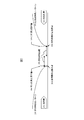
しかし、図3に示すように、何らかの支障、例えば列車防護400が対向列車停止パターン105の範囲内で発生した場合、対向列車停止限界点104は、列車防護400の位置から安全余裕距離300を確保した地点に短縮される。一方、自列車停止限界点204は、対向列車停止限界点104が短縮された為、それに連動して列車防護400の位置に安全余裕距離300を確保した地点に延長され、前方に進行できるようになる。前記の何らかの支障は進路復位等の場合もありうる。
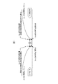
次に、図4に示すように、対向列車103のブレーキ制御が間に合わずに過走して、自列車停止限界点204に到達する事を想定すると、自列車停止限界点204は対向列車103の先頭位置から安全余裕距離300を確保した位置に停止限界点を短縮する為、自列車停止パターン205の範囲内で支障が発生していないにも関わらず、不要な緊急停止制御を行う事になる。また最悪の場合、対向列車103が自列車停止限界点204を支障して危険な事態と判断される。
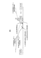
上記事象を防ぐ為に、地上制御装置が先行列車の運転方向転換を検知して列車対向の状態になった場合は、図5に示すように、自列車支障位置206を最長の対向列車停止限界点104とし、そこに安全余裕距離300を確保した地点までに停止させるようにし、対向列車の運転方向に向かって停止限界点が対向列車の遠方に更新された時は、最新の停止限界点を最長の対向列車停止限界点104に更新して保持する。また、対向列車支障位置106も同様で、対向列車支障位置106を最長の自列車停止限界点204とし、そこに安全余裕距離300を確保した地点までに停止させるようにし、自列車の運転方向に向かって停止限界点が遠方に更新された時は、最新の停止限界点を最長の自列車停止限界点204に更新して保持する。
図5で、地上制御装置が先行列車の運転方向転換を検知した場合に、列車の支障位置を対向列車の最長の停止限界点としたが、運転方向によらず常時、支障位置を列車の最長の停止限界点としても良い。
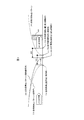
前述の停止点作成方法により、図6に示すように、仮に対向列車が列車防護を過走したとしても、自列車停止限界点204の短縮は発生しない。
また、対向列車103が運転方向を順方向に戻した場合、図7に示すように、保持していた自列車支障位置206を解除して、対向列車の最後尾にリセットする。つまり、自列車203及び対向列車103が同一方向に進行していた当所の初期状態に戻す。また、自列車停止限界点204を対向列車の最後尾から安全余裕距離300を確保した地点まで延長する。自列車支障位置206の保持解除条件は列車走行進路が変更となった場合、又は対向列車103が過走して最長の対向列車停止限界点104を超えた場合も成立する。
また、対向列車103が停止した場合、それまで保持していた対向列車103の最長の対向列車停止限界点104は一旦リセットするが、列車が対向して走行する限りは、対向列車103の最長の対向列車停止限界点104に安全余裕距離300を確保した地点を再度演算して、自列車停止限界点204に反映する。
上記は、先行する列車を対向列車、後続の列車を自列車として説明したが、先行する列車を自列車、後続の列車を対向列車に読み替えることもできる。
図8は地上制御装置によって行われる停止限界点作成の一例を示すフローチャートである。まず、自列車の前方に列車が在線しているか判定する(S11)。自列車の前方に列車が在線していない場合(S11:No)は、システム上可能な最大の停止限界点を自列車停止限界点とする(S17)。
自列車の前方に列車が在線している場合(S11:Yes)は、前方の列車が対向しているか判定する(S12)。前方の列車が対向していない場合(S12:No)は、先行列車の最後尾から安全余裕距離を確保した地点を自列車停止限界点とする(S18)。前方の列車が対向している場合(S12:Yes)は、支障位置を前回の支障位置とする(S13)。
次に、対向列車の停止限界点が遠方に更新されたか判定する(S14)。対向列車の停止限界点が遠方に更新されている場合(S14:Yes)は、支障位置を対向列車の最新の停止限界点とする(S15)。
次に、支障位置リセット条件が何れか1つでも成立しているか判定する(S16)。ここで、支障位置リセット条件とは、対向列車の運転方向切替(順方向へ切替)えた時、又は対向列車が過走して保持していた対向列車の最長の停止限界点を超えた時、又は対向列車が停止した時、又は進路が変更となった時である。支障位置リセット条件がいずれも成立していない場合(S16:No)、支障位置を保持し、支障位置に安全余裕距離を確保した地点を自列車停止限界点とする(S19)。支障位置リセット条件が何れか1つでも成立している場合(S16:Yes)は、支障位置をリセットし、再度停止限界点作成をやり直す。(S11)。
本発明は、上記した実施例に限定されるものでは無く、様々な実施例が含まれる。例えば、上記した実施例は車上~地上間のデータ送受信に無線通信を利用した列車制御システムについて説明しているが、従来のデジタルATCのように軌道回路により地上から車上に列車制御指示を送信するシステムにおいても、列車対向時に自列車停止限界点を対向列車の最長の停止限界点から作成する考えは使用できる。
10:車上制御装置 11:車上無線機
20:地上制御装置 21:地上無線機
30:位置情報 40:制御情報
100:先行列車
103:対向列車
104:対向列車停止限界点
105:対向列車停止パターン
106:対向列車支障位置
200:後続列車
201:後続列車停止限界点
202:後続列車停止パターン
203:自列車
204:自列車停止限界点
205:自列車停止パターン
206:自列車支障位置
300:安全余裕距離
400:列車防護
20:地上制御装置 21:地上無線機
30:位置情報 40:制御情報
100:先行列車
103:対向列車
104:対向列車停止限界点
105:対向列車停止パターン
106:対向列車支障位置
200:後続列車
201:後続列車停止限界点
202:後続列車停止パターン
203:自列車
204:自列車停止限界点
205:自列車停止パターン
206:自列車支障位置
300:安全余裕距離
400:列車防護
Claims (8)
- 走行路を走行する列車の停止限界点を決定する列車制御装置であって、複数の前記列車が対向して走行する場合、一の前記列車である自列車の支障位置を、対向する前記列車の前記停止限界点に定め、前記自列車支障位置から安全余裕距離だけ前記自列車に近づけた地点を、前記自列車の前記停止限界点とすることを特徴とする列車制御装置。
- 請求項1に記載の列車制御装置において、前記対向列車の運転方向に向かって前記対向列車停止限界点が遠方に更新された時に、前記自列車支障位置を更新された前記対向列車停止限界点に更新することを特徴とする列車制御装置。
- 請求項1乃至請求項2のいずれか1つに記載の列車制御装置において、前記複数の前記列車が対向して走行する事を検知した場合に、前記自列車の支障位置及び前記対向列車の支障位置を保持する事を特徴とする列車制御装置。
- 請求項1乃至請求項3のいずれか1つに記載の列車制御装置において、前記対向列車停止限界点を前記自列車支障位置として保持する事を特徴とする列車制御装置。
- 請求項3乃至請求項4のいずれか1つに記載の列車制御装置において、前記対向列車の進路が変更された場合に、保持した前記自列車支障位置をリセットすることを特徴とする列車制御装置。
- 請求項3乃至請求項5のいずれか1つに記載の列車制御装置において、前記対向列車が過走して、前記自列車支障位置を超えた時に、前記自列車支障位置の保持を解除することを特徴とする列車制御装置。
- 請求項3乃至請求項6のいずれか1つに記載の列車制御装置において、前記対向列車が停止した場合に、前記自列車支障位置の保持を解除することを特徴とする列車制御装置。
- 走行路を走行する列車の停止限界点を決定する列車制御装置であって、前記走行路を複数の前記列車が走行する場合、一の前記列車である自列車の支障位置を、常に最長の地点に保持する事を特徴とする列車制御装置。
Priority Applications (3)
| Application Number | Priority Date | Filing Date | Title |
|---|---|---|---|
| EP18863002.4A EP3689707A4 (en) | 2017-09-28 | 2018-03-27 | TRAIN CONTROL DEVICE |
| JP2019544222A JP6909303B2 (ja) | 2017-09-28 | 2018-03-27 | 列車制御装置 |
| CN201880042365.7A CN110799405B (zh) | 2017-09-28 | 2018-03-27 | 列车控制装置 |
Applications Claiming Priority (2)
| Application Number | Priority Date | Filing Date | Title |
|---|---|---|---|
| JP2017-187407 | 2017-09-28 | ||
| JP2017187407 | 2017-09-28 |
Publications (1)
| Publication Number | Publication Date |
|---|---|
| WO2019064649A1 true WO2019064649A1 (ja) | 2019-04-04 |
Family
ID=65901349
Family Applications (1)
| Application Number | Title | Priority Date | Filing Date |
|---|---|---|---|
| PCT/JP2018/012394 WO2019064649A1 (ja) | 2017-09-28 | 2018-03-27 | 列車制御装置 |
Country Status (4)
| Country | Link |
|---|---|
| EP (1) | EP3689707A4 (ja) |
| JP (1) | JP6909303B2 (ja) |
| CN (1) | CN110799405B (ja) |
| WO (1) | WO2019064649A1 (ja) |
Citations (4)
| Publication number | Priority date | Publication date | Assignee | Title |
|---|---|---|---|---|
| JPH0298069U (ja) * | 1989-01-23 | 1990-08-03 | ||
| JP2000159105A (ja) | 1998-11-24 | 2000-06-13 | Hitachi Ltd | 無線列車の列車間隔制御システム |
| JP2010120484A (ja) * | 2008-11-19 | 2010-06-03 | Hitachi Ltd | 列車停止制御システム |
| JP2013023037A (ja) * | 2011-07-19 | 2013-02-04 | Toshiba Corp | 列車制御装置 |
Family Cites Families (21)
| Publication number | Priority date | Publication date | Assignee | Title |
|---|---|---|---|---|
| DE19509696C2 (de) * | 1995-03-08 | 2000-04-13 | Siemens Ag | Verfahren zur gegenseitigen Kontaktaufnahme zwischen Zügen und Einrichtung zur Durchführung des Verfahrens |
| US5950966A (en) * | 1997-09-17 | 1999-09-14 | Westinghouse Airbrake Company | Distributed positive train control system |
| JP3663303B2 (ja) * | 1998-08-21 | 2005-06-22 | トヨタ自動車株式会社 | 車両運行制御方法及び車両運行支援装置 |
| JP4454303B2 (ja) * | 2003-12-22 | 2010-04-21 | 株式会社日立製作所 | 信号保安システム |
| DE102007015578A1 (de) * | 2007-03-28 | 2008-10-09 | Siemens Ag | Verfahren und Vorrichtung zur automatischen Steuerung eines spurgebundenes Fahrzeugs sowie Strecke für spurgebundene Fahrzeuge |
| JP5558317B2 (ja) * | 2010-11-09 | 2014-07-23 | 株式会社東芝 | 列車制御装置 |
| US8967553B2 (en) * | 2011-06-23 | 2015-03-03 | Mitsubishi Electric Corporation | Train operation control system |
| JP5827509B2 (ja) * | 2011-07-22 | 2015-12-02 | 株式会社日立製作所 | 無線列車制御システム |
| JP5759331B2 (ja) * | 2011-09-30 | 2015-08-05 | 日本信号株式会社 | 列車制御システム |
| CN202243552U (zh) * | 2011-10-09 | 2012-05-30 | 株洲普天中普防雷科技有限公司 | 一种列车主动防追尾控制系统装置 |
| CN102514598B (zh) * | 2011-12-20 | 2015-03-11 | 北京交通大学 | 高铁信号系统级“故障-安全”方法 |
| US9642163B2 (en) * | 2012-06-29 | 2017-05-02 | Mitsubishi Electric Corporation | Train control device |
| JP6001467B2 (ja) * | 2013-01-28 | 2016-10-05 | 株式会社日立製作所 | 信号保安システム |
| DE102014203666A1 (de) * | 2014-02-28 | 2015-09-03 | Siemens Aktiengesellschaft | Verfahren und Anordnung zum Betreiben funkzugbeeinflusster spurgebundener Fahrzeuge |
| US11760396B2 (en) * | 2014-04-25 | 2023-09-19 | Nabil N. Ghaly | Method and apparatus for an auxiliary train control system |
| DE102014210190A1 (de) * | 2014-05-28 | 2015-12-03 | Siemens Aktiengesellschaft | Fahrerlaubnis für ein Schienenfahrzeug |
| DE102015204769A1 (de) * | 2015-03-17 | 2016-09-22 | Siemens Aktiengesellschaft | Verfahren sowie Vorrichtung zur automatischen Beeinflussung spurgebundener Fahrzeuge |
| CN105101094B (zh) * | 2015-09-17 | 2018-10-12 | 北京交通大学 | 列车运行控制系统 |
| DE102015218971A1 (de) * | 2015-09-30 | 2017-03-30 | Siemens Aktiengesellschaft | Sicherungsverfahren für ein Gleisstreckennetz |
| US11040732B2 (en) * | 2016-03-09 | 2021-06-22 | Mitsubishi Electric Corporation | Wireless train control system, ground control device, and wireless train control method |
| CN106347414B (zh) * | 2016-08-31 | 2018-06-05 | 交控科技股份有限公司 | 一种用于列车相向运行时移动授权的计算方法以及装置 |
-
2018
- 2018-03-27 CN CN201880042365.7A patent/CN110799405B/zh active Active
- 2018-03-27 JP JP2019544222A patent/JP6909303B2/ja active Active
- 2018-03-27 EP EP18863002.4A patent/EP3689707A4/en active Pending
- 2018-03-27 WO PCT/JP2018/012394 patent/WO2019064649A1/ja unknown
Patent Citations (4)
| Publication number | Priority date | Publication date | Assignee | Title |
|---|---|---|---|---|
| JPH0298069U (ja) * | 1989-01-23 | 1990-08-03 | ||
| JP2000159105A (ja) | 1998-11-24 | 2000-06-13 | Hitachi Ltd | 無線列車の列車間隔制御システム |
| JP2010120484A (ja) * | 2008-11-19 | 2010-06-03 | Hitachi Ltd | 列車停止制御システム |
| JP2013023037A (ja) * | 2011-07-19 | 2013-02-04 | Toshiba Corp | 列車制御装置 |
Non-Patent Citations (1)
| Title |
|---|
| See also references of EP3689707A4 |
Also Published As
| Publication number | Publication date |
|---|---|
| EP3689707A1 (en) | 2020-08-05 |
| CN110799405A (zh) | 2020-02-14 |
| CN110799405B (zh) | 2021-12-28 |
| JP6909303B2 (ja) | 2021-07-28 |
| EP3689707A4 (en) | 2021-06-23 |
| JPWO2019064649A1 (ja) | 2020-04-16 |
Similar Documents
| Publication | Publication Date | Title |
|---|---|---|
| CN110758484B (zh) | 列车自动驾驶方法、vobc、tias、区域控制器 | |
| KR102096963B1 (ko) | 열차 간 가상 연결 방법 및 이를 위한 열차 제어 장치 | |
| JP6228882B2 (ja) | 列車制御方法及び列車制御システム | |
| WO2013146427A1 (ja) | 列車制御装置 | |
| KR102338241B1 (ko) | 열차 속도 임시 제한 장치 | |
| JP2018172053A (ja) | 列車運行制御システム | |
| JP5042066B2 (ja) | 列車制御システム | |
| US10449983B2 (en) | Method for commanding a railway level crossing protection system | |
| JP2009232574A (ja) | 列車制御装置 | |
| KR101355672B1 (ko) | 열차제어장치 및 열차제어방법 | |
| WO2019064649A1 (ja) | 列車制御装置 | |
| JP2013082240A (ja) | 地上装置、車上装置、列車制御システム及び制御方法 | |
| JP6808826B2 (ja) | 自動列車保安装置及び車上装置 | |
| JP7191452B2 (ja) | 列車制御システム | |
| JP6789885B2 (ja) | 車上制御装置及び列車制御システム | |
| KR101055797B1 (ko) | 궤도회로기반 연속제어 열차방호방법 | |
| JP6945395B2 (ja) | 列車防護無線制御システム | |
| JP2011010515A (ja) | 電気車の無線保安用制御装置 | |
| KR20160071645A (ko) | 열차의 분리-결합 시스템 | |
| JP6839066B2 (ja) | 列車制御システムおよび運行管理装置 | |
| JP2015048038A (ja) | 列車制御システム | |
| JP4757045B2 (ja) | 列車制御装置 | |
| JP6725998B2 (ja) | 踏切制御装置 | |
| JP5897480B2 (ja) | 列車制御システム | |
| JP7466494B2 (ja) | 列車制御システム及び列車制御装置 |
Legal Events
| Date | Code | Title | Description |
|---|---|---|---|
| 121 | Ep: the epo has been informed by wipo that ep was designated in this application |
Ref document number: 18863002 Country of ref document: EP Kind code of ref document: A1 |
|
| ENP | Entry into the national phase |
Ref document number: 2019544222 Country of ref document: JP Kind code of ref document: A |
|
| NENP | Non-entry into the national phase |
Ref country code: DE |
|
| ENP | Entry into the national phase |
Ref document number: 2018863002 Country of ref document: EP Effective date: 20200428 |