WO2019059259A1 - Matériau magnétique et procédé pour la production de celui-ci - Google Patents
Matériau magnétique et procédé pour la production de celui-ci Download PDFInfo
- Publication number
- WO2019059259A1 WO2019059259A1 PCT/JP2018/034752 JP2018034752W WO2019059259A1 WO 2019059259 A1 WO2019059259 A1 WO 2019059259A1 JP 2018034752 W JP2018034752 W JP 2018034752W WO 2019059259 A1 WO2019059259 A1 WO 2019059259A1
- Authority
- WO
- WIPO (PCT)
- Prior art keywords
- phase
- magnetic material
- component
- atomic
- content
- Prior art date
Links
Images


Classifications
-
- C—CHEMISTRY; METALLURGY
- C22—METALLURGY; FERROUS OR NON-FERROUS ALLOYS; TREATMENT OF ALLOYS OR NON-FERROUS METALS
- C22C—ALLOYS
- C22C33/00—Making ferrous alloys
- C22C33/02—Making ferrous alloys by powder metallurgy
- C22C33/0235—Starting from compounds, e.g. oxides
-
- B—PERFORMING OPERATIONS; TRANSPORTING
- B22—CASTING; POWDER METALLURGY
- B22F—WORKING METALLIC POWDER; MANUFACTURE OF ARTICLES FROM METALLIC POWDER; MAKING METALLIC POWDER; APPARATUS OR DEVICES SPECIALLY ADAPTED FOR METALLIC POWDER
- B22F1/00—Metallic powder; Treatment of metallic powder, e.g. to facilitate working or to improve properties
- B22F1/05—Metallic powder characterised by the size or surface area of the particles
-
- B—PERFORMING OPERATIONS; TRANSPORTING
- B22—CASTING; POWDER METALLURGY
- B22F—WORKING METALLIC POWDER; MANUFACTURE OF ARTICLES FROM METALLIC POWDER; MAKING METALLIC POWDER; APPARATUS OR DEVICES SPECIALLY ADAPTED FOR METALLIC POWDER
- B22F1/00—Metallic powder; Treatment of metallic powder, e.g. to facilitate working or to improve properties
- B22F1/07—Metallic powder characterised by particles having a nanoscale microstructure
-
- B—PERFORMING OPERATIONS; TRANSPORTING
- B22—CASTING; POWDER METALLURGY
- B22F—WORKING METALLIC POWDER; MANUFACTURE OF ARTICLES FROM METALLIC POWDER; MAKING METALLIC POWDER; APPARATUS OR DEVICES SPECIALLY ADAPTED FOR METALLIC POWDER
- B22F3/00—Manufacture of workpieces or articles from metallic powder characterised by the manner of compacting or sintering; Apparatus specially adapted therefor ; Presses and furnaces
-
- B—PERFORMING OPERATIONS; TRANSPORTING
- B22—CASTING; POWDER METALLURGY
- B22F—WORKING METALLIC POWDER; MANUFACTURE OF ARTICLES FROM METALLIC POWDER; MAKING METALLIC POWDER; APPARATUS OR DEVICES SPECIALLY ADAPTED FOR METALLIC POWDER
- B22F5/00—Manufacture of workpieces or articles from metallic powder characterised by the special shape of the product
-
- B—PERFORMING OPERATIONS; TRANSPORTING
- B22—CASTING; POWDER METALLURGY
- B22F—WORKING METALLIC POWDER; MANUFACTURE OF ARTICLES FROM METALLIC POWDER; MAKING METALLIC POWDER; APPARATUS OR DEVICES SPECIALLY ADAPTED FOR METALLIC POWDER
- B22F9/00—Making metallic powder or suspensions thereof
- B22F9/16—Making metallic powder or suspensions thereof using chemical processes
- B22F9/18—Making metallic powder or suspensions thereof using chemical processes with reduction of metal compounds
- B22F9/20—Making metallic powder or suspensions thereof using chemical processes with reduction of metal compounds starting from solid metal compounds
- B22F9/22—Making metallic powder or suspensions thereof using chemical processes with reduction of metal compounds starting from solid metal compounds using gaseous reductors
-
- C—CHEMISTRY; METALLURGY
- C01—INORGANIC CHEMISTRY
- C01G—COMPOUNDS CONTAINING METALS NOT COVERED BY SUBCLASSES C01D OR C01F
- C01G49/00—Compounds of iron
-
- C—CHEMISTRY; METALLURGY
- C01—INORGANIC CHEMISTRY
- C01G—COMPOUNDS CONTAINING METALS NOT COVERED BY SUBCLASSES C01D OR C01F
- C01G51/00—Compounds of cobalt
-
- C—CHEMISTRY; METALLURGY
- C01—INORGANIC CHEMISTRY
- C01G—COMPOUNDS CONTAINING METALS NOT COVERED BY SUBCLASSES C01D OR C01F
- C01G53/00—Compounds of nickel
-
- C—CHEMISTRY; METALLURGY
- C22—METALLURGY; FERROUS OR NON-FERROUS ALLOYS; TREATMENT OF ALLOYS OR NON-FERROUS METALS
- C22C—ALLOYS
- C22C33/00—Making ferrous alloys
- C22C33/02—Making ferrous alloys by powder metallurgy
- C22C33/0257—Making ferrous alloys by powder metallurgy characterised by the range of the alloying elements
-
- C—CHEMISTRY; METALLURGY
- C22—METALLURGY; FERROUS OR NON-FERROUS ALLOYS; TREATMENT OF ALLOYS OR NON-FERROUS METALS
- C22C—ALLOYS
- C22C38/00—Ferrous alloys, e.g. steel alloys
-
- C—CHEMISTRY; METALLURGY
- C22—METALLURGY; FERROUS OR NON-FERROUS ALLOYS; TREATMENT OF ALLOYS OR NON-FERROUS METALS
- C22C—ALLOYS
- C22C38/00—Ferrous alloys, e.g. steel alloys
- C22C38/02—Ferrous alloys, e.g. steel alloys containing silicon
-
- C—CHEMISTRY; METALLURGY
- C22—METALLURGY; FERROUS OR NON-FERROUS ALLOYS; TREATMENT OF ALLOYS OR NON-FERROUS METALS
- C22C—ALLOYS
- C22C38/00—Ferrous alloys, e.g. steel alloys
- C22C38/04—Ferrous alloys, e.g. steel alloys containing manganese
-
- C—CHEMISTRY; METALLURGY
- C22—METALLURGY; FERROUS OR NON-FERROUS ALLOYS; TREATMENT OF ALLOYS OR NON-FERROUS METALS
- C22C—ALLOYS
- C22C38/00—Ferrous alloys, e.g. steel alloys
- C22C38/08—Ferrous alloys, e.g. steel alloys containing nickel
-
- C—CHEMISTRY; METALLURGY
- C22—METALLURGY; FERROUS OR NON-FERROUS ALLOYS; TREATMENT OF ALLOYS OR NON-FERROUS METALS
- C22C—ALLOYS
- C22C38/00—Ferrous alloys, e.g. steel alloys
- C22C38/10—Ferrous alloys, e.g. steel alloys containing cobalt
-
- C—CHEMISTRY; METALLURGY
- C22—METALLURGY; FERROUS OR NON-FERROUS ALLOYS; TREATMENT OF ALLOYS OR NON-FERROUS METALS
- C22C—ALLOYS
- C22C38/00—Ferrous alloys, e.g. steel alloys
- C22C38/16—Ferrous alloys, e.g. steel alloys containing copper
-
- H—ELECTRICITY
- H01—ELECTRIC ELEMENTS
- H01F—MAGNETS; INDUCTANCES; TRANSFORMERS; SELECTION OF MATERIALS FOR THEIR MAGNETIC PROPERTIES
- H01F1/00—Magnets or magnetic bodies characterised by the magnetic materials therefor; Selection of materials for their magnetic properties
- H01F1/01—Magnets or magnetic bodies characterised by the magnetic materials therefor; Selection of materials for their magnetic properties of inorganic materials
- H01F1/03—Magnets or magnetic bodies characterised by the magnetic materials therefor; Selection of materials for their magnetic properties of inorganic materials characterised by their coercivity
- H01F1/12—Magnets or magnetic bodies characterised by the magnetic materials therefor; Selection of materials for their magnetic properties of inorganic materials characterised by their coercivity of soft-magnetic materials
- H01F1/34—Magnets or magnetic bodies characterised by the magnetic materials therefor; Selection of materials for their magnetic properties of inorganic materials characterised by their coercivity of soft-magnetic materials non-metallic substances, e.g. ferrites
- H01F1/342—Oxides
- H01F1/344—Ferrites, e.g. having a cubic spinel structure (X2+O)(Y23+O3), e.g. magnetite Fe3O4
-
- H—ELECTRICITY
- H01—ELECTRIC ELEMENTS
- H01F—MAGNETS; INDUCTANCES; TRANSFORMERS; SELECTION OF MATERIALS FOR THEIR MAGNETIC PROPERTIES
- H01F1/00—Magnets or magnetic bodies characterised by the magnetic materials therefor; Selection of materials for their magnetic properties
- H01F1/01—Magnets or magnetic bodies characterised by the magnetic materials therefor; Selection of materials for their magnetic properties of inorganic materials
- H01F1/03—Magnets or magnetic bodies characterised by the magnetic materials therefor; Selection of materials for their magnetic properties of inorganic materials characterised by their coercivity
- H01F1/12—Magnets or magnetic bodies characterised by the magnetic materials therefor; Selection of materials for their magnetic properties of inorganic materials characterised by their coercivity of soft-magnetic materials
- H01F1/34—Magnets or magnetic bodies characterised by the magnetic materials therefor; Selection of materials for their magnetic properties of inorganic materials characterised by their coercivity of soft-magnetic materials non-metallic substances, e.g. ferrites
- H01F1/36—Magnets or magnetic bodies characterised by the magnetic materials therefor; Selection of materials for their magnetic properties of inorganic materials characterised by their coercivity of soft-magnetic materials non-metallic substances, e.g. ferrites in the form of particles
-
- B—PERFORMING OPERATIONS; TRANSPORTING
- B22—CASTING; POWDER METALLURGY
- B22F—WORKING METALLIC POWDER; MANUFACTURE OF ARTICLES FROM METALLIC POWDER; MAKING METALLIC POWDER; APPARATUS OR DEVICES SPECIALLY ADAPTED FOR METALLIC POWDER
- B22F1/00—Metallic powder; Treatment of metallic powder, e.g. to facilitate working or to improve properties
- B22F1/08—Metallic powder characterised by particles having an amorphous microstructure
-
- B—PERFORMING OPERATIONS; TRANSPORTING
- B22—CASTING; POWDER METALLURGY
- B22F—WORKING METALLIC POWDER; MANUFACTURE OF ARTICLES FROM METALLIC POWDER; MAKING METALLIC POWDER; APPARATUS OR DEVICES SPECIALLY ADAPTED FOR METALLIC POWDER
- B22F2207/00—Aspects of the compositions, gradients
- B22F2207/01—Composition gradients
-
- B—PERFORMING OPERATIONS; TRANSPORTING
- B22—CASTING; POWDER METALLURGY
- B22F—WORKING METALLIC POWDER; MANUFACTURE OF ARTICLES FROM METALLIC POWDER; MAKING METALLIC POWDER; APPARATUS OR DEVICES SPECIALLY ADAPTED FOR METALLIC POWDER
- B22F2301/00—Metallic composition of the powder or its coating
- B22F2301/35—Iron
-
- B—PERFORMING OPERATIONS; TRANSPORTING
- B22—CASTING; POWDER METALLURGY
- B22F—WORKING METALLIC POWDER; MANUFACTURE OF ARTICLES FROM METALLIC POWDER; MAKING METALLIC POWDER; APPARATUS OR DEVICES SPECIALLY ADAPTED FOR METALLIC POWDER
- B22F2998/00—Supplementary information concerning processes or compositions relating to powder metallurgy
- B22F2998/10—Processes characterised by the sequence of their steps
-
- B—PERFORMING OPERATIONS; TRANSPORTING
- B22—CASTING; POWDER METALLURGY
- B22F—WORKING METALLIC POWDER; MANUFACTURE OF ARTICLES FROM METALLIC POWDER; MAKING METALLIC POWDER; APPARATUS OR DEVICES SPECIALLY ADAPTED FOR METALLIC POWDER
- B22F2999/00—Aspects linked to processes or compositions used in powder metallurgy
-
- C—CHEMISTRY; METALLURGY
- C22—METALLURGY; FERROUS OR NON-FERROUS ALLOYS; TREATMENT OF ALLOYS OR NON-FERROUS METALS
- C22C—ALLOYS
- C22C2200/00—Crystalline structure
- C22C2200/04—Nanocrystalline
-
- C—CHEMISTRY; METALLURGY
- C22—METALLURGY; FERROUS OR NON-FERROUS ALLOYS; TREATMENT OF ALLOYS OR NON-FERROUS METALS
- C22C—ALLOYS
- C22C2202/00—Physical properties
- C22C2202/02—Magnetic
-
- H—ELECTRICITY
- H01—ELECTRIC ELEMENTS
- H01F—MAGNETS; INDUCTANCES; TRANSFORMERS; SELECTION OF MATERIALS FOR THEIR MAGNETIC PROPERTIES
- H01F1/00—Magnets or magnetic bodies characterised by the magnetic materials therefor; Selection of materials for their magnetic properties
- H01F1/01—Magnets or magnetic bodies characterised by the magnetic materials therefor; Selection of materials for their magnetic properties of inorganic materials
- H01F1/03—Magnets or magnetic bodies characterised by the magnetic materials therefor; Selection of materials for their magnetic properties of inorganic materials characterised by their coercivity
- H01F1/032—Magnets or magnetic bodies characterised by the magnetic materials therefor; Selection of materials for their magnetic properties of inorganic materials characterised by their coercivity of hard-magnetic materials
- H01F1/04—Magnets or magnetic bodies characterised by the magnetic materials therefor; Selection of materials for their magnetic properties of inorganic materials characterised by their coercivity of hard-magnetic materials metals or alloys
- H01F1/047—Alloys characterised by their composition
- H01F1/053—Alloys characterised by their composition containing rare earth metals
- H01F1/055—Alloys characterised by their composition containing rare earth metals and magnetic transition metals, e.g. SmCo5
- H01F1/0553—Alloys characterised by their composition containing rare earth metals and magnetic transition metals, e.g. SmCo5 obtained by reduction or by hydrogen decrepitation or embrittlement
-
- H—ELECTRICITY
- H01—ELECTRIC ELEMENTS
- H01F—MAGNETS; INDUCTANCES; TRANSFORMERS; SELECTION OF MATERIALS FOR THEIR MAGNETIC PROPERTIES
- H01F1/00—Magnets or magnetic bodies characterised by the magnetic materials therefor; Selection of materials for their magnetic properties
- H01F1/01—Magnets or magnetic bodies characterised by the magnetic materials therefor; Selection of materials for their magnetic properties of inorganic materials
- H01F1/03—Magnets or magnetic bodies characterised by the magnetic materials therefor; Selection of materials for their magnetic properties of inorganic materials characterised by their coercivity
- H01F1/12—Magnets or magnetic bodies characterised by the magnetic materials therefor; Selection of materials for their magnetic properties of inorganic materials characterised by their coercivity of soft-magnetic materials
- H01F1/14—Magnets or magnetic bodies characterised by the magnetic materials therefor; Selection of materials for their magnetic properties of inorganic materials characterised by their coercivity of soft-magnetic materials metals or alloys
- H01F1/147—Alloys characterised by their composition
-
- H—ELECTRICITY
- H01—ELECTRIC ELEMENTS
- H01F—MAGNETS; INDUCTANCES; TRANSFORMERS; SELECTION OF MATERIALS FOR THEIR MAGNETIC PROPERTIES
- H01F1/00—Magnets or magnetic bodies characterised by the magnetic materials therefor; Selection of materials for their magnetic properties
- H01F1/01—Magnets or magnetic bodies characterised by the magnetic materials therefor; Selection of materials for their magnetic properties of inorganic materials
- H01F1/03—Magnets or magnetic bodies characterised by the magnetic materials therefor; Selection of materials for their magnetic properties of inorganic materials characterised by their coercivity
- H01F1/12—Magnets or magnetic bodies characterised by the magnetic materials therefor; Selection of materials for their magnetic properties of inorganic materials characterised by their coercivity of soft-magnetic materials
- H01F1/14—Magnets or magnetic bodies characterised by the magnetic materials therefor; Selection of materials for their magnetic properties of inorganic materials characterised by their coercivity of soft-magnetic materials metals or alloys
- H01F1/20—Magnets or magnetic bodies characterised by the magnetic materials therefor; Selection of materials for their magnetic properties of inorganic materials characterised by their coercivity of soft-magnetic materials metals or alloys in the form of particles, e.g. powder
- H01F1/22—Magnets or magnetic bodies characterised by the magnetic materials therefor; Selection of materials for their magnetic properties of inorganic materials characterised by their coercivity of soft-magnetic materials metals or alloys in the form of particles, e.g. powder pressed, sintered, or bound together
Definitions
- the present invention relates to a magnetic material exhibiting a soft magnetic material or a semi-hard magnetic material, in particular, a magnetic material exhibiting soft magnetism, and a method of manufacturing the same.
- the existing soft magnetic materials used for the above applications are roughly classified into two types, metal-based magnetic materials and oxide-based magnetic materials.
- the former metal-based magnetic materials include silicon steel (Fe-Si), which is a crystalline material containing Si, which is a typical case of electromagnetic steel, and Sendust (Fe-Al-Si), which is an intermetallic compound containing Al. And C, low-carbon and low-impurity pure iron with a carbon content of less than 0.3% by mass, electromagnetic soft iron (Fe), permalloy mainly composed of Fe-Ni, metglas (Fe-Si-B), etc.
- Si silicon steel
- Sendust Fe-Al-Si
- C low-carbon and low-impurity pure iron with a carbon content of less than 0.3% by mass
- electromagnetic soft iron (Fe) permalloy mainly composed of Fe-Ni, metglas (Fe-Si-B), etc.
- Amorphous alloys, and nanocrystalline soft magnetic materials such as FINEMET, which is a nanocrystal-amorphous phase separation type in which fine crystals are precipitated by applying appropriate heat treatment to the amorphous alloy (Fe as a typical composition thereof -Cu-Nb-Si-B, Fe-Si-B-P-Cu, etc.).
- the term "nano” as used herein refers to a size of at least 1 nm and less than 1 ⁇ m.
- the nanocrystalline soft magnetic material is an inhomogeneous system including a crystal phase, an amorphous phase, a Cu-enriched phase, and the like, and the magnetization reversal is considered to be mainly due to magnetization rotation.
- oxide-based magnetic materials examples include ferrite-based magnetic materials such as Mn--Zn ferrite and Ni--Zn ferrite.
- Silicon steel is the most widely used soft magnetic material for high-performance soft magnetic material applications, and its high saturation magnetization with a saturation magnetization of 1.6 to 2.0 T and a coercive force of 3 to 130 A / m. It is a magnetic material of magnetic force.
- This material is a material in which Si is added to about 4% by mass to Fe, and the coercive force is reduced by reducing the magnetocrystalline anisotropy and the saturation magnetostriction constant without largely damaging the large magnetization of Fe. is there.
- materials appropriately controlled in composition are appropriately combined with hot and cold rolling and annealing to remove foreign matter that impedes the movement of the domain wall while increasing the crystal grain size. It is necessary to.
- This material is a rolled material with a thickness of less than 0.5 mm in general, and a homogeneous metal material with a low electrical resistivity of approximately 0.5 ⁇ m.
- the surface of each silicon steel plate is covered with an insulating film It is applied to large-sized equipment by giving thickness and suppressing eddy current loss that occurs in high-speed applications such as next-generation vehicles by punching out with a die, laminating, and welding. Therefore, the process cost for punching and stacking and the deterioration of the magnetic characteristics are a serious problem.
- Nanocrystalline soft magnetic materials such as Fe-Cu-Nb-Si-B are heat-treated at a temperature higher than the crystallization temperature for alloys that have become amorphous by quenching once, so that crystal grains of about 10 nm can be obtained. It is a soft magnetic material having a randomly oriented nanocrystal-type structure which is precipitated in an amorphous state and has an amorphous grain boundary phase. The coercivity of this material is extremely low at 0.6 to 6 A / m, and the saturation magnetization is higher at 1.2 to 1.7 T than that of amorphous materials, so the market is currently expanding.
- This material is a relatively new material developed in 1988, and the principle of its magnetic property expression is to make the crystal grain size smaller than the ferromagnetic exchange length (also called exchange coupling length), and to randomly oriented main phase
- the ferromagnetic phase of (1) is ferromagnetically coupled through the amorphous interface phase, thereby averaging the magnetocrystalline magnetic anisotropy and achieving a low coercive force.
- This mechanism is called a random magnetic anisotropy model or a random anisotropy model (see, for example, Non-Patent Document 1).
- the product thickness is about 0.02 to 0.025 mm, and insulation, cutting, alignment, lamination, lamination, The process of welding and annealing is more complicated than silicon steel, and has problems such as processability and thermal stability. Furthermore, the electrical resistivity is as low as 1.2 ⁇ m, and the problems of eddy current loss similar to other rolled materials and strips are pointed out.
- the ferrite-based oxide material is the one with the largest eddy current loss problem in high-rotation applications.
- the electrical resistivity of this material is 10 6 to 10 12 ⁇ m, and it can be easily bulked to 0.5 mm or more by sintering, and it can be made into a compact without eddy current loss, so it is suitable for high rotation and high frequency applications. It is a suitable material.
- it since it is an oxide, it does not rust and is excellent in the stability of the magnetic characteristics.
- the coercivity of this material is relatively high at 2 to 160 A / m, and in particular, because the saturation magnetization is as low as 0.3 to 0.5 T, it is not suitable for, for example, a high-performance high-rotation motor for next-generation vehicles.
- metallic soft magnetic materials such as silicon steel are rolled materials and used because they are thin and laminated, but they are used with low electrical resistance, and eddy current loss occurs for high-performance motors with high rotation speed.
- eddy current loss occurs for high-performance motors with high rotation speed.
- oxide-based soft magnetic materials such as ferrite have high electrical resistance and no problem with eddy current loss, but their saturation magnetization is as small as 0.5 T or less, so they are suitable for high-performance motors for next-generation vehicles Absent.
- oxide soft magnetic materials are more stable and superior to metal soft magnetic materials.
- the thickness of the motor is about 0.3 mm
- the thickness of the motor for the next generation automobile is, for example, 9 cm, so when using a thin silicon steel plate such as 0.3 mm thick, insulate about 300 sheets each It will have to be stacked.
- the steps of insulating, punching, aligning, welding and annealing such thin plates are complicated and expensive. In order to increase the thickness of the laminated plate as much as possible, it is more desirable to increase the electrical resistivity of the material.
- a magnetic material having high oxidation resistance in particular, excellent in magnetic stability having both high saturation magnetization and low coercivity
- conventional oxide-based magnetic materials particularly ferrite-based magnetic materials
- soft magnetic materials capable of exhibiting the advantages of both an oxide magnetic material and a metal magnetic material, specifically, a higher electric resistance than a metal silicon steel plate or the like, and a metal It is hoped that soft magnetic materials capable of exhibiting the advantages of high saturation magnetization of magnetic system magnetic materials and small eddy current loss such as oxide magnetic materials and requiring neither lamination nor complicated processes are desired. It was rare.
- the ⁇ - (Fe, M) phase (this phase is also referred to as ⁇ - (Fe, M component) phase in this application) and the M component (where M component is Zr, Hf, V, Nb) , Ta, Cr, Mo, W, Cu, Zn, Si, etc.)
- M component is Zr, Hf, V, Nb
- Ta, Cr, Mo, W Cu, Zn, Si, etc.
- the present invention it is possible to manufacture a compact having a thickness of 0.5 mm or more, 1 mm or more, and 5 mm or more by a simple process without complicated processes such as lamination, and at the same time eddy current. It is an object of the present invention to provide a powder sintered magnetic material that can be reduced.
- the inventors of the present invention have studied the advantages of both magnetic metal materials and oxide magnetic materials by combining magnetic materials having electromagnetic properties superior to conventional oxide magnetic materials (in particular, ferrite magnetic materials).
- M-ferrite in the present invention, completely different from the conventionally used homogeneous crystalline or amorphous material or nanocrystal soft magnetic material in which homogeneous nanocrystals are precipitated in amorphous
- M component—ferrite By disproportionation during the reduction reaction of “M component—ferrite”, a magnetic material containing various two or more crystal phases, or one crystal phase and an amorphous phase is found, and its composition and crystal structure
- the present invention was achieved by controlling the crystal grain size and the powder grain size, establishing the method of manufacturing the magnetic material, and establishing the method of solidifying the magnetic material without laminating it. .
- 0.3T of the existing ferrite which has a general saturation magnetization (this is a density close to that of the metal system in the magnetic material of the present invention, so using the density of Fe Calculated to be 30 emu / g.)
- Magnetic materials of the same order or higher are required.
- its saturation magnetization is preferably 100 emu / g or more, more preferably 150 emu / g or more.
- a first phase having a bcc structure crystal containing Fe and an M component (M is any one or more of Zr, Hf, V, Nb, Ta, Cr, Mo, W, Cu, Zn, and Si)
- M is any one or more of Zr, Hf, V, Nb, Ta, Cr, Mo, W, Cu, Zn, and Si
- a soft magnetic or semi-hard magnetic material having an M component and a second phase containing an M component, wherein the total amount of Fe and M components contained in the second phase is 100 at.
- the above magnetic material, wherein the content is higher than the content of the M component when the total of Fe and M components contained in the first phase is 100 atomic%.
- the magnetic material according to (1) which is soft magnetic.
- the first phase is Fe 100-x M x (x is an atomic percentage 0.001 ⁇ x ⁇ 33, M is Zr, Hf, V, Nb, Ta, Cr, Mo, W, Cu, Zn,
- the first phase is Fe 100-x (M 100- y TM y) x / 100 (x, y is 0.001 ⁇ x ⁇ 33,0.001 ⁇ y atomic percent ⁇ 50, M is Zr, Any one or more of Hf, V, Nb, Ta, Cr, Mo, W, Cu, Zn, and Si, and TM has a composition represented by a composition formula of any one or more of Ti and Mn)
- the magnetic material according to any one of the above (1) to (4).
- the M component content when the phase having crystals of bcc structure containing Fe and M components is contained as the second phase, and the total of Fe and M components contained in the phase is 100 atomic% is The amount of 1.5 times to 10 5 times or less and / or 2 atomic% or more and 100 atomic% or less of the content of the M component when the total of Fe and M components contained in the phase is 100 atomic%
- the magnetic material as described in (7) or (8) which has a composition of the following range.
- (11) The magnetic material according to any one of (1) to (10), wherein the average crystal grain size of the first phase or the second phase or the entire magnetic material is 1 nm or more and less than 10 ⁇ m.
- At least the first phase is Fe 100-x M x (x is an atomic percentage 0.001 ⁇ x ⁇ 1, M is Zr, Hf, V, Nb, Ta, Cr, Mo, W, Cu, Zn, (1) to (11) having a bcc phase represented by a composition represented by a composition formula of any one or more of Si, and having a crystallite size of 1 nm to 300 nm of the bcc phase
- the magnetic material as described in any one.
- At least the first phase is Fe 100-x M x (x is an atomic percentage 0.001 ⁇ x ⁇ 33, M is Zr, Hf, V, Nb, Ta, Cr, Mo, W, Cu, Zn, (1) to (11) having a bcc phase represented by a composition represented by a composition formula of any one or more of Si, and having a bcc phase crystallite size of 1 nm or more and 200 nm or less The magnetic material as described in any one.
- a magnetic material having high saturation magnetization and small eddy current loss particularly a soft magnetic material suitably used for a high rotation motor, etc., further having high oxidation resistance, or magnetic saturation suppression ability or high frequency absorption
- various soft magnetic materials and semi-hard magnetic materials that can meet the required performance such as performance.
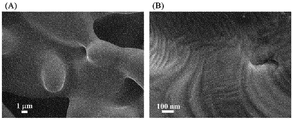
- the SEM image of the Fe 99.1 Cr 0.9 soft magnetic material (Example 1) (the numerical values in the figure are the Cr content (atomic%) in the cross portion, and is the average value in the region of radius 100 nm to 150 nm. ).
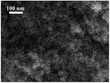
- the SEM image of the Fe 99.0 Nb 1.0 soft magnetic material (Example 25) (the numerical values in the figure are the Nb content (atomic%) in the cross portion, and is the average value in the region of radius 100 nm to 150 nm. ).
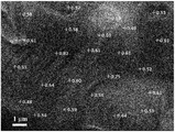
- the SEM image of the Fe 99.9 Zn 0.1 soft magnetic material (Example 46) (the numerical values in the figure are the Zn content (atomic%) in the cross portion, and is the average value in the region of radius 100 nm to 150 nm. ).
- magnetic material refers to a magnetic material referred to as “soft magnetic” (i.e., “soft magnetic material”) and a magnetic material referred to as “semi-hard magnetic material” (i.e. “semi-hard magnetic material ").
- soft magnetic material refers to a magnetic material having a coercive force of 800 A / m ( ⁇ 10 Oe) or less
- spinmi-hard magnetic material refers to a coercive force exceeding 800 A / m to 40 kA / m ( ⁇ 500 Oe) or less magnetic material.
- a semi-hard magnetic material is required to have an appropriate coercivity depending on the application and to have high saturation magnetization and residual magnetic flux density. Among them, soft magnetic or semi-hard magnetic materials for high frequency generate large eddy currents, so that the materials have high electrical resistivity, reduce the diameter of powder particles, or thin plate or strip It will be important to
- magnétique coupling refers to a state in which adjacent spins in a magnetic substance are strongly coupled by exchange interaction, and in the present invention, in particular, two adjacent crystal grains (and / or amorphous grains). ) In which the spins in the crystal are strongly connected by exchange interaction across the crystal boundary.
- grain such as crystal grains are lumps that can be recognized as being composed of one or more "phases" and separated from the three-dimensional space with a boundary.
- the exchange interaction is an interaction that extends only to the distance based on the short distance order of the material, when the nonmagnetic phase exists at the crystal boundary, the exchange interaction does not work on the spin in the regions on both sides, and the crystal grains on both sides There is no ferromagnetic coupling between (and / or amorphous particles).
- the term "crystal grain” sometimes includes amorphous grains. Further, the characteristics of the magnetic curve of the material in which ferromagnetic coupling is made between different kinds of adjacent crystal grains having different magnetic properties will be described later.
- disproportionation means that two or more kinds of phases different in composition or crystal structure are produced by chemical reaction from a phase having a homogeneous composition, and in the present invention, the homogeneous It is brought about as a result of the reduction reaction involving a reducing substance such as hydrogen involved in the composition phase.
- the chemical reaction that leads to this "disproportionation” is referred to herein as the “disproportionation reaction”, but water is often by-produced during this "disproportionation” reaction.
- M-ferrite is a material in which the Fe component of magnetite Fe 3 O 4 is substituted with M component, and the M component is Zr, Hf, V, Nb, Ta, Cr, Mo, W is one or more of W, Cu, Zn, and Si, and the M component may be simply described as M.
- the M component oxide is a substance or material in which an M component and oxygen O are bonded, and among them, one which is nonmagnetic (in the present application, also includes a case of very low magnetism).
- TM component or “TM” they refer to any one or more of Ti and Mn.
- the meaning of "contains Fe and M components” means that the magnetic material of the present invention necessarily contains Fe and M components as its components, and optionally the M component is other than the above.
- a certain amount may be replaced by an atom (specifically, one or more of Ti and Mn, which will be referred to as a TM component in the present application), and oxygen (O component) may be contained.
- O component or iron oxyhydroxide is present as a secondary phase
- H may be contained mainly as an OH group, and other unavoidable impurities, alkali metals such as K derived from the raw material, Cl, etc. It may be An alkali metal such as K is a suitable component in that it may exert an accelerating effect on the reduction reaction.
- magnetic powder generally refers to powder having magnetism, in the present application, the powder of the magnetic material of the present invention is referred to as “magnetic material powder”. Therefore, “magnetic material powder” is included in “magnetic powder”.
- the present invention relates to a magnetic material including a phase (first phase) in which the M component is contained in the ⁇ -Fe phase, and an M component-enriched phase (second phase) having an M component content higher than that phase. So, the best form is “powder” in which both phases are mixed and combined at nano level.
- These magnetic material powders are compacted as they are or sintered and used in various devices.
- it can be molded by blending an organic compound such as resin, an inorganic compound such as glass or ceramic, or a composite material thereof.
- composition, crystal structure and form, crystal grain size and powder grain size of the first phase containing Fe and M components and the second phase enriched with M components, and a method for producing them, among them A method of producing a nano-composite oxide powder to be a precursor of the magnetic material of the present invention, a method of reducing the powder, a method of solidifying the reduced powder, and a method of annealing in each step of these manufacturing methods Will be explained.
- the first phase is a crystal having a bcc structure cubic crystal (space group Im3m) containing Fe and M components as a crystal structure.
- the M component content of this phase is preferably 0.001 at% or more and 33 at% or less, assuming that the total (total content) of Fe and M components contained in the phase is 100 atomic%. That is, the composition of the first phase is expressed as Fe 100-x M x (x is 0.001 ⁇ x ⁇ 33 in atomic percentage) using the composition formula.
- the M component content or the Fe content is the sum of Fe and M components contained in the phase (in the present application, it may be referred to as the total content as described above, or the total amount). It refers to the value of the atomic ratio of M component or Fe to In the present invention, this may be expressed in atomic percent, where the total (total content) of Fe and M components contained in the phase is 100 atomic percent.
- the M component content As a property common to each of the M components, it is preferable to set the M component content to 33 atomic% or less in order to suppress the decrease in the magnetization.
- the M component content when the M component content is 20 atomic% or less, it is more preferable because magnetization exceeding 1 T can be realized depending on the manufacturing method and conditions. If the content is further 10 atomic% or less, it is particularly preferable because the saturation magnetization can be made to a magnetic material exceeding 1.6 T. Further, it is preferable to use 0.001 atomic% or more, unlike the case of Fe alone, in that adjustment of magnetic characteristics in the soft magnetic region by the effect of M component addition, for example, addition of magnetic saturation suppressing ability is possible .
- the range of the content of particularly preferable M component is 0.01 atomic percent or more and 10 atomic percent or less, and in this region, depending on the manufacturing conditions, a semi-hard magnetic material can be prepared from soft magnetic, particularly high frequency It can be a soft magnetic or semi-hard magnetic material having absorption ability, and it becomes possible to manufacture a magnetic material having more preferable electromagnetic properties. If it is desired to make the magnetization of a soft magnetic material with a higher degree of magnetization at the expense of a little coercive force, it is preferable to set the M component content of the first phase to 5 atomic% or less.
- the first phase of the Fe-M composition having this bcc structure is also referred to as the ⁇ - (Fe, M) phase in the present application, since the crystal symmetry is the same as that of the ⁇ phase which is the room temperature phase of Fe.
- the M component content of the first phase of the present invention is 100 atomic percent
- 0.001 atomic percent or more and less than 50 atomic percent of the M component is a TM component (that is, any one or more of Ti and Mn)
- the M component contained in the first phase has a composition substituted by the TM component
- the combination of M in the composition and the TM component is the above-mentioned "M component”.
- the M component content is 100 atomic%.
- adding a large number of element species to the soft magnetic material of the present invention has the effect of increasing the entropy of the magnetic material and reducing the coercivity.
- Cr is contained in the M component
- a soft magnetic material or a semi-hard magnetic material having a large saturation magnetization is obtained.
- V, Cr and Mo as the M component is effective in that the nanocrystallites of the present invention can be easily produced without largely depending on the temperature lowering rate in the reduction treatment and the annealing treatment.
- the use of Zr, Hf, Cr, V, Zn, Ta, Cu, or Si as the M component is preferable as a component of the soft magnetic material of the present invention because the anisotropic magnetic field is reduced.
- the M component When one or more of Zr, Hf, V, Nb, Ta, Mo, and W are used as the M component, the addition of 1 atomic percent or less by atomic percentage when the M component content of the first phase is 100 atomic percent However, it is possible to suppress "inappropriate grain growth" in the reduction step. It is preferable to use Cu, Zn or Si as the M component because this improves the oxidation resistance and the formability. Furthermore, when the TM component is co-added, not only the above effects but also a unique synergistic effect in which low coercivity and high magnetization are compatible may be exhibited.
- the M component is 0.01 atomic% or more and 50 atomic% depending on the TM component. Assuming that substitution is made in the range of less than 100 , the composition formula is Fe 100-x (M 100 -y TM y ) x / 100 (x, y is an atomic percentage 0.001 ⁇ x ⁇ 33, 0.001 ⁇ y ⁇ 50, M represents at least one of Zr, Hf, V, Nb, Ta, Cr, Mo, W, Cu, Zn, and Si, and TM represents at least one of Ti and Mn).
- any of the TM components addition of 0.001 atomic% or more by atomic percentage when the TM component content of the first phase is 100 atomic% is preferable from the viewpoint of the effect by the above-mentioned co-addition, 50 atomic% The addition of less than this is preferable from the viewpoint of preventing inhibition of various effects by the M component in the magnetic material of the present invention.
- 0.001 atomic% or more and less than 50 atomic% of Fe may be replaced with “coherent” with Co and / or Ni.
- the term "homogeneous" means that the content of the component in the phase is generally within a fluctuation of ⁇ 4.76% (ie, for example, in a material having a Co content of 10 atomic%, the Co content of each phase is The amount is in the range of 9.524 to 10.476 at%).
- Co coexistence not only increases the saturation magnetization but also has the effect of decreasing the coercivity.
- Ni is preferable because the addition of 5 atomic% or less improves the saturation magnetization and the substitution of 0.001 atomic% or more and less than 50 atomic% reduces the coercive force.
- mis-add means that the nano-fine structure of the magnetic material of the present invention is broken and the grains grow with a uniform crystal structure.
- “proper grain growth” in the present invention refers to disproportionation reaction after the powder particle size grows large while maintaining the nano-fine structure that is the feature of the present invention, or the powder particle size grows large. Either a nano-fine structure appears in the crystal due to phase separation or the like, or both.
- grain growth in the present invention refers to grain growth which is not “inappropriate grain growth” described above, and refers to grain growth which can be said to be generally appropriate.
- grain growth of either “proper grain growth” or “inappropriate grain growth” occurs, the surface area of the magnetic material per unit mass or per unit volume decreases, so that the oxidation resistance is generally low. Tend to improve.
- M component or “M component” or “M component” is described in a formula such as “ ⁇ - (Fe, M)” phase or in a context for discussing magnetic material composition.
- the term “sum of Fe and M components” means the sum of Fe and M components if the component other than Fe is the M component alone, and In a composition in which 0.001 to less than 50 atomic percent is replaced by a TM component, the total content of Fe, M component, and TM component is meant.
- the content thereof is 5 atomic% or less, preferably 2 atomic% or less, more preferably 0.1 atomic% or less, particularly preferably the total (that is, the sum of Fe and M components contained in the first phase). It is 0.001 atomic% or less.
- the target range may be exceeded.
- a component such as an alkali metal such as K which acts as a reducing aid when contained to some extent, and 0.001 atomic% of the whole (that is, the sum of Fe and M components contained in the first phase)
- K an alkali metal
- 0.001 atomic% of the whole that is, the sum of Fe and M components contained in the first phase
- the ⁇ -Fe phase not containing the M component is not included in the first phase or the second phase.
- the ⁇ -Fe phase not containing the M component when the content of elements other than the M component is also extremely small, saturation magnetization similar to electromagnetic soft iron is expected, but the ⁇ -Fe phase is a powder in the nano region Also, it has a poor influence on the electrical resistivity, is poor in oxidation resistance, and is poor in machinability.
- the ⁇ -Fe phase not containing the M component may be present as a separate phase as long as the object of the present invention is not impaired.
- the volume fraction of the ⁇ -Fe phase is preferably less than 50% by volume with respect to the entire magnetic material of the present invention.
- the volume fraction referred to here is the ratio of the volume occupied by the target component to the total volume of the magnetic material.
- the second phase is a phase in which the content of the M component with respect to the total of Fe and M components contained in the phase is higher than the content of the M component with respect to the total of Fe and M components contained in the first phase. It is.
- the atomic percentage of the M component to the total of Fe and M components contained in the phase is from the atomic percentage of the M component to the total of Fe and M components contained in the first phase. Is also a big phase.
- a rhombohedral M-hematite phase (typical composition is (Fe 1-u M u ) 2 O 3 phase, u depends on the kind of M component, for example, when M component is Cr, 0 ⁇ u ⁇ 1 ), Tetragonal system such as Cr 2 O 3 phase, tetragonal ⁇ -cristobalite phase (SiO 2 ), ⁇ -FeV phase, Cr 5 Si 3 phase, NbO 2 phase, etc.
- composition ratio is indicated by two figures of significant figures), etc., or a mixture thereof Can be mentioned.
- the amorphous phase, eutectic point composition phase and eutectoid point composition phase differ depending on the M component content and reduction conditions, but when an amorphous phase or the like is present It is separated from the first phase and exists as islands without taking a fine structure such as floating in the ocean of an island with microcrystals like the existing nanocrystal-amorphous phase separation type material mentioned above. There are many things to do.
- the content of the amorphous phase or the like is between 0.001 and 10% by volume, and it is preferable from the viewpoint of suppressing the decrease in the magnetization that it is not more than this, and in order to make the magnetic material of high magnetization further preferable.
- the amorphous phase or the like may be intentionally included in order to control the disproportionation reaction itself, but in this case, it is preferable to be more than 0.001% by volume from the viewpoint of exerting the reaction control effect.
- the volume fraction referred to here is the ratio of the volume occupied by the target component to the volume of the entire magnetic material.
- the second phase described above has lower saturation magnetization than the first phase, but the coexistence of these phases significantly increases the electrical resistivity. Furthermore, in the present invention, the coercivity is improved when the semi-hard magnetic material is formed. On the contrary, in the present invention, when the soft magnetic material is formed, a small coercive force can be realized by ferromagnetically coupling with the phase depending on the crystal structure, composition, microstructure, interface structure, etc. of the phase. Furthermore, also in the second phase, as in the first phase, less than 50 atomic% of the M component content (however, the content of the M component of the second phase is 100 atomic%) can be replaced with the TM component .
- the “M component” of the second phase also has a composition in which the M component contained in the second phase is substituted by the TM component as in the “M component” of the first phase described above.
- phase which contains neither Fe nor M component and is mixed only with the compound of the TM component is not included in the first phase or the second phase. However, it may contribute to the improvement of the electrical resistivity, the oxidation resistance, the sinterability, and the electromagnetic characteristics of the semi-hard magnetic material of the present invention.
- the phase which does not contain the M component such as the compound phase of the TM component and the Fe compound phase described above, and the phase in which the content of the TM component is the content of the M component element or more is referred to as "subphase" in this application.
- Phases other than the first phase and the second phase Phases other than the first phase and the second phase, w-phase which does not contain M component, M-phase (Fe 3 O 4 ), maghemite phase ( ⁇ -Fe 2 O 3 ), hematite phase ( ⁇ -Fe 2 O 3) ), Secondary phases such as ⁇ -Fe phase, ⁇ -Fe phase, and with or without M component, iron oxyhydroxide such as goethite, achagenite, lepidocrocite, ferrooxyhytite, ferrihydrite, green last etc.
- M-phase Fe 3 O 4
- maghemite phase ⁇ -Fe 2 O 3
- hematite phase ⁇ -Fe 2 O 3
- Secondary phases such as ⁇ -Fe phase, ⁇ -Fe phase, and with or without M component, iron oxyhydroxide such as goethite, achagenite, lepidocrocite, ferrooxyhytite, ferrihydrite, green
- phase hydroxide such as potassium hydroxide and sodium hydroxide, chloride such as potassium chloride and sodium chloride, fluoride, carbide, nitride, hydride, sulfide, nitrate, carbonate, sulfate, silicate And phosphates, etc., but because these volumes have high saturation magnetization, the magnetic material of the present invention also exhibits stable magnetic characteristics and high magnetization over time. First Less than the volume that is required. From the viewpoint of suppressing the decrease in saturation magnetization, the preferable range of the content of these phases is 50% by volume or less with respect to the volume of the entire magnetic material.
- the content of the TM component of all the phases including the first phase, the second phase and the subphase should not exceed the content of the M component contained in the first phase and the second phase with respect to the whole phase.
- the TM component is contained in excess of the M component content, the effect on the electromagnetic characteristics unique to the M component, for example, the reduction of the magnetocrystalline anisotropy, the improvement of the electrical resistivity, and the oxidation resistance by passivation of the powder surface It is because the peculiar feature such as improvement is lost.
- the M component content of the first phase and / or the second phase means an amount including such a TM component.
- the second phase may have the same crystal structure as the first phase, but it is desirable that the compositions be sufficiently different from each other, for example, the second phase with respect to the sum of Fe and M components in the second phase.
- the M component content of is greater than the M component content of the first phase with respect to the total of Fe and M components in the first phase, and the difference is at least 1.5 times and / or the second phase It is preferable that the M component content of the second phase is 2 atomic% or more with respect to the total of Fe and M components contained therein.
- the M component content itself of the second phase does not exceed 100 at%.
- the M component content of the second phase does not exceed 10 5 times the M component content of the first phase.
- the M component content of the second phase is preferably 90 atomic% or less of the M component content of the first phase.
- the M component content of the second phase is “1.5 times or more” of the first phase, the M component content of each phase is determined by one or more significant figures, The M component content of the second phase is 1.5 or more times the M component content of the first phase.
- the present invention aims to reduce the coercive force by utilizing the above-mentioned random magnetic anisotropy model or the fluctuation of the magnetic anisotropy according to the model, and is a crystallographically independent first phase
- the second phase are magnetically coupled by exchange coupling at the nano level, or the M component content in the bcc phase including the first phase and the second phase changes spatially at the nano scale It is important that there is a certain thing (this may be called "concentration fluctuation" in the present invention).
- the M component content of the second phase is preferably 2 atomic% or more, more preferably 5 atomic% or more, based on the total of Fe and M components in the second phase.
- the magnetocrystalline anisotropy of the two phases is reduced to half or less compared to the case where the M component is not contained. If the M component content is 8 atomic% or more, it is further preferable because the magnetocrystalline anisotropy becomes extremely small.
- phase (first phase) in which the M component content is lower than the M component content of the entire magnetic material of the present invention the phase (second phase) in which the M component content is higher than the magnetic material of the present invention is also the same In the magnetic material. Therefore, if they are ferromagnetically coupled to achieve isotropy, the magnetic material of the present invention, specifically a soft magnetic material, is obtained, and the coercive force is appropriately determined by interposing at the interface of the first phase.
- the magnetic material of the present invention specifically a semi-hard magnetic material, can be obtained if it has the function of increasing the electrical resistance as a range.
- the magnetic material of the present invention whose coercivity is lowered by such a mechanism often has a content of 10 at% or less with respect to the sum of the M component and Fe in the magnetic material.
- the above is a composition with high homogeneity, which completely removes heterophases and is not found in many existing soft magnetic materials such as electromagnetic steel sheets designed to prevent domain wall movement from being disturbed, such as Sendust. It is a feature of the material, and it can be said that magnetization reversal is a feature common to magnetic materials caused by the rotation of magnetization.
- a state in which only the first phase or only the second phase is magnetically coupled at the nano level by exchange coupling may be included, and even in this case, the crystal axis orientations of adjacent nanocrystals are not aligned. It is important that there is a nanoscale spatial distribution of M component content in the bcc phase that is isotropic or contains the first and second phase.
- a magnetic material composed of microcrystallines of only the first phase or a magnetic material composed of microcrystallines of only the second phase can not be achieved, and even when such a structure is included, In the present invention, the first phase and the second phase are always present in the magnetic material.
- nanocrystals itself is a powder of ferrite containing an M component, which is used to produce the magnetic material of the present invention, wherein the powder has a nanoscale size (herein The reason is that it is greatly involved in the disproportionation reaction in each process of the reduction process starting from the reduction of the ferrite nanopowder or the “M component—ferrite nanopowder”.
- a ferrite powder of nanoscale size is also referred to as "ferrite nanopowder”
- the nanoscale refers to a scale of 1 nm or more and less than 1 ⁇ m unless otherwise specified.
- the first phase is the ⁇ - (Fe, M component) phase, which mainly ensures high saturation magnetization.
- the second phase is a phase in which the content of the M component to the total of Fe and M components contained in the phase is larger than the content of the M component to the total of Fe and M components contained in the first phase.
- the second phase may be an ⁇ - (Fe, M component) phase which is higher than the M component content of the entire magnetic material, or may be another crystalline phase or an amorphous phase, or a mixed phase thereof.
- the soft magnetic material of the present invention has the effect of keeping the coercivity low, and even including the semi-hard magnetic material, has the effect of imparting oxidation resistance and improving the electrical resistivity. Therefore, since the second phase is an aggregate of the phases having these effects, the magnetic properties of the present invention should be able to indicate the presence of any of the previously exemplified phases, in which the content of the M component is higher than that of the first phase. It turns out that it is a material. If such a second phase does not exist and is constituted only by the first phase, any one of the magnetic properties such as the coercive force, the oxidation resistance and the electrical conductivity is inferior, and in the processability, It becomes a magnetic material which is scarce and complicates the molding process.
- the composition of the first phase and the M component may change continuously.
- the M component composition of the first phase and the second phase changes continuously.
- the M component content of the second phase (that is, the M component content in the second phase to the total of the Fe and M components contained in the second phase) is the M component content (the first phase) That is, the content of M component in the first phase is 1.5 times or more of the total of Fe and M components contained in the first phase, or the content of M component in the second phase is 2 atomic% or more It is preferable that the M component content of the first phase be greater than that of the first phase, or that the M component content of the second phase be 1.5 or more times and 2 atomic% or more of the M component content of the first phase.
- the content of M in the second phase is 1.5 times or more the content of M in the first phase, which makes it possible to adjust the electromagnetic characteristics such as the coercivity.
- the M component is mainly contained, twice or more is more preferable, and when it is twice or more also when Cr is mainly contained, a preferable range is to obtain a soft magnetic material having a small coercive force.
- composition ratio of Fe to M component is 1: 1 or less in combination of the first phase and the second phase, in other words, the content of M component is 100 atomic% with the content of Fe and M component being 100 atomic%. It is desirable that the content be 0.01 atomic percent or more and 50 atomic percent or less.
- the content of the M component in which the first phase and the second phase are combined be 50 atomic% or less in order to avoid a decrease in saturation magnetization, and that it is 0.01 atomic% or more is oxidation resistance There is no addition effect of M component to etc., and it is preferable in order to avoid that a coercive force becomes high to such an extent that it does not respond to the target application.
- the content of the M component combining the first phase and the second phase is preferably 0.05 atomic% or more and 33 atomic% or less, of which the particularly preferable range Is 0.1 atomic% or more and 25 atomic% or less.
- the volume ratio of the first phase to the second phase is arbitrary, the first phase, or the first phase and the first phase, relative to the volume of the entire magnetic material of the present invention including the first phase, the second phase and the subphase.
- the total volume of the ⁇ - (Fe, M component) phase in the second phase is preferably 5% by volume or more. Since the ⁇ - (Fe, M component) phase is responsible for the main magnetization of the magnetic material of the present invention, it is preferably 5% by volume or more in order to avoid a decrease in the magnetization. Furthermore, it is preferably 25% by volume or more, more preferably 50% by volume or more. In order to realize particularly high magnetization without significantly reducing the electrical resistivity, it is desirable to set the total volume of the ⁇ - (Fe, M component) phase to 75% by volume or more.
- a ferromagnetic or antiferromagnetic (herein, weak magnetism is also included in this phase) phase, because the crystal magnetism of the first phase is the reason It is because it has the effect of reducing anisotropy.
- the M component content of the second phase with respect to the sum of the Fe and M components in the second phase is Fe in the first phase
- the M content is higher than the first phase relative to the sum of the M and M components, and preferably, the M content is 0.1 atomic% or more to the total of Fe and M components in the second phase.
- There is an ⁇ - (Fe, M component) phase which is atomic% or less, more preferably 2 atomic% to 15 atomic%, particularly preferably 5 atomic% to 10 atomic%.
- the first phase also contains an M component content of 5 at% or more and 10 at% or less based on the total of Fe and M components in the first phase, but the M component is contained to this extent As the amount is increased, saturation magnetization close to 2T can not be exhibited. Therefore, by combining the first phase having an M component content of less than 5 atomic% and the second phase having an M component content of 5 atomic% or more, a magnetic material having a large saturation magnetization and a small coercive force is realized. Is preferred.
- preferable second phase includes M-ferrite phase and wustite phase.
- the former is ferromagnetic and the latter is antiferromagnetic, but any one can promote ferromagnetic coupling if it is between the first phase.
- These oxide phases may be nano-sized and have a very fine structure, and particularly in the wustite phase, a few atomic layers are finely dispersed in the bcc phase or layered between the bcc microcrystalline phases. It may also exist. When such an oxide layer is present, the crystal orientation of the bcc phase may be aligned in a region of several hundred nm to several tens of ⁇ m, but even in such a microstructure, the crystal grain size of the present invention, etc.
- the magnetic material of the present invention is included in the range of In particular, when the magnetic material having the above structure is a soft magnetic material, the coercivity is lowered by a mechanism slightly different from random anisotropy. It is assumed that the mechanism is as follows. Due to disproportionation, between the M component content of the first phase to the total of Fe and M components in the first phase, and the M component content of the second phase to the total of Fe and M components in the second phase If there is a difference in the density, and there is a spatially fluctuating concentration of nanoscale fine M component content, a spatial fluctuation of the magnetic anisotropy occurs, and when an external magnetic field is applied (as if It is included in the mechanism that the magnetization is switching as if the resonance phenomenon occurred.
- the above-mentioned fluctuation in concentration has the same effect of reducing the coercive force not only when the second phase is an oxide phase but also when it is an ⁇ - (Fe, M component) phase.
- ferrite phase promotes ferromagnetic coupling
- WO 2009/057742 hereinafter referred to as "patent document 1”
- N. Imaoka, Y. Koyama, etc. T. Nakao, S. Nakaoka, T. Yamaguchi, E. Kakimoto, M. Tada, T. Nakagawa, and M. Abe, J. Appl. Phys., Vol. 103, No. 7 (2008) 07E129 (hereinafter referred to as
- a ferrite phase exists between Sm 2 Fe 17 N 3 phases of a hard magnetic material, and these phases are ferromagnetically coupled to constitute an exchange spring magnet. is there.
- the present invention relates to a soft magnetic material and a semi-hard magnetic material, and the function to be exhibited is completely different from the above hard magnetic exchange spring magnet.
- the second phase which is the M-ferrite phase or the wustite phase
- mediates the exchange interaction between the first phase if such a second phase exists to surround the first phase,
- the electrical resistance is also high and the coercivity is reduced. Therefore, it is one of the highly preferable second phases particularly in the soft magnetic material of the present invention.
- the presence of a nonmagnetic M-component oxide phase in the second phase is preferable because the electrical resistance is particularly improved. Even if they exist between the first phase, they produce ferromagnetic coupling like M-ferrite phase and do not have a direct effect on the magnetic properties, but to cover the surface of these ferromagnetically coupled powders
- the presence of the M component oxide not only improves the electrical resistance and the oxidation resistance, but in some cases, may have the effect of reducing the coercive force.
- the volume fraction of the mixed oxide phase is Preferably, the total volume of the magnetic material is 95% by volume or less, more preferably 75% by volume or less, and still more preferably 50% by volume or less.
- the M-ferrite phase has lower magnetization than the ⁇ - (Fe, M) phase although it is ferromagnetic, and the wustite phase is also weakly magnetic even if it is antiferromagnetic, and although magnetization is present to some extent, the M-ferrite The magnetization is lower than that of the phase.
- the M component oxide phase is nonmagnetic.
- the magnetization of the magnetic material of the present invention becomes extremely low if it exceeds 95% by volume of the entire magnetic material in any combination of the above oxide phases, and to avoid that, 95% by volume of the entire magnetic material is avoided It is preferable to set it as the following.
- the wustite phase or M component oxide phase is the main component, the content of these three oxide phases is lower than 75% by volume, so that the magnetization is low.
- the volume% or less and when the M component oxide phase is the main component, the characteristics of the magnetic material of the present invention having high magnetization are lost when it exceeds 50 volume%. It is preferable to set it as 50 volume% or less of the whole magnetic material.
- the magnetic material is particularly high in magnetization while maintaining the electrical resistivity to a certain extent, it is preferable to set the oxide phase to 25 volume% or less.
- the preferred volume fraction is 0.001% by volume or more, particularly not very much.
- 0.01% by volume or more is more preferable, and particularly preferably 0.1% by volume or more in order to effectively improve the electrical resistivity.
- the range of the above-mentioned preferable volume fraction and the like are the same.
- the ⁇ - (Fe, M) phase, the M-ferrite phase, the wustite phase, and the M component oxide phase having an M component content higher than the first phase are exemplified.
- the three phases other than the M component oxide phase are ferromagnetic or antiferromagnetic.
- the magnetic curve is additive, so the magnetic curves of these mixed materials are simply the sum of the respective magnetic curves, and the entire magnetic material
- a smooth step on the magnetic curve of For example, when the magnetization is measured in a wide magnetic field range of 0 to 7.2 MA / m from the external magnetic field, the 1/4 major loop (from 7.2 MA / m to the zero magnetic field) of the magnetic curve of the entire magnetic material If you look at the shape of the 1 ⁇ 4 major loop) of the magnetic curve of (1), it is certain that the smooth step due to the above circumstances or the inflection point based on it is certain on the 1 ⁇ 4 major loop I can guess.
- the local compositional analysis of the metal element of the magnetic material of the present invention is mainly performed by EDX (energy dispersive X-ray spectroscopy), and the compositional analysis of the entire magnetic material is XRF (fluorescent X-ray) Elemental analysis was performed.
- EDX energy dispersive X-ray spectroscopy
- XRF fluorescent X-ray Elemental analysis
- the M component content of the first phase and the second phase is measured by an EDX apparatus attached to SEM (scanning electron microscope), FE-SEM, or TEM (transmission electron microscope) (in the present invention, this is used)
- SEM scanning electron microscope
- FE-SEM scanning electron microscope
- TEM transmission electron microscope
- the crystal structure of the first phase and the second phase is a fine structure of 300 nm or less, accurate composition analysis can not be performed by SEM or FE-SEM, but M of the magnetic material of the present invention If it is only for detecting the difference between the components and the Fe component, it can be used supplementarily. For example, to find a second phase less than 300 nm with an M component content of 5 atomic% or more, one point in the magnetic material is observed, and its quantitative value is 5 atomic% or more as an M component content. If it is confirmed that there is a tissue having an M component content of 5 atomic% or more, or a part of the tissue, within a range of 300 nm in diameter centered on that one point.
- the magnetic material in order to find the first phase in which the M component content is 2 atomic% or less, one observation in the magnetic material is performed, and the quantitative value is 2 atomic% or less as the M component content. If it is confirmed that there is a structure with a M component content of 2 atomic% or less or a part of the structure within the range of 300 nm in diameter centering on that one point.
- composition analysis is performed using an EDX apparatus attached to a TEM, for example, the electron beam can be narrowed to 0.2 nm, and very fine composition analysis can be performed.
- it is necessary to handle a large amount of data for example, 60,000 points, in order to thoroughly examine a certain area and obtain an overview of the material of the present invention. That is, in view of the composition of the magnetic material of the present invention, it is necessary to specify structural features such as the composition of the first phase and the second phase, the crystal grain size, and the like by appropriately selecting the composition distribution measuring method described above.
- the composition of the ⁇ - (Fe, M) phase can also be determined by confirming the position of the diffraction peak by means of XRD (X-ray diffractometer).
- the diffraction peaks of the ⁇ - (Fe, M) phase tend to shift to lower angles generally as the M content increases, and among them, the behavior of the (110) and (200) peaks is observed.
- ⁇ -Fe diffraction positions by referring to the method of the present invention, Fe-ferrite nanopowders containing no M component or TM component are separately prepared and compared as comparative examples
- the M component content of the Fe, M phase can also be known with one significant digit.
- the present invention is characterized by disproportionation of the M composition and the existence of various crystal phases, and it is useful to verify whether or not their crystal axes are randomly oriented. Furthermore, in order to distinguish the ⁇ - (Fe, M) phase from other oxide phases, it is convenient and effective to analyze an oxygen characteristic X-ray surface distribution map using, for example, SEM-EDX.
- each composition in the whole magnetic material in the present invention (that is, each composition in the case where the total content of components constituting the whole magnetic material is 100 atomic%) has an Fe component of 20 atomic% or more and 99.999 atomic% or less, It is preferable that the M component be in the range of 0.001 atomic% to 50 atomic%, and the O (oxygen) content be in the range of 0 atomic% to 55 atomic%, which simultaneously satisfy these. Furthermore, an alkali metal such as K may be contained at 0.0001 atomic% or more and 5 atomic% or less. It is desirable that the subphases including K and the like do not exceed 50% by volume of the whole.
- the range of 55 atomic% or less not only has a low saturation magnetization but also a first phase by reduction of the M component-ferrite nanopowder or It is preferable because disproportionation reaction to the second phase does not occur and it is possible to avoid difficulty in developing a low coercivity into a soft magnetic material.
- the magnetic material of the present invention does not necessarily contain oxygen, but in order to obtain a magnetic material having extremely high oxidation resistance and electrical resistivity, it is preferable to contain as little as possible.
- the surface of the metal powder reduced in the gradual oxidation process to be described later may be passivated, or a portion of the crystal grain boundaries of the solid magnetic material, mainly by the M component oxide, by one operation.
- the composition range in the entire magnetic material of the present invention is 20 atomic% or more and 99.998 atomic% or less of the Fe component, and 0.001 of the M component. It is desirable that the atomic percent or more and 50 atomic percent or less, and the O content be in the range of 0.001 atomic percent or more and 55 atomic percent or less.
- More preferable composition of the magnetic material of the present invention is that the Fe component is 50 atomic% or more and 99.98 atomic% or less, the M component is 0.01 atomic% or more and 49.99 atomic% or less, O is 0.01 atomic% or more and 49
- the magnetic material of the present invention which is not more than .99 atomic%, in this range, has a good balance of saturation magnetization and oxidation resistance.
- the magnetic material of the invention is preferable in that it has excellent electromagnetic properties and excellent oxidation resistance.
- the Fe component is 79.95 atomic% or more and 99.9 atomic% or less, and the M component is 0 It is preferable that the composition range is 0.05 atomic percent or more and 20 atomic percent or less, and O is 0.05 atomic percent or more and 20 atomic percent or less.
- the semi-hard magnetic material tends to contain more oxygen than the soft magnetic material in the present invention, although it can not be generally said.
- One of the present invention is a magnetic material having magnetic properties and electrical properties suitable for soft magnetic applications having a coercive force of 800 A / m or less and oxidation resistance, which will be described below.
- magnetic properties refers to the magnetization J (T), saturation magnetization J s (T), magnetic flux density (B), residual magnetic flux density B r (T), and exchange stiffness constant A (J / m) of a material.
- Magnetocrystalline anisotropy magnetic field H a (A / m), magnetocrystalline anisotropy energy E a (J / m 3 ), magnetocrystalline anisotropy constant K 1 (J / m 3 ), coercive force H cB ( A / m), intrinsic coercive force H cJ (A / m), permeability ⁇ ⁇ 0 , relative permeability ⁇ , complex permeability ⁇ r ⁇ 0 , complex relative permeability ⁇ r , its real term ⁇ ', imaginary term ⁇ And at least one of the absolute values
- the unit of “magnetic field” is a combination of A / m of SI unit system and Oe of cgs Gaussian unit system.
- oxidation resistance refers to various oxidizing atmospheres such as room temperature air. It is a time-dependent change of the above-mentioned magnetic property.
- electromagnetic properties The above magnetic properties and electrical properties are collectively referred to as "electromagnetic properties”.
- magnetization, saturation magnetization, magnetic flux density, residual magnetic flux density, and electrical resistivity are preferably higher, and for saturation magnetization, a height of 0.3 T or 30 emu / g or more is desirable, particularly soft magnetic In terms of materials, a height of 100 emu / g or more is desirable, and a height of 1.5 ⁇ m or more is desirable for the electrical resistivity.
- Other magnetic properties of the present invention such as magnetocrystalline anisotropy constant, coercivity, permeability, relative permeability, etc., are suitable depending on the application, including whether it is a semihard magnetic material or a soft magnetic material. Control.
- the permeability and the relative permeability do not necessarily have to be high depending on the application, and if the coercivity is sufficiently low and the core loss is suppressed low, for example, the relative permeability is as large as around 10 ⁇ 1 to 10 5
- the limit thickness at which the eddy current loss occurs can be increased by about 3.2 times each time the magnetic permeability is lowered by one digit.
- One of the features of the present invention is to provide a magnetization reversal mechanism mainly by direct rotation of magnetization instead of magnetization reversal due to domain wall movement, so that the coercive force is low and the eddy current loss due to domain wall movement is also small, and iron loss is suppressed low.
- a major feature of the present invention is that by using the M component of the present invention, the relative permeability can be freely controlled, for example, compared to the case where there is no M component or only the TM component.
- the magnetic saturation suppressing ability (the function or the characteristic of the magnetic material which does not cause magnetic saturation) can be given according to the above.
- Zn, Si, Cu and Ta are mentioned as M component which raises relative magnetic permeability
- Zr, Hf, V, Nb, Cr, Mo and W are mentioned as M component which lowers relative magnetic permeability.
- the reason why the permeability can be adjusted is that the magnetic material has a large electrical resistivity just by sintering as it is, so that the iron loss due to the eddy current is small, and hence the coercivity is slightly sacrificed. This is because the total iron loss can still be kept small even if the hysteresis loss is slightly increased by designing the material to suppress the magnetic permeability.
- an electric resistivity of 1.5 ⁇ m or more can be exhibited, and in a semi-hard magnetic material, an even higher electric resistivity can be exhibited.
- the saturation magnetization tends to decrease as the electrical resistivity increases. Therefore, it is necessary to determine the composition and reduction degree of the raw materials There is. In particular, less than 1000 ⁇ m is preferable to obtain the feature that the magnetization of the magnetic material of the present invention is high. Therefore, the preferred range of the electrical resistivity is 1.5 ⁇ m to 1000 ⁇ m.
- ⁇ Crystalline boundary> Whether the magnetic material of the present invention becomes soft magnetic or semi-hard magnetic depends on the magnitude of the coercivity as described above, but it is particularly closely related to its fine structure.
- the ⁇ - (Fe, M) phase may be observed in the continuous phase at first glance, but as shown in (A) and (B) of FIG. (In the present invention, heterophase interface, polycrystal grain, etc. (in the present invention, twin phase, interphase interface, polycrystal grain, etc.)
- crystals are divided not only by the boundary but also by these various crystal habits, crystal phases, intergrowth structures, dislocations, etc., their interfaces are collectively referred to as “crystal boundaries” etc. It often contains crystal boundaries as curve groups, unlike the usual linear grain boundaries, and in such a structure, there is a large difference in M component content depending on the location. Seen.
- the magnetic material of the present invention having the fine structure as described above is often a soft magnetic material.
- the first phase and the second phase start from M-ferrite nanopowder when the second phase is an ⁇ - (Fe, M) phase.
- the ⁇ - (Fe, M) phase, the first phase and the second phase have various fine structures such as crystals of gemstones such as quartz, minerals such as pyrite and meteorites, and crystals of rocks. It is held in a reduced scale, and internally contains various phases and nanocrystals with various M component contents.
- the texture that looks like grain boundaries and intergrowths also has a difference in M component content depending on the observation site, and may be a heterophase interface.
- ⁇ Random magnetic anisotropy model and mechanism of lowering coercivity unique to the present invention In the soft magnetic material of the present invention described by the random anisotropy model, it is important to satisfy the following three conditions. (1) The grain size of the ⁇ - (Fe, M) phase is small, (2) ferromagnetic coupling by exchange interaction, (3) It has random orientation. With regard to (3), it is not necessarily essential especially in a region where the content of M component of the bcc phase is 10 atomic% or less, and in this case, the lowering of the coercive force occurs on the principle different from the random anisotropy model .
- the fluctuation of the magnetic anisotropy based on the fluctuation of the concentration of the M component content on the nanoscale becomes As a result, the magnetization reversal is promoted and the coercivity is reduced.
- the magnetization reversal mechanism by this mechanism is unique to the present invention, and as far as the present inventors can know, it has been found for the first time by the present inventors.
- the grain growth occurs during reduction, when the particles are not fused so that the ferromagnetic phase continues, or when phase separation occurs such that the particles are separated.
- the first phase and the second phase are bonded directly or continuously through the metal phase or the inorganic phase. And it is desirable to make it as a mass as a whole.
- the above solidification is necessary.
- ⁇ Average grain size of first phase, second phase, entire magnetic material The average grain size of the first phase or the second phase of the soft magnetic material of the present invention, or the average grain size of the entire magnetic material is preferably 1 nm or more and less than 10 ⁇ m. When the average grain size of the first phase and the second phase is less than 10 ⁇ m, the average grain size of the entire magnetic material is also less than 10 ⁇ m.
- either the first phase or the second phase is in the nano region in order to realize the reduction of the coercive force by the above random magnetic anisotropy model or the mechanism unique to the present invention.
- both the first phase and the second phase are ferromagnetic phases, both preferably have an average crystal grain size of less than 10 ⁇ m, and less than 1 ⁇ m realizes reduction in coercive force based on a random magnetic anisotropy model.
- the thickness is 500 nm or less, and more preferably 200 nm or less because it has a remarkable reduction effect of the coercive force by the mechanism unique to the present invention although it depends on the content of the M component.
- the magnetic anisotropy energy of the first phase is often larger than that of the second phase, so in particular, if the first phase is less than 10 ⁇ m, preferably 500 nm or less, more preferably 200 nm or less
- the coercivity is extremely small, and it becomes a soft magnetic material suitable for various transformers, motors and the like.
- the thickness is less than 1 nm, the film becomes superparamagnetic at room temperature and the magnetization and the magnetic permeability may be extremely reduced. Therefore, the thickness is preferably 1 nm or more. As mentioned above, if crystal grains of less than 1 nm or an amorphous phase is present, it is required to sufficiently connect these to crystal grains of 1 nm or more by exchange interaction.
- the second phase When the second phase is not a ferromagnetic phase, the second phase does not contribute to the reduction of the coercive force by the above-described random anisotropic model or the mechanism unique to the present invention, but the presence of the second phase increases the electrical resistivity, which is a preferable component. It is.
- the first phase in order to express the coercivity contrary to the above, is maintained at an average grain size of nano level, and a suitable surface oxide layer is made the second phase, It is effective to make the second phase exist at the grain boundary of the first phase as an average crystal grain size of several nm, maintain high magnetization while expressing the coercivity of the semihard magnetic region, and impart oxidation resistance. It is.
- ⁇ Measurement of grain size> In the measurement of the crystal grain size of the present invention, an image obtained by a SEM method, a TEM method or a metallurgical microscope method is used. Within the observed range, not only the heterophase interface and the grain boundaries but also all the grain boundaries are observed, and the diameter of the crystal region in the portion surrounded by the grain boundaries is taken as the grain size. If it is difficult to see the crystal boundaries, it is better to etch the crystal boundaries using a wet method or dry etching method using a nital solution or the like.
- the average grain size is basically selected from a representative part and measured in a region including at least 100 crystal grains.
- the average crystal grain size is determined by photographing an observation area, defining an appropriate rectangular quadrilateral area on the photograph plane (enlarged projection plane to the photographing plane of the object), and applying the Jeffry method inside thereof.
- the crystal boundary width may be too small and may not be observed with respect to resolution, but in that case, the measured value of crystal grain size gives the upper limit of the actual crystal grain size. .
- the upper limit may have a crystal grain size measurement value of 10 ⁇ m.
- the magnetic material may cut the lower limit of the crystal grain size by 1 nm, for example, from phenomena such as not having a clear diffraction peak on XRD and superparamagnetism being confirmed on a magnetic curve. If indicated, the actual grain size must be determined again by TEM observation. Furthermore, in the present invention, it may be necessary to measure the crystal grain size regardless of the crystal boundary. That is, the crystal grain size of the magnetic material of the present invention having such a fine structure is the M component content, for example, when the crystal structure is finely modulated due to the fluctuation of the concentration of the M component content. The modulation width of is the grain size.
- the crystal grain size is often determined by TEM-EDX analysis or the like, but the size often corresponds approximately to the crystallite size described in the next section.
- a crystallite is a small single crystal at the microscopic level that constitutes a crystalline substance and is smaller than the individual crystals (so-called crystal grains) that constitute a polycrystal.
- the disproportionation reaction causes phase separation, and a compositional range occurs in the M component content of the bcc phase of the first phase and / or the second phase. Since the X-ray diffraction line peak position changes depending on the M component content, for example, even if the line width of the diffraction line at (200) of the bcc phase is determined and the crystallite size is determined from this, the error becomes large.
- the crystallite size obtained by this method may not be recognized as significant in the case of crystals of bcc phase structure containing an M component.
- the crystallite size obtained based on the diffraction line at (200) of the bcc phase is “apparent” as described above. It is called "crystallite size”.
- Ni and Co contained in substitution for the Fe component have an atomic radius close to that of Fe, and the degree of disproportionation is also small, and the change in crystallite size due to the composition distribution is hardly observed.
- the M component content of the bcc phase is 0.001 atomic percent or more and 1 atomic percent, the deviation of the diffraction line of (200) is very small, so within the range of 1 nm or more and 300 nm or less, the significant digit of 1 digit It is significant to measure crystallite size.
- At least the first phase is Fe 100-x M x (where x is an atomic percentage 0.001 ⁇ x ⁇ 1, M is Zr, Hf, V, Nb, Ta, Cr, Mo, W Crystals having the composition represented by the composition formula of any one or more of Cu, Zn, and Si), even when the apparent crystallite size of one significant digit is measured, substantially It can be regarded as "size". Therefore, the apparent crystallite size in such a case is simply referred to as "crystallite size" in the present application.
- the crystallite size is determined by using the (200) diffraction line width excluding the influence of the K ⁇ 2 diffraction line and the Scherrer equation, setting the dimensionless form factor to 0.9, and setting the crystallite size of the bcc phase I asked.
- the bcc phase may be at least the first phase having the phase (i.e., only the first phase has the bcc phase, or both the first phase and the second phase have the bcc phase).
- the preferred crystallite size range of the bcc phase is 1 nm or more and 300 nm or less. If it is less than 1 nm, it becomes superparamagnetic at room temperature and the magnetization and permeability may become extremely small.
- the crystallite size of the bcc phase is 200 nm or less, the coercivity enters the soft magnetic region and becomes extremely small, which is preferable because it becomes a soft magnetic material suitable for various transformers, motors and the like. Furthermore, since 100 nm or less is a region with a low M component content, not only high magnetization exceeding 2T can be obtained, but also low coercivity can be achieved simultaneously, which is a very preferable range.
- the apparent size of the crystallite size is a danger that is generally measured smaller than the “crystallite size” of a material in which the M component content of the bcc phase is 0.001 atomic% or more and 1 atomic% or less in general crystals.
- the magnetic material at least the first phase is Fe 100 -x M x (where x is an atomic percentage 0.001 ⁇ x ⁇ 33, M is Zr, Hf, V, Nb, Ta, Cr, In the crystal having a composition represented by the composition formula of any one or more of Mo, W, Cu, Zn, and Si), for example, the apparent crystallite size is in the range of 1 nm to 300 nm. If the thickness is limited to 1 nm or more and 200 nm or less, the above risk can be avoided. As a result, the relationship between crystallite size and magnetic property preferences described above is maintained. Therefore, in the magnetic material of the present invention, the “apparent crystallite size” limited to 1 nm or more and 200 nm or less is also simply referred to as “crystallite size”.
- the size of the powder of the soft magnetic material of the present invention is preferably 10 nm or more and 5 mm or less. If it is less than 10 nm, the coercivity does not become sufficiently small, and if it exceeds 5 mm, a large strain will be applied during sintering, and the coercivity will be large if there is no annealing treatment after solidification. More preferably, it is 100 nm or more and 1 mm or less, and particularly preferably 0.5 ⁇ m or more and 500 ⁇ m or less. If the average powder particle size falls within this range, it becomes a soft magnetic material with low coercivity.
- the particle size distribution is sufficiently wide within each average powder particle size range specified above, high filling can be easily achieved with a relatively small pressure, and the magnetization per volume of the solidified molded body becomes large, preferable. If the powder particle size is too large, movement of the domain wall may be excited, and the foreign phase formed by the disproportionation reaction in the process of producing the soft magnetic material of the present invention prevents movement of the domain wall, but rather The magnetic force may increase. Therefore, when molding the soft magnetic material of the present invention, it may be preferable that the surface of the magnetic material powder of the present invention having an appropriate powder particle size be in an oxidized state.
- an alloy containing an M component may form a nonmagnetic M-component oxide phase passive film on the surface by oxidation, it is not only extremely excellent in oxidation resistance, but is also reduced in coercive force and electrical resistivity. It is also effective in terms of improvement. Not only the proper gradual oxidation of the powder surface, the handling of each process in air, the reducing atmosphere, but also the solidification treatment in an inert gas atmosphere etc. are effective.
- the average particle size of the magnetic powder of the semi-hard magnetic material of the present invention is preferably in the range of 10 nm to 10 ⁇ m. If it is less than 10 nm, it is difficult to mold, and the dispersibility may be extremely poor even when dispersed and used in a synthetic resin or ceramic. Further, when the average powder particle size exceeds 10 ⁇ m, the coercive force reaches the soft magnetic region, and therefore belongs to the category of the soft magnetic material of the present invention.
- a more preferable average powder particle size is 10 nm or more and 1 ⁇ m or less, and in this range, it becomes a semi-hard magnetic material in which both saturation magnetization and coercivity are well balanced.
- the powder particle diameter of the magnetic material of the present invention is evaluated mainly by measuring the volume equivalent diameter distribution using a laser diffraction type particle size distribution analyzer and measuring the median diameter obtained from the distribution curve.
- a representative portion is selected based on a photograph obtained by a SEM method or a TEM method of powder, or a metallurgical micrograph, and a diameter of at least 100 pieces is measured and determined. Although it may be less than this, in that case, it is required that there is a part that is statistically sufficiently representative of the whole, and that the part is measured.
- priority is given to the method using SEM or TEM.
- the laser diffraction particle size distribution analyzer has priority
- the average powder particle size is determined with the above R.
- the symbol of powder particle diameter is one or two significant figures in the case of (1) or (2), and is represented by one significant figure in the case of (3).
- the powder particle size measurement method is used in combination.
- the method of (1) may result in an incorrect value even with one significant digit.
- the value of the average powder particle diameter is first obtained by the method (1), and the value is simply obtained by the method (2). It is because it is very reasonable to compare and study both and to determine the average powder particle size with the above R by obtaining.
- the average particle diameter of the powder of the magnetic material of the present invention is determined by the above method. However, if (1) and (3), or (2) and (3) do not match in single digit significant figure, measure precisely again in (1) or (2) according to the average powder particle size range.
- R must be determined.
- the classification of 500 nm and 1 mm as the standard for determining the above powder particle size measuring method may be inappropriate, etc.
- any one of the methods (1), (2) or (3) may be reselected in a limited manner without adopting the above principle.
- the magnetic material of the present invention is merely distinguished from other magnetic materials, it is sufficient if the average powder particle size is determined by one significant digit.
- a three-dimensional network in which the macroscopic powder shape contains hollow portions having many through holes It may be shaped like a sponge, so to speak. It is considered that these are formed by the fact that the grain growth proceeds by the reduction reaction and at the same time oxygen is removed from the crystal lattice to cause a large volume reduction.
- the powder particle size in this case is measured including the volume of the hollow portion inside.
- the magnetic material of the present invention is a magnetic material in which the first phase and the second phase are bonded directly or continuously via the metal phase or the inorganic phase to form a block as a whole (herein, It can also be used as "solid magnetic material". Also, as described above, when many nanocrystals are already bound in the powder, the powder may be an organic compound such as resin, an inorganic compound such as glass or ceramic, or a composite material thereof It is also possible to mix and mold.
- the packing ratio is not particularly limited as long as the object of the present invention can be achieved, but in the case of the magnetic material of the present invention having a small amount of M component, 60% by volume or more and 100% by volume or less is oxidation resistance and electricity. It is preferable because it is excellent in terms of the balance between the resistivity and the height of magnetization.
- the packing ratio referred to here is the volume of the magnetic material of the present invention relative to the volume of the entire magnetic material of the present invention including voids (that is, the magnetic material of the present invention excluding portions other than the magnetic material of the present invention.
- the percentage of the volume occupied by the material alone is expressed as a percentage.
- the more preferable range of the above-mentioned filling rate is 80% or more, and particularly preferably 90% or more.
- the magnetic material of the present invention is originally high in oxidation resistance, but the higher the filling factor, the further the oxidation resistance is increased, and not only the application range to be applied is broadened, but the saturation magnetization is improved and the performance is high. A magnetic material is obtained. Further, in the soft magnetic material of the present invention, there is also an effect that the cohesion of the powders increases and the coercivity decreases.
- magnétique material powder of the present invention is a sinterable powder material like ferrite.
- Various solid magnetic materials having a thickness of 0.5 mm or more can be easily manufactured.
- even various solid magnetic materials having a thickness of 1 mm or more and 5 mm or more can be relatively easily manufactured by sintering or the like if the thickness is 10 cm or less.
- one feature of the magnetic material of the present invention is that the electrical resistivity is high.
- the magnetic material powder of the present invention contains many crystal boundaries and various phases, while other metallic rolling materials and thin strip materials are manufactured by a manufacturing method which does not contain grain boundaries, heterophases and defects.
- the surface oxide layer of the powder before solidifying that is, the M component oxide phase present on the surface of the first phase or the second phase, wustite, magnetite, M-ferrite
- a layer having a high oxygen content such as M-hematite or amorphous, among which an oxide layer containing a large amount of M component and / or a metal layer (ie, a metal layer containing a large amount of M component), the bulk electrical resistance
- the rate also rises.
- the magnetic material of the present invention has the above-mentioned characteristics because the magnetic material of the present invention is formed by a method different from other metallic soft magnetic materials having high magnetization and high frequency application, that is, M -As we mainly provide build-up bulk magnetic materials that reduce ferrite nanopowders first to produce metal powders with nanocrystallites and then shape them into solid magnetic materials It is.
- the electrical resistance is high compared to the existing metallic soft magnetic materials represented by silicon steel, for example, the lamination process usually required when manufacturing rotating equipment etc. is considerably simplified. it can.
- the electrical resistivity of the magnetic material of the present invention is about 30 times that of silicon steel
- the thickness limit at which eddy current does not occur is about 5 times based on the relational expression (1).
- the number of stacks is also 1/5. For example, even when applied to the stator of a motor in a high rotation range of 667 Hz, the thickness is allowed up to 1.5 mm.
- the solid magnetic material of the present invention does not contain a binder such as a resin, has a high density, and can be easily processed by an ordinary processing machine into an arbitrary shape by cutting and / or plastic processing.
- a binder such as a resin
- one of the major features is that it can be easily processed into a shape such as a prismatic column, a cylinder, a ring, a disc or a flat plate, which has high industrial utility value.
- Once processed into these shapes it is also possible to cut them further and process them into a tile-like or a prism having an arbitrary base shape. That is, it is possible to easily perform cutting and / or plastic working on any shape and any form surrounded by a curved surface or a plane including a cylindrical surface.
- cutting is general metal material cutting, and it is machining with a saw, lathe, milling machine, drilling machine, grinding wheel, etc.
- plastic processing is die cutting, forming by molding, rolling, explosion, etc. Such as molding.
- annealing can be performed in the range from normal temperature to 1500 ° C. to remove distortion after cold working.
- the method for producing a magnetic material of the present invention is (1) M-ferrite nano powder production process (2) The process may include both of the reduction process, and may further include any one or more of the following processes, if necessary. (3) Step-wise oxidation step (4) Forming step (5) Annealing step Each step will be specifically described below.
- M-ferrite nano powder production process (also referred to as "process of (1)” in the present application)
- process of (1) As a preferable manufacturing process of the nano magnetic powder which is a raw material of the magnetic material of this invention, there exists a thing provided with the method synthesize
- known methods for producing ferrite fine powder include a dry bead mill method, a dry jet mill method, a plasma jet method, an arc method, an ultrasonic spray method, an iron carbonyl vapor phase decomposition method, etc. It is a preferable production method if the magnetic material of the present invention is constituted.
- non-patent document 4 page 1225
- WO 2003/015109 page 1225
- pattern 2 WO 2003/015109
- the powder surface which is the base material of plating is not utilized.
- the raw materials used for ferrite plating for example, chromium chloride and iron chloride
- this step (or method) is referred to as “M-ferrite nano powder production step” (or “M-ferrite nano powder production method”).
- M-ferrite nano powder production step or “M-ferrite nano powder production method”.
- aqueous solution previously adjusted to an acidic region is placed in a vessel (also referred to as a reaction site in the present application), and reaction is performed under ultrasonic excitation at room temperature air, with mechanical agitation at an appropriate strength or rotation number.
- the pH adjustment solution is dropped simultaneously with the solution to gradually change the solution pH from the acidic to the alkaline region to generate M-ferrite nanoparticles in the reaction site.
- the solution and the M-ferrite nanopowder are separated and dried to obtain an M-ferrite powder having an average powder particle size of 1 nm or more and less than 1000 nm (1 ⁇ m).
- the above method is mentioned as an inexpensive method because the process is simple.
- the entire process is performed at room temperature, and therefore, the manufacturing process without using this heat source reduces the burden of equipment cost and running cost.
- the method for producing the M-ferrite nanopowder used in the present invention is, of course, not limited to the above-mentioned production method, but the initial solution of the reaction site before the start of the reaction used in the above production method A description will be added below regarding the reaction solution, the reaction solution, and the pH adjusting solution.
- an acidic solution is preferable, and a solution obtained by dissolving a metal salt, a double salt thereof, a complex salt solution and the like in addition to inorganic acids such as hydrochloric acid, nitric acid, sulfuric acid and phosphoric acid in a hydrophilic solvent such as water
- a hydrophilic solvent solution such as an iron chloride solution, an M component chloride solution or the like, or an aqueous solution of an organic acid (for example, acetic acid or oxalic acid), or a combination thereof can also be used.
- Providing a reaction solution in advance as a reaction field solution is effective for efficiently advancing a synthesis reaction of M-ferrite nanopowder.
- the material for providing the reaction site may be limited, and mixing of unavoidable impurities may be permitted, so it is desirable to control between -1 and less than 7 .
- a particularly preferable pH range is 0 or more and less than 7 in order to increase the reaction efficiency in the reaction site and minimize elution and precipitation of unnecessary impurities. More preferably, it is 1 or more and less than 6.5 as a pH range in which the reaction efficiency and the yield are well balanced.
- a solvent as a reaction site a hydrophilic solvent among organic solvents and the like can also be used, but water is preferably contained so that the inorganic salt can be sufficiently ionized.
- the reaction solution is a chloride such as iron chloride or M component chloride, a nitrate such as iron nitrate, or a nitrite or sulfate containing an Fe component and / or an M component (which may optionally include a TM component) It is possible to use a solution based on water of an inorganic salt such as phosphate or fluoride, or a solution based on a hydrophilic solvent such as water based on an organic acid salt, if necessary. Also, a combination of them may be used. However, it is essential that the reaction solution contains iron ions and M component ions.
- iron ions in the reaction solution either of the cases of only divalent iron (Fe 2+ ) ions, the mixture of trivalent iron (Fe 3+ ) ions, and the case of only trivalent iron ions
- a metal ion having a divalent or less than M component element in the case of only Fe 3+ ion, it is necessary to contain a metal ion having a divalent or less than M component element.
- the valence of the M component ion in the reaction solution is typically monovalent, divalent, trivalent, tetravalent, pentavalent or hexavalent, but in the reaction solution or reaction field solution, it is divalent.
- the above hexavalent or less is particularly excellent in terms of the homogeneity of the reaction.
- aqueous solution of M component chloride (a substance in which M component and chlorine are bound, and water molecules may be contained as a hydrate like CrCl 3 )
- a commercial product which is an aqueous solution in advance may be used, but it is optional When preparing from a solid or stock solution to obtain an aqueous solution of the following concentration, there is a risk of reacting explosively when dissolved in water, so it is recommended to use a method of mixing while cooling the solution with ice cooling or the like.
- it emits hydrogen chloride when exposed to the atmosphere it is preferable to handle it in a glove box with reduced oxygen concentration.
- the M component chloride, oxychloride, etc. do not precipitate, or the component that does not dissolve remains, and even though it is colored, it is transparent. Aqueous solution is obtained.
- pH adjusting solution examples include alkaline solutions such as sodium hydroxide, potassium hydroxide, sodium carbonate, sodium hydrogencarbonate and ammonium hydroxide, acidic solutions such as hydrochloric acid, and combinations thereof. It is also possible to use a pH buffer solution such as a mixed solution of acetic acid and sodium acetate, and to add a chelate compound and the like.
- the oxidizing agent is not necessarily essential, but it is an essential component when only Fe 2+ ions are contained as Fe ions in the reaction field solution and the reaction solution.
- oxidizing agents include nitrite, nitrate, hydrogen peroxide water, chlorate, perchloric acid, hypochlorous acid, bromate, organic peroxide, dissolved oxygen water, etc., and combinations thereof Be
- inert gas such as nitrogen gas or argon gas is continuously or temporarily introduced by bubbling to the reaction site, etc., and the effect of other oxidizing agents is inhibited by limiting the oxidizing action of oxygen. It is also possible to control the reaction stably.
- M-ferrite nanoparticles proceeds by the following reaction mechanism.
- the nuclei of the M-ferrite nanoparticles are formed in the reaction solution directly or via an intermediate product such as Greenlast.
- the reaction solution contains Fe 2+ ions, which are adsorbed on the already generated powder nuclei or on the OH groups on the surface of the powder which has grown to some extent, and release H + .
- an oxidation reaction is performed by oxygen in the air, an oxidizing agent, an anodic current (e + ) or the like, a part of the adsorbed Fe 2+ ions are oxidized to Fe 3+ ions.
- Fe 2+ ion or Fe 2+ and M 3+ ion are already adsorbed. While being adsorbed again on the metal ion which has been used, and accompanied by hydrolysis, H + is released to form a ferrite phase having a spinel structure. Since OH groups are present on the surface of this ferrite phase, metal ions are adsorbed again, and the same process is repeated to grow into M-ferrite nanoparticles.
- the equilibrium curve in the pH-electrogram of Fe is such that the pH is crossed across the line separating Fe 2+ ion and ferrite.
- the reaction system should be shifted to a region where ferrite is precipitated from the stable region of (slow) Fe 2+ ion while adjusting the redox potential.
- M 3+ the reaction is trivalent from the initial stage of the reaction except in a special case, and there is almost no influence on the change of the redox potential, and in many cases the reaction due to the change of the redox potential of Fe To the ferrite solid phase) is described.
- the reaction solution is adjusted on the acid side, and the reaction field is made a basic region by adding an alkaline solution at a stretch, etc., and the particles are instantaneously formed by coprecipitation. It often occurs.
- M-ferrite nanopowder it can be considered that due to the difference in the solubility product of the Fe component and the M component, consideration is given so as not to become nonuniform.
- it since it may be prepared by this method and very small nanoparticles can be produced, it can also be used as a ferrite raw material of the magnetic material of the present invention.
- the pH adjuster is also dropped simultaneously, and the pH is gradually changed from acidic to basic.
- the process is designed so that the M component is steadily incorporated into the Fe-ferrite structure by changing it into
- H + released when ferrite is formed by the mechanism as described above is continuously introduced into the reaction site of the pH adjusting solution. As it is neutralized, the formation and growth of M-ferrite particles occur one after another.
- the M component is mixed in the last, and when this is finally converted to ferrite, the M component is incorporated in the lattice, and in the subsequent reduction reaction, it is in the first phase or the second phase. Then, the M component is incorporated into the ⁇ -Fe phase having the bcc structure.
- reaction temperature In addition to the above, other factors to control the reaction include agitation and reaction temperature.
- dispersion is very important to prevent aggregation of fine particles generated by M-ferrite nanopowder synthesis reaction and inhibition of homogeneous reaction
- a method of simultaneously performing reaction excitation while dispersing by ultrasonic waves Any of known methods depending on the purpose of reaction control, such as a method of transporting or circulating the dispersion with a pump, a method of simply stirring with a stirring spring or a rotating drum, or a method of rocking or vibrating with an actuator or the like. Or a combination thereof.
- the reaction temperature is generally from 0 to 100 ° C. from the freezing point to the boiling point of water under atmospheric pressure, since the reaction is performed in the presence of water in the method for producing M-ferrite nanopowder used in the present invention. To be elected.
- the method of synthesizing M-ferrite nanopowders in a temperature range exceeding 100 ° C. by placing the whole system under high pressure or the like produces the effects of the present invention.
- ferrite nanopowder it belongs to the magnetic material of the present invention.
- pressure and photoexcitation may be effective as a method for exciting the reaction.
- the surface of the M-ferrite nanoparticles is analyzed by EPMA to obtain an X-ray spectrum of FeL ⁇ -FeL ⁇ , and the difference between the two materials is obtained to obtain iron oxide containing Fe 2+ (eg magnetite)
- the amount of Fe 2+ ions in the M-ferrite nanoparticles can be identified by comparison with the spectra of iron oxide (for example, hematite and maghematite) standard samples only) and Fe 3+ only.
- the measurement conditions of EPMA are an acceleration voltage of 7 kV, a measurement diameter of 50 ⁇ m, a beam current of 30 nA, and a measurement time of 1 second / step.
- Typical impurity phases of M-ferrite nanopowders include oxides such as M-hematite, goethite, achagenite, lepidocrocite, ferrooxyhyrite, ferrihydrite, iron oxyhydroxide such as greenlast, water Among the hydroxides such as potassium oxide and sodium hydroxide, among which especially the ferrihydrite phase and the M-hematite phase are included, these are reduced to the ⁇ - (Fe, M) phase and other second phases after reduction. This is a phase that does not necessarily need to be removed. These ferrihydrite phase and M-hematite phase are observed as a plate-like structure having a thickness of several nm in SEM observation and the like.
- the particles have a large area in proportion to the thickness, they may promote large inappropriate grain growth in the reduction reaction process, and since there are many impurities other than Fe component, M component and oxygen, this amount is M- It is desirable that the volume fraction is smaller than that of ferrite nanopowder.
- the M component ratio of phases other than ferrihydrite and M-ferrite nanopowder centering on M-hematite is Degree of aggregation such as ferrihydrite phase (especially to avoid uneven distribution to several microns or so) because it becomes larger than M-ferrite nano powder and it is difficult to control disproportionation occurring at reduction It is desirable to be careful enough.
- the content of the ferrihydrite phase and M-ferrite phase with respect to the M component easily incorporated so as not to precipitate the inappropriate subphase not containing the M component is intended. It is also possible to co-exist in the range of 0.01% by volume to 33% by volume. This is more industrially advantageous because it is not necessary to strictly maintain the control conditions at the time of ferrite nanopowder production.
- the average powder particle size of the M-ferrite nanopowder which is a raw material of the present invention is preferably 1 nm or more and less than 1 ⁇ m (1000 nm). More preferably, it is 1 nm or more and 100 nm or less. If it is less than 1 nm, the reaction during reduction can not be sufficiently controlled, resulting in poor reproducibility. If it exceeds 100 nm, inappropriate grain growth of the metal component reduced in the reduction step becomes remarkable, and in the case of a soft magnetic material, the coercivity may increase, so 100 nm or less is preferable. Also, if it is 1 ⁇ m or more, the ⁇ -Fe phase is separated, M is not taken into this phase, and only the magnetic material having poor electromagnetic properties and oxidation resistance of the present invention may be obtained. Less than 1 ⁇ m is preferred.
- the M-ferrite nanopowder used in the present invention is mainly produced in an aqueous solution by decantation, centrifugation, filtration (in particular, suction filtration), membrane separation, distillation, vaporization, organic solvent substitution. Water is removed by solution separation by magnetic field recovery of powder, or a combination thereof. Thereafter, it is vacuum dried at normal temperature or at a high temperature of 300 ° C. or lower, or dried in air. Hot-air drying in air, inert gas such as argon gas, helium gas, nitrogen gas (however, in the present invention, nitrogen gas may not be an inert gas depending on the temperature range during heat treatment) or hydrogen It can also be dried by heat treatment in a reducing gas such as a gas or a mixed gas thereof.
- inert gas such as argon gas, helium gas, nitrogen gas (however, in the present invention, nitrogen gas may not be an inert gas depending on the temperature range during heat treatment) or hydrogen
- a reducing gas such as a gas or
- step (2) Reduction step (In the present application, it is also referred to as "step (2)")
- step (2) the M-ferrite nanopowder produced by the above method is reduced to produce the magnetic material of the present invention.
- the homogeneous cobalt ferrite nanopowder undergoes disproportionation reaction, and the magnetic material of the present invention separates into a first phase and a second phase.
- organic compound gas such as hydrogen gas, carbon monoxide gas, ammonia gas, formic acid gas and mixed gas of them and inert gas such as argon gas or helium gas And low-temperature hydrogen plasma, subcooled atomic hydrogen, etc.
- organic compound gas such as hydrogen gas, carbon monoxide gas, ammonia gas, formic acid gas and mixed gas of them and inert gas such as argon gas or helium gas And low-temperature hydrogen plasma, subcooled atomic hydrogen, etc.
- inert gas such as argon gas or helium gas
- low-temperature hydrogen plasma subcooled atomic hydrogen, etc.
- a preferable method in the production method of the present invention is a method of reducing as a reducing gas in hydrogen gas or a mixed gas thereof with an inert gas.
- the reduction with C or Ca is too strong in reducing power, and it is very difficult to control the reaction for constructing the soft magnetic material of the present invention
- There are also problems such as the generation of toxic CO after reduction and the coexistence of calcium oxide which must be removed by washing with water, but the reduction by hydrogen gas is consistently under clean conditions. It is because reduction processing can be performed.
- Fe oxide is reduced in H 2 gas flow as assumed from Ellingham diagram, but except for Cu, M component oxide is not necessarily easily obtained in H 2 gas It is understood that it is not reduced.
- H 2 / H 2 O ratio when being reduced from magnetite to metallic iron is approximately 1, whereas it is approximately 10 5 to 10 6 for SiO 2 , and H 2 It is understood that although the gas is flowing, Si oxides are unlikely to be reduced. Therefore, in a simple mixture or solid solution of Fe oxide and Si oxide, hydrogen reduction should normally be considered as ⁇ -Fe and SiO 2 .
- the M-ferrite of the present invention has a diameter of 1 nm or more and less than 1000 nm (1 ⁇ m), and the M component is atomically dispersed in a very active nanopowder, and further, the affinity between M and Fe Is alloyed as ⁇ - (Fe, M) under hydrogen gas flow.
- M oxides such as Si and V which could be substantially reduced only in the presence of Ca and C, but according to the method of the present invention, some M components are the first phase or the first phase It can be reduced to the metallic state and present as an alloy, such as in the alpha and (Fe, M) phases of the phase and the second phase.
- the present inventors estimate that the coexistence of a small amount of an alkali metal such as K also affects the promoting action of the reaction.
- the solid solution limit of M in the ⁇ - (Fe, M) phase generally increases as the temperature increases, but in the production method of the present invention, the reduction temperature is necessarily high. It can not be said that the average M component content in the ⁇ - (Fe, M) phase becomes so high. It differs depending on the kind and content of M component of the whole M-ferrite nano powder, the setting of temperature rising / falling conditions, and the kind of coexisting second phase and subphase.
- the above phenomenon is different from the conventional metal-based magnetic material manufacturing technology, and the process of reducing M-ferrite nanopowder to grow particles and then preferably sintering the powder It is also one of the features of the process of the present invention which is called built-up type.
- the oxygen content in the material of the present invention is generally determined by the inert gas melting method, but when the oxygen content before reduction is known, the weight difference between before and after reduction indicates the present invention.
- the oxygen content in the material of can be estimated.
- a halogen element such as chlorine whose content is easily changed before and after reduction, an alkali element such as K and Na, or a volatile component such as water or an organic component is contained in large amounts, In order to accurately estimate the oxygen content, it is preferable to separately identify the contents of these elements and components.
- alkali metals derived from raw materials for example, K starts to be dissipated by vaporization from inside the magnetic material at 450 ° C, and it depends on the kind and content of M component and reduction time, but most of it is 900 ° C or more It is removed. Therefore, in the initial stage of the reduction reaction, in some cases where it is undesirable for the alkali metal derived from the raw material to be retained to take advantage of its catalytic function, depending on the application, it is undesirable to remain at the product stage. By appropriate selection, the alkali metal can be appropriately removed to the finally acceptable range.
- the final range of the content of alkali metals such as K which can be easily removed while having an effective effect on reduction is such that the lower limit is 0.0001 atomic% or more and the upper limit is 5 atomic% or less
- the upper limit value can be further controlled to 1 atomic% or less, and can be 0.01 atomic% when controlled most precisely.
- the halogen element such as Cl (chlorine) remaining in the M-ferrite nanopowder is released out of the material system mainly as hydrogen halide such as HCl in a reducing atmosphere.
- Residual Cl and the like begin to decrease significantly at reduction temperatures of 450 ° C or higher, depending on the M component and K content, and changes in their contents in the reduction step, but if a reduction temperature of approximately 700 ° C or higher is selected Can be removed almost completely from the inside of the material.
- the weight loss due to the O component becoming mainly H 2 O due to transpiration is the type and content of the M component, the content of the TM component, the amount of oxygen, the amount of subphases and impurities, water
- the weight before reduction reaction is usually 100% by mass, usually between 0.1% by mass and 80% by mass.
- local oxygen content is determined based on photographs such as SEM or EDX, or phases identified by XRD or the like are observed on an image by microscopic observation such as SEM. It can also be identified. This method is suitable for estimating the oxygen content of the first phase and the second phase and the distribution thereof.
- the heat treatment in a typical reduction step raises the temperature of the material linearly or exponentially from room temperature to a constant temperature in a reducing gas flow, using one or more heating rates, and immediately performs one or two.
- the reduction temperature in the present invention refers to the highest temperature among the temperature at which the temperature raising process is switched to the temperature lowering process and the temperature in the process of maintaining the temperature for a certain period of time.
- the reduction temperature is generally 400 ° C. or more and 1500 ° C. or less, depending on the type of M component and the content of TM component. It is good to choose the temperature range.
- the magnetic material during reduction may be dissolved depending on the M component content, but the region where the M component content is usually 0.01 atomic% or more and 33 atomic% or less
- the reduction treatment can be performed by freely selecting in the temperature range of 400 ° C. or more and 1500 ° C. or less.
- the temperature of 400 ° C. or higher is preferable because the reduction rate is very slow, and the reduction time can be prevented from becoming long due to poor productivity.
- the preferable reduction temperature range is 400 ° C. or more and 1500 ° C. or less, and the more preferable reduction temperature range is 800 ° C. or more and 1200 ° C. or less.
- the M component is reduced to metal, it is caused by the coarsening of the tissue due to the reduction reaction immediately below the melting point of the magnetic material of the present invention, the reaction with a reactor such as a ceramic container, or the reduction of the reduction reaction rate due to low temperature. This is because the decrease in productivity can be avoided.
- the reduction reaction proceeds as the reduction time is longer. Therefore, as the reduction time is longer, the saturation magnetization is higher.
- the coercive force even if the reduction time is increased or the reduction temperature is increased, the coercivity is not necessarily reduced.
- the reduction time is desirably selected appropriately depending on the desired magnetic properties.
- the reduction is generally in the range of 400 ° C. or more and 1500 ° C. or less depending on the type and content of M component.
- the temperature is chosen. The reason is that if the temperature is less than 400 ° C., the reduction rate is very slow and the reduction time becomes long and the productivity is poor, and conversely, if it exceeds 1500 ° C., there is a risk of melting of Fe. This is because the features of the nanocrystals of the present invention may be inhibited and the coercivity may not be properly controlled.
- a more preferable reduction temperature range is about 450 ° C. or more and 850 ° C. or less, and a particularly preferable range is about 500 ° C. or more and 700 ° C. or less.
- the reduction temperature is preferably in the range of 400 ° C. or more and 1500 ° C. or less.
- the reduction rate is extremely slow compared to Fe-ferrite, for example, an intermediate of magnetite and maghemite (see Patent Document 1 and Non-patent Document 3).
- Fe-ferrite which does not contain an M component having an average powder particle size of 100 nm or less
- reduction to almost 100% by volume of ⁇ -Fe is carried out only by reduction in hydrogen at 450 ° C. for 1 hour. Even under the conditions of 425 ° C. and 4 hours, the Fe-ferrite is reduced to an extent not observed even by X-ray diffraction.
- such a reduction rate of M-ferrite allows reduction at high temperature, and the nano-fine structure becomes extremely coarse while M is contained in the ⁇ -Fe phase. Without disproportionation reaction, an aggregate of microcrystalline structures including the first phase and the second phase can be obtained.
- the first phase and the second phase be separated in nanoscale in the reduction step in the production thereof.
- phases of various M components and crystal structures are separated by disproportionation reaction, and their orientations are random, or M in the nano scale It is necessary that the fluctuation of the concentration of the component content be inherent, and furthermore, the respective crystal phases have to be ferromagnetically coupled.
- the reduction proceeds and grain growth of the M-ferrite nanoparticles occurs, but at that time, depending on the reduction temperature, due to the type and content of the M component of the original M-ferrite nanoparticles,
- the crystal structure and M component content of one phase and the second phase change in various ways. In the temperature range of 400 ° C. or more and 1500 ° C. or less, generally, the higher the temperature reduced to the metal phase, the higher the M component content of the first phase. Therefore, the composition of the crystal phase changes depending on the temperature rising rate in the temperature rising process and the temperature distribution in the reaction furnace.
- the second phase of the magnetic material of the present invention is Hf-ferrite and this spawn phase.
- the coercivity is high in the powder state, and is suitably used as the semi-hard magnetic material of the present invention. This is not the case when the solid magnetic material is produced by sintering or the like.
- Hf can be dissolved to some extent in the ⁇ -Fe phase at around 1100 ° C., but Hf hardly dissolves in the ⁇ -Fe phase at normal temperature.
- the Hf content in the ⁇ - (Fe, Hf) phase of the magnetic material of the present invention can exist far beyond the solid solution source which is this equilibrium composition, but these are naturally non-equilibrium phases. If it was possible to carry out an operation to lower the temperature from the reduction temperature to normal temperature over an infinite time (the temperature decrease rate is infinitesimally small), almost Hf can not coexist in the ⁇ -Fe phase. On the other hand, if it is possible to perform the operation of decreasing the temperature at an infinite rate from about 1100 ° C.
- the soft magnetic material of the present invention can not be configured by any of the above-described manufacturing methods. That is, the microstructure of the soft magnetic material of the present invention is controlled by appropriately selecting the temperature lowering rate which is not close to the above-mentioned two limits (not super gradual cooling or super quenching).
- the magnetic material of the present invention has a microstructure which is completely different from that of the bulk existing material, and does not have a composition distribution according to the equilibrium diagram at normal temperature, but at around the reduction temperature.
- a uniform phase may be generated along the equilibrium phase diagram, which extends to the nano area, in which case speed control of temperature rise and fall including the temperature rising process is important for the microstructure There is.
- optimum conditions differ depending on the target electromagnetic characteristics and the content of the M component, but usually between 0.1 ° C / min and 5000 ° C / min. It is desirable to select appropriately.
- the coercive force is low when the temperature rise / fall rate is performed at a rate of 1 ° C./min to 500 ° C./min. It is preferable because the soft magnetic material can be prepared.
- the phase separation process resulting from the “disproportionation” reaction is extremely diverse depending on the type of the M component and the conditions of the reduction process. The case where the M component is Nb will be described below.
- Figure 3 shows a SEM observation image of the reduced powder when the Nb-ferrite nanopowder having an Nb content of 1 atomic% and an average powder particle size of 100 nm or less is reduced in a hydrogen stream at 1100 ° C. or less for 1 hour. Illustrated.
- many phases with Nb content ranging from 4.0 atomic percent to 11 atomic percent from particles with Nb content of 0.6 atomic percent or less are like potato eyes. You can see the structure sticking out separately. There are also places where sprouts of about 2 atomic% are produced from the potato sprouts.
- the magnetic material of the present invention may contain an M component oxide phase as the second phase, but the presence of this phase on grain boundaries or on the surface of powder particles exerts a strong oxygen blocking effect, and the magnetic material of the present invention It greatly contributes to the improvement of the oxidation resistance of the material.
- the semi-hard magnetic material of the present invention not only makes the effect of oxidation resistance remarkable but also exerts an effect on the improvement of coercivity.
- the phase separation by disproportionation reaction during the temperature decrease mainly occurs in the ⁇ - (Fe, M) phase, and the nanoparticles and the nanostructure are precipitated, and finally, the overall nanoscale is very fine. It is considered that a disproportionation structure is constructed.
- the reduction rate in the oxide phase containing M component such as M-ferrite phase, it is also known that the higher the M component content, the slower the reduction reaction rate becomes. It is believed that eliminating them also works well for maintaining nanostructures.
- the above series of considerations are also supported by the fact that the magnetic material of the present invention usually loses its characteristics once it has melted.
- Step (3) Stepwise oxidation step (In the present application, it is also referred to as "step (3)") Since the magnetic material of the present invention after the reduction step contains nano metal particles, there is a possibility that when it is taken out to the atmosphere as it is spontaneously ignited and burned. Therefore, although not an essential step, it is preferable to carry out a gradual oxidation treatment immediately after the completion of the reduction reaction, if necessary.
- the gradual oxidation mainly oxidizes the surface of nano metal particles after reduction to passivate it as wustite, magnetite, M-ferrite, M component oxide phase, etc. to rapidly oxidize internal magnetic material bodies.
- the M component is contained as the metal component in the first phase or the first and second phases up to the reduction step.
- this M component precipitates on the alloy surface in the gradual oxidation step to form a passivated film, but it has much more oxidation resistance than a Fe magnetic material containing no M component.
- the gradual oxidation is performed, for example, in the vicinity of normal temperature to 500 ° C. in a gas containing an oxygen source such as oxygen gas, but a mixed gas containing an inert gas having a lower oxygen partial pressure than the atmosphere is often used.
- the reduction temperature and time are sufficiently long, and the grain is grown, it is stable without passing through the gradual oxidation step and being released as it is into the atmosphere.
- a passivating film may be formed, in which case no special gradual oxidation step is required. In this case, opening to the atmosphere can be regarded as a gradual oxidation process.
- the ferromagnetic coupling may be broken by the layer of the oxide layer or the passive film, so grain growth should be caused as much as possible before gradual oxidation is performed. Is preferred. If this is not the case, it is preferable to carry out the next molding step without going through the gradual oxidation step as described above, and it is desirable to continue the reduction step and the molding step by a deoxygenation or low oxygen process.
- the magnetic material of the present invention is a magnetic material in which the first phase and the second phase are bonded directly or continuously via the metal phase or the inorganic phase to form a block as a whole (ie, solid material). It is used as a magnetic material).
- the magnetic material powder of the present invention is used alone in various applications by solidifying itself or forming by adding a metal binder, other magnetic material, resin or the like.
- the first phase and the second phase are continuous either directly or through the metal phase or the inorganic phase. In this case, it functions as a solid magnetic material without undergoing the main forming process.
- sintering is performed while performing heat treatment at a temperature of 50 ° C. or higher.
- the method of sintering by heat treatment as it is without pressure application is called pressureless sintering.
- the heat treatment atmosphere is preferably a non-oxidizing atmosphere, and the heat treatment may be performed in a rare gas such as argon or helium, or in an inert gas such as nitrogen gas, or in a reducing gas containing hydrogen gas. It is also possible in the atmosphere if the temperature condition of 500 ° C. or less.
- pressureless sintering sintering may be performed not only when the pressure of the heat treatment atmosphere is normal pressure, but also in a pressurized gas phase atmosphere of 200 MPa or less or sintering in vacuum.
- the heat treatment temperature is preferably 50 ° C. or more and 1500 ° C. or less in pressure molding, and 400 ° C. or more and 1500 ° C. or less in pressureless sintering, in addition to cold forming performed at less than 50 ° C.
- the most preferable range of molding temperature is 50 ° C. or more and 1400 ° C. or less, since the material may melt at temperatures above 1400 ° C.
- This heat treatment can be carried out simultaneously with the powder compacting, and also by pressure sintering methods such as hot pressing, HIP (hot isostatic pressing), electric current sintering, and SPS (discharge plasma sintering), It is possible to mold the magnetic material of the present invention.
- pressure sintering methods such as hot pressing, HIP (hot isostatic pressing), electric current sintering, and SPS (discharge plasma sintering)
- HIP hot isostatic pressing
- electric current sintering electric current sintering
- SPS discharge plasma sintering
- the preferable range of the pressing force is 0.001 GPa or more and 2 GPa or less, more preferably 0.01 GPa or more and 1 GPa or less.
- the ultra-high pressure HP method in which the green compact is charged into a plastically deformed capsule, heat-treated and hot pressed while applying a large pressure from one to three axial directions, is unnecessary excessive. It is possible to prevent oxygen contamination.
- a hot press method that uses a uniaxial compressor and pressurized heat treatment in a cemented carbide or carbon mold, a material with a pressure of 2 GPa or more, which is difficult even with a tungsten carbide cemented carbide mold, can be used without problems such as mold breakage
- the capsule can be molded without being exposed to the atmosphere because the capsule is plastically deformed and sealed inside by pressure.
- coarse grinding, pulverizing or classification can also be performed using known methods in order to adjust the powder particle size.
- the coarse crushing is a step performed before molding, or a step performed when powdering again after molding.
- a jaw crusher hammer, stamp mill, rotor mill, pin mill, coffee mill, etc.
- the pulverization is carried out when it is necessary to pulverize the magnetic material powder after reduction or the magnetic material after molding to submicron to several tens ⁇ m.
- dry or wet pulverizers such as rotary ball mill, vibration ball mill, planetary ball mill, wet mill, jet mill, cutter mill, pin mill, automatic mortar and the like and those A combination of
- the step (3) It may be molded only in the process of 4) or the process of (4).
- M-ferrite nanopowder is prepared by the wet method exemplified in the step (1), and then reduced by the method containing hydrogen gas shown in the step (2), A step of forming by the sintering method under normal pressure or pressurization shown in the step (4) after performing gradual oxidation exposed to a low partial pressure of oxygen at normal temperature shown in the step 3), in particular (3) After the deoxidization of the surface of the material powder is performed as the step of (4), there is a manufacturing method using a step of forming in hydrogen to avoid mixing of oxygen in the additional material as the step of (4).
- the present solid magnetic material can be formed to a thickness of 0.5 mm or more, and can be processed into an arbitrary shape by cutting and / or plastic processing.
- a magnetic material powder obtained by re-pulverizing the magnetic material formed in the above step, and a magnetic material powder obtained by annealing the magnetic material powder obtained in the above step in the step (5) described later in a magnetic sheet for high frequency In the case of application to composite materials with resins such as these, compression molding is performed after mixing with a thermosetting resin or thermoplastic resin, or injection molding is performed after kneading with a thermoplastic resin, and further extrusion molding, roll It is molded by molding or calendar molding.
- a type of sheet shape for example, when applied to an electromagnetic noise absorbing sheet, a batch type sheet by compression molding with a thickness of 5 ⁇ m or more and 10000 ⁇ m, a width of 5 mm or more and 5000 mm or less, and a length of 0.005 mm or more and 1000 mm or less
- Examples include various roll-like sheets formed by molding, and cutting or forming sheets having various sizes including an A4 size.
- the magnetic material of the present invention typically has a first phase and a second phase, and one or both crystal grain sizes are in the nano range.
- Annealing for various purposes such as crystal distortion and defects occurring in each step and stabilization of a non-oxidizing active phase may be preferable as long as the object of the present invention is not impaired.
- so-called preliminary heat treatment annealing
- annealing may be performed in which a fine particle component of about several nm is heat-treated. In this case, it is preferable to anneal at about 50 ° C. to 500 ° C. in the atmosphere, in an inert gas or in vacuum.
- the coercivity of the soft magnetic material of the present invention can be reduced by removing distortions or defects of crystal lattices or microcrystals caused by volume reduction due to grain growth or reduction after the reduction step (2).
- a grinding step etc. After this step, in applications where powder is used as it is, for example, in applications such as powder magnetic cores where powder is solidified with resin or ceramic, after this step or after this step, a grinding step etc. Later, annealing under appropriate conditions may be able to improve the electromagnetic properties. In addition, in the gradual oxidation process of (3), the annealing may be useful for removing distortions and defects near the surface, the interface, and the boundary which are generated by the surface oxidation.
- Annealing after the forming step (4) is the most effective, removing distortions and defects in the crystal lattice, microstructure, etc. that occur in subsequent cutting and / or plastic working such as preforming, compression molding, hot pressing, etc. Because of this, an annealing process may be carried out actively after this process. In this process, it is also expected that the accumulated distortion, defects and the like can be alleviated at once in the process prior to that. Furthermore, after the cutting and / or plastic working described above, the steps (1) to (4), the steps (2) to (4), the steps (3) and (4), and the step (4) It is also possible to carry out annealing by putting together the strain at the same time or the strain etc. accumulated.
- the annealing atmosphere may be any in vacuum, under reduced pressure, under normal pressure, under pressure of 200 MPa or less, and as a gas species, inert gas represented by a rare gas such as argon, nitrogen gas, etc.
- a reductive gas such as hydrogen gas, or an atmosphere containing an oxygen source, such as in the air, is also possible.
- Annealing temperature is from normal temperature to 1500 ° C., and in some cases, treatment at low temperature from liquid nitrogen temperature to normal temperature is also possible.
- the apparatus for the annealing process is substantially the same as the apparatus used in the reduction process and the forming process, and can be implemented by combining known apparatuses.
- the evaluation method of the present invention is as follows.
- a cylindrical case inner diameter 2.4 mm, thickness of the powder layer is approximately 1.5 mm
- a disk-shaped compact Form a disk with a diameter of 3 mm and a thickness of about 1 mm, and draw a full loop of magnetic curve in the region of -7.2 to 7.2 MA / m with an external magnetic field using a vibrating sample magnetometer (VSM) at room temperature
- VSM vibrating sample magnetometer
- the saturation magnetization was corrected with a 5N Ni standard sample and determined by the saturation asymptotic law.
- the coercivity corrected the deviation of the magnetic field in the low magnetic field region using the paramagnetic Pd and / or Gd2O3 standard sample.
- the coercivity was also measured by the VSM method using a Helmholtz-type coil, and the validity of the above measured value was confirmed. In these measurements, after magnetization to 7.2 MA / m, if no smooth step or inflection point is found on the magnetic curve up to the zero magnetic field, the "inflection point on the 1/4 major loop" I judged it was "no".
- the saturation magnetization was converted into T (Tesla) units using the density.
- the relative magnetic permeability of the disk-shaped compact was determined using a magnetic curve whose demagnetizing factor was corrected based on the demagnetizing factor determined using a Ni standard sample having the same shape as that of the measurement sample described above.
- the direction of the measurement magnetic field is the axial direction in the case of the magnetic powder, and the radial direction in the case of the disk-shaped compact.
- the magnetic properties of the cuboid compact were measured using a direct-current magnetization measuring machine (direct-current BH loop tracer) equipped with a small single-plate measurement jig and a solid magnetic material with a sample size of 15 mm ⁇ 5 mm ⁇ 1 mm.
- a direct-current magnetization measuring machine direct-current BH loop tracer
- the magnetization in the external magnetic field 150 Oe was regarded as saturation magnetization, and the value was expressed in T (Tesla) units.
- Fe content, Co content, oxygen content, bcc- (Fe, M) phase volume fraction Fe and Co content in powder or bulk magnetic material is determined by X-ray fluorescence elemental analysis (XRF) It quantified by.
- XRF X-ray fluorescence elemental analysis
- the Fe and M component contents of the first phase and the second phase in the magnetic material were quantified by EDX attached thereto based on an image observed by FE-SEM or TEM. When the EDX measured value of a certain component is 0.00 at%, the content of that component is set to zero.
- the volume fraction of the bcc- (Fe, M) phase was quantified by image analysis by combining the method using the above-mentioned FE-SEM or TEM together with the result of the XRD method.
- the observed phase is the bcc- (Fe, M) phase or the oxide phase
- an oxygen characteristic X-ray surface distribution map using SEM-EDX or TEM-EDX is used. did. Furthermore, the value of the saturation magnetization measured in (I) also confirmed the validity of the value of the bcc- (Fe, M) phase volume fraction. The oxygen content of the magnetic material after the reduction step was also confirmed by the decrease in weight after reduction. Furthermore, image analysis by SEM-EDX was used to identify each phase. The amount of K was quantified by fluorescent X-ray elemental analysis.
- V Average powder particle size Magnetic powder was observed with a scanning electron microscope (SEM) or a transmission electron microscope (TEM) to determine the powder particle size. The part representative of the whole was selected, and the number of n was determined to be 100 or more, with one significant digit.
- SEM scanning electron microscope
- TEM transmission electron microscope
- the volume equivalent diameter distribution was measured and evaluated by the median diameter ( ⁇ m) obtained from the distribution curve. However, only when the calculated median diameter was 500 nm or more and less than 1 mm, that value was adopted, and it was confirmed that the powder particle diameter estimated by the method using the above-mentioned microscope matches the significant digit one digit.
- Example 1 and Comparative Example 1 Separately prepare an aqueous solution of a CrCl 3 ⁇ 6 H 2 O aqueous solution (chromium (III) chloride hexahydrate) and an FeCl 2 ⁇ 4 H 2 O (iron (II) chloride tetrahydrate), and mix them to obtain an aqueous solution of 25.
- a mixed aqueous solution of CrCl 3 and FeCl 2 adjusted to 1 mM was placed in a reactor to make a reaction field solution.
- This Cr-ferrite nano powder is charged in a crucible made of alumina, heated in hydrogen gas at 10 ° C./min up to 300 ° C. and held at 300 ° C. for 15 minutes, then 10 ° C./300° C. to 1100 ° C. After raising the temperature by min, reduction treatment was performed at 1100 ° C. for 1 hour. Thereafter, the temperature was lowered at 95 ° C./min up to 400 ° C., and it was allowed to cool for 40 minutes from 400 ° C. to room temperature. Subsequently, gradual oxidation treatment is performed at 20 ° C.
- Example 1 The analysis on this magnetic material was conducted by the following method, and this magnetic material was referred to as Example 1.
- this magnetic material powder was also observed by the FE-SEM / EDX method which is suitable for knowing the local Cr content of the magnetic material and the presence and degree of disproportionation (the magnification was assumed to be 10,000 times ).
- the Cr content in each phase of the present magnetic material (the numerical value in the figure is the Cr content in each phase, the atomic ratio of Cr to the total of Cr and Fe in each phase) It was found that the value is expressed by percentage) and disproportionately distributed as 0.48 atomic% or more and 0.82 atomic% or less. Note that, in FIG.
- the Cr content is also present 2.0 times a is 0.97 atomic% of ⁇ - (Fe, Cr) phase in the range of 10 5 times 1.5 times or more than its phase Te (Not shown). From the results of the entire phases measured at the above 92 points, it can be said that in this example, the Cr content is largely disproportionated and distributed in the range of 0.48 at% to 0.97 at%.
- the average value of the Cr content of these 92 phases is 0.67 atomic percent, which is lower than the 0.9 atomic percent of the Cr content which is the above-mentioned XRF measurement value, and the visual field is further increased.
- the existence of many second phases having a Cr content higher than 0.72 atomic percent, which is 1.5 times 0.48 atomic percent larger disproportionation as a whole is occurring. It is presumed that the possibility is high.
- the above result of X-ray diffraction that is, only the ⁇ - (Fe, Cr) phase which is bcc phase is clearly observed for the observed magnetic material
- FE-SEM that is, the observed magnetism In combination with the material having a crystalline phase with a Cr content of 0.48 at.% To 0.97 at.%)
- the observed magnetic material comprises an ⁇ - (Fe, Cr) phase
- an ⁇ - (Fe, Cr) phase having a Cr content higher than that of the phase was formed. If this is applied to the definitions of the first phase and the second phase described above, the former phase corresponds to the first phase, and the latter corresponds to the second phase.
- the volume fraction of the bcc phase was estimated to be 98% by volume by these image analysis, X-ray diffraction and oxygen content.
- the crystal grain sizes of the first phase and the second phase can be determined from the SEM image, and as a result of image analysis, those values were all 200 nm. .
- crystallite size of this example was 80 nm (76 nm in two significant figures).
- the saturation magnetization of this magnetic material was confirmed to exceed the magnetization 218 emu / g of ⁇ -Fe at 220.4 emu / g.
- the coercivity was 450 A / m, and there was no inflection point on the quarter major loop. Therefore, since the magnetic material of Example 1 had a coercive force of 800 A / m or less, it was also confirmed that the magnetic material of this example was a soft magnetic material.
- the average crystal grain size of the entire magnetic material was 200 nm.
- the crystal grain sizes of the first phase and the second phase were also almost the same size as the overall average grain size.
- Table 1 The measurement results of the particle size and the magnetic properties are shown in Table 1. In addition, these metal powders have the property that the magnetic characteristics are rapidly deteriorated only by leaving them in the room temperature atmosphere.
- Example 2 to 5 An Fe—Cr magnetic material was produced in the same manner as in Example 1 except that the content of the M component (Cr) was changed to the content shown in Table 1.
- the measurement results of the phase, composition, particle size and magnetic properties of this example are shown in Table 1.
- the “second phase M component content / first phase component content” in the table means “M component in the first phase when the total of Fe and M components in the first phase is 100 atomic%.
- the ratio of the content of the M component in the second phase to the total content of Fe and M components in the second phase to the content is 100 atomic%.
- an arbitrary part of the magnetic powder is photographed at a magnification of 10,000 times by the SEM, in which an area of about 12 ⁇ m ⁇ about 9 ⁇ m is targeted at a plurality of points with a beam diameter of 150 to 200 nm.
- the measurement point having the minimum M component content was determined to be the first phase
- the measurement point having the maximum M component content was determined to be the second phase.
- the case where the said ratio is 1.5 times or more and less than 2 times is described as " ⁇ 1.5"
- 2 times or more and 10 5 times or less is described as " ⁇ 2".
- the above ratio was 1.5 times or more.
- the average grain size of the first phase and the second phase matched the average grain size of the whole.
- the average grain size of the first phase and the second phase matched the average grain size of the whole.
- Example 8 to 48 and Comparative Examples 5 to 12 An Fe-M magnetic material powder was produced in the same manner as in Example 1 except that the type and content of the M component were changed as shown in Table 4.
- the M component is added as a chloride aqueous solution or hydrochloric acid solution
- the method of preparing the reaction field solution and reaction solution the method of adding the reaction solution, and the pH adjustment solution concentration differ as follows depending on the M component.
- the M component is Nb or Ta
- the reaction field solution and the reaction solution are made acidic with hydrochloric acid, and the KOH concentration of the pH adjusting solution is adjusted between 560 mM and 1 M depending on the preparation concentration.
- reaction field liquid and reaction liquid introduced the reaction field liquid into the reaction field from under Ar inert gas atmosphere using deaerated water.
- the wet reaction was performed in the presence of oxygen.
- M component is W
- a reaction solution containing Fe ions, a pH adjustment solution, and a tungsten chloride solution dissolved with concentrated hydrochloric acid were separately and simultaneously dropped to the reaction site.
- the KOH concentration of the pH adjusting solution was 700 mM.
- M component is Si
- M component was added at the time of a reduction process as a silica fine powder.
- Tables 3 to 6 The measurement results of the phase, the composition, the particle diameter, and the magnetic properties of this example are shown in Tables 3 to 6.
- the content of Nb in each phase of the present magnetic material (the numerical value in the figure is the Nb content in each phase and represents the value of the atomic ratio of Nb to the total of Nb and Fe of each phase as a percentage). It was found that the distribution was disproportionately distributed to a range of 0.13 atomic% to 10.66 atomic%.
- innumerable crystal boundaries in a curved shape curved at intervals of about 10 nm were observed also in a region seen as one ⁇ - (Fe, Nb) phase.
- Example 7 shows the results of observation of Example 46 by the FE-SEM / EDX method which is suitable to know the local Zn content of the magnetic material and the presence or degree of disproportionation.
- the content of Zn in each phase of the present magnetic material (the numerical value in the figure is the Zn content in each phase, and represents the value of the atomic ratio of Zn relative to the total of Zn and Fe of each phase as a percentage) It was found that the distribution was disproportionately distributed to 0.01 atomic percent or more and 0.25 atomic percent or less. Note that, in FIG. 7, innumerable crystal boundaries in a curved shape curved at intervals of the order of 10 nm were observed also in a region seen as one ⁇ - (Fe, Zn) phase.
- the phase can be distinguished by the Zn content, for example, the Zn content relative to the ⁇ - (Fe, Zn) phase having a Zn content of 0.01 atomic%
- the Zn content for example, the Zn content relative to the ⁇ - (Fe, Zn) phase having a Zn content of 0.01 atomic%
- the presence of a 0.25 at% ⁇ - (Fe, Zn) phase, the amount of which is greater than or equal to 1.5 and less than or equal to 10 5 times that phase, ie with respect to the ⁇ - (Fe, Zn) phase It became clear from this result that a phase corresponding to the second phase is also present in addition to the first phase.
- the part where the Zn content is observed to be 0.00 means that only Zn below the detection limit is present, so it is regarded as an ⁇ -Fe subphase and has a minimum Zn content.
- the first phase was a 0.01 at% phase.
- aqueous solutions of ZrCl 4 aqueous solution (zirconium (IV) chloride), NiCl 2 ⁇ 6 H 2 O (nickel (II) chloride hexahydrate) and FeCl 2 ⁇ 4 H 2 O (iron (II) chloride tetrahydrate)
- ZrCl 4 aqueous solution zirconium (IV) chloride
- NiCl 2 ⁇ 6 H 2 O nickel (II) chloride hexahydrate
- FeCl 2 ⁇ 4 H 2 O iron (II) chloride tetrahydrate
- aqueous potassium hydroxide solution pH adjusting solution
- 560 mM aqueous potassium hydroxide solution pH adjusting solution
- the mixture is allowed to react at the same time for 15 minutes with a mixed aqueous solution (reaction solution) of 83.8 mM ZrCl 4 , NiCl 2 and FeCl 2 added dropwise, and then the pH adjustment solution and the reaction solution are not added dropwise.
- reaction solution a mixed aqueous solution
- reaction solution 83.8 mM ZrCl 4 , NiCl 2 and FeCl 2
- the stirring was continued for another 15 minutes.
- solid components are precipitated by centrifugation, redispersed in purified water, and repeated centrifugation to adjust the pH of the supernatant solution to 9.86 and finally disperse the precipitate in ethanol, followed by centrifugation.
- a Zr-ferrite nanopowder having a composition of (Fe 0.9959 Ni 0.04 Zr 0.001 ) 43 O 57 having an average powder particle size of 20 nm. Obtained. Moreover, as a result of analyzing this nanopowder by X-ray diffraction method, it was found that the cubic Zr-ferrite phase is the main phase, and the rhombohedral ferrihydrite phase is contained as the impurity phase. .
- the Zr-ferrite nano powder is charged in a crucible made of alumina, heated in a hydrogen stream at 10 ° C./min to 300 ° C. and held at 300 ° C.
- the O content relative to the entire magnetic material was 0.9 atomic%, and the K content was zero.
- the average powder particle size of this Fe-Zr magnetic material was 20 ⁇ m.
- the analysis regarding this magnetic material was performed by the following method, and this magnetic material was used as Example 49.
- As a result of observing the obtained magnetic material by an X-ray diffraction method only the ⁇ - (Fe, Zr) phase is clearly recognized, whereby the ⁇ - (Fe, Zr) phase which is the bcc phase is the main component That was confirmed.
- “second phase M component content / first phase M component content” (the definition of which is the same as in Table 1) was “ ⁇ 2” (12 times).
- the average crystal grain size of the entire magnetic material was 200 nm.
- the crystal grain sizes of the first phase and the second phase can be determined from the SEM image, and as a result of image analysis, those values were all 200 nm. .
- the crystallite size in this example was 100 nm (95 nm in two significant figures).
- the saturation magnetization was 209.9 emu / g
- the coercivity was 430 A / m
- Example 50 In the same manner as in Example 49, a magnetic material having a composition ratio of Fe 94.6 Co 5.3 Cu 0.1 was obtained, in which the content ratio of iron, cobalt and copper is.
- the O content relative to the entire magnetic material was 0.1 atomic% or less, and the K content was also 0 atomic%.
- the ⁇ - (Fe, Cu) phase is clearly recognized, whereby the ⁇ - (Fe, Cu) phase which is the bcc phase is the main component That was confirmed.
- “second phase M component content / first phase M component content” was “ ⁇ 2” (10 times).
- the average crystal grain size of the entire magnetic material was 200 nm.
- X-ray diffraction that is, only the bcc phase ⁇ - (Fe, Cu) phase is clearly observed for the observed magnetic material
- FE-SEM FE-SEM
- the former phase corresponds to the first phase
- the latter corresponds to the second phase.
- the volume fraction of the bcc phase was estimated to be 99% by volume by these image analysis, X-ray diffraction and oxygen content.
- the crystal grain sizes of the first phase and the second phase can be determined from the SEM image, and as a result of image analysis, those values were all 200 nm. .
- the crystallite size of this example was 90 nm (87 nm for 2 significant digits).
- the saturation magnetization was 217.2 emu / g
- the coercivity was 340 A / m
- the 1/4 major loop had no inflection point. (Not shown in the table)
- Example 51 The magnetic material powder of Example 50 was charged into a tungsten carbide carbide metal mold of 3 mm ⁇ , and cold compression molding was performed in the air under the conditions of room temperature and 1 GPa. Then, the temperature of the cold-pressed compact is raised at 10 ° C./min to 300 ° C. in an argon stream, held at 300 ° C. for 15 minutes, then raised at 300 ° C. to 900 ° C. at 10 ° C./min, The temperature was immediately lowered to 400 ° C. at 75 ° C./min, and it was allowed to cool from 400 ° C. to room temperature over 40 minutes.
- a disc-shaped solid magnetic material of 3 mm ⁇ ⁇ 1 mm according to the present invention was obtained.
- the solid magnetic material had a density of 7.37 g / cm 3 , saturation magnetization and coercivity of 1.93 T and 87.55 A / m, and no inflection point on the 1 ⁇ 4 major loop. Accordingly, it was confirmed that the solid magnetic material of Example 51 is the soft magnetic material of the present invention because the coercive force is 800 A / m or less.
- the magnetic permeability of the present solid magnetic material was about 10 3 and had a very high value.
- this permeability is controlled in a wide range of 10 1 to 10 4 by the amount of added Cu (0.001 atomic percent or more and 33 atomic percent or less) and the amount of added Co (0.001 atomic percent or more and less than 50 atomic percent) I know what I can do.
- the electrical resistivity of this solid magnetic material was 1.7 ⁇ m.
- the solid magnetic material of the present invention has an electrical resistivity higher than that of 1.5 ⁇ m, which is a feature thereof, and an electric resistivity higher than that of the existing material, eg, 0.1 ⁇ m of pure iron by one digit or more. It has been found that it has an electric resistivity three to four times that of the electromagnetic steel sheet of 0.5 ⁇ m.
- Example 52 In the same manner as Comparative Example 1, a (Fe 0.959 Ni 0.040 Mn 0.001 ) 3 O 4 ferrite nanopowder was produced. To this, silica powder is mixed, and reduction reaction is performed in the same manner as in Example 1 to obtain Fe 92.0 Ni 3.9 Si 4.0 Mn 0.1 magnetic material powder with a powder particle size of 0.3 ⁇ m. I got The crystal grain size of the first phase, the second phase, and the whole was 100 nm, and the crystallite size was 30 nm. The bcc phase volume fraction was 98% or more, and the O content with respect to the entire magnetic material was 1.6 atomic%, and the K content was 0.
- Example 52 As a result of evaluating it similarly to Example 1, it turned out that fluctuation of Si composition is 1.5 times or more.
- the saturation magnetization of this magnetic material was 208.6 emu / g, the coercivity was 810 A / m, and there was no inflection point on the quarter major loop. Therefore, it was confirmed that the magnetic material of Example 52 is a semihard magnetic material because the coercivity exceeds 800 A / m and is 40 kA / m or less.
- the characteristics of the above solid magnetic materials of Examples 51 and 52 are not shown in the table.
- Example 53 The magnetic material powder of Example 52 was charged into a 15 mm ⁇ 5 mm tungsten carbide cemented carbide die, and in the same manner as in Example 51, a rectangular solid magnetic material of 15 mm ⁇ 5 mm ⁇ 1 mm was obtained.
- the solid magnetic material was evaluated in the same manner as in Example 1 by the FE-SEM / EDX method suitable for determining the local Si content of the magnetic material and the presence and degree of disproportionation, and as a result, ⁇ - ( Also in the region of the Fe, Si) phase, a phase distinguishable from the first phase ⁇ - (Fe, Si) phase by the Si content, 1.5 to 10 5 times, 2 atomic% or more and 100 or less.
- ⁇ - (Fe, Si) phase of atomic% or less is also present, that is, with respect to the ⁇ - (Fe, Si) phase, a phase corresponding to a second phase other than the first phase is also present It was revealed.
- the solid magnetic material of the present invention has a higher electrical resistivity than the characteristic 1.5 ⁇ m, and is further compared to the existing material, for example, 0.1 ⁇ m of pure iron or 0.5 ⁇ m of electromagnetic steel sheet, It has been found that it has an electrical resistivity as high as two digits. The above characteristics of this example are not shown in the table.
- Example 54 Fe 98.9 Si 1.0 Mn 0.1 magnetic material powder was produced in the same manner as in Examples 8 to 48 except that the type and content of the M component were changed. As a result of observing the obtained magnetic material by X-ray diffractometry, only the ⁇ - (Fe, Si, Mn) phase was clearly recognized. Since Si corresponds to the M component in the present application and Mn corresponds to the TM component, it was confirmed from this result that the bcc phase ⁇ - (Fe, M, TM) phase is the main component. Moreover, this magnetic material powder was also observed by the TEM / EDX method which is suitable for knowing the local Si content of the magnetic material and the presence and degree of disproportionation.
- the content of Si in each phase of the magnetic material of the present invention in which oxygen was not present was disproportionately distributed as 0.01 atomic% or more and 1.99 atomic% or less.
- the Si content is 199 times within the range of 1.5 times to 10 5 times the Si content of that phase (ie, The presence of an ⁇ - (Fe, Si, Mn) phase which is 1.99 at%, ie, corresponding to the second phase other than the first phase with respect to the ⁇ - (Fe, Si, Mn) phase It is clear from this result that the phase also exists.
- the volume fraction of the bcc phase was estimated to be 99% by volume or more by these image analysis, X-ray diffraction and oxygen content (0.6 at%).
- the crystal grain sizes of the first phase and the second phase can be determined from the characteristic X-ray image by TEM-EDX, and as a result of image analysis, those values are All were 20 to 100 nm.
- the crystallite size in this example was 30 nm. The saturation magnetization of this magnetic material was confirmed to exceed the magnetization 218 emu / g of ⁇ -Fe at 219.4 emu / g.
- the coercivity was 8 A / m, and there was no inflection point on the quarter major loop. Therefore, since the magnetic material of Example 54 had a coercive force of 800 A / m or less, it was also confirmed that the magnetic material of this example was a soft magnetic material.
- the electric resistivity of the present magnetic material is 1.5 ⁇ m or more higher than the existing general metal-based magnetic materials. From the above, it was found that according to the present magnetic powder, it is possible to solve problems such as eddy current loss.
- the first phase and the second phase in the present magnetic powders of the above Examples 1-53 are observed from the observation results by the FE-SEM / EDX method suitable for knowing the presence and the degree of disproportionation in this example.
- the phase is not derived respectively from the main raw material phase and the auxiliary raw material phase of the raw material ferrite powder, and the homogeneous raw material ferrite phase is a phase separation caused by the disproportionation reaction by the reduction reaction. all right.
- the conventional magnetic material has contradictory characteristics, high saturation magnetization, high electric resistivity, and can solve the problem of eddy current loss, and requires complicated processes such as lamination process. It is possible to provide a magnetic material having excellent electromagnetic properties combining the advantages of both metal-based materials and oxides, as well as a magnetic material having stable magnetic properties even in air.
- the present invention further includes various actuators such as transformers, heads, inductors, reactors, cores (magnetic cores), yokes, magnet switches, choke coils, noise filters, ballasts, etc. mainly used for power equipment, transformers, and information communication related equipment.
- actuators such as transformers, heads, inductors, reactors, cores (magnetic cores), yokes, magnet switches, choke coils, noise filters, ballasts, etc. mainly used for power equipment, transformers, and information communication related equipment.
- the present invention relates to a soft magnetic material used for a rotor, a stator, and the like of a motor for a home electric appliance such as a motor, an air conditioner, a refrigerator, and a vacuum cleaner.
- the present invention relates to a soft magnetic material used for sensors via a magnetic field such as an antenna, a microwave element, a magnetostrictive element, a magnetoacoustic element, a Hall element, a magnetic sensor, a current sensor, a rotation sensor, and an electronic compass.
- a magnetic field such as an antenna, a microwave element, a magnetostrictive element, a magnetoacoustic element, a Hall element, a magnetic sensor, a current sensor, a rotation sensor, and an electronic compass.
- relays such as monostable and bistable electromagnetic relays, torque limiters, relay switches, switches such as solenoid valves, rotating machines such as hysteresis motors, stabilization couplings with functions such as brakes, magnetic fields and rotational speeds etc.
- the invention relates to a semi-hard magnetic material used for magnetic recording media such as sensors, magnetic tags, biases such as spin valve elements, tape recorders, VTRs, hard disks, etc.
- high-frequency transformers and reactors as well as electromagnetic noise absorbing materials, magnetic materials that suppress obstacles due to unnecessary electromagnetic interference such as electromagnetic wave absorbing materials and magnetic shielding materials, materials for inductor elements such as inductors for noise removal, RFID (Radio Frequency Identification) It is used for soft magnetic or semi-hard magnetic materials for high frequency such as tag materials and noise filter materials.
- electromagnetic noise absorbing materials such as electromagnetic wave absorbing materials and magnetic shielding materials
- materials for inductor elements such as inductors for noise removal
- RFID Radio Frequency Identification It is used for soft magnetic or semi-hard magnetic materials for high frequency such as tag materials and noise filter materials.
Landscapes
- Chemical & Material Sciences (AREA)
- Engineering & Computer Science (AREA)
- Organic Chemistry (AREA)
- Mechanical Engineering (AREA)
- Materials Engineering (AREA)
- Metallurgy (AREA)
- Manufacturing & Machinery (AREA)
- Inorganic Chemistry (AREA)
- Power Engineering (AREA)
- Dispersion Chemistry (AREA)
- Chemical Kinetics & Catalysis (AREA)
- General Chemical & Material Sciences (AREA)
- Nanotechnology (AREA)
- Crystallography & Structural Chemistry (AREA)
- Soft Magnetic Materials (AREA)
- Powder Metallurgy (AREA)
- Hard Magnetic Materials (AREA)
Abstract
La présente invention a pour objet : un nouveau matériau magnétique qui présente une stabilité magnétique élevée et une excellente résistance à l'oxydation et qui permet d'obtenir à la fois une magnétisation de saturation considérablement plus élevée et une force coercitive inférieure par rapport à celles d'un matériau magnétique à base de ferrite classique, formé à l'aide d'un matériau magnétique obtenu par nanodispersion de phases α-(Fe,M) et de phases enrichies en constituant M (le constituant M étant au moins un constituant choisi parmi Zr, Hf, V, Nb, Ta, Cr, Mo, W, Cu, Zn et Si) ; et un procédé pour la production de celui-ci. Cette poudre de matériau magnétique présente une aptitude au moulage élevée et est telle que les phases α-(Fe, M) et les phases enrichies en M sont nanodispersées par réduction chimique de nanoparticules de M-ferrite, qui sont obtenues par synthèse en voie humide, dans de l'hydrogène et utilisation d'une séparation de phases au moyen d'une réaction de dismutation avec la mise en œuvre simultanée d'une croissance des grains. En outre, un matériau magnétique solide est obtenu par frittage de cette poudre.
Priority Applications (4)
| Application Number | Priority Date | Filing Date | Title |
|---|---|---|---|
| US16/648,836 US11459646B2 (en) | 2017-09-25 | 2018-09-20 | Magnetic material and method for producing same |
| CN201880074702.0A CN111373065B (zh) | 2017-09-25 | 2018-09-20 | 磁性材料及其制造方法 |
| EP18859752.0A EP3690071A4 (fr) | 2017-09-25 | 2018-09-20 | Matériau magnétique et procédé pour la production de celui-ci |
| JP2019543694A JP7010503B2 (ja) | 2017-09-25 | 2018-09-20 | 磁性材料とその製造方法 |
Applications Claiming Priority (4)
| Application Number | Priority Date | Filing Date | Title |
|---|---|---|---|
| JP2017-183907 | 2017-09-25 | ||
| JP2017183907 | 2017-09-25 | ||
| JP2017-222150 | 2017-11-17 | ||
| JP2017222150 | 2017-11-17 |
Publications (1)
| Publication Number | Publication Date |
|---|---|
| WO2019059259A1 true WO2019059259A1 (fr) | 2019-03-28 |
Family
ID=65811141
Family Applications (1)
| Application Number | Title | Priority Date | Filing Date |
|---|---|---|---|
| PCT/JP2018/034752 WO2019059259A1 (fr) | 2017-09-25 | 2018-09-20 | Matériau magnétique et procédé pour la production de celui-ci |
Country Status (5)
| Country | Link |
|---|---|
| US (1) | US11459646B2 (fr) |
| EP (1) | EP3690071A4 (fr) |
| JP (1) | JP7010503B2 (fr) |
| CN (1) | CN111373065B (fr) |
| WO (1) | WO2019059259A1 (fr) |
Cited By (2)
| Publication number | Priority date | Publication date | Assignee | Title |
|---|---|---|---|---|
| WO2021200746A1 (fr) * | 2020-03-31 | 2021-10-07 | パウダーテック株式会社 | Poudre de ferrite, composition de résine de ferrite, corps moulé en résine, composant électronique, équipement électronique ou boîtier d'équipement électronique |
| CN113667902A (zh) * | 2021-08-20 | 2021-11-19 | 中国矿业大学 | 高熵晶界修饰的铁基多元纳米晶合金及其制备方法 |
Families Citing this family (3)
| Publication number | Priority date | Publication date | Assignee | Title |
|---|---|---|---|---|
| CN113168955A (zh) * | 2018-11-16 | 2021-07-23 | Lg伊诺特有限公司 | 使用复合材料的磁芯 |
| DE112020000814T5 (de) * | 2019-02-15 | 2021-11-11 | Sony Group Corporation | Kobaltferrit-magnetpulver, verfahren zur herstellung desselben und magnetisches aufzeichnungsmedium |
| BR102020023390B1 (pt) * | 2020-11-16 | 2021-10-05 | Vale S.A. | Método e sistema para remoção de partículas de minério de ferro aderidas por histerese magnética a uma matriz magnética de um separador magnético vertical |
Citations (12)
| Publication number | Priority date | Publication date | Assignee | Title |
|---|---|---|---|---|
| JPH06316748A (ja) * | 1993-03-05 | 1994-11-15 | Alps Electric Co Ltd | 軟磁性合金および平面型磁気素子 |
| WO2003015109A1 (fr) | 2001-08-09 | 2003-02-20 | The Circle For The Promotion Of Science And Engineering | Substance magnetique composite formee par compression de particules metalliques revetues de ferrite et procede de preparation associe |
| JP2007070719A (ja) * | 2005-05-31 | 2007-03-22 | Mitsubishi Materials Pmg Corp | 堆積酸化膜被覆Fe−Si系鉄基軟磁性粉末およびその製造方法 |
| JP2007231331A (ja) * | 2006-02-28 | 2007-09-13 | Jfe Steel Kk | 圧粉磁心用金属粉末および圧粉磁心の製造方法 |
| WO2009057742A1 (fr) | 2007-11-02 | 2009-05-07 | Asahi Kasei Kabushiki Kaisha | Matériau magnétique composite pour aimant et procédé de fabrication de ce matériau |
| JP2010229466A (ja) * | 2009-03-26 | 2010-10-14 | Hitachi Metals Ltd | ナノ結晶軟磁性合金ならびに磁心 |
| JP2011208184A (ja) * | 2010-03-29 | 2011-10-20 | Hitachi Metals Ltd | 磁性複合粉末、およびその製造方法 |
| WO2015100244A1 (fr) * | 2013-12-26 | 2015-07-02 | Drexel University | Composites a aimantation temporaire pour moteurs electriques |
| WO2015108059A1 (fr) * | 2014-01-14 | 2015-07-23 | 日立金属株式会社 | Noyau magnétique et bobine le mettant en œuvre |
| JP2016127042A (ja) * | 2014-12-26 | 2016-07-11 | 株式会社豊田中央研究所 | 被覆処理液、圧粉磁心、磁心用粉末とその製造方法 |
| WO2017164376A1 (fr) | 2016-03-25 | 2017-09-28 | 国立研究開発法人産業技術総合研究所 | Matériau magnétique et son procédé de fabrication |
| WO2017164375A1 (fr) | 2016-03-25 | 2017-09-28 | 国立研究開発法人産業技術総合研究所 | Matériau magnétique et son procédé de fabrication |
Family Cites Families (13)
| Publication number | Priority date | Publication date | Assignee | Title |
|---|---|---|---|---|
| JPH0851010A (ja) | 1994-05-23 | 1996-02-20 | Alps Electric Co Ltd | 軟磁性合金圧密体とその製造方法および軟磁性合金圧密体形成用コーティング粉末 |
| JP4170468B2 (ja) * | 1998-09-30 | 2008-10-22 | 株式会社東芝 | 永久磁石 |
| JP2000156314A (ja) | 1998-11-20 | 2000-06-06 | Hitachi Metals Ltd | 複合磁性部材 |
| CA2598842A1 (fr) | 2005-01-25 | 2006-08-03 | Mitsubishi Materials Pmg Corporation | Poudre de fer enrobee d'oxyde contenant du magnesium |
| CN101142044B (zh) * | 2005-01-25 | 2010-12-01 | 大冶美有限公司 | 含Mg氧化膜包覆的铁粉末 |
| JP2008108760A (ja) | 2006-10-23 | 2008-05-08 | Sumitomo Electric Ind Ltd | 圧粉磁心および圧粉磁心の製造方法 |
| JP5655295B2 (ja) | 2009-11-30 | 2015-01-21 | Jfeスチール株式会社 | 低炭素鋼板およびその製造方法 |
| JP5732945B2 (ja) * | 2011-03-18 | 2015-06-10 | Tdk株式会社 | Fe−Ni系合金粉末 |
| JP5954527B2 (ja) | 2012-03-01 | 2016-07-20 | Jfeスチール株式会社 | 高周波鉄損特性に優れる極薄電磁鋼板 |
| JP6131577B2 (ja) * | 2012-11-20 | 2017-05-24 | セイコーエプソン株式会社 | 複合粒子、圧粉磁心、磁性素子および携帯型電子機器 |
| JP6191855B2 (ja) * | 2013-03-05 | 2017-09-06 | 大同特殊鋼株式会社 | 軟磁性金属粉末及び高周波用圧粉磁心 |
| JP6511832B2 (ja) * | 2014-05-14 | 2019-05-15 | Tdk株式会社 | 軟磁性金属粉末、およびその粉末を用いた軟磁性金属圧粉コア |
| JP6215163B2 (ja) * | 2014-09-19 | 2017-10-18 | 株式会社東芝 | 複合磁性材料の製造方法 |
-
2018
- 2018-09-20 US US16/648,836 patent/US11459646B2/en active Active
- 2018-09-20 CN CN201880074702.0A patent/CN111373065B/zh active Active
- 2018-09-20 WO PCT/JP2018/034752 patent/WO2019059259A1/fr active Search and Examination
- 2018-09-20 JP JP2019543694A patent/JP7010503B2/ja active Active
- 2018-09-20 EP EP18859752.0A patent/EP3690071A4/fr active Pending
Patent Citations (12)
| Publication number | Priority date | Publication date | Assignee | Title |
|---|---|---|---|---|
| JPH06316748A (ja) * | 1993-03-05 | 1994-11-15 | Alps Electric Co Ltd | 軟磁性合金および平面型磁気素子 |
| WO2003015109A1 (fr) | 2001-08-09 | 2003-02-20 | The Circle For The Promotion Of Science And Engineering | Substance magnetique composite formee par compression de particules metalliques revetues de ferrite et procede de preparation associe |
| JP2007070719A (ja) * | 2005-05-31 | 2007-03-22 | Mitsubishi Materials Pmg Corp | 堆積酸化膜被覆Fe−Si系鉄基軟磁性粉末およびその製造方法 |
| JP2007231331A (ja) * | 2006-02-28 | 2007-09-13 | Jfe Steel Kk | 圧粉磁心用金属粉末および圧粉磁心の製造方法 |
| WO2009057742A1 (fr) | 2007-11-02 | 2009-05-07 | Asahi Kasei Kabushiki Kaisha | Matériau magnétique composite pour aimant et procédé de fabrication de ce matériau |
| JP2010229466A (ja) * | 2009-03-26 | 2010-10-14 | Hitachi Metals Ltd | ナノ結晶軟磁性合金ならびに磁心 |
| JP2011208184A (ja) * | 2010-03-29 | 2011-10-20 | Hitachi Metals Ltd | 磁性複合粉末、およびその製造方法 |
| WO2015100244A1 (fr) * | 2013-12-26 | 2015-07-02 | Drexel University | Composites a aimantation temporaire pour moteurs electriques |
| WO2015108059A1 (fr) * | 2014-01-14 | 2015-07-23 | 日立金属株式会社 | Noyau magnétique et bobine le mettant en œuvre |
| JP2016127042A (ja) * | 2014-12-26 | 2016-07-11 | 株式会社豊田中央研究所 | 被覆処理液、圧粉磁心、磁心用粉末とその製造方法 |
| WO2017164376A1 (fr) | 2016-03-25 | 2017-09-28 | 国立研究開発法人産業技術総合研究所 | Matériau magnétique et son procédé de fabrication |
| WO2017164375A1 (fr) | 2016-03-25 | 2017-09-28 | 国立研究開発法人産業技術総合研究所 | Matériau magnétique et son procédé de fabrication |
Non-Patent Citations (5)
| Title |
|---|
| G. HERZER, IEEE TRANSACTIONS ON MAGNETICS, vol. 26, no. 5, 1990, pages 1397 - 1402 |
| MASAKI ABE, JOURNAL OF THE MAGNETIC SOCIETY OF JAPAN, vol. 22, no. 9, 1998, pages 1225 |
| N. IMAOKAY KOYAMAT. NAKAOS. NAKAOKAT. YAMAGUCHIE. KAKIMOTOM. TADAT. NAKAGAWAM. ABE, J. APPL. PHYS., vol. 103, no. 7, 2008 |
| See also references of EP3690071A4 |
| Y ZHANGP. SHARMAA. MAKINO, AIP ADVANCES, vol. 3, no. 6, 2013, pages 062118 |
Cited By (2)
| Publication number | Priority date | Publication date | Assignee | Title |
|---|---|---|---|---|
| WO2021200746A1 (fr) * | 2020-03-31 | 2021-10-07 | パウダーテック株式会社 | Poudre de ferrite, composition de résine de ferrite, corps moulé en résine, composant électronique, équipement électronique ou boîtier d'équipement électronique |
| CN113667902A (zh) * | 2021-08-20 | 2021-11-19 | 中国矿业大学 | 高熵晶界修饰的铁基多元纳米晶合金及其制备方法 |
Also Published As
| Publication number | Publication date |
|---|---|
| JP7010503B2 (ja) | 2022-01-26 |
| EP3690071A4 (fr) | 2021-07-14 |
| CN111373065A (zh) | 2020-07-03 |
| US20200248288A1 (en) | 2020-08-06 |
| US11459646B2 (en) | 2022-10-04 |
| CN111373065B (zh) | 2021-11-23 |
| EP3690071A1 (fr) | 2020-08-05 |
| JPWO2019059259A1 (ja) | 2021-02-04 |
Similar Documents
| Publication | Publication Date | Title |
|---|---|---|
| JP6521416B2 (ja) | 磁性材料とその製造法 | |
| US11732336B2 (en) | Magnetic material and method for producing same | |
| JP6521415B2 (ja) | 磁性材料とその製造方法 | |
| US11459646B2 (en) | Magnetic material and method for producing same | |
| JP6942343B2 (ja) | 磁性材料およびその製造方法 | |
| JP4830024B2 (ja) | 磁石用複合磁性材料、及びその製造方法 | |
| JP4680272B2 (ja) | 異方性磁性材料の製造方法および異方性磁性材料 | |
| US11331721B2 (en) | Magnetic material and process for manufacturing same | |
| JP7001259B2 (ja) | 磁性材料およびその製造法 |
Legal Events
| Date | Code | Title | Description |
|---|---|---|---|
| 121 | Ep: the epo has been informed by wipo that ep was designated in this application |
Ref document number: 18859752 Country of ref document: EP Kind code of ref document: A1 |
|
| DPE1 | Request for preliminary examination filed after expiration of 19th month from priority date (pct application filed from 20040101) | ||
| ENP | Entry into the national phase |
Ref document number: 2019543694 Country of ref document: JP Kind code of ref document: A |
|
| NENP | Non-entry into the national phase |
Ref country code: DE |
|
| ENP | Entry into the national phase |
Ref document number: 2018859752 Country of ref document: EP Effective date: 20200428 |