WO2019059259A1 - Magnetic material and method for producing same - Google Patents
Magnetic material and method for producing same Download PDFInfo
- Publication number
- WO2019059259A1 WO2019059259A1 PCT/JP2018/034752 JP2018034752W WO2019059259A1 WO 2019059259 A1 WO2019059259 A1 WO 2019059259A1 JP 2018034752 W JP2018034752 W JP 2018034752W WO 2019059259 A1 WO2019059259 A1 WO 2019059259A1
- Authority
- WO
- WIPO (PCT)
- Prior art keywords
- phase
- magnetic material
- component
- atomic
- content
- Prior art date
Links
Images


Classifications
-
- C—CHEMISTRY; METALLURGY
- C22—METALLURGY; FERROUS OR NON-FERROUS ALLOYS; TREATMENT OF ALLOYS OR NON-FERROUS METALS
- C22C—ALLOYS
- C22C33/00—Making ferrous alloys
- C22C33/02—Making ferrous alloys by powder metallurgy
- C22C33/0235—Starting from compounds, e.g. oxides
-
- B—PERFORMING OPERATIONS; TRANSPORTING
- B22—CASTING; POWDER METALLURGY
- B22F—WORKING METALLIC POWDER; MANUFACTURE OF ARTICLES FROM METALLIC POWDER; MAKING METALLIC POWDER; APPARATUS OR DEVICES SPECIALLY ADAPTED FOR METALLIC POWDER
- B22F1/00—Metallic powder; Treatment of metallic powder, e.g. to facilitate working or to improve properties
- B22F1/05—Metallic powder characterised by the size or surface area of the particles
-
- B—PERFORMING OPERATIONS; TRANSPORTING
- B22—CASTING; POWDER METALLURGY
- B22F—WORKING METALLIC POWDER; MANUFACTURE OF ARTICLES FROM METALLIC POWDER; MAKING METALLIC POWDER; APPARATUS OR DEVICES SPECIALLY ADAPTED FOR METALLIC POWDER
- B22F1/00—Metallic powder; Treatment of metallic powder, e.g. to facilitate working or to improve properties
- B22F1/07—Metallic powder characterised by particles having a nanoscale microstructure
-
- B—PERFORMING OPERATIONS; TRANSPORTING
- B22—CASTING; POWDER METALLURGY
- B22F—WORKING METALLIC POWDER; MANUFACTURE OF ARTICLES FROM METALLIC POWDER; MAKING METALLIC POWDER; APPARATUS OR DEVICES SPECIALLY ADAPTED FOR METALLIC POWDER
- B22F3/00—Manufacture of workpieces or articles from metallic powder characterised by the manner of compacting or sintering; Apparatus specially adapted therefor ; Presses and furnaces
-
- B—PERFORMING OPERATIONS; TRANSPORTING
- B22—CASTING; POWDER METALLURGY
- B22F—WORKING METALLIC POWDER; MANUFACTURE OF ARTICLES FROM METALLIC POWDER; MAKING METALLIC POWDER; APPARATUS OR DEVICES SPECIALLY ADAPTED FOR METALLIC POWDER
- B22F5/00—Manufacture of workpieces or articles from metallic powder characterised by the special shape of the product
-
- B—PERFORMING OPERATIONS; TRANSPORTING
- B22—CASTING; POWDER METALLURGY
- B22F—WORKING METALLIC POWDER; MANUFACTURE OF ARTICLES FROM METALLIC POWDER; MAKING METALLIC POWDER; APPARATUS OR DEVICES SPECIALLY ADAPTED FOR METALLIC POWDER
- B22F9/00—Making metallic powder or suspensions thereof
- B22F9/16—Making metallic powder or suspensions thereof using chemical processes
- B22F9/18—Making metallic powder or suspensions thereof using chemical processes with reduction of metal compounds
- B22F9/20—Making metallic powder or suspensions thereof using chemical processes with reduction of metal compounds starting from solid metal compounds
- B22F9/22—Making metallic powder or suspensions thereof using chemical processes with reduction of metal compounds starting from solid metal compounds using gaseous reductors
-
- C—CHEMISTRY; METALLURGY
- C01—INORGANIC CHEMISTRY
- C01G—COMPOUNDS CONTAINING METALS NOT COVERED BY SUBCLASSES C01D OR C01F
- C01G49/00—Compounds of iron
-
- C—CHEMISTRY; METALLURGY
- C01—INORGANIC CHEMISTRY
- C01G—COMPOUNDS CONTAINING METALS NOT COVERED BY SUBCLASSES C01D OR C01F
- C01G51/00—Compounds of cobalt
-
- C—CHEMISTRY; METALLURGY
- C01—INORGANIC CHEMISTRY
- C01G—COMPOUNDS CONTAINING METALS NOT COVERED BY SUBCLASSES C01D OR C01F
- C01G53/00—Compounds of nickel
-
- C—CHEMISTRY; METALLURGY
- C22—METALLURGY; FERROUS OR NON-FERROUS ALLOYS; TREATMENT OF ALLOYS OR NON-FERROUS METALS
- C22C—ALLOYS
- C22C33/00—Making ferrous alloys
- C22C33/02—Making ferrous alloys by powder metallurgy
- C22C33/0257—Making ferrous alloys by powder metallurgy characterised by the range of the alloying elements
-
- C—CHEMISTRY; METALLURGY
- C22—METALLURGY; FERROUS OR NON-FERROUS ALLOYS; TREATMENT OF ALLOYS OR NON-FERROUS METALS
- C22C—ALLOYS
- C22C38/00—Ferrous alloys, e.g. steel alloys
-
- C—CHEMISTRY; METALLURGY
- C22—METALLURGY; FERROUS OR NON-FERROUS ALLOYS; TREATMENT OF ALLOYS OR NON-FERROUS METALS
- C22C—ALLOYS
- C22C38/00—Ferrous alloys, e.g. steel alloys
- C22C38/02—Ferrous alloys, e.g. steel alloys containing silicon
-
- C—CHEMISTRY; METALLURGY
- C22—METALLURGY; FERROUS OR NON-FERROUS ALLOYS; TREATMENT OF ALLOYS OR NON-FERROUS METALS
- C22C—ALLOYS
- C22C38/00—Ferrous alloys, e.g. steel alloys
- C22C38/04—Ferrous alloys, e.g. steel alloys containing manganese
-
- C—CHEMISTRY; METALLURGY
- C22—METALLURGY; FERROUS OR NON-FERROUS ALLOYS; TREATMENT OF ALLOYS OR NON-FERROUS METALS
- C22C—ALLOYS
- C22C38/00—Ferrous alloys, e.g. steel alloys
- C22C38/08—Ferrous alloys, e.g. steel alloys containing nickel
-
- C—CHEMISTRY; METALLURGY
- C22—METALLURGY; FERROUS OR NON-FERROUS ALLOYS; TREATMENT OF ALLOYS OR NON-FERROUS METALS
- C22C—ALLOYS
- C22C38/00—Ferrous alloys, e.g. steel alloys
- C22C38/10—Ferrous alloys, e.g. steel alloys containing cobalt
-
- C—CHEMISTRY; METALLURGY
- C22—METALLURGY; FERROUS OR NON-FERROUS ALLOYS; TREATMENT OF ALLOYS OR NON-FERROUS METALS
- C22C—ALLOYS
- C22C38/00—Ferrous alloys, e.g. steel alloys
- C22C38/16—Ferrous alloys, e.g. steel alloys containing copper
-
- H—ELECTRICITY
- H01—ELECTRIC ELEMENTS
- H01F—MAGNETS; INDUCTANCES; TRANSFORMERS; SELECTION OF MATERIALS FOR THEIR MAGNETIC PROPERTIES
- H01F1/00—Magnets or magnetic bodies characterised by the magnetic materials therefor; Selection of materials for their magnetic properties
- H01F1/01—Magnets or magnetic bodies characterised by the magnetic materials therefor; Selection of materials for their magnetic properties of inorganic materials
- H01F1/03—Magnets or magnetic bodies characterised by the magnetic materials therefor; Selection of materials for their magnetic properties of inorganic materials characterised by their coercivity
- H01F1/12—Magnets or magnetic bodies characterised by the magnetic materials therefor; Selection of materials for their magnetic properties of inorganic materials characterised by their coercivity of soft-magnetic materials
- H01F1/34—Magnets or magnetic bodies characterised by the magnetic materials therefor; Selection of materials for their magnetic properties of inorganic materials characterised by their coercivity of soft-magnetic materials non-metallic substances, e.g. ferrites
- H01F1/342—Oxides
- H01F1/344—Ferrites, e.g. having a cubic spinel structure (X2+O)(Y23+O3), e.g. magnetite Fe3O4
-
- H—ELECTRICITY
- H01—ELECTRIC ELEMENTS
- H01F—MAGNETS; INDUCTANCES; TRANSFORMERS; SELECTION OF MATERIALS FOR THEIR MAGNETIC PROPERTIES
- H01F1/00—Magnets or magnetic bodies characterised by the magnetic materials therefor; Selection of materials for their magnetic properties
- H01F1/01—Magnets or magnetic bodies characterised by the magnetic materials therefor; Selection of materials for their magnetic properties of inorganic materials
- H01F1/03—Magnets or magnetic bodies characterised by the magnetic materials therefor; Selection of materials for their magnetic properties of inorganic materials characterised by their coercivity
- H01F1/12—Magnets or magnetic bodies characterised by the magnetic materials therefor; Selection of materials for their magnetic properties of inorganic materials characterised by their coercivity of soft-magnetic materials
- H01F1/34—Magnets or magnetic bodies characterised by the magnetic materials therefor; Selection of materials for their magnetic properties of inorganic materials characterised by their coercivity of soft-magnetic materials non-metallic substances, e.g. ferrites
- H01F1/36—Magnets or magnetic bodies characterised by the magnetic materials therefor; Selection of materials for their magnetic properties of inorganic materials characterised by their coercivity of soft-magnetic materials non-metallic substances, e.g. ferrites in the form of particles
-
- B—PERFORMING OPERATIONS; TRANSPORTING
- B22—CASTING; POWDER METALLURGY
- B22F—WORKING METALLIC POWDER; MANUFACTURE OF ARTICLES FROM METALLIC POWDER; MAKING METALLIC POWDER; APPARATUS OR DEVICES SPECIALLY ADAPTED FOR METALLIC POWDER
- B22F1/00—Metallic powder; Treatment of metallic powder, e.g. to facilitate working or to improve properties
- B22F1/08—Metallic powder characterised by particles having an amorphous microstructure
-
- B—PERFORMING OPERATIONS; TRANSPORTING
- B22—CASTING; POWDER METALLURGY
- B22F—WORKING METALLIC POWDER; MANUFACTURE OF ARTICLES FROM METALLIC POWDER; MAKING METALLIC POWDER; APPARATUS OR DEVICES SPECIALLY ADAPTED FOR METALLIC POWDER
- B22F2207/00—Aspects of the compositions, gradients
- B22F2207/01—Composition gradients
-
- B—PERFORMING OPERATIONS; TRANSPORTING
- B22—CASTING; POWDER METALLURGY
- B22F—WORKING METALLIC POWDER; MANUFACTURE OF ARTICLES FROM METALLIC POWDER; MAKING METALLIC POWDER; APPARATUS OR DEVICES SPECIALLY ADAPTED FOR METALLIC POWDER
- B22F2301/00—Metallic composition of the powder or its coating
- B22F2301/35—Iron
-
- B—PERFORMING OPERATIONS; TRANSPORTING
- B22—CASTING; POWDER METALLURGY
- B22F—WORKING METALLIC POWDER; MANUFACTURE OF ARTICLES FROM METALLIC POWDER; MAKING METALLIC POWDER; APPARATUS OR DEVICES SPECIALLY ADAPTED FOR METALLIC POWDER
- B22F2998/00—Supplementary information concerning processes or compositions relating to powder metallurgy
- B22F2998/10—Processes characterised by the sequence of their steps
-
- B—PERFORMING OPERATIONS; TRANSPORTING
- B22—CASTING; POWDER METALLURGY
- B22F—WORKING METALLIC POWDER; MANUFACTURE OF ARTICLES FROM METALLIC POWDER; MAKING METALLIC POWDER; APPARATUS OR DEVICES SPECIALLY ADAPTED FOR METALLIC POWDER
- B22F2999/00—Aspects linked to processes or compositions used in powder metallurgy
-
- C—CHEMISTRY; METALLURGY
- C22—METALLURGY; FERROUS OR NON-FERROUS ALLOYS; TREATMENT OF ALLOYS OR NON-FERROUS METALS
- C22C—ALLOYS
- C22C2200/00—Crystalline structure
- C22C2200/04—Nanocrystalline
-
- C—CHEMISTRY; METALLURGY
- C22—METALLURGY; FERROUS OR NON-FERROUS ALLOYS; TREATMENT OF ALLOYS OR NON-FERROUS METALS
- C22C—ALLOYS
- C22C2202/00—Physical properties
- C22C2202/02—Magnetic
-
- H—ELECTRICITY
- H01—ELECTRIC ELEMENTS
- H01F—MAGNETS; INDUCTANCES; TRANSFORMERS; SELECTION OF MATERIALS FOR THEIR MAGNETIC PROPERTIES
- H01F1/00—Magnets or magnetic bodies characterised by the magnetic materials therefor; Selection of materials for their magnetic properties
- H01F1/01—Magnets or magnetic bodies characterised by the magnetic materials therefor; Selection of materials for their magnetic properties of inorganic materials
- H01F1/03—Magnets or magnetic bodies characterised by the magnetic materials therefor; Selection of materials for their magnetic properties of inorganic materials characterised by their coercivity
- H01F1/032—Magnets or magnetic bodies characterised by the magnetic materials therefor; Selection of materials for their magnetic properties of inorganic materials characterised by their coercivity of hard-magnetic materials
- H01F1/04—Magnets or magnetic bodies characterised by the magnetic materials therefor; Selection of materials for their magnetic properties of inorganic materials characterised by their coercivity of hard-magnetic materials metals or alloys
- H01F1/047—Alloys characterised by their composition
- H01F1/053—Alloys characterised by their composition containing rare earth metals
- H01F1/055—Alloys characterised by their composition containing rare earth metals and magnetic transition metals, e.g. SmCo5
- H01F1/0553—Alloys characterised by their composition containing rare earth metals and magnetic transition metals, e.g. SmCo5 obtained by reduction or by hydrogen decrepitation or embrittlement
-
- H—ELECTRICITY
- H01—ELECTRIC ELEMENTS
- H01F—MAGNETS; INDUCTANCES; TRANSFORMERS; SELECTION OF MATERIALS FOR THEIR MAGNETIC PROPERTIES
- H01F1/00—Magnets or magnetic bodies characterised by the magnetic materials therefor; Selection of materials for their magnetic properties
- H01F1/01—Magnets or magnetic bodies characterised by the magnetic materials therefor; Selection of materials for their magnetic properties of inorganic materials
- H01F1/03—Magnets or magnetic bodies characterised by the magnetic materials therefor; Selection of materials for their magnetic properties of inorganic materials characterised by their coercivity
- H01F1/12—Magnets or magnetic bodies characterised by the magnetic materials therefor; Selection of materials for their magnetic properties of inorganic materials characterised by their coercivity of soft-magnetic materials
- H01F1/14—Magnets or magnetic bodies characterised by the magnetic materials therefor; Selection of materials for their magnetic properties of inorganic materials characterised by their coercivity of soft-magnetic materials metals or alloys
- H01F1/147—Alloys characterised by their composition
-
- H—ELECTRICITY
- H01—ELECTRIC ELEMENTS
- H01F—MAGNETS; INDUCTANCES; TRANSFORMERS; SELECTION OF MATERIALS FOR THEIR MAGNETIC PROPERTIES
- H01F1/00—Magnets or magnetic bodies characterised by the magnetic materials therefor; Selection of materials for their magnetic properties
- H01F1/01—Magnets or magnetic bodies characterised by the magnetic materials therefor; Selection of materials for their magnetic properties of inorganic materials
- H01F1/03—Magnets or magnetic bodies characterised by the magnetic materials therefor; Selection of materials for their magnetic properties of inorganic materials characterised by their coercivity
- H01F1/12—Magnets or magnetic bodies characterised by the magnetic materials therefor; Selection of materials for their magnetic properties of inorganic materials characterised by their coercivity of soft-magnetic materials
- H01F1/14—Magnets or magnetic bodies characterised by the magnetic materials therefor; Selection of materials for their magnetic properties of inorganic materials characterised by their coercivity of soft-magnetic materials metals or alloys
- H01F1/20—Magnets or magnetic bodies characterised by the magnetic materials therefor; Selection of materials for their magnetic properties of inorganic materials characterised by their coercivity of soft-magnetic materials metals or alloys in the form of particles, e.g. powder
- H01F1/22—Magnets or magnetic bodies characterised by the magnetic materials therefor; Selection of materials for their magnetic properties of inorganic materials characterised by their coercivity of soft-magnetic materials metals or alloys in the form of particles, e.g. powder pressed, sintered, or bound together
Definitions
- the present invention relates to a magnetic material exhibiting a soft magnetic material or a semi-hard magnetic material, in particular, a magnetic material exhibiting soft magnetism, and a method of manufacturing the same.
- the existing soft magnetic materials used for the above applications are roughly classified into two types, metal-based magnetic materials and oxide-based magnetic materials.
- the former metal-based magnetic materials include silicon steel (Fe-Si), which is a crystalline material containing Si, which is a typical case of electromagnetic steel, and Sendust (Fe-Al-Si), which is an intermetallic compound containing Al. And C, low-carbon and low-impurity pure iron with a carbon content of less than 0.3% by mass, electromagnetic soft iron (Fe), permalloy mainly composed of Fe-Ni, metglas (Fe-Si-B), etc.
- Si silicon steel
- Sendust Fe-Al-Si
- C low-carbon and low-impurity pure iron with a carbon content of less than 0.3% by mass
- electromagnetic soft iron (Fe) permalloy mainly composed of Fe-Ni, metglas (Fe-Si-B), etc.
- Amorphous alloys, and nanocrystalline soft magnetic materials such as FINEMET, which is a nanocrystal-amorphous phase separation type in which fine crystals are precipitated by applying appropriate heat treatment to the amorphous alloy (Fe as a typical composition thereof -Cu-Nb-Si-B, Fe-Si-B-P-Cu, etc.).
- the term "nano” as used herein refers to a size of at least 1 nm and less than 1 ⁇ m.
- the nanocrystalline soft magnetic material is an inhomogeneous system including a crystal phase, an amorphous phase, a Cu-enriched phase, and the like, and the magnetization reversal is considered to be mainly due to magnetization rotation.
- oxide-based magnetic materials examples include ferrite-based magnetic materials such as Mn--Zn ferrite and Ni--Zn ferrite.
- Silicon steel is the most widely used soft magnetic material for high-performance soft magnetic material applications, and its high saturation magnetization with a saturation magnetization of 1.6 to 2.0 T and a coercive force of 3 to 130 A / m. It is a magnetic material of magnetic force.
- This material is a material in which Si is added to about 4% by mass to Fe, and the coercive force is reduced by reducing the magnetocrystalline anisotropy and the saturation magnetostriction constant without largely damaging the large magnetization of Fe. is there.
- materials appropriately controlled in composition are appropriately combined with hot and cold rolling and annealing to remove foreign matter that impedes the movement of the domain wall while increasing the crystal grain size. It is necessary to.
- This material is a rolled material with a thickness of less than 0.5 mm in general, and a homogeneous metal material with a low electrical resistivity of approximately 0.5 ⁇ m.
- the surface of each silicon steel plate is covered with an insulating film It is applied to large-sized equipment by giving thickness and suppressing eddy current loss that occurs in high-speed applications such as next-generation vehicles by punching out with a die, laminating, and welding. Therefore, the process cost for punching and stacking and the deterioration of the magnetic characteristics are a serious problem.
- Nanocrystalline soft magnetic materials such as Fe-Cu-Nb-Si-B are heat-treated at a temperature higher than the crystallization temperature for alloys that have become amorphous by quenching once, so that crystal grains of about 10 nm can be obtained. It is a soft magnetic material having a randomly oriented nanocrystal-type structure which is precipitated in an amorphous state and has an amorphous grain boundary phase. The coercivity of this material is extremely low at 0.6 to 6 A / m, and the saturation magnetization is higher at 1.2 to 1.7 T than that of amorphous materials, so the market is currently expanding.
- This material is a relatively new material developed in 1988, and the principle of its magnetic property expression is to make the crystal grain size smaller than the ferromagnetic exchange length (also called exchange coupling length), and to randomly oriented main phase
- the ferromagnetic phase of (1) is ferromagnetically coupled through the amorphous interface phase, thereby averaging the magnetocrystalline magnetic anisotropy and achieving a low coercive force.
- This mechanism is called a random magnetic anisotropy model or a random anisotropy model (see, for example, Non-Patent Document 1).
- the product thickness is about 0.02 to 0.025 mm, and insulation, cutting, alignment, lamination, lamination, The process of welding and annealing is more complicated than silicon steel, and has problems such as processability and thermal stability. Furthermore, the electrical resistivity is as low as 1.2 ⁇ m, and the problems of eddy current loss similar to other rolled materials and strips are pointed out.
- the ferrite-based oxide material is the one with the largest eddy current loss problem in high-rotation applications.
- the electrical resistivity of this material is 10 6 to 10 12 ⁇ m, and it can be easily bulked to 0.5 mm or more by sintering, and it can be made into a compact without eddy current loss, so it is suitable for high rotation and high frequency applications. It is a suitable material.
- it since it is an oxide, it does not rust and is excellent in the stability of the magnetic characteristics.
- the coercivity of this material is relatively high at 2 to 160 A / m, and in particular, because the saturation magnetization is as low as 0.3 to 0.5 T, it is not suitable for, for example, a high-performance high-rotation motor for next-generation vehicles.
- metallic soft magnetic materials such as silicon steel are rolled materials and used because they are thin and laminated, but they are used with low electrical resistance, and eddy current loss occurs for high-performance motors with high rotation speed.
- eddy current loss occurs for high-performance motors with high rotation speed.
- oxide-based soft magnetic materials such as ferrite have high electrical resistance and no problem with eddy current loss, but their saturation magnetization is as small as 0.5 T or less, so they are suitable for high-performance motors for next-generation vehicles Absent.
- oxide soft magnetic materials are more stable and superior to metal soft magnetic materials.
- the thickness of the motor is about 0.3 mm
- the thickness of the motor for the next generation automobile is, for example, 9 cm, so when using a thin silicon steel plate such as 0.3 mm thick, insulate about 300 sheets each It will have to be stacked.
- the steps of insulating, punching, aligning, welding and annealing such thin plates are complicated and expensive. In order to increase the thickness of the laminated plate as much as possible, it is more desirable to increase the electrical resistivity of the material.
- a magnetic material having high oxidation resistance in particular, excellent in magnetic stability having both high saturation magnetization and low coercivity
- conventional oxide-based magnetic materials particularly ferrite-based magnetic materials
- soft magnetic materials capable of exhibiting the advantages of both an oxide magnetic material and a metal magnetic material, specifically, a higher electric resistance than a metal silicon steel plate or the like, and a metal It is hoped that soft magnetic materials capable of exhibiting the advantages of high saturation magnetization of magnetic system magnetic materials and small eddy current loss such as oxide magnetic materials and requiring neither lamination nor complicated processes are desired. It was rare.
- the ⁇ - (Fe, M) phase (this phase is also referred to as ⁇ - (Fe, M component) phase in this application) and the M component (where M component is Zr, Hf, V, Nb) , Ta, Cr, Mo, W, Cu, Zn, Si, etc.)
- M component is Zr, Hf, V, Nb
- Ta, Cr, Mo, W Cu, Zn, Si, etc.
- the present invention it is possible to manufacture a compact having a thickness of 0.5 mm or more, 1 mm or more, and 5 mm or more by a simple process without complicated processes such as lamination, and at the same time eddy current. It is an object of the present invention to provide a powder sintered magnetic material that can be reduced.
- the inventors of the present invention have studied the advantages of both magnetic metal materials and oxide magnetic materials by combining magnetic materials having electromagnetic properties superior to conventional oxide magnetic materials (in particular, ferrite magnetic materials).
- M-ferrite in the present invention, completely different from the conventionally used homogeneous crystalline or amorphous material or nanocrystal soft magnetic material in which homogeneous nanocrystals are precipitated in amorphous
- M component—ferrite By disproportionation during the reduction reaction of “M component—ferrite”, a magnetic material containing various two or more crystal phases, or one crystal phase and an amorphous phase is found, and its composition and crystal structure
- the present invention was achieved by controlling the crystal grain size and the powder grain size, establishing the method of manufacturing the magnetic material, and establishing the method of solidifying the magnetic material without laminating it. .
- 0.3T of the existing ferrite which has a general saturation magnetization (this is a density close to that of the metal system in the magnetic material of the present invention, so using the density of Fe Calculated to be 30 emu / g.)
- Magnetic materials of the same order or higher are required.
- its saturation magnetization is preferably 100 emu / g or more, more preferably 150 emu / g or more.
- a first phase having a bcc structure crystal containing Fe and an M component (M is any one or more of Zr, Hf, V, Nb, Ta, Cr, Mo, W, Cu, Zn, and Si)
- M is any one or more of Zr, Hf, V, Nb, Ta, Cr, Mo, W, Cu, Zn, and Si
- a soft magnetic or semi-hard magnetic material having an M component and a second phase containing an M component, wherein the total amount of Fe and M components contained in the second phase is 100 at.
- the above magnetic material, wherein the content is higher than the content of the M component when the total of Fe and M components contained in the first phase is 100 atomic%.
- the magnetic material according to (1) which is soft magnetic.
- the first phase is Fe 100-x M x (x is an atomic percentage 0.001 ⁇ x ⁇ 33, M is Zr, Hf, V, Nb, Ta, Cr, Mo, W, Cu, Zn,
- the first phase is Fe 100-x (M 100- y TM y) x / 100 (x, y is 0.001 ⁇ x ⁇ 33,0.001 ⁇ y atomic percent ⁇ 50, M is Zr, Any one or more of Hf, V, Nb, Ta, Cr, Mo, W, Cu, Zn, and Si, and TM has a composition represented by a composition formula of any one or more of Ti and Mn)
- the magnetic material according to any one of the above (1) to (4).
- the M component content when the phase having crystals of bcc structure containing Fe and M components is contained as the second phase, and the total of Fe and M components contained in the phase is 100 atomic% is The amount of 1.5 times to 10 5 times or less and / or 2 atomic% or more and 100 atomic% or less of the content of the M component when the total of Fe and M components contained in the phase is 100 atomic%
- the magnetic material as described in (7) or (8) which has a composition of the following range.
- (11) The magnetic material according to any one of (1) to (10), wherein the average crystal grain size of the first phase or the second phase or the entire magnetic material is 1 nm or more and less than 10 ⁇ m.
- At least the first phase is Fe 100-x M x (x is an atomic percentage 0.001 ⁇ x ⁇ 1, M is Zr, Hf, V, Nb, Ta, Cr, Mo, W, Cu, Zn, (1) to (11) having a bcc phase represented by a composition represented by a composition formula of any one or more of Si, and having a crystallite size of 1 nm to 300 nm of the bcc phase
- the magnetic material as described in any one.
- At least the first phase is Fe 100-x M x (x is an atomic percentage 0.001 ⁇ x ⁇ 33, M is Zr, Hf, V, Nb, Ta, Cr, Mo, W, Cu, Zn, (1) to (11) having a bcc phase represented by a composition represented by a composition formula of any one or more of Si, and having a bcc phase crystallite size of 1 nm or more and 200 nm or less The magnetic material as described in any one.
- a magnetic material having high saturation magnetization and small eddy current loss particularly a soft magnetic material suitably used for a high rotation motor, etc., further having high oxidation resistance, or magnetic saturation suppression ability or high frequency absorption
- various soft magnetic materials and semi-hard magnetic materials that can meet the required performance such as performance.
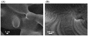
- the SEM image of the Fe 99.1 Cr 0.9 soft magnetic material (Example 1) (the numerical values in the figure are the Cr content (atomic%) in the cross portion, and is the average value in the region of radius 100 nm to 150 nm. ).
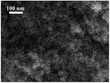
- the SEM image of the Fe 99.0 Nb 1.0 soft magnetic material (Example 25) (the numerical values in the figure are the Nb content (atomic%) in the cross portion, and is the average value in the region of radius 100 nm to 150 nm. ).
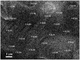
- the SEM image of the Fe 99.9 Zn 0.1 soft magnetic material (Example 46) (the numerical values in the figure are the Zn content (atomic%) in the cross portion, and is the average value in the region of radius 100 nm to 150 nm. ).
- magnetic material refers to a magnetic material referred to as “soft magnetic” (i.e., “soft magnetic material”) and a magnetic material referred to as “semi-hard magnetic material” (i.e. “semi-hard magnetic material ").
- soft magnetic material refers to a magnetic material having a coercive force of 800 A / m ( ⁇ 10 Oe) or less
- spinmi-hard magnetic material refers to a coercive force exceeding 800 A / m to 40 kA / m ( ⁇ 500 Oe) or less magnetic material.
- a semi-hard magnetic material is required to have an appropriate coercivity depending on the application and to have high saturation magnetization and residual magnetic flux density. Among them, soft magnetic or semi-hard magnetic materials for high frequency generate large eddy currents, so that the materials have high electrical resistivity, reduce the diameter of powder particles, or thin plate or strip It will be important to
- magnétique coupling refers to a state in which adjacent spins in a magnetic substance are strongly coupled by exchange interaction, and in the present invention, in particular, two adjacent crystal grains (and / or amorphous grains). ) In which the spins in the crystal are strongly connected by exchange interaction across the crystal boundary.
- grain such as crystal grains are lumps that can be recognized as being composed of one or more "phases" and separated from the three-dimensional space with a boundary.
- the exchange interaction is an interaction that extends only to the distance based on the short distance order of the material, when the nonmagnetic phase exists at the crystal boundary, the exchange interaction does not work on the spin in the regions on both sides, and the crystal grains on both sides There is no ferromagnetic coupling between (and / or amorphous particles).
- the term "crystal grain” sometimes includes amorphous grains. Further, the characteristics of the magnetic curve of the material in which ferromagnetic coupling is made between different kinds of adjacent crystal grains having different magnetic properties will be described later.
- disproportionation means that two or more kinds of phases different in composition or crystal structure are produced by chemical reaction from a phase having a homogeneous composition, and in the present invention, the homogeneous It is brought about as a result of the reduction reaction involving a reducing substance such as hydrogen involved in the composition phase.
- the chemical reaction that leads to this "disproportionation” is referred to herein as the “disproportionation reaction”, but water is often by-produced during this "disproportionation” reaction.
- M-ferrite is a material in which the Fe component of magnetite Fe 3 O 4 is substituted with M component, and the M component is Zr, Hf, V, Nb, Ta, Cr, Mo, W is one or more of W, Cu, Zn, and Si, and the M component may be simply described as M.
- the M component oxide is a substance or material in which an M component and oxygen O are bonded, and among them, one which is nonmagnetic (in the present application, also includes a case of very low magnetism).
- TM component or “TM” they refer to any one or more of Ti and Mn.
- the meaning of "contains Fe and M components” means that the magnetic material of the present invention necessarily contains Fe and M components as its components, and optionally the M component is other than the above.
- a certain amount may be replaced by an atom (specifically, one or more of Ti and Mn, which will be referred to as a TM component in the present application), and oxygen (O component) may be contained.
- O component or iron oxyhydroxide is present as a secondary phase
- H may be contained mainly as an OH group, and other unavoidable impurities, alkali metals such as K derived from the raw material, Cl, etc. It may be An alkali metal such as K is a suitable component in that it may exert an accelerating effect on the reduction reaction.
- magnetic powder generally refers to powder having magnetism, in the present application, the powder of the magnetic material of the present invention is referred to as “magnetic material powder”. Therefore, “magnetic material powder” is included in “magnetic powder”.
- the present invention relates to a magnetic material including a phase (first phase) in which the M component is contained in the ⁇ -Fe phase, and an M component-enriched phase (second phase) having an M component content higher than that phase. So, the best form is “powder” in which both phases are mixed and combined at nano level.
- These magnetic material powders are compacted as they are or sintered and used in various devices.
- it can be molded by blending an organic compound such as resin, an inorganic compound such as glass or ceramic, or a composite material thereof.
- composition, crystal structure and form, crystal grain size and powder grain size of the first phase containing Fe and M components and the second phase enriched with M components, and a method for producing them, among them A method of producing a nano-composite oxide powder to be a precursor of the magnetic material of the present invention, a method of reducing the powder, a method of solidifying the reduced powder, and a method of annealing in each step of these manufacturing methods Will be explained.
- the first phase is a crystal having a bcc structure cubic crystal (space group Im3m) containing Fe and M components as a crystal structure.
- the M component content of this phase is preferably 0.001 at% or more and 33 at% or less, assuming that the total (total content) of Fe and M components contained in the phase is 100 atomic%. That is, the composition of the first phase is expressed as Fe 100-x M x (x is 0.001 ⁇ x ⁇ 33 in atomic percentage) using the composition formula.
- the M component content or the Fe content is the sum of Fe and M components contained in the phase (in the present application, it may be referred to as the total content as described above, or the total amount). It refers to the value of the atomic ratio of M component or Fe to In the present invention, this may be expressed in atomic percent, where the total (total content) of Fe and M components contained in the phase is 100 atomic percent.
- the M component content As a property common to each of the M components, it is preferable to set the M component content to 33 atomic% or less in order to suppress the decrease in the magnetization.
- the M component content when the M component content is 20 atomic% or less, it is more preferable because magnetization exceeding 1 T can be realized depending on the manufacturing method and conditions. If the content is further 10 atomic% or less, it is particularly preferable because the saturation magnetization can be made to a magnetic material exceeding 1.6 T. Further, it is preferable to use 0.001 atomic% or more, unlike the case of Fe alone, in that adjustment of magnetic characteristics in the soft magnetic region by the effect of M component addition, for example, addition of magnetic saturation suppressing ability is possible .
- the range of the content of particularly preferable M component is 0.01 atomic percent or more and 10 atomic percent or less, and in this region, depending on the manufacturing conditions, a semi-hard magnetic material can be prepared from soft magnetic, particularly high frequency It can be a soft magnetic or semi-hard magnetic material having absorption ability, and it becomes possible to manufacture a magnetic material having more preferable electromagnetic properties. If it is desired to make the magnetization of a soft magnetic material with a higher degree of magnetization at the expense of a little coercive force, it is preferable to set the M component content of the first phase to 5 atomic% or less.
- the first phase of the Fe-M composition having this bcc structure is also referred to as the ⁇ - (Fe, M) phase in the present application, since the crystal symmetry is the same as that of the ⁇ phase which is the room temperature phase of Fe.
- the M component content of the first phase of the present invention is 100 atomic percent
- 0.001 atomic percent or more and less than 50 atomic percent of the M component is a TM component (that is, any one or more of Ti and Mn)
- the M component contained in the first phase has a composition substituted by the TM component
- the combination of M in the composition and the TM component is the above-mentioned "M component”.
- the M component content is 100 atomic%.
- adding a large number of element species to the soft magnetic material of the present invention has the effect of increasing the entropy of the magnetic material and reducing the coercivity.
- Cr is contained in the M component
- a soft magnetic material or a semi-hard magnetic material having a large saturation magnetization is obtained.
- V, Cr and Mo as the M component is effective in that the nanocrystallites of the present invention can be easily produced without largely depending on the temperature lowering rate in the reduction treatment and the annealing treatment.
- the use of Zr, Hf, Cr, V, Zn, Ta, Cu, or Si as the M component is preferable as a component of the soft magnetic material of the present invention because the anisotropic magnetic field is reduced.
- the M component When one or more of Zr, Hf, V, Nb, Ta, Mo, and W are used as the M component, the addition of 1 atomic percent or less by atomic percentage when the M component content of the first phase is 100 atomic percent However, it is possible to suppress "inappropriate grain growth" in the reduction step. It is preferable to use Cu, Zn or Si as the M component because this improves the oxidation resistance and the formability. Furthermore, when the TM component is co-added, not only the above effects but also a unique synergistic effect in which low coercivity and high magnetization are compatible may be exhibited.
- the M component is 0.01 atomic% or more and 50 atomic% depending on the TM component. Assuming that substitution is made in the range of less than 100 , the composition formula is Fe 100-x (M 100 -y TM y ) x / 100 (x, y is an atomic percentage 0.001 ⁇ x ⁇ 33, 0.001 ⁇ y ⁇ 50, M represents at least one of Zr, Hf, V, Nb, Ta, Cr, Mo, W, Cu, Zn, and Si, and TM represents at least one of Ti and Mn).
- any of the TM components addition of 0.001 atomic% or more by atomic percentage when the TM component content of the first phase is 100 atomic% is preferable from the viewpoint of the effect by the above-mentioned co-addition, 50 atomic% The addition of less than this is preferable from the viewpoint of preventing inhibition of various effects by the M component in the magnetic material of the present invention.
- 0.001 atomic% or more and less than 50 atomic% of Fe may be replaced with “coherent” with Co and / or Ni.
- the term "homogeneous" means that the content of the component in the phase is generally within a fluctuation of ⁇ 4.76% (ie, for example, in a material having a Co content of 10 atomic%, the Co content of each phase is The amount is in the range of 9.524 to 10.476 at%).
- Co coexistence not only increases the saturation magnetization but also has the effect of decreasing the coercivity.
- Ni is preferable because the addition of 5 atomic% or less improves the saturation magnetization and the substitution of 0.001 atomic% or more and less than 50 atomic% reduces the coercive force.
- mis-add means that the nano-fine structure of the magnetic material of the present invention is broken and the grains grow with a uniform crystal structure.
- “proper grain growth” in the present invention refers to disproportionation reaction after the powder particle size grows large while maintaining the nano-fine structure that is the feature of the present invention, or the powder particle size grows large. Either a nano-fine structure appears in the crystal due to phase separation or the like, or both.
- grain growth in the present invention refers to grain growth which is not “inappropriate grain growth” described above, and refers to grain growth which can be said to be generally appropriate.
- grain growth of either “proper grain growth” or “inappropriate grain growth” occurs, the surface area of the magnetic material per unit mass or per unit volume decreases, so that the oxidation resistance is generally low. Tend to improve.
- M component or “M component” or “M component” is described in a formula such as “ ⁇ - (Fe, M)” phase or in a context for discussing magnetic material composition.
- the term “sum of Fe and M components” means the sum of Fe and M components if the component other than Fe is the M component alone, and In a composition in which 0.001 to less than 50 atomic percent is replaced by a TM component, the total content of Fe, M component, and TM component is meant.
- the content thereof is 5 atomic% or less, preferably 2 atomic% or less, more preferably 0.1 atomic% or less, particularly preferably the total (that is, the sum of Fe and M components contained in the first phase). It is 0.001 atomic% or less.
- the target range may be exceeded.
- a component such as an alkali metal such as K which acts as a reducing aid when contained to some extent, and 0.001 atomic% of the whole (that is, the sum of Fe and M components contained in the first phase)
- K an alkali metal
- 0.001 atomic% of the whole that is, the sum of Fe and M components contained in the first phase
- the ⁇ -Fe phase not containing the M component is not included in the first phase or the second phase.
- the ⁇ -Fe phase not containing the M component when the content of elements other than the M component is also extremely small, saturation magnetization similar to electromagnetic soft iron is expected, but the ⁇ -Fe phase is a powder in the nano region Also, it has a poor influence on the electrical resistivity, is poor in oxidation resistance, and is poor in machinability.
- the ⁇ -Fe phase not containing the M component may be present as a separate phase as long as the object of the present invention is not impaired.
- the volume fraction of the ⁇ -Fe phase is preferably less than 50% by volume with respect to the entire magnetic material of the present invention.
- the volume fraction referred to here is the ratio of the volume occupied by the target component to the total volume of the magnetic material.
- the second phase is a phase in which the content of the M component with respect to the total of Fe and M components contained in the phase is higher than the content of the M component with respect to the total of Fe and M components contained in the first phase. It is.
- the atomic percentage of the M component to the total of Fe and M components contained in the phase is from the atomic percentage of the M component to the total of Fe and M components contained in the first phase. Is also a big phase.
- a rhombohedral M-hematite phase (typical composition is (Fe 1-u M u ) 2 O 3 phase, u depends on the kind of M component, for example, when M component is Cr, 0 ⁇ u ⁇ 1 ), Tetragonal system such as Cr 2 O 3 phase, tetragonal ⁇ -cristobalite phase (SiO 2 ), ⁇ -FeV phase, Cr 5 Si 3 phase, NbO 2 phase, etc.
- composition ratio is indicated by two figures of significant figures), etc., or a mixture thereof Can be mentioned.
- the amorphous phase, eutectic point composition phase and eutectoid point composition phase differ depending on the M component content and reduction conditions, but when an amorphous phase or the like is present It is separated from the first phase and exists as islands without taking a fine structure such as floating in the ocean of an island with microcrystals like the existing nanocrystal-amorphous phase separation type material mentioned above. There are many things to do.
- the content of the amorphous phase or the like is between 0.001 and 10% by volume, and it is preferable from the viewpoint of suppressing the decrease in the magnetization that it is not more than this, and in order to make the magnetic material of high magnetization further preferable.
- the amorphous phase or the like may be intentionally included in order to control the disproportionation reaction itself, but in this case, it is preferable to be more than 0.001% by volume from the viewpoint of exerting the reaction control effect.
- the volume fraction referred to here is the ratio of the volume occupied by the target component to the volume of the entire magnetic material.
- the second phase described above has lower saturation magnetization than the first phase, but the coexistence of these phases significantly increases the electrical resistivity. Furthermore, in the present invention, the coercivity is improved when the semi-hard magnetic material is formed. On the contrary, in the present invention, when the soft magnetic material is formed, a small coercive force can be realized by ferromagnetically coupling with the phase depending on the crystal structure, composition, microstructure, interface structure, etc. of the phase. Furthermore, also in the second phase, as in the first phase, less than 50 atomic% of the M component content (however, the content of the M component of the second phase is 100 atomic%) can be replaced with the TM component .
- the “M component” of the second phase also has a composition in which the M component contained in the second phase is substituted by the TM component as in the “M component” of the first phase described above.
- phase which contains neither Fe nor M component and is mixed only with the compound of the TM component is not included in the first phase or the second phase. However, it may contribute to the improvement of the electrical resistivity, the oxidation resistance, the sinterability, and the electromagnetic characteristics of the semi-hard magnetic material of the present invention.
- the phase which does not contain the M component such as the compound phase of the TM component and the Fe compound phase described above, and the phase in which the content of the TM component is the content of the M component element or more is referred to as "subphase" in this application.
- Phases other than the first phase and the second phase Phases other than the first phase and the second phase, w-phase which does not contain M component, M-phase (Fe 3 O 4 ), maghemite phase ( ⁇ -Fe 2 O 3 ), hematite phase ( ⁇ -Fe 2 O 3) ), Secondary phases such as ⁇ -Fe phase, ⁇ -Fe phase, and with or without M component, iron oxyhydroxide such as goethite, achagenite, lepidocrocite, ferrooxyhytite, ferrihydrite, green last etc.
- M-phase Fe 3 O 4
- maghemite phase ⁇ -Fe 2 O 3
- hematite phase ⁇ -Fe 2 O 3
- Secondary phases such as ⁇ -Fe phase, ⁇ -Fe phase, and with or without M component, iron oxyhydroxide such as goethite, achagenite, lepidocrocite, ferrooxyhytite, ferrihydrite, green
- phase hydroxide such as potassium hydroxide and sodium hydroxide, chloride such as potassium chloride and sodium chloride, fluoride, carbide, nitride, hydride, sulfide, nitrate, carbonate, sulfate, silicate And phosphates, etc., but because these volumes have high saturation magnetization, the magnetic material of the present invention also exhibits stable magnetic characteristics and high magnetization over time. First Less than the volume that is required. From the viewpoint of suppressing the decrease in saturation magnetization, the preferable range of the content of these phases is 50% by volume or less with respect to the volume of the entire magnetic material.
- the content of the TM component of all the phases including the first phase, the second phase and the subphase should not exceed the content of the M component contained in the first phase and the second phase with respect to the whole phase.
- the TM component is contained in excess of the M component content, the effect on the electromagnetic characteristics unique to the M component, for example, the reduction of the magnetocrystalline anisotropy, the improvement of the electrical resistivity, and the oxidation resistance by passivation of the powder surface It is because the peculiar feature such as improvement is lost.
- the M component content of the first phase and / or the second phase means an amount including such a TM component.
- the second phase may have the same crystal structure as the first phase, but it is desirable that the compositions be sufficiently different from each other, for example, the second phase with respect to the sum of Fe and M components in the second phase.
- the M component content of is greater than the M component content of the first phase with respect to the total of Fe and M components in the first phase, and the difference is at least 1.5 times and / or the second phase It is preferable that the M component content of the second phase is 2 atomic% or more with respect to the total of Fe and M components contained therein.
- the M component content itself of the second phase does not exceed 100 at%.
- the M component content of the second phase does not exceed 10 5 times the M component content of the first phase.
- the M component content of the second phase is preferably 90 atomic% or less of the M component content of the first phase.
- the M component content of the second phase is “1.5 times or more” of the first phase, the M component content of each phase is determined by one or more significant figures, The M component content of the second phase is 1.5 or more times the M component content of the first phase.
- the present invention aims to reduce the coercive force by utilizing the above-mentioned random magnetic anisotropy model or the fluctuation of the magnetic anisotropy according to the model, and is a crystallographically independent first phase
- the second phase are magnetically coupled by exchange coupling at the nano level, or the M component content in the bcc phase including the first phase and the second phase changes spatially at the nano scale It is important that there is a certain thing (this may be called "concentration fluctuation" in the present invention).
- the M component content of the second phase is preferably 2 atomic% or more, more preferably 5 atomic% or more, based on the total of Fe and M components in the second phase.
- the magnetocrystalline anisotropy of the two phases is reduced to half or less compared to the case where the M component is not contained. If the M component content is 8 atomic% or more, it is further preferable because the magnetocrystalline anisotropy becomes extremely small.
- phase (first phase) in which the M component content is lower than the M component content of the entire magnetic material of the present invention the phase (second phase) in which the M component content is higher than the magnetic material of the present invention is also the same In the magnetic material. Therefore, if they are ferromagnetically coupled to achieve isotropy, the magnetic material of the present invention, specifically a soft magnetic material, is obtained, and the coercive force is appropriately determined by interposing at the interface of the first phase.
- the magnetic material of the present invention specifically a semi-hard magnetic material, can be obtained if it has the function of increasing the electrical resistance as a range.
- the magnetic material of the present invention whose coercivity is lowered by such a mechanism often has a content of 10 at% or less with respect to the sum of the M component and Fe in the magnetic material.
- the above is a composition with high homogeneity, which completely removes heterophases and is not found in many existing soft magnetic materials such as electromagnetic steel sheets designed to prevent domain wall movement from being disturbed, such as Sendust. It is a feature of the material, and it can be said that magnetization reversal is a feature common to magnetic materials caused by the rotation of magnetization.
- a state in which only the first phase or only the second phase is magnetically coupled at the nano level by exchange coupling may be included, and even in this case, the crystal axis orientations of adjacent nanocrystals are not aligned. It is important that there is a nanoscale spatial distribution of M component content in the bcc phase that is isotropic or contains the first and second phase.
- a magnetic material composed of microcrystallines of only the first phase or a magnetic material composed of microcrystallines of only the second phase can not be achieved, and even when such a structure is included, In the present invention, the first phase and the second phase are always present in the magnetic material.
- nanocrystals itself is a powder of ferrite containing an M component, which is used to produce the magnetic material of the present invention, wherein the powder has a nanoscale size (herein The reason is that it is greatly involved in the disproportionation reaction in each process of the reduction process starting from the reduction of the ferrite nanopowder or the “M component—ferrite nanopowder”.
- a ferrite powder of nanoscale size is also referred to as "ferrite nanopowder”
- the nanoscale refers to a scale of 1 nm or more and less than 1 ⁇ m unless otherwise specified.
- the first phase is the ⁇ - (Fe, M component) phase, which mainly ensures high saturation magnetization.
- the second phase is a phase in which the content of the M component to the total of Fe and M components contained in the phase is larger than the content of the M component to the total of Fe and M components contained in the first phase.
- the second phase may be an ⁇ - (Fe, M component) phase which is higher than the M component content of the entire magnetic material, or may be another crystalline phase or an amorphous phase, or a mixed phase thereof.
- the soft magnetic material of the present invention has the effect of keeping the coercivity low, and even including the semi-hard magnetic material, has the effect of imparting oxidation resistance and improving the electrical resistivity. Therefore, since the second phase is an aggregate of the phases having these effects, the magnetic properties of the present invention should be able to indicate the presence of any of the previously exemplified phases, in which the content of the M component is higher than that of the first phase. It turns out that it is a material. If such a second phase does not exist and is constituted only by the first phase, any one of the magnetic properties such as the coercive force, the oxidation resistance and the electrical conductivity is inferior, and in the processability, It becomes a magnetic material which is scarce and complicates the molding process.
- the composition of the first phase and the M component may change continuously.
- the M component composition of the first phase and the second phase changes continuously.
- the M component content of the second phase (that is, the M component content in the second phase to the total of the Fe and M components contained in the second phase) is the M component content (the first phase) That is, the content of M component in the first phase is 1.5 times or more of the total of Fe and M components contained in the first phase, or the content of M component in the second phase is 2 atomic% or more It is preferable that the M component content of the first phase be greater than that of the first phase, or that the M component content of the second phase be 1.5 or more times and 2 atomic% or more of the M component content of the first phase.
- the content of M in the second phase is 1.5 times or more the content of M in the first phase, which makes it possible to adjust the electromagnetic characteristics such as the coercivity.
- the M component is mainly contained, twice or more is more preferable, and when it is twice or more also when Cr is mainly contained, a preferable range is to obtain a soft magnetic material having a small coercive force.
- composition ratio of Fe to M component is 1: 1 or less in combination of the first phase and the second phase, in other words, the content of M component is 100 atomic% with the content of Fe and M component being 100 atomic%. It is desirable that the content be 0.01 atomic percent or more and 50 atomic percent or less.
- the content of the M component in which the first phase and the second phase are combined be 50 atomic% or less in order to avoid a decrease in saturation magnetization, and that it is 0.01 atomic% or more is oxidation resistance There is no addition effect of M component to etc., and it is preferable in order to avoid that a coercive force becomes high to such an extent that it does not respond to the target application.
- the content of the M component combining the first phase and the second phase is preferably 0.05 atomic% or more and 33 atomic% or less, of which the particularly preferable range Is 0.1 atomic% or more and 25 atomic% or less.
- the volume ratio of the first phase to the second phase is arbitrary, the first phase, or the first phase and the first phase, relative to the volume of the entire magnetic material of the present invention including the first phase, the second phase and the subphase.
- the total volume of the ⁇ - (Fe, M component) phase in the second phase is preferably 5% by volume or more. Since the ⁇ - (Fe, M component) phase is responsible for the main magnetization of the magnetic material of the present invention, it is preferably 5% by volume or more in order to avoid a decrease in the magnetization. Furthermore, it is preferably 25% by volume or more, more preferably 50% by volume or more. In order to realize particularly high magnetization without significantly reducing the electrical resistivity, it is desirable to set the total volume of the ⁇ - (Fe, M component) phase to 75% by volume or more.
- a ferromagnetic or antiferromagnetic (herein, weak magnetism is also included in this phase) phase, because the crystal magnetism of the first phase is the reason It is because it has the effect of reducing anisotropy.
- the M component content of the second phase with respect to the sum of the Fe and M components in the second phase is Fe in the first phase
- the M content is higher than the first phase relative to the sum of the M and M components, and preferably, the M content is 0.1 atomic% or more to the total of Fe and M components in the second phase.
- There is an ⁇ - (Fe, M component) phase which is atomic% or less, more preferably 2 atomic% to 15 atomic%, particularly preferably 5 atomic% to 10 atomic%.
- the first phase also contains an M component content of 5 at% or more and 10 at% or less based on the total of Fe and M components in the first phase, but the M component is contained to this extent As the amount is increased, saturation magnetization close to 2T can not be exhibited. Therefore, by combining the first phase having an M component content of less than 5 atomic% and the second phase having an M component content of 5 atomic% or more, a magnetic material having a large saturation magnetization and a small coercive force is realized. Is preferred.
- preferable second phase includes M-ferrite phase and wustite phase.
- the former is ferromagnetic and the latter is antiferromagnetic, but any one can promote ferromagnetic coupling if it is between the first phase.
- These oxide phases may be nano-sized and have a very fine structure, and particularly in the wustite phase, a few atomic layers are finely dispersed in the bcc phase or layered between the bcc microcrystalline phases. It may also exist. When such an oxide layer is present, the crystal orientation of the bcc phase may be aligned in a region of several hundred nm to several tens of ⁇ m, but even in such a microstructure, the crystal grain size of the present invention, etc.
- the magnetic material of the present invention is included in the range of In particular, when the magnetic material having the above structure is a soft magnetic material, the coercivity is lowered by a mechanism slightly different from random anisotropy. It is assumed that the mechanism is as follows. Due to disproportionation, between the M component content of the first phase to the total of Fe and M components in the first phase, and the M component content of the second phase to the total of Fe and M components in the second phase If there is a difference in the density, and there is a spatially fluctuating concentration of nanoscale fine M component content, a spatial fluctuation of the magnetic anisotropy occurs, and when an external magnetic field is applied (as if It is included in the mechanism that the magnetization is switching as if the resonance phenomenon occurred.
- the above-mentioned fluctuation in concentration has the same effect of reducing the coercive force not only when the second phase is an oxide phase but also when it is an ⁇ - (Fe, M component) phase.
- ferrite phase promotes ferromagnetic coupling
- WO 2009/057742 hereinafter referred to as "patent document 1”
- N. Imaoka, Y. Koyama, etc. T. Nakao, S. Nakaoka, T. Yamaguchi, E. Kakimoto, M. Tada, T. Nakagawa, and M. Abe, J. Appl. Phys., Vol. 103, No. 7 (2008) 07E129 (hereinafter referred to as
- a ferrite phase exists between Sm 2 Fe 17 N 3 phases of a hard magnetic material, and these phases are ferromagnetically coupled to constitute an exchange spring magnet. is there.
- the present invention relates to a soft magnetic material and a semi-hard magnetic material, and the function to be exhibited is completely different from the above hard magnetic exchange spring magnet.
- the second phase which is the M-ferrite phase or the wustite phase
- mediates the exchange interaction between the first phase if such a second phase exists to surround the first phase,
- the electrical resistance is also high and the coercivity is reduced. Therefore, it is one of the highly preferable second phases particularly in the soft magnetic material of the present invention.
- the presence of a nonmagnetic M-component oxide phase in the second phase is preferable because the electrical resistance is particularly improved. Even if they exist between the first phase, they produce ferromagnetic coupling like M-ferrite phase and do not have a direct effect on the magnetic properties, but to cover the surface of these ferromagnetically coupled powders
- the presence of the M component oxide not only improves the electrical resistance and the oxidation resistance, but in some cases, may have the effect of reducing the coercive force.
- the volume fraction of the mixed oxide phase is Preferably, the total volume of the magnetic material is 95% by volume or less, more preferably 75% by volume or less, and still more preferably 50% by volume or less.
- the M-ferrite phase has lower magnetization than the ⁇ - (Fe, M) phase although it is ferromagnetic, and the wustite phase is also weakly magnetic even if it is antiferromagnetic, and although magnetization is present to some extent, the M-ferrite The magnetization is lower than that of the phase.
- the M component oxide phase is nonmagnetic.
- the magnetization of the magnetic material of the present invention becomes extremely low if it exceeds 95% by volume of the entire magnetic material in any combination of the above oxide phases, and to avoid that, 95% by volume of the entire magnetic material is avoided It is preferable to set it as the following.
- the wustite phase or M component oxide phase is the main component, the content of these three oxide phases is lower than 75% by volume, so that the magnetization is low.
- the volume% or less and when the M component oxide phase is the main component, the characteristics of the magnetic material of the present invention having high magnetization are lost when it exceeds 50 volume%. It is preferable to set it as 50 volume% or less of the whole magnetic material.
- the magnetic material is particularly high in magnetization while maintaining the electrical resistivity to a certain extent, it is preferable to set the oxide phase to 25 volume% or less.
- the preferred volume fraction is 0.001% by volume or more, particularly not very much.
- 0.01% by volume or more is more preferable, and particularly preferably 0.1% by volume or more in order to effectively improve the electrical resistivity.
- the range of the above-mentioned preferable volume fraction and the like are the same.
- the ⁇ - (Fe, M) phase, the M-ferrite phase, the wustite phase, and the M component oxide phase having an M component content higher than the first phase are exemplified.
- the three phases other than the M component oxide phase are ferromagnetic or antiferromagnetic.
- the magnetic curve is additive, so the magnetic curves of these mixed materials are simply the sum of the respective magnetic curves, and the entire magnetic material
- a smooth step on the magnetic curve of For example, when the magnetization is measured in a wide magnetic field range of 0 to 7.2 MA / m from the external magnetic field, the 1/4 major loop (from 7.2 MA / m to the zero magnetic field) of the magnetic curve of the entire magnetic material If you look at the shape of the 1 ⁇ 4 major loop) of the magnetic curve of (1), it is certain that the smooth step due to the above circumstances or the inflection point based on it is certain on the 1 ⁇ 4 major loop I can guess.
- the local compositional analysis of the metal element of the magnetic material of the present invention is mainly performed by EDX (energy dispersive X-ray spectroscopy), and the compositional analysis of the entire magnetic material is XRF (fluorescent X-ray) Elemental analysis was performed.
- EDX energy dispersive X-ray spectroscopy
- XRF fluorescent X-ray Elemental analysis
- the M component content of the first phase and the second phase is measured by an EDX apparatus attached to SEM (scanning electron microscope), FE-SEM, or TEM (transmission electron microscope) (in the present invention, this is used)
- SEM scanning electron microscope
- FE-SEM scanning electron microscope
- TEM transmission electron microscope
- the crystal structure of the first phase and the second phase is a fine structure of 300 nm or less, accurate composition analysis can not be performed by SEM or FE-SEM, but M of the magnetic material of the present invention If it is only for detecting the difference between the components and the Fe component, it can be used supplementarily. For example, to find a second phase less than 300 nm with an M component content of 5 atomic% or more, one point in the magnetic material is observed, and its quantitative value is 5 atomic% or more as an M component content. If it is confirmed that there is a tissue having an M component content of 5 atomic% or more, or a part of the tissue, within a range of 300 nm in diameter centered on that one point.
- the magnetic material in order to find the first phase in which the M component content is 2 atomic% or less, one observation in the magnetic material is performed, and the quantitative value is 2 atomic% or less as the M component content. If it is confirmed that there is a structure with a M component content of 2 atomic% or less or a part of the structure within the range of 300 nm in diameter centering on that one point.
- composition analysis is performed using an EDX apparatus attached to a TEM, for example, the electron beam can be narrowed to 0.2 nm, and very fine composition analysis can be performed.
- it is necessary to handle a large amount of data for example, 60,000 points, in order to thoroughly examine a certain area and obtain an overview of the material of the present invention. That is, in view of the composition of the magnetic material of the present invention, it is necessary to specify structural features such as the composition of the first phase and the second phase, the crystal grain size, and the like by appropriately selecting the composition distribution measuring method described above.
- the composition of the ⁇ - (Fe, M) phase can also be determined by confirming the position of the diffraction peak by means of XRD (X-ray diffractometer).
- the diffraction peaks of the ⁇ - (Fe, M) phase tend to shift to lower angles generally as the M content increases, and among them, the behavior of the (110) and (200) peaks is observed.
- ⁇ -Fe diffraction positions by referring to the method of the present invention, Fe-ferrite nanopowders containing no M component or TM component are separately prepared and compared as comparative examples
- the M component content of the Fe, M phase can also be known with one significant digit.
- the present invention is characterized by disproportionation of the M composition and the existence of various crystal phases, and it is useful to verify whether or not their crystal axes are randomly oriented. Furthermore, in order to distinguish the ⁇ - (Fe, M) phase from other oxide phases, it is convenient and effective to analyze an oxygen characteristic X-ray surface distribution map using, for example, SEM-EDX.
- each composition in the whole magnetic material in the present invention (that is, each composition in the case where the total content of components constituting the whole magnetic material is 100 atomic%) has an Fe component of 20 atomic% or more and 99.999 atomic% or less, It is preferable that the M component be in the range of 0.001 atomic% to 50 atomic%, and the O (oxygen) content be in the range of 0 atomic% to 55 atomic%, which simultaneously satisfy these. Furthermore, an alkali metal such as K may be contained at 0.0001 atomic% or more and 5 atomic% or less. It is desirable that the subphases including K and the like do not exceed 50% by volume of the whole.
- the range of 55 atomic% or less not only has a low saturation magnetization but also a first phase by reduction of the M component-ferrite nanopowder or It is preferable because disproportionation reaction to the second phase does not occur and it is possible to avoid difficulty in developing a low coercivity into a soft magnetic material.
- the magnetic material of the present invention does not necessarily contain oxygen, but in order to obtain a magnetic material having extremely high oxidation resistance and electrical resistivity, it is preferable to contain as little as possible.
- the surface of the metal powder reduced in the gradual oxidation process to be described later may be passivated, or a portion of the crystal grain boundaries of the solid magnetic material, mainly by the M component oxide, by one operation.
- the composition range in the entire magnetic material of the present invention is 20 atomic% or more and 99.998 atomic% or less of the Fe component, and 0.001 of the M component. It is desirable that the atomic percent or more and 50 atomic percent or less, and the O content be in the range of 0.001 atomic percent or more and 55 atomic percent or less.
- More preferable composition of the magnetic material of the present invention is that the Fe component is 50 atomic% or more and 99.98 atomic% or less, the M component is 0.01 atomic% or more and 49.99 atomic% or less, O is 0.01 atomic% or more and 49
- the magnetic material of the present invention which is not more than .99 atomic%, in this range, has a good balance of saturation magnetization and oxidation resistance.
- the magnetic material of the invention is preferable in that it has excellent electromagnetic properties and excellent oxidation resistance.
- the Fe component is 79.95 atomic% or more and 99.9 atomic% or less, and the M component is 0 It is preferable that the composition range is 0.05 atomic percent or more and 20 atomic percent or less, and O is 0.05 atomic percent or more and 20 atomic percent or less.
- the semi-hard magnetic material tends to contain more oxygen than the soft magnetic material in the present invention, although it can not be generally said.
- One of the present invention is a magnetic material having magnetic properties and electrical properties suitable for soft magnetic applications having a coercive force of 800 A / m or less and oxidation resistance, which will be described below.
- magnetic properties refers to the magnetization J (T), saturation magnetization J s (T), magnetic flux density (B), residual magnetic flux density B r (T), and exchange stiffness constant A (J / m) of a material.
- Magnetocrystalline anisotropy magnetic field H a (A / m), magnetocrystalline anisotropy energy E a (J / m 3 ), magnetocrystalline anisotropy constant K 1 (J / m 3 ), coercive force H cB ( A / m), intrinsic coercive force H cJ (A / m), permeability ⁇ ⁇ 0 , relative permeability ⁇ , complex permeability ⁇ r ⁇ 0 , complex relative permeability ⁇ r , its real term ⁇ ', imaginary term ⁇ And at least one of the absolute values
- the unit of “magnetic field” is a combination of A / m of SI unit system and Oe of cgs Gaussian unit system.
- oxidation resistance refers to various oxidizing atmospheres such as room temperature air. It is a time-dependent change of the above-mentioned magnetic property.
- electromagnetic properties The above magnetic properties and electrical properties are collectively referred to as "electromagnetic properties”.
- magnetization, saturation magnetization, magnetic flux density, residual magnetic flux density, and electrical resistivity are preferably higher, and for saturation magnetization, a height of 0.3 T or 30 emu / g or more is desirable, particularly soft magnetic In terms of materials, a height of 100 emu / g or more is desirable, and a height of 1.5 ⁇ m or more is desirable for the electrical resistivity.
- Other magnetic properties of the present invention such as magnetocrystalline anisotropy constant, coercivity, permeability, relative permeability, etc., are suitable depending on the application, including whether it is a semihard magnetic material or a soft magnetic material. Control.
- the permeability and the relative permeability do not necessarily have to be high depending on the application, and if the coercivity is sufficiently low and the core loss is suppressed low, for example, the relative permeability is as large as around 10 ⁇ 1 to 10 5
- the limit thickness at which the eddy current loss occurs can be increased by about 3.2 times each time the magnetic permeability is lowered by one digit.
- One of the features of the present invention is to provide a magnetization reversal mechanism mainly by direct rotation of magnetization instead of magnetization reversal due to domain wall movement, so that the coercive force is low and the eddy current loss due to domain wall movement is also small, and iron loss is suppressed low.
- a major feature of the present invention is that by using the M component of the present invention, the relative permeability can be freely controlled, for example, compared to the case where there is no M component or only the TM component.
- the magnetic saturation suppressing ability (the function or the characteristic of the magnetic material which does not cause magnetic saturation) can be given according to the above.
- Zn, Si, Cu and Ta are mentioned as M component which raises relative magnetic permeability
- Zr, Hf, V, Nb, Cr, Mo and W are mentioned as M component which lowers relative magnetic permeability.
- the reason why the permeability can be adjusted is that the magnetic material has a large electrical resistivity just by sintering as it is, so that the iron loss due to the eddy current is small, and hence the coercivity is slightly sacrificed. This is because the total iron loss can still be kept small even if the hysteresis loss is slightly increased by designing the material to suppress the magnetic permeability.
- an electric resistivity of 1.5 ⁇ m or more can be exhibited, and in a semi-hard magnetic material, an even higher electric resistivity can be exhibited.
- the saturation magnetization tends to decrease as the electrical resistivity increases. Therefore, it is necessary to determine the composition and reduction degree of the raw materials There is. In particular, less than 1000 ⁇ m is preferable to obtain the feature that the magnetization of the magnetic material of the present invention is high. Therefore, the preferred range of the electrical resistivity is 1.5 ⁇ m to 1000 ⁇ m.
- ⁇ Crystalline boundary> Whether the magnetic material of the present invention becomes soft magnetic or semi-hard magnetic depends on the magnitude of the coercivity as described above, but it is particularly closely related to its fine structure.
- the ⁇ - (Fe, M) phase may be observed in the continuous phase at first glance, but as shown in (A) and (B) of FIG. (In the present invention, heterophase interface, polycrystal grain, etc. (in the present invention, twin phase, interphase interface, polycrystal grain, etc.)
- crystals are divided not only by the boundary but also by these various crystal habits, crystal phases, intergrowth structures, dislocations, etc., their interfaces are collectively referred to as “crystal boundaries” etc. It often contains crystal boundaries as curve groups, unlike the usual linear grain boundaries, and in such a structure, there is a large difference in M component content depending on the location. Seen.
- the magnetic material of the present invention having the fine structure as described above is often a soft magnetic material.
- the first phase and the second phase start from M-ferrite nanopowder when the second phase is an ⁇ - (Fe, M) phase.
- the ⁇ - (Fe, M) phase, the first phase and the second phase have various fine structures such as crystals of gemstones such as quartz, minerals such as pyrite and meteorites, and crystals of rocks. It is held in a reduced scale, and internally contains various phases and nanocrystals with various M component contents.
- the texture that looks like grain boundaries and intergrowths also has a difference in M component content depending on the observation site, and may be a heterophase interface.
- ⁇ Random magnetic anisotropy model and mechanism of lowering coercivity unique to the present invention In the soft magnetic material of the present invention described by the random anisotropy model, it is important to satisfy the following three conditions. (1) The grain size of the ⁇ - (Fe, M) phase is small, (2) ferromagnetic coupling by exchange interaction, (3) It has random orientation. With regard to (3), it is not necessarily essential especially in a region where the content of M component of the bcc phase is 10 atomic% or less, and in this case, the lowering of the coercive force occurs on the principle different from the random anisotropy model .
- the fluctuation of the magnetic anisotropy based on the fluctuation of the concentration of the M component content on the nanoscale becomes As a result, the magnetization reversal is promoted and the coercivity is reduced.
- the magnetization reversal mechanism by this mechanism is unique to the present invention, and as far as the present inventors can know, it has been found for the first time by the present inventors.
- the grain growth occurs during reduction, when the particles are not fused so that the ferromagnetic phase continues, or when phase separation occurs such that the particles are separated.
- the first phase and the second phase are bonded directly or continuously through the metal phase or the inorganic phase. And it is desirable to make it as a mass as a whole.
- the above solidification is necessary.
- ⁇ Average grain size of first phase, second phase, entire magnetic material The average grain size of the first phase or the second phase of the soft magnetic material of the present invention, or the average grain size of the entire magnetic material is preferably 1 nm or more and less than 10 ⁇ m. When the average grain size of the first phase and the second phase is less than 10 ⁇ m, the average grain size of the entire magnetic material is also less than 10 ⁇ m.
- either the first phase or the second phase is in the nano region in order to realize the reduction of the coercive force by the above random magnetic anisotropy model or the mechanism unique to the present invention.
- both the first phase and the second phase are ferromagnetic phases, both preferably have an average crystal grain size of less than 10 ⁇ m, and less than 1 ⁇ m realizes reduction in coercive force based on a random magnetic anisotropy model.
- the thickness is 500 nm or less, and more preferably 200 nm or less because it has a remarkable reduction effect of the coercive force by the mechanism unique to the present invention although it depends on the content of the M component.
- the magnetic anisotropy energy of the first phase is often larger than that of the second phase, so in particular, if the first phase is less than 10 ⁇ m, preferably 500 nm or less, more preferably 200 nm or less
- the coercivity is extremely small, and it becomes a soft magnetic material suitable for various transformers, motors and the like.
- the thickness is less than 1 nm, the film becomes superparamagnetic at room temperature and the magnetization and the magnetic permeability may be extremely reduced. Therefore, the thickness is preferably 1 nm or more. As mentioned above, if crystal grains of less than 1 nm or an amorphous phase is present, it is required to sufficiently connect these to crystal grains of 1 nm or more by exchange interaction.
- the second phase When the second phase is not a ferromagnetic phase, the second phase does not contribute to the reduction of the coercive force by the above-described random anisotropic model or the mechanism unique to the present invention, but the presence of the second phase increases the electrical resistivity, which is a preferable component. It is.
- the first phase in order to express the coercivity contrary to the above, is maintained at an average grain size of nano level, and a suitable surface oxide layer is made the second phase, It is effective to make the second phase exist at the grain boundary of the first phase as an average crystal grain size of several nm, maintain high magnetization while expressing the coercivity of the semihard magnetic region, and impart oxidation resistance. It is.
- ⁇ Measurement of grain size> In the measurement of the crystal grain size of the present invention, an image obtained by a SEM method, a TEM method or a metallurgical microscope method is used. Within the observed range, not only the heterophase interface and the grain boundaries but also all the grain boundaries are observed, and the diameter of the crystal region in the portion surrounded by the grain boundaries is taken as the grain size. If it is difficult to see the crystal boundaries, it is better to etch the crystal boundaries using a wet method or dry etching method using a nital solution or the like.
- the average grain size is basically selected from a representative part and measured in a region including at least 100 crystal grains.
- the average crystal grain size is determined by photographing an observation area, defining an appropriate rectangular quadrilateral area on the photograph plane (enlarged projection plane to the photographing plane of the object), and applying the Jeffry method inside thereof.
- the crystal boundary width may be too small and may not be observed with respect to resolution, but in that case, the measured value of crystal grain size gives the upper limit of the actual crystal grain size. .
- the upper limit may have a crystal grain size measurement value of 10 ⁇ m.
- the magnetic material may cut the lower limit of the crystal grain size by 1 nm, for example, from phenomena such as not having a clear diffraction peak on XRD and superparamagnetism being confirmed on a magnetic curve. If indicated, the actual grain size must be determined again by TEM observation. Furthermore, in the present invention, it may be necessary to measure the crystal grain size regardless of the crystal boundary. That is, the crystal grain size of the magnetic material of the present invention having such a fine structure is the M component content, for example, when the crystal structure is finely modulated due to the fluctuation of the concentration of the M component content. The modulation width of is the grain size.
- the crystal grain size is often determined by TEM-EDX analysis or the like, but the size often corresponds approximately to the crystallite size described in the next section.
- a crystallite is a small single crystal at the microscopic level that constitutes a crystalline substance and is smaller than the individual crystals (so-called crystal grains) that constitute a polycrystal.
- the disproportionation reaction causes phase separation, and a compositional range occurs in the M component content of the bcc phase of the first phase and / or the second phase. Since the X-ray diffraction line peak position changes depending on the M component content, for example, even if the line width of the diffraction line at (200) of the bcc phase is determined and the crystallite size is determined from this, the error becomes large.
- the crystallite size obtained by this method may not be recognized as significant in the case of crystals of bcc phase structure containing an M component.
- the crystallite size obtained based on the diffraction line at (200) of the bcc phase is “apparent” as described above. It is called "crystallite size”.
- Ni and Co contained in substitution for the Fe component have an atomic radius close to that of Fe, and the degree of disproportionation is also small, and the change in crystallite size due to the composition distribution is hardly observed.
- the M component content of the bcc phase is 0.001 atomic percent or more and 1 atomic percent, the deviation of the diffraction line of (200) is very small, so within the range of 1 nm or more and 300 nm or less, the significant digit of 1 digit It is significant to measure crystallite size.
- At least the first phase is Fe 100-x M x (where x is an atomic percentage 0.001 ⁇ x ⁇ 1, M is Zr, Hf, V, Nb, Ta, Cr, Mo, W Crystals having the composition represented by the composition formula of any one or more of Cu, Zn, and Si), even when the apparent crystallite size of one significant digit is measured, substantially It can be regarded as "size". Therefore, the apparent crystallite size in such a case is simply referred to as "crystallite size" in the present application.
- the crystallite size is determined by using the (200) diffraction line width excluding the influence of the K ⁇ 2 diffraction line and the Scherrer equation, setting the dimensionless form factor to 0.9, and setting the crystallite size of the bcc phase I asked.
- the bcc phase may be at least the first phase having the phase (i.e., only the first phase has the bcc phase, or both the first phase and the second phase have the bcc phase).
- the preferred crystallite size range of the bcc phase is 1 nm or more and 300 nm or less. If it is less than 1 nm, it becomes superparamagnetic at room temperature and the magnetization and permeability may become extremely small.
- the crystallite size of the bcc phase is 200 nm or less, the coercivity enters the soft magnetic region and becomes extremely small, which is preferable because it becomes a soft magnetic material suitable for various transformers, motors and the like. Furthermore, since 100 nm or less is a region with a low M component content, not only high magnetization exceeding 2T can be obtained, but also low coercivity can be achieved simultaneously, which is a very preferable range.
- the apparent size of the crystallite size is a danger that is generally measured smaller than the “crystallite size” of a material in which the M component content of the bcc phase is 0.001 atomic% or more and 1 atomic% or less in general crystals.
- the magnetic material at least the first phase is Fe 100 -x M x (where x is an atomic percentage 0.001 ⁇ x ⁇ 33, M is Zr, Hf, V, Nb, Ta, Cr, In the crystal having a composition represented by the composition formula of any one or more of Mo, W, Cu, Zn, and Si), for example, the apparent crystallite size is in the range of 1 nm to 300 nm. If the thickness is limited to 1 nm or more and 200 nm or less, the above risk can be avoided. As a result, the relationship between crystallite size and magnetic property preferences described above is maintained. Therefore, in the magnetic material of the present invention, the “apparent crystallite size” limited to 1 nm or more and 200 nm or less is also simply referred to as “crystallite size”.
- the size of the powder of the soft magnetic material of the present invention is preferably 10 nm or more and 5 mm or less. If it is less than 10 nm, the coercivity does not become sufficiently small, and if it exceeds 5 mm, a large strain will be applied during sintering, and the coercivity will be large if there is no annealing treatment after solidification. More preferably, it is 100 nm or more and 1 mm or less, and particularly preferably 0.5 ⁇ m or more and 500 ⁇ m or less. If the average powder particle size falls within this range, it becomes a soft magnetic material with low coercivity.
- the particle size distribution is sufficiently wide within each average powder particle size range specified above, high filling can be easily achieved with a relatively small pressure, and the magnetization per volume of the solidified molded body becomes large, preferable. If the powder particle size is too large, movement of the domain wall may be excited, and the foreign phase formed by the disproportionation reaction in the process of producing the soft magnetic material of the present invention prevents movement of the domain wall, but rather The magnetic force may increase. Therefore, when molding the soft magnetic material of the present invention, it may be preferable that the surface of the magnetic material powder of the present invention having an appropriate powder particle size be in an oxidized state.
- an alloy containing an M component may form a nonmagnetic M-component oxide phase passive film on the surface by oxidation, it is not only extremely excellent in oxidation resistance, but is also reduced in coercive force and electrical resistivity. It is also effective in terms of improvement. Not only the proper gradual oxidation of the powder surface, the handling of each process in air, the reducing atmosphere, but also the solidification treatment in an inert gas atmosphere etc. are effective.
- the average particle size of the magnetic powder of the semi-hard magnetic material of the present invention is preferably in the range of 10 nm to 10 ⁇ m. If it is less than 10 nm, it is difficult to mold, and the dispersibility may be extremely poor even when dispersed and used in a synthetic resin or ceramic. Further, when the average powder particle size exceeds 10 ⁇ m, the coercive force reaches the soft magnetic region, and therefore belongs to the category of the soft magnetic material of the present invention.
- a more preferable average powder particle size is 10 nm or more and 1 ⁇ m or less, and in this range, it becomes a semi-hard magnetic material in which both saturation magnetization and coercivity are well balanced.
- the powder particle diameter of the magnetic material of the present invention is evaluated mainly by measuring the volume equivalent diameter distribution using a laser diffraction type particle size distribution analyzer and measuring the median diameter obtained from the distribution curve.
- a representative portion is selected based on a photograph obtained by a SEM method or a TEM method of powder, or a metallurgical micrograph, and a diameter of at least 100 pieces is measured and determined. Although it may be less than this, in that case, it is required that there is a part that is statistically sufficiently representative of the whole, and that the part is measured.
- priority is given to the method using SEM or TEM.
- the laser diffraction particle size distribution analyzer has priority
- the average powder particle size is determined with the above R.
- the symbol of powder particle diameter is one or two significant figures in the case of (1) or (2), and is represented by one significant figure in the case of (3).
- the powder particle size measurement method is used in combination.
- the method of (1) may result in an incorrect value even with one significant digit.
- the value of the average powder particle diameter is first obtained by the method (1), and the value is simply obtained by the method (2). It is because it is very reasonable to compare and study both and to determine the average powder particle size with the above R by obtaining.
- the average particle diameter of the powder of the magnetic material of the present invention is determined by the above method. However, if (1) and (3), or (2) and (3) do not match in single digit significant figure, measure precisely again in (1) or (2) according to the average powder particle size range.
- R must be determined.
- the classification of 500 nm and 1 mm as the standard for determining the above powder particle size measuring method may be inappropriate, etc.
- any one of the methods (1), (2) or (3) may be reselected in a limited manner without adopting the above principle.
- the magnetic material of the present invention is merely distinguished from other magnetic materials, it is sufficient if the average powder particle size is determined by one significant digit.
- a three-dimensional network in which the macroscopic powder shape contains hollow portions having many through holes It may be shaped like a sponge, so to speak. It is considered that these are formed by the fact that the grain growth proceeds by the reduction reaction and at the same time oxygen is removed from the crystal lattice to cause a large volume reduction.
- the powder particle size in this case is measured including the volume of the hollow portion inside.
- the magnetic material of the present invention is a magnetic material in which the first phase and the second phase are bonded directly or continuously via the metal phase or the inorganic phase to form a block as a whole (herein, It can also be used as "solid magnetic material". Also, as described above, when many nanocrystals are already bound in the powder, the powder may be an organic compound such as resin, an inorganic compound such as glass or ceramic, or a composite material thereof It is also possible to mix and mold.
- the packing ratio is not particularly limited as long as the object of the present invention can be achieved, but in the case of the magnetic material of the present invention having a small amount of M component, 60% by volume or more and 100% by volume or less is oxidation resistance and electricity. It is preferable because it is excellent in terms of the balance between the resistivity and the height of magnetization.
- the packing ratio referred to here is the volume of the magnetic material of the present invention relative to the volume of the entire magnetic material of the present invention including voids (that is, the magnetic material of the present invention excluding portions other than the magnetic material of the present invention.
- the percentage of the volume occupied by the material alone is expressed as a percentage.
- the more preferable range of the above-mentioned filling rate is 80% or more, and particularly preferably 90% or more.
- the magnetic material of the present invention is originally high in oxidation resistance, but the higher the filling factor, the further the oxidation resistance is increased, and not only the application range to be applied is broadened, but the saturation magnetization is improved and the performance is high. A magnetic material is obtained. Further, in the soft magnetic material of the present invention, there is also an effect that the cohesion of the powders increases and the coercivity decreases.
- magnétique material powder of the present invention is a sinterable powder material like ferrite.
- Various solid magnetic materials having a thickness of 0.5 mm or more can be easily manufactured.
- even various solid magnetic materials having a thickness of 1 mm or more and 5 mm or more can be relatively easily manufactured by sintering or the like if the thickness is 10 cm or less.
- one feature of the magnetic material of the present invention is that the electrical resistivity is high.
- the magnetic material powder of the present invention contains many crystal boundaries and various phases, while other metallic rolling materials and thin strip materials are manufactured by a manufacturing method which does not contain grain boundaries, heterophases and defects.
- the surface oxide layer of the powder before solidifying that is, the M component oxide phase present on the surface of the first phase or the second phase, wustite, magnetite, M-ferrite
- a layer having a high oxygen content such as M-hematite or amorphous, among which an oxide layer containing a large amount of M component and / or a metal layer (ie, a metal layer containing a large amount of M component), the bulk electrical resistance
- the rate also rises.
- the magnetic material of the present invention has the above-mentioned characteristics because the magnetic material of the present invention is formed by a method different from other metallic soft magnetic materials having high magnetization and high frequency application, that is, M -As we mainly provide build-up bulk magnetic materials that reduce ferrite nanopowders first to produce metal powders with nanocrystallites and then shape them into solid magnetic materials It is.
- the electrical resistance is high compared to the existing metallic soft magnetic materials represented by silicon steel, for example, the lamination process usually required when manufacturing rotating equipment etc. is considerably simplified. it can.
- the electrical resistivity of the magnetic material of the present invention is about 30 times that of silicon steel
- the thickness limit at which eddy current does not occur is about 5 times based on the relational expression (1).
- the number of stacks is also 1/5. For example, even when applied to the stator of a motor in a high rotation range of 667 Hz, the thickness is allowed up to 1.5 mm.
- the solid magnetic material of the present invention does not contain a binder such as a resin, has a high density, and can be easily processed by an ordinary processing machine into an arbitrary shape by cutting and / or plastic processing.
- a binder such as a resin
- one of the major features is that it can be easily processed into a shape such as a prismatic column, a cylinder, a ring, a disc or a flat plate, which has high industrial utility value.
- Once processed into these shapes it is also possible to cut them further and process them into a tile-like or a prism having an arbitrary base shape. That is, it is possible to easily perform cutting and / or plastic working on any shape and any form surrounded by a curved surface or a plane including a cylindrical surface.
- cutting is general metal material cutting, and it is machining with a saw, lathe, milling machine, drilling machine, grinding wheel, etc.
- plastic processing is die cutting, forming by molding, rolling, explosion, etc. Such as molding.
- annealing can be performed in the range from normal temperature to 1500 ° C. to remove distortion after cold working.
- the method for producing a magnetic material of the present invention is (1) M-ferrite nano powder production process (2) The process may include both of the reduction process, and may further include any one or more of the following processes, if necessary. (3) Step-wise oxidation step (4) Forming step (5) Annealing step Each step will be specifically described below.
- M-ferrite nano powder production process (also referred to as "process of (1)” in the present application)
- process of (1) As a preferable manufacturing process of the nano magnetic powder which is a raw material of the magnetic material of this invention, there exists a thing provided with the method synthesize
- known methods for producing ferrite fine powder include a dry bead mill method, a dry jet mill method, a plasma jet method, an arc method, an ultrasonic spray method, an iron carbonyl vapor phase decomposition method, etc. It is a preferable production method if the magnetic material of the present invention is constituted.
- non-patent document 4 page 1225
- WO 2003/015109 page 1225
- pattern 2 WO 2003/015109
- the powder surface which is the base material of plating is not utilized.
- the raw materials used for ferrite plating for example, chromium chloride and iron chloride
- this step (or method) is referred to as “M-ferrite nano powder production step” (or “M-ferrite nano powder production method”).
- M-ferrite nano powder production step or “M-ferrite nano powder production method”.
- aqueous solution previously adjusted to an acidic region is placed in a vessel (also referred to as a reaction site in the present application), and reaction is performed under ultrasonic excitation at room temperature air, with mechanical agitation at an appropriate strength or rotation number.
- the pH adjustment solution is dropped simultaneously with the solution to gradually change the solution pH from the acidic to the alkaline region to generate M-ferrite nanoparticles in the reaction site.
- the solution and the M-ferrite nanopowder are separated and dried to obtain an M-ferrite powder having an average powder particle size of 1 nm or more and less than 1000 nm (1 ⁇ m).
- the above method is mentioned as an inexpensive method because the process is simple.
- the entire process is performed at room temperature, and therefore, the manufacturing process without using this heat source reduces the burden of equipment cost and running cost.
- the method for producing the M-ferrite nanopowder used in the present invention is, of course, not limited to the above-mentioned production method, but the initial solution of the reaction site before the start of the reaction used in the above production method A description will be added below regarding the reaction solution, the reaction solution, and the pH adjusting solution.
- an acidic solution is preferable, and a solution obtained by dissolving a metal salt, a double salt thereof, a complex salt solution and the like in addition to inorganic acids such as hydrochloric acid, nitric acid, sulfuric acid and phosphoric acid in a hydrophilic solvent such as water
- a hydrophilic solvent solution such as an iron chloride solution, an M component chloride solution or the like, or an aqueous solution of an organic acid (for example, acetic acid or oxalic acid), or a combination thereof can also be used.
- Providing a reaction solution in advance as a reaction field solution is effective for efficiently advancing a synthesis reaction of M-ferrite nanopowder.
- the material for providing the reaction site may be limited, and mixing of unavoidable impurities may be permitted, so it is desirable to control between -1 and less than 7 .
- a particularly preferable pH range is 0 or more and less than 7 in order to increase the reaction efficiency in the reaction site and minimize elution and precipitation of unnecessary impurities. More preferably, it is 1 or more and less than 6.5 as a pH range in which the reaction efficiency and the yield are well balanced.
- a solvent as a reaction site a hydrophilic solvent among organic solvents and the like can also be used, but water is preferably contained so that the inorganic salt can be sufficiently ionized.
- the reaction solution is a chloride such as iron chloride or M component chloride, a nitrate such as iron nitrate, or a nitrite or sulfate containing an Fe component and / or an M component (which may optionally include a TM component) It is possible to use a solution based on water of an inorganic salt such as phosphate or fluoride, or a solution based on a hydrophilic solvent such as water based on an organic acid salt, if necessary. Also, a combination of them may be used. However, it is essential that the reaction solution contains iron ions and M component ions.
- iron ions in the reaction solution either of the cases of only divalent iron (Fe 2+ ) ions, the mixture of trivalent iron (Fe 3+ ) ions, and the case of only trivalent iron ions
- a metal ion having a divalent or less than M component element in the case of only Fe 3+ ion, it is necessary to contain a metal ion having a divalent or less than M component element.
- the valence of the M component ion in the reaction solution is typically monovalent, divalent, trivalent, tetravalent, pentavalent or hexavalent, but in the reaction solution or reaction field solution, it is divalent.
- the above hexavalent or less is particularly excellent in terms of the homogeneity of the reaction.
- aqueous solution of M component chloride (a substance in which M component and chlorine are bound, and water molecules may be contained as a hydrate like CrCl 3 )
- a commercial product which is an aqueous solution in advance may be used, but it is optional When preparing from a solid or stock solution to obtain an aqueous solution of the following concentration, there is a risk of reacting explosively when dissolved in water, so it is recommended to use a method of mixing while cooling the solution with ice cooling or the like.
- it emits hydrogen chloride when exposed to the atmosphere it is preferable to handle it in a glove box with reduced oxygen concentration.
- the M component chloride, oxychloride, etc. do not precipitate, or the component that does not dissolve remains, and even though it is colored, it is transparent. Aqueous solution is obtained.
- pH adjusting solution examples include alkaline solutions such as sodium hydroxide, potassium hydroxide, sodium carbonate, sodium hydrogencarbonate and ammonium hydroxide, acidic solutions such as hydrochloric acid, and combinations thereof. It is also possible to use a pH buffer solution such as a mixed solution of acetic acid and sodium acetate, and to add a chelate compound and the like.
- the oxidizing agent is not necessarily essential, but it is an essential component when only Fe 2+ ions are contained as Fe ions in the reaction field solution and the reaction solution.
- oxidizing agents include nitrite, nitrate, hydrogen peroxide water, chlorate, perchloric acid, hypochlorous acid, bromate, organic peroxide, dissolved oxygen water, etc., and combinations thereof Be
- inert gas such as nitrogen gas or argon gas is continuously or temporarily introduced by bubbling to the reaction site, etc., and the effect of other oxidizing agents is inhibited by limiting the oxidizing action of oxygen. It is also possible to control the reaction stably.
- M-ferrite nanoparticles proceeds by the following reaction mechanism.
- the nuclei of the M-ferrite nanoparticles are formed in the reaction solution directly or via an intermediate product such as Greenlast.
- the reaction solution contains Fe 2+ ions, which are adsorbed on the already generated powder nuclei or on the OH groups on the surface of the powder which has grown to some extent, and release H + .
- an oxidation reaction is performed by oxygen in the air, an oxidizing agent, an anodic current (e + ) or the like, a part of the adsorbed Fe 2+ ions are oxidized to Fe 3+ ions.
- Fe 2+ ion or Fe 2+ and M 3+ ion are already adsorbed. While being adsorbed again on the metal ion which has been used, and accompanied by hydrolysis, H + is released to form a ferrite phase having a spinel structure. Since OH groups are present on the surface of this ferrite phase, metal ions are adsorbed again, and the same process is repeated to grow into M-ferrite nanoparticles.
- the equilibrium curve in the pH-electrogram of Fe is such that the pH is crossed across the line separating Fe 2+ ion and ferrite.
- the reaction system should be shifted to a region where ferrite is precipitated from the stable region of (slow) Fe 2+ ion while adjusting the redox potential.
- M 3+ the reaction is trivalent from the initial stage of the reaction except in a special case, and there is almost no influence on the change of the redox potential, and in many cases the reaction due to the change of the redox potential of Fe To the ferrite solid phase) is described.
- the reaction solution is adjusted on the acid side, and the reaction field is made a basic region by adding an alkaline solution at a stretch, etc., and the particles are instantaneously formed by coprecipitation. It often occurs.
- M-ferrite nanopowder it can be considered that due to the difference in the solubility product of the Fe component and the M component, consideration is given so as not to become nonuniform.
- it since it may be prepared by this method and very small nanoparticles can be produced, it can also be used as a ferrite raw material of the magnetic material of the present invention.
- the pH adjuster is also dropped simultaneously, and the pH is gradually changed from acidic to basic.
- the process is designed so that the M component is steadily incorporated into the Fe-ferrite structure by changing it into
- H + released when ferrite is formed by the mechanism as described above is continuously introduced into the reaction site of the pH adjusting solution. As it is neutralized, the formation and growth of M-ferrite particles occur one after another.
- the M component is mixed in the last, and when this is finally converted to ferrite, the M component is incorporated in the lattice, and in the subsequent reduction reaction, it is in the first phase or the second phase. Then, the M component is incorporated into the ⁇ -Fe phase having the bcc structure.
- reaction temperature In addition to the above, other factors to control the reaction include agitation and reaction temperature.
- dispersion is very important to prevent aggregation of fine particles generated by M-ferrite nanopowder synthesis reaction and inhibition of homogeneous reaction
- a method of simultaneously performing reaction excitation while dispersing by ultrasonic waves Any of known methods depending on the purpose of reaction control, such as a method of transporting or circulating the dispersion with a pump, a method of simply stirring with a stirring spring or a rotating drum, or a method of rocking or vibrating with an actuator or the like. Or a combination thereof.
- the reaction temperature is generally from 0 to 100 ° C. from the freezing point to the boiling point of water under atmospheric pressure, since the reaction is performed in the presence of water in the method for producing M-ferrite nanopowder used in the present invention. To be elected.
- the method of synthesizing M-ferrite nanopowders in a temperature range exceeding 100 ° C. by placing the whole system under high pressure or the like produces the effects of the present invention.
- ferrite nanopowder it belongs to the magnetic material of the present invention.
- pressure and photoexcitation may be effective as a method for exciting the reaction.
- the surface of the M-ferrite nanoparticles is analyzed by EPMA to obtain an X-ray spectrum of FeL ⁇ -FeL ⁇ , and the difference between the two materials is obtained to obtain iron oxide containing Fe 2+ (eg magnetite)
- the amount of Fe 2+ ions in the M-ferrite nanoparticles can be identified by comparison with the spectra of iron oxide (for example, hematite and maghematite) standard samples only) and Fe 3+ only.
- the measurement conditions of EPMA are an acceleration voltage of 7 kV, a measurement diameter of 50 ⁇ m, a beam current of 30 nA, and a measurement time of 1 second / step.
- Typical impurity phases of M-ferrite nanopowders include oxides such as M-hematite, goethite, achagenite, lepidocrocite, ferrooxyhyrite, ferrihydrite, iron oxyhydroxide such as greenlast, water Among the hydroxides such as potassium oxide and sodium hydroxide, among which especially the ferrihydrite phase and the M-hematite phase are included, these are reduced to the ⁇ - (Fe, M) phase and other second phases after reduction. This is a phase that does not necessarily need to be removed. These ferrihydrite phase and M-hematite phase are observed as a plate-like structure having a thickness of several nm in SEM observation and the like.
- the particles have a large area in proportion to the thickness, they may promote large inappropriate grain growth in the reduction reaction process, and since there are many impurities other than Fe component, M component and oxygen, this amount is M- It is desirable that the volume fraction is smaller than that of ferrite nanopowder.
- the M component ratio of phases other than ferrihydrite and M-ferrite nanopowder centering on M-hematite is Degree of aggregation such as ferrihydrite phase (especially to avoid uneven distribution to several microns or so) because it becomes larger than M-ferrite nano powder and it is difficult to control disproportionation occurring at reduction It is desirable to be careful enough.
- the content of the ferrihydrite phase and M-ferrite phase with respect to the M component easily incorporated so as not to precipitate the inappropriate subphase not containing the M component is intended. It is also possible to co-exist in the range of 0.01% by volume to 33% by volume. This is more industrially advantageous because it is not necessary to strictly maintain the control conditions at the time of ferrite nanopowder production.
- the average powder particle size of the M-ferrite nanopowder which is a raw material of the present invention is preferably 1 nm or more and less than 1 ⁇ m (1000 nm). More preferably, it is 1 nm or more and 100 nm or less. If it is less than 1 nm, the reaction during reduction can not be sufficiently controlled, resulting in poor reproducibility. If it exceeds 100 nm, inappropriate grain growth of the metal component reduced in the reduction step becomes remarkable, and in the case of a soft magnetic material, the coercivity may increase, so 100 nm or less is preferable. Also, if it is 1 ⁇ m or more, the ⁇ -Fe phase is separated, M is not taken into this phase, and only the magnetic material having poor electromagnetic properties and oxidation resistance of the present invention may be obtained. Less than 1 ⁇ m is preferred.
- the M-ferrite nanopowder used in the present invention is mainly produced in an aqueous solution by decantation, centrifugation, filtration (in particular, suction filtration), membrane separation, distillation, vaporization, organic solvent substitution. Water is removed by solution separation by magnetic field recovery of powder, or a combination thereof. Thereafter, it is vacuum dried at normal temperature or at a high temperature of 300 ° C. or lower, or dried in air. Hot-air drying in air, inert gas such as argon gas, helium gas, nitrogen gas (however, in the present invention, nitrogen gas may not be an inert gas depending on the temperature range during heat treatment) or hydrogen It can also be dried by heat treatment in a reducing gas such as a gas or a mixed gas thereof.
- inert gas such as argon gas, helium gas, nitrogen gas (however, in the present invention, nitrogen gas may not be an inert gas depending on the temperature range during heat treatment) or hydrogen
- a reducing gas such as a gas or
- step (2) Reduction step (In the present application, it is also referred to as "step (2)")
- step (2) the M-ferrite nanopowder produced by the above method is reduced to produce the magnetic material of the present invention.
- the homogeneous cobalt ferrite nanopowder undergoes disproportionation reaction, and the magnetic material of the present invention separates into a first phase and a second phase.
- organic compound gas such as hydrogen gas, carbon monoxide gas, ammonia gas, formic acid gas and mixed gas of them and inert gas such as argon gas or helium gas And low-temperature hydrogen plasma, subcooled atomic hydrogen, etc.
- organic compound gas such as hydrogen gas, carbon monoxide gas, ammonia gas, formic acid gas and mixed gas of them and inert gas such as argon gas or helium gas And low-temperature hydrogen plasma, subcooled atomic hydrogen, etc.
- inert gas such as argon gas or helium gas
- low-temperature hydrogen plasma subcooled atomic hydrogen, etc.
- a preferable method in the production method of the present invention is a method of reducing as a reducing gas in hydrogen gas or a mixed gas thereof with an inert gas.
- the reduction with C or Ca is too strong in reducing power, and it is very difficult to control the reaction for constructing the soft magnetic material of the present invention
- There are also problems such as the generation of toxic CO after reduction and the coexistence of calcium oxide which must be removed by washing with water, but the reduction by hydrogen gas is consistently under clean conditions. It is because reduction processing can be performed.
- Fe oxide is reduced in H 2 gas flow as assumed from Ellingham diagram, but except for Cu, M component oxide is not necessarily easily obtained in H 2 gas It is understood that it is not reduced.
- H 2 / H 2 O ratio when being reduced from magnetite to metallic iron is approximately 1, whereas it is approximately 10 5 to 10 6 for SiO 2 , and H 2 It is understood that although the gas is flowing, Si oxides are unlikely to be reduced. Therefore, in a simple mixture or solid solution of Fe oxide and Si oxide, hydrogen reduction should normally be considered as ⁇ -Fe and SiO 2 .
- the M-ferrite of the present invention has a diameter of 1 nm or more and less than 1000 nm (1 ⁇ m), and the M component is atomically dispersed in a very active nanopowder, and further, the affinity between M and Fe Is alloyed as ⁇ - (Fe, M) under hydrogen gas flow.
- M oxides such as Si and V which could be substantially reduced only in the presence of Ca and C, but according to the method of the present invention, some M components are the first phase or the first phase It can be reduced to the metallic state and present as an alloy, such as in the alpha and (Fe, M) phases of the phase and the second phase.
- the present inventors estimate that the coexistence of a small amount of an alkali metal such as K also affects the promoting action of the reaction.
- the solid solution limit of M in the ⁇ - (Fe, M) phase generally increases as the temperature increases, but in the production method of the present invention, the reduction temperature is necessarily high. It can not be said that the average M component content in the ⁇ - (Fe, M) phase becomes so high. It differs depending on the kind and content of M component of the whole M-ferrite nano powder, the setting of temperature rising / falling conditions, and the kind of coexisting second phase and subphase.
- the above phenomenon is different from the conventional metal-based magnetic material manufacturing technology, and the process of reducing M-ferrite nanopowder to grow particles and then preferably sintering the powder It is also one of the features of the process of the present invention which is called built-up type.
- the oxygen content in the material of the present invention is generally determined by the inert gas melting method, but when the oxygen content before reduction is known, the weight difference between before and after reduction indicates the present invention.
- the oxygen content in the material of can be estimated.
- a halogen element such as chlorine whose content is easily changed before and after reduction, an alkali element such as K and Na, or a volatile component such as water or an organic component is contained in large amounts, In order to accurately estimate the oxygen content, it is preferable to separately identify the contents of these elements and components.
- alkali metals derived from raw materials for example, K starts to be dissipated by vaporization from inside the magnetic material at 450 ° C, and it depends on the kind and content of M component and reduction time, but most of it is 900 ° C or more It is removed. Therefore, in the initial stage of the reduction reaction, in some cases where it is undesirable for the alkali metal derived from the raw material to be retained to take advantage of its catalytic function, depending on the application, it is undesirable to remain at the product stage. By appropriate selection, the alkali metal can be appropriately removed to the finally acceptable range.
- the final range of the content of alkali metals such as K which can be easily removed while having an effective effect on reduction is such that the lower limit is 0.0001 atomic% or more and the upper limit is 5 atomic% or less
- the upper limit value can be further controlled to 1 atomic% or less, and can be 0.01 atomic% when controlled most precisely.
- the halogen element such as Cl (chlorine) remaining in the M-ferrite nanopowder is released out of the material system mainly as hydrogen halide such as HCl in a reducing atmosphere.
- Residual Cl and the like begin to decrease significantly at reduction temperatures of 450 ° C or higher, depending on the M component and K content, and changes in their contents in the reduction step, but if a reduction temperature of approximately 700 ° C or higher is selected Can be removed almost completely from the inside of the material.
- the weight loss due to the O component becoming mainly H 2 O due to transpiration is the type and content of the M component, the content of the TM component, the amount of oxygen, the amount of subphases and impurities, water
- the weight before reduction reaction is usually 100% by mass, usually between 0.1% by mass and 80% by mass.
- local oxygen content is determined based on photographs such as SEM or EDX, or phases identified by XRD or the like are observed on an image by microscopic observation such as SEM. It can also be identified. This method is suitable for estimating the oxygen content of the first phase and the second phase and the distribution thereof.
- the heat treatment in a typical reduction step raises the temperature of the material linearly or exponentially from room temperature to a constant temperature in a reducing gas flow, using one or more heating rates, and immediately performs one or two.
- the reduction temperature in the present invention refers to the highest temperature among the temperature at which the temperature raising process is switched to the temperature lowering process and the temperature in the process of maintaining the temperature for a certain period of time.
- the reduction temperature is generally 400 ° C. or more and 1500 ° C. or less, depending on the type of M component and the content of TM component. It is good to choose the temperature range.
- the magnetic material during reduction may be dissolved depending on the M component content, but the region where the M component content is usually 0.01 atomic% or more and 33 atomic% or less
- the reduction treatment can be performed by freely selecting in the temperature range of 400 ° C. or more and 1500 ° C. or less.
- the temperature of 400 ° C. or higher is preferable because the reduction rate is very slow, and the reduction time can be prevented from becoming long due to poor productivity.
- the preferable reduction temperature range is 400 ° C. or more and 1500 ° C. or less, and the more preferable reduction temperature range is 800 ° C. or more and 1200 ° C. or less.
- the M component is reduced to metal, it is caused by the coarsening of the tissue due to the reduction reaction immediately below the melting point of the magnetic material of the present invention, the reaction with a reactor such as a ceramic container, or the reduction of the reduction reaction rate due to low temperature. This is because the decrease in productivity can be avoided.
- the reduction reaction proceeds as the reduction time is longer. Therefore, as the reduction time is longer, the saturation magnetization is higher.
- the coercive force even if the reduction time is increased or the reduction temperature is increased, the coercivity is not necessarily reduced.
- the reduction time is desirably selected appropriately depending on the desired magnetic properties.
- the reduction is generally in the range of 400 ° C. or more and 1500 ° C. or less depending on the type and content of M component.
- the temperature is chosen. The reason is that if the temperature is less than 400 ° C., the reduction rate is very slow and the reduction time becomes long and the productivity is poor, and conversely, if it exceeds 1500 ° C., there is a risk of melting of Fe. This is because the features of the nanocrystals of the present invention may be inhibited and the coercivity may not be properly controlled.
- a more preferable reduction temperature range is about 450 ° C. or more and 850 ° C. or less, and a particularly preferable range is about 500 ° C. or more and 700 ° C. or less.
- the reduction temperature is preferably in the range of 400 ° C. or more and 1500 ° C. or less.
- the reduction rate is extremely slow compared to Fe-ferrite, for example, an intermediate of magnetite and maghemite (see Patent Document 1 and Non-patent Document 3).
- Fe-ferrite which does not contain an M component having an average powder particle size of 100 nm or less
- reduction to almost 100% by volume of ⁇ -Fe is carried out only by reduction in hydrogen at 450 ° C. for 1 hour. Even under the conditions of 425 ° C. and 4 hours, the Fe-ferrite is reduced to an extent not observed even by X-ray diffraction.
- such a reduction rate of M-ferrite allows reduction at high temperature, and the nano-fine structure becomes extremely coarse while M is contained in the ⁇ -Fe phase. Without disproportionation reaction, an aggregate of microcrystalline structures including the first phase and the second phase can be obtained.
- the first phase and the second phase be separated in nanoscale in the reduction step in the production thereof.
- phases of various M components and crystal structures are separated by disproportionation reaction, and their orientations are random, or M in the nano scale It is necessary that the fluctuation of the concentration of the component content be inherent, and furthermore, the respective crystal phases have to be ferromagnetically coupled.
- the reduction proceeds and grain growth of the M-ferrite nanoparticles occurs, but at that time, depending on the reduction temperature, due to the type and content of the M component of the original M-ferrite nanoparticles,
- the crystal structure and M component content of one phase and the second phase change in various ways. In the temperature range of 400 ° C. or more and 1500 ° C. or less, generally, the higher the temperature reduced to the metal phase, the higher the M component content of the first phase. Therefore, the composition of the crystal phase changes depending on the temperature rising rate in the temperature rising process and the temperature distribution in the reaction furnace.
- the second phase of the magnetic material of the present invention is Hf-ferrite and this spawn phase.
- the coercivity is high in the powder state, and is suitably used as the semi-hard magnetic material of the present invention. This is not the case when the solid magnetic material is produced by sintering or the like.
- Hf can be dissolved to some extent in the ⁇ -Fe phase at around 1100 ° C., but Hf hardly dissolves in the ⁇ -Fe phase at normal temperature.
- the Hf content in the ⁇ - (Fe, Hf) phase of the magnetic material of the present invention can exist far beyond the solid solution source which is this equilibrium composition, but these are naturally non-equilibrium phases. If it was possible to carry out an operation to lower the temperature from the reduction temperature to normal temperature over an infinite time (the temperature decrease rate is infinitesimally small), almost Hf can not coexist in the ⁇ -Fe phase. On the other hand, if it is possible to perform the operation of decreasing the temperature at an infinite rate from about 1100 ° C.
- the soft magnetic material of the present invention can not be configured by any of the above-described manufacturing methods. That is, the microstructure of the soft magnetic material of the present invention is controlled by appropriately selecting the temperature lowering rate which is not close to the above-mentioned two limits (not super gradual cooling or super quenching).
- the magnetic material of the present invention has a microstructure which is completely different from that of the bulk existing material, and does not have a composition distribution according to the equilibrium diagram at normal temperature, but at around the reduction temperature.
- a uniform phase may be generated along the equilibrium phase diagram, which extends to the nano area, in which case speed control of temperature rise and fall including the temperature rising process is important for the microstructure There is.
- optimum conditions differ depending on the target electromagnetic characteristics and the content of the M component, but usually between 0.1 ° C / min and 5000 ° C / min. It is desirable to select appropriately.
- the coercive force is low when the temperature rise / fall rate is performed at a rate of 1 ° C./min to 500 ° C./min. It is preferable because the soft magnetic material can be prepared.
- the phase separation process resulting from the “disproportionation” reaction is extremely diverse depending on the type of the M component and the conditions of the reduction process. The case where the M component is Nb will be described below.
- Figure 3 shows a SEM observation image of the reduced powder when the Nb-ferrite nanopowder having an Nb content of 1 atomic% and an average powder particle size of 100 nm or less is reduced in a hydrogen stream at 1100 ° C. or less for 1 hour. Illustrated.
- many phases with Nb content ranging from 4.0 atomic percent to 11 atomic percent from particles with Nb content of 0.6 atomic percent or less are like potato eyes. You can see the structure sticking out separately. There are also places where sprouts of about 2 atomic% are produced from the potato sprouts.
- the magnetic material of the present invention may contain an M component oxide phase as the second phase, but the presence of this phase on grain boundaries or on the surface of powder particles exerts a strong oxygen blocking effect, and the magnetic material of the present invention It greatly contributes to the improvement of the oxidation resistance of the material.
- the semi-hard magnetic material of the present invention not only makes the effect of oxidation resistance remarkable but also exerts an effect on the improvement of coercivity.
- the phase separation by disproportionation reaction during the temperature decrease mainly occurs in the ⁇ - (Fe, M) phase, and the nanoparticles and the nanostructure are precipitated, and finally, the overall nanoscale is very fine. It is considered that a disproportionation structure is constructed.
- the reduction rate in the oxide phase containing M component such as M-ferrite phase, it is also known that the higher the M component content, the slower the reduction reaction rate becomes. It is believed that eliminating them also works well for maintaining nanostructures.
- the above series of considerations are also supported by the fact that the magnetic material of the present invention usually loses its characteristics once it has melted.
- Step (3) Stepwise oxidation step (In the present application, it is also referred to as "step (3)") Since the magnetic material of the present invention after the reduction step contains nano metal particles, there is a possibility that when it is taken out to the atmosphere as it is spontaneously ignited and burned. Therefore, although not an essential step, it is preferable to carry out a gradual oxidation treatment immediately after the completion of the reduction reaction, if necessary.
- the gradual oxidation mainly oxidizes the surface of nano metal particles after reduction to passivate it as wustite, magnetite, M-ferrite, M component oxide phase, etc. to rapidly oxidize internal magnetic material bodies.
- the M component is contained as the metal component in the first phase or the first and second phases up to the reduction step.
- this M component precipitates on the alloy surface in the gradual oxidation step to form a passivated film, but it has much more oxidation resistance than a Fe magnetic material containing no M component.
- the gradual oxidation is performed, for example, in the vicinity of normal temperature to 500 ° C. in a gas containing an oxygen source such as oxygen gas, but a mixed gas containing an inert gas having a lower oxygen partial pressure than the atmosphere is often used.
- the reduction temperature and time are sufficiently long, and the grain is grown, it is stable without passing through the gradual oxidation step and being released as it is into the atmosphere.
- a passivating film may be formed, in which case no special gradual oxidation step is required. In this case, opening to the atmosphere can be regarded as a gradual oxidation process.
- the ferromagnetic coupling may be broken by the layer of the oxide layer or the passive film, so grain growth should be caused as much as possible before gradual oxidation is performed. Is preferred. If this is not the case, it is preferable to carry out the next molding step without going through the gradual oxidation step as described above, and it is desirable to continue the reduction step and the molding step by a deoxygenation or low oxygen process.
- the magnetic material of the present invention is a magnetic material in which the first phase and the second phase are bonded directly or continuously via the metal phase or the inorganic phase to form a block as a whole (ie, solid material). It is used as a magnetic material).
- the magnetic material powder of the present invention is used alone in various applications by solidifying itself or forming by adding a metal binder, other magnetic material, resin or the like.
- the first phase and the second phase are continuous either directly or through the metal phase or the inorganic phase. In this case, it functions as a solid magnetic material without undergoing the main forming process.
- sintering is performed while performing heat treatment at a temperature of 50 ° C. or higher.
- the method of sintering by heat treatment as it is without pressure application is called pressureless sintering.
- the heat treatment atmosphere is preferably a non-oxidizing atmosphere, and the heat treatment may be performed in a rare gas such as argon or helium, or in an inert gas such as nitrogen gas, or in a reducing gas containing hydrogen gas. It is also possible in the atmosphere if the temperature condition of 500 ° C. or less.
- pressureless sintering sintering may be performed not only when the pressure of the heat treatment atmosphere is normal pressure, but also in a pressurized gas phase atmosphere of 200 MPa or less or sintering in vacuum.
- the heat treatment temperature is preferably 50 ° C. or more and 1500 ° C. or less in pressure molding, and 400 ° C. or more and 1500 ° C. or less in pressureless sintering, in addition to cold forming performed at less than 50 ° C.
- the most preferable range of molding temperature is 50 ° C. or more and 1400 ° C. or less, since the material may melt at temperatures above 1400 ° C.
- This heat treatment can be carried out simultaneously with the powder compacting, and also by pressure sintering methods such as hot pressing, HIP (hot isostatic pressing), electric current sintering, and SPS (discharge plasma sintering), It is possible to mold the magnetic material of the present invention.
- pressure sintering methods such as hot pressing, HIP (hot isostatic pressing), electric current sintering, and SPS (discharge plasma sintering)
- HIP hot isostatic pressing
- electric current sintering electric current sintering
- SPS discharge plasma sintering
- the preferable range of the pressing force is 0.001 GPa or more and 2 GPa or less, more preferably 0.01 GPa or more and 1 GPa or less.
- the ultra-high pressure HP method in which the green compact is charged into a plastically deformed capsule, heat-treated and hot pressed while applying a large pressure from one to three axial directions, is unnecessary excessive. It is possible to prevent oxygen contamination.
- a hot press method that uses a uniaxial compressor and pressurized heat treatment in a cemented carbide or carbon mold, a material with a pressure of 2 GPa or more, which is difficult even with a tungsten carbide cemented carbide mold, can be used without problems such as mold breakage
- the capsule can be molded without being exposed to the atmosphere because the capsule is plastically deformed and sealed inside by pressure.
- coarse grinding, pulverizing or classification can also be performed using known methods in order to adjust the powder particle size.
- the coarse crushing is a step performed before molding, or a step performed when powdering again after molding.
- a jaw crusher hammer, stamp mill, rotor mill, pin mill, coffee mill, etc.
- the pulverization is carried out when it is necessary to pulverize the magnetic material powder after reduction or the magnetic material after molding to submicron to several tens ⁇ m.
- dry or wet pulverizers such as rotary ball mill, vibration ball mill, planetary ball mill, wet mill, jet mill, cutter mill, pin mill, automatic mortar and the like and those A combination of
- the step (3) It may be molded only in the process of 4) or the process of (4).
- M-ferrite nanopowder is prepared by the wet method exemplified in the step (1), and then reduced by the method containing hydrogen gas shown in the step (2), A step of forming by the sintering method under normal pressure or pressurization shown in the step (4) after performing gradual oxidation exposed to a low partial pressure of oxygen at normal temperature shown in the step 3), in particular (3) After the deoxidization of the surface of the material powder is performed as the step of (4), there is a manufacturing method using a step of forming in hydrogen to avoid mixing of oxygen in the additional material as the step of (4).
- the present solid magnetic material can be formed to a thickness of 0.5 mm or more, and can be processed into an arbitrary shape by cutting and / or plastic processing.
- a magnetic material powder obtained by re-pulverizing the magnetic material formed in the above step, and a magnetic material powder obtained by annealing the magnetic material powder obtained in the above step in the step (5) described later in a magnetic sheet for high frequency In the case of application to composite materials with resins such as these, compression molding is performed after mixing with a thermosetting resin or thermoplastic resin, or injection molding is performed after kneading with a thermoplastic resin, and further extrusion molding, roll It is molded by molding or calendar molding.
- a type of sheet shape for example, when applied to an electromagnetic noise absorbing sheet, a batch type sheet by compression molding with a thickness of 5 ⁇ m or more and 10000 ⁇ m, a width of 5 mm or more and 5000 mm or less, and a length of 0.005 mm or more and 1000 mm or less
- Examples include various roll-like sheets formed by molding, and cutting or forming sheets having various sizes including an A4 size.
- the magnetic material of the present invention typically has a first phase and a second phase, and one or both crystal grain sizes are in the nano range.
- Annealing for various purposes such as crystal distortion and defects occurring in each step and stabilization of a non-oxidizing active phase may be preferable as long as the object of the present invention is not impaired.
- so-called preliminary heat treatment annealing
- annealing may be performed in which a fine particle component of about several nm is heat-treated. In this case, it is preferable to anneal at about 50 ° C. to 500 ° C. in the atmosphere, in an inert gas or in vacuum.
- the coercivity of the soft magnetic material of the present invention can be reduced by removing distortions or defects of crystal lattices or microcrystals caused by volume reduction due to grain growth or reduction after the reduction step (2).
- a grinding step etc. After this step, in applications where powder is used as it is, for example, in applications such as powder magnetic cores where powder is solidified with resin or ceramic, after this step or after this step, a grinding step etc. Later, annealing under appropriate conditions may be able to improve the electromagnetic properties. In addition, in the gradual oxidation process of (3), the annealing may be useful for removing distortions and defects near the surface, the interface, and the boundary which are generated by the surface oxidation.
- Annealing after the forming step (4) is the most effective, removing distortions and defects in the crystal lattice, microstructure, etc. that occur in subsequent cutting and / or plastic working such as preforming, compression molding, hot pressing, etc. Because of this, an annealing process may be carried out actively after this process. In this process, it is also expected that the accumulated distortion, defects and the like can be alleviated at once in the process prior to that. Furthermore, after the cutting and / or plastic working described above, the steps (1) to (4), the steps (2) to (4), the steps (3) and (4), and the step (4) It is also possible to carry out annealing by putting together the strain at the same time or the strain etc. accumulated.
- the annealing atmosphere may be any in vacuum, under reduced pressure, under normal pressure, under pressure of 200 MPa or less, and as a gas species, inert gas represented by a rare gas such as argon, nitrogen gas, etc.
- a reductive gas such as hydrogen gas, or an atmosphere containing an oxygen source, such as in the air, is also possible.
- Annealing temperature is from normal temperature to 1500 ° C., and in some cases, treatment at low temperature from liquid nitrogen temperature to normal temperature is also possible.
- the apparatus for the annealing process is substantially the same as the apparatus used in the reduction process and the forming process, and can be implemented by combining known apparatuses.
- the evaluation method of the present invention is as follows.
- a cylindrical case inner diameter 2.4 mm, thickness of the powder layer is approximately 1.5 mm
- a disk-shaped compact Form a disk with a diameter of 3 mm and a thickness of about 1 mm, and draw a full loop of magnetic curve in the region of -7.2 to 7.2 MA / m with an external magnetic field using a vibrating sample magnetometer (VSM) at room temperature
- VSM vibrating sample magnetometer
- the saturation magnetization was corrected with a 5N Ni standard sample and determined by the saturation asymptotic law.
- the coercivity corrected the deviation of the magnetic field in the low magnetic field region using the paramagnetic Pd and / or Gd2O3 standard sample.
- the coercivity was also measured by the VSM method using a Helmholtz-type coil, and the validity of the above measured value was confirmed. In these measurements, after magnetization to 7.2 MA / m, if no smooth step or inflection point is found on the magnetic curve up to the zero magnetic field, the "inflection point on the 1/4 major loop" I judged it was "no".
- the saturation magnetization was converted into T (Tesla) units using the density.
- the relative magnetic permeability of the disk-shaped compact was determined using a magnetic curve whose demagnetizing factor was corrected based on the demagnetizing factor determined using a Ni standard sample having the same shape as that of the measurement sample described above.
- the direction of the measurement magnetic field is the axial direction in the case of the magnetic powder, and the radial direction in the case of the disk-shaped compact.
- the magnetic properties of the cuboid compact were measured using a direct-current magnetization measuring machine (direct-current BH loop tracer) equipped with a small single-plate measurement jig and a solid magnetic material with a sample size of 15 mm ⁇ 5 mm ⁇ 1 mm.
- a direct-current magnetization measuring machine direct-current BH loop tracer
- the magnetization in the external magnetic field 150 Oe was regarded as saturation magnetization, and the value was expressed in T (Tesla) units.
- Fe content, Co content, oxygen content, bcc- (Fe, M) phase volume fraction Fe and Co content in powder or bulk magnetic material is determined by X-ray fluorescence elemental analysis (XRF) It quantified by.
- XRF X-ray fluorescence elemental analysis
- the Fe and M component contents of the first phase and the second phase in the magnetic material were quantified by EDX attached thereto based on an image observed by FE-SEM or TEM. When the EDX measured value of a certain component is 0.00 at%, the content of that component is set to zero.
- the volume fraction of the bcc- (Fe, M) phase was quantified by image analysis by combining the method using the above-mentioned FE-SEM or TEM together with the result of the XRD method.
- the observed phase is the bcc- (Fe, M) phase or the oxide phase
- an oxygen characteristic X-ray surface distribution map using SEM-EDX or TEM-EDX is used. did. Furthermore, the value of the saturation magnetization measured in (I) also confirmed the validity of the value of the bcc- (Fe, M) phase volume fraction. The oxygen content of the magnetic material after the reduction step was also confirmed by the decrease in weight after reduction. Furthermore, image analysis by SEM-EDX was used to identify each phase. The amount of K was quantified by fluorescent X-ray elemental analysis.
- V Average powder particle size Magnetic powder was observed with a scanning electron microscope (SEM) or a transmission electron microscope (TEM) to determine the powder particle size. The part representative of the whole was selected, and the number of n was determined to be 100 or more, with one significant digit.
- SEM scanning electron microscope
- TEM transmission electron microscope
- the volume equivalent diameter distribution was measured and evaluated by the median diameter ( ⁇ m) obtained from the distribution curve. However, only when the calculated median diameter was 500 nm or more and less than 1 mm, that value was adopted, and it was confirmed that the powder particle diameter estimated by the method using the above-mentioned microscope matches the significant digit one digit.
- Example 1 and Comparative Example 1 Separately prepare an aqueous solution of a CrCl 3 ⁇ 6 H 2 O aqueous solution (chromium (III) chloride hexahydrate) and an FeCl 2 ⁇ 4 H 2 O (iron (II) chloride tetrahydrate), and mix them to obtain an aqueous solution of 25.
- a mixed aqueous solution of CrCl 3 and FeCl 2 adjusted to 1 mM was placed in a reactor to make a reaction field solution.
- This Cr-ferrite nano powder is charged in a crucible made of alumina, heated in hydrogen gas at 10 ° C./min up to 300 ° C. and held at 300 ° C. for 15 minutes, then 10 ° C./300° C. to 1100 ° C. After raising the temperature by min, reduction treatment was performed at 1100 ° C. for 1 hour. Thereafter, the temperature was lowered at 95 ° C./min up to 400 ° C., and it was allowed to cool for 40 minutes from 400 ° C. to room temperature. Subsequently, gradual oxidation treatment is performed at 20 ° C.
- Example 1 The analysis on this magnetic material was conducted by the following method, and this magnetic material was referred to as Example 1.
- this magnetic material powder was also observed by the FE-SEM / EDX method which is suitable for knowing the local Cr content of the magnetic material and the presence and degree of disproportionation (the magnification was assumed to be 10,000 times ).
- the Cr content in each phase of the present magnetic material (the numerical value in the figure is the Cr content in each phase, the atomic ratio of Cr to the total of Cr and Fe in each phase) It was found that the value is expressed by percentage) and disproportionately distributed as 0.48 atomic% or more and 0.82 atomic% or less. Note that, in FIG.
- the Cr content is also present 2.0 times a is 0.97 atomic% of ⁇ - (Fe, Cr) phase in the range of 10 5 times 1.5 times or more than its phase Te (Not shown). From the results of the entire phases measured at the above 92 points, it can be said that in this example, the Cr content is largely disproportionated and distributed in the range of 0.48 at% to 0.97 at%.
- the average value of the Cr content of these 92 phases is 0.67 atomic percent, which is lower than the 0.9 atomic percent of the Cr content which is the above-mentioned XRF measurement value, and the visual field is further increased.
- the existence of many second phases having a Cr content higher than 0.72 atomic percent, which is 1.5 times 0.48 atomic percent larger disproportionation as a whole is occurring. It is presumed that the possibility is high.
- the above result of X-ray diffraction that is, only the ⁇ - (Fe, Cr) phase which is bcc phase is clearly observed for the observed magnetic material
- FE-SEM that is, the observed magnetism In combination with the material having a crystalline phase with a Cr content of 0.48 at.% To 0.97 at.%)
- the observed magnetic material comprises an ⁇ - (Fe, Cr) phase
- an ⁇ - (Fe, Cr) phase having a Cr content higher than that of the phase was formed. If this is applied to the definitions of the first phase and the second phase described above, the former phase corresponds to the first phase, and the latter corresponds to the second phase.
- the volume fraction of the bcc phase was estimated to be 98% by volume by these image analysis, X-ray diffraction and oxygen content.
- the crystal grain sizes of the first phase and the second phase can be determined from the SEM image, and as a result of image analysis, those values were all 200 nm. .
- crystallite size of this example was 80 nm (76 nm in two significant figures).
- the saturation magnetization of this magnetic material was confirmed to exceed the magnetization 218 emu / g of ⁇ -Fe at 220.4 emu / g.
- the coercivity was 450 A / m, and there was no inflection point on the quarter major loop. Therefore, since the magnetic material of Example 1 had a coercive force of 800 A / m or less, it was also confirmed that the magnetic material of this example was a soft magnetic material.
- the average crystal grain size of the entire magnetic material was 200 nm.
- the crystal grain sizes of the first phase and the second phase were also almost the same size as the overall average grain size.
- Table 1 The measurement results of the particle size and the magnetic properties are shown in Table 1. In addition, these metal powders have the property that the magnetic characteristics are rapidly deteriorated only by leaving them in the room temperature atmosphere.
- Example 2 to 5 An Fe—Cr magnetic material was produced in the same manner as in Example 1 except that the content of the M component (Cr) was changed to the content shown in Table 1.
- the measurement results of the phase, composition, particle size and magnetic properties of this example are shown in Table 1.
- the “second phase M component content / first phase component content” in the table means “M component in the first phase when the total of Fe and M components in the first phase is 100 atomic%.
- the ratio of the content of the M component in the second phase to the total content of Fe and M components in the second phase to the content is 100 atomic%.
- an arbitrary part of the magnetic powder is photographed at a magnification of 10,000 times by the SEM, in which an area of about 12 ⁇ m ⁇ about 9 ⁇ m is targeted at a plurality of points with a beam diameter of 150 to 200 nm.
- the measurement point having the minimum M component content was determined to be the first phase
- the measurement point having the maximum M component content was determined to be the second phase.
- the case where the said ratio is 1.5 times or more and less than 2 times is described as " ⁇ 1.5"
- 2 times or more and 10 5 times or less is described as " ⁇ 2".
- the above ratio was 1.5 times or more.
- the average grain size of the first phase and the second phase matched the average grain size of the whole.
- the average grain size of the first phase and the second phase matched the average grain size of the whole.
- Example 8 to 48 and Comparative Examples 5 to 12 An Fe-M magnetic material powder was produced in the same manner as in Example 1 except that the type and content of the M component were changed as shown in Table 4.
- the M component is added as a chloride aqueous solution or hydrochloric acid solution
- the method of preparing the reaction field solution and reaction solution the method of adding the reaction solution, and the pH adjustment solution concentration differ as follows depending on the M component.
- the M component is Nb or Ta
- the reaction field solution and the reaction solution are made acidic with hydrochloric acid, and the KOH concentration of the pH adjusting solution is adjusted between 560 mM and 1 M depending on the preparation concentration.
- reaction field liquid and reaction liquid introduced the reaction field liquid into the reaction field from under Ar inert gas atmosphere using deaerated water.
- the wet reaction was performed in the presence of oxygen.
- M component is W
- a reaction solution containing Fe ions, a pH adjustment solution, and a tungsten chloride solution dissolved with concentrated hydrochloric acid were separately and simultaneously dropped to the reaction site.
- the KOH concentration of the pH adjusting solution was 700 mM.
- M component is Si
- M component was added at the time of a reduction process as a silica fine powder.
- Tables 3 to 6 The measurement results of the phase, the composition, the particle diameter, and the magnetic properties of this example are shown in Tables 3 to 6.
- the content of Nb in each phase of the present magnetic material (the numerical value in the figure is the Nb content in each phase and represents the value of the atomic ratio of Nb to the total of Nb and Fe of each phase as a percentage). It was found that the distribution was disproportionately distributed to a range of 0.13 atomic% to 10.66 atomic%.
- innumerable crystal boundaries in a curved shape curved at intervals of about 10 nm were observed also in a region seen as one ⁇ - (Fe, Nb) phase.
- Example 7 shows the results of observation of Example 46 by the FE-SEM / EDX method which is suitable to know the local Zn content of the magnetic material and the presence or degree of disproportionation.
- the content of Zn in each phase of the present magnetic material (the numerical value in the figure is the Zn content in each phase, and represents the value of the atomic ratio of Zn relative to the total of Zn and Fe of each phase as a percentage) It was found that the distribution was disproportionately distributed to 0.01 atomic percent or more and 0.25 atomic percent or less. Note that, in FIG. 7, innumerable crystal boundaries in a curved shape curved at intervals of the order of 10 nm were observed also in a region seen as one ⁇ - (Fe, Zn) phase.
- the phase can be distinguished by the Zn content, for example, the Zn content relative to the ⁇ - (Fe, Zn) phase having a Zn content of 0.01 atomic%
- the Zn content for example, the Zn content relative to the ⁇ - (Fe, Zn) phase having a Zn content of 0.01 atomic%
- the presence of a 0.25 at% ⁇ - (Fe, Zn) phase, the amount of which is greater than or equal to 1.5 and less than or equal to 10 5 times that phase, ie with respect to the ⁇ - (Fe, Zn) phase It became clear from this result that a phase corresponding to the second phase is also present in addition to the first phase.
- the part where the Zn content is observed to be 0.00 means that only Zn below the detection limit is present, so it is regarded as an ⁇ -Fe subphase and has a minimum Zn content.
- the first phase was a 0.01 at% phase.
- aqueous solutions of ZrCl 4 aqueous solution (zirconium (IV) chloride), NiCl 2 ⁇ 6 H 2 O (nickel (II) chloride hexahydrate) and FeCl 2 ⁇ 4 H 2 O (iron (II) chloride tetrahydrate)
- ZrCl 4 aqueous solution zirconium (IV) chloride
- NiCl 2 ⁇ 6 H 2 O nickel (II) chloride hexahydrate
- FeCl 2 ⁇ 4 H 2 O iron (II) chloride tetrahydrate
- aqueous potassium hydroxide solution pH adjusting solution
- 560 mM aqueous potassium hydroxide solution pH adjusting solution
- the mixture is allowed to react at the same time for 15 minutes with a mixed aqueous solution (reaction solution) of 83.8 mM ZrCl 4 , NiCl 2 and FeCl 2 added dropwise, and then the pH adjustment solution and the reaction solution are not added dropwise.
- reaction solution a mixed aqueous solution
- reaction solution 83.8 mM ZrCl 4 , NiCl 2 and FeCl 2
- the stirring was continued for another 15 minutes.
- solid components are precipitated by centrifugation, redispersed in purified water, and repeated centrifugation to adjust the pH of the supernatant solution to 9.86 and finally disperse the precipitate in ethanol, followed by centrifugation.
- a Zr-ferrite nanopowder having a composition of (Fe 0.9959 Ni 0.04 Zr 0.001 ) 43 O 57 having an average powder particle size of 20 nm. Obtained. Moreover, as a result of analyzing this nanopowder by X-ray diffraction method, it was found that the cubic Zr-ferrite phase is the main phase, and the rhombohedral ferrihydrite phase is contained as the impurity phase. .
- the Zr-ferrite nano powder is charged in a crucible made of alumina, heated in a hydrogen stream at 10 ° C./min to 300 ° C. and held at 300 ° C.
- the O content relative to the entire magnetic material was 0.9 atomic%, and the K content was zero.
- the average powder particle size of this Fe-Zr magnetic material was 20 ⁇ m.
- the analysis regarding this magnetic material was performed by the following method, and this magnetic material was used as Example 49.
- As a result of observing the obtained magnetic material by an X-ray diffraction method only the ⁇ - (Fe, Zr) phase is clearly recognized, whereby the ⁇ - (Fe, Zr) phase which is the bcc phase is the main component That was confirmed.
- “second phase M component content / first phase M component content” (the definition of which is the same as in Table 1) was “ ⁇ 2” (12 times).
- the average crystal grain size of the entire magnetic material was 200 nm.
- the crystal grain sizes of the first phase and the second phase can be determined from the SEM image, and as a result of image analysis, those values were all 200 nm. .
- the crystallite size in this example was 100 nm (95 nm in two significant figures).
- the saturation magnetization was 209.9 emu / g
- the coercivity was 430 A / m
- Example 50 In the same manner as in Example 49, a magnetic material having a composition ratio of Fe 94.6 Co 5.3 Cu 0.1 was obtained, in which the content ratio of iron, cobalt and copper is.
- the O content relative to the entire magnetic material was 0.1 atomic% or less, and the K content was also 0 atomic%.
- the ⁇ - (Fe, Cu) phase is clearly recognized, whereby the ⁇ - (Fe, Cu) phase which is the bcc phase is the main component That was confirmed.
- “second phase M component content / first phase M component content” was “ ⁇ 2” (10 times).
- the average crystal grain size of the entire magnetic material was 200 nm.
- X-ray diffraction that is, only the bcc phase ⁇ - (Fe, Cu) phase is clearly observed for the observed magnetic material
- FE-SEM FE-SEM
- the former phase corresponds to the first phase
- the latter corresponds to the second phase.
- the volume fraction of the bcc phase was estimated to be 99% by volume by these image analysis, X-ray diffraction and oxygen content.
- the crystal grain sizes of the first phase and the second phase can be determined from the SEM image, and as a result of image analysis, those values were all 200 nm. .
- the crystallite size of this example was 90 nm (87 nm for 2 significant digits).
- the saturation magnetization was 217.2 emu / g
- the coercivity was 340 A / m
- the 1/4 major loop had no inflection point. (Not shown in the table)
- Example 51 The magnetic material powder of Example 50 was charged into a tungsten carbide carbide metal mold of 3 mm ⁇ , and cold compression molding was performed in the air under the conditions of room temperature and 1 GPa. Then, the temperature of the cold-pressed compact is raised at 10 ° C./min to 300 ° C. in an argon stream, held at 300 ° C. for 15 minutes, then raised at 300 ° C. to 900 ° C. at 10 ° C./min, The temperature was immediately lowered to 400 ° C. at 75 ° C./min, and it was allowed to cool from 400 ° C. to room temperature over 40 minutes.
- a disc-shaped solid magnetic material of 3 mm ⁇ ⁇ 1 mm according to the present invention was obtained.
- the solid magnetic material had a density of 7.37 g / cm 3 , saturation magnetization and coercivity of 1.93 T and 87.55 A / m, and no inflection point on the 1 ⁇ 4 major loop. Accordingly, it was confirmed that the solid magnetic material of Example 51 is the soft magnetic material of the present invention because the coercive force is 800 A / m or less.
- the magnetic permeability of the present solid magnetic material was about 10 3 and had a very high value.
- this permeability is controlled in a wide range of 10 1 to 10 4 by the amount of added Cu (0.001 atomic percent or more and 33 atomic percent or less) and the amount of added Co (0.001 atomic percent or more and less than 50 atomic percent) I know what I can do.
- the electrical resistivity of this solid magnetic material was 1.7 ⁇ m.
- the solid magnetic material of the present invention has an electrical resistivity higher than that of 1.5 ⁇ m, which is a feature thereof, and an electric resistivity higher than that of the existing material, eg, 0.1 ⁇ m of pure iron by one digit or more. It has been found that it has an electric resistivity three to four times that of the electromagnetic steel sheet of 0.5 ⁇ m.
- Example 52 In the same manner as Comparative Example 1, a (Fe 0.959 Ni 0.040 Mn 0.001 ) 3 O 4 ferrite nanopowder was produced. To this, silica powder is mixed, and reduction reaction is performed in the same manner as in Example 1 to obtain Fe 92.0 Ni 3.9 Si 4.0 Mn 0.1 magnetic material powder with a powder particle size of 0.3 ⁇ m. I got The crystal grain size of the first phase, the second phase, and the whole was 100 nm, and the crystallite size was 30 nm. The bcc phase volume fraction was 98% or more, and the O content with respect to the entire magnetic material was 1.6 atomic%, and the K content was 0.
- Example 52 As a result of evaluating it similarly to Example 1, it turned out that fluctuation of Si composition is 1.5 times or more.
- the saturation magnetization of this magnetic material was 208.6 emu / g, the coercivity was 810 A / m, and there was no inflection point on the quarter major loop. Therefore, it was confirmed that the magnetic material of Example 52 is a semihard magnetic material because the coercivity exceeds 800 A / m and is 40 kA / m or less.
- the characteristics of the above solid magnetic materials of Examples 51 and 52 are not shown in the table.
- Example 53 The magnetic material powder of Example 52 was charged into a 15 mm ⁇ 5 mm tungsten carbide cemented carbide die, and in the same manner as in Example 51, a rectangular solid magnetic material of 15 mm ⁇ 5 mm ⁇ 1 mm was obtained.
- the solid magnetic material was evaluated in the same manner as in Example 1 by the FE-SEM / EDX method suitable for determining the local Si content of the magnetic material and the presence and degree of disproportionation, and as a result, ⁇ - ( Also in the region of the Fe, Si) phase, a phase distinguishable from the first phase ⁇ - (Fe, Si) phase by the Si content, 1.5 to 10 5 times, 2 atomic% or more and 100 or less.
- ⁇ - (Fe, Si) phase of atomic% or less is also present, that is, with respect to the ⁇ - (Fe, Si) phase, a phase corresponding to a second phase other than the first phase is also present It was revealed.
- the solid magnetic material of the present invention has a higher electrical resistivity than the characteristic 1.5 ⁇ m, and is further compared to the existing material, for example, 0.1 ⁇ m of pure iron or 0.5 ⁇ m of electromagnetic steel sheet, It has been found that it has an electrical resistivity as high as two digits. The above characteristics of this example are not shown in the table.
- Example 54 Fe 98.9 Si 1.0 Mn 0.1 magnetic material powder was produced in the same manner as in Examples 8 to 48 except that the type and content of the M component were changed. As a result of observing the obtained magnetic material by X-ray diffractometry, only the ⁇ - (Fe, Si, Mn) phase was clearly recognized. Since Si corresponds to the M component in the present application and Mn corresponds to the TM component, it was confirmed from this result that the bcc phase ⁇ - (Fe, M, TM) phase is the main component. Moreover, this magnetic material powder was also observed by the TEM / EDX method which is suitable for knowing the local Si content of the magnetic material and the presence and degree of disproportionation.
- the content of Si in each phase of the magnetic material of the present invention in which oxygen was not present was disproportionately distributed as 0.01 atomic% or more and 1.99 atomic% or less.
- the Si content is 199 times within the range of 1.5 times to 10 5 times the Si content of that phase (ie, The presence of an ⁇ - (Fe, Si, Mn) phase which is 1.99 at%, ie, corresponding to the second phase other than the first phase with respect to the ⁇ - (Fe, Si, Mn) phase It is clear from this result that the phase also exists.
- the volume fraction of the bcc phase was estimated to be 99% by volume or more by these image analysis, X-ray diffraction and oxygen content (0.6 at%).
- the crystal grain sizes of the first phase and the second phase can be determined from the characteristic X-ray image by TEM-EDX, and as a result of image analysis, those values are All were 20 to 100 nm.
- the crystallite size in this example was 30 nm. The saturation magnetization of this magnetic material was confirmed to exceed the magnetization 218 emu / g of ⁇ -Fe at 219.4 emu / g.
- the coercivity was 8 A / m, and there was no inflection point on the quarter major loop. Therefore, since the magnetic material of Example 54 had a coercive force of 800 A / m or less, it was also confirmed that the magnetic material of this example was a soft magnetic material.
- the electric resistivity of the present magnetic material is 1.5 ⁇ m or more higher than the existing general metal-based magnetic materials. From the above, it was found that according to the present magnetic powder, it is possible to solve problems such as eddy current loss.
- the first phase and the second phase in the present magnetic powders of the above Examples 1-53 are observed from the observation results by the FE-SEM / EDX method suitable for knowing the presence and the degree of disproportionation in this example.
- the phase is not derived respectively from the main raw material phase and the auxiliary raw material phase of the raw material ferrite powder, and the homogeneous raw material ferrite phase is a phase separation caused by the disproportionation reaction by the reduction reaction. all right.
- the conventional magnetic material has contradictory characteristics, high saturation magnetization, high electric resistivity, and can solve the problem of eddy current loss, and requires complicated processes such as lamination process. It is possible to provide a magnetic material having excellent electromagnetic properties combining the advantages of both metal-based materials and oxides, as well as a magnetic material having stable magnetic properties even in air.
- the present invention further includes various actuators such as transformers, heads, inductors, reactors, cores (magnetic cores), yokes, magnet switches, choke coils, noise filters, ballasts, etc. mainly used for power equipment, transformers, and information communication related equipment.
- actuators such as transformers, heads, inductors, reactors, cores (magnetic cores), yokes, magnet switches, choke coils, noise filters, ballasts, etc. mainly used for power equipment, transformers, and information communication related equipment.
- the present invention relates to a soft magnetic material used for a rotor, a stator, and the like of a motor for a home electric appliance such as a motor, an air conditioner, a refrigerator, and a vacuum cleaner.
- the present invention relates to a soft magnetic material used for sensors via a magnetic field such as an antenna, a microwave element, a magnetostrictive element, a magnetoacoustic element, a Hall element, a magnetic sensor, a current sensor, a rotation sensor, and an electronic compass.
- a magnetic field such as an antenna, a microwave element, a magnetostrictive element, a magnetoacoustic element, a Hall element, a magnetic sensor, a current sensor, a rotation sensor, and an electronic compass.
- relays such as monostable and bistable electromagnetic relays, torque limiters, relay switches, switches such as solenoid valves, rotating machines such as hysteresis motors, stabilization couplings with functions such as brakes, magnetic fields and rotational speeds etc.
- the invention relates to a semi-hard magnetic material used for magnetic recording media such as sensors, magnetic tags, biases such as spin valve elements, tape recorders, VTRs, hard disks, etc.
- high-frequency transformers and reactors as well as electromagnetic noise absorbing materials, magnetic materials that suppress obstacles due to unnecessary electromagnetic interference such as electromagnetic wave absorbing materials and magnetic shielding materials, materials for inductor elements such as inductors for noise removal, RFID (Radio Frequency Identification) It is used for soft magnetic or semi-hard magnetic materials for high frequency such as tag materials and noise filter materials.
- electromagnetic noise absorbing materials such as electromagnetic wave absorbing materials and magnetic shielding materials
- materials for inductor elements such as inductors for noise removal
- RFID Radio Frequency Identification It is used for soft magnetic or semi-hard magnetic materials for high frequency such as tag materials and noise filter materials.
Abstract
The purpose of the present invention is to provide: a new magnetic material which exhibits high magnetic stability and excellent oxidation resistance and which can achieve both significantly higher saturation magnetization and lower coercive force than a conventional ferrite-based magnetic material by using a magnetic material obtained by nanodispersing α-(Fe,M) phases and M component-enriched phases (here, the M component is at least one component selected from among Zr, Hf, V, Nb, Ta, Cr, Mo, W, Cu, Zn and Si); and a method for producing same. This magnetic material powder exhibits high moldability, and is such that α-(Fe, M) phases and M-enriched phases are nanodispersed by chemically reducing M-ferrite nanoparticles, which are obtained by means of wet synthesis, in hydrogen and utilizing phase separation by means of a disproportionation reaction while simultaneously carrying out grain growth. Furthermore, a solid magnetic material is obtained by sintering this powder.
Description
本発明は、軟磁性材料または半硬磁性材料を示す磁性材料、特に軟磁性を示す磁性材料とその製造方法に関する。
The present invention relates to a magnetic material exhibiting a soft magnetic material or a semi-hard magnetic material, in particular, a magnetic material exhibiting soft magnetism, and a method of manufacturing the same.
地球温暖化や資源枯渇など地球環境問題が深刻化し、各種電子や電気機器の省エネルギー、省資源に対する社会的要請が日増しに高まっている。中でも、モータを初めとする駆動部や変圧器のトランスなどで使用される軟磁性材料のさらなる高性能化が求められている。また、各種情報通信機器の小型多機能化、演算処理速度の高速化、記録容量の高密度化、さらにインフラなどの環境衛生保全や複雑化の一途をたどる物流システムや多様化するセキュリティ強化に関する諸問題を解決するため、各種素子やセンサーやシステムに利用される各種軟磁性材料や半硬磁性材料の電磁気特性、信頼性、そして感度向上が求められている。
Global environmental problems such as global warming and resource exhaustion are becoming more serious, and social demands for energy saving and resource saving of various electronic and electrical devices are increasing day by day. Above all, there is a demand for further enhancement of the performance of soft magnetic materials used in drives such as motors and transformers of transformers. In addition, various information communication devices have been reduced in size and multifunctionality, faster in processing speed, higher in recording capacity, and further managed in various ways such as infrastructure and other environmental health preservation and complicated physical distribution systems and diversified security reinforcement. In order to solve the problem, it is required to improve the electromagnetic properties, reliability, and sensitivity of various soft magnetic materials and semi-hard magnetic materials used for various elements, sensors, and systems.
電気自動車、燃料電池自動車、ハイブリット自動車などの高回転(以下、400rpmを超える回転数を言う)で駆動する大型モータを搭載した次世代自動車の需要は、これら環境やエネルギー問題に対する時代の要請に答えていくために、今後もさらに期待される。中でも、モータに使用されるステータ向けの軟磁性材料の高性能化、低コスト化は大きな重要課題の一つである。
Demand for next-generation vehicles equipped with large motors driven by high-speed rotation (hereinafter referred to as rotational speeds exceeding 400 rpm) such as electric vehicles, fuel cell vehicles and hybrid vehicles meets the needs of the times for these environmental and energy problems It is further expected to continue to Above all, improvement in performance and cost reduction of soft magnetic materials for stators used in motors are one of the important issues.
以上の用途に用いられる既存の軟磁性材料は、金属系磁性材料と酸化物系磁性材料の2種類に大別される。
The existing soft magnetic materials used for the above applications are roughly classified into two types, metal-based magnetic materials and oxide-based magnetic materials.
前者の金属系磁性材料には、電磁鋼の代表格であるSi含有の結晶性材料である珪素鋼(Fe-Si)、さらにAlを含有させた金属間化合物であるセンダスト(Fe-Al-Si)、C含有量0.3質量%以下の低炭素量で低不純物量の純鉄である電磁軟鉄(Fe)、Fe-Niを主成分とするパーマロイ、メトグラス(Fe-Si-B)を初めとするアモルファス合金、さらにそのアモルファス合金に適切な熱処理を加えて微結晶を析出させたナノ結晶-アモルファスの相分離型であるファインメットなどのナノ結晶軟磁性材料群(その代表的組成としてはFe-Cu-Nb-Si-B、Fe-Si-B-P-Cuなど)がある。ここで言う「ナノ」とは、1nm以上1μm未満の大きさのことである。ナノ結晶軟磁性材料以外の磁性材料では、できるだけ均一な組成として磁壁の移動を容易にすることが、保磁力の低減及び鉄損の低下には重要になる。なお、ナノ結晶軟磁性材料は、結晶相と非結晶相、Cu富化相などを含む不均一な系となっており、磁化反転は主に磁化回転によるものと考えられる。
The former metal-based magnetic materials include silicon steel (Fe-Si), which is a crystalline material containing Si, which is a typical case of electromagnetic steel, and Sendust (Fe-Al-Si), which is an intermetallic compound containing Al. And C, low-carbon and low-impurity pure iron with a carbon content of less than 0.3% by mass, electromagnetic soft iron (Fe), permalloy mainly composed of Fe-Ni, metglas (Fe-Si-B), etc. Amorphous alloys, and nanocrystalline soft magnetic materials such as FINEMET, which is a nanocrystal-amorphous phase separation type in which fine crystals are precipitated by applying appropriate heat treatment to the amorphous alloy (Fe as a typical composition thereof -Cu-Nb-Si-B, Fe-Si-B-P-Cu, etc.). The term "nano" as used herein refers to a size of at least 1 nm and less than 1 μm. In magnetic materials other than nanocrystalline soft magnetic materials, facilitating the movement of the domain wall with a composition as uniform as possible is important for reducing the coercivity and reducing the core loss. The nanocrystalline soft magnetic material is an inhomogeneous system including a crystal phase, an amorphous phase, a Cu-enriched phase, and the like, and the magnetization reversal is considered to be mainly due to magnetization rotation.
後者の酸化物系磁性材料の例としては、Mn-ZnフェライトやNi-Znフェライトなどのフェライト系磁性材料が挙げられる。
Examples of the latter oxide-based magnetic materials include ferrite-based magnetic materials such as Mn--Zn ferrite and Ni--Zn ferrite.
珪素鋼は、高性能軟磁性材料用途において、現在までに最も普及している軟磁性材料であり、飽和磁化は1.6~2.0T、保磁力は3~130A/mの高磁化低保磁力の磁性材料である。この材料は、FeにSiを4質量%程度まで添加したもので、Feに備わる大きな磁化をあまり損なわないで、結晶磁気異方性と飽和磁歪定数を低下させ、保磁力を低減させたものである。この材料を高性能化するためには、適切に組成管理された材料を熱間や冷間の圧延と焼鈍を適宜組み合わせることにより、結晶粒径を大きくしながら、磁壁の移動を妨げる異物を除去することが必要である。結晶粒の配向方向がランダムである無配向性鋼板のほか、保磁力をさらに低下させる材料として、容易磁化方向であるFe-Siの(100)方向が圧延方向に高度に配向した方向性鋼板も広く使用されている。
Silicon steel is the most widely used soft magnetic material for high-performance soft magnetic material applications, and its high saturation magnetization with a saturation magnetization of 1.6 to 2.0 T and a coercive force of 3 to 130 A / m. It is a magnetic material of magnetic force. This material is a material in which Si is added to about 4% by mass to Fe, and the coercive force is reduced by reducing the magnetocrystalline anisotropy and the saturation magnetostriction constant without largely damaging the large magnetization of Fe. is there. In order to improve the performance of this material, materials appropriately controlled in composition are appropriately combined with hot and cold rolling and annealing to remove foreign matter that impedes the movement of the domain wall while increasing the crystal grain size. It is necessary to. In addition to non-oriented steel plates in which the orientation direction of the crystal grains is random, as a material to further reduce the coercivity, directional steel plates in which the (100) direction of Fe-Si, which is an easy magnetization direction, is highly oriented in the rolling direction It is widely used.
この材料は、圧延材であるため概ね0.5mm未満の厚みであり、また均質な金属材料であるため概ね0.5μΩmと電気抵抗率が低く、通常、それぞれの珪素鋼板表面を絶縁膜で覆い、型で打ち抜いて、積層や溶接により、次世代自動車向けなどの高回転用途で生じる渦電流損失を抑えながら、厚みを持たせて大型機器に応用されている。従って、打ち抜きや積層にかかる工程費や磁気特性劣化が大きな問題点となっている。
This material is a rolled material with a thickness of less than 0.5 mm in general, and a homogeneous metal material with a low electrical resistivity of approximately 0.5 μΩm. Usually, the surface of each silicon steel plate is covered with an insulating film It is applied to large-sized equipment by giving thickness and suppressing eddy current loss that occurs in high-speed applications such as next-generation vehicles by punching out with a die, laminating, and welding. Therefore, the process cost for punching and stacking and the deterioration of the magnetic characteristics are a serious problem.
Fe-Cu-Nb-Si-Bを初めとするナノ結晶軟磁性体は、一旦急冷することでアモルファスとなった合金を結晶化温度よりも高温で熱処理をすることにより、10nm程度の結晶粒をアモルファス中に析出させて、アモルファスの粒界相を有したランダムな配向をしたナノ結晶型の組織を持つ軟磁性材料である。この材料の保磁力は、0.6~6A/mと極めて低く、飽和磁化が1.2~1.7Tとアモルファス材料より高いため、現在市場が広がっている。この材料は1988年に開発された比較的新しい材料であり、その磁気特性発現の原理は、結晶粒径を強磁性交換長(交換結合長ともいう)より小さくすることと、ランダム配向した主相の強磁性相がアモルファス界面相を通じて強磁性結合をすることにより、結晶磁気異方性の平均化がなされて低保磁力となるものである。この機構をランダム磁気異方性モデル、或いはランダム異方性モデルという(例えば、非特許文献1を参照)。
Nanocrystalline soft magnetic materials such as Fe-Cu-Nb-Si-B are heat-treated at a temperature higher than the crystallization temperature for alloys that have become amorphous by quenching once, so that crystal grains of about 10 nm can be obtained. It is a soft magnetic material having a randomly oriented nanocrystal-type structure which is precipitated in an amorphous state and has an amorphous grain boundary phase. The coercivity of this material is extremely low at 0.6 to 6 A / m, and the saturation magnetization is higher at 1.2 to 1.7 T than that of amorphous materials, so the market is currently expanding. This material is a relatively new material developed in 1988, and the principle of its magnetic property expression is to make the crystal grain size smaller than the ferromagnetic exchange length (also called exchange coupling length), and to randomly oriented main phase The ferromagnetic phase of (1) is ferromagnetically coupled through the amorphous interface phase, thereby averaging the magnetocrystalline magnetic anisotropy and achieving a low coercive force. This mechanism is called a random magnetic anisotropy model or a random anisotropy model (see, for example, Non-Patent Document 1).
しかしこの材料は、まず液体超急冷法により薄帯を作製してから製造されるので、その製品厚みは0.02~0.025mm程度であって、絶縁や、切断や、整列や、積層や、溶接や、焼鈍の工程が珪素鋼よりも煩雑なうえ、加工性、熱安定性などの問題を抱えている。更に、電気抵抗率も1.2μΩmと小さく、他の圧延材や薄帯同様の渦電流損失の問題点が指摘されている。
However, since this material is manufactured after first producing a thin strip by the liquid super-quenching method, the product thickness is about 0.02 to 0.025 mm, and insulation, cutting, alignment, lamination, lamination, The process of welding and annealing is more complicated than silicon steel, and has problems such as processability and thermal stability. Furthermore, the electrical resistivity is as low as 1.2 μΩm, and the problems of eddy current loss similar to other rolled materials and strips are pointed out.
これを打破するために、SPS(放電プラズマ焼結)法を用いて、上記薄帯状のナノ結晶軟磁性材料を粉砕し、バルク成形材料を作製した試みが成されているが(例えば、非特許文献2を参照)、保磁力が300A/m、飽和磁化が1Tと0.02mm薄帯に比べて磁気特性が大きく劣化している。現在のところ、0.5mmより厚い製品の作製には、積層する方法以外に良い方法がない。
In order to break it up, attempts have been made to use the SPS (discharge plasma sintering) method to pulverize the strip-like nanocrystalline soft magnetic material to produce a bulk molding material (for example, non-patented) Reference 2), the coercive force is 300 A / m, and the saturation magnetization is significantly degraded as compared with the 1 T and 0.02 mm ribbons. At present, there is no better way to make products thicker than 0.5 mm other than laminating.
既存の軟磁性材料において、高回転用途で、最も渦電流損の問題がないのがフェライト系酸化物材料である。この材料の電気抵抗率は、106~1012μΩmであり、また、焼結により容易に0.5mm以上にバルク化でき、渦電流損のない成形体にできるので、高回転や高周波用途にふさわしい材料である。また、酸化物なので錆びることもなく、磁気特性の安定性にも優れる。但し、この材料の保磁力は2~160A/mと比較的高く、特に飽和磁化が0.3~0.5Tと小さいために、例えば次世代自動車用高性能高回転モータ向けには適さない。
Among the existing soft magnetic materials, the ferrite-based oxide material is the one with the largest eddy current loss problem in high-rotation applications. The electrical resistivity of this material is 10 6 to 10 12 μΩm, and it can be easily bulked to 0.5 mm or more by sintering, and it can be made into a compact without eddy current loss, so it is suitable for high rotation and high frequency applications. It is a suitable material. Moreover, since it is an oxide, it does not rust and is excellent in the stability of the magnetic characteristics. However, the coercivity of this material is relatively high at 2 to 160 A / m, and in particular, because the saturation magnetization is as low as 0.3 to 0.5 T, it is not suitable for, for example, a high-performance high-rotation motor for next-generation vehicles.
総じて、珪素鋼などの金属系の軟磁性材料は圧延材などであって厚みが薄いため積層して使用されるが、電気抵抗が低く、高回転の高性能モータ向けには渦電流損が生じる問題があり、それを解決し得る積層を行う必要がある。そのため、工程は煩雑になり、積層前の絶縁処理が必須で、さらに打ち抜きなどによる磁気特性劣化や、工程費にかかるコスト高が大きな問題になっている。一方、フェライトなどの酸化物系の軟磁性材料は、電気抵抗が大きく渦電流損失の問題はないが、飽和磁化が0.5T以下と小さいために、次世代自動車用高性能モータ向けには適さない。一方、耐酸化性の観点からいえば、金属系の軟磁性材料よりも酸化物系の軟磁性材料の方が、安定性が高く優位性がある。
In general, metallic soft magnetic materials such as silicon steel are rolled materials and used because they are thin and laminated, but they are used with low electrical resistance, and eddy current loss occurs for high-performance motors with high rotation speed. There is a problem, and it is necessary to do the lamination that can solve it. Therefore, the process becomes complicated, and the insulation treatment before lamination is essential, and further, the magnetic property deterioration due to punching and the cost increase for the process cost become major problems. On the other hand, oxide-based soft magnetic materials such as ferrite have high electrical resistance and no problem with eddy current loss, but their saturation magnetization is as small as 0.5 T or less, so they are suitable for high-performance motors for next-generation vehicles Absent. On the other hand, from the viewpoint of oxidation resistance, oxide soft magnetic materials are more stable and superior to metal soft magnetic materials.
永久磁石を利用した次世代自動車用高性能モータ向けに多く生産されている珪素鋼の無配向電磁鋼板について、そのモータに使用しうる厚みの上限は、特許文献1及び2に示されているように、板厚で約0.3mmとなるが、次世代自動車用モータの厚みは例えば9cmに及ぶため、0.3mm厚のような薄い珪素鋼板を使用する場合、約300枚をそれぞれ絶縁して積層しなければならないことになる。このような薄板を絶縁や、打抜や、整列や、溶接や、焼鈍する工程は煩雑でコスト高である。この積層する板厚をなるべく厚くするためには、材料の電気抵抗率を大きくすることがより望ましい。
The upper limit of the thickness that can be used for the non-oriented electrical steel sheet made of silicon steel, which is widely produced for high-performance motors for next-generation vehicles using permanent magnets, is shown in Patent Documents 1 and 2 Although the thickness of the motor is about 0.3 mm, the thickness of the motor for the next generation automobile is, for example, 9 cm, so when using a thin silicon steel plate such as 0.3 mm thick, insulate about 300 sheets each It will have to be stacked. The steps of insulating, punching, aligning, welding and annealing such thin plates are complicated and expensive. In order to increase the thickness of the laminated plate as much as possible, it is more desirable to increase the electrical resistivity of the material.
以上のように、従来の酸化物系磁性材料(特に、フェライト系磁性材料)よりも、高い飽和磁化と低い保磁力を併せ持つ磁気安定性に優れ、また高耐酸化性を有する磁性材料(特に、軟磁性材料)の出現が望まれていた。更には、酸化物系磁性材料と金属系磁性材料の双方の利点を発揮することが可能な軟磁性材料、具体的には、金属系の珪素鋼板などよりも高い電気抵抗を示し、また、金属系磁性材料の高い飽和磁化と、酸化物系磁性材料のように渦電流損失が小さく、積層やそれに関わる煩雑な工程を必要としないという利点を発揮することが可能な軟磁性材料の出現が望まれていた。
As described above, a magnetic material having high oxidation resistance (in particular, excellent in magnetic stability having both high saturation magnetization and low coercivity) than conventional oxide-based magnetic materials (particularly ferrite-based magnetic materials) The emergence of soft magnetic materials has been desired. Furthermore, a soft magnetic material capable of exhibiting the advantages of both an oxide magnetic material and a metal magnetic material, specifically, a higher electric resistance than a metal silicon steel plate or the like, and a metal It is hoped that soft magnetic materials capable of exhibiting the advantages of high saturation magnetization of magnetic system magnetic materials and small eddy current loss such as oxide magnetic materials and requiring neither lamination nor complicated processes are desired. It was rare.
本発明は、α-(Fe,M)相(この相を本願では、α-(Fe,M成分)相とも称する。)とM成分(ここでM成分とは、Zr、Hf、V、Nb、Ta、Cr、Mo、W、Cu、Zn、Siのうちのいずれか一種以上の成分を言う。)富化相をナノ分散した磁性材料を用いることで、従来のフェライト系磁性材料よりも格段に大きな飽和磁化と低い保磁力の双方を実現することができる磁気安定性の高い、そして耐酸化性に優れた新しい磁性材料とその製造方法を提供することを目的とする。また、既存の金属系磁性材料よりも電気抵抗率が高いために前述の渦電流損失などの問題点を解決することが可能な、高磁気安定性、高磁気飽和抑制能、そして高周波吸収能等の様々な要求性能を達成することが可能な新しい磁性材料とその製造方法を提供することを目的とする。
In the present invention, the α- (Fe, M) phase (this phase is also referred to as α- (Fe, M component) phase in this application) and the M component (where M component is Zr, Hf, V, Nb) , Ta, Cr, Mo, W, Cu, Zn, Si, etc.)) By using a magnetic material in which the enrichment phase is nano-dispersed, it is more remarkable than conventional ferrite-based magnetic materials It is an object of the present invention to provide a new magnetic material having high magnetic stability and excellent oxidation resistance that can realize both large saturation magnetization and low coercivity and a method for producing the same. In addition, high electric stability, high magnetic saturation suppression ability, high frequency absorption ability, etc. can solve the above-mentioned problems such as eddy current loss because the electric resistivity is higher than that of existing metallic magnetic materials. It is an object of the present invention to provide a new magnetic material capable of achieving various required performances of the above and a method of manufacturing the same.
また、本発明では、積層などの煩雑な工程を経ることなく、簡便な工程で厚みが0.5mm以上、さらに1mm以上、そして5mm以上の成形体を製造することが可能で、同時に渦電流も低減させ得る粉体焼結磁性材料を提供することを目的とする。
Further, in the present invention, it is possible to manufacture a compact having a thickness of 0.5 mm or more, 1 mm or more, and 5 mm or more by a simple process without complicated processes such as lamination, and at the same time eddy current. It is an object of the present invention to provide a powder sintered magnetic material that can be reduced.
本発明者らは、従来の酸化物系磁性材料(特に、フェライト系磁性材料)よりも優れた電磁気特性を有する磁性材料、金属系磁性材料と酸化物系磁性材料の双方の利点を併せ持った電磁気特性の優れた磁性材料、加えて空気中でも磁気特性が安定した磁性材料を鋭意検討した。その結果、従来から使用されている均質な結晶性、非晶性材料、或いは非晶質の中に均質なナノ結晶が析出するナノ結晶軟磁性材料と全く異なる、M―フェライト(本発明では、「M成分-フェライト」とも記載する)の還元反応中の不均化により、多様な2種以上の結晶相、或いは1種の結晶相及びアモルファス相を含む磁性材料を見出し、その組成および結晶構造、結晶粒径並びに粉体粒径を制御すること、及びその磁性材料の製造法を確立すること、さらにその磁性材料を積層せず固化する方法を確立することにより、本発明を成すに至った。
The inventors of the present invention have studied the advantages of both magnetic metal materials and oxide magnetic materials by combining magnetic materials having electromagnetic properties superior to conventional oxide magnetic materials (in particular, ferrite magnetic materials). A magnetic material having excellent properties, as well as a magnetic material having stable magnetic properties even in air, was earnestly studied. As a result, M-ferrite (in the present invention, completely different from the conventionally used homogeneous crystalline or amorphous material or nanocrystal soft magnetic material in which homogeneous nanocrystals are precipitated in amorphous) By disproportionation during the reduction reaction of “M component—ferrite”, a magnetic material containing various two or more crystal phases, or one crystal phase and an amorphous phase is found, and its composition and crystal structure The present invention was achieved by controlling the crystal grain size and the powder grain size, establishing the method of manufacturing the magnetic material, and establishing the method of solidifying the magnetic material without laminating it. .
上記の課題の解決のために、飽和磁化が一般的な既存のフェライトの0.3T(これは、本発明の磁性材料では金属系に近い密度を有しているため、Feの密度を用いて計算すると30emu/gになる。)と同程度かそれより高い磁性材料が求められる。特に軟磁性材料に限ると、その飽和磁化は、好ましくは100emu/g以上、さらに好ましくは150emu/g以上が求められる。同時に、軟磁性領域又は半硬磁性領域の保磁力を発現できることも求められる。更に、耐酸化性にも優れることが求められる。
In order to solve the above problems, 0.3T of the existing ferrite, which has a general saturation magnetization (this is a density close to that of the metal system in the magnetic material of the present invention, so using the density of Fe Calculated to be 30 emu / g.) Magnetic materials of the same order or higher are required. In particular, in the case of a soft magnetic material, its saturation magnetization is preferably 100 emu / g or more, more preferably 150 emu / g or more. At the same time, it is also required to be able to express the coercivity of the soft magnetic region or the semi-hard magnetic region. Further, it is also required to be excellent in oxidation resistance.
即ち、本発明は、以下の通りである。
(1) FeとM成分(MはZr、Hf、V、Nb、Ta、Cr、Mo、W、Cu、Zn、Siのうちのいずれか一種以上)を含むbcc構造の結晶を有する第1相と、M成分を含む第2相と、を有する軟磁性又は半硬磁性の磁性材料であって、前記第2相に含まれるFeとM成分の総和を100原子%とした場合のM成分の含有量が、前記第1相に含まれるFeとM成分の総和を100原子%とした場合のM成分の含有量よりも多い、前記磁性材料。
(2) 軟磁性である、(1)に記載の磁性材料。
(3) Feの0.001原子%以上50原子%未満をCo又はNiで置換した(1)又は(2)に記載の磁性材料。
(4) 第1相が、Fe100-xMx(xは原子百分率で0.001≦x≦33、MはZr、Hf、V、Nb、Ta、Cr、Mo、W、Cu、Zn、Siのうちのいずれか一種以上)の組成式で表される組成を有する、(1)~(3)のいずれかに記載の磁性材料。
(5) 第1相がFe100-x(M100-yTMy)x/100(x、yは原子百分率で0.001≦x≦33、0.001≦y<50、MはZr、Hf、V、Nb、Ta、Cr、Mo、W、Cu、Zn、Siのうちのいずれか一種以上、TMはTi、Mnのいずれか1種以上)の組成式で表される組成を有する、上記(1)~(4)のいずれかに記載の磁性材料。
(6) FeとM成分を含むbcc構造の結晶を有する相を第2相として含み、その相に含まれるFeとM成分の総和を100原子%とした場合のM成分含有量が、第1相に含まれるFeとM成分の総和を100原子%とした場合のM成分の含有量に対して1.5倍以上105倍以下の量、及び/又は2原子%以上100原子%以下の量である、(1)~(5)のいずれかに記載の磁性材料。
(7) 第2相がM成分酸化物相を含む、(1)~(6)のいずれかに記載の磁性材料。
(8) 第2相が、M-フェライト相或いはウスタイト相の少なくとも1種を含む、(1)~(7)のいずれかに記載の磁性材料。
(9) FeとM成分を含むbcc構造の結晶を有する相の体積分率が磁性材料全体の5体積%以上である、(1)~(8)のいずれかに記載の磁性材料。
(10) 磁性材料全体の組成に対して、Feが20原子%以上99.998原子%以下、M成分が0.001原子%以上50原子%以下、Oが0.001原子%以上55原子%以下の範囲の組成を有する、(7)又は(8)に記載の磁性材料。
(11) 第1相若しくは第2相、或いは磁性材料全体の平均結晶粒径が1nm以上10μm未満である、(1)~(10)のいずれかに記載の磁性材料。
(12) 少なくとも第1相がFe100-xMx(xは原子百分率で0.001≦x≦1、MはZr、Hf、V、Nb、Ta、Cr、Mo、W、Cu、Zn、Siのうちのいずれか一種以上)の組成式で表される組成で表されるbcc相を有し、そのbcc相の結晶子サイズが1nm以上300nm以下である、(1)~(11)のいずれかに記載の磁性材料。
(13) 少なくとも第1相がFe100-xMx(xは原子百分率で0.001≦x≦33、MはZr、Hf、V、Nb、Ta、Cr、Mo、W、Cu、Zn、Siのうちのいずれか一種以上)の組成式で表される組成で表されるbcc相を有し、そのbcc相の結晶子サイズが1nm以上200nm以下である、(1)~(11)のいずれかに記載の磁性材料。
(14) 粉体の形態であって、軟磁性の磁性材料の場合には10nm以上5mm以下の平均粉体粒径を有し、半硬磁性の磁性材料の場合には10nm以上10μm以下の平均粉体粒径を有する、(1)~(13)のいずれかに記載の磁性材料。
(15) 第1相又は第2相の少なくとも1相が隣り合う相と強磁性結合している、(1)~(14)のいずれかに記載の磁性材料。
(16) 第1相と第2相が、直接、或いは金属相若しくは無機物相を介して連続的に結合し、磁性材料全体として塊状を成している状態である、(1)~(15)のいずれかに記載の磁性材料。
(17) 平均粉体粒径が1nm以上1μm未満のM-フェライト粉体を、水素ガスを含む還元性ガス中で、還元温度400℃以上1500℃以下にて還元することによって(14)に記載の磁性材料を製造する方法。
(18) 平均粉体粒径が1nm以上1μm未満のM-フェライト粉体を、水素ガスを含む還元性ガス中で還元し、不均化反応により第1相と第2相を生成させることによって、(1)~(15)のいずれかに記載の磁性材料を製造する方法。
(19) (17)又は(18)に記載の製造方法によって製造される磁性材料を焼結することによって、(16)に記載の磁性材料を製造する方法。
(20) (17)に記載の製造方法における還元工程後に、或いは(18)に記載の製造方法における還元工程後若しくは生成工程後に、或いは(19)に記載の製造方法における焼結工程後に、最低1回の焼鈍を行う、軟磁性又は半硬磁性の磁性材料を製造する方法。 That is, the present invention is as follows.
(1) A first phase having a bcc structure crystal containing Fe and an M component (M is any one or more of Zr, Hf, V, Nb, Ta, Cr, Mo, W, Cu, Zn, and Si) A soft magnetic or semi-hard magnetic material having an M component and a second phase containing an M component, wherein the total amount of Fe and M components contained in the second phase is 100 at. The above magnetic material, wherein the content is higher than the content of the M component when the total of Fe and M components contained in the first phase is 100 atomic%.
(2) The magnetic material according to (1), which is soft magnetic.
(3) The magnetic material according to (1) or (2), wherein 0.001 atomic percent or more and less than 50 atomic percent of Fe is substituted with Co or Ni.
(4) The first phase is Fe 100-x M x (x is an atomic percentage 0.001 ≦ x ≦ 33, M is Zr, Hf, V, Nb, Ta, Cr, Mo, W, Cu, Zn, The magnetic material according to any one of (1) to (3), which has a composition represented by a composition formula of any one or more of Si.
(5) the first phase is Fe 100-x (M 100- y TM y) x / 100 (x, y is 0.001 ≦ x ≦ 33,0.001 ≦ y atomic percent <50, M is Zr, Any one or more of Hf, V, Nb, Ta, Cr, Mo, W, Cu, Zn, and Si, and TM has a composition represented by a composition formula of any one or more of Ti and Mn) The magnetic material according to any one of the above (1) to (4).
(6) The M component content when the phase having crystals of bcc structure containing Fe and M components is contained as the second phase, and the total of Fe and M components contained in the phase is 100 atomic% is The amount of 1.5 times to 10 5 times or less and / or 2 atomic% or more and 100 atomic% or less of the content of the M component when the total of Fe and M components contained in the phase is 100 atomic% The magnetic material according to any one of (1) to (5), which is an amount.
(7) The magnetic material according to any one of (1) to (6), wherein the second phase contains an M component oxide phase.
(8) The magnetic material according to any one of (1) to (7), wherein the second phase contains at least one of an M-ferrite phase and a wustite phase.
(9) The magnetic material according to any one of (1) to (8), wherein the volume fraction of the phase having a bcc structure crystal containing Fe and M components is 5% by volume or more of the entire magnetic material.
(10) 20 atomic% or more and 99.998 atomic% or less of Fe, 0.001 atomic% or more and 50 atomic% or less of M component, and 0.001 atomic% or more and 55 atomic% of O based on the composition of the entire magnetic material The magnetic material as described in (7) or (8) which has a composition of the following range.
(11) The magnetic material according to any one of (1) to (10), wherein the average crystal grain size of the first phase or the second phase or the entire magnetic material is 1 nm or more and less than 10 μm.
(12) At least the first phase is Fe 100-x M x (x is an atomic percentage 0.001 ≦ x ≦ 1, M is Zr, Hf, V, Nb, Ta, Cr, Mo, W, Cu, Zn, (1) to (11) having a bcc phase represented by a composition represented by a composition formula of any one or more of Si, and having a crystallite size of 1 nm to 300 nm of the bcc phase The magnetic material as described in any one.
(13) At least the first phase is Fe 100-x M x (x is an atomic percentage 0.001 ≦ x ≦ 33, M is Zr, Hf, V, Nb, Ta, Cr, Mo, W, Cu, Zn, (1) to (11) having a bcc phase represented by a composition represented by a composition formula of any one or more of Si, and having a bcc phase crystallite size of 1 nm or more and 200 nm or less The magnetic material as described in any one.
(14) In the form of powder, in the case of a soft magnetic magnetic material, it has an average powder particle size of 10 nm or more and 5 mm or less, and in the case of a semihard magnetic material, an average of 10 nm or more and 10 μm or less The magnetic material according to any one of (1) to (13), having a powder particle size.
(15) The magnetic material according to any one of (1) to (14), wherein at least one phase of the first phase or the second phase is ferromagnetically coupled to an adjacent phase.
(16) The first phase and the second phase are directly or continuously bonded via the metal phase or the inorganic phase to form a block as a whole of the magnetic material. (1) to (15) The magnetic material as described in any of the above.
(17) Described in (14) by reducing M-ferrite powder having an average powder particle size of 1 nm or more and less than 1 μm in a reducing gas containing hydrogen gas at a reduction temperature of 400 ° C. or more and 1500 ° C. or less Of manufacturing magnetic materials.
(18) By reducing M-ferrite powder having an average powder particle size of 1 nm or more and less than 1 μm in a reducing gas containing hydrogen gas, and generating a first phase and a second phase by disproportionation reaction A method of producing the magnetic material according to any one of (1) to (15).
(19) A method for producing the magnetic material according to (16) by sintering the magnetic material produced by the method according to (17) or (18).
(20) After the reduction step in the production method according to (17), or after the reduction step or production step in the production method according to (18), or after the sintering step in the production method according to (19) A method of producing a soft magnetic or semi-hard magnetic material which is annealed once.
本発明によれば、飽和磁化が高く、渦電流損失の小さな磁性材料、特に高回転モータなどにも好適に利用される軟磁性材料、さらに耐酸化性の高い、或いは磁気飽和抑制能や高周波吸収能などの要求性能に答えられる各種軟磁性材料及び半硬磁性材料を提供することが可能である。
本発明によれば、フェライトのように粉体材料の形態で使用できるので、焼結などにより容易にバルク化でき、そのため、既存の薄板である金属系軟磁性材料を使用することによる積層などの煩雑な工程やそれによるコスト高などの問題も解決することが可能である。 According to the present invention, a magnetic material having high saturation magnetization and small eddy current loss, particularly a soft magnetic material suitably used for a high rotation motor, etc., further having high oxidation resistance, or magnetic saturation suppression ability or high frequency absorption It is possible to provide various soft magnetic materials and semi-hard magnetic materials that can meet the required performance such as performance.
According to the present invention, since it can be used in the form of a powder material like ferrite, it can be easily bulked by sintering etc. Therefore, such as lamination by using a metallic soft magnetic material which is an existing thin plate It is also possible to solve problems such as complicated processes and high costs resulting therefrom.
以下、本発明について詳細に説明する。
本発明で言う「磁性材料」とは、「軟磁性」と称される磁性材料(即ち、「軟磁性材料」)と「半硬磁性」と称される磁性材料(即ち、「半硬磁性材料」)のことである。ここで、「軟磁性材料」とは、保磁力が800A/m(≒10Oe)以下の磁性材料のことで、「半硬磁性材料」とは、保磁力が800A/mを超え40kA/m(≒500Oe)以下の磁性材料のことである。優れた軟磁性材料とするには、低い保磁力と高い飽和磁化或いは透磁率を有し、低鉄損であることが重要である。鉄損の原因には、主にヒステリシス損失と渦電流損失があるが、前者の低減には保磁力をより小さくすることが必要で、後者の低減には材料そのものの電気抵抗率を高くすることや実用に供する成形体全体の電気抵抗を高くすることが重要になる。半硬磁性材料では、用途に応じた適切な保磁力を有し、飽和磁化や残留磁束密度が高いことが要求される。中でも高周波用の軟磁性或いは半硬磁性材料では、大きな渦電流が生じるため、材料が高い電気抵抗率を有すること、また粉体粒子径を小さくすること、或いは板厚を薄板或いは薄帯の厚みとすることが重要になる。 Hereinafter, the present invention will be described in detail.
In the present invention, "magnetic material" refers to a magnetic material referred to as "soft magnetic" (i.e., "soft magnetic material") and a magnetic material referred to as "semi-hard magnetic material" (i.e. "semi-hard magnetic material "). Here, “soft magnetic material” refers to a magnetic material having a coercive force of 800 A / m (≒ 10 Oe) or less, and “semi-hard magnetic material” refers to a coercive force exceeding 800 A / m to 40 kA / m (磁性 500 Oe) or less magnetic material. In order to make an excellent soft magnetic material, it is important that it has low coercivity, high saturation magnetization or permeability, and low core loss. The causes of iron loss are mainly hysteresis loss and eddy current loss, but reduction of the former requires smaller coercivity, and reduction of the latter requires increasing the electrical resistivity of the material itself It is important to increase the electrical resistance of the entire molded body to be put to practical use. A semi-hard magnetic material is required to have an appropriate coercivity depending on the application and to have high saturation magnetization and residual magnetic flux density. Among them, soft magnetic or semi-hard magnetic materials for high frequency generate large eddy currents, so that the materials have high electrical resistivity, reduce the diameter of powder particles, or thin plate or strip It will be important to
本発明で言う「強磁性結合」とは、磁性体中の隣り合うスピンが、交換相互作用により強く結びついている状態を言い、特に本発明では隣り合う2つの結晶粒(及び/又は非晶質粒)中のスピンが結晶境界を挟んで、交換相互作用により強く結びついている状態を言う。ここで言う結晶粒などの「粒」とは、一つ又は二つ以上の「相」により構成され、三次元の空間から境界を持って隔てられていることを認識できる塊のことである。交換相互作用は材料の短距離秩序に基づく距離にしか及ばない相互作用なので、結晶境界に非磁性の相が存在すると、その両側の領域にあるスピンに交換相互作用が働かず、両側の結晶粒(及び/又は非晶質粒)間に強磁性結合が生じない。本願で「結晶粒」と言うときは、場合によっては非晶質粒も含む。また、磁気特性が異なった異種の隣り合う結晶粒の間で強磁性結合がなされた材料の磁気曲線の特徴については、後述する。
In the present invention, "ferromagnetic coupling" refers to a state in which adjacent spins in a magnetic substance are strongly coupled by exchange interaction, and in the present invention, in particular, two adjacent crystal grains (and / or amorphous grains). ) In which the spins in the crystal are strongly connected by exchange interaction across the crystal boundary. As used herein, "grains" such as crystal grains are lumps that can be recognized as being composed of one or more "phases" and separated from the three-dimensional space with a boundary. Since the exchange interaction is an interaction that extends only to the distance based on the short distance order of the material, when the nonmagnetic phase exists at the crystal boundary, the exchange interaction does not work on the spin in the regions on both sides, and the crystal grains on both sides There is no ferromagnetic coupling between (and / or amorphous particles). In the present application, the term "crystal grain" sometimes includes amorphous grains. Further, the characteristics of the magnetic curve of the material in which ferromagnetic coupling is made between different kinds of adjacent crystal grains having different magnetic properties will be described later.
本発明で言う「不均化」とは、均質組成にある相から、化学的な反応により、2種以上の、組成又は結晶構造が異なる相を生じることであり、本発明においては、該均質組成の相に水素などの還元性物質が関与し還元反応が生じた結果もたらされる。この「不均化」をもたらす化学的な反応を、本願では「不均化反応」と称するが、この「不均化」反応の際には、水が副生することが多い。
本発明で言う「M-フェライト」とは、マグネタイトFe3O4のFe成分をM成分で置換した材料のことであり、M成分とはZr、Hf、V、Nb、Ta、Cr、Mo、W、Cu、Zn、Siのいずれか1種以上のことであり、M成分は単にMと記載されることがある。また、M成分酸化物とはM成分と酸素Oが結合した物質又は材料のことで、そのうち非磁性(本願では非常に磁性の低い場合も含む)であるものを言う。さらに「TM成分」又は「TM」と記載された場合、それらは、Ti、Mnのうちのいずれか一種以上を言う。 The term "disproportionation" as used in the present invention means that two or more kinds of phases different in composition or crystal structure are produced by chemical reaction from a phase having a homogeneous composition, and in the present invention, the homogeneous It is brought about as a result of the reduction reaction involving a reducing substance such as hydrogen involved in the composition phase. The chemical reaction that leads to this "disproportionation" is referred to herein as the "disproportionation reaction", but water is often by-produced during this "disproportionation" reaction.
In the present invention, "M-ferrite" is a material in which the Fe component of magnetite Fe 3 O 4 is substituted with M component, and the M component is Zr, Hf, V, Nb, Ta, Cr, Mo, W is one or more of W, Cu, Zn, and Si, and the M component may be simply described as M. Further, the M component oxide is a substance or material in which an M component and oxygen O are bonded, and among them, one which is nonmagnetic (in the present application, also includes a case of very low magnetism). Furthermore, when described as "TM component" or "TM", they refer to any one or more of Ti and Mn.
本発明において、「FeとM成分を含み」という意味は、本発明の磁性材料には、その成分として必ずFeとM成分を含有していることを意味し、任意にそのM成分が他の原子(具体的には、本願においてTM成分と称する、Ti、Mnのうちのいずれか1種以上)で一定量置き換えられていてもよく、また酸素(O成分)が含有されていてもよく、さらにO成分やオキシ水酸化鉄などが副相として存在する場合は主にOH基としてHが含まれていてもよく、その他不可避の不純物、原料由来のKなどのアルカリ金属やClなどが含まれていてもよい。Kなどのアルカリ金属は、還元反応の促進作用を及ぼす場合があるという点で好適な成分である。
「磁性粉体」は、一般に磁性を有する粉体を言うが、本願では、本発明の磁性材料の粉体を「磁性材料粉体」と言う。よって、「磁性材料粉体」は「磁性粉体」に含まれる。 In the present invention, the meaning of "contains Fe and M components" means that the magnetic material of the present invention necessarily contains Fe and M components as its components, and optionally the M component is other than the above. A certain amount may be replaced by an atom (specifically, one or more of Ti and Mn, which will be referred to as a TM component in the present application), and oxygen (O component) may be contained. Furthermore, when O component or iron oxyhydroxide is present as a secondary phase, H may be contained mainly as an OH group, and other unavoidable impurities, alkali metals such as K derived from the raw material, Cl, etc. It may be An alkali metal such as K is a suitable component in that it may exert an accelerating effect on the reduction reaction.
Although "magnetic powder" generally refers to powder having magnetism, in the present application, the powder of the magnetic material of the present invention is referred to as "magnetic material powder". Therefore, "magnetic material powder" is included in "magnetic powder".
本発明は、α-Fe相中にM成分が含有された相(第1相)と、その相よりもM成分含有量が多いM成分富化相(第2相)を含む磁性材料に関するもので、その最良な形態は、両者の相がナノレベルで混合して結合した「粉体」である。これらの磁性材料粉体をそのまま圧粉したり、焼結したりして各種機器に用いられる。また、用途によっては、樹脂などの有機化合物、ガラスやセラミックなどの無機化合物、またそれらの複合材料などを配合して成形することもできる。
The present invention relates to a magnetic material including a phase (first phase) in which the M component is contained in the α-Fe phase, and an M component-enriched phase (second phase) having an M component content higher than that phase. So, the best form is "powder" in which both phases are mixed and combined at nano level. These magnetic material powders are compacted as they are or sintered and used in various devices. In addition, depending on the application, it can be molded by blending an organic compound such as resin, an inorganic compound such as glass or ceramic, or a composite material thereof.
以下、Fe及びM成分を含む第1相、及びM成分が富化された第2相の組成、結晶構造や形態、結晶粒径と粉体粒径、又それらの製造方法、その中で特に、本発明の磁性材料の前駆体となるナノ複合酸化物粉体を製造する方法、その粉体を還元する方法、還元した粉体を固化する方法、さらにこれら製造方法の各工程で焼鈍する方法について説明する。
Hereinafter, the composition, crystal structure and form, crystal grain size and powder grain size of the first phase containing Fe and M components and the second phase enriched with M components, and a method for producing them, among them A method of producing a nano-composite oxide powder to be a precursor of the magnetic material of the present invention, a method of reducing the powder, a method of solidifying the reduced powder, and a method of annealing in each step of these manufacturing methods Will be explained.
<第1相>
本発明において、第1相は、FeとM成分を含むbcc構造の立方晶(空間群Im3m)を結晶構造とする結晶である。この相のM成分含有量は、その相中に含まれるFeとM成分の総和(総含有量)を100原子%とすると、好ましくは0.001原子%以上33原子%以下である。即ち、第1相の組成は、組成式を用いると、Fe100-xMx(xは原子百分率で0.001≦x≦33)と表される。 <Phase 1>
In the present invention, the first phase is a crystal having a bcc structure cubic crystal (space group Im3m) containing Fe and M components as a crystal structure. The M component content of this phase is preferably 0.001 at% or more and 33 at% or less, assuming that the total (total content) of Fe and M components contained in the phase is 100 atomic%. That is, the composition of the first phase is expressed as Fe 100-x M x (x is 0.001 ≦ x ≦ 33 in atomic percentage) using the composition formula.
本発明において、第1相は、FeとM成分を含むbcc構造の立方晶(空間群Im3m)を結晶構造とする結晶である。この相のM成分含有量は、その相中に含まれるFeとM成分の総和(総含有量)を100原子%とすると、好ましくは0.001原子%以上33原子%以下である。即ち、第1相の組成は、組成式を用いると、Fe100-xMx(xは原子百分率で0.001≦x≦33)と表される。 <
In the present invention, the first phase is a crystal having a bcc structure cubic crystal (space group Im3m) containing Fe and M components as a crystal structure. The M component content of this phase is preferably 0.001 at% or more and 33 at% or less, assuming that the total (total content) of Fe and M components contained in the phase is 100 atomic%. That is, the composition of the first phase is expressed as Fe 100-x M x (x is 0.001 ≦ x ≦ 33 in atomic percentage) using the composition formula.
ここでM成分含有量又はFe含有量とは、特に断わらない限り、それぞれ、その相に含まれるFeとM成分の総和(本願では、上述のとおり総含有量と称することもあるし、総量と称することもある。)に対するM成分又はFeの原子比の値をいう。本発明では、これを、その相中に含まれるFeとM成分の総和(総含有量)を100原子%として、原子百分率で表す場合もある。
Here, unless otherwise specified, the M component content or the Fe content is the sum of Fe and M components contained in the phase (in the present application, it may be referred to as the total content as described above, or the total amount). It refers to the value of the atomic ratio of M component or Fe to In the present invention, this may be expressed in atomic percent, where the total (total content) of Fe and M components contained in the phase is 100 atomic percent.
各M成分に共通する性質として、M成分含有量を33原子%以下にすることが、磁化の低下を抑制するうえで好ましい。また、M成分含有量を20原子%以下にすると、製造方法や条件によっては、1Tを超える磁化が実現できるのでより好ましい。さらに10原子%以下にすると、飽和磁化が1.6Tを超える磁性材料の製造が可能になるので特に好ましい。また、0.001原子%以上にすることが、Fe単独の場合と異なり、M成分添加の効果による軟磁性領域での磁気特性の調整、例えば磁気飽和抑制能の付加を可能にさせる点で好ましい。よって、特に好ましいM成分の含有量の範囲は、0.01原子%以上10原子%以下であり、この領域では、製造条件により、軟磁性から半硬磁性材料を調製することができ、特に高周波吸収能を有する軟磁性又は半硬磁性材料とすることができ、より好ましい電磁気特性を有した磁性材料の製造が可能となる。保磁力を少々犠牲にしてでも、さらに磁化が高い軟磁性材料としたい場合には、第1相のM成分含有量を5原子%以下にすることが好ましい。
このbcc構造を有するFe-M組成の第1相は、Feの室温相であるα相と結晶の対称性が同じであるので、本願では、これをα-(Fe,M)相とも称する。 As a property common to each of the M components, it is preferable to set the M component content to 33 atomic% or less in order to suppress the decrease in the magnetization. In addition, when the M component content is 20 atomic% or less, it is more preferable because magnetization exceeding 1 T can be realized depending on the manufacturing method and conditions. If the content is further 10 atomic% or less, it is particularly preferable because the saturation magnetization can be made to a magnetic material exceeding 1.6 T. Further, it is preferable to use 0.001 atomic% or more, unlike the case of Fe alone, in that adjustment of magnetic characteristics in the soft magnetic region by the effect of M component addition, for example, addition of magnetic saturation suppressing ability is possible . Therefore, the range of the content of particularly preferable M component is 0.01 atomic percent or more and 10 atomic percent or less, and in this region, depending on the manufacturing conditions, a semi-hard magnetic material can be prepared from soft magnetic, particularly high frequency It can be a soft magnetic or semi-hard magnetic material having absorption ability, and it becomes possible to manufacture a magnetic material having more preferable electromagnetic properties. If it is desired to make the magnetization of a soft magnetic material with a higher degree of magnetization at the expense of a little coercive force, it is preferable to set the M component content of the first phase to 5 atomic% or less.
The first phase of the Fe-M composition having this bcc structure is also referred to as the α- (Fe, M) phase in the present application, since the crystal symmetry is the same as that of the α phase which is the room temperature phase of Fe.
本発明の第1相のM成分含有量を100原子%とした時、そのM成分の0.001原子%以上50原子%未満は、TM成分(即ち、Ti、Mnのいずれか1種以上)で置換することができる。そのため、本発明においては、第1相に含まれるM成分がTM成分によって置換されている組成を有する場合には、その組成中のMとTM成分を併せたものが上述した「M成分」に相当し、そのM成分含有量(具体的には、その組成中のM成分含有量とTM成分含有量の総和)は100原子%となる。これらのM成分の中で、数多くの元素種を本発明の軟磁性材料に添加すると磁性材料のエントロピーが増加して保磁力が低減される効果がある。
M成分にCrを含むとき、特に飽和磁化が大きな軟磁性材料又は半硬磁性材料となる。 M成分としてV、Cr、Moを使用することは、還元処理や焼鈍処理における降温速度に大きく依存せず、本発明のナノ微結晶を容易に製造できる点で有効である。M成分としてZr、Hf、Cr、V、Zn、Ta、Cu、Siを使用すると異方性磁場を低減させるので、本発明の軟磁性材料の成分として好ましい。
M成分としてZr、Hf、V、Nb、Ta、Mo,Wのうち1種以上を使用すると、第1相のM成分含有量を100原子%とした時の原子百分率で1原子%以下の添加でも、還元工程での「不適切な粒成長」を抑えることが可能である。
M成分としてCu、Zn、Siを使用することは、耐酸化性や成形性を向上させるので好ましい。
さらに、TM成分を共添加すると、上記の効果のみならず、低い保磁力と高い磁化が両立する特異な相乗効果が発現され得る。例えば、第1相がFe100-xMx(xは原子百分率で0.001≦x≦33)の組成式を有する場合に、そのM成分がTM成分によって0.01原子%以上50原子%未満の範囲で置換されたとすると、その組成式は、Fe100-x(M100-yTMy)x/100(x、yは原子百分率で0.001≦x≦33、0.001≦y<50、MはZr、Hf、V、Nb、Ta、Cr、Mo、W、Cu、Zn、Siのいずれか1種以上、TMはTi,Mnのうち1種以上)で表される。いずれのTM成分においても、第1相のTM成分含有量を100原子%としたときの原子百分率で0.001原子%以上の添加が、上記の共添加による効果の観点から好ましく、50原子%未満の添加が、本発明の磁性材料におけるM成分による諸効果の阻害防止という観点から好ましい。 Assuming that the M component content of the first phase of the present invention is 100 atomic percent, 0.001 atomic percent or more and less than 50 atomic percent of the M component is a TM component (that is, any one or more of Ti and Mn) Can be replaced by Therefore, in the present invention, when the M component contained in the first phase has a composition substituted by the TM component, the combination of M in the composition and the TM component is the above-mentioned "M component". Correspondingly, the M component content (specifically, the sum of the M component content and the TM component content in the composition) is 100 atomic%. Among these M components, adding a large number of element species to the soft magnetic material of the present invention has the effect of increasing the entropy of the magnetic material and reducing the coercivity.
When Cr is contained in the M component, a soft magnetic material or a semi-hard magnetic material having a large saturation magnetization is obtained. The use of V, Cr and Mo as the M component is effective in that the nanocrystallites of the present invention can be easily produced without largely depending on the temperature lowering rate in the reduction treatment and the annealing treatment. The use of Zr, Hf, Cr, V, Zn, Ta, Cu, or Si as the M component is preferable as a component of the soft magnetic material of the present invention because the anisotropic magnetic field is reduced.
When one or more of Zr, Hf, V, Nb, Ta, Mo, and W are used as the M component, the addition of 1 atomic percent or less by atomic percentage when the M component content of the first phase is 100 atomic percent However, it is possible to suppress "inappropriate grain growth" in the reduction step.
It is preferable to use Cu, Zn or Si as the M component because this improves the oxidation resistance and the formability.
Furthermore, when the TM component is co-added, not only the above effects but also a unique synergistic effect in which low coercivity and high magnetization are compatible may be exhibited. For example, when the first phase has a composition formula of Fe 100 -x M x (x is an atomic percentage 0.001 ≦ x ≦ 33), the M component is 0.01 atomic% or more and 50 atomic% depending on the TM component. Assuming that substitution is made in the range of less than 100 , the composition formula is Fe 100-x (M 100 -y TM y ) x / 100 (x, y is an atomic percentage 0.001 ≦ x ≦ 33, 0.001 ≦ y <50, M represents at least one of Zr, Hf, V, Nb, Ta, Cr, Mo, W, Cu, Zn, and Si, and TM represents at least one of Ti and Mn). In any of the TM components, addition of 0.001 atomic% or more by atomic percentage when the TM component content of the first phase is 100 atomic% is preferable from the viewpoint of the effect by the above-mentioned co-addition, 50 atomic% The addition of less than this is preferable from the viewpoint of preventing inhibition of various effects by the M component in the magnetic material of the present invention.
Feの0.001原子%以上50原子%未満を、Co及び/又はNiで「均質」に置換してもよい。「均質」とは概ね相内の該成分の含有量が±4.76%以内のゆらぎに収まっている(即ち、例えば、10原子%のCo含有量を有する材料においては、各相のCo含有量が9.524~10.476原子%の範囲に収まる)状態である。Coが共存すると飽和磁化が上昇するだけでなく、保磁力の低下効果もある。Niは、概ね5原子%以下の添加で飽和磁化が向上し、0.001原子%以上50原子%未満の置換で保磁力が低下するので好ましい。飽和磁化、保磁力のバランスを考えてCoとNiを共添し、それらの比を0:100から100:0の範囲に調整することが適宜可能である。
なお、本願において「不適切な粒成長」とは、本発明の磁性材料のナノ微細組織が崩れ、均質な結晶組織を伴いながら結晶が粒成長することである。一方、本発明で「適切な粒成長」は、本発明の特徴であるナノ微細構造を維持しながら粉体粒径が大きく成長するか、粉体粒径が大きく成長した後に不均化反応、相分離などにより結晶内にナノ微細構造が現れるか、或いはその両方である場合のいずれかである。特に断らない限り、本発明で単に「粒成長」と言う場合は、前記の「不適切な粒成長」でない粒成長のことを言い、概ね適切と言える粒成長を指すものとする。なお、「適切な粒成長」と「不適切な粒成長」のいずれの粒成長が起こった場合でも、単位質量当たり、或いは単位体積当たりの磁性材料の表面積が小さくなることから、一般に耐酸化性が向上する傾向にある。 0.001 atomic% or more and less than 50 atomic% of Fe may be replaced with “coherent” with Co and / or Ni. The term "homogeneous" means that the content of the component in the phase is generally within a fluctuation of ± 4.76% (ie, for example, in a material having a Co content of 10 atomic%, the Co content of each phase is The amount is in the range of 9.524 to 10.476 at%). Co coexistence not only increases the saturation magnetization but also has the effect of decreasing the coercivity. Ni is preferable because the addition of 5 atomic% or less improves the saturation magnetization and the substitution of 0.001 atomic% or more and less than 50 atomic% reduces the coercive force. It is possible to co-add Co and Ni in consideration of the balance of saturation magnetization and coercivity, and to adjust their ratio in the range of 0: 100 to 100: 0 as appropriate.
In the present application, "inappropriate grain growth" means that the nano-fine structure of the magnetic material of the present invention is broken and the grains grow with a uniform crystal structure. On the other hand, “proper grain growth” in the present invention refers to disproportionation reaction after the powder particle size grows large while maintaining the nano-fine structure that is the feature of the present invention, or the powder particle size grows large. Either a nano-fine structure appears in the crystal due to phase separation or the like, or both. Unless otherwise stated, the term "grain growth" in the present invention refers to grain growth which is not "inappropriate grain growth" described above, and refers to grain growth which can be said to be generally appropriate. In addition, even when grain growth of either “proper grain growth” or “inappropriate grain growth” occurs, the surface area of the magnetic material per unit mass or per unit volume decreases, so that the oxidation resistance is generally low. Tend to improve.
本発明においては、「M成分」と表記した場合、又は「α-(Fe,M)」相などの式中や磁性材料組成を論ずる文脈の中で「M」或いは「M成分」と表記した場合、M成分単独の場合だけでなく、M成分含有量の0.001原子%以上50原子%未満をTM成分で置き換えた組成も含む。よって、本願において「FeとM成分の総和」と表記した場合は、Fe以外の成分がM成分単独である場合には、FeとM成分の含有量の総和を意味し、M成分含有量の0.001以上50原子%未満をTM成分で置き換えた組成では、FeとM成分とTM成分の含有量の総和を意味することになる。また、工程中混入する不純物はできるだけ取り除く必要があるが、H、C、Al、S、Nの元素、或いはLi、K、Naなどのアルカリ金属、Mg、Ca、Srなどのアルカリ土類、希土類、Cl、F、Br、Iなどのハロゲンなどの不可避の不純物を含んでもよい。しかし、その含有量は、全体(即ち、第1相に含まれるFeとM成分の総和)の5原子%以下、好ましくは2原子%以下、さらに好ましくは0.1原子%以下、特に好ましくは0.001原子%以下とする。これらの不純物が多く含有されるほど磁化が低下し、場合によっては保磁力にも悪影響を与え、用途によっては目標とする範囲を逸脱してしまうこともあるからである。一方で、Kのようなアルカリ金属のように、ある程度含有すると還元助剤の働きをする成分もあり、全体(即ち、第1相に含まれるFeとM成分の総和)の0.001原子%以上5原子%以下の範囲で含む方が、飽和磁化の高い磁性材料が得られる場合もある。従って、上記不純物は、本発明の目的を阻害する限り、含まれないのが最も望ましい。
In the present invention, “M component” or “M component” or “M component” is described in a formula such as “α- (Fe, M)” phase or in a context for discussing magnetic material composition. In this case, not only the case of the M component alone, but also the composition in which 0.001 atomic percent or more and less than 50 atomic percent of the M component content is replaced with the TM component. Therefore, in the present application, the term “sum of Fe and M components” means the sum of Fe and M components if the component other than Fe is the M component alone, and In a composition in which 0.001 to less than 50 atomic percent is replaced by a TM component, the total content of Fe, M component, and TM component is meant. In addition, it is necessary to remove impurities mixed in the process as much as possible, but elements of H, C, Al, S, N, alkali metals such as Li, K, Na, alkaline earths such as Mg, Ca, Sr, rare earths And unavoidable impurities such as halogens such as Cl, F, Br and I. However, the content thereof is 5 atomic% or less, preferably 2 atomic% or less, more preferably 0.1 atomic% or less, particularly preferably the total (that is, the sum of Fe and M components contained in the first phase). It is 0.001 atomic% or less. The higher the content of these impurities, the lower the magnetization, and in some cases, the adverse effect on the coercivity, and in some applications, the target range may be exceeded. On the other hand, there is also a component such as an alkali metal such as K which acts as a reducing aid when contained to some extent, and 0.001 atomic% of the whole (that is, the sum of Fe and M components contained in the first phase) When the content is in the range of 5 atomic% or more, a magnetic material having high saturation magnetization may be obtained. Therefore, the above-mentioned impurities are most preferably not included as long as the object of the present invention is inhibited.
M成分を含まないα-Fe相は、第1相や第2相には含まないものとする。M成分を含まないα-Fe相は、M成分以外の元素の含有量も極めて小さい場合、電磁軟鉄なみの飽和磁化が期待されるが、該α-Fe相はナノ領域の粉体であっても、電気抵抗率に与える影響が芳しくなく、耐酸化性に乏しく、しかも切削加工性に劣る材質となるからである。但し、このM成分を含まない該α-Fe相は、本発明の目的を阻害しない限り、別相として存在してもよい。なお、本発明が軟磁性材料の場合には、α-Fe相の体積分率は、本発明の磁性材料全体に対して50体積%未満が好ましい。
The α-Fe phase not containing the M component is not included in the first phase or the second phase. In the α-Fe phase not containing the M component, when the content of elements other than the M component is also extremely small, saturation magnetization similar to electromagnetic soft iron is expected, but the α-Fe phase is a powder in the nano region Also, it has a poor influence on the electrical resistivity, is poor in oxidation resistance, and is poor in machinability. However, the α-Fe phase not containing the M component may be present as a separate phase as long as the object of the present invention is not impaired. When the present invention is a soft magnetic material, the volume fraction of the α-Fe phase is preferably less than 50% by volume with respect to the entire magnetic material of the present invention.
ここでいう体積分率とは、磁性材料の全体の体積に対して、対象成分が占有する体積の割合のことである。
The volume fraction referred to here is the ratio of the volume occupied by the target component to the total volume of the magnetic material.
<第2相>
本発明において、第2相は、該相に含まれるFeとM成分の総和に対するM成分の含有量が、第1相に含まれるFeとM成分の総和に対するM成分の含有量よりも多い相である。換言すると、本発明において、第2相は、該相に含まれるFeとM成分の総和に対するM成分の原子百分率が、第1相に含まれるFeとM成分の総和に対するM成分の原子百分率よりも大きい相である。第2相としては、立方晶である、α-(Fe1-yMy)相(空間群Im3m、第1相と同じ結晶相であるが、第1相よりもM成分含有量が多い相)、SiFe相(空間群P213)、γ-(Fe,M)相(空間群Fm3m)、ウスタイト相(代表的組成は(Fe1-zMz)aO相、aは通常0.85から1未満、本明細書では、この相を単に(M,Fe)O相、(Fe,M)O相と標記する場合もある)、M成分-フェライト相(代表的組成は(Fe1-wMw)3O4相で、0<w<1/3)、Cu相(空間群Fm3m)、Nb相(空間群Im3m)、Ta相(空間群Im3m)、β-クリストバライト相(SiO2)、α-FeV相など、六方晶であるラーベス相(代表的組成例はWFe2相、MoFe2相)、α-Hf相(20原子%程度までのOが含まれる場合もある)、ZnO(ウルツ鉱型、空間群P63mc) 、β-トリディマイト(SiO2)など、三方晶系のα-石英(SiO2)など、菱面体晶であるM-ヘマタイト相(代表的組成は(Fe1-uMu)2O3相で、uはM成分の種類によるが、例えばM成分がCrの場合、0<u<1)、Cr2O3相など、正方晶系のβ-クリストバライト相(SiO2)、σ-FeV相、Cr5Si3相、NbO2相など、単斜晶系であるZrO2相、α-トリディマイト(SiO2)など、斜方晶のV2O5相、Ta2O5相など、Zr25Fe75共析点組成相(組成比は有効数字2桁で記載)など、又はそれらの混合物が挙げられる。なお、アモルファス相、共晶点組成相及び共析点組成相(本願では、「アモルファス相など」とも呼ぶ)に関しては、M成分含有量や還元条件によって異なるが、アモルファス相などが存在する際には、前述した既存のナノ結晶-アモルファス相分離型材料のような微結晶が島状となってアモルファスの海に浮かぶような微細構造は取らずに、第1相と分離して島状に存在することが多い。アモルファス相などの含有量は0.001から10体積%の間であって、これよりも多くしないのが、磁化の低下抑制の観点から好ましく、さらに高磁化の磁性材料とするためには、好ましくは5体積%以下とする。アモルファス相などは、不均化反応自体を制御するために、敢えて含有させることもあるが、この場合、0.001体積%超とするのが、この反応制御効果の発揮という観点から好ましい。
ここでいう体積分率とは、磁性材料全体の体積に対して、対象成分が占有する体積の割合のことである。 <Phase 2>
In the present invention, the second phase is a phase in which the content of the M component with respect to the total of Fe and M components contained in the phase is higher than the content of the M component with respect to the total of Fe and M components contained in the first phase. It is. In other words, in the present invention, in the second phase, the atomic percentage of the M component to the total of Fe and M components contained in the phase is from the atomic percentage of the M component to the total of Fe and M components contained in the first phase. Is also a big phase. As the second phase, a cubic crystal, α- (Fe 1-y M y ) phase (space group Im 3 m, the same crystal phase as the first phase but having a higher M component content than the first phase) ), SiFe phase (space group P213), γ- (Fe, M) phase (space group Fm3m), wustite phase (representative composition is (Fe 1-z M z ) a O phase, a is usually 0.85 Less than 1 (in this specification, this phase may be simply referred to as (M, Fe) O phase, (Fe, M) O phase), M component-ferrite phase (typical composition is (Fe 1 -w) M w ) 3 O 4 phase, 0 <w <1/3), Cu phase (space group Fm 3 m), Nb phase (space group Im 3 m), Ta phase (space group Im 3 m), β-cristobalite phase (SiO 2 ) Laves phase which is hexagonal, such as α-FeV phase (typical composition examples are WFe 2 phase, MoFe 2 phase), α-Hf Phases (which may contain up to about 20 atomic percent O), ZnO (wurtzite type, space group P63 mc), β-tridymite (SiO 2 ), trigonal α-quartz (SiO 2 ), etc. A rhombohedral M-hematite phase (typical composition is (Fe 1-u M u ) 2 O 3 phase, u depends on the kind of M component, for example, when M component is Cr, 0 <u <1 ), Tetragonal system such as Cr 2 O 3 phase, tetragonal β-cristobalite phase (SiO 2 ), σ-FeV phase, Cr 5 Si 3 phase, NbO 2 phase, etc. monoclinic system ZrO 2 phase, α- Tridymite (SiO 2 ), orthorhombic V 2 O 5 phase, Ta 2 O 5 phase, etc., Zr 25 Fe 75 eutectoid composition phase (composition ratio is indicated by two figures of significant figures), etc., or a mixture thereof Can be mentioned. The amorphous phase, eutectic point composition phase and eutectoid point composition phase (also referred to as "amorphous phase etc." in this application) differ depending on the M component content and reduction conditions, but when an amorphous phase or the like is present It is separated from the first phase and exists as islands without taking a fine structure such as floating in the ocean of an island with microcrystals like the existing nanocrystal-amorphous phase separation type material mentioned above. There are many things to do. The content of the amorphous phase or the like is between 0.001 and 10% by volume, and it is preferable from the viewpoint of suppressing the decrease in the magnetization that it is not more than this, and in order to make the magnetic material of high magnetization further preferable. Is less than 5% by volume. The amorphous phase or the like may be intentionally included in order to control the disproportionation reaction itself, but in this case, it is preferable to be more than 0.001% by volume from the viewpoint of exerting the reaction control effect.
The volume fraction referred to here is the ratio of the volume occupied by the target component to the volume of the entire magnetic material.
以上の第2相は第1相より飽和磁化が劣るが、これらの相が併存することにより、電気抵抗率が大きく上昇する。さらに本発明において、半硬磁性材料を構成する時には、保磁力が向上する。逆に、本発明において、軟磁性材料を構成するときには、相の結晶構造、組成、微細構造、界面構造などによっては、それらと強磁性結合することにより、小さな保磁力を実現することができる。さらに第2相においても、第1相同様、そのM成分含有量の50原子%未満(但し、第2相のM成分の含有量を100原子%とする)をTM成分に置換することができる。ここで、本発明では、第2相の「M成分」も、上述した第1相の「M成分」と同様、第2相に含まれるM成分がTM成分によって置換されている組成を有する場合には、その組成中のM成分とTM成分を併せたものを意味する。
The second phase described above has lower saturation magnetization than the first phase, but the coexistence of these phases significantly increases the electrical resistivity. Furthermore, in the present invention, the coercivity is improved when the semi-hard magnetic material is formed. On the contrary, in the present invention, when the soft magnetic material is formed, a small coercive force can be realized by ferromagnetically coupling with the phase depending on the crystal structure, composition, microstructure, interface structure, etc. of the phase. Furthermore, also in the second phase, as in the first phase, less than 50 atomic% of the M component content (however, the content of the M component of the second phase is 100 atomic%) can be replaced with the TM component . Here, in the present invention, the “M component” of the second phase also has a composition in which the M component contained in the second phase is substituted by the TM component as in the “M component” of the first phase described above. Means the combination of the M component and the TM component in the composition.
<副相、その他の相>
FeもM成分も含まず、TM成分の化合物だけで混在する相は、第1相や第2相に含まれない。しかし、電気抵抗率、耐酸化性、焼結性、及び本発明の半硬磁性材料の電磁特性改善に寄与する場合がある。上記のTM成分の化合物相やFe化合物相などM成分を含まない相、及び、TM成分の含有量がM成分元素の含有量以上である相を本願では「副相」という。 <Secondary phase, other phases>
A phase which contains neither Fe nor M component and is mixed only with the compound of the TM component is not included in the first phase or the second phase. However, it may contribute to the improvement of the electrical resistivity, the oxidation resistance, the sinterability, and the electromagnetic characteristics of the semi-hard magnetic material of the present invention. The phase which does not contain the M component such as the compound phase of the TM component and the Fe compound phase described above, and the phase in which the content of the TM component is the content of the M component element or more is referred to as "subphase" in this application.
第1相や第2相以外の相である、M成分を含まないウスタイト相、マグネタイト相(Fe3O4)、マグヘマイト相(γ-Fe2O3)、ヘマタイト相(α-Fe2O3)、α-Fe相、γ-Fe相などの副相や、M成分含有の有無を問わずゲーサイト、アカゲナイト、レピドクロサイト、フェロオキシハイト、フェリヒドライト、グリーンラストなどのオキシ水酸化鉄相、水酸化カリウム、水酸化ナトリウムなどの水酸化物、塩化カリウム、塩化ナトリウムなどの塩化物、フッ化物、炭化物、窒化物、水素化物、硫化物、硝酸塩、炭酸塩、硫酸塩、ケイ酸塩、リン酸塩なども含まれていてよいが、これらの体積は、本発明の磁性材料が高い飽和磁化を有するために、また継時的に安定した磁気特性や高い磁化を発揮するために、第1相の体積より少ないことが求められる。飽和磁化の低下を抑制する観点から、これらの相の含有量の好ましい範囲は、磁性材料全体の体積に対して50体積%以下である。
Phases other than the first phase and the second phase, w-phase which does not contain M component, M-phase (Fe 3 O 4 ), maghemite phase (γ-Fe 2 O 3 ), hematite phase (α-Fe 2 O 3) ), Secondary phases such as α-Fe phase, γ-Fe phase, and with or without M component, iron oxyhydroxide such as goethite, achagenite, lepidocrocite, ferrooxyhytite, ferrihydrite, green last etc. Phase, hydroxide such as potassium hydroxide and sodium hydroxide, chloride such as potassium chloride and sodium chloride, fluoride, carbide, nitride, hydride, sulfide, nitrate, carbonate, sulfate, silicate And phosphates, etc., but because these volumes have high saturation magnetization, the magnetic material of the present invention also exhibits stable magnetic characteristics and high magnetization over time. First Less than the volume that is required. From the viewpoint of suppressing the decrease in saturation magnetization, the preferable range of the content of these phases is 50% by volume or less with respect to the volume of the entire magnetic material.
第1相、第2相及び副相を含めた全相のTM成分の含有量は、第1相及び第2相に含まれるM成分の上記全相に対する含有量を超えてはならない。TM成分がM成分含有量を超えて含まれると、M成分特有の電磁気特性への効果、例えば、結晶磁気異方性低減や電気抵抗率向上、さらに粉体表面の不働態化による耐酸化性向上など、その特異な特徴が失われてしまうからである。本願では、第1相及び/又は第2相のM成分含有量と言えば、このようなTM成分も含めた量を言う。
The content of the TM component of all the phases including the first phase, the second phase and the subphase should not exceed the content of the M component contained in the first phase and the second phase with respect to the whole phase. When the TM component is contained in excess of the M component content, the effect on the electromagnetic characteristics unique to the M component, for example, the reduction of the magnetocrystalline anisotropy, the improvement of the electrical resistivity, and the oxidation resistance by passivation of the powder surface It is because the peculiar feature such as improvement is lost. In the present application, the M component content of the first phase and / or the second phase means an amount including such a TM component.
<第2相が第1相と同じ結晶構造を有する場合>
第2相が第1相と同じ結晶構造を有してもよいが、組成には相互に十分に差があることが望ましく、例えば、第2相中のFeとM成分の総和に対する第2相のM成分含有量は、第1相中のFeとM成分の総和に対する第1相のM成分含有量よりも多く、更に、その差が1.5倍以上であること及び/又は第2相中のFeとM成分の総和に対する第2相のM成分含有量が2原子%以上であることが好ましい。
第2相のM成分含有量自体が100原子%を超えることはない。また、第1相のM成分含有量の下限値が0.001原子%では、第2相のM成分含有量が第1相のM成分含有量の105倍を超えることはない。第2相のM成分含有量は、好ましくは、第1相のM成分含有量の90原子%以下である。第2相が常温で第1相と同じ結晶構造を保ったまま、M成分含有量が90原子%を超えると(従って、第2相のM成分含有量が第1相のM成分含有量の9×10⁴倍を超えると)、本発明の磁性材料全体の熱的安定性が悪くなることがあるためである。 <When the second phase has the same crystal structure as the first phase>
The second phase may have the same crystal structure as the first phase, but it is desirable that the compositions be sufficiently different from each other, for example, the second phase with respect to the sum of Fe and M components in the second phase. The M component content of is greater than the M component content of the first phase with respect to the total of Fe and M components in the first phase, and the difference is at least 1.5 times and / or the second phase It is preferable that the M component content of the second phase is 2 atomic% or more with respect to the total of Fe and M components contained therein.
The M component content itself of the second phase does not exceed 100 at%. In addition, when the lower limit value of the M component content of the first phase is 0.001 atomic%, the M component content of the second phase does not exceed 10 5 times the M component content of the first phase. The M component content of the second phase is preferably 90 atomic% or less of the M component content of the first phase. When the M component content exceeds 90 atomic% while the second phase maintains the same crystal structure as the first phase at normal temperature (thus, the M component content of the second phase is the M component content of the first phase) If it exceeds 9 × 10 4 times), the thermal stability of the entire magnetic material of the present invention may be deteriorated.
上記で、第2相の「M成分含有量」が第1相の「1.5倍以上」である場合とは、各相のM成分含有量を有効数字1桁以上で求めたうえで、第2相のM成分含有量が第1相のM成分含有量の1.5倍以上になることをいう。
In the above, when the “M component content” of the second phase is “1.5 times or more” of the first phase, the M component content of each phase is determined by one or more significant figures, The M component content of the second phase is 1.5 or more times the M component content of the first phase.
本発明は、前出のランダム磁気異方性モデル、若しくはそのモデルに準じた磁気異方性のゆらぎを利用した低保磁力化を目指したものであり、結晶学上独立している第1相と第2相が、ナノレベルで交換結合により磁気的に連結していること、或は第1相と第2相を含めたbcc相中のM成分含有量がナノスケールで空間的な変化がある(このことを本発明では「濃度のゆらぎ」ということがある)こと、のいずれかが重要である。但し、この2相のM成分組成比が近すぎると、その結晶相の結晶方位が同方向に揃っている場合があって、しかも、結晶磁気異方性定数の大きさは多くの場合第2相の方が小さいのであるが、第2相中のFeとM成分の総和に対して、M成分含有量が2原子%未満の場合、その結晶磁気異方性が大きくなり平均化される結晶磁気異方性のゆらぎの値が十分小さくならず、そのため十分に低い保磁力が実現しない。したがって、好ましい第2相のM成分含有量は、第2相中のFeとM成分の総和に対して2原子%以上であるが、さらに好ましくは5原子%以上である。後者の場合2相の結晶磁気異方性はM成分を含まない場合に比べ、半分以下に小さくなる。M成分含有量が8原子%以上であれば、結晶磁気異方性が極めて小さくなるので更に好ましい。
The present invention aims to reduce the coercive force by utilizing the above-mentioned random magnetic anisotropy model or the fluctuation of the magnetic anisotropy according to the model, and is a crystallographically independent first phase And the second phase are magnetically coupled by exchange coupling at the nano level, or the M component content in the bcc phase including the first phase and the second phase changes spatially at the nano scale It is important that there is a certain thing (this may be called "concentration fluctuation" in the present invention). However, if the M component composition ratio of the two phases is too close, the crystal orientations of the crystal phases may be aligned in the same direction, and the magnitude of the magnetocrystalline anisotropy constant is often the second The phase is smaller, but if the M component content is less than 2 atomic% with respect to the total of Fe and M components in the second phase, the crystal magnetic anisotropy becomes large and the crystal is averaged The value of the fluctuation of the magnetic anisotropy does not become sufficiently small, so that a sufficiently low coercivity can not be realized. Therefore, the M component content of the second phase is preferably 2 atomic% or more, more preferably 5 atomic% or more, based on the total of Fe and M components in the second phase. In the latter case, the magnetocrystalline anisotropy of the two phases is reduced to half or less compared to the case where the M component is not contained. If the M component content is 8 atomic% or more, it is further preferable because the magnetocrystalline anisotropy becomes extremely small.
M成分含有量が本発明の磁性材料全体のM成分含有量よりも低い相(第1相)が存在すれば、M成分含有量が本発明の磁性材料より高い相(第2相)も同一の磁性材料内に存在することになる。そのため、それらが強磁性結合して等方性が実現していれば、本発明の磁性材料、具体的には軟磁性材料となるし、また第1相の界面に介在して保磁力を適切な範囲として電気抵抗を高める働きを持てば、本発明の磁性材料、具体的には半硬磁性材料となる。また、十分に等方化されていない場合でも、ある結晶相の中でM成分含有量の空間的な濃度のゆらぎがある場合、磁気異方性にゆらぎが生じ、ランダム異方性モデルと多少異なるメカニズムで保磁力が低下する場合もある。このようなメカニズムで保磁力が低下する本発明の磁性材料は総じて、その磁性材料中のM成分とFeの総和に対する当該M成分含有量が10原子%以下になっていることが多い。以上は、均質性の高い組成として、異相を徹底的に除去し、磁壁移動が阻害されないように設計された電磁鋼板、センダストなどの多くの既存の軟磁性材料には見られない本発明の磁性材料の一つの特徴であり、磁化反転が磁化の回転によって起こる磁性材料に共通した特徴とも言える。
If there is a phase (first phase) in which the M component content is lower than the M component content of the entire magnetic material of the present invention, the phase (second phase) in which the M component content is higher than the magnetic material of the present invention is also the same In the magnetic material. Therefore, if they are ferromagnetically coupled to achieve isotropy, the magnetic material of the present invention, specifically a soft magnetic material, is obtained, and the coercive force is appropriately determined by interposing at the interface of the first phase. The magnetic material of the present invention, specifically a semi-hard magnetic material, can be obtained if it has the function of increasing the electrical resistance as a range. In addition, even if the isotropic state is not sufficiently, if there is a spatial concentration fluctuation of the M component content in a certain crystal phase, a fluctuation occurs in the magnetic anisotropy, and the random anisotropy model Coercivity may decrease due to different mechanisms. In general, the magnetic material of the present invention whose coercivity is lowered by such a mechanism often has a content of 10 at% or less with respect to the sum of the M component and Fe in the magnetic material. The above is a composition with high homogeneity, which completely removes heterophases and is not found in many existing soft magnetic materials such as electromagnetic steel sheets designed to prevent domain wall movement from being disturbed, such as Sendust. It is a feature of the material, and it can be said that magnetization reversal is a feature common to magnetic materials caused by the rotation of magnetization.
なお、第1相のみ、第2相のみがナノレベルで交換結合により磁気的に連結している状態が含まれていてもよく、この場合でも隣り合うナノ結晶の結晶軸方位が揃っておらず、等方的であるか、第1相と第2相を含むbcc相中にM成分含有量のナノスケールでの空間的な分布があることが重要である。しかし、本発明においては、第1相のみの微結晶で構成された磁性材料や第2相のみの微結晶で構成された磁性材料は達成されず、このような構造を含むような場合でも、本発明では、磁性材料内に第1相と第2相が必ず存在する。この理由は、ナノ結晶の生成自体が、本発明の磁性材料を製造するために用いる、M成分を含むフェライトの粉体であって、ナノスケールの大きさを有する粉体(本願では、「M-フェライトナノ粉体」或いは「M成分-フェライトナノ粉体」とも称する)の還元を端緒とする還元工程の各過程における不均化反応に大きく関与するからである。なお、本願では、ナノスケールの大きさのフェライト粉体を「フェライトナノ粉体」とも称し、また、ナノスケールとは、特に定めがない場合には、1nm以上1μm未満までのスケールをいう。
A state in which only the first phase or only the second phase is magnetically coupled at the nano level by exchange coupling may be included, and even in this case, the crystal axis orientations of adjacent nanocrystals are not aligned. It is important that there is a nanoscale spatial distribution of M component content in the bcc phase that is isotropic or contains the first and second phase. However, in the present invention, a magnetic material composed of microcrystallines of only the first phase or a magnetic material composed of microcrystallines of only the second phase can not be achieved, and even when such a structure is included, In the present invention, the first phase and the second phase are always present in the magnetic material. The reason for this is that the formation of nanocrystals itself is a powder of ferrite containing an M component, which is used to produce the magnetic material of the present invention, wherein the powder has a nanoscale size (herein The reason is that it is greatly involved in the disproportionation reaction in each process of the reduction process starting from the reduction of the ferrite nanopowder or the “M component—ferrite nanopowder”. In the present application, a ferrite powder of nanoscale size is also referred to as "ferrite nanopowder", and the nanoscale refers to a scale of 1 nm or more and less than 1 μm unless otherwise specified.
<第2相の特定>
以下に、第2相の特定の仕方について述べる。まず、上述の通り、第1相はα-(Fe,M成分)相であり、主に高い飽和磁化を保証する。第2相は、その相に含まれるFeとM成分の総和に対するM成分の含有量が第1相に含まれるFeとM成分の総和に対するM成分の含有量よりも多い相である。本発明では、第2相は、磁性材料全体のM成分含有量よりも多いα-(Fe,M成分)相でもよく、他の結晶相或いはアモルファス相、又はそれらの混合相でもよい。いずれであっても、本発明の軟磁性材料においては、保磁力を低く保つ効果があり、半硬磁性材料を含めても、耐酸化性を付与し電気抵抗率を向上させる効果がある。従って、第2相はこれらの効果を有する相の総体であるため、M成分の含有量が第1相よりも高い、先に例示した何れかの相の存在を示すことができれば本発明の磁性材料であるとわかる。もし、このような第2相が存在せず、第1相のみで構成されていれば、保磁力などの磁気特性、耐酸化性及び電気伝導率のうち何れかが劣るか、さらに加工性に乏しく、成形工程が煩雑にならざるを得ない磁性材料となる。 <Identification of the second phase>
The following describes how to identify the second phase. First, as described above, the first phase is the α- (Fe, M component) phase, which mainly ensures high saturation magnetization. The second phase is a phase in which the content of the M component to the total of Fe and M components contained in the phase is larger than the content of the M component to the total of Fe and M components contained in the first phase. In the present invention, the second phase may be an α- (Fe, M component) phase which is higher than the M component content of the entire magnetic material, or may be another crystalline phase or an amorphous phase, or a mixed phase thereof. In any case, the soft magnetic material of the present invention has the effect of keeping the coercivity low, and even including the semi-hard magnetic material, has the effect of imparting oxidation resistance and improving the electrical resistivity. Therefore, since the second phase is an aggregate of the phases having these effects, the magnetic properties of the present invention should be able to indicate the presence of any of the previously exemplified phases, in which the content of the M component is higher than that of the first phase. It turns out that it is a material. If such a second phase does not exist and is constituted only by the first phase, any one of the magnetic properties such as the coercive force, the oxidation resistance and the electrical conductivity is inferior, and in the processability, It becomes a magnetic material which is scarce and complicates the molding process.
第2相がα-(Fe,M成分)相である場合、第1相とM成分組成が連続して変化している場合がある。或いは、材料を同定する方法によっては、第1相と第2相のM成分組成が連続的に変化しているように観察される場合がある。このような場合も、第2相のM成分含有量(即ち、第2相に含まれるFeとM成分の総和に対する第2相中のM成分含有量)が第1相のM成分含有量(即ち、第1相に含まれるFeとM成分の総和に対する第1相中のM成分含有量)の1.5倍以上であるか、或いは第2相のM成分含有量が2原子%以上で第1相のM成分含有量よりも多いか、或いは第2相のM成分含有量が第1相のM成分含有量の1.5倍以上で2原子%以上でもあることが望ましい。M成分としてCrが主体であるときは、第2相のM成分含有量が第1相のM成分含有量の1.5倍以上で保磁力など電磁気特性の調整が可能となるが、Cr以外のM成分が主体となるときは、2倍以上がより望ましく、Crが主体のときも2倍以上であれば、保磁力の小さな軟磁性材料を得るうえで、好ましい範囲となる。
When the second phase is the α- (Fe, M component) phase, the composition of the first phase and the M component may change continuously. Alternatively, depending on the method of identifying the material, it may be observed that the M component composition of the first phase and the second phase changes continuously. Also in such a case, the M component content of the second phase (that is, the M component content in the second phase to the total of the Fe and M components contained in the second phase) is the M component content (the first phase) That is, the content of M component in the first phase is 1.5 times or more of the total of Fe and M components contained in the first phase, or the content of M component in the second phase is 2 atomic% or more It is preferable that the M component content of the first phase be greater than that of the first phase, or that the M component content of the second phase be 1.5 or more times and 2 atomic% or more of the M component content of the first phase. When Cr is the main component of M, the content of M in the second phase is 1.5 times or more the content of M in the first phase, which makes it possible to adjust the electromagnetic characteristics such as the coercivity. When the M component is mainly contained, twice or more is more preferable, and when it is twice or more also when Cr is mainly contained, a preferable range is to obtain a soft magnetic material having a small coercive force.
第1相や第2相を併せて、FeとM成分の組成比は1:1以下であることが望ましく、言い換えれば、FeとM成分の含有量を100原子%としてM成分の含有量は0.01原子%以上50原子%以下であることが望ましい。
It is desirable that the composition ratio of Fe to M component is 1: 1 or less in combination of the first phase and the second phase, in other words, the content of M component is 100 atomic% with the content of Fe and M component being 100 atomic%. It is desirable that the content be 0.01 atomic percent or more and 50 atomic percent or less.
第1相及び第2相を併せたM成分の含有量が50原子%以下であることは、飽和磁化の低下を避けるうえで好ましく、また0.01原子%以上であることは、耐酸化性などに対するM成分の添加効果がなく、保磁力が目的の用途に対応しない程度に高くなることを避けるうえで好ましい。さらに、耐酸化性や磁気特性のバランスが良いという観点から好ましい第1相及び第2相を併せたM成分の含有量は、0.05原子%以上33原子%以下であり、そのうち特に好ましい範囲は、0.1原子%以上25原子%以下である。
It is preferable that the content of the M component in which the first phase and the second phase are combined be 50 atomic% or less in order to avoid a decrease in saturation magnetization, and that it is 0.01 atomic% or more is oxidation resistance There is no addition effect of M component to etc., and it is preferable in order to avoid that a coercive force becomes high to such an extent that it does not respond to the target application. Furthermore, from the viewpoint of good balance of oxidation resistance and magnetic properties, the content of the M component combining the first phase and the second phase is preferably 0.05 atomic% or more and 33 atomic% or less, of which the particularly preferable range Is 0.1 atomic% or more and 25 atomic% or less.
第1相と第2相の体積比は任意であるが、第1相、第2相及び副相を合わせた本発明の磁性材料全体の体積に対して、第1相、又は第1相及び第2相中のα-(Fe,M成分)相の体積の総和は5体積%以上であることが好ましい。α-(Fe,M成分)相は本発明の磁性材料の主な磁化を担うため、5体積%以上であることが、磁化の低下を避けるうえで好ましい。さらに、好ましくは25体積%以上、さらに好ましくは50体積%以上である。電気抵抗率をあまり低下させないで、特に高い磁化を実現させるためには、α-(Fe,M成分)相の体積の総和を75体積%以上とするのが望ましい。
Although the volume ratio of the first phase to the second phase is arbitrary, the first phase, or the first phase and the first phase, relative to the volume of the entire magnetic material of the present invention including the first phase, the second phase and the subphase. The total volume of the α- (Fe, M component) phase in the second phase is preferably 5% by volume or more. Since the α- (Fe, M component) phase is responsible for the main magnetization of the magnetic material of the present invention, it is preferably 5% by volume or more in order to avoid a decrease in the magnetization. Furthermore, it is preferably 25% by volume or more, more preferably 50% by volume or more. In order to realize particularly high magnetization without significantly reducing the electrical resistivity, it is desirable to set the total volume of the α- (Fe, M component) phase to 75% by volume or more.
本発明の軟磁性材料の第2相の中には、強磁性か反強磁性(本願では、弱磁性もこの中に含める)の相があることが好ましく、その理由は第1相の結晶磁気異方性を低下させる効果があるからである。
In the second phase of the soft magnetic material of the present invention, it is preferable that a ferromagnetic or antiferromagnetic (herein, weak magnetism is also included in this phase) phase, because the crystal magnetism of the first phase is the reason It is because it has the effect of reducing anisotropy.
<好ましい第2相の例>
本発明の磁性材料において、強磁性として好ましい第2相の代表例としては、まず、第2相中のFeとM成分の総和に対する第2相のM成分含有量が、第1相中のFeとM成分の総和に対する第1相よりもM成分含有量が多く、しかも、好ましくはこのM成分含有量が第2相中のFeとM成分の総和に対して、0.1原子%以上20原子%以下、さらに好ましくは2原子%以上15原子%以下、特に好ましくは5原子%以上10原子%以下であるα-(Fe,M成分)相がある。 <Example of Preferred Second Phase>
In the magnetic material of the present invention, as a representative example of the second phase preferable as ferromagnetism, first, the M component content of the second phase with respect to the sum of the Fe and M components in the second phase is Fe in the first phase The M content is higher than the first phase relative to the sum of the M and M components, and preferably, the M content is 0.1 atomic% or more to the total of Fe and M components in the second phase. There is an α- (Fe, M component) phase which is atomic% or less, more preferably 2 atomic% to 15 atomic%, particularly preferably 5 atomic% to 10 atomic%.
第1相も、第1相中のFeとM成分の総和に対してM成分含有量を5原子%以上10原子%以下で含む場合、低い保磁力が実現するが、この程度までM成分含有量が多くなると、2Tに近い飽和磁化を発揮できなくなる。従って、M成分含有量が5原子%よりも少ない第1相とM成分含有量が5原子%以上の第2相を組み合わせることにより、飽和磁化が大きく、保磁力の小さな磁性材料を実現することが好ましい。
Low coercivity is realized when the first phase also contains an M component content of 5 at% or more and 10 at% or less based on the total of Fe and M components in the first phase, but the M component is contained to this extent As the amount is increased, saturation magnetization close to 2T can not be exhibited. Therefore, by combining the first phase having an M component content of less than 5 atomic% and the second phase having an M component content of 5 atomic% or more, a magnetic material having a large saturation magnetization and a small coercive force is realized. Is preferred.
続いて好ましい第2相としては、M-フェライト相とウスタイト相が挙げられる。前者は、強磁性であり後者は反強磁性であるが、何れも、第1相の間にあれば、強磁性結合を促すことができる。これらの酸化物相はナノサイズで非常に微細な組織である場合もあり、特にウスタイト相においては、数原子層の厚みで、bcc相中に微分散していたり、bcc微結晶相間に層状で存在したりしていることもある。このような酸化物層が存在する場合、数百nmから数十μmの領域で、bcc相の結晶方位が揃っていることがあるが、このような微構造でも、本発明の結晶粒径などの範囲に入っていれば、本発明の磁性材料に含まれる。特に上記構造の磁性材料が軟磁性材料である場合、ランダム異方性と多少異なったメカニズムで保磁力が低下している。そのメカニズムとは以下のようなものであると想定している。
不均化により、第1相中のFeとM成分の総和に対する第1相のM成分含有量と、第2相中のFeとM成分の総和に対する第2相のM成分含有量との間に差が生じていて、空間的にナノスケールの微細なM成分含有量の濃度のゆらぎがあれば、磁気異方性の空間的なゆらぎが生じ、外部磁場が付与されたときに一気に(あたかも共鳴現象が起こったように)磁化反転していくようなメカニズムに含まれる。上記の濃度のゆらぎは第2相が酸化物相である場合だけでなく、α-(Fe,M成分)相の場合であっても、同様な保磁力低減の効果がある。 Subsequently, preferable second phase includes M-ferrite phase and wustite phase. The former is ferromagnetic and the latter is antiferromagnetic, but any one can promote ferromagnetic coupling if it is between the first phase. These oxide phases may be nano-sized and have a very fine structure, and particularly in the wustite phase, a few atomic layers are finely dispersed in the bcc phase or layered between the bcc microcrystalline phases. It may also exist. When such an oxide layer is present, the crystal orientation of the bcc phase may be aligned in a region of several hundred nm to several tens of μm, but even in such a microstructure, the crystal grain size of the present invention, etc. The magnetic material of the present invention is included in the range of In particular, when the magnetic material having the above structure is a soft magnetic material, the coercivity is lowered by a mechanism slightly different from random anisotropy. It is assumed that the mechanism is as follows.
Due to disproportionation, between the M component content of the first phase to the total of Fe and M components in the first phase, and the M component content of the second phase to the total of Fe and M components in the second phase If there is a difference in the density, and there is a spatially fluctuating concentration of nanoscale fine M component content, a spatial fluctuation of the magnetic anisotropy occurs, and when an external magnetic field is applied (as if It is included in the mechanism that the magnetization is switching as if the resonance phenomenon occurred. The above-mentioned fluctuation in concentration has the same effect of reducing the coercive force not only when the second phase is an oxide phase but also when it is an α- (Fe, M component) phase.
因みに、フェライト相が強磁性結合を促す例も知られてはいるが(この点について、国際公開第2009/057742号(以後、「特許文献1」と称する)や、N.Imaoka, Y.Koyama, T.Nakao, S.Nakaoka, T.Yamaguchi, E.Kakimoto, M.Tada, T.Nakagawa, and M.Abe, J.Appl.Phys., vol.103, No.7(2008) 07E129(以後、非特許文献3と称する)を参照)、いずれも、硬磁性材料のSm2Fe17N3相間にフェライト相が存在し、これらの相が強磁性結合して交換スプリング磁石を構成するものである。
Incidentally, there is also known an example in which the ferrite phase promotes ferromagnetic coupling (in this respect, WO 2009/057742 (hereinafter referred to as "patent document 1"), N. Imaoka, Y. Koyama, etc. , T. Nakao, S. Nakaoka, T. Yamaguchi, E. Kakimoto, M. Tada, T. Nakagawa, and M. Abe, J. Appl. Phys., Vol. 103, No. 7 (2008) 07E129 (hereinafter referred to as In all cases, a ferrite phase exists between Sm 2 Fe 17 N 3 phases of a hard magnetic material, and these phases are ferromagnetically coupled to constitute an exchange spring magnet. is there.
しかし、本発明は軟磁性材料や半硬磁性材料に関するもので、上記の硬磁性の交換スプリング磁石とは発揮する機能が全く異なる。本発明において、M-フェライト相やウスタイト相である第2相の存在によって、第1相間の交換相互作用を仲介して、このような第2相が第1相を取り囲むように存在すれば、電気抵抗も高く、保磁力も低減される。従って、特に本発明の軟磁性材料において非常に好ましい第2相の一つとなる。
However, the present invention relates to a soft magnetic material and a semi-hard magnetic material, and the function to be exhibited is completely different from the above hard magnetic exchange spring magnet. In the present invention, if the presence of the second phase, which is the M-ferrite phase or the wustite phase, mediates the exchange interaction between the first phase, if such a second phase exists to surround the first phase, The electrical resistance is also high and the coercivity is reduced. Therefore, it is one of the highly preferable second phases particularly in the soft magnetic material of the present invention.
一方、非磁性のM成分酸化物相が第2相中に存在すると、特に電気抵抗が向上するので好ましい。第1相間に存在していても、M-フェライト相のような強磁性結合が生じて磁気特性に直接的な効果をもたらさないが、これらの強磁性結合をした粉体の表面を覆うようにM成分酸化物が存在すると、電気抵抗や耐酸化性が向上するだけでなく、場合によっては保磁力を低減させる効果をもたらすこともある。
On the other hand, the presence of a nonmagnetic M-component oxide phase in the second phase is preferable because the electrical resistance is particularly improved. Even if they exist between the first phase, they produce ferromagnetic coupling like M-ferrite phase and do not have a direct effect on the magnetic properties, but to cover the surface of these ferromagnetically coupled powders The presence of the M component oxide not only improves the electrical resistance and the oxidation resistance, but in some cases, may have the effect of reducing the coercive force.
本発明の磁性材料において、第2相がM-フェライト相、ウスタイト相、又はM成分酸化物相の何れか1種、或いはそれらの混合相である場合、その混合酸化物相の体積分率は、磁性材料全体の95体積%以下とするのが好ましく、より好ましくは75体積%以下、さらに好ましくは50体積%以下とする。例えばM-フェライト相は強磁性とはいえα-(Fe,M)相よりも磁化が低く、また、ウスタイト相も反強磁性といえども弱磁性的で、ある程度磁化は存在するがM-フェライト相よりも磁化が低い。そしてM成分酸化物相は非磁性である。そのため、上記酸化物相のどのような組み合わせも、磁性材料全体の95体積%を超えると本発明の磁性材料の磁化が極めて低くなるので、それを回避するうえでは、磁性材料全体の95体積%以下とするのが好ましい。ウスタイト相やM成分酸化物相が主体の場合には、これら3種の酸化物相の含有量は75体積%を超えると磁化が低くなるので、それを回避するうえでは、磁性材料全体の75体積%以下とするのが好ましく、M成分酸化物相が主体の場合には、50体積%を超えたところで磁化の高い本発明の磁性材料の特徴が失われるので、それを回避するうえでは、磁性材料全体の50体積%以下とするのが好ましい。電気抵抗率をある程度維持しながら、特に磁化が高い磁性材料とするときは、上記酸化物相を25体積%以下とするのが好ましい。
In the magnetic material of the present invention, when the second phase is any one of M-ferrite phase, wustite phase, or M component oxide phase, or a mixed phase thereof, the volume fraction of the mixed oxide phase is Preferably, the total volume of the magnetic material is 95% by volume or less, more preferably 75% by volume or less, and still more preferably 50% by volume or less. For example, the M-ferrite phase has lower magnetization than the α- (Fe, M) phase although it is ferromagnetic, and the wustite phase is also weakly magnetic even if it is antiferromagnetic, and although magnetization is present to some extent, the M-ferrite The magnetization is lower than that of the phase. And the M component oxide phase is nonmagnetic. Therefore, the magnetization of the magnetic material of the present invention becomes extremely low if it exceeds 95% by volume of the entire magnetic material in any combination of the above oxide phases, and to avoid that, 95% by volume of the entire magnetic material is avoided It is preferable to set it as the following. When the wustite phase or M component oxide phase is the main component, the content of these three oxide phases is lower than 75% by volume, so that the magnetization is low. It is preferable to set the volume% or less, and when the M component oxide phase is the main component, the characteristics of the magnetic material of the present invention having high magnetization are lost when it exceeds 50 volume%. It is preferable to set it as 50 volume% or less of the whole magnetic material. When the magnetic material is particularly high in magnetization while maintaining the electrical resistivity to a certain extent, it is preferable to set the oxide phase to 25 volume% or less.
逆にM成分酸化物相などが存在すると電気抵抗率が上昇するため、積極的にM成分酸化物相などを含有させる場合は、その好ましい体積分率は0.001体積%以上で、特にあまり磁化の低下を伴わずにM成分酸化物などを存在させる場合で、有効に電気抵抗率を向上させるためには0.01体積%以上がさらに好ましく、特に好ましくは0.1体積%以上である。ここで、例えば酸化物相がM成分酸化物相の場合でも、M-フェライトとウスタイトの混合物の場合でも、上記好ましい体積分率の範囲などは同様である。
Conversely, if the M component oxide phase or the like is present, the electrical resistivity increases, so when the M component oxide phase or the like is positively included, the preferred volume fraction is 0.001% by volume or more, particularly not very much. In the case where an M component oxide or the like is present without a decrease in magnetization, 0.01% by volume or more is more preferable, and particularly preferably 0.1% by volume or more in order to effectively improve the electrical resistivity. . Here, for example, in the case where the oxide phase is an M component oxide phase, or in the case of a mixture of M-ferrite and wustite, the range of the above-mentioned preferable volume fraction and the like are the same.
以上のように、第2相の好ましい相として、第1相よりもM成分含有量が多いα-(Fe,M)相、M-フェライト相、ウスタイト相、M成分酸化物相を例示したが、その中でM成分酸化物相以外の3種の相は強磁性体又は反強磁性体である。従って、これらの相が強磁性結合をせずに分離していると、磁気曲線には加成性があるので、これらの混合材料の磁気曲線はそれぞれの磁気曲線の単なる和となり、磁性材料全体の磁気曲線上に滑らかな段差が生じる。例えば外部磁場0から7.2MA/mの広い磁場範囲で磁化測定を行って得た、磁性材料全体の磁気曲線のうち1/4メジャーループ(7.2MA/mから、零磁場まで掃引したときの磁気曲線を1/4メジャーループと呼ぶ)の形状を観察すると、その1/4メジャーループ上には上記の事情が起因する滑らかな段差、或いはそれに基づく変曲点の存在が確かであると推測できる。一方、これらの異種の磁性材料が強磁性結合で一体をなす場合、7.2MA/mから零磁場の範囲のメジャーループ上に滑らかな段差や変曲点が見られず、単調増加する、上に凸の磁気曲線を呈する。強磁性結合の有無を見積もるためには、上述の粒界領域での微細構造観察などに加えて、以上の磁気曲線の詳細な観察を行うことが一つの目安となる。
As described above, as the preferred phase of the second phase, the α- (Fe, M) phase, the M-ferrite phase, the wustite phase, and the M component oxide phase having an M component content higher than the first phase are exemplified. Among them, the three phases other than the M component oxide phase are ferromagnetic or antiferromagnetic. Therefore, if these phases are separated without ferromagnetic coupling, the magnetic curve is additive, so the magnetic curves of these mixed materials are simply the sum of the respective magnetic curves, and the entire magnetic material There is a smooth step on the magnetic curve of For example, when the magnetization is measured in a wide magnetic field range of 0 to 7.2 MA / m from the external magnetic field, the 1/4 major loop (from 7.2 MA / m to the zero magnetic field) of the magnetic curve of the entire magnetic material If you look at the shape of the 1⁄4 major loop) of the magnetic curve of (1), it is certain that the smooth step due to the above circumstances or the inflection point based on it is certain on the 1⁄4 major loop I can guess. On the other hand, when these different magnetic materials are integrated by ferromagnetic coupling, no smooth step or inflection point is observed on the major loop in the range of 7.2 MA / m to zero magnetic field, and monotonously increases. Exhibits a convex magnetic curve. In order to estimate the presence or absence of ferromagnetic coupling, in addition to the observation of the fine structure in the above-mentioned grain boundary region and the like, detailed observation of the above magnetic curve is one guideline.
<組成分布>
本願の実施例において、本発明の磁性材料の金属元素の局所的な組成分析は、主にEDX(エネルギー分散型X線分光法)により行われ、磁性材料全体の組成分析はXRF(蛍光X線元素分析法)により行われた。一般に第1相と第2相のM成分含有量は、SEM(走査型電子顕微鏡)、FE-SEM、或いはTEM(透過型電子顕微鏡)などに付属したEDX装置により測定する(本願においては、このEDXを付属したFE-SEMなどをFE-SEM/EDXなどと記載することがある)。装置の分解能にもよるが、第1相と第2相の結晶構造が300nm以下の微細な構造であれば、SEM或いはFE-SEMでは正確な組成分析はできないが、本発明の磁性材料のM成分やFe成分の差のみを検出するためであれば、補助的に利用することができる。例えば、M成分含有量が5原子%以上で、300nm未満の第2相を見出すには、磁性材料中のある1点を観測して、その定量値がM成分含有量として5原子%以上であることを確認すれば、その一点を中心として直径300nmの範囲内に、M成分含有量が5原子%以上の組織或いはその組織の一部が存在することになる。また、逆にM成分含有量が2原子%以下の第1相を見出すためには、磁性材料中のある1点の観測をして、その定量値がM成分含有量として2原子%以下であることを確認すれば、その一点を中心として直径300nmの範囲内に、M成分含有量2原子%以下の組織或いはその組織の一部が存在することになる。
TEMに付属したEDX装置を用いて組成の分析を行うときは、例えば電子ビームを0.2nmに絞ることも可能で、非常に微細な組成分析を行うことが可能である。しかし逆に、ある一定の領域を満遍なく調べ、本発明の材料の全体像を知るためには、例えば6万点などといった大量のデータを扱う必要性が生じる。
即ち、上記の組成分布測定法を適宜選択して、本発明の磁性材料の組成上、構造上の特徴、例えば第1相、第2相の組成や結晶粒径などを特定しなければならない。 <Composition distribution>
In the embodiments of the present invention, the local compositional analysis of the metal element of the magnetic material of the present invention is mainly performed by EDX (energy dispersive X-ray spectroscopy), and the compositional analysis of the entire magnetic material is XRF (fluorescent X-ray) Elemental analysis was performed. In general, the M component content of the first phase and the second phase is measured by an EDX apparatus attached to SEM (scanning electron microscope), FE-SEM, or TEM (transmission electron microscope) (in the present invention, this is used) The FE-SEM etc. which attached EDX may be described as FE-SEM / EDX etc.). Depending on the resolution of the device, if the crystal structure of the first phase and the second phase is a fine structure of 300 nm or less, accurate composition analysis can not be performed by SEM or FE-SEM, but M of the magnetic material of the present invention If it is only for detecting the difference between the components and the Fe component, it can be used supplementarily. For example, to find a second phase less than 300 nm with an M component content of 5 atomic% or more, one point in the magnetic material is observed, and its quantitative value is 5 atomic% or more as an M component content. If it is confirmed that there is a tissue having an M component content of 5 atomic% or more, or a part of the tissue, within a range of 300 nm in diameter centered on that one point. Also, conversely, in order to find the first phase in which the M component content is 2 atomic% or less, one observation in the magnetic material is performed, and the quantitative value is 2 atomic% or less as the M component content. If it is confirmed that there is a structure with a M component content of 2 atomic% or less or a part of the structure within the range of 300 nm in diameter centering on that one point.
When composition analysis is performed using an EDX apparatus attached to a TEM, for example, the electron beam can be narrowed to 0.2 nm, and very fine composition analysis can be performed. However, on the contrary, it is necessary to handle a large amount of data, for example, 60,000 points, in order to thoroughly examine a certain area and obtain an overview of the material of the present invention.
That is, in view of the composition of the magnetic material of the present invention, it is necessary to specify structural features such as the composition of the first phase and the second phase, the crystal grain size, and the like by appropriately selecting the composition distribution measuring method described above.
また、α-(Fe,M)相の組成は、XRD(X線回折装置)により、回折ピークの位置を確認することでも、決定できる。α-(Fe,M)相の回折ピークは全般にM成分含有量が多くなるにつれ、低角にずれていく傾向にあり、この中で(110)、(200)のピークの挙動を観察し、α-Feの回折位置と比較する(本発明の方法を参考にして、M成分やTM成分等を含まないFe-フェライトナノ粉体を別途比較例として調製し比較する)ことでα-(Fe,M)相のM成分含有量を有効数字1桁で知ることもできる。
The composition of the α- (Fe, M) phase can also be determined by confirming the position of the diffraction peak by means of XRD (X-ray diffractometer). The diffraction peaks of the α- (Fe, M) phase tend to shift to lower angles generally as the M content increases, and among them, the behavior of the (110) and (200) peaks is observed. And α-Fe diffraction positions (by referring to the method of the present invention, Fe-ferrite nanopowders containing no M component or TM component are separately prepared and compared as comparative examples) The M component content of the Fe, M phase can also be known with one significant digit.
本発明の特徴であるM組成が不均化し、多様な結晶相が存在することや、それらの結晶軸がランダムな配向をしているか否かを検証するのに役立つ。さらに、α-(Fe,M)相と他の酸化物相を区別するためには、例えばSEM-EDXを用いた酸素特性X線面分布図を解析するのが簡便で有効である。
The present invention is characterized by disproportionation of the M composition and the existence of various crystal phases, and it is useful to verify whether or not their crystal axes are randomly oriented. Furthermore, in order to distinguish the α- (Fe, M) phase from other oxide phases, it is convenient and effective to analyze an oxygen characteristic X-ray surface distribution map using, for example, SEM-EDX.
<磁性材料全体の組成>
本発明における磁性材料全体における各組成(即ち、磁性材料全体を構成する成分含有量の総和を100原子%とした場合における各組成)は、Fe成分が20原子%以上99.999原子%以下、M成分が0.001原子%以上50原子%以下、O(酸素)が0原子%以上55原子%以下の範囲とし、これらを同時に満たすものが好ましい。さらに、Kなどのアルカリ金属が0.0001原子%以上5原子%以下で含まれてもよい。Kなどを含めた副相は全体の50体積%を超えないのが望ましい。 <Composition of the entire magnetic material>
Each composition in the whole magnetic material in the present invention (that is, each composition in the case where the total content of components constituting the whole magnetic material is 100 atomic%) has an Fe component of 20 atomic% or more and 99.999 atomic% or less, It is preferable that the M component be in the range of 0.001 atomic% to 50 atomic%, and the O (oxygen) content be in the range of 0 atomic% to 55 atomic%, which simultaneously satisfy these. Furthermore, an alkali metal such as K may be contained at 0.0001 atomic% or more and 5 atomic% or less. It is desirable that the subphases including K and the like do not exceed 50% by volume of the whole.
Feが20原子%以上の場合、飽和磁化が低くなるのを回避でき、99.999原子%以下の場合、耐酸化性が低くなることや、加工性が乏しくなることを回避できるので好ましい。M成分が0.001原子%以上の場合、耐酸化性が低くなることや、加工性が乏しくなることを回避でき、50原子%以下の場合、飽和磁化が低くなることを回避できるので、好ましい。Oは、第2相を構成するのに重要な元素となる場合には、55原子%以下の範囲が、飽和磁化が低いだけでなく、M成分-フェライトナノ粉体の還元による第1相や第2相への不均化反応が生じず、低保磁力の軟磁性材料への展開が難しくなることを回避できるので好ましい。本発明の磁性材料には必ずしも酸素を含む必要はないが、耐酸化性や電気抵抗率が顕著に高い磁性材料にするためには、僅かでも含まれる方が望ましい。例えば、後述する徐酸化工程で還元した金属粉体の表面を不働態化したり、或いはその操作によって固形磁性材料の結晶粒界の一部に、主にM成分酸化物を中心とする1原子層から数原子層の酸化層を存在させたりする場合で、この場合、本発明の磁性材料全体における各組成範囲は、Fe成分が20原子%以上99.998原子%以下、M成分が0.001原子%以上50原子%以下、Oが0.001原子%以上55原子%以下の範囲とするのが望ましい。
When Fe is 20 atomic% or more, reduction in saturation magnetization can be avoided, and when 99.999 atomic% or less, deterioration in oxidation resistance and poor processability can be avoided, which is preferable. When the M component is 0.001 atomic% or more, the low oxidation resistance and the poor processability can be avoided, and when the M component is 50 atomic% or less, the saturation magnetization can be avoided from being low, so this is preferable. . When O is an important element to constitute the second phase, the range of 55 atomic% or less not only has a low saturation magnetization but also a first phase by reduction of the M component-ferrite nanopowder or It is preferable because disproportionation reaction to the second phase does not occur and it is possible to avoid difficulty in developing a low coercivity into a soft magnetic material. The magnetic material of the present invention does not necessarily contain oxygen, but in order to obtain a magnetic material having extremely high oxidation resistance and electrical resistivity, it is preferable to contain as little as possible. For example, the surface of the metal powder reduced in the gradual oxidation process to be described later may be passivated, or a portion of the crystal grain boundaries of the solid magnetic material, mainly by the M component oxide, by one operation. In this case, the composition range in the entire magnetic material of the present invention is 20 atomic% or more and 99.998 atomic% or less of the Fe component, and 0.001 of the M component. It is desirable that the atomic percent or more and 50 atomic percent or less, and the O content be in the range of 0.001 atomic percent or more and 55 atomic percent or less.
本発明の磁性材料のさらに好ましい組成は、Fe成分が50原子%以上99.98原子%以下、M成分が0.01原子%以上49.99原子%以下、Oが0.01原子%以上49.99原子%以下であり、この範囲にある本発明の磁性材料は、飽和磁化と耐酸化性のバランスがよい。
More preferable composition of the magnetic material of the present invention is that the Fe component is 50 atomic% or more and 99.98 atomic% or less, the M component is 0.01 atomic% or more and 49.99 atomic% or less, O is 0.01 atomic% or more and 49 The magnetic material of the present invention, which is not more than .99 atomic%, in this range, has a good balance of saturation magnetization and oxidation resistance.
さらに、Fe成分が66.95原子%以上99.9原子%以下、M成分が0.05原子%以上33原子%以下、Oが0.05原子%以上33原子%以下の組成範囲にある本発明の磁性材料は、電磁特性が優れ、耐酸化性に優れる点で好ましい。
Furthermore, in the composition range of an Fe component of 66.95 atomic% to 99.9 atomic%, an M component of 0.05 atomic% to 33 atomic%, and an O of 0.05 atomic% to 33 atomic%. The magnetic material of the invention is preferable in that it has excellent electromagnetic properties and excellent oxidation resistance.
上記組成範囲の中で、特に磁化が1T以上あるようなパフォーマンスに優れた、本発明の磁性材料とする場合は、Fe成分が79.95原子%以上99.9原子%以下、M成分が0.05原子%以上20原子%以下、Oが0.05原子%以上20原子%以下の組成範囲とするのが好ましい。
Within the above composition range, in the case of using the magnetic material of the present invention excellent in performance such that the magnetization is 1 T or more, the Fe component is 79.95 atomic% or more and 99.9 atomic% or less, and the M component is 0 It is preferable that the composition range is 0.05 atomic percent or more and 20 atomic percent or less, and O is 0.05 atomic percent or more and 20 atomic percent or less.
M成分の含有量にも依存するので、一概には言えないが、本発明においては軟磁性材料よりも半硬磁性材料の方が酸素を多く含有する傾向にある。
Since it also depends on the content of the M component, the semi-hard magnetic material tends to contain more oxygen than the soft magnetic material in the present invention, although it can not be generally said.
<磁気特性と電気特性、耐酸化性>
本発明のひとつは、保磁力が800A/m以下である軟磁性用途に好適な磁気特性と電気特性、並びに耐酸化性を有する磁性材料であるが、この点について以下に説明する。 <Magnetic and electrical properties, oxidation resistance>
One of the present invention is a magnetic material having magnetic properties and electrical properties suitable for soft magnetic applications having a coercive force of 800 A / m or less and oxidation resistance, which will be described below.
ここにいう「磁気特性」とは、材料の磁化J(T)、飽和磁化Js(T)、磁束密度(B)、残留磁束密度Br(T)、交換スティフネス定数A(J/m)、結晶磁気異方性磁場Ha(A/m)、結晶磁気異方性エネルギーEa(J/m3)、結晶磁気異方性定数K1(J/m3)、保磁力HcB(A/m)、固有保磁力HcJ(A/m)、透磁率μμ0、比透磁率μ、複素透磁率μrμ0、複素比透磁率μr、その実数項μ’、虚数項μ”及び絶対値|μr|のうち少なくとも一つを言う。本願明細書における「磁場」の単位は、SI単位系のA/mとcgsガウス単位系のOeを併用しているが、その換算式は、1(Oe)=1/(4π)×103(A/m)である。即ち、1Oeは約80A/mに相当する。本願明細書における「飽和磁化」、「残留磁束密度」の単位は、SI単位系のTと、cgsガウス単位系のemu/gを併用しているが、その換算式は、1(emu/g)=4π×d/104(T)、ここにd(Mg/m3=g/cm3)は密度である。従って、218emu/gの飽和磁化を持つFeは、d=7.87なので、SI単位系での飽和磁化の値Msは2.16Tとなる。なお、本願明細書中では、特に断らない限り、保磁力と言えば、固有保磁力HcJのことを言うものとする。
The term "magnetic properties" as used herein refers to the magnetization J (T), saturation magnetization J s (T), magnetic flux density (B), residual magnetic flux density B r (T), and exchange stiffness constant A (J / m) of a material. , Magnetocrystalline anisotropy magnetic field H a (A / m), magnetocrystalline anisotropy energy E a (J / m 3 ), magnetocrystalline anisotropy constant K 1 (J / m 3 ), coercive force H cB ( A / m), intrinsic coercive force H cJ (A / m), permeability μ μ 0 , relative permeability μ, complex permeability μ r μ 0 , complex relative permeability μ r , its real term μ ', imaginary term μ And at least one of the absolute values | μ r | In the present specification, the unit of “magnetic field” is a combination of A / m of SI unit system and Oe of cgs Gaussian unit system. The formula is 1 (Oe) = 1 / (4π) × 10 3 (A / m). That is, 1 Oe corresponds to about 80 A / m. The units of “saturation magnetization” and “residual magnetic flux density” in the present specification use T of the SI unit system and emu / g of the cgs Gaussian unit system in combination, the conversion formula is 1 (emu / g ) = 4π × d / 10 4 (T), where d (Mg / m 3 = g / cm 3 ) is the density. Therefore, since Fe having a saturation magnetization of 218 emu / g is d = 7.87, the value M s of the saturation magnetization in the SI unit system is 2.16T. In the present specification, unless stated otherwise, the term "coercivity" refers to the intrinsic coercivity HcJ .
ここにいう「電気特性」とは、材料の電気抵抗率(=体積抵抗率)ρ(Ωm)であり、ここにいう「耐酸化性」とは各種酸化性雰囲気、例えば室温空気中などでの上記磁気特性の経時変化のことである。
The term "electrical characteristics" as used herein refers to the electrical resistivity (= volume resistivity) of a material (= m), and the term "oxidation resistance" as used herein refers to various oxidizing atmospheres such as room temperature air. It is a time-dependent change of the above-mentioned magnetic property.
上記磁気特性と電気特性を合わせて「電磁気特性」とも言う。
The above magnetic properties and electrical properties are collectively referred to as "electromagnetic properties".
本発明の磁性材料において、磁化、飽和磁化、磁束密度、残留磁束密度、電気抵抗率はより高い方が好ましく、飽和磁化については0.3T或いは30emu/g以上の高さが望ましく、特に軟磁性材料に限ると100emu/g以上の高さが望ましく、電気抵抗率については1.5μΩm以上の高さが望ましい。他の本発明の磁気特性、例えば結晶磁気異方性定数、保磁力、透磁率、比透磁率などは半硬磁性材料とするか或いは軟磁性材料とするかを初めとして、用途に応じて適正に制御する。特に透磁率、比透磁率は、用途によっては必ずしも高い必要はなく、保磁力が十分に低くて鉄損を低く抑えられていれば、例えば敢えて比透磁率を10-1から105内外の大きさに調整して、特に直流重畳磁場下における磁気飽和を抑えることで、効率の低下を抑えたり、線形に制御しやすくしたりすることもできるし、或いは関係式(1)に基づいて、透磁率を1桁下げる毎に、渦電流損失が生じる限界厚みを約3.2倍ずつ厚くすることもできる。本発明の特徴の一つは、磁壁移動による磁化反転ではなく、主に磁化の直接回転による磁化反転機構を備えるため、保磁力が低く磁壁移動による渦電流損失も少なく、鉄損を低く抑えることができ、また、外部磁場による磁化回転を抑制する何らかの局所的な磁気異方性を結晶境界に生じさせ、透磁率を低減できることである。
ここで、本発明の大きな特徴は、本発明のM成分を用いることにより、例えばM成分がない場合や、TM成分のみである場合に比べ、比透磁率を自由に制御することができ、目的に応じて磁気飽和抑制能(磁気飽和させない磁性材料の機能、或いは特性)を付与できる点にある。比透磁率を上昇させるM成分としては、Zn、Si、Cu、Taが挙げられ、比透磁率を低下させるM成分としては、Zr、Hf、V、Nb、Cr、Mo、Wが挙げられる。双方の性質を持つM成分を適宜混合添加することで、要求性能に合わせた磁性材料が供給される。 In the magnetic material of the present invention, magnetization, saturation magnetization, magnetic flux density, residual magnetic flux density, and electrical resistivity are preferably higher, and for saturation magnetization, a height of 0.3 T or 30 emu / g or more is desirable, particularly soft magnetic In terms of materials, a height of 100 emu / g or more is desirable, and a height of 1.5 μΩm or more is desirable for the electrical resistivity. Other magnetic properties of the present invention, such as magnetocrystalline anisotropy constant, coercivity, permeability, relative permeability, etc., are suitable depending on the application, including whether it is a semihard magnetic material or a soft magnetic material. Control. In particular, the permeability and the relative permeability do not necessarily have to be high depending on the application, and if the coercivity is sufficiently low and the core loss is suppressed low, for example, the relative permeability is as large as around 10 −1 to 10 5 In particular, by suppressing the magnetic saturation under a DC superimposed magnetic field, it is possible to suppress the decrease in efficiency or to facilitate linear control, or based on the equation (1). The limit thickness at which the eddy current loss occurs can be increased by about 3.2 times each time the magnetic permeability is lowered by one digit. One of the features of the present invention is to provide a magnetization reversal mechanism mainly by direct rotation of magnetization instead of magnetization reversal due to domain wall movement, so that the coercive force is low and the eddy current loss due to domain wall movement is also small, and iron loss is suppressed low. In addition, it is possible to reduce the magnetic permeability by causing some local magnetic anisotropy in the crystal boundary to suppress the magnetization rotation by the external magnetic field.
Here, a major feature of the present invention is that by using the M component of the present invention, the relative permeability can be freely controlled, for example, compared to the case where there is no M component or only the TM component. Accordingly, the magnetic saturation suppressing ability (the function or the characteristic of the magnetic material which does not cause magnetic saturation) can be given according to the above. Zn, Si, Cu and Ta are mentioned as M component which raises relative magnetic permeability, and Zr, Hf, V, Nb, Cr, Mo and W are mentioned as M component which lowers relative magnetic permeability. By appropriately mixing and adding M components having both properties, a magnetic material that meets the required performance can be supplied.
因みに、本発明において、このような透磁率の調整ができる理由は、そのまま焼結するだけでも磁性材料の電気抵抗率が大きいため、渦電流による鉄損が小さく、そのため、保磁力を少々犠牲にして透磁率を抑制する材料設計を行うことによってヒステリシス損が多少増加しても、依然トータルの鉄損を小さく保つことができるからである。
Incidentally, in the present invention, the reason why the permeability can be adjusted is that the magnetic material has a large electrical resistivity just by sintering as it is, so that the iron loss due to the eddy current is small, and hence the coercivity is slightly sacrificed. This is because the total iron loss can still be kept small even if the hysteresis loss is slightly increased by designing the material to suppress the magnetic permeability.
本発明の軟磁性材料によれば、1.5μΩm以上の電気抵抗率を示し、半硬磁性材料においては、さらに高い電気抵抗率を示すことも可能である。
10μΩm以上の電気抵抗率を示す本発明の軟磁性材料では、電気抵抗率が増すにつれて飽和磁化が低下する傾向があるので、所望の電磁気特性に合わせて、原材料の組成や還元度合を決定する必要がある。特に1000μΩm未満が、本発明の磁性材料の磁化が高いという特徴を得るのに好ましい。よって、好ましい電気抵抗率の範囲は1.5μΩm以上1000μΩm以下である。 According to the soft magnetic material of the present invention, an electric resistivity of 1.5 μΩm or more can be exhibited, and in a semi-hard magnetic material, an even higher electric resistivity can be exhibited.
In the soft magnetic material of the present invention exhibiting an electrical resistivity of 10 μΩm or more, the saturation magnetization tends to decrease as the electrical resistivity increases. Therefore, it is necessary to determine the composition and reduction degree of the raw materials There is. In particular, less than 1000 μΩm is preferable to obtain the feature that the magnetization of the magnetic material of the present invention is high. Therefore, the preferred range of the electrical resistivity is 1.5 μΩm to 1000 μΩm.
<結晶境界>
本発明の磁性材料が、軟磁性になるか半硬磁性になるかは、前述のように保磁力の大きさによって分かれるが、特にその微細構造と密接な関係がある。α-(Fe,M)相は一見連続相に観察される場合があるが、図1の(A)及び(B)のように、多くの異相界面、結晶粒界を含み、また、接触双晶、貫入双晶などの単純双晶や集片双晶、輪座双晶、多重双晶などの反復双晶を含む双晶、連晶、骸晶(本発明では、異相界面、多結晶粒界だけでなく、これらの様々な晶癖、晶相、連晶組織、転位などにより、結晶が区分されている場合、それらの境界面を総称して”結晶境界“と呼んでいる)などが含まれており、通常よく見られる直線的な結晶粒界と異なって曲線群として結晶境界を呈する場合が多くあって、さらに、そのような組織においては、場所により大きくM成分含有量に差が見られる。以上のような微細構造を有する本発明の磁性材料は、軟磁性材料となる場合が多い。 <Crystalline boundary>
Whether the magnetic material of the present invention becomes soft magnetic or semi-hard magnetic depends on the magnitude of the coercivity as described above, but it is particularly closely related to its fine structure. The α- (Fe, M) phase may be observed in the continuous phase at first glance, but as shown in (A) and (B) of FIG. (In the present invention, heterophase interface, polycrystal grain, etc. (in the present invention, twin phase, interphase interface, polycrystal grain, etc.) In the case where crystals are divided not only by the boundary but also by these various crystal habits, crystal phases, intergrowth structures, dislocations, etc., their interfaces are collectively referred to as “crystal boundaries” etc. It often contains crystal boundaries as curve groups, unlike the usual linear grain boundaries, and in such a structure, there is a large difference in M component content depending on the location. Seen. The magnetic material of the present invention having the fine structure as described above is often a soft magnetic material.
本発明の磁性材料が軟磁性材料の場合、第1相と第2相は、第2相がα-(Fe,M)相である場合には、M-フェライトナノ粉体から出発して、粒成長を伴いながら、還元反応の進行にしたがい、組成の不均化反応とともに結晶格子中の酸素を失っていき、最終的に最大52体積%に及ぶ大きな体積減少が生じる。これが起因して、α-(Fe,M)相である、第1相及び第2相は、水晶などの宝石、黄鉄鉱、霰石などの鉱物や岩石の結晶を見るような多彩な微細構造をナノスケールに縮小した形で保有しており、内部には、様々なM成分含有量を有した多様な相やナノ結晶が含まれている。
When the magnetic material of the present invention is a soft magnetic material, the first phase and the second phase start from M-ferrite nanopowder when the second phase is an α- (Fe, M) phase, With grain growth, as the reduction reaction progresses, the oxygen in the crystal lattice is lost along with the disproportionation reaction of the composition, and finally a large volume reduction up to 52% by volume occurs. Due to this, the α- (Fe, M) phase, the first phase and the second phase, have various fine structures such as crystals of gemstones such as quartz, minerals such as pyrite and meteorites, and crystals of rocks. It is held in a reduced scale, and internally contains various phases and nanocrystals with various M component contents.
結晶粒界や連晶に見える組織も、M成分含有量には観測場所によって差が見られ、異相界面である場合もある。
The texture that looks like grain boundaries and intergrowths also has a difference in M component content depending on the observation site, and may be a heterophase interface.
<ランダム磁気異方性モデルと本発明特有の保磁力低下メカニズム>
ランダム異方性モデルで説明される本発明の軟磁性材料では、以下の3条件を充足していることが大切である。
(1)α-(Fe,M)相の結晶粒径が小さいこと、
(2)交換相互作用により強磁性結合していること、
(3)ランダムな配向をしていること。
(3)について、特にbcc相のM成分の含有量が10原子%以下である領域では、必ずしも必須ではなく、この場合、保磁力の低下はランダム異方性モデルとは異なる原理で生じている。即ち、第1相と第2相、第1相同志、第2相同志の何れか1種以上の相互作用により、ナノスケールのM成分含有量の濃度のゆらぎに基づく磁気異方性のゆらぎが生じて、磁化反転が促され、保磁力の低減がなされる。このメカニズムによる磁化反転機構は、本発明に特有のものであり、本発明者らが知りうる限り、本発明者らによって初めて見出されたものである。
還元時に粒成長や、強磁性相が連続するように粒子同士が融着していない場合や、粒子同士が分離してしまうような相分離が生じている場合に、本発明の磁性材料の保磁力を軟磁性領域に持っていくためには、その後に焼結などを施して固化、即ち、「第1相と第2相が、直接、或いは金属相若しくは無機物相を介して連続的に結合し、全体として塊状を成している状態」にするのが望ましい。 <Random magnetic anisotropy model and mechanism of lowering coercivity unique to the present invention>
In the soft magnetic material of the present invention described by the random anisotropy model, it is important to satisfy the following three conditions.
(1) The grain size of the α- (Fe, M) phase is small,
(2) ferromagnetic coupling by exchange interaction,
(3) It has random orientation.
With regard to (3), it is not necessarily essential especially in a region where the content of M component of the bcc phase is 10 atomic% or less, and in this case, the lowering of the coercive force occurs on the principle different from the random anisotropy model . That is, due to the interaction between any one or more of the first phase and the second phase, the first homology, the second homology, the fluctuation of the magnetic anisotropy based on the fluctuation of the concentration of the M component content on the nanoscale becomes As a result, the magnetization reversal is promoted and the coercivity is reduced. The magnetization reversal mechanism by this mechanism is unique to the present invention, and as far as the present inventors can know, it has been found for the first time by the present inventors.
In the magnetic material of the present invention, the grain growth occurs during reduction, when the particles are not fused so that the ferromagnetic phase continues, or when phase separation occurs such that the particles are separated. In order to bring the magnetic force into the soft magnetic region, it is then sintered and solidified, that is, “the first phase and the second phase are bonded directly or continuously through the metal phase or the inorganic phase. And it is desirable to make it as a mass as a whole.
上記(2)の交換相互作用により強磁性結合するためには、交換相互作用が数nmの短距離秩序内で働く相互作用或いは力であることから、第1相同志が連結する場合では直接結合するか、第1相と第2相或いは第2相同志が連結する場合では、交換相互作用を伝えるために、第2相が強磁性か反強磁性である必要がある。第1相及び/又は第2相の一部が超常磁性領域にあったとしても、その材料自体がバルク状態では強磁性或いは反強磁性であるため、周囲の強磁性或いは反強磁性の相と十分交換結合していれば、交換相互作用を伝達する相にできる場合もある。
In order to achieve ferromagnetic coupling by the exchange interaction of the above (2), since the exchange interaction is an interaction or force acting within short distance order of several nm, direct coupling is achieved when the first homology is linked. Or, in the case where the first phase and the second phase or the second homology are linked, the second phase needs to be ferromagnetic or antiferromagnetic in order to transmit the exchange interaction. Even if part of the first phase and / or the second phase is in the superparamagnetic region, the material itself is ferromagnetic or antiferromagnetic in the bulk state, so that the surrounding ferromagnetic or antiferromagnetic phase and If there is sufficient exchange coupling, in some cases it can be a phase that transmits exchange interaction.
本発明の半硬磁性材料の場合は、以上の限りではないが、残留磁束密度の高い半硬磁性材料を得るには、上記の固化は必要である。
In the case of the semi-hard magnetic material of the present invention, although not limited to the above, in order to obtain a semi-hard magnetic material having a high residual magnetic flux density, the above solidification is necessary.
<第1相、第2相、磁性材料全体の平均結晶粒径>
本発明の軟磁性材料の第1相、又は第2相の平均結晶粒径、或いは磁性材料全体の平均結晶粒径は、1nm以上10μm未満であることが好ましい。第1相及び第2相の平均結晶粒径が10μm未満である場合、磁性材料全体の平均結晶粒径も10μm未満となる。 <Average grain size of first phase, second phase, entire magnetic material>
The average grain size of the first phase or the second phase of the soft magnetic material of the present invention, or the average grain size of the entire magnetic material is preferably 1 nm or more and less than 10 μm. When the average grain size of the first phase and the second phase is less than 10 μm, the average grain size of the entire magnetic material is also less than 10 μm.
特に本発明の軟磁性材料に関しては、上記のランダム磁気異方性モデル或いは本発明に特有のメカニズムによる低保磁力化を実現させるために、第1相若しくは第2相の何れかはナノ領域にあることが好ましい。第1相、第2相ともに強磁性相である場合、双方とも平均結晶粒径が10μm未満であることが好ましく、1μm未満であることがランダム磁気異方性モデルに基づく低保磁力化を実現させるために好ましく、500nm以下であることがさらに好ましく、200nm以下であれば、M成分含有量にもよるが、本発明特有のメカニズムによる保磁力の顕著な低減効果もあって、特に好ましい。以上の場合、第2相より、第1相の磁気異方性エネルギーの方が大きい場合が多いので、特に、第1相が、10μm未満、好ましくは500nm以下、さらに好ましくは200nm以下であれば、保磁力は極めて小さくなり、各種トランス、モータ等に好適な軟磁性材料となる。
In particular, with regard to the soft magnetic material of the present invention, either the first phase or the second phase is in the nano region in order to realize the reduction of the coercive force by the above random magnetic anisotropy model or the mechanism unique to the present invention. Is preferred. When both the first phase and the second phase are ferromagnetic phases, both preferably have an average crystal grain size of less than 10 μm, and less than 1 μm realizes reduction in coercive force based on a random magnetic anisotropy model. It is preferable that the thickness is 500 nm or less, and more preferably 200 nm or less because it has a remarkable reduction effect of the coercive force by the mechanism unique to the present invention although it depends on the content of the M component. In the above case, the magnetic anisotropy energy of the first phase is often larger than that of the second phase, so in particular, if the first phase is less than 10 μm, preferably 500 nm or less, more preferably 200 nm or less The coercivity is extremely small, and it becomes a soft magnetic material suitable for various transformers, motors and the like.
また1nm未満となると、室温で超常磁性となり、磁化や透磁率が極端に小さくなる場合があるので、1nm以上とすることが好ましい。上述でも触れたが、もし1nm未満の結晶粒やアモルファス状の相が存在する場合は、これらを1nm以上の結晶粒と十分に交換相互作用で連結させることが求められる。
If the thickness is less than 1 nm, the film becomes superparamagnetic at room temperature and the magnetization and the magnetic permeability may be extremely reduced. Therefore, the thickness is preferably 1 nm or more. As mentioned above, if crystal grains of less than 1 nm or an amorphous phase is present, it is required to sufficiently connect these to crystal grains of 1 nm or more by exchange interaction.
第2相が強磁性相でない場合、上記のランダム異方性化モデル或いは本発明に特有のメカニズムによる保磁力低減に第2相は関与しないが、その存在により電気抵抗率が大きくなるため好ましい成分である。
When the second phase is not a ferromagnetic phase, the second phase does not contribute to the reduction of the coercive force by the above-described random anisotropic model or the mechanism unique to the present invention, but the presence of the second phase increases the electrical resistivity, which is a preferable component. It is.
本発明の半硬磁性材料の場合は、以上とは逆に保磁力を発現するために、第1相をナノレベルの平均結晶粒径に保ち、適度な表面酸化層を第2相としたり、第2相を数nmの平均結晶粒径として第1相の粒界に存在させたりして、半硬磁性領域の保磁力を発現しつつ高い磁化を保ち、耐酸化性を付与させる方法が有効である。
In the case of the semi-hard magnetic material of the present invention, in order to express the coercivity contrary to the above, the first phase is maintained at an average grain size of nano level, and a suitable surface oxide layer is made the second phase, It is effective to make the second phase exist at the grain boundary of the first phase as an average crystal grain size of several nm, maintain high magnetization while expressing the coercivity of the semihard magnetic region, and impart oxidation resistance. It is.
<結晶粒径の測定>
本発明の結晶粒径の測定はSEM法、TEM法又は金属顕微鏡法で得た像を用いる。観察した範囲内で、異相界面や結晶粒界だけでなく全ての結晶境界を観察し、それに囲まれた部分の結晶領域の径を結晶粒径とする。結晶境界が見えにくい場合は、ナイタール溶液などを用いた湿式法やドライエッチング法などを用いて結晶境界をエッチングする方がよい。平均結晶粒径は、代表的な部分を選び、最低100個の結晶粒が含まれている領域で計測することを原則とする。これより少なくてもよいが、その場合は、統計的に十分全体を代表する部分が存在していて、その部分を計測していることが求められる。平均結晶粒径は、観測領域を撮影して、その写真平面(対象の撮影面への拡大射影面)上に適当な直角四角形領域を定め、その内部にJeffry法を適用して求める。なお、SEMや金属顕微鏡で観察した場合は、分解能に対して結晶境界幅が小さすぎて観測されないこともあるが、その場合、結晶粒径の計測値は実際の結晶粒径の上限値を与える。具体的には、上限が10μmの結晶粒径測定値を有していればよい。但し、例えばXRD上で明確な回折ピークを持たない、超常磁性が磁気曲線上で確認されるなどの現象から、磁性材料の一部乃至全部が結晶粒径の下限である1nmを切る可能性が示された場合は、TEM観察により実際の結晶粒径を改めて決定しなければならない。また、本発明において結晶境界とは関わらない結晶粒径の測定が必要な場合がある。即ち、M成分含有量の濃度のゆらぎにより、微細に結晶組織が変調している場合などであって、そのような微細構造を有する本発明の磁性材料の結晶粒径は、そのM成分含有量の変調幅を結晶粒径とする。この結晶粒径はTEM-EDX解析などで決定する場合が多いが、その大きさは、次の項で記載する結晶子サイズとほぼ対応している場合が多い。 <Measurement of grain size>
In the measurement of the crystal grain size of the present invention, an image obtained by a SEM method, a TEM method or a metallurgical microscope method is used. Within the observed range, not only the heterophase interface and the grain boundaries but also all the grain boundaries are observed, and the diameter of the crystal region in the portion surrounded by the grain boundaries is taken as the grain size. If it is difficult to see the crystal boundaries, it is better to etch the crystal boundaries using a wet method or dry etching method using a nital solution or the like. The average grain size is basically selected from a representative part and measured in a region including at least 100 crystal grains. Although it may be less than this, in that case, it is required that there is a part that is statistically sufficiently representative of the whole, and that the part is measured. The average crystal grain size is determined by photographing an observation area, defining an appropriate rectangular quadrilateral area on the photograph plane (enlarged projection plane to the photographing plane of the object), and applying the Jeffry method inside thereof. In addition, when it observes with SEM or a metallographic microscope, the crystal boundary width may be too small and may not be observed with respect to resolution, but in that case, the measured value of crystal grain size gives the upper limit of the actual crystal grain size. . Specifically, the upper limit may have a crystal grain size measurement value of 10 μm. However, there is a possibility that part or all of the magnetic material may cut the lower limit of the crystal grain size by 1 nm, for example, from phenomena such as not having a clear diffraction peak on XRD and superparamagnetism being confirmed on a magnetic curve. If indicated, the actual grain size must be determined again by TEM observation. Furthermore, in the present invention, it may be necessary to measure the crystal grain size regardless of the crystal boundary. That is, the crystal grain size of the magnetic material of the present invention having such a fine structure is the M component content, for example, when the crystal structure is finely modulated due to the fluctuation of the concentration of the M component content. The modulation width of is the grain size. The crystal grain size is often determined by TEM-EDX analysis or the like, but the size often corresponds approximately to the crystallite size described in the next section.
<結晶子サイズの測定>
結晶子とは、結晶物質を構成する顕微鏡的レベルでの小さな単結晶のことであり、多結晶を構成する個々の結晶(いわゆる結晶粒)よりも小さい。
本発明では、不均化反応により相分離が生じ、第1相及び/又は第2相のbcc相のM成分含有量に組成幅が生じる。M成分含有量により、X線の回折線ピーク位置は変化するので、例えばbcc相の(200)における回折線の線幅を求め、これにより結晶子サイズを決定しても、誤差が大きくなる。そのため、この方法により得られる結晶子サイズは、M成分を含むbcc相構造の結晶の場合、有意とは認められないこともあり得る。このように、結晶子サイズが有意とは認められない場合もあり得ることから、本願では、上述のようにbcc相の(200)における回折線に基づいて得られた結晶子サイズを「見掛けの結晶子サイズ」と呼ぶ。
他方、Fe成分に置換して含まれるNiやCoは、Feと原子半径が近く、不均化の度合いも小さく、組成分布による結晶子サイズの大きさの変化はほとんど見られない。また、bcc相のM成分含有量が0.001原子%以上1原子%までの場合、(200)の回折線のずれが、とても小さいので、1nm以上300nm以下の範囲で、有効数字1桁の結晶子サイズを測定することは有意である。従って、例えば、磁性材料として、少なくとも第1相がFe100-xMx(xは原子百分率で0.001≦x≦1、MはZr、Hf、V、Nb、Ta、Cr、Mo、W、Cu、Zn、Siのうちのいずれか一種以上)の組成式で表される組成を有する結晶は、有効数字1桁の見掛けの結晶子サイズを測定しても、実質的にその「結晶子サイズ」と同視できる。そのため、このような場合の見掛けの結晶子サイズを本願では、単に「結晶子サイズ」と呼ぶ。
そこで、本発明において、結晶子サイズは、Kα2回折線の影響を除いた(200)回折線幅とシェラーの式を用い、無次元形状因子を0.9として、bcc相の結晶子サイズを求めた。
bcc相は、少なくとも第1相が当該相を有する場合(即ち、第1相のみがbcc相を有する場合と、第1相及び第2相の両方がbcc相を有する場合)があるが、その好ましいbcc相の結晶子サイズの範囲は1nm以上300nm以下である。
1nm未満となると、室温で超常磁性となり、磁化や透磁率が極端に小さくなる場合があるので、1nm以上とすることが好ましい。
bcc相の結晶子サイズを200nm以下とすると、保磁力は軟磁性領域に入って極めて小さくなり、各種トランス、モータ等に好適な軟磁性材料となるので好ましい。さらに、100nm以下は、M成分含有量の低い領域であるから2Tを超える高い磁化が得られるだけでなく、低い保磁力も同時に達成でき、非常に好ましい範囲である。
見掛けの結晶子サイズの大きさは、一般的な結晶では、bcc相のM成分含有量が0.001原子%以上1原子%以下の材料の「結晶子サイズ」に比べ小さめに測定される危険性がある。従って、本発明(例えば、磁性材料として、少なくとも第1相がFe100-xMx(xは原子百分率で0.001≦x≦33、MはZr、Hf、V、Nb、Ta、Cr、Mo、W、Cu、Zn、Siのうちのいずれか一種以上)の組成式で表される組成を有する結晶)では、例えば見掛けの結晶子サイズの大きさを、1nm以上300nm以下の範囲内の1nm以上200nm以下に限定すれば、上記危険性を回避できる。その結果、上記で述べた結晶子サイズと磁気特性の好ましさの関係は維持される。従って、本発明の磁性材料において、1nm以上200nm以下に限定した「見掛けの結晶子サイズ」をも単に「結晶子サイズ」と呼ぶことにする。 <Measurement of crystallite size>
A crystallite is a small single crystal at the microscopic level that constitutes a crystalline substance and is smaller than the individual crystals (so-called crystal grains) that constitute a polycrystal.
In the present invention, the disproportionation reaction causes phase separation, and a compositional range occurs in the M component content of the bcc phase of the first phase and / or the second phase. Since the X-ray diffraction line peak position changes depending on the M component content, for example, even if the line width of the diffraction line at (200) of the bcc phase is determined and the crystallite size is determined from this, the error becomes large. Therefore, the crystallite size obtained by this method may not be recognized as significant in the case of crystals of bcc phase structure containing an M component. As described above, since the crystallite size may not be recognized as significant in this case, in the present application, the crystallite size obtained based on the diffraction line at (200) of the bcc phase is “apparent” as described above. It is called "crystallite size".
On the other hand, Ni and Co contained in substitution for the Fe component have an atomic radius close to that of Fe, and the degree of disproportionation is also small, and the change in crystallite size due to the composition distribution is hardly observed. In addition, when the M component content of the bcc phase is 0.001 atomic percent or more and 1 atomic percent, the deviation of the diffraction line of (200) is very small, so within the range of 1 nm or more and 300 nm or less, the significant digit of 1 digit It is significant to measure crystallite size. Therefore, for example, as the magnetic material, at least the first phase is Fe 100-x M x (where x is an atomic percentage 0.001 ≦ x ≦ 1, M is Zr, Hf, V, Nb, Ta, Cr, Mo, W Crystals having the composition represented by the composition formula of any one or more of Cu, Zn, and Si), even when the apparent crystallite size of one significant digit is measured, substantially It can be regarded as "size". Therefore, the apparent crystallite size in such a case is simply referred to as "crystallite size" in the present application.
Therefore, in the present invention, the crystallite size is determined by using the (200) diffraction line width excluding the influence of the Kα 2 diffraction line and the Scherrer equation, setting the dimensionless form factor to 0.9, and setting the crystallite size of the bcc phase I asked.
The bcc phase may be at least the first phase having the phase (i.e., only the first phase has the bcc phase, or both the first phase and the second phase have the bcc phase). The preferred crystallite size range of the bcc phase is 1 nm or more and 300 nm or less.
If it is less than 1 nm, it becomes superparamagnetic at room temperature and the magnetization and permeability may become extremely small. Therefore, 1 nm or more is preferable.
When the crystallite size of the bcc phase is 200 nm or less, the coercivity enters the soft magnetic region and becomes extremely small, which is preferable because it becomes a soft magnetic material suitable for various transformers, motors and the like. Furthermore, since 100 nm or less is a region with a low M component content, not only high magnetization exceeding 2T can be obtained, but also low coercivity can be achieved simultaneously, which is a very preferable range.
The apparent size of the crystallite size is a danger that is generally measured smaller than the “crystallite size” of a material in which the M component content of the bcc phase is 0.001 atomic% or more and 1 atomic% or less in general crystals. There is sex. Therefore, according to the present invention (for example, as the magnetic material, at least the first phase is Fe 100 -x M x (where x is an atomic percentage 0.001 ≦ x ≦ 33, M is Zr, Hf, V, Nb, Ta, Cr, In the crystal having a composition represented by the composition formula of any one or more of Mo, W, Cu, Zn, and Si), for example, the apparent crystallite size is in the range of 1 nm to 300 nm. If the thickness is limited to 1 nm or more and 200 nm or less, the above risk can be avoided. As a result, the relationship between crystallite size and magnetic property preferences described above is maintained. Therefore, in the magnetic material of the present invention, the “apparent crystallite size” limited to 1 nm or more and 200 nm or less is also simply referred to as “crystallite size”.
<軟磁性材料の大きさ>
本発明の軟磁性材料の粉体の大きさは10nm以上5mm以下が好ましい。10nm未満であると、保磁力が十分小さくならず、5mmを超えると、焼結の際に大きな歪みがかかり、固化後の焼鈍処理が無いと保磁力が反って大きくなる。さらに好ましくは100nm以上1mm以下であり、特に好ましくは0.5μm以上500μm以下である。この領域に平均粉体粒径が収まれば、保磁力の低い軟磁性材料となる。また、上記で規定した各平均粉体粒径範囲内で粒径分布が十分広ければ、比較的小さな圧力で容易に高充填が達成され、固化した成形体の体積当たりの磁化が大きくなるため、好ましい。粉体粒径が大きすぎると磁壁の移動が励起される場合があり、本発明の軟磁性材料の製造過程における、不均化反応によって形成される異相により、その磁壁移動が妨げられ、むしろ保磁力が大きくなる場合もある。そのため、本発明の軟磁性材料の成形の際、適切な粉体粒径を有した本発明の磁性材料粉体の表面が酸化された状態であった方がよい場合がある。M成分を含む合金は、酸化により表面に非磁性のM成分酸化物相の不働態膜を形成することがあるため、耐酸化性が極めて優れるだけでなく、保磁力の低減、電気抵抗率の向上などの点でも効果がある。粉体表面の適切な徐酸化、空気中での各工程ハンドリング、還元性雰囲気だけでなく、不活性ガス雰囲気などでの固化処理なども有効である。 <Size of soft magnetic material>
The size of the powder of the soft magnetic material of the present invention is preferably 10 nm or more and 5 mm or less. If it is less than 10 nm, the coercivity does not become sufficiently small, and if it exceeds 5 mm, a large strain will be applied during sintering, and the coercivity will be large if there is no annealing treatment after solidification. More preferably, it is 100 nm or more and 1 mm or less, and particularly preferably 0.5 μm or more and 500 μm or less. If the average powder particle size falls within this range, it becomes a soft magnetic material with low coercivity. In addition, if the particle size distribution is sufficiently wide within each average powder particle size range specified above, high filling can be easily achieved with a relatively small pressure, and the magnetization per volume of the solidified molded body becomes large, preferable. If the powder particle size is too large, movement of the domain wall may be excited, and the foreign phase formed by the disproportionation reaction in the process of producing the soft magnetic material of the present invention prevents movement of the domain wall, but rather The magnetic force may increase. Therefore, when molding the soft magnetic material of the present invention, it may be preferable that the surface of the magnetic material powder of the present invention having an appropriate powder particle size be in an oxidized state. Since an alloy containing an M component may form a nonmagnetic M-component oxide phase passive film on the surface by oxidation, it is not only extremely excellent in oxidation resistance, but is also reduced in coercive force and electrical resistivity. It is also effective in terms of improvement. Not only the proper gradual oxidation of the powder surface, the handling of each process in air, the reducing atmosphere, but also the solidification treatment in an inert gas atmosphere etc. are effective.
<半硬磁性材料の大きさ>
本発明の半硬磁性材料の磁性粉体の平均粉体粒径は10nm以上10μm以下の範囲にあるのが好ましい。10nm未満であると成形しづらく、合成樹脂やセラミックに分散して利用する際も分散性が極めて悪いことがある。また10μmを超える平均粉体粒径では、保磁力が軟磁性領域に至るので、本発明の軟磁性材料の範疇に属する。さらに好ましい平均粉体粒径は10nm以上1μm以下で、この範囲であれば、飽和磁化と保磁力双方のバランスが取れた半硬磁性材料となる。 <Size of semi-hard magnetic material>
The average particle size of the magnetic powder of the semi-hard magnetic material of the present invention is preferably in the range of 10 nm to 10 μm. If it is less than 10 nm, it is difficult to mold, and the dispersibility may be extremely poor even when dispersed and used in a synthetic resin or ceramic. Further, when the average powder particle size exceeds 10 μm, the coercive force reaches the soft magnetic region, and therefore belongs to the category of the soft magnetic material of the present invention. A more preferable average powder particle size is 10 nm or more and 1 μm or less, and in this range, it becomes a semi-hard magnetic material in which both saturation magnetization and coercivity are well balanced.
<平均粉体粒径の測定>
本発明の磁性材料の粉体粒径は、主としてレーザー回折式粒度分布計を用いて体積相当径分布を測定し、その分布曲線より求めたメジアン径によって評価する。又は粉体のSEM法やTEM法で得た写真、又は金属顕微鏡写真を元に代表的な部分を選び、最低100個の直径を計測して求める。これより少なくてもよいが、その場合は、統計的に十分全体を代表する部分が存在していて、その部分を計測していることが求められる。特に500nmを下回る粉体、1mmを超える粉体の粒径を計測するときは、SEMやTEMを用いる方法を優先する。また、N種類(N≦2)の測定法又は測定装置を併用し、合計n回の測定(N≦n)を行った場合、それらの数値Rnは、R/2≦Rn≦2Rの間にある必要があって、その場合、下限と上限の相乗平均であるRを持って平均粉体粒径を決定する。 <Measurement of average powder particle size>
The powder particle diameter of the magnetic material of the present invention is evaluated mainly by measuring the volume equivalent diameter distribution using a laser diffraction type particle size distribution analyzer and measuring the median diameter obtained from the distribution curve. Alternatively, a representative portion is selected based on a photograph obtained by a SEM method or a TEM method of powder, or a metallurgical micrograph, and a diameter of at least 100 pieces is measured and determined. Although it may be less than this, in that case, it is required that there is a part that is statistically sufficiently representative of the whole, and that the part is measured. In particular, when measuring the particle size of the powder below 500 nm and the powder above 1 mm, priority is given to the method using SEM or TEM. In addition, when measurement methods or measuring devices of N types (N ≦ 2) are used in combination and a total of n measurements (N ≦ n) are performed, those numerical values R n are R / 2 ≦ R n ≦ 2R The mean powder particle size needs to be determined, with R being the geometric mean of the lower and upper limits.
以上のように、本発明の磁性材料の粉体粒径の測定法は、原則として、(1)計測値が500nm以上1mm以下である場合、レーザー回折式粒度分布計を優先し、(2)500nm未満又は1mmを超える場合は、顕微鏡法を優先する。(3)500nm以上1mm以下で(1)と(2)を併用する場合は、上記Rを持って平均粉体粒径を決定する。本願では、粉体粒径の標記は、(1)或いは(2)の場合、有効数字1桁乃至2桁であり、(3)の場合は有効数字1桁で表現する。粉体粒径の測定法を併用する理由は、500nm直上、1mm直下の粉体粒径を有する場合、(1)の方法では有効数字1桁でも不正確な値となる可能性があり、一方、(2)の方法では局所的な情報でないことを確かめるのに手間を要するので、(1)の方法でまず平均粉体粒径の値を得て、(2)の方法でも簡便に値を得ることにより、両者を比較検討し、上記Rを持って平均粉体粒径を決定するのが、非常に合理的であるからである。本願では、本発明の磁性材料の粉体の平均粒径を、以上の方法によって決定している。但し、(1)と(3)、或いは(2)と(3)が有効数字一桁で一致しない場合は、平均粉体粒径範囲によって、再度(1)又は(2)で精密に測定し、Rを決定しなければならない。但し、明らかに強い凝集があって(1)で粉体粒径を求めるのが不適切であったり、あまりに不均一でサンプル画像によって見積もられる粉体粒径が極端に異なって明らかに(2)で粉体粒径を定めるのが不適切であったり、さらには測定装置の仕様によっては、上記の粉体粒径測定法を定める基準とした500nm及び1mmという区分が不適切であったりなど、明白な不適切事由が存在する場合は、上記原則に依らず、(1)、(2)又は(3)の何れかの手法を限定的に選定し直して採用してもよい。本発明の磁性材料を、それ以外の磁性材料と区別する為だけであれば、平均粉体粒径は有効数字1桁で決定されていれば足りる。
As described above, in principle, in the method of measuring the particle diameter of the magnetic material of the present invention, (1) when the measured value is 500 nm or more and 1 mm or less, the laser diffraction particle size distribution analyzer has priority, (2) In the case of less than 500 nm or more than 1 mm, preference is given to microscopy. (3) When (1) and (2) are used in combination at 500 nm or more and 1 mm or less, the average powder particle size is determined with the above R. In the present application, the symbol of powder particle diameter is one or two significant figures in the case of (1) or (2), and is represented by one significant figure in the case of (3). The reason why the powder particle size measurement method is used in combination is that if the powder particle size is just above 500 nm and 1 mm, the method of (1) may result in an incorrect value even with one significant digit, Since it takes time to confirm that the information is not local information in the method (2), the value of the average powder particle diameter is first obtained by the method (1), and the value is simply obtained by the method (2). It is because it is very reasonable to compare and study both and to determine the average powder particle size with the above R by obtaining. In the present application, the average particle diameter of the powder of the magnetic material of the present invention is determined by the above method. However, if (1) and (3), or (2) and (3) do not match in single digit significant figure, measure precisely again in (1) or (2) according to the average powder particle size range. , R must be determined. However, apparently there is strong aggregation and it is inappropriate to determine the powder particle size in (1), or it is too uneven and the powder particle size estimated by the sample image is extremely different (2) And, depending on the specifications of the measuring device, the classification of 500 nm and 1 mm as the standard for determining the above powder particle size measuring method may be inappropriate, etc. In the case where an obvious inappropriate reason exists, any one of the methods (1), (2) or (3) may be reselected in a limited manner without adopting the above principle. As long as the magnetic material of the present invention is merely distinguished from other magnetic materials, it is sufficient if the average powder particle size is determined by one significant digit.
なお、例えばM成分含有量が10原子%以下のM-フェライトナノ粉体を1000℃以上に還元する場合など、マクロな粉体形状が、多くの貫通孔である中空部分を内部に含む立体網目状、いわばスポンジ形状となる場合がある。これらは、還元反応により粒成長が進むと同時に結晶格子から酸素が抜けて大きな体積減少が生ずることにより形成されるものと考えている。この場合の粉体粒径は、内部の中空部分の体積を含んで計測される。
For example, in the case of reducing M-ferrite nanopowder having an M component content of 10 atomic% or less to 1000 ° C. or more, a three-dimensional network in which the macroscopic powder shape contains hollow portions having many through holes. It may be shaped like a sponge, so to speak. It is considered that these are formed by the fact that the grain growth proceeds by the reduction reaction and at the same time oxygen is removed from the crystal lattice to cause a large volume reduction. The powder particle size in this case is measured including the volume of the hollow portion inside.
<固形磁性材料>
本発明の磁性材料は、第1相と第2相が、直接、或いは、金属相若しくは無機物相を介して連続的に結合し、全体として塊状を成している状態の磁性材料(本願では、「固形磁性材料」とも称する。)として活用できる。また、前述したように、粉体の中に多くのナノ結晶がすでに結合されている場合には、その粉体を樹脂などの有機化合物、ガラスやセラミックなどの無機化合物、またそれらの複合材料などを配合して成形することもできる。 <Solid magnetic material>
The magnetic material of the present invention is a magnetic material in which the first phase and the second phase are bonded directly or continuously via the metal phase or the inorganic phase to form a block as a whole (herein, It can also be used as "solid magnetic material". Also, as described above, when many nanocrystals are already bound in the powder, the powder may be an organic compound such as resin, an inorganic compound such as glass or ceramic, or a composite material thereof It is also possible to mix and mold.
<充填率>
充填率について、本発明の目的を達成できる限り特に限定はないが、M成分の少ない本発明の磁性材料の場合は、60体積%以上100体積%以下とするのが、耐酸化性、及び電気抵抗率と磁化の高さのバランスの観点から優れているので好ましい。 <Filling rate>
The packing ratio is not particularly limited as long as the object of the present invention can be achieved, but in the case of the magnetic material of the present invention having a small amount of M component, 60% by volume or more and 100% by volume or less is oxidation resistance and electricity. It is preferable because it is excellent in terms of the balance between the resistivity and the height of magnetization.
ここにいう充填率とは、空隙も含む本発明の磁性材料全体の体積に対する本発明の磁性材料の体積(即ち、空隙や樹脂などの本発明の磁性材料でない部分を除いた、本発明の磁性材料のみによって占有される体積)の割合を百分率で表したものである。
The packing ratio referred to here is the volume of the magnetic material of the present invention relative to the volume of the entire magnetic material of the present invention including voids (that is, the magnetic material of the present invention excluding portions other than the magnetic material of the present invention. The percentage of the volume occupied by the material alone is expressed as a percentage.
上記充填率のさらに好ましい範囲は80%以上であり、特に好ましくは90%以上である。本発明の磁性材料はもともと耐酸化性が高いが、充填率が大きくなるほど、さらに耐酸化性が増し、適用される用途範囲が広がるだけでなく、飽和磁化が向上して、高いパフォーマンスを有した磁性材料が得られる。また、本発明の軟磁性材料においては、粉体同志の結合が高まり保磁力が低下する効果ももたらす。
The more preferable range of the above-mentioned filling rate is 80% or more, and particularly preferably 90% or more. The magnetic material of the present invention is originally high in oxidation resistance, but the higher the filling factor, the further the oxidation resistance is increased, and not only the application range to be applied is broadened, but the saturation magnetization is improved and the performance is high. A magnetic material is obtained. Further, in the soft magnetic material of the present invention, there is also an effect that the cohesion of the powders increases and the coercivity decreases.
<本発明の磁性粉体、固形磁性材料の特徴>
本発明の磁性材料粉体は、フェライトのように、焼結可能な粉体材料であることが大きな特徴の一つである。0.5mm以上の厚みを持った各種固形磁性材料を容易に製造することができる。さらに1mm以上、そして5mm以上の厚みを持った各種固形磁性材料でも、10cm以下の厚みであれば、焼結などにより、比較的容易に製造可能である。
さらに、本発明の磁性材料の一つの特徴は、電気抵抗率が大きいことである。他の金属系圧延材料や薄帯材料が、結晶粒界、異相や欠陥を含まないような製法で作られるのに対し、本発明の磁性材料粉体は多くの結晶境界や多様な相を含んでおり、それ自体電気抵抗率を上昇させる効果がある。その上、粉体を固化する際には、特に固化前の粉体の表面酸化層(即ち、第1相や第2相の表面に存在するM成分酸化物相、ウスタイト、マグネタイト、M-フェライト、M-ヘマタイト、アモルファスなどの酸素量が高い層、中でもM成分を多く含む酸化物層)及び/又は金属層(即ち、M成分を多く含む金属層)が介在するので、バルク体の電気抵抗率も上昇する。
特に、電気抵抗率を上昇させる表面酸化層の好ましい構成化合物としては、M成分酸化物相、ウスタイト、M-フェライトのうち少なくとも1種が挙げられる。
本発明の磁性材料が上記の特徴を有するのは、本発明が、高磁化であって高周波用途の他の金属系軟磁性材料とは本質的に異なった方法で形成された磁性材料、即ちM-フェライトナノ粉体を還元して、まずナノ微結晶を有する金属粉体を製造し、さらにそれを成形して固形磁性材料とする、ビルドアップ型のバルク磁性材料を主に提供しているからである。 <Features of magnetic powder of the present invention, solid magnetic material>
One of the major features of the magnetic material powder of the present invention is that it is a sinterable powder material like ferrite. Various solid magnetic materials having a thickness of 0.5 mm or more can be easily manufactured. Furthermore, even various solid magnetic materials having a thickness of 1 mm or more and 5 mm or more can be relatively easily manufactured by sintering or the like if the thickness is 10 cm or less.
Furthermore, one feature of the magnetic material of the present invention is that the electrical resistivity is high. The magnetic material powder of the present invention contains many crystal boundaries and various phases, while other metallic rolling materials and thin strip materials are manufactured by a manufacturing method which does not contain grain boundaries, heterophases and defects. And, as such, has the effect of increasing the electrical resistivity. Furthermore, when solidifying the powder, the surface oxide layer of the powder before solidifying (that is, the M component oxide phase present on the surface of the first phase or the second phase, wustite, magnetite, M-ferrite) , A layer having a high oxygen content such as M-hematite or amorphous, among which an oxide layer containing a large amount of M component and / or a metal layer (ie, a metal layer containing a large amount of M component), the bulk electrical resistance The rate also rises.
In particular, as a preferable constituent compound of the surface oxide layer which raises the electrical resistivity, at least one of an M component oxide phase, wustite and M-ferrite can be mentioned.
The magnetic material of the present invention has the above-mentioned characteristics because the magnetic material of the present invention is formed by a method different from other metallic soft magnetic materials having high magnetization and high frequency application, that is, M -As we mainly provide build-up bulk magnetic materials that reduce ferrite nanopowders first to produce metal powders with nanocrystallites and then shape them into solid magnetic materials It is.
また、上述のとおり、珪素鋼で代表される既存の金属系軟磁性材料に比べて電気抵抗が高いために、例えば回転機器などを製造する際に通常必要とされる積層工程などがかなり簡略化できる。仮に本発明の磁性材料の電気抵抗率が珪素鋼の約30倍とすると、渦電流が生じない厚みの限界は関係式(1)に基づけば約5倍となるので、積層が必要な場合でも積層数も1/5となる。例えば、周波数が667Hzの高回転領域のモータのステータに適用する際にも、厚みが1.5mmまで許容される。
Further, as described above, since the electrical resistance is high compared to the existing metallic soft magnetic materials represented by silicon steel, for example, the lamination process usually required when manufacturing rotating equipment etc. is considerably simplified. it can. Assuming that the electrical resistivity of the magnetic material of the present invention is about 30 times that of silicon steel, the thickness limit at which eddy current does not occur is about 5 times based on the relational expression (1). The number of stacks is also 1/5. For example, even when applied to the stator of a motor in a high rotation range of 667 Hz, the thickness is allowed up to 1.5 mm.
本発明の固形磁性材料は、樹脂などのバインダを含まず、かつ密度が高く、切削加工及び/又は塑性加工により、任意の形状に、通常の加工機で容易に加工することができる。特に、工業的利用価値の高い角柱状、円筒状、リング状、円板状又は平板状などの形状に、容易に加工できることが大きな特徴の一つである。一旦これらの形状に加工した後、さらにそれらに切削加工などを施し、瓦状や任意の底辺形状を有する角柱などに加工することも可能である。即ち、任意の形状や、円筒面を含む曲面或いは平面により囲まれたあらゆる形態に、容易に切削加工及び/塑性加工を施すことが可能である。ここで言う切削加工とは、一般的な金属材料の切削加工であり、鋸、旋盤、フライス盤、ボール盤、砥石などによる機械加工であり、塑性加工とは、プレスによる型抜きや成形、圧延、爆発成形などである。また、冷間加工後の歪み除去のために、常温から1500℃の範囲で焼鈍を行うことができる。
The solid magnetic material of the present invention does not contain a binder such as a resin, has a high density, and can be easily processed by an ordinary processing machine into an arbitrary shape by cutting and / or plastic processing. In particular, one of the major features is that it can be easily processed into a shape such as a prismatic column, a cylinder, a ring, a disc or a flat plate, which has high industrial utility value. Once processed into these shapes, it is also possible to cut them further and process them into a tile-like or a prism having an arbitrary base shape. That is, it is possible to easily perform cutting and / or plastic working on any shape and any form surrounded by a curved surface or a plane including a cylindrical surface. Here, cutting is general metal material cutting, and it is machining with a saw, lathe, milling machine, drilling machine, grinding wheel, etc., and plastic processing is die cutting, forming by molding, rolling, explosion, etc. Such as molding. In addition, annealing can be performed in the range from normal temperature to 1500 ° C. to remove distortion after cold working.
<製造方法>
次に本発明の磁性材料の製造方法について記載するが、特にこれらに限定されるものではない。
本発明の磁性材料の製造方法は、
(1)M-フェライトナノ粉体製造工程
(2)還元工程
の両工程を含み、必要に応じて、さらに以下の工程のいずれか1工程以上を含んでもよい。
(3)徐酸化工程
(4)成形工程
(5)焼鈍工程
以下に、それぞれの工程について、具体的に述べる。 <Manufacturing method>
Next, although the manufacturing method of the magnetic material of this invention is described, it does not specifically limit to these.
The method for producing a magnetic material of the present invention is
(1) M-ferrite nano powder production process (2) The process may include both of the reduction process, and may further include any one or more of the following processes, if necessary.
(3) Step-wise oxidation step (4) Forming step (5) Annealing step Each step will be specifically described below.
(1)M-フェライトナノ粉体製造工程(本願では、「(1)の工程」とも称する。)
本発明の磁性材料の原料であるナノ磁性粉体の好ましい製造工程としては、湿式合成法を用いて全室温で合成する方法を備えるものがある。
公知のフェライト微粉体の製造方法としては、乾式ビーズミル法、乾式ジェットミル法、プラズマジェット法、アーク法、超音波噴霧法、鉄カルボニル気相分解法などがあり、これらの方法を用いても、本発明の磁性材料が構成されれば好ましい製造法である。但し、本発明の本質である、組成が不均化したナノ結晶を得るためには、主として水溶液を用いた湿式法を採用するのが最も工程が簡便で好ましい。
本製造工程は、特許文献1に記載されている「フェライトめっき法」を本発明の磁性材料を製造するために使用するM-フェライトナノ粉体の製造工程に応用したものである。
通常の「フェライトめっき法」は、粉体表面めっきだけでなく、薄膜などにも応用され、また、その反応機構なども既に開示されているが(例えば、阿部正紀、日本応用磁気学会誌、22巻、9号(1998)1225頁(以後、「非特許文献4」と称する。)や国際公開第2003/015109号(以後、「特許文献2」と称する。)を参照)、本製造工程においては、このような「フェライトめっき法」とは異なり、めっきの基材となる粉体表面は利用しない。本製造工程においては、フェライトめっきに利用される原料など(例えば、塩化クロム及び塩化鉄)を100℃以下の溶液中で反応させて、強磁性で結晶性のM-フェライトナノ粉体そのものを直接合成する。本願では、この工程(或いは方法)を「M-フェライトナノ粉体製造工程」(或いは「M-フェライトナノ粉体製造法」)と呼ぶ。
以下に、スピネル構造を有した「M-フェライトナノ粉体製造工程」に関して例示して説明する。 (1) M-ferrite nano powder production process (also referred to as "process of (1)" in the present application)
As a preferable manufacturing process of the nano magnetic powder which is a raw material of the magnetic material of this invention, there exists a thing provided with the method synthesize | combined at all room temperature using a wet synthesis method.
Examples of known methods for producing ferrite fine powder include a dry bead mill method, a dry jet mill method, a plasma jet method, an arc method, an ultrasonic spray method, an iron carbonyl vapor phase decomposition method, etc. It is a preferable production method if the magnetic material of the present invention is constituted. However, in order to obtain nanocrystals whose composition is disproportionated, which is the essence of the present invention, it is most convenient and preferable to adopt a wet method mainly using an aqueous solution.
This production process is an application of the “ferrite plating method” described inPatent Document 1 to a production process of M-ferrite nanopowder used for producing the magnetic material of the present invention.
The usual “ferrite plating method” is applied not only to powder surface plating but also to thin films, etc., and the reaction mechanism etc. has already been disclosed (eg, Abe M, Journal of the Japan Society of Applied Magnetics, 22 Volume 9, No. 9 (1998), page 1225 (hereinafter referred to as "non-patent document 4") and WO 2003/015109 (hereinafter referred to as "patent document 2"), in this production process Unlike the above “ferrite plating method”, the powder surface which is the base material of plating is not utilized. In this production process, the raw materials used for ferrite plating (for example, chromium chloride and iron chloride) are reacted in a solution of 100 ° C. or less to directly produce ferromagnetic crystalline M-ferrite nanopowder itself. Synthesize. In the present application, this step (or method) is referred to as “M-ferrite nano powder production step” (or “M-ferrite nano powder production method”).
Hereinafter, the “M-ferrite nano powder production process” having a spinel structure will be exemplified and described.
本発明の磁性材料の原料であるナノ磁性粉体の好ましい製造工程としては、湿式合成法を用いて全室温で合成する方法を備えるものがある。
公知のフェライト微粉体の製造方法としては、乾式ビーズミル法、乾式ジェットミル法、プラズマジェット法、アーク法、超音波噴霧法、鉄カルボニル気相分解法などがあり、これらの方法を用いても、本発明の磁性材料が構成されれば好ましい製造法である。但し、本発明の本質である、組成が不均化したナノ結晶を得るためには、主として水溶液を用いた湿式法を採用するのが最も工程が簡便で好ましい。
本製造工程は、特許文献1に記載されている「フェライトめっき法」を本発明の磁性材料を製造するために使用するM-フェライトナノ粉体の製造工程に応用したものである。
通常の「フェライトめっき法」は、粉体表面めっきだけでなく、薄膜などにも応用され、また、その反応機構なども既に開示されているが(例えば、阿部正紀、日本応用磁気学会誌、22巻、9号(1998)1225頁(以後、「非特許文献4」と称する。)や国際公開第2003/015109号(以後、「特許文献2」と称する。)を参照)、本製造工程においては、このような「フェライトめっき法」とは異なり、めっきの基材となる粉体表面は利用しない。本製造工程においては、フェライトめっきに利用される原料など(例えば、塩化クロム及び塩化鉄)を100℃以下の溶液中で反応させて、強磁性で結晶性のM-フェライトナノ粉体そのものを直接合成する。本願では、この工程(或いは方法)を「M-フェライトナノ粉体製造工程」(或いは「M-フェライトナノ粉体製造法」)と呼ぶ。
以下に、スピネル構造を有した「M-フェライトナノ粉体製造工程」に関して例示して説明する。 (1) M-ferrite nano powder production process (also referred to as "process of (1)" in the present application)
As a preferable manufacturing process of the nano magnetic powder which is a raw material of the magnetic material of this invention, there exists a thing provided with the method synthesize | combined at all room temperature using a wet synthesis method.
Examples of known methods for producing ferrite fine powder include a dry bead mill method, a dry jet mill method, a plasma jet method, an arc method, an ultrasonic spray method, an iron carbonyl vapor phase decomposition method, etc. It is a preferable production method if the magnetic material of the present invention is constituted. However, in order to obtain nanocrystals whose composition is disproportionated, which is the essence of the present invention, it is most convenient and preferable to adopt a wet method mainly using an aqueous solution.
This production process is an application of the “ferrite plating method” described in
The usual “ferrite plating method” is applied not only to powder surface plating but also to thin films, etc., and the reaction mechanism etc. has already been disclosed (eg, Abe M, Journal of the Japan Society of Applied Magnetics, 22 Volume 9, No. 9 (1998), page 1225 (hereinafter referred to as "non-patent document 4") and WO 2003/015109 (hereinafter referred to as "patent document 2"), in this production process Unlike the above “ferrite plating method”, the powder surface which is the base material of plating is not utilized. In this production process, the raw materials used for ferrite plating (for example, chromium chloride and iron chloride) are reacted in a solution of 100 ° C. or less to directly produce ferromagnetic crystalline M-ferrite nanopowder itself. Synthesize. In the present application, this step (or method) is referred to as “M-ferrite nano powder production step” (or “M-ferrite nano powder production method”).
Hereinafter, the “M-ferrite nano powder production process” having a spinel structure will be exemplified and described.
予め酸性領域に調整した適量の水溶液を容器(本願では、反応場とも称する)に入れ、室温大気下、超音波励起しながら、若しくは適切な強度或いは回転数で、機械的撹拌を行いながら、反応液とともにpH調整液を同時に滴下して、酸性からアルカリ性領域に溶液pHを徐々に変化させ、M-フェライトナノ粒子を反応場中に生成させる。その後、溶液とM-フェライトナノ粉体を分離し、乾燥して平均粉体粒径1nm以上1000nm(1μm)未満のM-フェライト粉体を得る。以上の方法は、工程が簡便であるため、コスト的に安価な方法として挙げられる。特に、本発明の実施例で挙げられた例は、全工程が室温でなされており、そのため、この熱源を使用しない製造工程によって、設備費用やランニングコストなどの負担が軽減される。本発明で用いられるM-フェライトナノ粉末を製造するための方法は、勿論上記製法に限られるわけではないが、上記製法で用いられる反応開始前の反応場の初期液(本願では、これを反応場液とも称する)、反応液、そしてpH調整液に関して、以下に説明を加える。
An appropriate amount of aqueous solution previously adjusted to an acidic region is placed in a vessel (also referred to as a reaction site in the present application), and reaction is performed under ultrasonic excitation at room temperature air, with mechanical agitation at an appropriate strength or rotation number. The pH adjustment solution is dropped simultaneously with the solution to gradually change the solution pH from the acidic to the alkaline region to generate M-ferrite nanoparticles in the reaction site. Thereafter, the solution and the M-ferrite nanopowder are separated and dried to obtain an M-ferrite powder having an average powder particle size of 1 nm or more and less than 1000 nm (1 μm). The above method is mentioned as an inexpensive method because the process is simple. In particular, in the examples given in the embodiments of the present invention, the entire process is performed at room temperature, and therefore, the manufacturing process without using this heat source reduces the burden of equipment cost and running cost. The method for producing the M-ferrite nanopowder used in the present invention is, of course, not limited to the above-mentioned production method, but the initial solution of the reaction site before the start of the reaction used in the above production method A description will be added below regarding the reaction solution, the reaction solution, and the pH adjusting solution.
反応場液としては、酸性溶液が好ましく、塩酸、硝酸、硫酸、リン酸などの無機酸のほか、金属塩、さらにその複塩や錯塩溶液などを水などの親水性溶媒に溶解した溶液(例えば、塩化鉄溶液やM成分塩化物溶液等)、若しくは、有機酸の水溶液(例えば、酢酸やシュウ酸等)などの親水性溶媒溶液、さらにそれらの組み合わせなども使用可能である。反応場液として、予め反応液を反応場に用意することは効率的にM-フェライトナノ粉体の合成反応を進めるのに有効である。pHは-1未満であると、反応場を提供する材質に制限が生じ、また不可避ではない不純物の混入を許してしまう場合があるので、-1以上7未満の間で制御することが望まれる。反応場での反応効率を高め、不要な不純物の溶出、析出を最小限に食い止めるために、特に好ましいpH領域は0以上7未満である。反応効率と収率のバランスがよいpH領域として、さらに好ましくは1以上6.5未満である。反応場としての溶媒は、有機溶媒などのうち親水溶媒も使用できるが、無機塩が十分電離できるように、水が含まれることが好ましい。
As the reaction site solution, an acidic solution is preferable, and a solution obtained by dissolving a metal salt, a double salt thereof, a complex salt solution and the like in addition to inorganic acids such as hydrochloric acid, nitric acid, sulfuric acid and phosphoric acid in a hydrophilic solvent such as water A hydrophilic solvent solution such as an iron chloride solution, an M component chloride solution or the like, or an aqueous solution of an organic acid (for example, acetic acid or oxalic acid), or a combination thereof can also be used. Providing a reaction solution in advance as a reaction field solution is effective for efficiently advancing a synthesis reaction of M-ferrite nanopowder. If the pH is less than -1, the material for providing the reaction site may be limited, and mixing of unavoidable impurities may be permitted, so it is desirable to control between -1 and less than 7 . A particularly preferable pH range is 0 or more and less than 7 in order to increase the reaction efficiency in the reaction site and minimize elution and precipitation of unnecessary impurities. More preferably, it is 1 or more and less than 6.5 as a pH range in which the reaction efficiency and the yield are well balanced. As a solvent as a reaction site, a hydrophilic solvent among organic solvents and the like can also be used, but water is preferably contained so that the inorganic salt can be sufficiently ionized.
反応液は、塩化鉄若しくはM成分塩化物などの塩化物、硝酸鉄などの硝酸塩、或いは、Fe成分及び/又はM成分(任意にTM成分を含んでもよい)を含む、亜硝酸塩、硫酸塩、リン酸塩、若しくはフッ化物などの無機塩の水を主体とする溶液でも、場合よっては有機酸塩の水などの親水性溶媒を主体とする溶液も必要に応じて使用可能である。また、それらの組み合わせでもよい。但し、反応液の中には、鉄イオンとM成分イオンを含むことが必須である。反応液中の鉄イオンについて述べると、二価の鉄(Fe2+)イオンのみの場合と、三価の鉄(Fe3+)イオンとの混合物の場合と、三価の鉄イオンのみの場合の何れでもよいが、Fe3+イオンのみの場合は、M成分元素の二価以下の金属イオンが含まれている必要がある。反応液中のM成分イオンの価数としては、一価、二価、三価、四価、五価、或いは六価が代表的であるが、反応液或いは反応場液中においては、二価以上六価以下が反応の均質性の点で特に優れる。
The reaction solution is a chloride such as iron chloride or M component chloride, a nitrate such as iron nitrate, or a nitrite or sulfate containing an Fe component and / or an M component (which may optionally include a TM component) It is possible to use a solution based on water of an inorganic salt such as phosphate or fluoride, or a solution based on a hydrophilic solvent such as water based on an organic acid salt, if necessary. Also, a combination of them may be used. However, it is essential that the reaction solution contains iron ions and M component ions. Regarding iron ions in the reaction solution, either of the cases of only divalent iron (Fe 2+ ) ions, the mixture of trivalent iron (Fe 3+ ) ions, and the case of only trivalent iron ions However, in the case of only Fe 3+ ion, it is necessary to contain a metal ion having a divalent or less than M component element. The valence of the M component ion in the reaction solution is typically monovalent, divalent, trivalent, tetravalent, pentavalent or hexavalent, but in the reaction solution or reaction field solution, it is divalent. The above hexavalent or less is particularly excellent in terms of the homogeneity of the reaction.
M成分塩化物(M成分と塩素が結合した物質、CrCl3のように水和物として水分子が含まれる場合がある)水溶液は、予め水溶液とした市販品を使用してもよいが、任意の濃度の水溶液を得るために固体か原液から調製する際は、水に溶けるときに爆発的に反応する危険があるので、氷冷などで溶液を冷却しながら混合する方法が推奨される。また、大気に触れると塩化水素を発煙するので、酸素濃度抑えたグローブボックス中で取り扱う方が望ましい。さらに、水溶液は塩酸酸性にしておくか、或いは濃塩酸を使用することにより、M成分塩化物やオキシ塩化物等が沈殿したり、溶解しない成分が残ったりせずに、着色はあっても透明な水溶液が得られる。
As the aqueous solution of M component chloride (a substance in which M component and chlorine are bound, and water molecules may be contained as a hydrate like CrCl 3 ), a commercial product which is an aqueous solution in advance may be used, but it is optional When preparing from a solid or stock solution to obtain an aqueous solution of the following concentration, there is a risk of reacting explosively when dissolved in water, so it is recommended to use a method of mixing while cooling the solution with ice cooling or the like. In addition, since it emits hydrogen chloride when exposed to the atmosphere, it is preferable to handle it in a glove box with reduced oxygen concentration. Furthermore, by making the aqueous solution acidic with hydrochloric acid or using concentrated hydrochloric acid, the M component chloride, oxychloride, etc. do not precipitate, or the component that does not dissolve remains, and even though it is colored, it is transparent. Aqueous solution is obtained.
pH調整液としては、水酸化ナトリウム、水酸化カリウム、炭酸ナトリウム、炭酸水素ナトリウム、水酸化アンモニウムなどのアルカリ溶液や、塩酸などの酸性溶液、及びその組み合わせが挙げられる。酢酸-酢酸ナトリウム混合溶液のようなpH緩衝液の使用やキレート化合物などの添加なども可能である。
Examples of the pH adjusting solution include alkaline solutions such as sodium hydroxide, potassium hydroxide, sodium carbonate, sodium hydrogencarbonate and ammonium hydroxide, acidic solutions such as hydrochloric acid, and combinations thereof. It is also possible to use a pH buffer solution such as a mixed solution of acetic acid and sodium acetate, and to add a chelate compound and the like.
酸化剤は必ずしも必須ではないが、反応場液及び反応液中のFeイオンとして、Fe2+イオンのみが含まれている場合には、必須な成分である。酸化剤の例としては、亜硝酸塩、硝酸塩、過酸化水素水、塩素酸塩、過塩素酸、次亜塩素酸、臭素酸塩、有機過酸化物、溶存酸素水など、及びそれらの組み合わせが挙げられる。大気中や酸素濃度が制御された雰囲気中で撹拌することによって、M-フェライトナノ粒子反応場へ連続的に、酸化剤としての働きを持つ溶存酸素が供給されている状況を保ち、反応の制御を行うことも有効である。また、反応場にバブリングするなどして、窒素ガスやアルゴンガスなどの不活性ガスを連続的あるいは一時的に導入し、酸素の酸化作用を制限することによって、他の酸化剤の効果を阻害せず、安定して反応制御を行うこともできる。
The oxidizing agent is not necessarily essential, but it is an essential component when only Fe 2+ ions are contained as Fe ions in the reaction field solution and the reaction solution. Examples of oxidizing agents include nitrite, nitrate, hydrogen peroxide water, chlorate, perchloric acid, hypochlorous acid, bromate, organic peroxide, dissolved oxygen water, etc., and combinations thereof Be By stirring in the atmosphere or in a controlled atmosphere of oxygen concentration, it is possible to maintain the situation where the dissolved oxygen having the function as an oxidizing agent is continuously supplied to the M-ferrite nanoparticle reaction site, and control the reaction It is also effective to In addition, inert gas such as nitrogen gas or argon gas is continuously or temporarily introduced by bubbling to the reaction site, etc., and the effect of other oxidizing agents is inhibited by limiting the oxidizing action of oxygen. It is also possible to control the reaction stably.
典型的なM-フェライトナノ粉体製造法では、以下のような反応機構でM-フェライトナノ粒子の形成が進む。M-フェライトナノ粒子の核は、反応液中にグリーンラストのような中間生成物を介して、或いは直接生成する。反応液としてFe2+イオンが含まれており、これが既に生成した粉体核、或いはある程度成長した粉体表面のOH基に吸着され、H+を放出する。次いで空気中の酸素や酸化剤、陽極電流(e+)などによって酸化反応を行うと、吸着されたFe2+イオンの一部がFe3+イオンに酸化される。液中のFe2+イオン又は、Fe2+およびM3+イオン(或いは、M2+イオン、M4+イオン、M5+イオン、M6+イオン、さらにM3+イオンを含めた混合価数イオン)が、既に吸着していた金属イオン上に再び吸着しつつ、加水分解を伴いながら、H+を放出してスピネル構造を有したフェライト相が生成する。このフェライト相の表面には、OH基が存在しているので、再び金属イオンが吸着して、同様のプロセスが繰り返され、M-フェライトナノ粒子に成長する。
In a typical M-ferrite nanopowder manufacturing method, the formation of M-ferrite nanoparticles proceeds by the following reaction mechanism. The nuclei of the M-ferrite nanoparticles are formed in the reaction solution directly or via an intermediate product such as Greenlast. The reaction solution contains Fe 2+ ions, which are adsorbed on the already generated powder nuclei or on the OH groups on the surface of the powder which has grown to some extent, and release H + . Next, when an oxidation reaction is performed by oxygen in the air, an oxidizing agent, an anodic current (e + ) or the like, a part of the adsorbed Fe 2+ ions are oxidized to Fe 3+ ions. In the solution, Fe 2+ ion or Fe 2+ and M 3+ ion (or M 2+ ion, M 4+ ion, M 5+ ion, M 6+ ion, and mixed valence ion including M 3+ ion) are already adsorbed. While being adsorbed again on the metal ion which has been used, and accompanied by hydrolysis, H + is released to form a ferrite phase having a spinel structure. Since OH groups are present on the surface of this ferrite phase, metal ions are adsorbed again, and the same process is repeated to grow into M-ferrite nanoparticles.
この反応機構のなかで、Fe2+とM3+から直接スピネル構造のフェライトに変化させるためには、FeのpH-電位図における平衡曲線で、Fe2+イオンとフェライトを仕切る線を横切るように、pHと酸化還元電位を調整しながら、(ゆっくり)Fe2+イオンの安定な領域からフェライトが析出する領域に、反応系をずらすのがよい。例えばM3+を用いた場合、特別な場合を除いて反応初期から三価の状態であり、酸化還元電位変化に対する影響はほとんどなく、多くの場合Feの酸化還元電位の変化により反応(即ち混合溶液からフェライト固相への進行)が記述される。他の価数のM成分元素のイオンが含まれ、そのイオンの酸化数が変化し反応に関与する場合も、その組成や温度に対応するpH-電位図を用いるか、或いは予測することにより、同様な議論ができる。従って、pH調整剤や酸化剤の種類、濃度、添加方法などの条件を適宜調整しながらフェライト相を生成することが望ましい。
In this reaction mechanism, in order to change from Fe 2+ and M 3 + to ferrite of spinel structure directly, the equilibrium curve in the pH-electrogram of Fe is such that the pH is crossed across the line separating Fe 2+ ion and ferrite. The reaction system should be shifted to a region where ferrite is precipitated from the stable region of (slow) Fe 2+ ion while adjusting the redox potential. For example, when M 3+ is used, the reaction is trivalent from the initial stage of the reaction except in a special case, and there is almost no influence on the change of the redox potential, and in many cases the reaction due to the change of the redox potential of Fe To the ferrite solid phase) is described. Even when ions of other valence M component elements are included and the oxidation number of the ions changes to participate in the reaction, by using or predicting a pH-electrogram corresponding to the composition or temperature, Similar arguments can be made. Therefore, it is desirable to generate the ferrite phase while appropriately adjusting the conditions such as the type, concentration, and addition method of the pH adjuster and the oxidizing agent.
一般的によく知られているフェライトナノ粉体の製造法では、酸性側で反応液を調整し、一気にアルカリ溶液を添加するなどして反応場を塩基性領域とし、共沈によって微粒子を瞬時に発生させることが多い。M-フェライトナノ粉体を製造する場合であれば、Fe成分とM成分の溶解度積の差により、不均一にならないように配慮されたものと考えることができる。勿論、この方法で調製してもよく、非常に小さなナノ粒子を作製することができるので、本発明の磁性材料のフェライト原料としても使用できる。
一方、本発明の実施例では、反応液を滴下してM-フェライトナノ粉体製造法における原料を反応場に供給しながら、pH調整剤も同時に滴下して、徐々にpHを酸性から塩基性へ変化させることにより、M成分を着実にFe-フェライト構造中に取り込んでいくように工程を設計している。この工程によれば、M-フェライトナノ粒子を製造する段階で、上述のようなメカニズムでフェライトが生成される際に放出されるH+が、pH調整液の連続的な反応場への投入により中和されていき、次々にM-フェライト粒子の生成や成長が生じる。また、反応初期には、グリーンラストが生じて反応場が緑色になる期間がある(反応場や反応液のpHなどの条件によっては黄色、黄緑色になる期間が前段にある)が、このグリーンラスト中にM成分が混在することが重要であり、これが最終的にフェライトに転化した際、格子内にM成分が取り込まれ、さらにこの後の還元反応において、第1相や第2相の中で、bcc構造を有するα-Fe相にM成分が取り込まれていく。 In the well-known ferrite nanopowder production method, the reaction solution is adjusted on the acid side, and the reaction field is made a basic region by adding an alkaline solution at a stretch, etc., and the particles are instantaneously formed by coprecipitation. It often occurs. In the case of producing M-ferrite nanopowder, it can be considered that due to the difference in the solubility product of the Fe component and the M component, consideration is given so as not to become nonuniform. Of course, since it may be prepared by this method and very small nanoparticles can be produced, it can also be used as a ferrite raw material of the magnetic material of the present invention.
On the other hand, in the embodiment of the present invention, while the reaction liquid is dropped and the raw material in the M-ferrite nano powder production method is supplied to the reaction site, the pH adjuster is also dropped simultaneously, and the pH is gradually changed from acidic to basic. The process is designed so that the M component is steadily incorporated into the Fe-ferrite structure by changing it into According to this process, in the step of producing M-ferrite nanoparticles, H + released when ferrite is formed by the mechanism as described above is continuously introduced into the reaction site of the pH adjusting solution. As it is neutralized, the formation and growth of M-ferrite particles occur one after another. Also, at the initial stage of the reaction, there is a period in which the green last occurs and the reaction site becomes green (the period during which the reaction site and the pH of the reaction liquid become yellow and yellow green is in the previous stage). It is important that the M component is mixed in the last, and when this is finally converted to ferrite, the M component is incorporated in the lattice, and in the subsequent reduction reaction, it is in the first phase or the second phase. Then, the M component is incorporated into the α-Fe phase having the bcc structure.
上記のほかに、反応を制御するためのその他の因子としては、撹拌と反応温度が挙げられる。
In addition to the above, other factors to control the reaction include agitation and reaction temperature.
M-フェライトナノ粉体合成反応により生じた微粒子が凝集して、均質な反応を阻害するのを防ぐために、分散は非常に重要であるが、超音波で分散しながら反応励起を同時に行う方法、分散液をポンプで搬送や循環する方法、単に撹拌バネや回転ドラムで撹拌したり、アクチュエータなどで揺動や振動させたりする方法など、反応の制御の目的に応じて、公知の方法の何れか、或いはその組み合わせが用いられる。
Although dispersion is very important to prevent aggregation of fine particles generated by M-ferrite nanopowder synthesis reaction and inhibition of homogeneous reaction, a method of simultaneously performing reaction excitation while dispersing by ultrasonic waves, Any of known methods depending on the purpose of reaction control, such as a method of transporting or circulating the dispersion with a pump, a method of simply stirring with a stirring spring or a rotating drum, or a method of rocking or vibrating with an actuator or the like. Or a combination thereof.
反応温度としては、一般に、本発明で用いるM-フェライトナノ粉体製造法では水共存下での反応であるために、大気圧下での水の凝固点から沸点までの0から100℃の間が選ばれる。
The reaction temperature is generally from 0 to 100 ° C. from the freezing point to the boiling point of water under atmospheric pressure, since the reaction is performed in the presence of water in the method for producing M-ferrite nanopowder used in the present invention. To be elected.
本発明では、系全体を高圧下に置くなどして100℃を超える温度領域でM-フェライトナノ粉体を合成する方法(例えば超臨界反応法など)は、本発明の効果を発揮するM-フェライトナノ粉体が形成できる限り、本発明の磁性材料に属する。
In the present invention, the method of synthesizing M-ferrite nanopowders in a temperature range exceeding 100 ° C. by placing the whole system under high pressure or the like (eg, supercritical reaction method) produces the effects of the present invention. As long as ferrite nanopowder can be formed, it belongs to the magnetic material of the present invention.
反応の励起方法としては、上記の温度や超音波の他に、圧力や光励起なども有効な場合がある。
In addition to the above temperature and ultrasonic waves, pressure and photoexcitation may be effective as a method for exciting the reaction.
さらに、本発明では、反応液としてFe2+を含む水溶液を用いてM-フェライトナノ粉体製造法を適用する場合(特にM-フェライトナノ粒子にFeが二価イオンとして混入する条件で反応させる場合)には、M成分の含有量が40原子%未満であれば、最終的に生成した本発明の磁性材料のフェライト被覆層中にFeの二価イオンが観測されることが重要である。その量はFe2+/Fe3+比で、0.001以上であることが好ましい。この同定法としては、電子線マイクロアナライザー(EPMA)を用いると良い。具体的には、M-フェライトナノ粒子の表面をEPMAで分析し、FeLα-FeLβのX線スペクトルを得て、上記2種の材料の差分を取り、Fe2+を含む酸化鉄(例えばマグネタイト)及びFe3+のみの酸化鉄(例えばヘマタイトやマグヘマタイト)標準試料のスペクトルと比較することによりM-フェライトナノ粒子中のFe2+イオン量が同定できる。
Furthermore, in the present invention, in the case of applying M-ferrite nanopowder production method using an aqueous solution containing Fe 2+ as the reaction liquid (especially when reacting under the condition that Fe is mixed in M-ferrite nanoparticles as divalent ions) It is important to be able to observe Fe divalent ions in the ferrite coating layer of the finally produced magnetic material of the present invention, if the content of the M component is less than 40 atomic%. The amount is preferably 0.001 or more in the Fe 2+ / Fe 3+ ratio. As this identification method, it is good to use an electron beam microanalyzer (EPMA). Specifically, the surface of the M-ferrite nanoparticles is analyzed by EPMA to obtain an X-ray spectrum of FeL α -FeL β , and the difference between the two materials is obtained to obtain iron oxide containing Fe 2+ (eg magnetite) The amount of Fe 2+ ions in the M-ferrite nanoparticles can be identified by comparison with the spectra of iron oxide (for example, hematite and maghematite) standard samples only) and Fe 3+ only.
このとき、EPMAの測定条件は、加速電圧7kV、測定径50μm、ビーム電流30nA、測定時間1秒/ステップである。
At this time, the measurement conditions of EPMA are an acceleration voltage of 7 kV, a measurement diameter of 50 μm, a beam current of 30 nA, and a measurement time of 1 second / step.
M-フェライトナノ粉体の代表的な不純物相としては、M-ヘマタイトなどの酸化物、ゲーサイト、アカゲナイト、レピドクロサイト、フェロオキシハイト、フェリヒドライト、グリーンラストなどのオキシ水酸化鉄、水酸化カリウム、水酸化ナトリウムなどの水酸化物があるが、この中で特にフェリヒドライト相、M-ヘマタイト相を含む場合、これらは還元後にα-(Fe,M)相及びその他の第2相を形成するので、必ずしも取り除く必要のない相である。これらのフェリヒドライト相、M-ヘマタイト相はSEM観察などにおいて、数nmの厚みを持った板状の組織として観察される。しかし、厚みの割に面積の大きい粒子であるため、還元反応過程において大きな不適切な粒成長を助長することがあり、Fe成分、M成分、酸素以外の不純物も多いため、この量はM-フェライトナノ粉体より体積分率で少ないことが望まれる。特に、Fe成分に対するM成分の原子比が、0.33を超え0.5以下である場合、フェリヒドライト、M-ヘマタイトを中心とするM-フェライトナノ粉体以外の相のM成分比がM-フェライトナノ粉体より大きくなり、還元時に生じる不均化が制御しにくくなるのでフェリヒドライト相などの凝集具合(特に、数ミクロン程度にまで偏在して不均一にならないようにすること)などに十分注意を要することが望ましい。なお、上記に関わらず、M成分を取り込みやすいフェリヒドライト相、M-フェライト相の全磁性材料に対する含有量を、上述のM成分を含まない不適切な副相を析出させないように、意図して0.01体積%から33体積%までの範囲に制限して共存させることも可能である。この方が、フェライトナノ粉体製造時の制御条件を厳密に保持する必要がないので、工業的なメリットが大きい。
Typical impurity phases of M-ferrite nanopowders include oxides such as M-hematite, goethite, achagenite, lepidocrocite, ferrooxyhyrite, ferrihydrite, iron oxyhydroxide such as greenlast, water Among the hydroxides such as potassium oxide and sodium hydroxide, among which especially the ferrihydrite phase and the M-hematite phase are included, these are reduced to the α- (Fe, M) phase and other second phases after reduction. This is a phase that does not necessarily need to be removed. These ferrihydrite phase and M-hematite phase are observed as a plate-like structure having a thickness of several nm in SEM observation and the like. However, since the particles have a large area in proportion to the thickness, they may promote large inappropriate grain growth in the reduction reaction process, and since there are many impurities other than Fe component, M component and oxygen, this amount is M- It is desirable that the volume fraction is smaller than that of ferrite nanopowder. In particular, when the atomic ratio of the M component to the Fe component is more than 0.33 and 0.5 or less, the M component ratio of phases other than ferrihydrite and M-ferrite nanopowder centering on M-hematite is Degree of aggregation such as ferrihydrite phase (especially to avoid uneven distribution to several microns or so) because it becomes larger than M-ferrite nano powder and it is difficult to control disproportionation occurring at reduction It is desirable to be careful enough. In addition, regardless of the above, the content of the ferrihydrite phase and M-ferrite phase with respect to the M component easily incorporated so as not to precipitate the inappropriate subphase not containing the M component is intended. It is also possible to co-exist in the range of 0.01% by volume to 33% by volume. This is more industrially advantageous because it is not necessary to strictly maintain the control conditions at the time of ferrite nanopowder production.
本発明の原料となるM-フェライトナノ粉体の平均粉体粒径は、1nm以上1μm(1000nm)未満であることが好ましい。さらに好ましくは、1nm以上100nm以下である。1nm未満であると、還元時の反応が十分に制御できず、再現性に乏しい結果となる。100nmを超えると、還元工程で還元した金属成分の不適切な粒成長が著しくなり、軟磁性材料の場合には、保磁力が上昇してしまうことがあるので、100nm以下が好ましい。また、1μm以上では、α-Fe相が分離してしまい、この相の中にMが取り込まれず、本発明の優れた電磁気特性、耐酸化性の乏しい磁性材料しか得られないことがあるので、1μm未満が好ましい。
The average powder particle size of the M-ferrite nanopowder which is a raw material of the present invention is preferably 1 nm or more and less than 1 μm (1000 nm). More preferably, it is 1 nm or more and 100 nm or less. If it is less than 1 nm, the reaction during reduction can not be sufficiently controlled, resulting in poor reproducibility. If it exceeds 100 nm, inappropriate grain growth of the metal component reduced in the reduction step becomes remarkable, and in the case of a soft magnetic material, the coercivity may increase, so 100 nm or less is preferable. Also, if it is 1 μm or more, the α-Fe phase is separated, M is not taken into this phase, and only the magnetic material having poor electromagnetic properties and oxidation resistance of the present invention may be obtained. Less than 1 μm is preferred.
本発明で使用されるM-フェライトナノ粉体は、主に水溶液中で製造を行った場合、デカンテーション、遠心分離、濾過(その中でも特に吸引濾過)、膜分離、蒸留、気化、有機溶媒置換、粉体の磁場回収による溶液分離、又はそれらの組み合わせなどによって水分を除去する。その後、常温、又は300℃以下の高温で真空乾燥させたり、空気中で乾燥させたりする。空気中での熱風乾燥や、アルゴンガス、ヘリウムガス、窒素ガスなどの不活性ガス(但し、本発明において、窒素ガスは、熱処理時の温度領域によっては不活性ガスにならないこともある)若しくは水素ガスなどの還元性ガス、或いはそれらの混合ガス中で熱処理することにより乾燥することもできる。液中の不要成分を除去し、一切熱源を使用しない乾燥方法としては、遠心分離後に上澄みを捨て、さらに精製水中にM-フェライトナノ粉体を分散させては遠心分離を繰り返し、最後にエタノールなどの低沸点で高蒸気圧の親水性有機溶媒で置換し、常温真空乾燥させる方法が挙げられる。
The M-ferrite nanopowder used in the present invention is mainly produced in an aqueous solution by decantation, centrifugation, filtration (in particular, suction filtration), membrane separation, distillation, vaporization, organic solvent substitution. Water is removed by solution separation by magnetic field recovery of powder, or a combination thereof. Thereafter, it is vacuum dried at normal temperature or at a high temperature of 300 ° C. or lower, or dried in air. Hot-air drying in air, inert gas such as argon gas, helium gas, nitrogen gas (however, in the present invention, nitrogen gas may not be an inert gas depending on the temperature range during heat treatment) or hydrogen It can also be dried by heat treatment in a reducing gas such as a gas or a mixed gas thereof. As a drying method that removes unnecessary components in the solution and does not use any heat source, discard the supernatant after centrifugation, disperse the M-ferrite nanopowder in purified water, repeat the centrifugation, and finally, etc. And a method of substituting with a hydrophilic organic solvent having a low boiling point and a high vapor pressure, and vacuum drying at room temperature.
(2)還元工程(本願では、「(2)の工程」とも称する。)
上記方法で製造したM-フェライトナノ粉体を還元して、本発明の磁性材料を製造する工程である。この還元工程で均質なコバルトフェライトナノ粉体が不均化反応を起こして、本発明の磁性材料は第1相と第2相に分離する。 (2) Reduction step (In the present application, it is also referred to as "step (2)")
In this step, the M-ferrite nanopowder produced by the above method is reduced to produce the magnetic material of the present invention. In this reduction step, the homogeneous cobalt ferrite nanopowder undergoes disproportionation reaction, and the magnetic material of the present invention separates into a first phase and a second phase.
気相中で還元する方法が最も好ましく、還元雰囲気としては、水素ガス、一酸化炭素ガス、アンモニアガス、ギ酸ガスなどの有機化合物ガス及びそれらとアルゴンガス、ヘリウムガスなどの不活性ガスの混合気体や低温水素プラズマ、過冷却原子状水素などが挙げられ、これらを横型、縦型の管状炉、回転式反応炉、密閉式反応炉などに流通したり、還流したり、密閉したりしてヒーター加熱する方法、赤外線、マイクロ波、レーザー光などで加熱する方法などが挙げられる。流動床を用いたりして、連続式に反応させる方法も挙げられる。また、固体であるC(炭素)やCaで還元する方法、塩化カルシウムなどを混合して不活性ガス若しくは還元性ガス中で還元する方法、そして工業的にはM成分酸化物を一旦塩化物としてからMgで還元する方法もある。何れも、本発明の磁性材料が得られれば、本発明の製造法の範疇に入る。
The method of reduction in the gas phase is most preferable, and as the reducing atmosphere, organic compound gas such as hydrogen gas, carbon monoxide gas, ammonia gas, formic acid gas and mixed gas of them and inert gas such as argon gas or helium gas And low-temperature hydrogen plasma, subcooled atomic hydrogen, etc., and these can be circulated in a horizontal or vertical tubular furnace, rotary reactor, closed reactor, etc., refluxed or sealed to be used as a heater. Methods of heating, methods of heating with infrared light, microwaves, laser light and the like can be mentioned. There is also a method of reacting continuously by using a fluidized bed or the like. Also, a method of reduction with solid C (carbon) or Ca, a method of mixing calcium chloride and the like and reducing in an inert gas or reducing gas, and industrially, M component oxide is once used as a chloride. There is also a method of reducing with Mg. In any case, if the magnetic material of the present invention is obtained, it falls within the scope of the production method of the present invention.
しかし、本発明の製造法において好ましい方法は、還元性ガスとして、水素ガス、或いはそれと不活性ガスとの混合ガス中で還元する方法である。ナノスケールで相分離した本発明の磁性材料を製造するためには、CやCaでの還元では還元力が強すぎて、本発明の軟磁性材料を構成するための反応のコントロールが非常に難しく、また還元後有毒なCOが発生したり、水洗して除かなくてはならない酸化カルシウムが混在したりするなどの問題点があるが、水素ガスによる還元では、一貫してクリーンな状況下で還元処理が行えるからである。
However, a preferable method in the production method of the present invention is a method of reducing as a reducing gas in hydrogen gas or a mixed gas thereof with an inert gas. In order to produce the magnetic material of the present invention phase-separated in nanoscale, the reduction with C or Ca is too strong in reducing power, and it is very difficult to control the reaction for constructing the soft magnetic material of the present invention There are also problems such as the generation of toxic CO after reduction and the coexistence of calcium oxide which must be removed by washing with water, but the reduction by hydrogen gas is consistently under clean conditions. It is because reduction processing can be performed.
但し、熱力学的な見地においては、エリンガム図から想定されることとして、Fe酸化物はH2ガスフロー中で還元されるが、Cuを除いてM成分酸化物は必ずしもH2ガスでは容易に還元されないと理解される。例えば、1000℃では、Feの場合、マグネタイトから金属鉄に還元されるときのH2/H2O比はほぼ1になるのに対して、SiO2では105~106程度となり、H2ガスがフローされているとは言え、Si酸化物はほとんど還元される見込みがないと理解される。従って、Fe酸化物とSi酸化物の単なる混合物や固溶体では、水素還元により、α-FeとSiO2になると通常考えるはずである。
よって、Cuを除いてM-フェライトを水素ガスで還元した場合に、M-フェライト中のMイオンがM成分金属の価数まで還元される事実は、今までのところ公知ではなく、今回、本発明者が初めて見出したものと考えている。その理由に関して、現時点では、以下のように考えている。 However, from the viewpoint of thermodynamics, Fe oxide is reduced in H 2 gas flow as assumed from Ellingham diagram, but except for Cu, M component oxide is not necessarily easily obtained in H 2 gas It is understood that it is not reduced. For example, at 1000 ° C., in the case of Fe, the H 2 / H 2 O ratio when being reduced from magnetite to metallic iron is approximately 1, whereas it is approximately 10 5 to 10 6 for SiO 2 , and H 2 It is understood that although the gas is flowing, Si oxides are unlikely to be reduced. Therefore, in a simple mixture or solid solution of Fe oxide and Si oxide, hydrogen reduction should normally be considered as α-Fe and SiO 2 .
Therefore, the fact that the M ion in the M-ferrite is reduced to the valence of the M component metal when reducing the M-ferrite with hydrogen gas except for Cu has not been known up to now, but this time We think that the inventor found for the first time. At the moment, we consider the reason as follows.
本発明のM-フェライトは1nm以上1000nm(1μm)未満の径を有していて非常に活性の高いナノ粉体の中にM成分が原子状に分散されており、しかもMとFeの親和性が高いために、水素ガス気流下でα―(Fe,M)として合金化される。ナノ領域の粉体の反応性は高く、また酸化還元の雰囲気がナノスケールであるため、しばしばマクロな性質を特徴づける古典的な熱力学的な予想に反して、金相学上の常識を超えた結果をもたらす。従来、CaやCなどの存在下でしか実質上還元できなかったSiやVといったM酸化物であるが、本発明の方法によれば、一部のM成分が、第1相、又は第1相及び第2相のα-(Fe、M)相中などに、金属状態まで還元され合金として存在することができる。このとき、Kなどのアルカリ金属が微量共存することも、反応の促進作用に影響を与えていると本発明者らは類推している。
The M-ferrite of the present invention has a diameter of 1 nm or more and less than 1000 nm (1 μm), and the M component is atomically dispersed in a very active nanopowder, and further, the affinity between M and Fe Is alloyed as α- (Fe, M) under hydrogen gas flow. The reactivity of the powder in the nano range is high, and because the redox atmosphere is at the nano scale, results that go beyond the common knowledge of gold chemistry, contrary to the classical thermodynamic expectations that often characterize macroscopic properties Bring Conventionally, M oxides such as Si and V which could be substantially reduced only in the presence of Ca and C, but according to the method of the present invention, some M components are the first phase or the first phase It can be reduced to the metallic state and present as an alloy, such as in the alpha and (Fe, M) phases of the phase and the second phase. At this time, the present inventors estimate that the coexistence of a small amount of an alkali metal such as K also affects the promoting action of the reaction.
また、Fe-M成分の平衡状態図では一般に温度が高くなるほど、α-(Fe、M)相中のMの固溶限が大きくなるが、本発明の製造法においては、必ずしも還元温度が高いほどα-(Fe,M)相中の平均のM成分含有量が高くなるとは言えない。M-フェライトナノ粉体全体のM成分の種類と含有量や昇降温条件の設定、共存する第2相や副相の種類などによって異なる。また、以上の現象は、合金全体を一旦溶製する通常の金属系磁性材料製造技術とは異なり、M-フェライトナノ粉体を還元して粒成長させ、続いて好ましくは粉末焼結させる工程を有した、ビルトアップ型と称する本発明の製造法の一つの特徴でもある。
Also, in the equilibrium diagram of the Fe-M component, the solid solution limit of M in the α- (Fe, M) phase generally increases as the temperature increases, but in the production method of the present invention, the reduction temperature is necessarily high. It can not be said that the average M component content in the α- (Fe, M) phase becomes so high. It differs depending on the kind and content of M component of the whole M-ferrite nano powder, the setting of temperature rising / falling conditions, and the kind of coexisting second phase and subphase. Also, unlike the conventional metal-based magnetic material manufacturing technology in which the whole of the alloy is melted once, the above phenomenon is different from the conventional metal-based magnetic material manufacturing technology, and the process of reducing M-ferrite nanopowder to grow particles and then preferably sintering the powder It is also one of the features of the process of the present invention which is called built-up type.
本発明の材料中の酸素含有量については、不活性ガス融解法で求めるのが一般的であるが、還元前の酸素含有量が判っている場合には、還元前後の重量差から、本発明の材料中の酸素含有量を推定することができる。但し、同時に還元前後に含有量が変化しやすい塩素などのハロゲン元素や、K、Naなどのアルカリ元素、或いは水や有機成分などの揮発性に富む成分が多量に含まれている場合には、酸素含有量を厳密に見積もるという点では、これらの元素や成分の含有量を別途同定するのがよい。
The oxygen content in the material of the present invention is generally determined by the inert gas melting method, but when the oxygen content before reduction is known, the weight difference between before and after reduction indicates the present invention. The oxygen content in the material of can be estimated. However, at the same time, when a halogen element such as chlorine whose content is easily changed before and after reduction, an alkali element such as K and Na, or a volatile component such as water or an organic component is contained in large amounts, In order to accurately estimate the oxygen content, it is preferable to separately identify the contents of these elements and components.
因みに、原料由来のアルカリ金属のうち、例えばKは、450℃で磁性材料内から気化により散逸し始め、M成分の種類と含有量や還元時間にもよるが、900℃以上では、そのほとんどが除去される。従って、還元反応初期においては、その触媒的な働きを利用するために残存した方がよい原料由来のアルカリ金属が、用途によっては製品の段階では残存すると好ましくない場合にあっては、還元条件を適切に選ぶことにより、上記アルカリ金属を最終的に許容される範囲にまで適宜取り除くことができる。還元に有効な効果をもたらしながら、容易に除去できるKなどのアルカリ金属の最終的な含有量の範囲は、下限値は0.0001原子%以上で、上限値は5原子%以下であり、この上限値は、さらに1原子%以下に制御でき、最も精密に制御した場合には0.01原子%とすることができる。勿論、還元条件によっては、さらに検出限界以下にまでKなどのアルカリ金属を低減することも可能である。M-フェライトナノ粉体に残存するCl(塩素)などのハロゲン元素については、還元雰囲気下では主にHClなどのハロゲン化水素として材料系外に放出される。残存Clなどは450℃以上の還元温度で顕著に減量し始め、M成分やK含有量、さらにそれらの還元工程での含有量変化にもよるが、概ね700℃以上の還元温度を選択すれば、材料内部からほぼ完全に除去することができる。
By the way, among alkali metals derived from raw materials, for example, K starts to be dissipated by vaporization from inside the magnetic material at 450 ° C, and it depends on the kind and content of M component and reduction time, but most of it is 900 ° C or more It is removed. Therefore, in the initial stage of the reduction reaction, in some cases where it is undesirable for the alkali metal derived from the raw material to be retained to take advantage of its catalytic function, depending on the application, it is undesirable to remain at the product stage. By appropriate selection, the alkali metal can be appropriately removed to the finally acceptable range. The final range of the content of alkali metals such as K which can be easily removed while having an effective effect on reduction is such that the lower limit is 0.0001 atomic% or more and the upper limit is 5 atomic% or less The upper limit value can be further controlled to 1 atomic% or less, and can be 0.01 atomic% when controlled most precisely. Of course, depending on the reduction conditions, it is also possible to further reduce the alkali metal such as K to below the detection limit. The halogen element such as Cl (chlorine) remaining in the M-ferrite nanopowder is released out of the material system mainly as hydrogen halide such as HCl in a reducing atmosphere. Residual Cl and the like begin to decrease significantly at reduction temperatures of 450 ° C or higher, depending on the M component and K content, and changes in their contents in the reduction step, but if a reduction temperature of approximately 700 ° C or higher is selected Can be removed almost completely from the inside of the material.
本発明の還元反応前後の、O成分が主にH2Oとなって蒸散することによる重量減少は、M成分の種類と含有量、TM成分含有量、酸素量、副相や不純物量、水などの揮発成分量、或いは還元性ガス種などの還元反応条件などにもよるが、還元反応前の重量を100質量%として、通常、0.1質量%から80質量%の間である。
Before and after the reduction reaction of the present invention, the weight loss due to the O component becoming mainly H 2 O due to transpiration is the type and content of the M component, the content of the TM component, the amount of oxygen, the amount of subphases and impurities, water Although it depends on the amount of volatile components such as, or the reduction reaction conditions such as reducing gas species, the weight before reduction reaction is usually 100% by mass, usually between 0.1% by mass and 80% by mass.
なお、本発明の実施例の一部のように、SEMなどの写真やEDXをもとに局所的な酸素含有量を求めたり、XRDなどで同定した相をSEMなどの顕微鏡観察による画像上で特定したりすることもできる。第1相や第2相の酸素含有量やその分布を見積もるのに適した方法である。
As in a part of the embodiments of the present invention, local oxygen content is determined based on photographs such as SEM or EDX, or phases identified by XRD or the like are observed on an image by microscopic observation such as SEM. It can also be identified. This method is suitable for estimating the oxygen content of the first phase and the second phase and the distribution thereof.
以下に、還元性ガス中で熱処理することにより本発明の磁性材料を製造する方法について詳述する。典型的な還元工程での熱処理は、材料を還元性ガスフロー中で、一種又は二種以上の昇温速度を用いて線形或いは指数関数的に室温から一定温度まで温度上昇させ、直ちに一種又は二種以上の降温速度を用いて線形或いは指数関数的に室温まで降温させることにより、或いは、昇降温過程での昇温若しくは降温中、若しくは昇温後の何れかの段階で一定時間(=還元時間)温度を保持する過程(以下、一定温度保持過程という)を加えることにより行われる。特に断らない限り、本発明の還元温度とは、昇温過程から降温過程に切り替わるときの温度、及び一定時間温度を保持する過程における温度のうちの最も高い温度を言う。
Hereinafter, the method for producing the magnetic material of the present invention by heat treatment in a reducing gas will be described in detail. The heat treatment in a typical reduction step raises the temperature of the material linearly or exponentially from room temperature to a constant temperature in a reducing gas flow, using one or more heating rates, and immediately performs one or two. By lowering the temperature linearly or exponentially to room temperature using a temperature-falling rate higher than the species, or during temperature rising or temperature lowering in the temperature rising / falling process, or at any stage after temperature rising, constant time (= reduction time B) by adding a process of holding the temperature (hereinafter referred to as a constant temperature holding process). Unless otherwise specified, the reduction temperature in the present invention refers to the highest temperature among the temperature at which the temperature raising process is switched to the temperature lowering process and the temperature in the process of maintaining the temperature for a certain period of time.
本発明の軟磁性材料の製造法として、M-フェライトを水素ガスで還元する方法を選んだ場合、M成分の種類とTM成分の含有量によるが、概ね還元温度が400℃以上1500℃以下の温度範囲を選ぶのがよい。
When the method of reducing M-ferrite with hydrogen gas is selected as the method of manufacturing the soft magnetic material of the present invention, the reduction temperature is generally 400 ° C. or more and 1500 ° C. or less, depending on the type of M component and the content of TM component. It is good to choose the temperature range.
但し、419℃以上で還元を行う際は、M成分含有量によって、還元中の磁性材料が溶解することがあるが、通常M成分含有量が、0.01原子%以上33原子%以下の領域であれば、400℃以上1500℃以下の温度範囲の中で自由に選んで、還元処理を施すことができる。総じて、400℃以上の温度では、還元速度が非常に遅く、還元時間が長くなって生産性に乏しくなるのを回避できるので好ましい。
However, when reduction is performed at 419 ° C. or higher, the magnetic material during reduction may be dissolved depending on the M component content, but the region where the M component content is usually 0.01 atomic% or more and 33 atomic% or less In this case, the reduction treatment can be performed by freely selecting in the temperature range of 400 ° C. or more and 1500 ° C. or less. In general, the temperature of 400 ° C. or higher is preferable because the reduction rate is very slow, and the reduction time can be prevented from becoming long due to poor productivity.
本発明の軟磁性材料に関する製造方法では、好ましい還元温度の範囲は、400℃以上1500℃以下であり、さらに好ましい還元温度の範囲は、800℃以上1200℃以下である。M成分が金属まで還元される際に、本発明の磁性材料の融点直下での還元反応による組織の粗大化や、セラミック容器などのリアクターとの反応や、低温による還元反応速度の低下に起因する生産性の減少を回避できるからである。
In the method for producing the soft magnetic material of the present invention, the preferable reduction temperature range is 400 ° C. or more and 1500 ° C. or less, and the more preferable reduction temperature range is 800 ° C. or more and 1200 ° C. or less. When the M component is reduced to metal, it is caused by the coarsening of the tissue due to the reduction reaction immediately below the melting point of the magnetic material of the present invention, the reaction with a reactor such as a ceramic container, or the reduction of the reduction reaction rate due to low temperature. This is because the decrease in productivity can be avoided.
同じ温度で還元した場合、還元時間が長いほど還元反応が進む。従って、還元時間が長いほど飽和磁化は高くなるが、保磁力については、還元時間を長くしたり、還元温度を高くしたりしても、保磁力が必ず小さくなると限らない。還元時間に関しては、所望の磁気特性に応じて、適宜選ぶのが望ましい。
In the case of reduction at the same temperature, the reduction reaction proceeds as the reduction time is longer. Therefore, as the reduction time is longer, the saturation magnetization is higher. However, with regard to the coercive force, even if the reduction time is increased or the reduction temperature is increased, the coercivity is not necessarily reduced. The reduction time is desirably selected appropriately depending on the desired magnetic properties.
本発明の半硬磁性材料の製造法として、M-フェライトを水素ガスで還元する方法を選んだ場合、M成分の種類と含有量にもよるが、概ね400℃以上1500℃以下の範囲で還元温度が選択するのが好ましい。その理由は、400℃未満では、還元速度が非常に遅く、還元時間が長くなって生産性に乏しくなるためであり、逆に1500℃を超えると、Feの融解が始まる危険性があるので、本発明のナノ結晶の特徴が阻害され、保磁力が適正に制御されないことがあり得るためである。さらに好ましい還元温度の範囲は、概ね450℃以上850℃以下であり、特に好ましい範囲は概ね500℃以上700℃以下である。
When a method of reducing M-ferrite with hydrogen gas is selected as a method for producing the semi-hard magnetic material of the present invention, the reduction is generally in the range of 400 ° C. or more and 1500 ° C. or less depending on the type and content of M component. Preferably the temperature is chosen. The reason is that if the temperature is less than 400 ° C., the reduction rate is very slow and the reduction time becomes long and the productivity is poor, and conversely, if it exceeds 1500 ° C., there is a risk of melting of Fe. This is because the features of the nanocrystals of the present invention may be inhibited and the coercivity may not be properly controlled. A more preferable reduction temperature range is about 450 ° C. or more and 850 ° C. or less, and a particularly preferable range is about 500 ° C. or more and 700 ° C. or less.
以上より、本発明の軟磁性又は半硬磁性の磁性材料を、M-フェライトを水素ガスで還元する方法によって製造する場合、還元温度の範囲は400℃以上1500℃以下とするのが好ましい。
From the above, when the soft magnetic or semihard magnetic material of the present invention is produced by the method of reducing M-ferrite with hydrogen gas, the reduction temperature is preferably in the range of 400 ° C. or more and 1500 ° C. or less.
本発明の磁性材料はCuを除くM成分を含有する場合、Fe-フェライト、例えばマグネタイトとマグヘマイトの中間体(特許文献1及び非特許文献3を参照)に比べて還元速度が極めて遅い。例えば、平均粉体粒径100nm以下のM成分を含まないFe-フェライトの場合は、450℃で1時間、水素中での還元を行っただけで、ほとんど100体積%α-Feに還元する。425℃で4時間の条件でも、X線回折によってもFe-フェライトが観察されない程度にまで還元される。これに対し、例えば、Hfが10原子%含まれるだけでも、550℃で1時間の還元条件としないと、M-フェライト相は無くならず、XRD上でα-(Fe,M)相のみとはならない。
When the magnetic material of the present invention contains an M component other than Cu, the reduction rate is extremely slow compared to Fe-ferrite, for example, an intermediate of magnetite and maghemite (see Patent Document 1 and Non-patent Document 3). For example, in the case of Fe-ferrite which does not contain an M component having an average powder particle size of 100 nm or less, reduction to almost 100% by volume of α-Fe is carried out only by reduction in hydrogen at 450 ° C. for 1 hour. Even under the conditions of 425 ° C. and 4 hours, the Fe-ferrite is reduced to an extent not observed even by X-ray diffraction. On the other hand, for example, even if Hf is contained at only 10 atomic%, the M-ferrite phase does not disappear unless reduction conditions of 550 ° C. for 1 hour, and only α- (Fe, M) phase is obtained by XRD It does not.
本発明の磁性材料では、M-フェライトのこのような還元速度の遅さが起因して、高温での還元が許され、α-Fe相にMを含有したままナノ微細組織は極端に粗大化せず、不均化反応により第1相と第2相を含む微結晶組織の集合体とすることができる。
In the magnetic material of the present invention, such a reduction rate of M-ferrite allows reduction at high temperature, and the nano-fine structure becomes extremely coarse while M is contained in the α-Fe phase. Without disproportionation reaction, an aggregate of microcrystalline structures including the first phase and the second phase can be obtained.
本発明の磁性材料は、その製造の際の還元工程において、ナノスケールで第1相と第2相が相分離することが望ましい。特に本発明の軟磁性材料の場合は、多様なM成分含有量や結晶構造の相が不均化反応によって分離し、しかもそれらの配向性がランダムになっているか、或いは、ナノスケールでのM成分含有量の濃度のゆらぎが内在されていることが必要であり、さらに、それぞれの結晶相が強磁性結合している必要がある。
In the magnetic material of the present invention, it is desirable that the first phase and the second phase be separated in nanoscale in the reduction step in the production thereof. In the case of the soft magnetic material of the present invention, in particular, phases of various M components and crystal structures are separated by disproportionation reaction, and their orientations are random, or M in the nano scale It is necessary that the fluctuation of the concentration of the component content be inherent, and furthermore, the respective crystal phases have to be ferromagnetically coupled.
還元が進んでM-フェライトナノ粒子が粒成長していくが、その際、還元温度によって、もともとのM-フェライトナノ粒子のM成分の種類と含有量に起因して、生成する結晶相の第1相と第2相の結晶構造やM成分含有量が多様に変化する。400℃以上1500℃以下の温度範囲であれば、一般に金属相まで還元される温度が高くなればなるほど、第1相のM成分含有量は多くなる。
従って、昇温過程の昇温速度や反応炉内の温度分布により結晶相の構成が変化する。 The reduction proceeds and grain growth of the M-ferrite nanoparticles occurs, but at that time, depending on the reduction temperature, due to the type and content of the M component of the original M-ferrite nanoparticles, The crystal structure and M component content of one phase and the second phase change in various ways. In the temperature range of 400 ° C. or more and 1500 ° C. or less, generally, the higher the temperature reduced to the metal phase, the higher the M component content of the first phase.
Therefore, the composition of the crystal phase changes depending on the temperature rising rate in the temperature rising process and the temperature distribution in the reaction furnace.
還元反応初期、例えばHf含有量が約10原子%で平均粉体粒径が100nm以下であるHf-フェライトナノ粉体が水素気流中、1100℃以下で1時間還元された場合、まずHf-フェライト(M成分が例えばHfの場合、このように記載する。勿論M-フェライトの範疇に属する材料である)の中にα-(Fe,Hf)相と数nmのHf富化相が現れ始める。この相は魚卵のようにα-(Fe,Hf)相粒子間や表面上に密集して存在するので、この相をスポーン相(spawn相)と呼ぶ(図2を参照)。この相に対応するXRDのピークは検出されず、アモルファス化した相或いは格子がかなり崩れた相であるとしているが、EDXによりHfがα-(Fe,Hf)相より有意差で富化されていることが確認できる(例えば、原料のHf-フェライトナノ粉体のHf含有量が12原子%のとき、約20原子%のHfで富化されている)。これは、Hf-フェライトナノ粉体のHf含有量よって、その相がα-(Fe,Hf)相に還元される際、α-(Fe,Hf)相中にHfが固溶し切れなくなったため、Hf富化相として析出したと考えられる。この状態で還元が終了した場合、本発明の磁性材料の第2相は、Hf-フェライト及びこのスポーン相である。スポーン相が存在する領域では、粉体の状態で保磁力が高く、本発明の半硬磁性材料として好適に用いられる。焼結などを施して固形磁性材料とした場合はこの限りではない。
In the initial stage of the reduction reaction, for example, when Hf-ferrite nanopowder having an Hf content of about 10 atomic% and an average powder particle size of 100 nm or less is reduced at 1100 ° C. or less for 1 hour in a hydrogen stream, The α- (Fe, Hf) phase and the Hf-enriched phase of several nm begin to appear in (when the M component is, for example, Hf, it is described as such. Of course, it is a material belonging to the category of M-ferrite). This phase is called "spawn phase" (see Fig. 2), since it exists densely between α- (Fe, Hf) phase particles and on the surface like fish eggs. The peak of XRD corresponding to this phase is not detected, and it is assumed that the amorphized phase or the lattice is a considerably broken phase, but Hf is enriched by EDX with a significant difference than the α- (Fe, Hf) phase. (For example, when the Hf content of the raw Hf-ferrite nanopowder is 12 atomic%, it is enriched with about 20 atomic% Hf). This is because the Hf content of the Hf-ferrite nanopowder prevents the Hf from solid-solving in the α- (Fe, Hf) phase when the phase is reduced to the α- (Fe, Hf) phase. It is thought that it was deposited as a Hf-rich phase. When the reduction is finished in this state, the second phase of the magnetic material of the present invention is Hf-ferrite and this spawn phase. In the region where the spawn phase is present, the coercivity is high in the powder state, and is suitably used as the semi-hard magnetic material of the present invention. This is not the case when the solid magnetic material is produced by sintering or the like.
ところで、Fe-Hfの平衡状態図に従えば、1100℃付近では、Hfはα-Fe相中にある程度固溶できるが、常温では、Hfはα-Fe相に殆ど固溶しない。本発明の磁性材料のα-(Fe,Hf)相におけるHf含有量は、この平衡組成である固溶源をはるかに超えて存在できるが、これらは当然非平衡相である。もし仮に無限時間かけて還元温度から常温まで降温する操作(降温速度が無限小)を行うことができたとすれば、ほぼHfはα-Fe相中に共存することができない。逆に、もし仮に1100℃付近から無限大の速度で降温する操作(降温速度が無限大)を行うことができたとすれば、たとえ還元温度でHf含有量が数原子%のα-(Fe,Hf)相が存在していたとしても、その相から、不均化反応によって多様なHf含有量を有したα-(Fe,Hf)相が相分離していくことはない。従って、何れの上記極限での製造方法によっても本発明の軟磁性材料を構成することができない。即ち、上記両極限に近くない(超徐冷や超急冷ではない)降温速度を適宜選ぶことによって、本発明の軟磁性材料の微細構造が制御される。
しかし、本発明の磁性材料は、バルクの既存材料とは全く異なった微細構造を有し、常温では平衡状態図に従った組成分布を有してはいないが、還元温度付近で、本発明の磁性材料内にナノ領域に広がる、平衡状態図に沿った均一相が生じていることがあり、その場合には、昇温過程も含めた昇降温の速度制御が、その微細構造にとって重要なことがある。かかる観点から、本発明の還元工程における昇降温速度としては、目的とする電磁気特性やM成分含有量によって最適な条件は異なるが、通常、0.1℃/minから5000℃/minの間で適宜選択することが望ましい。 By the way, according to the Fe-Hf equilibrium diagram, Hf can be dissolved to some extent in the α-Fe phase at around 1100 ° C., but Hf hardly dissolves in the α-Fe phase at normal temperature. The Hf content in the α- (Fe, Hf) phase of the magnetic material of the present invention can exist far beyond the solid solution source which is this equilibrium composition, but these are naturally non-equilibrium phases. If it was possible to carry out an operation to lower the temperature from the reduction temperature to normal temperature over an infinite time (the temperature decrease rate is infinitesimally small), almost Hf can not coexist in the α-Fe phase. On the other hand, if it is possible to perform the operation of decreasing the temperature at an infinite rate from about 1100 ° C. (the rate is infinite), even if the reduction temperature is a few atomic% of α- (Fe, Even if the Hf) phase is present, the α- (Fe, Hf) phase having various Hf contents does not separate from the phase due to the disproportionation reaction. Therefore, the soft magnetic material of the present invention can not be configured by any of the above-described manufacturing methods. That is, the microstructure of the soft magnetic material of the present invention is controlled by appropriately selecting the temperature lowering rate which is not close to the above-mentioned two limits (not super gradual cooling or super quenching).
However, the magnetic material of the present invention has a microstructure which is completely different from that of the bulk existing material, and does not have a composition distribution according to the equilibrium diagram at normal temperature, but at around the reduction temperature. In the magnetic material, a uniform phase may be generated along the equilibrium phase diagram, which extends to the nano area, in which case speed control of temperature rise and fall including the temperature rising process is important for the microstructure There is. From this point of view, as the temperature raising and lowering temperature in the reduction step of the present invention, optimum conditions differ depending on the target electromagnetic characteristics and the content of the M component, but usually between 0.1 ° C / min and 5000 ° C / min. It is desirable to select appropriately.
特に、本発明の軟磁性材料を製造する場合、M成分含有量が20原子%より多い場合は、昇降温速度を1℃/minから500℃/minの間の速度で行うと保磁力の低い軟磁性材料を調整できるので好ましい。
以上のような水素ガスを用いた還元反応において、「不均化」反応を起因とする相分離過程は、M成分の種類と還元工程の条件によって多彩を極めている。
M成分をNbとした場合について以下に述べる。Nb含有量が1原子%で平均粉体粒径が100nm以下であるNb-フェライトナノ粉体が水素気流中、1100℃以下で1時間還元された場合の還元粉体のSEM観察像を図3に例示した。図3では、Nb含有量が0.6原子%以下の粒子から、4.0原子%から11原子%の範囲のNb含有量を有する数多くの相がジャガイモの芽(potato eyes)のように相分離して突き出している構造が見られる。そのジャガイモの芽から、さらに約2原子%の芽が生じている箇所も存在している。 In particular, in the case of producing the soft magnetic material of the present invention, when the M component content is more than 20 atomic%, the coercive force is low when the temperature rise / fall rate is performed at a rate of 1 ° C./min to 500 ° C./min. It is preferable because the soft magnetic material can be prepared.
In the reduction reaction using hydrogen gas as described above, the phase separation process resulting from the “disproportionation” reaction is extremely diverse depending on the type of the M component and the conditions of the reduction process.
The case where the M component is Nb will be described below. Figure 3 shows a SEM observation image of the reduced powder when the Nb-ferrite nanopowder having an Nb content of 1 atomic% and an average powder particle size of 100 nm or less is reduced in a hydrogen stream at 1100 ° C. or less for 1 hour. Illustrated. In FIG. 3, many phases with Nb content ranging from 4.0 atomic percent to 11 atomic percent from particles with Nb content of 0.6 atomic percent or less are like potato eyes. You can see the structure sticking out separately. There are also places where sprouts of about 2 atomic% are produced from the potato sprouts.
本発明の磁性材料は第2相としてM成分酸化物相を含むことがあるが、この相が粒界や粉体粒子表面に存在することにより、強固な酸素遮断効果を及ぼし、本発明の磁性材料の耐酸化性向上に大きく寄与する。特に本発明の半硬磁性材料においては、耐酸化の効果を顕著にするだけでなく、保磁力の向上に対しても効果を発揮する。
The magnetic material of the present invention may contain an M component oxide phase as the second phase, but the presence of this phase on grain boundaries or on the surface of powder particles exerts a strong oxygen blocking effect, and the magnetic material of the present invention It greatly contributes to the improvement of the oxidation resistance of the material. In particular, the semi-hard magnetic material of the present invention not only makes the effect of oxidation resistance remarkable but also exerts an effect on the improvement of coercivity.
なお、本発明において、例えば800℃を超える高温領域でも、ナノ微細構造を保ちながら適切な粒成長が起きる理由は、不明である。しかし、原料がM―フェライトナノ粉体であり、これが水素還元されて第1相のような金属状態となったとしても、適切な還元条件を選べば、元々の粒形状や組成分布が全く微細構造に反映されずに、組成分布が均質な組織となって結晶粒径が粗大化するような不適切な粒成長は起きていない。このように粒成長が還元反応とともに生じることから、還元による体積減少が最大52体積%も起こることを考え合わせると、連晶や骸晶に似た組織を残しながら不均化が進んでいくことも容易に類推できる。さらに、還元反応初期に不均化により相分離した相の還元速度の差も関与しながら、ナノ微細構造を維持しつつ、且つ、ナノ領域内の大きさである程度均質化した高温相からも、降温過程での不均化反応による相分離が主にα-(Fe,M)相内で生じて、ナノ粒子やナノ組織が析出することにより、最終的に全体としてナノスケールの非常に微細な不均化構造が構成されるものと考えられる。
還元速度については、M-フェライト相などのM成分を含む酸化物相では、M成分含有量が高いほど遅くなる傾向もわかっており、一度不均化が生じると還元反応速度が材料内で一律でなくなることもナノ構造を保持するのに好都合に働いていると考えている。
以上の一連の考察は、本発明の磁性材料は融解してしまうと通常その特徴を失うことからも支持される。 In the present invention, the reason why appropriate grain growth occurs while maintaining the nano-fine structure even in a high temperature region, for example, higher than 800 ° C., is unclear. However, even if the raw material is M-ferrite nanopowder and this is hydrogen-reduced to be in a metallic state like the first phase, the original particle shape and composition distribution are quite fine if appropriate reduction conditions are selected. Without being reflected in the structure, improper grain growth has not occurred such that the composition distribution becomes homogeneous and the grain size becomes coarse. Since grain growth occurs together with the reduction reaction in this way, disproportionation proceeds while leaving a structure resembling intergrowth and crystallization, considering that volume reduction due to reduction occurs up to 52% by volume. Can be easily guessed. Furthermore, from the high temperature phase which is partially homogenized while maintaining the nano-fine structure while also involving the difference in the reduction rate of the phase separated due to disproportionation in the initial stage of the reduction reaction, The phase separation by disproportionation reaction during the temperature decrease mainly occurs in the α- (Fe, M) phase, and the nanoparticles and the nanostructure are precipitated, and finally, the overall nanoscale is very fine. It is considered that a disproportionation structure is constructed.
With regard to the reduction rate, in the oxide phase containing M component such as M-ferrite phase, it is also known that the higher the M component content, the slower the reduction reaction rate becomes. It is believed that eliminating them also works well for maintaining nanostructures.
The above series of considerations are also supported by the fact that the magnetic material of the present invention usually loses its characteristics once it has melted.
(3)徐酸化工程(本願では、「(3)の工程」とも称する。)
上記還元工程後の本発明の磁性材料はナノ金属粒子を含むので、そのまま大気に取り出すと自然発火して燃焼する可能性が考えられる。従って必須の工程ではないが、必要に応じて、還元反応の終了後直ちに徐酸化処理を施すことが好ましい。
徐酸化とは、主に還元後のナノ金属粒子の表面を酸化してウスタイト、マグネタイト、M-フェライト、M成分酸化物相などとして不働態化することにより、内部の磁性材料本体の急激な酸化を抑制することである。本発明の製造方法によると、還元工程までで、第1相、又は、第1相及び第2相中にM成分が金属成分として含まれる。本発明の磁性材料は、このM成分が徐酸化工程により合金表面に析出して不動態膜となるが、M成分を含まないFe磁性材料に比べて格段の耐酸化性を備えることになる。徐酸化は、例えば常温付近~500℃内で、酸素ガスのような酸素源を含むガス中で行うが、大気より低酸素分圧の不活性ガスを含む混合ガスを使用する場合が多い。500℃を超えると、どのような低酸素分圧ガスを用いても、表面にnm程度の薄い酸化膜を制御して設けることが難しくなる。また、一旦真空に引いた後、反応炉を常温で徐々に開放して酸素濃度を上げていき、急激に大気に触れさせないようにする徐酸化方法もある。
本願では、以上のような操作を含む工程を「徐酸化工程」と称する。この工程を経ると次の工程である成形工程でのハンドリングが非常に簡便になる。 (3) Stepwise oxidation step (In the present application, it is also referred to as "step (3)")
Since the magnetic material of the present invention after the reduction step contains nano metal particles, there is a possibility that when it is taken out to the atmosphere as it is spontaneously ignited and burned. Therefore, although not an essential step, it is preferable to carry out a gradual oxidation treatment immediately after the completion of the reduction reaction, if necessary.
The gradual oxidation mainly oxidizes the surface of nano metal particles after reduction to passivate it as wustite, magnetite, M-ferrite, M component oxide phase, etc. to rapidly oxidize internal magnetic material bodies. To suppress According to the production method of the present invention, the M component is contained as the metal component in the first phase or the first and second phases up to the reduction step. In the magnetic material of the present invention, this M component precipitates on the alloy surface in the gradual oxidation step to form a passivated film, but it has much more oxidation resistance than a Fe magnetic material containing no M component. The gradual oxidation is performed, for example, in the vicinity of normal temperature to 500 ° C. in a gas containing an oxygen source such as oxygen gas, but a mixed gas containing an inert gas having a lower oxygen partial pressure than the atmosphere is often used. When the temperature exceeds 500 ° C., it becomes difficult to control and provide a thin oxide film of about nm on the surface regardless of any low oxygen partial pressure gas. In addition, there is also a gradual oxidation method in which the reactor is gradually opened at normal temperature to raise the oxygen concentration so as not to be exposed to the atmosphere rapidly after being evacuated once.
In the present application, a process including the above-mentioned operation is referred to as a "slow oxidation process". After this process, handling in the next process, the molding process, becomes very easy.
この工程の後、酸化膜を再び取り除く方法としては、成形工程を水素ガスなどの還元雰囲気下で実施する方法が挙げられる。但し、徐酸化工程における表面酸化反応は完全な可逆反応ではないので、表面酸化膜の全てを除去することはできない。
As a method of removing the oxide film again after this step, there is a method in which the forming step is carried out in a reducing atmosphere such as hydrogen gas. However, since the surface oxidation reaction in the gradual oxidation process is not a complete reversible reaction, it is not possible to remove all of the surface oxide film.
勿論、還元工程から成形工程までのハンドリングをグローブボックスのような無酸素状態で操作できるように工夫した装置で行う場合は、この徐酸化工程を必要としない。
Of course, in the case where the handling from the reduction step to the forming step is performed by an apparatus designed to be able to operate in an oxygen-free state such as a glove box, this gradual oxidation step is not necessary.
さらに、M成分含有量が多く、還元温度や時間が十分長くて、粒成長した本発明の磁性材料粉体の場合、この徐酸化工程を経ず、大気中にそのまま解放しても、安定な不動態膜が形成される場合があって、この場合は、特段な徐酸化工程を必要としない。この場合は、大気に開放すること自体が徐酸化工程と見なせる。
Furthermore, in the case of the magnetic material powder of the present invention in which the M component content is large, the reduction temperature and time are sufficiently long, and the grain is grown, it is stable without passing through the gradual oxidation step and being released as it is into the atmosphere. A passivating film may be formed, in which case no special gradual oxidation step is required. In this case, opening to the atmosphere can be regarded as a gradual oxidation process.
徐酸化により、耐酸化性や磁気安定性を確保する場合、その酸化層や不動態膜の層によって強磁性結合が切断される場合があるので、なるべく粒成長を起こしてから徐酸化を行う方が好ましい。そうでない場合は、上述の通り徐酸化工程を経ず、次の成形工程を行うことが好ましく、脱酸素或いは低酸素プロセスにより、還元工程と成形工程を連続させることが望ましい。
In order to secure oxidation resistance and magnetic stability by gradual oxidation, the ferromagnetic coupling may be broken by the layer of the oxide layer or the passive film, so grain growth should be caused as much as possible before gradual oxidation is performed. Is preferred. If this is not the case, it is preferable to carry out the next molding step without going through the gradual oxidation step as described above, and it is desirable to continue the reduction step and the molding step by a deoxygenation or low oxygen process.
(4)成形工程(本願では、「(4)の工程」とも称する。)
本発明の磁性材料は、第1相と第2相が、直接、或いは金属相若しくは無機物相を介して連続的に結合し、全体として塊状を成している状態である磁性材料(即ち、固形磁性材料)として利用される。本発明の磁性材料粉体は、そのもののみ固化するか、又は金属バインダや、他の磁性材料や、樹脂などを添加して成形するなどして、各種用途に用いる。なお、(2)の工程後、或いは更に(3)の工程後の磁性材料粉体の状態で、すでに第1相と第2相が、直接、或いは、金属相若しくは無機物相を介して連続的に結合されている場合があって、この場合は本成形工程を経ずとも固形磁性材料として機能する。 (4) Forming step (In the present application, it is also referred to as "step (4)")
The magnetic material of the present invention is a magnetic material in which the first phase and the second phase are bonded directly or continuously via the metal phase or the inorganic phase to form a block as a whole (ie, solid material). It is used as a magnetic material). The magnetic material powder of the present invention is used alone in various applications by solidifying itself or forming by adding a metal binder, other magnetic material, resin or the like. In the state of the magnetic material powder after the step (2) or further after the step (3), the first phase and the second phase are continuous either directly or through the metal phase or the inorganic phase. In this case, it functions as a solid magnetic material without undergoing the main forming process.
本発明の磁性材料のみを固化する方法としては、型に入れ冷間で圧粉成形して、そのまま使用したり、或いは続いて、冷間で圧延、鍛造、衝撃波圧縮成形などを行って成形したりする方法もあるが、多くの場合、50℃以上の温度で熱処理をしながら焼結して成形を行う。加圧せずにそのまま、熱処理をすることにより焼結する方法を常圧焼結という。熱処理雰囲気は非酸化性雰囲気であることが好ましく、アルゴン、ヘリウムなどの希ガスや窒素ガス中などの不活性ガス中で、或いは水素ガスを含む還元性ガス中で熱処理を行うと良い。500℃以下の温度条件なら大気中でも可能である。また、常圧焼結のように、熱処理雰囲気の圧力が常圧の場合のみならず、200MPa以下の加圧気相雰囲気中での焼結でも、さらには真空中の焼結でも構わない。
As a method of solidifying only the magnetic material of the present invention, it is put into a mold and compacted by cold compaction and used as it is or subsequently, it is compacted by cold rolling, forging, shock wave compression molding etc. In many cases, sintering is performed while performing heat treatment at a temperature of 50 ° C. or higher. The method of sintering by heat treatment as it is without pressure application is called pressureless sintering. The heat treatment atmosphere is preferably a non-oxidizing atmosphere, and the heat treatment may be performed in a rare gas such as argon or helium, or in an inert gas such as nitrogen gas, or in a reducing gas containing hydrogen gas. It is also possible in the atmosphere if the temperature condition of 500 ° C. or less. Further, as in the case of pressureless sintering, sintering may be performed not only when the pressure of the heat treatment atmosphere is normal pressure, but also in a pressurized gas phase atmosphere of 200 MPa or less or sintering in vacuum.
熱処理温度については、50℃未満で行われる常温成形のほか、加圧成形では50℃以上1500℃以下、常圧焼結では400℃以上1500℃以下の温度が好ましい。1400℃を超える温度では材料が融解する恐れがあるので、一般的に最も好ましい成形温度の範囲は50℃以上1400℃以下である。
The heat treatment temperature is preferably 50 ° C. or more and 1500 ° C. or less in pressure molding, and 400 ° C. or more and 1500 ° C. or less in pressureless sintering, in addition to cold forming performed at less than 50 ° C. Generally, the most preferable range of molding temperature is 50 ° C. or more and 1400 ° C. or less, since the material may melt at temperatures above 1400 ° C.
この熱処理は圧粉成形と同時に行うこともでき、ホットプレス法やHIP(ホットアイソスタティックプレス)法、さらには通電焼結法、SPS(放電プラズマ焼結)法などの加圧焼結法でも、本発明の磁性材料を成形することが可能である。なお、本発明に対する加圧効果を顕著とするためには、加熱焼結工程における加圧力を0.0001GPa以上10GPa以下の範囲内とするのが良い。0.0001GPa未満であると、加圧の効果が乏しく常圧焼結と電磁気特性に変わりがないため、加圧焼結すると生産性が落ちる分不利となる。10GPaを超えると、加圧効果が飽和するので、むやみに加圧しても生産性が落ちるだけである。
This heat treatment can be carried out simultaneously with the powder compacting, and also by pressure sintering methods such as hot pressing, HIP (hot isostatic pressing), electric current sintering, and SPS (discharge plasma sintering), It is possible to mold the magnetic material of the present invention. In order to make the pressing effect of the present invention remarkable, it is preferable to set the pressing force in the heating and sintering step within the range of 0.0001 GPa to 10 GPa. If it is less than 0.0001 GPa, the effect of pressurization is poor, and there is no change in pressure-less sintering and electromagnetic characteristics, so that pressure sintering is disadvantageous because the productivity falls. When the pressure exceeds 10 GPa, the pressurizing effect is saturated, so even if it is applied unreasonably, the productivity is only lowered.
また、大きな加圧は磁性材料に誘導磁気異方性を付与し、透磁率や保磁力が制御すべき範囲から逸脱する可能性がある。従って、加圧力の好ましい範囲は0.001GPa以上2GPa以下、さらに好ましくは0.01GPa以上1GPa以下である。
In addition, the large pressure gives induced magnetic anisotropy to the magnetic material, and the magnetic permeability and the coercive force may deviate from the range to be controlled. Therefore, the preferable range of the pressing force is 0.001 GPa or more and 2 GPa or less, more preferably 0.01 GPa or more and 1 GPa or less.
ホットプレス法の中でも、圧粉成形体を塑性変形するカプセルの中に仕込み、1軸~3軸方向から、大きな圧を掛けながら、熱処理してホットプレスする超高圧HP法は、不要な過度の酸素の混入を阻止することが可能である。一軸圧縮機を用い超硬やカーボン製の金型中で加圧熱処理するホットプレス法と異なり、タングステンカーバイド超硬金型を用いても難しい2GPa以上の圧を金型の破損などの問題なく材料に加えることができ、しかも圧力でカプセルが塑性変形し内部が密閉されることより大気に触れず成形できるからである。
Among the hot pressing methods, the ultra-high pressure HP method, in which the green compact is charged into a plastically deformed capsule, heat-treated and hot pressed while applying a large pressure from one to three axial directions, is unnecessary excessive. It is possible to prevent oxygen contamination. Unlike a hot press method that uses a uniaxial compressor and pressurized heat treatment in a cemented carbide or carbon mold, a material with a pressure of 2 GPa or more, which is difficult even with a tungsten carbide cemented carbide mold, can be used without problems such as mold breakage In addition, the capsule can be molded without being exposed to the atmosphere because the capsule is plastically deformed and sealed inside by pressure.
成形する前に、粉体粒径を調整するために、公知の方法を用いて、粗粉砕、微粉砕又は分級をすることもできる。
Before molding, coarse grinding, pulverizing or classification can also be performed using known methods in order to adjust the powder particle size.
粗粉砕は、還元後の粉体が数mm以上の塊状物であった場合、成形前に実施する工程、或いは成形の後、再び粉体化する際に行う工程である。ジョークラッシャー、ハンマー、スタンプミル、ローターミル、ピンミル、コーヒーミルなどを用いて行う。
In the case where the powder after reduction is a lump of several mm or more, the coarse crushing is a step performed before molding, or a step performed when powdering again after molding. Use a jaw crusher, hammer, stamp mill, rotor mill, pin mill, coffee mill, etc.
さらに、粗粉砕の後、ふるい、振動式あるいは音波式分級機、サイクロンなどを用いて粒度調整を行うことも、より成形時の密度や成形性の調節を行うために有効である。粗粉砕、分級の後、不活性ガスや水素中で焼鈍を行うと構造の欠陥や歪みを除去することができ、場合によっては効果がある。
Furthermore, it is also effective to carry out particle size adjustment using a sieve, a vibration type or a sonic type classifier, a cyclone or the like after coarse grinding, in order to further control the density and the formability at the time of forming. After rough grinding and classification, annealing in an inert gas or hydrogen can remove structural defects and distortions, which may be effective in some cases.
微粉砕は、還元後の磁性材料粉体、或いは成形後の磁性材料を、サブミクロンから数十μmに粉砕する必要がある場合に実施する。
The pulverization is carried out when it is necessary to pulverize the magnetic material powder after reduction or the magnetic material after molding to submicron to several tens μm.
微粉砕の方法としては上記粗粉際で挙げた方法のほか、回転ボールミル、振動ボールミル、遊星ボールミル、ウエットミル、ジェットミル、カッターミル、ピンミル、自動乳鉢などの乾式や湿式の微粉砕装置及びそれらの組合せなどが用いられる。
As a method of pulverization, in addition to the methods mentioned above for coarse powder, dry or wet pulverizers such as rotary ball mill, vibration ball mill, planetary ball mill, wet mill, jet mill, cutter mill, pin mill, automatic mortar and the like and those A combination of
本発明の固形磁性材料の製造方法の典型例としては、(1)の工程によりM-フェライトナノ粉体を製造し、続いて(2)の工程で還元した後、(3)の工程→(4)の工程、或いは(4)の工程のみで成形する場合がある。特に好ましい製造法の一つとして、(1)の工程で例示した湿式法でM-フェライトナノ粉体を調製してから、(2)の工程で示した水素ガスを含む方法で還元し、(3)の工程で示した常温で低酸素分圧に晒す徐酸化を行った後、(4)の工程で示した常圧又は加圧での焼結法により成形する工程、特に、(3)の工程として材料粉体表面の脱酸素を行った後、(4)の工程として更なる材料中の酸素混入を避けるため水素中で成形する工程を用いる製造法が挙げられる。本固形磁性材料は、0.5mm以上の厚みに成形でき、また切削加工及び/又は塑性加工により、任意の形状に加工することができる。
上記(1)の工程→(2)の工程、(1)の工程→(2)の工程→(3)の工程、(1)の工程→(2)の工程→後述の(5)の工程、(1)の工程→(2)の工程→(3)の工程→後述の(5)の工程で得た磁性材料粉体、又は、以上の工程で得た磁性材料粉体を(4)の工程で成形した磁性材料を再び粉砕した磁性材料粉体、さらに、以上の工程で得た磁性材料粉体を後述の(5)の工程で焼鈍した磁性材料粉体を、高周波用の磁性シートなどの樹脂との複合材料に応用する場合には、熱硬化性樹脂や熱可塑性樹脂と混合した後に圧縮成形を行ったり、熱可塑性樹脂と共に混練した後に射出成形を行ったり、さらに押出成形、ロール成形やカレンダ成形などを行ったりすることにより成形する。 As a typical example of the method for producing the solid magnetic material of the present invention, after the M-ferrite nanopowder is produced according to the step (1) and subsequently reduced according to the step (2), the step (3) It may be molded only in the process of 4) or the process of (4). As one of the particularly preferable production methods, M-ferrite nanopowder is prepared by the wet method exemplified in the step (1), and then reduced by the method containing hydrogen gas shown in the step (2), A step of forming by the sintering method under normal pressure or pressurization shown in the step (4) after performing gradual oxidation exposed to a low partial pressure of oxygen at normal temperature shown in the step 3), in particular (3) After the deoxidization of the surface of the material powder is performed as the step of (4), there is a manufacturing method using a step of forming in hydrogen to avoid mixing of oxygen in the additional material as the step of (4). The present solid magnetic material can be formed to a thickness of 0.5 mm or more, and can be processed into an arbitrary shape by cutting and / or plastic processing.
Step of (1) → step of (2), step of (1) → step of (2) → step of (3), step of (1) → step of (2) → step of (5) described below Step of (1) → step of (2) → step of (3) → magnetic material powder obtained in the step of (5) described later, or magnetic material powder obtained in the above step (4) A magnetic material powder obtained by re-pulverizing the magnetic material formed in the above step, and a magnetic material powder obtained by annealing the magnetic material powder obtained in the above step in the step (5) described later in a magnetic sheet for high frequency In the case of application to composite materials with resins such as these, compression molding is performed after mixing with a thermosetting resin or thermoplastic resin, or injection molding is performed after kneading with a thermoplastic resin, and further extrusion molding, roll It is molded by molding or calendar molding.
シートの形状の種類としては、例えば電磁ノイズ吸収シートに応用する場合、厚み5μm以上10000μm、幅5mm以上5000mm以下、長さは0.005mm以上1000mm以下の圧縮成形によるバッチ型シート、ロール成形やカレンダ成形などによる各種ロール状シート、A4版を初めとする各種サイズを有した切削若しくは成形シートなどが挙げられる。
As a type of sheet shape, for example, when applied to an electromagnetic noise absorbing sheet, a batch type sheet by compression molding with a thickness of 5 μm or more and 10000 μm, a width of 5 mm or more and 5000 mm or less, and a length of 0.005 mm or more and 1000 mm or less Examples include various roll-like sheets formed by molding, and cutting or forming sheets having various sizes including an A4 size.
(5)焼鈍工程
本発明の磁性材料は、第1相と第2相を有し、その一方或いは双方の結晶粒径がナノの領域にある場合が典型的である。 (5) Annealing Step The magnetic material of the present invention typically has a first phase and a second phase, and one or both crystal grain sizes are in the nano range.
本発明の磁性材料は、第1相と第2相を有し、その一方或いは双方の結晶粒径がナノの領域にある場合が典型的である。 (5) Annealing Step The magnetic material of the present invention typically has a first phase and a second phase, and one or both crystal grain sizes are in the nano range.
各工程で生じる結晶の歪みや欠陥、非酸化の活性相の安定化など、様々な目的で焼鈍を行うことは、本発明の目的を阻害しない限りにおいて、好ましいこともある。
例えば、(1)のM-フェライトナノ粉体製造工程後に、含有水分などの揮発成分の除去を目的とした乾燥と同時に安定した還元を行うため、後工程における不適切な粒成長の阻止や格子欠陥を除去するなどの目的で、数nm程度の微細粒子成分を熱処理する、いわゆる予備熱処理(焼鈍)が行われることがある。この場合、大気中、不活性ガス中や真空中で50℃から500℃程度で焼鈍することが好ましい。
また、(2)の還元工程後に、粒成長や還元による体積減少で生じた結晶格子や微結晶の歪みや欠陥を除去することで、本発明の軟磁性材料の保磁力を低減させることができる。この工程の後、粉体状のままで使用する用途、例えば粉体を樹脂やセラミックなどで固めて使用する圧粉磁心などの用途では、この工程後、或いはこの工程後に粉砕工程などを挟んだ後で、適切な条件で焼鈍すると電磁気特性を向上させることができることがある。
また、(3)の徐酸化工程では、焼鈍が、表面酸化により生じた表面、界面、境界付近の歪みや欠陥の除去に役立つことがある。
(4)の成形工程後における焼鈍が、最も効果的で、予備成形や圧縮成形、ホットプレスなど、その後の切削加工及び/又は塑性加工などで生じる結晶格子、微細構造の歪み、欠陥を除去するために積極的にこの工程後に焼鈍工程を実施することがある。この工程では、それよりも前にある工程で、積算された歪や欠陥などを一気に緩和させることも期待できる。さらには、前述した切削加工及び/又は塑性加工後に、(1)~(4)の工程、(2)~(4)の工程、(3)及び(4)の工程、さらに(4)の工程での歪などを、或いは積算された歪などをまとめて、焼鈍することもできる。 Annealing for various purposes such as crystal distortion and defects occurring in each step and stabilization of a non-oxidizing active phase may be preferable as long as the object of the present invention is not impaired.
For example, in order to perform stable reduction simultaneously with drying for the purpose of removing volatile components such as contained water after the M-ferrite nanopowder production process of (1), improper grain growth inhibition or lattice in a later process For the purpose of removing defects and the like, so-called preliminary heat treatment (annealing) may be performed in which a fine particle component of about several nm is heat-treated. In this case, it is preferable to anneal at about 50 ° C. to 500 ° C. in the atmosphere, in an inert gas or in vacuum.
In addition, the coercivity of the soft magnetic material of the present invention can be reduced by removing distortions or defects of crystal lattices or microcrystals caused by volume reduction due to grain growth or reduction after the reduction step (2). . After this step, in applications where powder is used as it is, for example, in applications such as powder magnetic cores where powder is solidified with resin or ceramic, after this step or after this step, a grinding step etc. Later, annealing under appropriate conditions may be able to improve the electromagnetic properties.
In addition, in the gradual oxidation process of (3), the annealing may be useful for removing distortions and defects near the surface, the interface, and the boundary which are generated by the surface oxidation.
Annealing after the forming step (4) is the most effective, removing distortions and defects in the crystal lattice, microstructure, etc. that occur in subsequent cutting and / or plastic working such as preforming, compression molding, hot pressing, etc. Because of this, an annealing process may be carried out actively after this process. In this process, it is also expected that the accumulated distortion, defects and the like can be alleviated at once in the process prior to that. Furthermore, after the cutting and / or plastic working described above, the steps (1) to (4), the steps (2) to (4), the steps (3) and (4), and the step (4) It is also possible to carry out annealing by putting together the strain at the same time or the strain etc. accumulated.
焼鈍の雰囲気としては、真空中、減圧中、常圧中、200MPa以下の加圧中の何れも可能で、ガス種としては、アルゴンのような希ガスを代表とする不活性ガス、窒素ガス、水素ガスなどの還元性ガス、さらには、大気中など酸素源を含む雰囲気などが可能である。焼鈍温度は常温から1500℃、場合によっては、液体窒素温度~常温の低温での処理も可能である。焼鈍工程の装置としては、還元工程や成形工程で用いる装置とほぼ同様であり、また公知の装置を組み合わせて実施することが可能である。
The annealing atmosphere may be any in vacuum, under reduced pressure, under normal pressure, under pressure of 200 MPa or less, and as a gas species, inert gas represented by a rare gas such as argon, nitrogen gas, etc. A reductive gas such as hydrogen gas, or an atmosphere containing an oxygen source, such as in the air, is also possible. Annealing temperature is from normal temperature to 1500 ° C., and in some cases, treatment at low temperature from liquid nitrogen temperature to normal temperature is also possible. The apparatus for the annealing process is substantially the same as the apparatus used in the reduction process and the forming process, and can be implemented by combining known apparatuses.
以下、実施例などにより本発明を更に具体的に説明するが、本発明はこれらの実施例などにより何ら限定されるものではない。
本発明の評価方法は以下の通りである。 Hereinafter, the present invention will be more specifically described by way of examples and the like, but the present invention is not limited by these examples and the like.
The evaluation method of the present invention is as follows.
本発明の評価方法は以下の通りである。 Hereinafter, the present invention will be more specifically described by way of examples and the like, but the present invention is not limited by these examples and the like.
The evaluation method of the present invention is as follows.
以下、実施例などにより本発明を更に具体的に説明するが、本発明はこれらの実施例などにより何ら限定されるものではない。
Hereinafter, the present invention will be more specifically described by way of examples and the like, but the present invention is not limited at all by these examples and the like.
本発明の評価方法は以下の通りである。
(I) 飽和磁化、保磁力及び透磁率
磁性粉体の場合、ポリプロプレン製の円筒ケース(内径2.4mm、粉体層の厚みはほぼ1.5mm)に仕込み、円盤状成形体の場合は直径3mm、厚み約1mmの円盤状に成形し、振動試料型磁力計(VSM)を用いて外部磁場が-7.2~7.2MA/mの領域で磁気曲線のフルループを描かせ、室温の飽和磁化(emu/g)及び保磁力(A/m)の値を得た。飽和磁化は5NのNi標準試料で補正し、飽和漸近則により求めた。保磁力は低磁場の領域の磁場のずれを、常磁性体のPd及び/又はGd2O3標準試料を用いて補正した。また、保磁力については、ヘルムホルツ型コイルを用いたVSM法によっても測定を行い、上記測定値の妥当性を確認した。
これらの測定において、7.2MA/mまで着磁した後、零磁場までの磁気曲線上に滑らかな段差、変曲点が見られない場合、「1/4メジャーループ上の変曲点」が「無」いと判断した。
因みに、以下に示す本実施例においてはいずれも、「1/4メジャーループ上の変曲点」が「無」いことを確認しており、強磁性結合が認められることがわかった。
円盤状成形体を測定する場合には、その密度を用いて、飽和磁化をT(テスラ)単位に換算した。円盤状成形体の比透磁率は、上記測定試料と同形状のNi標準試料により反磁場係数を決定し、その値をもとに反磁場補正した磁気曲線を用いて見積もった。
なお、測定磁場の方向は、磁性粉体の場合には軸方向、円盤状成形体の場合にはラジアル方向である。
直方体状成形体の磁気特性は、試料サイズ15mm×5mm×1mmの固形磁性材料を微小単板測定冶具が備わった直流磁化測定機(直流BHループトレーサー)を用いて測定した。直方体状成形体の磁化測定については、外部磁場150Oeにおける磁化を飽和磁化として、その値をT(テスラ)単位で表した。 The evaluation method of the present invention is as follows.
(I) Saturation magnetization, coercivity and permeability In the case of magnetic powder, it is charged in a cylindrical case (inner diameter 2.4 mm, thickness of the powder layer is approximately 1.5 mm) made of polypropylene, and in the case of a disk-shaped compact Form a disk with a diameter of 3 mm and a thickness of about 1 mm, and draw a full loop of magnetic curve in the region of -7.2 to 7.2 MA / m with an external magnetic field using a vibrating sample magnetometer (VSM) at room temperature The values of saturation magnetization (emu / g) and coercivity (A / m) were obtained. The saturation magnetization was corrected with a 5N Ni standard sample and determined by the saturation asymptotic law. The coercivity corrected the deviation of the magnetic field in the low magnetic field region using the paramagnetic Pd and / or Gd2O3 standard sample. The coercivity was also measured by the VSM method using a Helmholtz-type coil, and the validity of the above measured value was confirmed.
In these measurements, after magnetization to 7.2 MA / m, if no smooth step or inflection point is found on the magnetic curve up to the zero magnetic field, the "inflection point on the 1/4 major loop" I judged it was "no".
Incidentally, in all of the examples shown below, it was confirmed that "the inflection point on the 1/4 major loop" was "absent", and it was found that ferromagnetic coupling was recognized.
When measuring a disk-shaped compact, the saturation magnetization was converted into T (Tesla) units using the density. The relative magnetic permeability of the disk-shaped compact was determined using a magnetic curve whose demagnetizing factor was corrected based on the demagnetizing factor determined using a Ni standard sample having the same shape as that of the measurement sample described above.
The direction of the measurement magnetic field is the axial direction in the case of the magnetic powder, and the radial direction in the case of the disk-shaped compact.
The magnetic properties of the cuboid compact were measured using a direct-current magnetization measuring machine (direct-current BH loop tracer) equipped with a small single-plate measurement jig and a solid magnetic material with a sample size of 15 mm × 5 mm × 1 mm. Regarding the magnetization measurement of the rectangular parallelepiped molded body, the magnetization in the external magnetic field 150 Oe was regarded as saturation magnetization, and the value was expressed in T (Tesla) units.
(II) 耐酸化性
常温、大気中に一定期間t(日)放置した磁性粉体の飽和磁化σst(emu/g)を上記の方法で測定し、初期の飽和磁化σs0(emu/g)と比較して、その低下率を、
Δσs(%)=100×(σs0-σst)/σs0の式
により評価した。Δσsの絶対値が0に近いほど高い耐酸化性能を有すると判断できる。本発明では、Δσsの絶対値が1%以下の磁性粉体を、期間t日において耐酸化性が良好と評価した。なお、本発明において、t(日)は30以上である。 (II) oxidation resistance ambient temperature, constant atmosphere period t (the day) was left unattended and the saturation magnetization of the magnetic powder sigma st (emu / g) was measured by the above method, the initial saturation magnetization sigma s0 (emu / g The rate of decline compared to
Was evaluated by expression of Δσ s (%) = 100 × (σ s0 -σ st) / σ s0. As the absolute value of Δσ s approaches 0, it can be judged that the oxidation resistance performance is high. In the present invention, a magnetic powder having an absolute value of Δσ s of 1% or less was evaluated as having good oxidation resistance in a period t. In the present invention, t (day) is 30 or more.
(III) 電気抵抗率
試料サイズ3mmφ×1mmの円盤状成形体の場合はファン・デル・ポー(van der Pauw)法で測定した。
試料サイズ15mm×5mm×1mmの直方体状成形体の場合は、四端子法で測定した。さらに、ファン・デル・ポー法でも測定し、上記測定値の妥当性を確認した。 (III) Electrical Resistivity In the case of a disc-shaped compact having a sample size of 3 mmφ × 1 mm, it was measured by the van der Pauw method.
In the case of a rectangular parallelepiped molded body having a sample size of 15 mm × 5 mm × 1 mm, measurement was performed by the four-terminal method. Furthermore, it measured also with the van der Pauw method, and confirmed the validity of the said measured value.
(IV) Fe含有量、Co含有量、酸素含有量、bcc-(Fe,M)相体積分率
粉体やバルクの磁性材料におけるFe及びCo含有量は、蛍光X線元素分析法(XRF)により定量した。磁性材料中の第1相や第2相のFe及びM成分含有量は、FE-SEM又はTEMで観察した像をもとに、それに付属するEDXにより定量した。ある成分のEDX測定値が0.00原子%であったとき、その成分の含有量を0とした。また、bcc-(Fe,M)相の体積分率については、XRD法の結果とともに上記FE-SEM又はTEMを用いた方法を組み合わせて画像解析により定量した。主として、観察された相が、bcc-(Fe,M)相と酸化物相のいずれであるかを区別するために、SEM-EDX又はTEM-EDXを用いた酸素特性X線面分布図を使用した。さらに、(I)で測定した飽和磁化の値からも、bcc-(Fe,M)相体積分率の値の妥当性を確認した。
還元工程後の磁性材料の酸素量は、還元後の重量の減少によっても確認した。さらにSEM-EDXによる画像解析を各相の同定に援用した。
K量については、蛍光X線元素分析法により定量した。 (IV) Fe content, Co content, oxygen content, bcc- (Fe, M) phase volume fraction Fe and Co content in powder or bulk magnetic material is determined by X-ray fluorescence elemental analysis (XRF) It quantified by. The Fe and M component contents of the first phase and the second phase in the magnetic material were quantified by EDX attached thereto based on an image observed by FE-SEM or TEM. When the EDX measured value of a certain component is 0.00 at%, the content of that component is set to zero. Further, the volume fraction of the bcc- (Fe, M) phase was quantified by image analysis by combining the method using the above-mentioned FE-SEM or TEM together with the result of the XRD method. In order to distinguish whether the observed phase is the bcc- (Fe, M) phase or the oxide phase, mainly, an oxygen characteristic X-ray surface distribution map using SEM-EDX or TEM-EDX is used. did. Furthermore, the value of the saturation magnetization measured in (I) also confirmed the validity of the value of the bcc- (Fe, M) phase volume fraction.
The oxygen content of the magnetic material after the reduction step was also confirmed by the decrease in weight after reduction. Furthermore, image analysis by SEM-EDX was used to identify each phase.
The amount of K was quantified by fluorescent X-ray elemental analysis.
(V) 平均粉体粒径
磁性粉体を走査型電子顕微鏡(SEM)又は透過型電子顕微鏡(TEM)で観察して粉体粒径を決定した。十分全体を代表する部分を選定し、n数は100以上として、有効数字1桁で求めた。
レーザー回折式粒度分布計を併用する場合は、体積相当径分布を測定し、その分布曲線より求めたメジアン径(μm)で評価した。但し、求められたメジアン径が500nm以上1mm未満であるときのみ、その値を採用し、上記顕微鏡を用いる方法で見積もった粉体粒径と有効数字1桁で一致することを確認した。 (V) Average powder particle size Magnetic powder was observed with a scanning electron microscope (SEM) or a transmission electron microscope (TEM) to determine the powder particle size. The part representative of the whole was selected, and the number of n was determined to be 100 or more, with one significant digit.
When using a laser diffraction type particle size distribution analyzer in combination, the volume equivalent diameter distribution was measured and evaluated by the median diameter (μm) obtained from the distribution curve. However, only when the calculated median diameter was 500 nm or more and less than 1 mm, that value was adopted, and it was confirmed that the powder particle diameter estimated by the method using the above-mentioned microscope matches the significant digit one digit.
(VI) 平均結晶粒径
磁性材料を走査型電子顕微鏡(SEM)又は透過型電子顕微鏡(TEM)で観察し、結晶境界で囲まれた部分の大きさを有効数字1桁で求めた。測定領域は十分全体を代表する部分を選定し、n数は100以上とした。結晶粒径は、全体の平均値、第1相及び第2相のみの平均値をそれぞれ別途計測して決定した。また、透過型電子顕微鏡(TEM)に付属するEDX装置を用いて、M成分含有量の差のある部分の大きさを調べ、微細なスケールの結晶粒径を見積もることも行った。M成分含有量の測定点数は65536点とした。 (VI) Average Grain Size The magnetic material was observed with a scanning electron microscope (SEM) or a transmission electron microscope (TEM), and the size of the portion surrounded by the crystal boundary was determined by one significant digit. As the measurement area, a portion representative of the entire area was selected, and the n number was 100 or more. The crystal grain size was determined by separately measuring the average value of the whole and the average value of only the first phase and the second phase. In addition, using an EDX apparatus attached to a transmission electron microscope (TEM), the size of a portion having a difference in M component content was examined to estimate the crystal grain size of a fine scale. The number of measurement points of the M component content was 65,536.
磁性材料を走査型電子顕微鏡(SEM)又は透過型電子顕微鏡(TEM)で観察し、結晶境界で囲まれた部分の大きさを有効数字1桁で求めた。測定領域は十分全体を代表する部分を選定し、n数は100以上とした。結晶粒径は、全体の平均値、第1相及び第2相のみの平均値をそれぞれ別途計測して決定した。また、透過型電子顕微鏡(TEM)に付属するEDX装置を用いて、M成分含有量の差のある部分の大きさを調べ、微細なスケールの結晶粒径を見積もることも行った。M成分含有量の測定点数は65536点とした。 (VI) Average Grain Size The magnetic material was observed with a scanning electron microscope (SEM) or a transmission electron microscope (TEM), and the size of the portion surrounded by the crystal boundary was determined by one significant digit. As the measurement area, a portion representative of the entire area was selected, and the n number was 100 or more. The crystal grain size was determined by separately measuring the average value of the whole and the average value of only the first phase and the second phase. In addition, using an EDX apparatus attached to a transmission electron microscope (TEM), the size of a portion having a difference in M component content was examined to estimate the crystal grain size of a fine scale. The number of measurement points of the M component content was 65,536.
(VII) 結晶子サイズ
X線回折法により測定したbcc相の(200)回折線の線幅に対して、シェラーの式をあてはめ、無次元形状因子を0.9として、結晶子サイズを求めた。 (VII) Crystallite size For the line width of the (200) diffraction line of the bcc phase measured by X-ray diffraction, Schiller's equation was applied to determine the crystallite size with the dimensionless form factor of 0.9. .
X線回折法により測定したbcc相の(200)回折線の線幅に対して、シェラーの式をあてはめ、無次元形状因子を0.9として、結晶子サイズを求めた。 (VII) Crystallite size For the line width of the (200) diffraction line of the bcc phase measured by X-ray diffraction, Schiller's equation was applied to determine the crystallite size with the dimensionless form factor of 0.9. .
[実施例1及び比較例1]
CrCl3・6H2O水溶液(塩化クロム(III)六水和物)とFeCl2・4H2O(塩化鉄(II)四水和物)の水溶液を別途調製し、これらを混合して25.1mMに調整したCrCl3及びFeCl2の混合水溶液をリアクターに入れて反応場液とした。続いて、大気中にて激しく撹拌しながら、280mMの水酸化カリウム水溶液(pH調整液)を滴下して、系のpHを4.11以上11.30以下の範囲で酸性側からアルカリ性側に徐々に移行して調整し、同時に83.8mMのCrCl3とFeCl2の混合水溶液(反応液)を滴下して15分間反応させた後、pH調整液と反応液の滴下を中止して、さらに15分間撹拌操作を続けた。その後、遠心分離により固形成分を沈殿させ、精製水に再分散し遠心分離を繰り返すことにより、上澄み溶液のpHを6.47として、最後にエタノール中に沈殿物を分散した後、遠心分離を行った。 Example 1 and Comparative Example 1
Separately prepare an aqueous solution of a CrCl 3 · 6 H 2 O aqueous solution (chromium (III) chloride hexahydrate) and an FeCl 2 · 4 H 2 O (iron (II) chloride tetrahydrate), and mix them to obtain an aqueous solution of 25. A mixed aqueous solution of CrCl 3 and FeCl 2 adjusted to 1 mM was placed in a reactor to make a reaction field solution. Subsequently, while vigorously stirring in the atmosphere, a 280 mM aqueous solution of potassium hydroxide (pH adjusting solution) is added dropwise to gradually increase the pH of the system from the acidic side to the alkaline side within the range of 4.11 to 11.30. after adjusting the process proceeds, so simultaneously CrCl 3 and mixed aqueous solution of FeCl 2 (reaction solution) of 83.8mM reacted for 15 minutes dropwise to, to stop the dropwise addition of the reaction solution and the pH adjusting solution, an additional 15 The stirring operation was continued for a minute. After that, solid components are precipitated by centrifugation, redispersed in purified water and repeated centrifugation to make the pH of the supernatant solution 6.47, and finally the precipitate is dispersed in ethanol, followed by centrifugation. The
このあと、一昼夜常温にて真空乾燥を行うことにより、平均粉体粒径が20nmの(Fe0.991Cr0.009)43O57組成を有したCr-フェライトナノ粉体を得た。このナノ粉体のSEM像を図4に示した。また、このナノ粉体をX線回折法により解析した結果、立方晶のCr-フェライト相が主な相であり、不純物相として菱面体晶のフェリヒドライト及びCr2O3相が含有されていることが確認された。従って、この粉体にはα-(Fe,Cr)相は含まれておらず、これを比較例1の粉体とし、その粒径、磁気特性などを表1に示した。
Thereafter, vacuum drying was carried out at room temperature all day and night to obtain a Cr-ferrite nanopowder having a composition of (Fe 0.991 Cr 0.009 ) 43 O 57 and having an average powder particle size of 20 nm. The SEM image of this nanopowder is shown in FIG. Moreover, as a result of analyzing this nanopowder by X-ray diffraction method, the cubic Cr-ferrite phase is the main phase, and the rhombohedral ferrihydrite and the Cr 2 O 3 phase are contained as the impurity phase. Was confirmed. Accordingly, this powder does not contain the α- (Fe, Cr) phase, and this is used as the powder of Comparative Example 1. The particle diameter, magnetic properties and the like of the powder are shown in Table 1.
このCr-フェライトナノ粉体を、アルミナ製のるつぼに仕込み、水素ガス中、300℃まで10℃/minで昇温し、300℃で15分保持した後、300℃から1100℃まで10℃/minで昇温した後、1100℃で1時間還元処理を行った。この後400℃までは95℃/minで降温し、400℃から室温までは40分をかけて放冷した。続いて20℃にて、酸素分圧1体積%のアルゴン雰囲気中で1時間徐酸化処理を行い、クロムと鉄の含有量比(クロムと鉄の合計含有量を100原子%としたときの含有量比)が、Fe99.1Cr0.9組成の磁性材料を得た。この磁性材料全体に対するO含有量は1.7原子%であり、K含有量は0であった。また、このFe-Cr磁性材料の平均粉体粒径は30μmであった。この磁性材料に関する解析は以下の方法により行い、この磁性材料を実施例1とした。
This Cr-ferrite nano powder is charged in a crucible made of alumina, heated in hydrogen gas at 10 ° C./min up to 300 ° C. and held at 300 ° C. for 15 minutes, then 10 ° C./300° C. to 1100 ° C. After raising the temperature by min, reduction treatment was performed at 1100 ° C. for 1 hour. Thereafter, the temperature was lowered at 95 ° C./min up to 400 ° C., and it was allowed to cool for 40 minutes from 400 ° C. to room temperature. Subsequently, gradual oxidation treatment is performed at 20 ° C. for 1 hour in an argon atmosphere with an oxygen partial pressure of 1% by volume, so that the content ratio of chromium and iron (the total content of chromium and iron is 100 atomic%) The magnetic material of the composition of Fe 99.1 Cr 0.9 was obtained. The O content relative to the entire magnetic material was 1.7 atomic%, and the K content was zero. The average powder particle size of this Fe-Cr magnetic material was 30 μm. The analysis on this magnetic material was conducted by the following method, and this magnetic material was referred to as Example 1.
得られた磁性材料をX線回折法で観測した結果、α-(Fe,Cr)相のみが明確に認められたことにより、bcc相であるα-(Fe,Cr)相が主成分であることが確認された。
As a result of observing the obtained magnetic material by an X-ray diffraction method, only the α- (Fe, Cr) phase is clearly recognized, whereby the bcc phase α- (Fe, Cr) phase is the main component That was confirmed.
また、この磁性材料粉体を磁性材料の局所的なCr含有量や不均化の存在や度合を知るのに適しているFE-SEM/EDX法によっても観察した(倍率は1万倍とした。)。その結果、図5に示したように、本磁性材料の各相におけるCrの含有量(図の数値は、各相におけるCr含有量で、各相のCrとFeの総和に対するCrの原子比の値を百分率で表したものである)は、0.48原子%以上0.82原子%以下と大きく不均化して分布していることがわかった。なお、図5には、一つのα-(Fe,Cr)相と見られる領域の中にも10nmオーダーの間隔で湾曲した曲線状の無数の結晶境界が観察された。よって、α-(Fe,Cr)相の領域の中にも、Cr含有量で区別できる相、例えば、Cr含有量が0.48原子%のα-(Fe,Cr)相に対してCr含有量が、その相よりも1.5倍以上105倍以下の範囲内の1.7倍である0.82原子%のα-(Fe,Cr)相が存在していること、即ち、α-(Fe,Cr)相に関して、第1相以外に第2相に相当する相も存在していることが、この結果からも明らかになった。
更に、図5とは場所を変えた3つの視野で、図5の計測と同様の計測を行った(従って、図5の計測と併せて合計92点の測定点で計測を行った)ところ、各相におけるCr含有量は0.48原子%以上0.97原子%以下と大きく不均化して分布しており、Cr含有量が0.48原子%のα-(Fe,Cr)相に対してCr含有量がその相よりも1.5倍以上105倍以下の範囲内の2.0倍である0.97原子%のα-(Fe,Cr)相も存在していることを確認した(図示せず)。
上記92点で計測した各相全体の結果から、本実施例では、Cr含有量が0.48原子%以上0.97原子%以下の範囲で大きく不均化して分布していると言える。なお、これらの92相のCr含有量の平均値は、0.67原子%となり、上記に示したXRF測定値であるCr含有量の0.9原子%よりも低く、さらに視野を増やしていくと、0.48原子%の1.5倍である0.72原子%よりもCr含有量が高い多くの第2相の存在が確定されるため、全体として更に大きな不均化が起きている可能性が高いと推察される。 In addition, this magnetic material powder was also observed by the FE-SEM / EDX method which is suitable for knowing the local Cr content of the magnetic material and the presence and degree of disproportionation (the magnification was assumed to be 10,000 times ). As a result, as shown in FIG. 5, the Cr content in each phase of the present magnetic material (the numerical value in the figure is the Cr content in each phase, the atomic ratio of Cr to the total of Cr and Fe in each phase) It was found that the value is expressed by percentage) and disproportionately distributed as 0.48 atomic% or more and 0.82 atomic% or less. Note that, in FIG. 5, innumerable crystal boundaries in a curved shape curved at intervals of about 10 nm were observed also in a region seen as one α- (Fe, Cr) phase. Therefore, even in the region of the α- (Fe, Cr) phase, Cr can be contained in the phase that can be distinguished by the Cr content, for example, the α- (Fe, Cr) phase having a Cr content of 0.48 atomic%. amount, that is 1.7 times the range of 1.5 times or more 10 5 times or less 0.82 atomic% of α- (Fe, Cr) phase is present above its phase, i.e., alpha From the results, it is also clear from the results that there is a phase corresponding to the second phase in addition to the first phase with respect to the-(Fe, Cr) phase.
Furthermore, when the measurement similar to the measurement of FIG. 5 was performed (therefore, measurement was carried out at a total of 92 measurement points in combination with the measurement of FIG. 5) with three fields of view different from FIG. The Cr content in each phase is disproportionately distributed from 0.48 at% to 0.97 at%, and the Cr content is 0.48 at% relative to the α- (Fe, Cr) phase. Ensure that the Cr content is also present 2.0 times a is 0.97 atomic% of α- (Fe, Cr) phase in the range of 10 5 times 1.5 times or more than its phase Te (Not shown).
From the results of the entire phases measured at the above 92 points, it can be said that in this example, the Cr content is largely disproportionated and distributed in the range of 0.48 at% to 0.97 at%. The average value of the Cr content of these 92 phases is 0.67 atomic percent, which is lower than the 0.9 atomic percent of the Cr content which is the above-mentioned XRF measurement value, and the visual field is further increased. And, as a result of the existence of many second phases having a Cr content higher than 0.72 atomic percent, which is 1.5 times 0.48 atomic percent, larger disproportionation as a whole is occurring. It is presumed that the possibility is high.
X線回折の上記結果(即ち、観測した磁性材料について、bcc相であるα-(Fe,Cr)相のみが明確に観測されたこと)と、FE-SEMの上記結果(即ち、観測した磁性材料が0.48原子%から0.97原子%のCr含有量を有する結晶相を有していること)とを併せると、観測した磁性材料には、α-(Fe,Cr)相と、その相よりもCr含有量の多いα-(Fe,Cr)相が形成されていることがわかった。これを前述した第1相と第2相の定義に当て嵌めると、前者の相が第1相に相当し、後者が第2相に相当する。
これらの画像解析、X線回折及び酸素含有量などにより、bcc相の体積分率は98体積%と見積もられた。なお、上記のように第2相を決定することにより、SEM像から第1相及び第2相の結晶粒径を決めることができ、画像解析の結果、それらの値は何れも200nmであった。 The above result of X-ray diffraction (that is, only the α- (Fe, Cr) phase which is bcc phase is clearly observed for the observed magnetic material) and the above result of FE-SEM (that is, the observed magnetism In combination with the material having a crystalline phase with a Cr content of 0.48 at.% To 0.97 at.%), The observed magnetic material comprises an α- (Fe, Cr) phase, It was found that an α- (Fe, Cr) phase having a Cr content higher than that of the phase was formed. If this is applied to the definitions of the first phase and the second phase described above, the former phase corresponds to the first phase, and the latter corresponds to the second phase.
The volume fraction of the bcc phase was estimated to be 98% by volume by these image analysis, X-ray diffraction and oxygen content. In addition, by determining the second phase as described above, the crystal grain sizes of the first phase and the second phase can be determined from the SEM image, and as a result of image analysis, those values were all 200 nm. .
また、本実施例の結晶子サイズは、80nm(有効数字2桁では76nm)であった。
In addition, the crystallite size of this example was 80 nm (76 nm in two significant figures).
この磁性材料の飽和磁化は、220.4emu/gでα-Feの磁化218emu/gを超えることを確認した。また、保磁力は450A/mであり、4分の1メジャーループ上に変曲点はなかった。
従って、実施例1の磁性材料は保磁力が800A/m以下なので、本実施例の磁性材料が軟磁性材料であることも確認された。
この磁性材料全体の平均結晶粒径は、200nmであった。第1相及び第2相の結晶粒径もほぼ全体の平均結晶粒径と同じ大きさであった。また、75万倍の倍率で上記結晶境界付近の観察を行った結果、これらの結晶境界付近には異相が存在していないことを確認した。
本実施例の相、組成、粒径及び磁気特性の測定結果については表1に纏めて示した。
[比較例2~4]
Cr成分を添加しないこと以外は実施例1と同様な方法で、フェライトナノ粉体を作製した。
このフェライトナノ粉体を、還元条件を425℃で1時間(比較例2)、同温度で4時間(比較例3)、450℃で1時間(比較例4)とする以外は、実施例1と同様な方法でFe金属粉体を作製した。測定についても同様な方法で行った。
これら粒径及び磁気特性等の測定結果は表1に示した。
なお、これらの金属粉体は、室温大気中に放置するだけで、磁気特性が一気に低下する性質がある。表2にt=60のときの本比較例2~4の飽和磁化の変化率Δσs(%)を示した。
なお、実施例1のΔσsも同時に表2に示した。
実施例1の磁性材料は、耐酸化性に優れることがわかった。 The saturation magnetization of this magnetic material was confirmed to exceed the magnetization 218 emu / g of α-Fe at 220.4 emu / g. The coercivity was 450 A / m, and there was no inflection point on the quarter major loop.
Therefore, since the magnetic material of Example 1 had a coercive force of 800 A / m or less, it was also confirmed that the magnetic material of this example was a soft magnetic material.
The average crystal grain size of the entire magnetic material was 200 nm. The crystal grain sizes of the first phase and the second phase were also almost the same size as the overall average grain size. In addition, as a result of observing near the crystal boundary at a magnification of 750,000 times, it was confirmed that there was no hetero phase in the vicinity of the crystal boundary.
The measurement results of the phase, composition, particle size and magnetic properties of this example are collectively shown in Table 1.
[Comparative Examples 2 to 4]
Ferrite nanopowder was produced in the same manner as in Example 1 except that the Cr component was not added.
Example 1 except that the ferrite nanopowder is reduced under the conditions of 425 ° C. for 1 hour (Comparative Example 2), 4 hours (Comparative Example 3) at the same temperature, and 450 ° C. for 1 hour (Comparative Example 4) Fe metal powder was produced by the same method as in. The measurement was performed in the same manner.
The measurement results of the particle size and the magnetic properties are shown in Table 1.
In addition, these metal powders have the property that the magnetic characteristics are rapidly deteriorated only by leaving them in the room temperature atmosphere. Table 2 shows the rate of change in saturation magnetization Δσ s (%) of the present comparative examples 2 to 4 when t = 60.
Table 2 also shows Δσ s of Example 1.
The magnetic material of Example 1 was found to be excellent in oxidation resistance.
[実施例2~5]
M成分(Cr)の含有量が表1に示した含有量とする以外は、実施例1と同様にして、Fe-Cr磁性材料を作製した。
本実施例の相、組成、粒径及び磁気特性の測定結果については表1に示した。
表中の「第2相M成分含有量/第1相成分含有量」とは、「第1相中のFeとM成分の総和を100原子%とした場合のその第1相中のM成分含有量に対する第2相中のFeとM成分の総和を100原子%とした場合のその第2相中のM成分含有量の比」を意味する。具体的には、磁性粉体の任意の箇所をSEMにより1万倍の倍率で撮影し、その中で約12μm×約9μmのエリアを対象として、複数点で、半径150~200nmのビーム径の電子線を用いたEDX測定を行ったときに、最小のM成分含有量を有する測定点を第1相とし、最大のM成分含有量を有する測定点を第2相として決定した。そして、上記比が1.5倍以上2倍未満の場合を「≧1.5」、2倍以上105倍以下の場合を「≧2」と表記した。表中に示すとおり、いずれの実施例においても、上記比は1.5倍以上であることを確認した。
なお、何れの実施例においても第1相、第2相の平均結晶粒径は全体の平均結晶粒径と一致した。また、75万倍の倍率で上記結晶境界付近の観察を行った結果、これらの結晶境界付近には異相が存在していないことを確認した。
[実施例6及び7]
M成分(Cr)及びTM成分(Mn)の含有量が表1に示した含有量とする以外は、実施例1と同様にして、Fe-Cr磁性材料粉体を作製した。
本実施例の相、組成、粒径、及び磁気特性の測定結果などについては表1に示した。
なお、両実施例において、第1相、第2相の平均結晶粒径は全体の平均結晶粒径と一致した。 [Examples 2 to 5]
An Fe—Cr magnetic material was produced in the same manner as in Example 1 except that the content of the M component (Cr) was changed to the content shown in Table 1.
The measurement results of the phase, composition, particle size and magnetic properties of this example are shown in Table 1.
The “second phase M component content / first phase component content” in the table means “M component in the first phase when the total of Fe and M components in the first phase is 100 atomic%. The ratio of the content of the M component in the second phase to the total content of Fe and M components in the second phase to the content is 100 atomic%. Specifically, an arbitrary part of the magnetic powder is photographed at a magnification of 10,000 times by the SEM, in which an area of about 12 μm × about 9 μm is targeted at a plurality of points with a beam diameter of 150 to 200 nm. When EDX measurement using an electron beam was performed, the measurement point having the minimum M component content was determined to be the first phase, and the measurement point having the maximum M component content was determined to be the second phase. And the case where the said ratio is 1.5 times or more and less than 2 times is described as "≧ 1.5", and the case where 2 times or more and 10 5 times or less is described as "≧ 2". As shown in the table, in any of the examples, it was confirmed that the above ratio was 1.5 times or more.
In any of the examples, the average grain size of the first phase and the second phase matched the average grain size of the whole. In addition, as a result of observing near the crystal boundary at a magnification of 750,000 times, it was confirmed that there was no hetero phase in the vicinity of the crystal boundary.
[Examples 6 and 7]
An Fe—Cr magnetic material powder was produced in the same manner as in Example 1 except that the contents of the M component (Cr) and the TM component (Mn) were as shown in Table 1.
The measurement results of the phase, the composition, the particle diameter, and the magnetic characteristics of this example are shown in Table 1.
In both Examples, the average grain size of the first phase and the second phase matched the average grain size of the whole.
[実施例8~48及び比較例5~12]
M成分の種類と含有量を表4のように変更すること以外、実施例1と同様にして、Fe-M磁性材料粉体を作製した。
ただし、M成分は塩化物の水溶液或いは塩酸溶液として添加しているが、反応場液及び反応液の作製方法、反応液の添加方法、pH調整液濃度はM成分によって以下のように異なる。
M成分がNb、Taである場合、反応場液及び反応液を塩酸酸性とし、その仕込み濃度により、pH調整液のKOH濃度を560mM~1Mまでの間で調整して使用した。また反応場液、反応液は脱気水を用い、反応場液をAr不活性ガス雰囲気下から反応場へ導入した。湿式反応は酸素存在下で行った。
M成分がWである場合、Feイオンを含む反応液、pH調整液、濃塩酸で溶かした塩化タングステン溶液の3つを別々かつ同時に反応場に滴下した。pH調整液のKOH濃度は700mMとした。
M成分がSiの場合、M成分はシリカ微粉体として、還元工程時に添加した。
本実施例の相、組成、粒径、及び磁気特性の測定結果などについては表3~6に示した。なお、還元前のフェライト原料粉体の幾つか(比較例5~12)の相、組成、粒径、及び磁気特性の測定結果も併せて記した。なお、何れの実施例においても第1相、第2相の平均結晶粒径は全体の平均結晶粒径と一致した。
また、実施例40及び47のΔσs(t=60)を表2に示した。これらの磁性材料は、耐酸化性に優れることがわかった。
図6は、実施例25について、磁性材料の局所的なNb含有量や不均化の存在や度合を知るのに適しているFE-SEM/EDX法によって観察した結果である。本磁性材料の各相におけるNbの含有量(図の数値は、各相におけるNb含有量で、各相のNbとFeの総和に対するNbの原子比の値を百分率で表したものである)は、0.13原子%以上10.66原子%以下と大きく不均化して分布していることがわかった。なお、図6には、一つのα-(Fe,Nb)相と見られる領域の中にも10nmオーダーの間隔で湾曲した曲線状の無数の結晶境界が観察された。よって、α-(Fe,Nb)相の領域の中にも、Nb含有量で区別できる相、例えば、Nb含有量が0.13原子%のα-(Fe,Nb)相に対してNb含有量が、その相よりも1.5倍以上105倍以下である10.66原子%のα-(Fe,Nb)相が存在していること、即ち、α-(Fe,Nb)相に関して、第1相以外に第2相に相当する相も存在していることが、この結果からも明らかになった。
図7は、実施例46について、磁性材料の局所的なZn含有量や不均化の存在や度合を知るのに適しているFE-SEM/EDX法によって観察した結果である。本磁性材料の各相におけるZnの含有量(図の数値は、各相におけるZn含有量で、各相のZnとFeの総和に対するZnの原子比の値を百分率で表したものである)は、0.01原子%以上0.25原子%以下と大きく不均化して分布していることがわかった。なお、図7には、一つのα-(Fe,Zn)相と見られる領域の中にも10nmオーダーの間隔で湾曲した曲線状の無数の結晶境界が観察された。よって、α-(Fe,Zn)相の領域の中にも、Zn含有量で区別できる相、例えば、Zn含有量が0.01原子%のα-(Fe,Zn)相に対してZn含有量が、その相よりも1.5倍以上105倍以下である0.25原子%のα-(Fe,Zn)相が存在していること、即ち、α-(Fe,Zn)相に関して、第1相以外に第2相に相当する相も存在していることが、この結果からも明らかになった。なお、図中Zn含有量が0.00と観測された部分は、検出限界以下量しかZnが存在していないことを意味するので、α-Fe副相とみなし、最小のZn含有量を有する第1相は0.01原子%の相とした。 [Examples 8 to 48 and Comparative Examples 5 to 12]
An Fe-M magnetic material powder was produced in the same manner as in Example 1 except that the type and content of the M component were changed as shown in Table 4.
However, although the M component is added as a chloride aqueous solution or hydrochloric acid solution, the method of preparing the reaction field solution and reaction solution, the method of adding the reaction solution, and the pH adjustment solution concentration differ as follows depending on the M component.
When the M component is Nb or Ta, the reaction field solution and the reaction solution are made acidic with hydrochloric acid, and the KOH concentration of the pH adjusting solution is adjusted between 560 mM and 1 M depending on the preparation concentration. Moreover, reaction field liquid and reaction liquid introduced the reaction field liquid into the reaction field from under Ar inert gas atmosphere using deaerated water. The wet reaction was performed in the presence of oxygen.
When the M component is W, a reaction solution containing Fe ions, a pH adjustment solution, and a tungsten chloride solution dissolved with concentrated hydrochloric acid were separately and simultaneously dropped to the reaction site. The KOH concentration of the pH adjusting solution was 700 mM.
When M component is Si, M component was added at the time of a reduction process as a silica fine powder.
The measurement results of the phase, the composition, the particle diameter, and the magnetic properties of this example are shown in Tables 3 to 6. The measurement results of the phase, composition, particle size, and magnetic properties of some of the ferrite raw material powders (Comparative Examples 5 to 12) before reduction are also shown. In any of the examples, the average grain size of the first phase and the second phase matched the average grain size of the whole.
In addition, Δσ s (t = 60) of Examples 40 and 47 are shown in Table 2. These magnetic materials were found to be excellent in oxidation resistance.
FIG. 6 shows the results of observation of Example 25 by the FE-SEM / EDX method which is suitable to know the local Nb content of the magnetic material and the presence and degree of disproportionation. The content of Nb in each phase of the present magnetic material (the numerical value in the figure is the Nb content in each phase and represents the value of the atomic ratio of Nb to the total of Nb and Fe of each phase as a percentage). It was found that the distribution was disproportionately distributed to a range of 0.13 atomic% to 10.66 atomic%. In addition, in FIG. 6, innumerable crystal boundaries in a curved shape curved at intervals of about 10 nm were observed also in a region seen as one α- (Fe, Nb) phase. Therefore, even in the region of the α- (Fe, Nb) phase, a phase that can be distinguished by the Nb content, for example, Nb-containing with respect to the α- (Fe, Nb) phase having a Nb content of 0.13 atomic% The presence of 10.66 at% of the α- (Fe, Nb) phase, the amount of which is greater than or equal to 1.5 and less than or equal to 10 5 times that phase, ie with respect to the α- (Fe, Nb) phase It became clear from this result that a phase corresponding to the second phase is also present in addition to the first phase.
FIG. 7 shows the results of observation of Example 46 by the FE-SEM / EDX method which is suitable to know the local Zn content of the magnetic material and the presence or degree of disproportionation. The content of Zn in each phase of the present magnetic material (the numerical value in the figure is the Zn content in each phase, and represents the value of the atomic ratio of Zn relative to the total of Zn and Fe of each phase as a percentage) It was found that the distribution was disproportionately distributed to 0.01 atomic percent or more and 0.25 atomic percent or less. Note that, in FIG. 7, innumerable crystal boundaries in a curved shape curved at intervals of the order of 10 nm were observed also in a region seen as one α- (Fe, Zn) phase. Therefore, even in the region of the α- (Fe, Zn) phase, the phase can be distinguished by the Zn content, for example, the Zn content relative to the α- (Fe, Zn) phase having a Zn content of 0.01 atomic% The presence of a 0.25 at% α- (Fe, Zn) phase, the amount of which is greater than or equal to 1.5 and less than or equal to 10 5 times that phase, ie with respect to the α- (Fe, Zn) phase It became clear from this result that a phase corresponding to the second phase is also present in addition to the first phase. In the figure, the part where the Zn content is observed to be 0.00 means that only Zn below the detection limit is present, so it is regarded as an α-Fe subphase and has a minimum Zn content. The first phase was a 0.01 at% phase.
[実施例49]
ZrCl4水溶液(塩化ジルコニウム(IV))、NiCl2・6H2O(塩化ニッケル(II)六水和物)及びFeCl2・4H2O(塩化鉄(II)四水和物)の水溶液を別途調製し、これらを混合して25.1mMに調整したZrCl4、NiCl2及びFeCl2の混合水溶液をリアクターに入れて反応場液とした。続いて、大気中にて激しく撹拌しながら、560mMの水酸化カリウム水溶液(pH調整液)を滴下して、系のpHを4.18以上12.75以下の範囲で酸性側からアルカリ性側に徐々に移行して調整し、同時に83.8mMのZrCl4、NiCl2及びFeCl2の混合水溶液(反応液)を滴下して15分間反応させた後、pH調整液と反応液の滴下を中止して、さらに15分間撹拌操作を続けた。その後、遠心分離により固形成分を沈殿させ、精製水に再分散し遠心分離を繰り返すことにより、上澄み溶液のpHを9.86として、最後にエタノール中に沈殿物を分散した後、遠心分離を行った。 [Example 49]
Separately, aqueous solutions of ZrCl 4 aqueous solution (zirconium (IV) chloride), NiCl 2 · 6 H 2 O (nickel (II) chloride hexahydrate) and FeCl 2 · 4 H 2 O (iron (II) chloride tetrahydrate) A mixed aqueous solution of ZrCl 4 , NiCl 2 and FeCl 2 which was prepared and mixed to adjust to 25.1 mM was put into a reactor to make a reaction field solution. Subsequently, while vigorously stirring in the atmosphere, 560 mM aqueous potassium hydroxide solution (pH adjusting solution) is added dropwise to gradually increase the pH of the system from the acidic side to the alkaline side within the range of 4.18 or more and 12.75 or less. The mixture is allowed to react at the same time for 15 minutes with a mixed aqueous solution (reaction solution) of 83.8 mM ZrCl 4 , NiCl 2 and FeCl 2 added dropwise, and then the pH adjustment solution and the reaction solution are not added dropwise. The stirring was continued for another 15 minutes. Thereafter, solid components are precipitated by centrifugation, redispersed in purified water, and repeated centrifugation to adjust the pH of the supernatant solution to 9.86 and finally disperse the precipitate in ethanol, followed by centrifugation. The
このあと、一昼夜常温にて真空乾燥を行うことにより、平均粉体粒径が20nmの(Fe0.9959Ni0.04Zr0.001)43O57組成を有したZr-フェライトナノ粉体を得た。また、このナノ粉体をX線回折法により解析した結果、立方晶のZr-フェライト相が主な相であり、不純物相として菱面体晶のフェリヒドライト相が含有されていることがわかった。
このZr-フェライトナノ粉体を、アルミナ製のるつぼに仕込み、水素気流中、300℃まで10℃/minで昇温し、300℃で15分保持した後、300℃から1100℃まで10℃/minで昇温した後、1100℃で1時間還元処理を行った。この後400℃までは95℃/minで降温し、400℃から室温までは40分をかけて放冷した。続いて20℃にて、酸素分圧1体積%のアルゴン雰囲気中で1時間徐酸化処理を行い、ジルコニウム、ニッケルと鉄の含有量比(ジルコニウム、ニッケル、及び鉄の合計含有量を100原子%としたときの含有量比)が、Fe95.6Ni4.3Zr0.1組成の磁性材料を得た。この磁性材料全体に対するO含有量は0.9原子%であり、K含有量は0であった。また、このFe-Zr磁性材料の平均粉体粒径は20μmであった。この磁性材料に関する解析は以下の方法により行い、この磁性材料を実施例49とした。
得られた磁性材料をX線回折法で観測した結果、α-(Fe,Zr)相のみが明確に認められたことにより、bcc相であるα-(Fe,Zr)相が主成分であることが確認された。SEM-EDX解析により「第2相M成分含有量/第1相M成分含有量」(その定義は、表1と同じ)は「≧2」(12倍)であった。
この磁性材料全体の平均結晶粒径は、200nmであった。また、75万倍の倍率で上記結晶境界付近の観察を行った結果、これらの結晶境界付近には異相が存在していないことを確認した。 After that, vacuum drying is performed at room temperature all day and night to obtain a Zr-ferrite nanopowder having a composition of (Fe 0.9959 Ni 0.04 Zr 0.001 ) 43 O 57 having an average powder particle size of 20 nm. Obtained. Moreover, as a result of analyzing this nanopowder by X-ray diffraction method, it was found that the cubic Zr-ferrite phase is the main phase, and the rhombohedral ferrihydrite phase is contained as the impurity phase. .
The Zr-ferrite nano powder is charged in a crucible made of alumina, heated in a hydrogen stream at 10 ° C./min to 300 ° C. and held at 300 ° C. for 15 minutes, then 10 ° C./300° C. to 1100 ° C. After raising the temperature by min, reduction treatment was performed at 1100 ° C. for 1 hour. Thereafter, the temperature was lowered at 95 ° C./min up to 400 ° C., and it was allowed to cool for 40 minutes from 400 ° C. to room temperature. Subsequently, gradual oxidation treatment is performed at 20 ° C. in an argon atmosphere with an oxygen partial pressure of 1% by volume for 1 hour, and the content ratio of zirconium, nickel and iron (total content of zirconium, nickel and iron is 100 atomic% The content ratio when it was set, obtained the magnetic material of Fe 95.6 Ni 4.3 Zr 0.1 composition. The O content relative to the entire magnetic material was 0.9 atomic%, and the K content was zero. The average powder particle size of this Fe-Zr magnetic material was 20 μm. The analysis regarding this magnetic material was performed by the following method, and this magnetic material was used as Example 49.
As a result of observing the obtained magnetic material by an X-ray diffraction method, only the α- (Fe, Zr) phase is clearly recognized, whereby the α- (Fe, Zr) phase which is the bcc phase is the main component That was confirmed. According to SEM-EDX analysis, “second phase M component content / first phase M component content” (the definition of which is the same as in Table 1) was “≧ 2” (12 times).
The average crystal grain size of the entire magnetic material was 200 nm. In addition, as a result of observing near the crystal boundary at a magnification of 750,000 times, it was confirmed that there was no hetero phase in the vicinity of the crystal boundary.
X線回折の上記結果(即ち、観測した磁性材料について、bcc相であるα-(Fe,Zr)相のみが明確に観測されたこと)と、FE-SEMの上記結果とを併せると、観測した磁性材料には、α-(Fe,Zr)相と、その相よりもZr含有量の多いα-(Fe,Zr)相が形成されていることがわかった。これを前述した第1相と第2相の定義に当て嵌めると、前者の相が第1相に相当し、後者が第2相に相当する。
これらの画像解析、X線回折及び酸素含有量などにより、bcc相の体積分率は99体積%と見積もられた。なお、上記のように第2相を決定することにより、SEM像から第1相及び第2相の結晶粒径を決めることができ、画像解析の結果、それらの値は何れも200nmであった。また、本実施例の結晶子サイズは、100nm(有効数字2桁では95nm)であった。
また、磁気特性測定の結果、飽和磁化は209.9emu/g、保磁力は430A/mであり、1/4メジャーループに変曲点はなかった。(表に示さず) When the above results of X-ray diffraction (that is, only the α- (Fe, Zr) phase which is the bcc phase is clearly observed for the observed magnetic material) and the above results of the FE-SEM are observed. It was found that an α- (Fe, Zr) phase and an α- (Fe, Zr) phase having a higher Zr content than that phase were formed in the resulting magnetic material. If this is applied to the definitions of the first phase and the second phase described above, the former phase corresponds to the first phase, and the latter corresponds to the second phase.
The volume fraction of the bcc phase was estimated to be 99% by volume by these image analysis, X-ray diffraction and oxygen content. In addition, by determining the second phase as described above, the crystal grain sizes of the first phase and the second phase can be determined from the SEM image, and as a result of image analysis, those values were all 200 nm. . In addition, the crystallite size in this example was 100 nm (95 nm in two significant figures).
Further, as a result of the magnetic property measurement, the saturation magnetization was 209.9 emu / g, the coercivity was 430 A / m, and there was no inflection point in the 1⁄4 major loop. (Not shown in the table)
[実施例50]
実施例49と同様にして、鉄、コバルト及び銅の含有量比が、Fe94.6Co5.3Cu0.1組成の磁性材料を得た。この磁性材料全体に対するO含有量は0.1原子%以下であり、K含有量も0原子%であった。
得られた磁性材料をX線回折法で観測した結果、α-(Fe,Cu)相のみが明確に認められたことにより、bcc相であるα-(Fe,Cu)相が主成分であることが確認された。SEM-EDX解析により「第2相M成分含有量/第1相M成分含有量」(その定義は、表1と同じ)は「≧2」(10倍)であった。
この磁性材料全体の平均結晶粒径は、200nmであった。また、75万倍の倍率で上記結晶境界付近の観察を行った結果、これらの結晶境界付近には異相が存在していないことを確認した。
X線回折の上記結果(即ち、観測した磁性材料について、bcc相であるα-(Fe,Cu)相のみが明確に観測されたこと)と、FE-SEMの上記結果とを併せると、観測した磁性材料には、α-(Fe,Cu)相と、その相よりもCu含有量の多いα-(Fe,Cu)相が形成されていることがわかった。これを前述した第1相と第2相の定義に当て嵌めると、前者の相が第1相に相当し、後者が第2相に相当する。
これらの画像解析、X線回折及び酸素含有量などにより、bcc相の体積分率は99体積%と見積もられた。なお、上記のように第2相を決定することにより、SEM像から第1相及び第2相の結晶粒径を決めることができ、画像解析の結果、それらの値は何れも200nmであった。また、本実施例の結晶子サイズは、90nm(有効数字2桁では87nm)であった。
また、磁気特性測定の結果、飽和磁化は217.2emu/g、保磁力は340A/mであり、1/4メジャーループに変曲点はなかった。(表に示さず) [Example 50]
In the same manner as in Example 49, a magnetic material having a composition ratio of Fe 94.6 Co 5.3 Cu 0.1 was obtained, in which the content ratio of iron, cobalt and copper is. The O content relative to the entire magnetic material was 0.1 atomic% or less, and the K content was also 0 atomic%.
As a result of observing the obtained magnetic material by X-ray diffraction method, only the α- (Fe, Cu) phase is clearly recognized, whereby the α- (Fe, Cu) phase which is the bcc phase is the main component That was confirmed. According to SEM-EDX analysis, “second phase M component content / first phase M component content” (the definition of which is the same as in Table 1) was “≧ 2” (10 times).
The average crystal grain size of the entire magnetic material was 200 nm. In addition, as a result of observing near the crystal boundary at a magnification of 750,000 times, it was confirmed that there was no hetero phase in the vicinity of the crystal boundary.
When the above results of X-ray diffraction (that is, only the bcc phase α- (Fe, Cu) phase is clearly observed for the observed magnetic material) and the above results of FE-SEM are observed. It was found that an α- (Fe, Cu) phase and an α- (Fe, Cu) phase having a Cu content higher than that phase were formed in the resulting magnetic material. If this is applied to the definitions of the first phase and the second phase described above, the former phase corresponds to the first phase, and the latter corresponds to the second phase.
The volume fraction of the bcc phase was estimated to be 99% by volume by these image analysis, X-ray diffraction and oxygen content. In addition, by determining the second phase as described above, the crystal grain sizes of the first phase and the second phase can be determined from the SEM image, and as a result of image analysis, those values were all 200 nm. . In addition, the crystallite size of this example was 90 nm (87 nm for 2 significant digits).
Further, as a result of the magnetic property measurement, the saturation magnetization was 217.2 emu / g, the coercivity was 340 A / m, and the 1/4 major loop had no inflection point. (Not shown in the table)
[実施例51]
実施例50の磁性材料粉体を3mmφのタングステンカーバイド製超硬金型に仕込み、大気中、室温、1GPaの条件で冷間圧縮成形を行った。
次いで、この冷間圧縮成形体をアルゴン気流中、300℃まで10℃/minで昇温し、300℃で15分保持した後、300℃から900℃まで10℃/minで昇温した後、直ちに400℃まで75℃/minで降温し、400℃から室温までは40分をかけて放冷した。この常圧焼結を施すことにより、3mmφ×1mmの本発明の円盤状固形磁性材料を得た。
この固形磁性材料の密度は7.37g/cm3であって、飽和磁化及び保磁力は、1.93T及び87.55A/mであり、1/4メジャーループ上に変曲点はなかった。
従って、実施例51の固形磁性材料は保磁力が800A/m以下なので、本発明の軟磁性材料であることが確認された。
また、本固形磁性材料の透磁率は約103程度であり、非常に高い値を有していた。しかも、この透磁率はCu添加量(0.001原子%以上33原子%以下)とCo添加量(0.001原子%以上50原子%未満)によって、101から104までの広い範囲で制御できることがわかっている。
さらに、本固形磁性材料の電気抵抗率は1.7μΩmであった。本実施例により、本発明の固形磁性材料は、その特徴である1.5μΩmより電気抵抗率が高く、さらに既存材料である、例えば純鉄の0.1μΩmと比べ1桁以上高い電気抵抗率を有し、電磁鋼板の0.5μΩmと比べ3~4倍もの電気抵抗率を有することがわかった。 [Example 51]
The magnetic material powder of Example 50 was charged into a tungsten carbide carbide metal mold of 3 mmφ, and cold compression molding was performed in the air under the conditions of room temperature and 1 GPa.
Then, the temperature of the cold-pressed compact is raised at 10 ° C./min to 300 ° C. in an argon stream, held at 300 ° C. for 15 minutes, then raised at 300 ° C. to 900 ° C. at 10 ° C./min, The temperature was immediately lowered to 400 ° C. at 75 ° C./min, and it was allowed to cool from 400 ° C. to room temperature over 40 minutes. By performing the pressureless sintering, a disc-shaped solid magnetic material of 3 mmφ × 1 mm according to the present invention was obtained.
The solid magnetic material had a density of 7.37 g / cm 3 , saturation magnetization and coercivity of 1.93 T and 87.55 A / m, and no inflection point on the 1⁄4 major loop.
Accordingly, it was confirmed that the solid magnetic material of Example 51 is the soft magnetic material of the present invention because the coercive force is 800 A / m or less.
Moreover, the magnetic permeability of the present solid magnetic material was about 10 3 and had a very high value. Moreover, this permeability is controlled in a wide range of 10 1 to 10 4 by the amount of added Cu (0.001 atomic percent or more and 33 atomic percent or less) and the amount of added Co (0.001 atomic percent or more and less than 50 atomic percent) I know what I can do.
Furthermore, the electrical resistivity of this solid magnetic material was 1.7 μΩm. According to this embodiment, the solid magnetic material of the present invention has an electrical resistivity higher than that of 1.5 μΩm, which is a feature thereof, and an electric resistivity higher than that of the existing material, eg, 0.1 μΩm of pure iron by one digit or more. It has been found that it has an electric resistivity three to four times that of the electromagnetic steel sheet of 0.5 μΩm.
[実施例52]
比較例1と同様にして、(Fe0.959Ni0.040Mn0.001)3O4フェライトナノ粉体を作製した。これに、シリカ粉末を混合し、実施例1と同様に還元反応を行うことにより、粉体粒径0.3μmのFe92.0Ni3.9Si4.0Mn0.1磁性材料粉体を得た。
第1相、第2相、全体の結晶粒径は100nmであり、結晶子サイズは30nmであった。また、bcc相体積分率は98%以上であり、この磁性材料全体に対するO含有量は1.6原子%、K含有量は0であった。
この磁性材料粉体を磁性材料の局所的なSi含有量及び不均化の存在や度合を知るのに適しているFE-SEM/EDX法によって、実施例1と同様に評価した結果、α-(Fe,Si)相の領域の中にも、第1相であるα-(Fe,Si)相とSi含有量で区別できる相、1.5倍以上105倍以下で、2原子%以上100原子%以下のα-(Fe,Si)相も存在していること、即ち、α-(Fe,Si)相に関して、第1相以外に第2相に相当する相も存在していることが明らかになった。実施例1と同様に評価した結果、Si組成のゆらぎが1.5倍以上であることが判明した。
この磁性材料の飽和磁化は、208.6emu/gであり、保磁力は810A/mであって、4分の1メジャーループ上に変曲点はなかった。
従って、実施例52の磁性材料は保磁力が800A/mを超え40kA/m以下なので、半硬磁性材料であることが確認された。
なお、実施例51及び52の上記固形磁性材料の特性は表中には示していない。 [Example 52]
In the same manner as Comparative Example 1, a (Fe 0.959 Ni 0.040 Mn 0.001 ) 3 O 4 ferrite nanopowder was produced. To this, silica powder is mixed, and reduction reaction is performed in the same manner as in Example 1 to obtain Fe 92.0 Ni 3.9 Si 4.0 Mn 0.1 magnetic material powder with a powder particle size of 0.3 μm. I got
The crystal grain size of the first phase, the second phase, and the whole was 100 nm, and the crystallite size was 30 nm. The bcc phase volume fraction was 98% or more, and the O content with respect to the entire magnetic material was 1.6 atomic%, and the K content was 0.
As a result of evaluating this magnetic material powder in the same manner as in Example 1 by the FE-SEM / EDX method suitable for knowing the local Si content of the magnetic material and the presence and degree of disproportionation, α- In the (Fe, Si) phase region, a phase distinguishable from the first phase α- (Fe, Si) phase by the Si content, 1.5 times to 10 5 times, at least 2 atomic% There is also an α- (Fe, Si) phase of 100 atomic% or less, that is, with respect to the α- (Fe, Si) phase, a phase corresponding to the second phase other than the first phase is also present. It became clear. As a result of evaluating it similarly to Example 1, it turned out that fluctuation of Si composition is 1.5 times or more.
The saturation magnetization of this magnetic material was 208.6 emu / g, the coercivity was 810 A / m, and there was no inflection point on the quarter major loop.
Therefore, it was confirmed that the magnetic material of Example 52 is a semihard magnetic material because the coercivity exceeds 800 A / m and is 40 kA / m or less.
The characteristics of the above solid magnetic materials of Examples 51 and 52 are not shown in the table.
[実施例53]
実施例52の磁性材料粉体を15mm×5mmのタングステンカーバイド製超硬金型に仕込み、実施例51と同様にして、15mm×5mm×1mmの直方体状の固形磁性材料を得た。
この固形磁性材料を磁性材料の局所的なSi含有量及び不均化の存在や度合を知るのに適しているFE-SEM/EDX法によって、実施例1と同様に評価した結果、α-(Fe,Si)相の領域の中にも、第1相であるα-(Fe,Si)相とSi含有量で区別できる相、1.5倍以上105倍以下で、2原子%以上100原子%以下のα-(Fe,Si)相も存在していること、即ち、α-(Fe,Si)相に関して、第1相以外に第2相に相当する相も存在していることが明らかになった。実施例1と同様に評価した結果、Si組成のゆらぎが1.5倍以上であることが判明した。
この固形磁性材料の密度は6.05g/cm3であった。直流磁化測定装置で得た飽和磁化及び保磁力は、1.30T及び180A/mであり、1/4メジャーループ上に変曲点はなかった。また、本固形磁性材料の電気抵抗は32μΩmであった。
本実施例により、本発明の固形磁性材料は、その特徴である1.5μΩmより電気抵抗率が高く、さらに既存材料である、例えば純鉄の0.1μΩmや電磁鋼板の0.5μΩmと比べ、2桁程度高い電気抵抗率を有することがわかった。
なお、本実施例の上記特性は表中には示していない。 [Example 53]
The magnetic material powder of Example 52 was charged into a 15 mm × 5 mm tungsten carbide cemented carbide die, and in the same manner as in Example 51, a rectangular solid magnetic material of 15 mm × 5 mm × 1 mm was obtained.
The solid magnetic material was evaluated in the same manner as in Example 1 by the FE-SEM / EDX method suitable for determining the local Si content of the magnetic material and the presence and degree of disproportionation, and as a result, α- ( Also in the region of the Fe, Si) phase, a phase distinguishable from the first phase α- (Fe, Si) phase by the Si content, 1.5 to 10 5 times, 2 atomic% or more and 100 or less The fact that an α- (Fe, Si) phase of atomic% or less is also present, that is, with respect to the α- (Fe, Si) phase, a phase corresponding to a second phase other than the first phase is also present It was revealed. As a result of evaluating it similarly to Example 1, it turned out that fluctuation of Si composition is 1.5 times or more.
The density of this solid magnetic material was 6.05 g / cm 3 . The saturation magnetization and coercivity obtained by the DC magnetization measurement apparatus were 1.30 T and 180 A / m, and there was no inflection point on the 1⁄4 major loop. Moreover, the electrical resistance of this solid magnetic material was 32 μΩm.
According to this embodiment, the solid magnetic material of the present invention has a higher electrical resistivity than the characteristic 1.5 μΩm, and is further compared to the existing material, for example, 0.1 μΩm of pure iron or 0.5 μΩm of electromagnetic steel sheet, It has been found that it has an electrical resistivity as high as two digits.
The above characteristics of this example are not shown in the table.
[実施例54]
M成分の種類と含有量を変更すること以外、実施例8~48と同様の方法で、Fe98.9Si1.0Mn0.1磁性材料粉体を作製した。
得られた磁性材料をX線回折法で観測した結果、α-(Fe,Si,Mn)相のみが明確に認められた。Siは、本願においてM成分で、MnはTM成分に該当するため、この結果から、bcc相であるα-(Fe,M,TM)相が主成分であることが確認された。
また、この磁性材料粉体を磁性材料の局所的なSi含有量や不均化の存在や度合を知るのに適しているTEM/EDX法によっても観察した。その結果、酸素が存在しない本磁性材料の各相におけるSiの含有量は、0.01原子%以上1.99原子%以下と大きく不均化して分布していることがわかった。Si含有量が0.01原子%のα-(Fe,Si)相とともに、その相のSi含有量よりもSi含有量が1.5倍以上105倍以下の範囲内の199倍(即ち、1.99原子%)であるα-(Fe,Si,Mn)相が存在していること、即ち、α-(Fe,Si,Mn)相に関して、第1相以外に第2相に相当する相も存在していることが、この結果からも明らかになった。
これらの画像解析、X線回折及び酸素含有量(0.6at%)などにより、bcc相の体積分率は99体積%以上と見積もられた。なお、上記のように第2相を決定することにより、TEM-EDXによる特性X線像から第1相及び第2相の結晶粒径を決めることができ、画像解析の結果、それらの値は何れも20~100nmであった。
また、本実施例の結晶子サイズは30nmであった。
この磁性材料の飽和磁化は、219.4emu/gでα-Feの磁化218emu/gを超えることを確認した。また、保磁力は8A/mであり、4分の1メジャーループ上に変曲点はなかった。
従って、実施例54の磁性材料は保磁力が800A/m以下なので、本実施例の磁性材料が軟磁性材料であることも確認された。 Example 54
Fe 98.9 Si 1.0 Mn 0.1 magnetic material powder was produced in the same manner as in Examples 8 to 48 except that the type and content of the M component were changed.
As a result of observing the obtained magnetic material by X-ray diffractometry, only the α- (Fe, Si, Mn) phase was clearly recognized. Since Si corresponds to the M component in the present application and Mn corresponds to the TM component, it was confirmed from this result that the bcc phase α- (Fe, M, TM) phase is the main component.
Moreover, this magnetic material powder was also observed by the TEM / EDX method which is suitable for knowing the local Si content of the magnetic material and the presence and degree of disproportionation. As a result, it was found that the content of Si in each phase of the magnetic material of the present invention in which oxygen was not present was disproportionately distributed as 0.01 atomic% or more and 1.99 atomic% or less. In addition to the α- (Fe, Si) phase having a Si content of 0.01 atomic%, the Si content is 199 times within the range of 1.5 times to 10 5 times the Si content of that phase (ie, The presence of an α- (Fe, Si, Mn) phase which is 1.99 at%, ie, corresponding to the second phase other than the first phase with respect to the α- (Fe, Si, Mn) phase It is clear from this result that the phase also exists.
The volume fraction of the bcc phase was estimated to be 99% by volume or more by these image analysis, X-ray diffraction and oxygen content (0.6 at%). Incidentally, by determining the second phase as described above, the crystal grain sizes of the first phase and the second phase can be determined from the characteristic X-ray image by TEM-EDX, and as a result of image analysis, those values are All were 20 to 100 nm.
In addition, the crystallite size in this example was 30 nm.
The saturation magnetization of this magnetic material was confirmed to exceed the magnetization 218 emu / g of α-Fe at 219.4 emu / g. The coercivity was 8 A / m, and there was no inflection point on the quarter major loop.
Therefore, since the magnetic material of Example 54 had a coercive force of 800 A / m or less, it was also confirmed that the magnetic material of this example was a soft magnetic material.
また、上記実施例1~54と比較例1~12の結果に鑑みて、本磁性材料の電気抵抗率は、既存の一般的な金属系磁性材料よりも高い1.5μΩm以上を有すると推認可能なことから、本磁性粉体によれば、渦電流損失などの問題点を解決することが可能であることがわかった。
因みに、本実施例における不均化の存在や度合を知るのに適しているFE-SEM/EDX法による観察結果から、上記実施例1~53の本磁性粉体中の第1相及び第2相は、原料フェライト粉体の主原料相及び副原料相からそれぞれ由来しているものではなく、均質な原料フェライト相が還元反応により、不均化反応を起こして相分離したものであることがわかった。 In addition, in view of the results of the above-described Examples 1 to 54 and Comparative Examples 1 to 12, it can be inferred that the electric resistivity of the present magnetic material is 1.5 μΩm or more higher than the existing general metal-based magnetic materials. From the above, it was found that according to the present magnetic powder, it is possible to solve problems such as eddy current loss.
Incidentally, the first phase and the second phase in the present magnetic powders of the above Examples 1-53 are observed from the observation results by the FE-SEM / EDX method suitable for knowing the presence and the degree of disproportionation in this example. The phase is not derived respectively from the main raw material phase and the auxiliary raw material phase of the raw material ferrite powder, and the homogeneous raw material ferrite phase is a phase separation caused by the disproportionation reaction by the reduction reaction. all right.


本発明の磁性材料によれば、従来の磁性材料では背反する特性、飽和磁化が高く、かつ電気抵抗率が高くて渦電流損失の問題点を解決でき、しかも積層工程などの煩雑な工程を要しない、金属系材料と酸化物双方の利点を併せ持った電磁気特性の優れた磁性材料、加えて空気中でも磁気特性が安定した磁性材料を提供できる。
According to the magnetic material of the present invention, the conventional magnetic material has contradictory characteristics, high saturation magnetization, high electric resistivity, and can solve the problem of eddy current loss, and requires complicated processes such as lamination process. It is possible to provide a magnetic material having excellent electromagnetic properties combining the advantages of both metal-based materials and oxides, as well as a magnetic material having stable magnetic properties even in air.
本発明は、主として動力機器、変圧器や情報通信関連機器に用いられる、トランス、ヘッド、インダクタ、リアクトル、コア(磁芯)、ヨーク、マグネットスイッチ、チョークコイル、ノイズフィルタ、バラストなど、さらに各種アクチュエータ、ボイスコイルモータ、インダクションモータ、リアクタンスモータなどの回転機用モータやリニアモータ、特に中でも、回転数400rpmを超える自動車駆動用モータ及び発電機、工作機、各種発電機、各種ポンプなどの産業機械用モータ、空調機、冷蔵庫、掃除機などの家庭用電気製品向けモータなどの、ロータやステータ等に用いられる軟磁性材料に関する。
The present invention further includes various actuators such as transformers, heads, inductors, reactors, cores (magnetic cores), yokes, magnet switches, choke coils, noise filters, ballasts, etc. mainly used for power equipment, transformers, and information communication related equipment. , Voice coil motors, induction motors, motors for rotary machines such as reactance motors, and linear motors, especially for automobile drive motors and generators exceeding 400 rpm, machine tools, various generators, various industrial machines such as various pumps The present invention relates to a soft magnetic material used for a rotor, a stator, and the like of a motor for a home electric appliance such as a motor, an air conditioner, a refrigerator, and a vacuum cleaner.
さらに、アンテナ、マイクロ波素子、磁歪素子、磁気音響素子など、ホール素子、磁気センサー、電流センサー、回転センサー、電子コンパスなどの磁場を介したセンサー類に用いられる軟磁性材料に関する。
Further, the present invention relates to a soft magnetic material used for sensors via a magnetic field such as an antenna, a microwave element, a magnetostrictive element, a magnetoacoustic element, a Hall element, a magnetic sensor, a current sensor, a rotation sensor, and an electronic compass.
また、単安定や双安定電磁リレーなどの継電器、トルクリミッター、リレースイッチ、電磁弁などの開閉器、ヒステリシスモーターなどの回転機、ブレーキなどの機能を有するステリシスカップリング、磁場や回転速度などを検出するセンサー、磁性タグやスピンバルブ素子などのバイアス、テープレコーダー、VTR、ハードディスクなどの磁気記録媒体や素子等に用いられる半硬磁性材料に関する。
In addition, detection of relays such as monostable and bistable electromagnetic relays, torque limiters, relay switches, switches such as solenoid valves, rotating machines such as hysteresis motors, stabilization couplings with functions such as brakes, magnetic fields and rotational speeds etc. The invention relates to a semi-hard magnetic material used for magnetic recording media such as sensors, magnetic tags, biases such as spin valve elements, tape recorders, VTRs, hard disks, etc.
また、高周波用トランスやリアクトルを初め、電磁ノイズ吸収材料、電磁波吸収材料や磁気シールド用材料などの不要な電磁波干渉による障害を抑制する磁性材料、ノイズ除去用インダクタなどのインダクタ素子用材料、RFID(Radio Frequency Identification)タグ用材料やノイズフィルタ用材料等の高周波用の軟磁性や半硬磁性材料に用いられる。
In addition, high-frequency transformers and reactors, as well as electromagnetic noise absorbing materials, magnetic materials that suppress obstacles due to unnecessary electromagnetic interference such as electromagnetic wave absorbing materials and magnetic shielding materials, materials for inductor elements such as inductors for noise removal, RFID ( (Radio Frequency Identification) It is used for soft magnetic or semi-hard magnetic materials for high frequency such as tag materials and noise filter materials.
In addition, high-frequency transformers and reactors, as well as electromagnetic noise absorbing materials, magnetic materials that suppress obstacles due to unnecessary electromagnetic interference such as electromagnetic wave absorbing materials and magnetic shielding materials, materials for inductor elements such as inductors for noise removal, RFID ( (Radio Frequency Identification) It is used for soft magnetic or semi-hard magnetic materials for high frequency such as tag materials and noise filter materials.
Claims (20)
- FeとM成分(MはZr、Hf、V、Nb、Ta、Cr、Mo、W、Cu、Zn、Siのうちのいずれか一種以上)を含むbcc構造の結晶を有する第1相と、
M成分を含む第2相と、
を有する軟磁性又は半硬磁性の磁性材料であって、
前記第2相に含まれるFeとM成分の総和を100原子%とした場合のM成分の含有量が、前記第1相に含まれるFeとM成分の総和を100原子%とした場合のM成分の含有量よりも多い、
前記磁性材料。 A first phase having a bcc structure crystal containing Fe and an M component (M is any one or more of Zr, Hf, V, Nb, Ta, Cr, Mo, W, Cu, Zn, Si);
A second phase containing an M component,
A soft or semi-hard magnetic material having
When the total content of Fe and M components contained in the second phase is 100 atomic%, the content of the M component is M when the total content of Fe and M components contained in the first phase is 100 atomic% More than the content of ingredients,
Said magnetic material. - 軟磁性である、請求項1に記載の磁性材料。 The magnetic material according to claim 1, which is soft magnetic.
- Feの0.001原子%以上50原子%未満をCo又はNiで置換した請求項1又は2に記載の磁性材料。 The magnetic material according to claim 1 or 2, wherein 0.001 atomic percent or more and less than 50 atomic percent of Fe is substituted by Co or Ni.
- 第1相が、Fe100-xMx(xは原子百分率で0.001≦x≦33、MはZr、Hf、V、Nb、Ta、Cr、Mo、W、Cu、Zn、Siのうちのいずれか一種以上)の組成式で表される組成を有する、請求項1~3のいずれか一項に記載の磁性材料。 The first phase is Fe 100-x M x (where x is an atomic percentage, 0.001 ≦ x ≦ 33, M is Zr, Hf, V, Nb, Ta, Cr, Mo, W, Cu, Zn, Si The magnetic material according to any one of claims 1 to 3, which has a composition represented by a composition formula of any one or more of
- 第1相がFe100-x(M100-yTMy)x/100(x、yは原子百分率で0.001≦x≦33、0.001≦y<50、MはZr、Hf、V、Nb、Ta、Cr、Mo、W、Cu、Zn、Siのうちのいずれか一種以上、TMはTi、Mnのいずれか1種以上)の組成式で表される組成を有する、請求項1~4のいずれか一項に記載の磁性材料。 The first phase is Fe 100-x (M 100- y TM y) x / 100 (x, y is 0.001 ≦ x ≦ 33,0.001 ≦ y atomic percent <50, M is Zr, Hf, V Or any one or more of Nb, Ta, Cr, Mo, W, Cu, Zn, and Si, and TM has a composition represented by a composition formula of any one or more of Ti and Mn. The magnetic material according to any one of to 4.
- FeとM成分を含むbcc構造の結晶を有する相を第2相として含み、その相に含まれるFeとM成分の総和を100原子%とした場合のM成分含有量が、第1相に含まれるFeとM成分の総和を100原子%とした場合のM成分の含有量に対して1.5倍以上105倍以下の量、及び/又は2原子%以上100原子%以下の量である、請求項1~5のいずれか一項に記載の磁性材料。 The first phase contains the M component content when the phase having crystals of the bcc structure containing Fe and M components is included as the second phase, and the total of Fe and M components contained in the phase is 100 atomic%. Or less by an amount of 1.5 times to 10 5 times or less and / or an amount of 2 atomic% or more and 100 atomic% or less based on the content of the M component when the total of Fe and M components is 100 atomic% The magnetic material according to any one of claims 1 to 5.
- 第2相がM成分酸化物相を含む、請求項1~6のいずれか一項に記載の磁性材料。 The magnetic material according to any one of claims 1 to 6, wherein the second phase comprises an M component oxide phase.
- 第2相が、M-フェライト相或いはウスタイト相の何れか少なくとも1種を含む、請求項1~7のいずれか一項に記載の磁性材料。 The magnetic material according to any one of claims 1 to 7, wherein the second phase contains at least one of M-ferrite phase and wustite phase.
- FeとM成分を含むbcc構造の結晶を有する相の体積分率が磁性材料全体の5体積%以上である、請求項1~8のいずれか一項に記載の磁性材料。 The magnetic material according to any one of claims 1 to 8, wherein a volume fraction of a phase having a bcc structure crystal containing Fe and M components is 5% by volume or more of the entire magnetic material.
- 磁性材料全体の組成に対して、Feが20原子%以上99.998原子%以下、M成分が0.001原子%以上50原子%以下、Oが0.001原子%以上55原子%以下の範囲の組成を有する、請求項7又は8に記載の磁性材料。 In the range of 20 atomic percent to 99.998 atomic percent of Fe, 0.001 atomic percent to 50 atomic percent of M, and 0.001 atomic percent to 55 atomic percent of O based on the composition of the entire magnetic material The magnetic material according to claim 7 or 8, having a composition of
- 第1相若しくは第2相、或いは磁性材料全体の平均結晶粒径が1nm以上10μm未満である、請求項1~10のいずれか一項に記載の磁性材料。 The magnetic material according to any one of claims 1 to 10, wherein an average crystal grain size of the first phase or the second phase or the entire magnetic material is 1 nm or more and less than 10 μm.
- 少なくとも第1相がFe100-xMx(xは原子百分率で0.001≦x≦1)の組成式で表される組成で表されるbcc相を有し、そのbcc相の結晶子サイズが1nm以上200nm以下である、請求項1~11のいずれか一項に記載の磁性材料。 At least a first phase has a bcc phase represented by a composition represented by a composition formula of Fe 100-x M x (x is an atomic percentage 0.001 ≦ x ≦ 1), and the crystallite size of the bcc phase The magnetic material according to any one of claims 1 to 11, wherein is 1 nm or more and 200 nm or less.
- 少なくとも第1相がFe100-xMx(xは原子百分率で0.001≦x≦33、MはZr、Hf、V、Nb、Ta、Cr、Mo、W、Cu、Zn、Siのうちのいずれか一種以上)の組成式で表される組成で表されるbcc相を有し、そのbcc相の結晶子サイズが1nm以上200nm以下である、請求項1~11のいずれか一項に記載の磁性材料。 At least the first phase is Fe 100-x M x (where x is an atomic percentage, 0.001 ≦ x ≦ 33, M is Zr, Hf, V, Nb, Ta, Cr, Mo, W, Cu, Zn, Si The bcc phase represented by the composition represented by the composition formula of any one or more of the above, and the crystallite size of the bcc phase is 1 nm or more and 200 nm or less. Magnetic material described.
- 粉体の形態であって、
軟磁性の磁性材料の場合には10nm以上5mm以下の平均粉体粒径を有し、
半硬磁性の磁性材料の場合には10nm以上10μm以下の平均粉体粒径を有する、
請求項1~13のいずれか一項に記載の磁性材料。 In the form of powder,
In the case of a soft magnetic material, it has an average powder particle size of 10 nm to 5 mm,
In the case of a semihard magnetic material, it has an average powder particle size of 10 nm to 10 μm.
A magnetic material according to any one of the preceding claims. - 第1相又は第2相の少なくとも1相が隣り合う相と強磁性結合している、請求項1~14のいずれか一項に記載の磁性材料。 The magnetic material according to any one of claims 1 to 14, wherein at least one phase of the first phase or the second phase is ferromagnetically coupled to the adjacent phase.
- 第1相と第2相が、直接、或いは金属相若しくは無機物相を介して連続的に結合し、磁性材料全体として塊状を成している状態である、請求項1~15のいずれか一項に記載の磁性材料。 The method according to any one of claims 1 to 15, wherein the first phase and the second phase are directly or continuously bonded via the metal phase or the inorganic phase to form a block as a whole of the magnetic material. Magnetic material as described in.
- 平均粉体粒径が1nm以上1μm未満のM-フェライト粉体を、水素ガスを含む還元性ガス中で、還元温度400℃以上1500℃以下にて還元することによって請求項14に記載の磁性材料を製造する方法。 The magnetic material according to claim 14, wherein M-ferrite powder having an average particle size of 1 nm or more and less than 1 μm is reduced at a reduction temperature of 400 ° C. or more and 1500 ° C. or less in a reducing gas containing hydrogen gas. How to manufacture.
- 平均粉体粒径が1nm以上1μm未満のM-フェライト粉体を、水素ガスを含む還元性ガス中で還元し、不均化反応により第1相と第2相を生成させることによって、請求項1~15のいずれか一項に記載の磁性材料を製造する方法。 An M-ferrite powder having an average powder particle size of 1 nm or more and less than 1 μm is reduced in a reducing gas containing hydrogen gas to generate a first phase and a second phase by disproportionation reaction. A method of producing the magnetic material according to any one of 1 to 15.
- 請求項17又は18に記載の製造方法によって製造される磁性材料を焼結することによって、請求項14に記載の磁性材料を製造する方法。 A method of producing a magnetic material according to claim 14, by sintering a magnetic material produced by the method according to claim 17 or 18.
- 請求項17に記載の製造方法における還元工程後に、或いは請求項18に記載の製造方法における還元工程後若しくは生成工程後に、或いは請求項19に記載の製造方法における焼結工程後に、最低1回の焼鈍を行う、軟磁性又は半硬磁性の磁性材料を製造する方法。
After the reduction step in the production method according to claim 17, or after the reduction step or production step in the production method according to claim 18, or after the sintering step in the production method according to claim 19, at least once. A method of producing a soft magnetic or semi-hard magnetic material which is annealed.
Priority Applications (4)
| Application Number | Priority Date | Filing Date | Title |
|---|---|---|---|
| EP18859752.0A EP3690071A4 (en) | 2017-09-25 | 2018-09-20 | Magnetic material and method for producing same |
| CN201880074702.0A CN111373065B (en) | 2017-09-25 | 2018-09-20 | Magnetic material and method for producing the same |
| US16/648,836 US11459646B2 (en) | 2017-09-25 | 2018-09-20 | Magnetic material and method for producing same |
| JP2019543694A JP7010503B2 (en) | 2017-09-25 | 2018-09-20 | Magnetic materials and their manufacturing methods |
Applications Claiming Priority (4)
| Application Number | Priority Date | Filing Date | Title |
|---|---|---|---|
| JP2017183907 | 2017-09-25 | ||
| JP2017-183907 | 2017-09-25 | ||
| JP2017222150 | 2017-11-17 | ||
| JP2017-222150 | 2017-11-17 |
Publications (1)
| Publication Number | Publication Date |
|---|---|
| WO2019059259A1 true WO2019059259A1 (en) | 2019-03-28 |
Family
ID=65811141
Family Applications (1)
| Application Number | Title | Priority Date | Filing Date |
|---|---|---|---|
| PCT/JP2018/034752 WO2019059259A1 (en) | 2017-09-25 | 2018-09-20 | Magnetic material and method for producing same |
Country Status (5)
| Country | Link |
|---|---|
| US (1) | US11459646B2 (en) |
| EP (1) | EP3690071A4 (en) |
| JP (1) | JP7010503B2 (en) |
| CN (1) | CN111373065B (en) |
| WO (1) | WO2019059259A1 (en) |
Cited By (2)
| Publication number | Priority date | Publication date | Assignee | Title |
|---|---|---|---|---|
| WO2021200746A1 (en) * | 2020-03-31 | 2021-10-07 | パウダーテック株式会社 | Ferrite powder, ferrite resin composition, resin molded body, electronic component, electronic equipment, or electronic equipment housing |
| CN113667902A (en) * | 2021-08-20 | 2021-11-19 | 中国矿业大学 | High-entropy grain boundary modified iron-based multi-element nanocrystalline alloy and preparation method thereof |
Families Citing this family (3)
| Publication number | Priority date | Publication date | Assignee | Title |
|---|---|---|---|---|
| WO2020101427A1 (en) * | 2018-11-16 | 2020-05-22 | 엘지이노텍(주) | Magnetic core using composite material |
| JP7444080B2 (en) * | 2019-02-15 | 2024-03-06 | ソニーグループ株式会社 | Cobalt ferrite magnetic powder and its manufacturing method, and magnetic recording medium |
| BR102020023390B1 (en) * | 2020-11-16 | 2021-10-05 | Vale S.A. | METHOD AND SYSTEM FOR REMOVING IRON ORE PARTICLES ADHERED BY MAGNETIC HYSTERESIS TO A MAGNETIC MATRIX OF A VERTICAL MAGNETIC SEPARATOR |
Citations (12)
| Publication number | Priority date | Publication date | Assignee | Title |
|---|---|---|---|---|
| JPH06316748A (en) * | 1993-03-05 | 1994-11-15 | Alps Electric Co Ltd | Soft magnetic alloy and planar magnetic element |
| WO2003015109A1 (en) | 2001-08-09 | 2003-02-20 | The Circle For The Promotion Of Science And Engineering | Composite magnetic material prepared by compression forming of ferrite-coated metal particles and method for preparation thereof |
| JP2007070719A (en) * | 2005-05-31 | 2007-03-22 | Mitsubishi Materials Pmg Corp | DEPOSITION OXIDE FILM COATED Fe-Si BASED FERROUS SOFT MAGNETIC POWDER, AND METHOD FOR PRODUCING THE SAME |
| JP2007231331A (en) * | 2006-02-28 | 2007-09-13 | Jfe Steel Kk | Metallic powder for powder magnetic core, and method for manufacturing powder magnetic core |
| WO2009057742A1 (en) | 2007-11-02 | 2009-05-07 | Asahi Kasei Kabushiki Kaisha | Composite magnetic material for magnet and method for manufacturing such material |
| JP2010229466A (en) * | 2009-03-26 | 2010-10-14 | Hitachi Metals Ltd | Nano crystal soft magnetic alloy and magnetic core |
| JP2011208184A (en) * | 2010-03-29 | 2011-10-20 | Hitachi Metals Ltd | Magnetic composite powder, and method for producing the same |
| WO2015100244A1 (en) * | 2013-12-26 | 2015-07-02 | Drexel University | Soft magnetic composites for electric motors |
| WO2015108059A1 (en) * | 2014-01-14 | 2015-07-23 | 日立金属株式会社 | Magnetic core and coil component using same |
| JP2016127042A (en) * | 2014-12-26 | 2016-07-11 | 株式会社豊田中央研究所 | Coating treatment liquid, dust core, and powder for magnetic core and production method thereof |
| WO2017164375A1 (en) | 2016-03-25 | 2017-09-28 | 国立研究開発法人産業技術総合研究所 | Magnetic material and manufacturing method therefor |
| WO2017164376A1 (en) | 2016-03-25 | 2017-09-28 | 国立研究開発法人産業技術総合研究所 | Magnetic material and manufacturing method therefor |
Family Cites Families (13)
| Publication number | Priority date | Publication date | Assignee | Title |
|---|---|---|---|---|
| JPH0851010A (en) | 1994-05-23 | 1996-02-20 | Alps Electric Co Ltd | Green compact of soft magnetic alloy, production method thereof and coating powder therefor |
| JP4170468B2 (en) * | 1998-09-30 | 2008-10-22 | 株式会社東芝 | permanent magnet |
| JP2000156314A (en) | 1998-11-20 | 2000-06-06 | Hitachi Metals Ltd | Composite magnetic member |
| WO2006080121A1 (en) | 2005-01-25 | 2006-08-03 | Mitsubishi Materials Pmg Corporation | Mg-CONTAINING OXIDE COATED IRON POWDER |
| CN101142044B (en) * | 2005-01-25 | 2010-12-01 | 大冶美有限公司 | Iron powder coated with mg-containing oxide film |
| JP2008108760A (en) | 2006-10-23 | 2008-05-08 | Sumitomo Electric Ind Ltd | Dust core, and manufacturing method of dust core |
| JP5655295B2 (en) | 2009-11-30 | 2015-01-21 | Jfeスチール株式会社 | Low carbon steel sheet and method for producing the same |
| JP5732945B2 (en) * | 2011-03-18 | 2015-06-10 | Tdk株式会社 | Fe-Ni alloy powder |
| JP5954527B2 (en) | 2012-03-01 | 2016-07-20 | Jfeスチール株式会社 | Ultra-thin electrical steel sheet with excellent high-frequency iron loss characteristics |
| JP6131577B2 (en) * | 2012-11-20 | 2017-05-24 | セイコーエプソン株式会社 | Composite particles, dust cores, magnetic elements, and portable electronic devices |
| JP6191855B2 (en) * | 2013-03-05 | 2017-09-06 | 大同特殊鋼株式会社 | Soft magnetic metal powder and high frequency powder magnetic core |
| JP6511832B2 (en) * | 2014-05-14 | 2019-05-15 | Tdk株式会社 | Soft magnetic metal powder and soft magnetic metal powder core using the powder |
| JP6215163B2 (en) * | 2014-09-19 | 2017-10-18 | 株式会社東芝 | Method for producing composite magnetic material |
-
2018
- 2018-09-20 JP JP2019543694A patent/JP7010503B2/en active Active
- 2018-09-20 CN CN201880074702.0A patent/CN111373065B/en active Active
- 2018-09-20 WO PCT/JP2018/034752 patent/WO2019059259A1/en active Search and Examination
- 2018-09-20 EP EP18859752.0A patent/EP3690071A4/en active Pending
- 2018-09-20 US US16/648,836 patent/US11459646B2/en active Active
Patent Citations (12)
| Publication number | Priority date | Publication date | Assignee | Title |
|---|---|---|---|---|
| JPH06316748A (en) * | 1993-03-05 | 1994-11-15 | Alps Electric Co Ltd | Soft magnetic alloy and planar magnetic element |
| WO2003015109A1 (en) | 2001-08-09 | 2003-02-20 | The Circle For The Promotion Of Science And Engineering | Composite magnetic material prepared by compression forming of ferrite-coated metal particles and method for preparation thereof |
| JP2007070719A (en) * | 2005-05-31 | 2007-03-22 | Mitsubishi Materials Pmg Corp | DEPOSITION OXIDE FILM COATED Fe-Si BASED FERROUS SOFT MAGNETIC POWDER, AND METHOD FOR PRODUCING THE SAME |
| JP2007231331A (en) * | 2006-02-28 | 2007-09-13 | Jfe Steel Kk | Metallic powder for powder magnetic core, and method for manufacturing powder magnetic core |
| WO2009057742A1 (en) | 2007-11-02 | 2009-05-07 | Asahi Kasei Kabushiki Kaisha | Composite magnetic material for magnet and method for manufacturing such material |
| JP2010229466A (en) * | 2009-03-26 | 2010-10-14 | Hitachi Metals Ltd | Nano crystal soft magnetic alloy and magnetic core |
| JP2011208184A (en) * | 2010-03-29 | 2011-10-20 | Hitachi Metals Ltd | Magnetic composite powder, and method for producing the same |
| WO2015100244A1 (en) * | 2013-12-26 | 2015-07-02 | Drexel University | Soft magnetic composites for electric motors |
| WO2015108059A1 (en) * | 2014-01-14 | 2015-07-23 | 日立金属株式会社 | Magnetic core and coil component using same |
| JP2016127042A (en) * | 2014-12-26 | 2016-07-11 | 株式会社豊田中央研究所 | Coating treatment liquid, dust core, and powder for magnetic core and production method thereof |
| WO2017164375A1 (en) | 2016-03-25 | 2017-09-28 | 国立研究開発法人産業技術総合研究所 | Magnetic material and manufacturing method therefor |
| WO2017164376A1 (en) | 2016-03-25 | 2017-09-28 | 国立研究開発法人産業技術総合研究所 | Magnetic material and manufacturing method therefor |
Non-Patent Citations (5)
| Title |
|---|
| G. HERZER, IEEE TRANSACTIONS ON MAGNETICS, vol. 26, no. 5, 1990, pages 1397 - 1402 |
| MASAKI ABE, JOURNAL OF THE MAGNETIC SOCIETY OF JAPAN, vol. 22, no. 9, 1998, pages 1225 |
| N. IMAOKAY KOYAMAT. NAKAOS. NAKAOKAT. YAMAGUCHIE. KAKIMOTOM. TADAT. NAKAGAWAM. ABE, J. APPL. PHYS., vol. 103, no. 7, 2008 |
| See also references of EP3690071A4 |
| Y ZHANGP. SHARMAA. MAKINO, AIP ADVANCES, vol. 3, no. 6, 2013, pages 062118 |
Cited By (2)
| Publication number | Priority date | Publication date | Assignee | Title |
|---|---|---|---|---|
| WO2021200746A1 (en) * | 2020-03-31 | 2021-10-07 | パウダーテック株式会社 | Ferrite powder, ferrite resin composition, resin molded body, electronic component, electronic equipment, or electronic equipment housing |
| CN113667902A (en) * | 2021-08-20 | 2021-11-19 | 中国矿业大学 | High-entropy grain boundary modified iron-based multi-element nanocrystalline alloy and preparation method thereof |
Also Published As
| Publication number | Publication date |
|---|---|
| CN111373065A (en) | 2020-07-03 |
| CN111373065B (en) | 2021-11-23 |
| US20200248288A1 (en) | 2020-08-06 |
| EP3690071A4 (en) | 2021-07-14 |
| JP7010503B2 (en) | 2022-01-26 |
| EP3690071A1 (en) | 2020-08-05 |
| JPWO2019059259A1 (en) | 2021-02-04 |
| US11459646B2 (en) | 2022-10-04 |
Similar Documents
| Publication | Publication Date | Title |
|---|---|---|
| JP6521416B2 (en) | Magnetic material and its manufacturing method | |
| US11732336B2 (en) | Magnetic material and method for producing same | |
| JP6521415B2 (en) | Magnetic material and method of manufacturing the same | |
| US11459646B2 (en) | Magnetic material and method for producing same | |
| JP6942343B2 (en) | Magnetic material and its manufacturing method | |
| JP4830024B2 (en) | Composite magnetic material for magnet and manufacturing method thereof | |
| JP4680272B2 (en) | Method for producing anisotropic magnetic material and anisotropic magnetic material | |
| US11331721B2 (en) | Magnetic material and process for manufacturing same | |
| JP7001259B2 (en) | Magnetic materials and their manufacturing methods |
Legal Events
| Date | Code | Title | Description |
|---|---|---|---|
| 121 | Ep: the epo has been informed by wipo that ep was designated in this application |
Ref document number: 18859752 Country of ref document: EP Kind code of ref document: A1 |
|
| DPE1 | Request for preliminary examination filed after expiration of 19th month from priority date (pct application filed from 20040101) | ||
| ENP | Entry into the national phase |
Ref document number: 2019543694 Country of ref document: JP Kind code of ref document: A |
|
| NENP | Non-entry into the national phase |
Ref country code: DE |
|
| ENP | Entry into the national phase |
Ref document number: 2018859752 Country of ref document: EP Effective date: 20200428 |