WO2019058834A1 - 近赤外線センサ用カバー装置 - Google Patents
近赤外線センサ用カバー装置 Download PDFInfo
- Publication number
- WO2019058834A1 WO2019058834A1 PCT/JP2018/030710 JP2018030710W WO2019058834A1 WO 2019058834 A1 WO2019058834 A1 WO 2019058834A1 JP 2018030710 W JP2018030710 W JP 2018030710W WO 2019058834 A1 WO2019058834 A1 WO 2019058834A1
- Authority
- WO
- WIPO (PCT)
- Prior art keywords
- cover
- infrared sensor
- light
- vehicle
- visible light
- Prior art date
Links
- 238000002834 transmittance Methods 0.000 claims abstract description 38
- 239000000463 material Substances 0.000 claims description 49
- 238000005034 decoration Methods 0.000 claims description 35
- 230000005540 biological transmission Effects 0.000 claims description 12
- 239000010410 layer Substances 0.000 description 109
- 230000000694 effects Effects 0.000 description 13
- VYPSYNLAJGMNEJ-UHFFFAOYSA-N Silicium dioxide Chemical compound O=[Si]=O VYPSYNLAJGMNEJ-UHFFFAOYSA-N 0.000 description 12
- 239000010408 film Substances 0.000 description 12
- 238000001514 detection method Methods 0.000 description 11
- 239000010409 thin film Substances 0.000 description 11
- 239000000758 substrate Substances 0.000 description 8
- 239000000377 silicon dioxide Substances 0.000 description 6
- 230000002093 peripheral effect Effects 0.000 description 4
- 239000011347 resin Substances 0.000 description 4
- 229920005989 resin Polymers 0.000 description 4
- 230000002401 inhibitory effect Effects 0.000 description 3
- 235000012239 silicon dioxide Nutrition 0.000 description 3
- 229920000089 Cyclic olefin copolymer Polymers 0.000 description 2
- 229910004298 SiO 2 Inorganic materials 0.000 description 2
- GWEVSGVZZGPLCZ-UHFFFAOYSA-N Titan oxide Chemical compound O=[Ti]=O GWEVSGVZZGPLCZ-UHFFFAOYSA-N 0.000 description 2
- 238000004364 calculation method Methods 0.000 description 2
- 238000010030 laminating Methods 0.000 description 2
- 229920003229 poly(methyl methacrylate) Polymers 0.000 description 2
- 239000004926 polymethyl methacrylate Substances 0.000 description 2
- 230000005855 radiation Effects 0.000 description 2
- 230000001629 suppression Effects 0.000 description 2
- NIXOWILDQLNWCW-UHFFFAOYSA-M Acrylate Chemical compound [O-]C(=O)C=C NIXOWILDQLNWCW-UHFFFAOYSA-M 0.000 description 1
- 229910018072 Al 2 O 3 Inorganic materials 0.000 description 1
- 239000003795 chemical substances by application Substances 0.000 description 1
- 210000000744 eyelid Anatomy 0.000 description 1
- 230000003760 hair shine Effects 0.000 description 1
- DLINORNFHVEIFE-UHFFFAOYSA-N hydrogen peroxide;zinc Chemical compound [Zn].OO DLINORNFHVEIFE-UHFFFAOYSA-N 0.000 description 1
- 238000009434 installation Methods 0.000 description 1
- ORUIBWPALBXDOA-UHFFFAOYSA-L magnesium fluoride Chemical compound [F-].[F-].[Mg+2] ORUIBWPALBXDOA-UHFFFAOYSA-L 0.000 description 1
- 230000003287 optical effect Effects 0.000 description 1
- TWNQGVIAIRXVLR-UHFFFAOYSA-N oxo(oxoalumanyloxy)alumane Chemical compound O=[Al]O[Al]=O TWNQGVIAIRXVLR-UHFFFAOYSA-N 0.000 description 1
- RVTZCBVAJQQJTK-UHFFFAOYSA-N oxygen(2-);zirconium(4+) Chemical compound [O-2].[O-2].[Zr+4] RVTZCBVAJQQJTK-UHFFFAOYSA-N 0.000 description 1
- 239000012466 permeate Substances 0.000 description 1
- 239000004417 polycarbonate Substances 0.000 description 1
- 229920000515 polycarbonate Polymers 0.000 description 1
- 239000011148 porous material Substances 0.000 description 1
- 238000004088 simulation Methods 0.000 description 1
- 239000002356 single layer Substances 0.000 description 1
- 239000004575 stone Substances 0.000 description 1
- 239000012756 surface treatment agent Substances 0.000 description 1
- 229940105296 zinc peroxide Drugs 0.000 description 1
- 229910001928 zirconium oxide Inorganic materials 0.000 description 1
Images


Classifications
-
- G—PHYSICS
- G01—MEASURING; TESTING
- G01N—INVESTIGATING OR ANALYSING MATERIALS BY DETERMINING THEIR CHEMICAL OR PHYSICAL PROPERTIES
- G01N21/00—Investigating or analysing materials by the use of optical means, i.e. using sub-millimetre waves, infrared, visible or ultraviolet light
- G01N21/17—Systems in which incident light is modified in accordance with the properties of the material investigated
- G01N21/25—Colour; Spectral properties, i.e. comparison of effect of material on the light at two or more different wavelengths or wavelength bands
- G01N21/31—Investigating relative effect of material at wavelengths characteristic of specific elements or molecules, e.g. atomic absorption spectrometry
- G01N21/35—Investigating relative effect of material at wavelengths characteristic of specific elements or molecules, e.g. atomic absorption spectrometry using infrared light
- G01N21/359—Investigating relative effect of material at wavelengths characteristic of specific elements or molecules, e.g. atomic absorption spectrometry using infrared light using near infrared light
-
- G—PHYSICS
- G02—OPTICS
- G02B—OPTICAL ELEMENTS, SYSTEMS OR APPARATUS
- G02B5/00—Optical elements other than lenses
- G02B5/20—Filters
- G02B5/208—Filters for use with infrared or ultraviolet radiation, e.g. for separating visible light from infrared and/or ultraviolet radiation
-
- B—PERFORMING OPERATIONS; TRANSPORTING
- B60—VEHICLES IN GENERAL
- B60R—VEHICLES, VEHICLE FITTINGS, OR VEHICLE PARTS, NOT OTHERWISE PROVIDED FOR
- B60R13/00—Elements for body-finishing, identifying, or decorating; Arrangements or adaptations for advertising purposes
- B60R13/04—External Ornamental or guard strips; Ornamental inscriptive devices thereon
-
- F—MECHANICAL ENGINEERING; LIGHTING; HEATING; WEAPONS; BLASTING
- F21—LIGHTING
- F21S—NON-PORTABLE LIGHTING DEVICES; SYSTEMS THEREOF; VEHICLE LIGHTING DEVICES SPECIALLY ADAPTED FOR VEHICLE EXTERIORS
- F21S43/00—Signalling devices specially adapted for vehicle exteriors, e.g. brake lamps, direction indicator lights or reversing lights
- F21S43/20—Signalling devices specially adapted for vehicle exteriors, e.g. brake lamps, direction indicator lights or reversing lights characterised by refractors, transparent cover plates, light guides or filters
-
- G—PHYSICS
- G01—MEASURING; TESTING
- G01S—RADIO DIRECTION-FINDING; RADIO NAVIGATION; DETERMINING DISTANCE OR VELOCITY BY USE OF RADIO WAVES; LOCATING OR PRESENCE-DETECTING BY USE OF THE REFLECTION OR RERADIATION OF RADIO WAVES; ANALOGOUS ARRANGEMENTS USING OTHER WAVES
- G01S7/00—Details of systems according to groups G01S13/00, G01S15/00, G01S17/00
- G01S7/48—Details of systems according to groups G01S13/00, G01S15/00, G01S17/00 of systems according to group G01S17/00
- G01S7/481—Constructional features, e.g. arrangements of optical elements
-
- G—PHYSICS
- G02—OPTICS
- G02B—OPTICAL ELEMENTS, SYSTEMS OR APPARATUS
- G02B5/00—Optical elements other than lenses
- G02B5/20—Filters
- G02B5/26—Reflecting filters
-
- G—PHYSICS
- G02—OPTICS
- G02B—OPTICAL ELEMENTS, SYSTEMS OR APPARATUS
- G02B5/00—Optical elements other than lenses
- G02B5/20—Filters
- G02B5/28—Interference filters
- G02B5/281—Interference filters designed for the infrared light
Definitions
- the present invention relates to a cover device for a near infrared sensor, which is disposed to cover the near infrared sensor from the front of the transmission direction of the near infrared light transmitted from the near infrared sensor.
- the distance between the vehicle and the obstacle can be determined by transmitting near-infrared radiation from the near-infrared sensor toward the vehicle surroundings and receiving near-infrared radiation reflected by an obstacle including a preceding vehicle or a pedestrian.
- Development of technology to detect relative velocity is in progress.
- a vehicle provided with a sensor for detecting an obstacle be provided with a cover covering the sensor from the front in the transmission direction of the signal transmitted from the sensor (see, for example, Patent Document 1).
- transmits the said signal as said cover is provided. Since the cover transmits the signal, the function of detecting an obstacle is secured. And by providing the said cover, it can hide so that the sensor (a laser radar and an ultrasonic sensor) for obstacle detection may not be visible from the vehicle exterior. This improves the appearance of the vehicle.
- the cover not only conceals the near infrared sensor from being seen from the outside of the vehicle, but also adds value to improve the design of the portion where the sensor is provided. It has been demanded.
- An object of the present invention is to provide a cover device for a near infrared sensor which can further improve the design while securing the detection function of the near infrared sensor.
- the cover device for the near infrared sensor for solving the above-mentioned subject is arranged to cover the near infrared sensor from the front of the transmission direction of the near infrared transmitted from the near infrared sensor.
- the near-infrared sensor cover device has a plate-like cover and a light emitting unit.
- the cover is disposed on the vehicle such that near infrared rays transmitted from the near infrared sensor transmit in the thickness direction of the cover.
- a part of the cover in the thickness direction is formed of a bright decorative layer that reflects a part of incident visible light and transmits near infrared light.
- the cover is configured to have near infrared light transmittance higher than that of visible light.
- the light emitting unit emits visible light to the cover.
- the cover is provided to cover the near-infrared sensor from the front of the transmission direction of the near-infrared light transmitted from the near-infrared sensor.
- the cover since the light transmittance of near-infrared light of the cover is relatively high, the cover is prevented from inhibiting transmission and reception of near-infrared light, and the function of detecting an obstacle by the near-infrared sensor can be secured.
- sunlight visible light
- a part of the visible light is reflected to illuminate the cover. For this reason, the designability of the arrangement
- the designability of the installation part can be further improved. As described above, according to the above configuration, the designability can be further improved while securing the detection function of the near-infrared sensor.
- the visible light transmittance of the cover may be 5% or more and 50% or less.
- the main part of the cover in the thickness direction is formed of a transparent or translucent substrate, and the bright decorative layer is disposed closer to the near infrared sensor than the substrate. It is also good.
- the bright decorative layer of the cover in comparison with the case where the glitter decorative layer is arranged farther from the near infrared sensor than the base (that is, the glitter decorative layer is arranged on the side corresponding to the vehicle exterior of the base)
- the bright decorative layer of the cover can be made less likely to be damaged by the contact of an obstacle from the outside of the vehicle. Therefore, the fall of the designability resulting from damage to a bright decoration layer and the fall of the detection precision of an obstruction can be suppressed.
- the main part of the cover in the thickness direction is formed of a transparent or semi-transparent substrate, and the bright decorative layer is disposed farther from the near-infrared sensor than the substrate. It is also good.
- the bright decoration layer is disposed on the side of the base corresponding to the vehicle exterior, the bright decoration layer is disposed closer to the near infrared sensor than the base (ie, bright addition) Compared to the case where the decorative layer is disposed on the side corresponding to the inside of the vehicle of the base material), the bright decorative layer can be easily seen from the outside of the vehicle. Therefore, the design of the cover can be suitably enhanced by causing the bright decorative layer to shine.
- the light emitting unit may be arranged to irradiate the visible light to a surface on the side near the near infrared sensor in the glitter decorative layer. According to the above configuration, a part of the visible light emitted from the light emitting unit is transmitted through the bright decoration layer, so that the visible light transmitted can be used to light the bright decoration layer.
- the light emitting unit may be arranged to irradiate the visible light to the surface of the glitter decorative layer on the side far from the near infrared sensor. According to the above configuration, a part of the visible light emitted from the light emitting unit is reflected by the bright decoration layer, so that the bright decoration layer can be illuminated by the reflected visible light.
- the designability can be further improved while securing the detection function of the near-infrared sensor.
- FIG. 1 is a perspective view of a vehicle to which a first embodiment of a near infrared sensor cover device is applied.
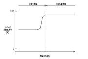
- the graph which shows the relationship between the wavelength of electromagnetic waves and the light ray transmittance in the cover of 1st Embodiment.
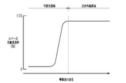
- the graph which shows the relationship between the wavelength of electromagnetic waves and light ray transmittance in the cover of 2nd Embodiment.
- near-infrared sensors 11 and covers 20 are attached to four corners (right front, left front, right rear, left rear) of the vehicle 10 in plan view. Only the cover 20 provided on the left front of the vehicle 10 is shown in FIG. Since the four near infrared sensors 11 (FIG. 2) and the cover 20 are the same, only the near infrared sensors 11 and the cover 20 provided on the left front of the vehicle 10 will be described below, and the other three locations The description about the near-infrared sensor 11 and the cover 20 is omitted.
- the near infrared sensor 11 has a substantially rectangular parallelepiped shape and is fixed to the body of the vehicle 10.
- the cover 20 has a plate shape having a five-layer structure, and is fixed to the body of the vehicle 10 as an exterior member of the vehicle 10.
- the cover 20 is arranged to cover the near-infrared sensor 11 from the front of the transmission direction of the near-infrared light transmitted from the near-infrared sensor 11 (indicated by an open arrow in FIG. 2).
- the near infrared rays transmitted from the near infrared sensor 11 are transmitted in the thickness direction of the cover 20 (left and right direction in FIG. 2).
- the cover 20 includes, in order from the side corresponding to the outside of the vehicle (left side in FIG. 2), the reflection suppressing layer 21, the hard coat layer 22, the base material 23, the glitter decorative layer 24, and the reflection suppressing layer 25.
- the thickness of the reflection suppressing layers 21 and 25, the thickness of the hard coat layer 22, and the thickness of the bright decorative layer 24 are shown exaggerating the actual thickness in order to facilitate understanding.
- the reflection suppressing layer 21 is formed of silicon dioxide (so-called mesoporous silica) having uniform and regular pores.
- the reflection suppressing layer 21 suppresses the reflection of visible light (such as sunlight) incident on the cover 20 from the side corresponding to the outside of the vehicle (left side in FIG. 2).
- the hard coat layer 22 is made of a hard resin material.
- the hard coat layer 22 suppresses damage to the cover 20 due to contact with an obstacle such as a stepping stone.
- the hard coat layer 22 is formed by applying a surface treatment agent (for example, an acrylate hard coat agent) to the surface of the substrate 23.
- the substrate 23 is formed of a transparent resin material (polycarbonate).
- the base material 23 constitutes a main part of the cover 20 in the thickness direction of the cover 20.
- the bright decoration layer 24 is formed by alternately laminating a dielectric thin film formed of a high refractive index material and a dielectric thin film formed of a relatively low refractive index low refractive index material. It is composed of a dielectric multilayer film.
- titanium dioxide [TiO 2 ] is used as the high refractive index material.
- Silicon dioxide [SiO 2 ] is used as the low refractive index material in the present embodiment.
- a total of 25 dielectric thin films are stacked.
- alternately stacking dielectric thin films having a high refractive index and dielectric thin films having a low refractive index results in a reflective thin film having high reflectance.
- a slight reflection occurs at the boundary between adjacent dielectric thin films inside the dielectric multilayer film.
- the thickness of all the dielectric thin films of the dielectric multilayer film is adjusted to an optical path length (refractive index n ⁇ film thickness d) of ⁇ / 4. Therefore, the phases of the lights reflected by the respective layers of the dielectric multilayer film are aligned, and the lights reflected by the respective layers of the dielectric multilayer film strengthen each other. On the other hand, the lights traveling in the transmission direction with multiple reflection in the dielectric multilayer cancel each other.
- the dielectric multilayer film hardly absorbs light, the transmittance and the reflectance can be set over a wide range.
- the bright decorative layer 24 reflects a part of incident visible light and transmits most of the remaining light while entering Transmit most of the
- the wavelength of the incident visible light is 0.36 ⁇ m to 0.83 ⁇ m
- the wavelength of the incident near-infrared light is 0.83 ⁇ m to 3.00 ⁇ m.
- the cover 20 is configured such that the light transmittance of near-infrared light is higher than the light transmittance of visible light due to the characteristics of the bright decorative layer 24. Specifically, as shown in FIG. 3, while the light transmittance of visible light (specifically, sunlight having a wavelength of 0.40 ⁇ m to 0.70 ⁇ m) is “50%”, the light transmittance of near infrared rays is The characteristics (material, structure, shape, etc.) of each layer of the cover 20 are determined so that “90%” is obtained. In the present embodiment, more specifically, the cover 20 is configured such that the average value of the light transmittance in the wavelength region of sunlight (0.40 ⁇ m to 0.70 ⁇ m) is “50%”.
- the reflection suppressing layer 25 is formed of mesoporous silica, similarly to the reflection suppressing layer 21.
- the reflection suppressing layer 25 suppresses the near infrared rays transmitted from the near infrared sensor 11 from being reflected by the cover 20.
- a light emitting unit 30 is disposed on the side closer to the near infrared sensor 11 (right side in FIG. 2) than the cover 20 in the vehicle 10.
- the light emitting unit 30 has an annular case 31 and a plurality of light emitting diodes 32 (only two are shown in FIG. 2).
- the case 31 extends along the outer edge of the cover 20.
- the light emitting diode 32 is fixed to the bottom of the case 31.
- the case 31 extends so as to open toward the outer edge of the cover 20 and is fixed to the body of the vehicle 10.
- the light emitting diodes 32 are disposed inside the case 31 so as to be spaced along the outer edge of the cover 20.
- the light emitting unit 30 can emit visible light toward the surface (rear surface 20A) of the cover 20 on the side near the near infrared sensor 11 by lighting the light emitting diode 32 inside the case 31.
- the vehicle 10 is provided with an electronic control unit 12 mainly composed of, for example, a microcomputer.
- an electronic control unit 12 Connected to the electronic control unit 12 are various sensors for detecting the driving state of the vehicle 10, operation switches for operating the on-vehicle devices, and the light emitting diodes 32 of the light emitting unit 30.
- the electronic control unit 12 takes in the output signals of various sensors and operation switches, performs various calculations based on the signals, and operates (lights on / off the light emitting unit 30 (specifically, the light emitting diode 32) based on the calculation results. Control the light).
- the light emitting diode 32 may be lighted in conjunction with the lighting of the headlight of the vehicle 10. For example, the light emitting diode 32 is turned on when the headlight is turned on, and the light emitting diode 32 is turned off when the headlight is turned off.
- the light emitting diode 32 may be lit in conjunction with the execution of the automatic driving. For example, the light emitting diode 32 is turned off when the automatic driving is not performed, while the light emitting diode 32 is lit when the automatic driving is performed.
- the vehicle 10 receives the near infrared light from the front in the transmission direction of the near infrared light (indicated by white arrows in FIGS. 4 and 5) transmitted from the near infrared light sensor 11.
- a cover 20 is provided to cover the sensor 11.
- the near-infrared light transmittance of the cover 20 is set relatively high (90% in the present embodiment). Therefore, the near infrared rays emitted from the near infrared sensor 11 and the near infrared rays reflected back from the obstacle pass through the cover 20.
- the cover 20 can be inhibited from inhibiting transmission and reception of near infrared light by the near infrared sensor 11, the function of detecting an obstacle by the near infrared sensor 11 can be secured.
- the light transmittance of visible light (shown by the black arrows in FIGS. 4 and 5) is set to be relatively low (in the present embodiment, sunlight) Light transmittance of “50%”).
- the light emitting diode 32 When the light emitting diode 32 is turned on and visible light is emitted from the light emitting unit 30 toward the back surface 20A of the cover 20, as indicated by a black arrow in FIG. 5, a part of the irradiated visible light Transmits through the bright decoration layer 24 to illuminate the surface of the cover 20 including the same bright decoration layer 24 on the side corresponding to the outside of the vehicle. Therefore, in the present embodiment, the light emitting diode 32 is turned on at an arbitrary timing such as night driving or automatic driving of the vehicle 10 to light the cover 20 and further improve the design of the portion where the cover 20 is disposed. be able to.
- the bright decorative layer 24 is disposed closer to the near infrared sensor 11 than the base material 23, that is, on the side corresponding to the inside of the vehicle among the covers 20 having a multilayer structure. Therefore, when the bright decoration layer 24 is disposed farther from the near infrared sensor 11 than the base material 23 (that is, when the bright decoration layer 24 is disposed on the side corresponding to the vehicle exterior of the base material 23) In comparison, the cover 20 can be configured so that the bright decorative layer 24 is not easily damaged by the contact of an obstacle from the outside of the vehicle. Therefore, the fall of the designability resulting from damage to the brightness decoration layer 24, and the fall of the detection precision of an obstruction can be suppressed suitably.
- the plate-like cover 20 is disposed in the vehicle 10 so that near-infrared rays transmitted from the near-infrared sensor 11 transmit in the thickness direction of the cover 20.
- a part in the thickness direction of the cover 20 is configured by the bright decorative layer 24 that reflects a part of visible light and transmits near infrared rays.
- the cover 20 is configured such that the near infrared light transmittance is higher than the sunlight light transmittance.
- the light emitting unit 30 that irradiates the cover 20 with visible light is provided. Therefore, the design can be further improved while securing the detection function of the near-infrared sensor 11.
- the bright decorative layer 24 of the cover 20 is disposed closer to the near infrared sensor 11 than the base material 23 (ie, the side of the base 23 corresponding to the inner side of the base material 23). . Therefore, the fall of the designability resulting from damage to the brightness decoration layer 24, and the fall of the detection precision of an obstruction can be suppressed.
- the light emitting unit 30 is disposed so as to irradiate visible light to the surface of the bright decorative layer 24 on the side near the near infrared sensor 11. Since a part of the visible light emitted from the light emitting unit 30 passes through the bright decoration layer 24, the bright decoration layer 24 can be illuminated by the transmitted visible light.
- the present embodiment mainly differs from the first embodiment in the arrangement position of the light emitting unit with respect to the cover.
- the light emitting unit 30 (see FIG. 2) is arranged to emit visible light to the surface of the bright decorative layer 24 closer to the near infrared sensor 11.
- the light emitting portion is arranged to irradiate visible light to the surface of the bright decorative layer far from the near infrared sensor 11.
- the cover 40 has a plate shape having a five-layer structure, and is fixed to the body of the vehicle 10 as an exterior member of the vehicle 10.
- the cover 40 includes, in order from the side corresponding to the outside of the vehicle (left side in FIG. 6), the reflection suppressing layer 21, the hard coat layer 22, the base material 23, the glitter decorative layer 44, and the reflection suppressing layer 25.
- the thickness of the reflection suppressing layers 21 and 25, the thickness of the hard coat layer 22, and the thickness of the bright decorative layer 44 are shown exaggerating the actual thickness in order to facilitate understanding.
- the bright decorative layer 44 of the present embodiment is formed by alternately laminating a dielectric thin film formed of a high refractive index material and a dielectric thin film formed of a low refractive index material having a relatively low refractive index. It is comprised by the dielectric multilayer film formed by this.
- titanium dioxide [TiO 2 ] is used as the high refractive index material.
- Silicon dioxide [SiO 2 ] is used as the low refractive index material in the present embodiment.
- the bright decoration layer 44 reflects a part of incident visible light and transmits most of the remaining light, while transmitting most of the incident near-infrared light.
- the cover 40 is configured such that the light transmittance of near-infrared light is higher than the light transmittance of visible light due to the characteristics of the bright decoration layer 44.
- visible light specifically, sunlight having a wavelength of 0.40 ⁇ m to 0.70 ⁇ m
- the characteristics (material, structure, shape, etc.) of each layer of the cover 40 are determined such that the light transmittance of the light source of the invention becomes “5%” and the light transmittance of the near infrared light becomes “90%”.
- the cover 40 is configured such that the average value of the light transmittance in the wavelength region of sunlight (0.40 ⁇ m to 0.70 ⁇ m) is “5%”.
- the outer peripheral edge of the cover 40 is provided with an inclined portion 47 which is inclined so as to approach the near infrared sensor 11 (inclined toward the inside of the vehicle).
- a projecting portion 48 formed by projecting a part of the base material 23 in the outer peripheral direction is provided.
- the protrusion 48 extends in an annular manner around the entire circumference of the inclined portion 47.
- the vehicle 10 is provided with an annular light emitting portion 50 extending along the outer peripheral surface of the cover 40 (specifically, the tip of the annular protrusion 48).
- the light emitting unit 50 has an annular case 51 and a plurality of light emitting diodes 32 (only two are shown in FIG. 6).
- the case 51 extends along the end of the protrusion 48.
- the light emitting diode 32 is fixed to the bottom of the case 51.
- the case 51 extends so as to open toward the end of the projection 48 and is fixed to the body of the vehicle 10.
- the light emitting diodes 32 are disposed inside the case 51 so as to be spaced apart along the outer peripheral surface of the cover 40.
- the light emitting unit 50 turns on the light emitting diode 32 inside the case 51 to be directed to the inside of the base material 23 in the cover 40 via the projecting portion 48 and further from the near infrared sensor 11 in the bright decorative layer 44. Visible light can be emitted toward the side surface 44A.
- the near-infrared light is transmitted from the front of the transmission direction of the near-infrared light (indicated by white arrows in FIGS. 8 and 9) transmitted from the near-infrared sensor 11.
- a cover 40 is provided to cover the sensor 11.
- the near-infrared light transmittance of the cover 40 is set relatively high (90% in the present embodiment). Therefore, the near infrared rays irradiated from the near infrared sensor 11 and the near infrared rays reflected back from the obstacle pass through the cover 40.
- the cover 40 can be inhibited from inhibiting transmission and reception of near-infrared light by the near-infrared light sensor 11, the obstacle detection function by the near-infrared light sensor 11 is secured.
- the light transmittance of visible light (indicated by the black arrows in FIGS. 8 and 9) is set to be relatively low (in the present embodiment, sunlight) Light transmittance of “5%”).
- the light emitting diode 32 when the light emitting diode 32 is turned on and visible light is emitted from the light emitting unit 50 toward the cover 40, the visible light is projected from the projecting portion 48 and the base It reaches the surface 44A of the side (corresponding to the outside of the vehicle) far from the near-infrared sensor 11 of the bright decorative layer 44 through the material 23.
- the surface 44A on the side corresponding to the vehicle exterior of the bright decorative layer 44 the same surface 44A glows.
- the light emitting diode 32 is turned on at an arbitrary timing such as night driving or automatic driving of the vehicle 10 to light the cover 40 and further improve the design of the portion where the cover 40 is disposed. be able to.
- the light emitting unit 50 is disposed to emit visible light to the surface 44A on the side (the side corresponding to the outside of the vehicle) far from the near infrared sensor 11 in the bright decorative layer 44. Therefore, part of the visible light emitted from the light emitting unit 50 is reflected by the surface 44A on the side corresponding to the vehicle exterior of the light decoration layer 44, so that the light decoration layer 44 can be illuminated by the reflected visible light. it can.
- the above embodiments may be modified as follows.
- the design of the cover can be suitably enhanced by causing the glitter decorative layers 24 and 44 to shine.
- 10 and 11 show a specific example of such a cover device for a near-infrared sensor.
- the cover 60 has a plate shape having a five-layer structure.
- the configuration having the same function as that of the first embodiment (see FIG. 2) is denoted by the same reference numeral, and the detailed description thereof is omitted.
- the thickness of the reflection suppressing layers 21 and 25 and the thickness of the hard coat layer 22 and the thickness of the bright decorative layer 24 are shown exaggeratingly more than the actual thickness in order to facilitate understanding.
- the cover 60 includes, in order from the side corresponding to the outside of the vehicle (left side in FIG. 10), the reflection suppressing layer 21, the hard coat layer 22, the glitter decorative layer 24, the base material 23, and the reflection suppressing layer 25.
- the light emitting unit 30 is provided to emit visible light to the back surface of the cover 60.
- the cover 70 has a plate shape having a five-layer structure.
- the components having the same functions as those of the second embodiment (see FIG. 6) are denoted by the same reference numerals, and the detailed description thereof will be omitted.
- the thickness of the reflection suppressing layers 21 and 25, the thickness of the hard coat layer 22, and the thickness of the bright decorative layer 44 are shown exaggeratingly from the actual thickness in order to facilitate understanding.
- the cover 70 includes, in order from the side corresponding to the outside of the vehicle (left side in FIG. 11), the reflection suppressing layer 21, the hard coat layer 22, the glitter decorative layer 44, the base material 23, and the reflection suppressing layer 25.
- the light emitting unit 50 is provided to emit visible light to the end of the protrusion 48 disposed on the outer periphery of the cover 70. In this case, it is desirable to set the light transmittance of near-infrared light in the cover 70 to "90%" and the light transmittance of sunlight to "50%".
- the following effects can be obtained.
- the light emitting diode 32 When the light emitting diode 32 is turned on and visible light is emitted from the light emitting unit 50 toward the cover 70, the visible light passes through the inside of the substrate 23. Then, part of the visible light passing through the inside of the base material 23 passes through the bright decoration layer 44, whereby the surface on the side (left side in FIG. 11) of the bright decoration layer 44 corresponding to the outside of the vehicle shines. Therefore, it is possible to light the cover 70 by lighting the light emitting diode 32 at an arbitrary timing such as night driving or automatic driving of the vehicle, and to improve the design of the portion where the cover 70 is disposed.
- the high refractive index material and the low refractive index material used to form the dielectric thin film forming the bright decoration layers 24 and 44 can be arbitrarily changed.
- a high refractive index material aluminum oxide (Al 2 O 3 ), zirconium oxide (ZrO 2 ), or the like can be used.
- ZrO 2 zirconium oxide
- the low refractive index material zinc peroxide (ZnO 2 ), magnesium fluoride (MgF 2 ) or the like can be used.
- the light transmittance of near-infrared light and the light transmittance of visible light in the covers 20, 40, 60, and 70 can be arbitrarily changed. While increasing the light transmittance of near infrared rays to such an extent that the detection function of the near infrared sensor 11 is ensured, the light transmittance of near infrared rays is made visible light (specifically, visible light of a wavelength near the boundary with the near infrared region It may be made higher than the light transmittance of visible light in most wavelength regions except the above. The following points were found from the results of various experiments and simulations by the inventors.
- the rays of visible light in the above-mentioned most wavelength regions of the covers 20, 40, 60, 70 It is preferable to set the transmittance in the range of “5% to 50%”.
- the light emitting diodes 32 of the light emitting units 30 and 50 may be constantly lit. Instead of the light emitting diode 32, another light emitter such as an incandescent lamp can be used.
- the reflection suppressing layers 21 and 25 may be formed of any material other than mesoporous silica. Such materials include, for example, an antireflection film (so-called moth-eye film) having an eyelid structure, and a dielectric film composed of a single layer or multiple layers.
- the hard coat layer 22 may be omitted.
- the reflection suppressing layers 21 and 25 can be omitted.
- the substrate 23 may be formed of a translucent resin material.
- SYMBOLS 10 Vehicle, 11 ... Near-infrared sensor, 12 ... Electronic control unit, 20, 40, 60, 70 ... Cover, 20A ... Back surface, 21 ... Reflection suppression layer, 22 ... Hard-coat layer, 23 ... Base material, 24, 44 ... A light decoration layer, 44A: surface, 25: a reflection suppression layer, 30, 50: a light emitting portion, 31, 51: a case, 32: a light emitting diode, 44: a light decoration layer, 47: an inclined portion, 48: a protrusion .
Landscapes
- Physics & Mathematics (AREA)
- General Physics & Mathematics (AREA)
- Engineering & Computer Science (AREA)
- Optics & Photonics (AREA)
- Spectroscopy & Molecular Physics (AREA)
- Health & Medical Sciences (AREA)
- General Engineering & Computer Science (AREA)
- Pathology (AREA)
- Immunology (AREA)
- General Health & Medical Sciences (AREA)
- Biochemistry (AREA)
- Life Sciences & Earth Sciences (AREA)
- Chemical & Material Sciences (AREA)
- Analytical Chemistry (AREA)
- Computer Networks & Wireless Communication (AREA)
- Remote Sensing (AREA)
- Radar, Positioning & Navigation (AREA)
- Toxicology (AREA)
- Mechanical Engineering (AREA)
- Traffic Control Systems (AREA)
- Optical Radar Systems And Details Thereof (AREA)
- Vehicle Interior And Exterior Ornaments, Soundproofing, And Insulation (AREA)
- Non-Portable Lighting Devices Or Systems Thereof (AREA)
- Lighting Device Outwards From Vehicle And Optical Signal (AREA)
Abstract
近赤外線センサ用カバー装置において、板状のカバー(20)は、近赤外線センサ(11)から送信される近赤外線がカバー(20)の厚み方向に透過するように車両(10)に配置されている。カバー(20)の厚み方向における一部は、入射される可視光の一部を反射するとともに近赤外線を透過する光輝加飾層(24)によって構成されている。カバー(20)は、可視光の光線透過率よりも近赤外線の光線透過率が高くなるように構成されている。車両(10)には、カバー(20)に可視光を照射する発光部(30)が設けられている。
Description
本発明は、近赤外線センサから送信される近赤外線の送信方向の前方から、近赤外線センサを覆うように配置される近赤外線センサ用カバー装置に関するものである。
車両の分野では、近赤外線センサから近赤外線を車両周囲へ向けて送信し、先行車両や歩行者などを含む障害物に当たって反射された近赤外線を受信することで、障害物との間の距離および相対速度を検出する技術の開発が進められている。
障害物検出用のセンサが設けられた車両に、同センサから送信される信号の送信方向における前方から、同センサを覆うカバーを設けることが提案されている(例えば特許文献1参照)。特許文献1では、上記カバーとして、上記信号を透過する樹脂材料によって形成された板材が設けられている。このカバーは、上記信号を透過するので、障害物を検出する機能が確保される。そして、上記カバーを設けることによって、障害物検出用のセンサ(レーザーレーダーや超音波センサ)を車外から見えないように隠すことができる。これにより、車両の見栄えが向上する。
上記カバーには、車両の更なる意匠性の向上のために、単に近赤外線センサを車外から見えないように隠すだけでなく、同センサの配設部分の意匠性を向上させるような付加価値が求められている。
本発明は、そうした実情に鑑みてなされたものである。本発明の目的は、近赤外線センサの検出機能を確保しながら、意匠性の更なる向上を図ることのできる近赤外線センサ用カバー装置を提供することにある。
上記課題を解決するための近赤外線センサ用カバー装置は、近赤外線センサから送信される近赤外線の送信方向の前方から、前記近赤外線センサを覆うように配置される。前記近赤外線センサ用カバー装置は、板状のカバーと、発光部とを有する。前記カバーは、前記近赤外線センサから送信される近赤外線が前記カバーの厚み方向に透過するように車両に配置されている。前記カバーの前記厚み方向における一部は、入射される可視光の一部を反射するとともに近赤外線を透過する光輝加飾層によって構成されている。前記カバーは、可視光の光線透過率よりも近赤外線の光線透過率が高くなるように構成されている。前記発光部は、前記カバーに可視光を照射する。
上記構成によれば、近赤外線センサから送信される近赤外線の送信方向の前方から、近赤外線センサを覆うようにカバーが設けられている。しかしながら、同カバーの近赤外線の光線透過率は比較的高いため、カバーが近赤外線の送受信を阻害することが抑えられており、近赤外線センサによる障害物の検出機能を確保することができる。また、車両外部からカバーに太陽光(可視光)が入射された場合には、その可視光の一部が反射して同カバーが光る。このため、カバーの配設部分の意匠性を高くすることができる。加えて、発光部からカバーに可視光を照射することによって、照射された可視光の一部を透過(あるいは反射)させて同カバーの車両外部に対応する側を光らせることができ、カバーの配設部分の意匠性をさらに向上させることができる。このように、上記構成によれば、近赤外線センサの検出機能を確保しながら、意匠性の更なる向上を図ることができる。
上記装置において、前記カバーの可視光の光線透過率は、5%以上であり且つ50%以下であってもよい。
上記装置において、前記カバーの前記厚み方向における主要部は、透明または半透明の基材によって構成されており、前記光輝加飾層は前記基材よりも前記近赤外線センサの近くに配置されていてもよい。
上記装置において、前記カバーの前記厚み方向における主要部は、透明または半透明の基材によって構成されており、前記光輝加飾層は前記基材よりも前記近赤外線センサの近くに配置されていてもよい。
上記構成によれば、光輝加飾層が基材よりも近赤外線センサから遠くに配置された場合(すなわち、光輝加飾層が基材の車両外部に対応する側に配置された場合)と比較して、車両外部からの障害物の接触に対してカバーの光輝加飾層を傷つき難くすることができる。したがって、光輝加飾層が傷つくことに起因する意匠性の低下や障害物の検出精度の低下を抑えることができる。
上記装置において、前記カバーの前記厚み方向における主要部は、透明または半透明の基材によって構成されており、前記光輝加飾層は前記基材よりも前記近赤外線センサから遠くに配置されていてもよい。
上記構成によれば、光輝加飾層が基材の車両外部に対応する側に配置されるため、光輝加飾層が基材よりも近赤外線センサの近くに配置された場合(すなわち、光輝加飾層が基材の車両内部に対応する側に配置された場合)と比較して、光輝加飾層を車両外部から見え易くすることができる。そのため、光輝加飾層を光らせることによって、カバーの意匠性を好適に高くすることができる。
上記装置において、前記発光部は、前記光輝加飾層における前記近赤外線センサに近い側の面に前記可視光を照射するように配置されていてもよい。
上記構成によれば、発光部から照射された可視光の一部が光輝加飾層を透過するため、この透過する可視光によって光輝加飾層を光らせることができる。
上記構成によれば、発光部から照射された可視光の一部が光輝加飾層を透過するため、この透過する可視光によって光輝加飾層を光らせることができる。
上記装置において、前記発光部は、前記光輝加飾層における前記近赤外線センサから遠い側の面に前記可視光を照射するように配置されていてもよい。
上記構成によれば、発光部から照射された可視光の一部が光輝加飾層で反射するため、この反射する可視光によって光輝加飾層を光らせることができる。
上記構成によれば、発光部から照射された可視光の一部が光輝加飾層で反射するため、この反射する可視光によって光輝加飾層を光らせることができる。
本発明によれば、近赤外線センサの検出機能を確保しながら、意匠性の更なる向上を図ることができる。
(第1実施形態)
以下、近赤外線センサ用カバー装置の第1実施形態について説明する。
図1または2に示すように、車両10の平面視における四隅(右前方、左前方、右後方、左後方)にはそれぞれ、近赤外線センサ11およびカバー20が取り付けられている。図1には車両10の左前方に設けられたカバー20のみを示している。4箇所の近赤外線センサ11(図2)およびカバー20は同一のものであるため、以下では車両10の左前方に設けられた近赤外線センサ11およびカバー20のみを説明し、他の3箇所の近赤外線センサ11およびカバー20についての説明は割愛する。
以下、近赤外線センサ用カバー装置の第1実施形態について説明する。
図1または2に示すように、車両10の平面視における四隅(右前方、左前方、右後方、左後方)にはそれぞれ、近赤外線センサ11およびカバー20が取り付けられている。図1には車両10の左前方に設けられたカバー20のみを示している。4箇所の近赤外線センサ11(図2)およびカバー20は同一のものであるため、以下では車両10の左前方に設けられた近赤外線センサ11およびカバー20のみを説明し、他の3箇所の近赤外線センサ11およびカバー20についての説明は割愛する。
図2に示すように、近赤外線センサ11は略直方体形状であり、車両10のボディに固定されている。カバー20は、五層構造を有する板状をなしており、車両10の外装部材として同車両10のボディに固定されている。カバー20は、近赤外線センサ11から送信される近赤外線の送信方向(図2中に白抜きの矢印で示す)の前方から、近赤外線センサ11を覆うように配置されている。近赤外線センサ11から送信される近赤外線は、カバー20の厚み方向(図2の左右方向)に透過する。
カバー20は、車両外部に対応する側(図2の左側)から順に、反射抑制層21、ハードコート層22、基材23、光輝加飾層24、反射抑制層25を有する。図2では、理解を容易にするために、反射抑制層21,25の厚さやハードコート層22の厚さ、光輝加飾層24の厚さを実際の厚さよりも誇張して示している。
反射抑制層21は、均一で規則的な細孔を有する二酸化ケイ素(いわゆるメソポーラスシリカ)によって形成されている。反射抑制層21は、車両外部に対応する側(図2の左側)からカバー20に入射される可視光(太陽光など)の反射を抑える。
ハードコート層22は、硬質の樹脂材料からなる。ハードコート層22は、飛び石などの障害物との接触によるカバー20の傷つきを抑制する。ハードコート層22は、基材23の表面に表面処理剤(例えば、アクリレート系のハードコート剤)を塗布することによって形成される。
基材23は透明な樹脂材料(ポリカーボネート)によって形成されている。基材23は、カバー20の厚み方向における、カバー20の主要部を構成している。
光輝加飾層24は、高屈折率材料で形成された誘電体薄膜と、相対的に低い屈折率を有する低屈折率材料で形成された誘電体薄膜とを交互に積層することによって形成された誘電体多層膜によって構成されている。高屈折率材料として、本実施形態では、二酸化チタン[TiO2]が用いられている。低屈折率材料として、本実施形態では、二酸化ケイ素[SiO2]が用いられている。本実施形態では、合計25層の誘電体薄膜が積層されている。
光輝加飾層24は、高屈折率材料で形成された誘電体薄膜と、相対的に低い屈折率を有する低屈折率材料で形成された誘電体薄膜とを交互に積層することによって形成された誘電体多層膜によって構成されている。高屈折率材料として、本実施形態では、二酸化チタン[TiO2]が用いられている。低屈折率材料として、本実施形態では、二酸化ケイ素[SiO2]が用いられている。本実施形態では、合計25層の誘電体薄膜が積層されている。
一般に、高い屈折率を有する誘電体薄膜と低い屈折率を有する誘電体薄膜とを交互に積み重ねると、高い反射率を有する反射薄膜が得られる。誘電体多層膜の内部において隣り合う誘電体薄膜の境界では、僅かな反射が生ずる。誘電体多層膜の全ての誘電体薄膜の厚さは、λ/4の光路長(屈折率n×膜厚d)に調整されている。そのため、誘電体多層膜の各層で反射した光の位相が揃い、誘電体多層膜の各層で反射した光は互いに強め合う。その一方で、誘電体多層膜において多重反射して透過方向に進む光は、互いに打ち消し合う。誘電体多層膜では光が吸収されることが殆どないため、透過率および反射率を広範囲で設定することができる。本実施形態では、こうした誘電体多層膜を用いることによって、光輝加飾層24が、入射される可視光の一部を反射するとともに残りの殆どの光を透過させる一方で、入射される近赤外線の殆どを透過させる。ここで、入射される可視光の波長は0.36μm~0.83μmであり、入射される近赤外線の波長は0.83μm~3.00μmである。
本実施形態において、カバー20は、こうした光輝加飾層24の特性によって、可視光の光線透過率よりも近赤外線の光線透過率が高くなるように構成されている。具体的には、図3に示すように、可視光(詳しくは、0.40μm~0.70μmの波長を有する太陽光)の光線透過率が「50%」になるとともに近赤外線の光線透過率が「90%」になるように、カバー20の各層の特性(材質や構造、形状など)が定められている。本実施形態では、より詳しくは、太陽光の波長領域(0.40μm~0.70μm)における光線透過率の平均値が「50%」となるように、カバー20が構成されている。
図2に示すように、反射抑制層25は、前記反射抑制層21と同様に、メソポーラスシリカによって形成されている。反射抑制層25は、近赤外線センサ11から送信された近赤外線がカバー20において反射することを抑える。
車両10におけるカバー20よりも近赤外線センサ11に近い側(図2の右側)には、発光部30が配置されている。発光部30は、環状のケース31と、複数の発光ダイオード32(図2には二つのみ図示)とを有している。ケース31は、カバー20の外縁に沿って延びている。発光ダイオード32は、ケース31の底部に固定されている。ケース31は、カバー20の外縁に向けて開口するように延びており、車両10のボディに固定されている。発光ダイオード32は、カバー20の外縁に沿って間隔を置いて並ぶように、ケース31の内部に配置されている。発光部30は、ケース31内部の発光ダイオード32を点灯させることによって、カバー20における近赤外線センサ11に近い側の面(裏面20A)に向けて可視光を照射することができる。
車両10には、例えば主にマイクロコンピュータによって構成される電子制御装置12が設けられている。電子制御装置12には、車両10の運転状態を検出するための各種センサ、車載機器を操作するための操作スイッチ、発光部30の発光ダイオード32などが接続されている。電子制御装置12は、各種センサや操作スイッチの出力信号を取り込み、同信号に基づき各種の演算を行い、その演算結果をもとに発光部30(詳しくは、発光ダイオード32)の作動(点灯/消灯)を制御する。
発光部30の作動制御では、車両10の前照灯の点灯に連動して発光ダイオード32を点灯させてもよい。例えば、前照灯の点灯時には発光ダイオード32を点灯させる一方で、同前照灯の消灯時には発光ダイオード32を消灯させる。自動運転機能を有する車両における発光部30の作動制御では、自動運転の実行に連動して発光ダイオード32を点灯させてもよい。例えば、自動運転が実行されないときには発光ダイオード32を消灯させる一方で、自動運転が実行されるときには発光ダイオード32を点灯させる。
以下、本実施形態の近赤外線センサ用カバー装置による作用効果について説明する。
図4および図5に示すように、車両10には、近赤外線センサ11から送信される近赤外線(図4中および図5中に白抜きの矢印で示す)の送信方向の前方から、近赤外線センサ11を覆うようにカバー20が設けられている。カバー20の近赤外線の光線透過率は、比較的高く設定されている(本実施形態では90%)。そのため、近赤外線センサ11から照射される近赤外線や、障害物に反射して戻ってくる近赤外線がカバー20を透過する。このように、近赤外線センサ11による近赤外線の送受信をカバー20が阻害することが抑えられるため、近赤外線センサ11による障害物の検出機能は確保される。
図4および図5に示すように、車両10には、近赤外線センサ11から送信される近赤外線(図4中および図5中に白抜きの矢印で示す)の送信方向の前方から、近赤外線センサ11を覆うようにカバー20が設けられている。カバー20の近赤外線の光線透過率は、比較的高く設定されている(本実施形態では90%)。そのため、近赤外線センサ11から照射される近赤外線や、障害物に反射して戻ってくる近赤外線がカバー20を透過する。このように、近赤外線センサ11による近赤外線の送受信をカバー20が阻害することが抑えられるため、近赤外線センサ11による障害物の検出機能は確保される。
その一方で、本実施形態のカバー20では、可視光(図4中および図5中に黒塗りの矢印で示す)の光線透過率が比較的低く設定されている(本実施形態では、太陽光の光線透過率は「50%」である)。
そのため、図4中に黒塗りの矢印で示すように、車両外部からカバー20に可視光(太陽光)が入射された場合には、その太陽光の一部が光輝加飾層24の車両外部に対応する側の面で反射する。これにより、車両外部から近赤外線センサ11を見え難くすることができる。このため、近赤外線センサ11がむき出しの状態で車両10に取り付けられる場合と比べて、近赤外線センサ11の配設部分の見栄えを良くして意匠性の向上を図ることができる。加えて、このとき、太陽光の反射を利用してカバー20を光らせることができるため、カバー20の配設部分の意匠性をさらに高くすることができる。可視光(太陽光)の反射時におけるカバー20の色と、同カバー20の周辺に配置される外装部材(詳しくは、バンパー)の色とを同一にすることによって、カバー20を目立たなくすることもできる。
図5中に黒塗りの矢印で示すように、発光ダイオード32が点灯されて発光部30からカバー20の裏面20Aに向けて可視光が照射された場合には、照射された可視光の一部が光輝加飾層24を透過して、同光輝加飾層24を含むカバー20の車両外部に対応する側の面を光らせる。したがって、本実施形態では、車両10の夜間運転時や自動運転時などの任意のタイミングで発光ダイオード32を点灯することによって、カバー20を光らせ、カバー20の配設部分の意匠性をさらに向上させることができる。
本実施形態のカバー20では、光輝加飾層24が基材23よりも近赤外線センサ11の近くに、すなわち多層構造のカバー20の中でも車両内部に対応する側に配置されている。そのため、光輝加飾層24が基材23よりも近赤外線センサ11から遠くに配置された場合(すなわち、光輝加飾層24が基材23の車両外部に対応する側に配置された場合)と比較して、車両外部からの障害物の接触に対して光輝加飾層24が傷つき難いように、カバー20を構成することができる。したがって、光輝加飾層24が傷つくことに起因する意匠性の低下や障害物の検出精度の低下を好適に抑えることができる。
以上説明したように、本実施形態によれば、以下に記載する効果が得られる。
(1)板状のカバー20が、近赤外線センサ11から送信される近赤外線がカバー20の厚み方向において透過するように、車両10に配置されている。カバー20における厚み方向の一部は、可視光の一部を反射するとともに近赤外線を透過する光輝加飾層24によって構成されている。カバー20は、太陽光の光線透過率よりも近赤外線の光線透過率が高くなるように構成されている。加えて、カバー20に可視光を照射する、発光部30が設けられている。そのため、近赤外線センサ11の検出機能を確保しながら、意匠性の更なる向上を図ることができる。
(1)板状のカバー20が、近赤外線センサ11から送信される近赤外線がカバー20の厚み方向において透過するように、車両10に配置されている。カバー20における厚み方向の一部は、可視光の一部を反射するとともに近赤外線を透過する光輝加飾層24によって構成されている。カバー20は、太陽光の光線透過率よりも近赤外線の光線透過率が高くなるように構成されている。加えて、カバー20に可視光を照射する、発光部30が設けられている。そのため、近赤外線センサ11の検出機能を確保しながら、意匠性の更なる向上を図ることができる。
(2)カバー20の光輝加飾層24が、基材23よりも近赤外線センサ11の近くに(すなわち、光輝加飾層24が基材23の車両内部に対応する側に)配置されている。そのため、光輝加飾層24が傷つくことに起因する意匠性の低下や障害物の検出精度の低下を抑えることができる。
(3)発光部30は、光輝加飾層24における近赤外線センサ11に近い側の面に可視光を照射するように配置されている。発光部30から照射された可視光の一部が光輝加飾層24を透過するため、この透過する可視光によって光輝加飾層24を光らせることができる。
(第2実施形態)
以下、近赤外線センサ用カバー装置の第2実施形態について、第1実施形態との相違点を中心に説明する。以下では第1実施形態と同一機能の構成には同一の符号を付して示し、その詳細な説明は割愛する。
以下、近赤外線センサ用カバー装置の第2実施形態について、第1実施形態との相違点を中心に説明する。以下では第1実施形態と同一機能の構成には同一の符号を付して示し、その詳細な説明は割愛する。
本実施形態は主に、カバーに対する発光部の配設位置が先の第1実施形態と異なる。第1実施形態では、発光部30(図2参照)は、光輝加飾層24の近赤外線センサ11に近い側の面に可視光を照射するように配置されている。これに対して、本実施形態では、発光部は、光輝加飾層の近赤外線センサ11から遠い側の面に可視光を照射するように配置されている。
以下、本実施形態の近赤外線センサ用カバー装置について詳しく説明する。
図6に示すように、カバー40は五層構造を有する板状をなしており、車両10の外装部材として同車両10のボディに固定されている。カバー40は、車両外部に対応する側(図6の左側)から順に、反射抑制層21、ハードコート層22、基材23、光輝加飾層44、反射抑制層25を有する。図6では、理解を容易にするために、反射抑制層21,25の厚さやハードコート層22の厚さ、光輝加飾層44の厚さを実際の厚さよりも誇張して示している。
図6に示すように、カバー40は五層構造を有する板状をなしており、車両10の外装部材として同車両10のボディに固定されている。カバー40は、車両外部に対応する側(図6の左側)から順に、反射抑制層21、ハードコート層22、基材23、光輝加飾層44、反射抑制層25を有する。図6では、理解を容易にするために、反射抑制層21,25の厚さやハードコート層22の厚さ、光輝加飾層44の厚さを実際の厚さよりも誇張して示している。
本実施形態の光輝加飾層44は、高屈折率材料で形成された誘電体薄膜と、相対的に低い屈折率を有する低屈折率材料で形成された誘電体薄膜とを交互に積層することによって形成された誘電体多層膜によって構成されている。高屈折率材料として、本実施形態では、二酸化チタン[TiO2]が用いられている。低屈折率材料として、本実施形態では、二酸化ケイ素[SiO2]が用いられている。光輝加飾層44は、入射される可視光の一部を反射するとともに残りの殆どの光を透過させる一方で、入射される近赤外線の殆どを透過させる。
本実施形態では、カバー40は、こうした光輝加飾層44の特性によって、可視光の光線透過率よりも近赤外線の光線透過率が高くなるように構成されている。具体的には、図7に示すように、カバー40(詳しくは、光輝加飾層44が設けられた部分)において、可視光(詳しくは、0.40μm~0.70μmの波長を有する太陽光)の光線透過率が「5%」になるとともに近赤外線の光線透過率が「90%」になるように、カバー40の各層の特性(材質や構造、形状など)が定められている。本実施形態では、より詳しくは、太陽光の波長領域(0.40μm~0.70μm)における光線透過率の平均値が「5%」となるように、カバー40が構成されている。
カバー40の外周縁には、近赤外線センサ11に近づくように傾斜した(車両内部に向かって傾斜した)傾斜部47が設けられている。傾斜部47の外周には、基材23の一部を外周方向に突出させることによって形成された突出部48が設けられている。突出部48は、傾斜部47の周囲全周に渡って環状の態様で延びている。
車両10には、カバー40の外周面(詳しくは、環状の突出部48の突端)に沿って延びる環状の発光部50が配置されている。発光部50は、環状のケース51と、複数の発光ダイオード32(図6には二つのみ図示)とを有している。ケース51は、突出部48の突端に沿って延びている。発光ダイオード32は、ケース51の底部に固定されている。ケース51は、突出部48の突端に向けて開口するように延びており、車両10のボディに固定されている。発光ダイオード32は、カバー40の外周面に沿って間隔を置いて並ぶように、ケース51の内部に配置されている。
発光部50は、ケース51内部の発光ダイオード32を点灯させることによって、突出部48を介して、カバー40における基材23の内部に向けて、ひいては光輝加飾層44における近赤外線センサ11から遠い側の面44Aに向けて、可視光を照射することができる。
以下、本実施形態の近赤外線センサ用カバー装置による作用効果について説明する。
図8および図9に示すように、本実施形態では、近赤外線センサ11から送信される近赤外線(図8中および図9中に白抜きの矢印で示す)の送信方向の前方から、近赤外線センサ11を覆うようにカバー40が設けられている。カバー40の近赤外線の光線透過率は、比較的高く設定されている(本実施形態では90%)。そのため、近赤外線センサ11から照射される近赤外線や、障害物に反射して戻ってくる近赤外線がカバー40を透過する。このように、近赤外線センサ11による近赤外線の送受信をカバー40が阻害することが抑えられるため、近赤外線センサ11による障害物の検出機能は確保される。
図8および図9に示すように、本実施形態では、近赤外線センサ11から送信される近赤外線(図8中および図9中に白抜きの矢印で示す)の送信方向の前方から、近赤外線センサ11を覆うようにカバー40が設けられている。カバー40の近赤外線の光線透過率は、比較的高く設定されている(本実施形態では90%)。そのため、近赤外線センサ11から照射される近赤外線や、障害物に反射して戻ってくる近赤外線がカバー40を透過する。このように、近赤外線センサ11による近赤外線の送受信をカバー40が阻害することが抑えられるため、近赤外線センサ11による障害物の検出機能は確保される。
その一方で、本実施形態のカバー40では、可視光(図8中および図9中に黒塗りの矢印で示す)の光線透過率が比較的低く設定されている(本実施形態では、太陽光の光線透過率は「5%」である)。
そのため、図8中に黒塗りの矢印で示すように、車両外部からカバー40に可視光(太陽光)が入射された場合には、その太陽光の一部が光輝加飾層44の車両外部に対応する側の面44Aで反射する。これにより、車両外部から近赤外線センサ11を見え難くすることができる。このため、近赤外線センサ11がむき出しの状態で車両10に取り付けられる場合と比べて、近赤外線センサ11の配設部分の見栄えを良くして意匠性の向上を図ることができる。加えて、このとき、太陽光の反射を利用してカバー40を光らせることができるため、カバー40の配設部分の意匠性をさらに高くすることができる。
さらに、図9中に黒塗りの矢印で示すように、発光ダイオード32が点灯されて発光部50からカバー40に向けて可視光が照射された場合には、その可視光が突出部48および基材23を介して光輝加飾層44の近赤外線センサ11から遠い側(車両外部に対応する側)の面44Aに到達する。その到達した可視光の一部が光輝加飾層44の車両外部に対応する側の面44Aで反射することによって、同面44Aが光る。加えて、この場合には、照射された可視光が導光体として作用する基材23の内部を通過するため、その通過に際して同基材23が光る。したがって、本実施形態では、車両10の夜間運転時や自動運転時などの任意のタイミングで発光ダイオード32を点灯することによって、カバー40を光らせ、カバー40の配設部分の意匠性をさらに向上させることができる。
以上説明したように、本実施形態によれば、先の(1)および(2)に記載の効果に準じた効果に加えて、以下の(4)に記載の効果が得られる。
(4)発光部50は、光輝加飾層44における近赤外線センサ11から遠い側(車両外部に対応する側)の面44Aに可視光を照射するように配置されている。そのため、発光部50から照射された可視光の一部が光輝加飾層44の車両外部に対応する側の面44Aで反射するため、この反射する可視光によって光輝加飾層44を光らせることができる。
(4)発光部50は、光輝加飾層44における近赤外線センサ11から遠い側(車両外部に対応する側)の面44Aに可視光を照射するように配置されている。そのため、発光部50から照射された可視光の一部が光輝加飾層44の車両外部に対応する側の面44Aで反射するため、この反射する可視光によって光輝加飾層44を光らせることができる。
(他の実施形態)
なお、上記各実施形態は、以下のように変更して実施してもよい。
・光輝加飾層24,44が、基材23よりも近赤外線センサ11から遠くに(すなわち、光輝加飾層24,44が基材23の車両外部に対応する側に)配置されたカバーを採用してもよい。こうした構成によれば、光輝加飾層24,44が基材23の車両外部に対応する側に配置されるため、光輝加飾層24,44が基材23よりも近赤外線センサ11の近くに配置された場合(すなわち、光輝加飾層24,44が基材23の車両内部に対応する側に配置された場合)と比較して、光輝加飾層24,44を車両外部から見え易くすることができる。そのため、光輝加飾層24,44を光らせることによって、カバーの意匠性を好適に高くすることができる。図10および図11は、そうした近赤外線センサ用カバー装置の具体例を示している。
図10に示す例では、カバー60が五層構造を有する板状をなしている。以下では第1実施形態(図2参照)と同一機能の構成には同一の符号を付して示し、その詳細な説明は割愛する。図10では、理解を容易にするために、反射抑制層21,25の厚さやハードコート層22の厚さ、光輝加飾層24の厚さを実際の厚さよりも誇張して示している。カバー60は、車両外部に対応する側(図10の左側)から順に、反射抑制層21、ハードコート層22、光輝加飾層24、基材23、反射抑制層25を有する。発光部30は、カバー60の裏面に可視光を照射するように設けられている。この場合には、カバー60における近赤外線の光線透過率を「90%」に設定し、太陽光の光線透過率を「50%」に設定することが望ましい。こうした構成によれば、先の(1)および(3)に記載の効果に準じた効果が得られる。
図11に示す例では、カバー70が五層構造を有する板状をなしている。以下では第2実施形態(図6参照)と同一機能の構成には同一の符号を付して示し、その詳細な説明は割愛する。図11では、理解を容易にするために、反射抑制層21,25の厚さやハードコート層22の厚さ、光輝加飾層44の厚さを実際の厚さよりも誇張して示している。カバー70は、車両外部に対応する側(図11の左側)から順に、反射抑制層21、ハードコート層22、光輝加飾層44、基材23、反射抑制層25を有する。発光部50は、カバー70の外周に配置された突出部48の突端に可視光を照射するように設けられている。この場合には、カバー70における近赤外線の光線透過率を「90%」に設定し、太陽光の光線透過率を「50%」に設定することが望ましい。
こうした構成によれば、先の(1)に記載の効果に準じた効果に加えて、次の作用効果が得られる。発光ダイオード32が点灯されて発光部50からカバー70に向けて可視光が照射された場合には、その可視光が基材23の内部を通過する。そして、基材23内部を通過する可視光の一部が光輝加飾層44を透過することによって、光輝加飾層44の車両外部に対応する側(図11の左側)の面が光る。したがって、車両の夜間運転時や自動運転時などの任意のタイミングで発光ダイオード32を点灯することによって、カバー70を光らせ、カバー70の配設部分の意匠性を向上させることができる。
・光輝加飾層24,44を構成する誘電体薄膜の形成に用いられる高屈折率材料や低屈折率材料は、任意に変更することができる。高屈折率材料としては、酸化アルミニウム(Al2O3)や酸化ジルコニウム(ZrO2)などを用いることができる。低屈折率材料としては、過酸化亜鉛(ZnO2)やフッ化マグネシウム(MgF2)などを用いることができる。
・カバー20,40,60,70における近赤外線の光線透過率や可視光の光線透過率は、任意に変更することができる。近赤外線センサ11の検出機能が確保される程度に近赤外線の光線透過率を高くするとともに、近赤外線の光線透過率を可視光(詳しくは、近赤外線領域との境界付近の波長の可視光を除く、殆どの波長領域における可視光)の光線透過率よりも高くすればよい。発明者等による各種の実験やシミュレーションの結果から次の事項が分かった。近赤外線センサ11の検出機能を確保しながらカバー20,40,60,70の意匠性を向上させるためには、カバー20,40,60,70における、上述した殆どの波長領域における可視光の光線透過率を、「5%~50%」の範囲に設定することが好ましい。
・発光部30,50の発光ダイオード32を常時点灯させるようにしてもよい。
・発光ダイオード32に代えて、白熱灯等の他の発光体を用いることができる。
・反射抑制層21,25を、メソポーラスシリカ以外の任意の材料によって形成するようにしてもよい。そうした材料としては、例えば蛾の目構造を有する反射防止フィルム(いわゆるモスアイフィルム)や、単層または多層から構成される誘電体膜などがある。
・発光ダイオード32に代えて、白熱灯等の他の発光体を用いることができる。
・反射抑制層21,25を、メソポーラスシリカ以外の任意の材料によって形成するようにしてもよい。そうした材料としては、例えば蛾の目構造を有する反射防止フィルム(いわゆるモスアイフィルム)や、単層または多層から構成される誘電体膜などがある。
・ハードコート層22を省略してもよい。
・反射抑制層21,25を省略することができる。
・基材23の形成材料として、ポリメタクリル酸メチル(PMMA)やシクロオレフィンポリマー(COP)を採用することができる。基材23を半透明な樹脂材料によって形成してもよい。
・反射抑制層21,25を省略することができる。
・基材23の形成材料として、ポリメタクリル酸メチル(PMMA)やシクロオレフィンポリマー(COP)を採用することができる。基材23を半透明な樹脂材料によって形成してもよい。
10…車両、11…近赤外線センサ、12…電子制御装置、20,40,60,70…カバー、20A…裏面、21…反射抑制層、22…ハードコート層、23…基材、24,44…光輝加飾層、44A…面、25…反射抑制層、30,50…発光部、31,51…ケース、32…発光ダイオード、44…光輝加飾層、47…傾斜部、48…突出部。
Claims (6)
- 近赤外線センサから送信される近赤外線の送信方向の前方から、前記近赤外線センサを覆うように配置される近赤外線センサ用カバー装置であって、前記近赤外線センサ用カバー装置は、
板状のカバーであって、前記カバーは、前記近赤外線センサから送信される近赤外線が前記カバーの厚み方向に透過するように車両に配置され、前記カバーの前記厚み方向における一部は、入射される可視光の一部を反射するとともに近赤外線を透過する光輝加飾層によって構成されており、前記カバーは、可視光の光線透過率よりも近赤外線の光線透過率が高くなるように構成されている、カバーと、
前記カバーに可視光を照射する発光部と、
を有する近赤外線センサ用カバー装置。 - 前記カバーの可視光の光線透過率は、5%以上であり且つ50%以下である
請求項1に記載の近赤外線センサ用カバー装置。 - 前記カバーの前記厚み方向における主要部は、透明または半透明の基材によって構成されており、
前記光輝加飾層は前記基材よりも前記近赤外線センサの近くに配置されている
請求項1または2に記載の近赤外線センサ用カバー装置。 - 前記カバーの前記厚み方向における主要部は、透明または半透明の基材によって構成されており、
前記光輝加飾層は前記基材よりも前記近赤外線センサから遠くに配置されている
請求項1または2に記載の近赤外線センサ用カバー装置。 - 前記発光部は、前記光輝加飾層における前記近赤外線センサに近い側の面に前記可視光を照射するように配置されている
請求項1~4のいずれか一項に記載の近赤外線センサ用カバー装置。 - 前記発光部は、前記光輝加飾層における前記近赤外線センサから遠い側の面に前記可視光を照射するように配置されている
請求項1~4のいずれか一項に記載の近赤外線センサ用カバー装置。
Priority Applications (3)
| Application Number | Priority Date | Filing Date | Title |
|---|---|---|---|
| EP18858249.8A EP3663814B1 (en) | 2017-09-22 | 2018-08-20 | Cover device for near-infrared sensors |
| US16/640,167 US11385176B2 (en) | 2017-09-22 | 2018-08-20 | Cover device for near-infrared sensors |
| CN201880059952.7A CN111095049B (zh) | 2017-09-22 | 2018-08-20 | 用于近红外传感器的盖装置 |
Applications Claiming Priority (2)
| Application Number | Priority Date | Filing Date | Title |
|---|---|---|---|
| JP2017-182772 | 2017-09-22 | ||
| JP2017182772A JP6812936B2 (ja) | 2017-09-22 | 2017-09-22 | 近赤外線センサ用カバー装置 |
Publications (1)
| Publication Number | Publication Date |
|---|---|
| WO2019058834A1 true WO2019058834A1 (ja) | 2019-03-28 |
Family
ID=65811089
Family Applications (1)
| Application Number | Title | Priority Date | Filing Date |
|---|---|---|---|
| PCT/JP2018/030710 WO2019058834A1 (ja) | 2017-09-22 | 2018-08-20 | 近赤外線センサ用カバー装置 |
Country Status (5)
| Country | Link |
|---|---|
| US (1) | US11385176B2 (ja) |
| EP (1) | EP3663814B1 (ja) |
| JP (1) | JP6812936B2 (ja) |
| CN (1) | CN111095049B (ja) |
| WO (1) | WO2019058834A1 (ja) |
Cited By (5)
| Publication number | Priority date | Publication date | Assignee | Title |
|---|---|---|---|---|
| WO2020247292A1 (en) * | 2019-06-05 | 2020-12-10 | Corning Incorporated | Hardened optical windows with anti-reflective, reflective, and absorbing layers for infrared sensing systems |
| CN112526478A (zh) * | 2019-11-22 | 2021-03-19 | 宁波舜宇车载光学技术有限公司 | 复合式保护装置和其制造方法、外罩和激光雷达装置 |
| CN114258472A (zh) * | 2019-09-16 | 2022-03-29 | 法雷奥照明公司 | 用于车辆的照明装置 |
| US20220268605A1 (en) * | 2021-02-24 | 2022-08-25 | Toyoda Gosei Co., Ltd. | Electromagnetic wave sensor cover |
| EP4075160A4 (en) * | 2020-01-16 | 2024-01-10 | Toyoda Gosei Kk | NEAR INFRARED SENSOR COVERAGE |
Families Citing this family (8)
| Publication number | Priority date | Publication date | Assignee | Title |
|---|---|---|---|---|
| CN110049826B (zh) * | 2016-12-15 | 2023-11-24 | 科思创德国股份有限公司 | 透明涂覆的聚碳酸酯部件、其制造和用途 |
| JP7242261B2 (ja) * | 2018-11-14 | 2023-03-20 | 豊田合成株式会社 | 赤外線透過カバー |
| JP7132887B2 (ja) * | 2019-05-29 | 2022-09-07 | 本田技研工業株式会社 | 車両用灯体 |
| JP2021081596A (ja) * | 2019-11-19 | 2021-05-27 | 大日本印刷株式会社 | 樹脂パネル及び赤外線センサー |
| JP6892002B2 (ja) * | 2019-11-19 | 2021-06-18 | 大日本印刷株式会社 | 樹脂パネル及び赤外線センサー |
| JP7461598B2 (ja) * | 2020-03-24 | 2024-04-04 | 豊田合成株式会社 | 灯具カバー |
| JP2022136378A (ja) * | 2021-03-08 | 2022-09-21 | 本田技研工業株式会社 | 外界センサを有する車体構造 |
| WO2024074137A1 (en) * | 2022-10-07 | 2024-04-11 | Corning Incorporated | Hardened optical windows with anti-reflective films having low visible reflectance and transmission for infrared sensing systems |
Citations (7)
| Publication number | Priority date | Publication date | Assignee | Title |
|---|---|---|---|---|
| JP2003004942A (ja) * | 2001-06-19 | 2003-01-08 | Hashimoto Forming Ind Co Ltd | 赤外線センサーカバー及びこれを用いた赤外線センサーユニット |
| JP2003042841A (ja) * | 2001-07-30 | 2003-02-13 | Nissan Motor Co Ltd | 赤外線センサーカバーおよびこれを用いた赤外線センサーユニット |
| JP2006117048A (ja) * | 2004-10-20 | 2006-05-11 | Toyota Motor Corp | 光輝装飾成形品及びレーダ装置ビーム経路内用成形品 |
| JP2011093378A (ja) * | 2009-10-28 | 2011-05-12 | Sakae Riken Kogyo Co Ltd | 装飾部材の照明装置 |
| JP2014070899A (ja) * | 2012-09-27 | 2014-04-21 | Toyoda Gosei Co Ltd | 車両用ミリ波レーダ装置 |
| JP2016179752A (ja) | 2015-03-24 | 2016-10-13 | トヨタ自動車株式会社 | 周辺情報検出センサの配設構造及び自動運転車両 |
| WO2018052057A1 (ja) * | 2016-09-15 | 2018-03-22 | 豊田合成 株式会社 | 近赤外線センサ用カバー |
Family Cites Families (11)
| Publication number | Priority date | Publication date | Assignee | Title |
|---|---|---|---|---|
| US5339198A (en) * | 1992-10-16 | 1994-08-16 | The Dow Chemical Company | All-polymeric cold mirror |
| US7206125B2 (en) * | 2003-11-10 | 2007-04-17 | Therma-Wave, Inc. | Infrared blocking filter for broadband Optical metrology |
| JP4122010B2 (ja) * | 2004-11-12 | 2008-07-23 | 東海光学株式会社 | 赤外線受発光部 |
| CN101057341B (zh) * | 2004-11-12 | 2010-12-29 | 东海光学株式会社 | 红外线透射盖子 |
| US7786898B2 (en) * | 2006-05-31 | 2010-08-31 | Mobileye Technologies Ltd. | Fusion of far infrared and visible images in enhanced obstacle detection in automotive applications |
| GB2453484B (en) * | 2006-07-27 | 2009-12-02 | Visonic Ltd | Passive infrared detectors |
| CN201910121U (zh) * | 2010-04-02 | 2011-07-27 | 杭州浙力叉车集团有限公司 | 四周物接近提醒装置 |
| WO2014084147A1 (ja) * | 2012-11-29 | 2014-06-05 | 富士フイルム株式会社 | 組成物、赤外線透過フィルタ及びその製造方法、並びに赤外線センサー |
| JP5994686B2 (ja) * | 2013-03-07 | 2016-09-21 | 旭硝子株式会社 | 光学ガラス |
| JP6646451B2 (ja) * | 2016-01-14 | 2020-02-14 | 株式会社ジャパンディスプレイ | カバー部材及びこれを備えた表示装置 |
| US11269121B2 (en) * | 2016-01-21 | 2022-03-08 | 3M Innovative Properties Company | Optical camouflage filters |
-
2017
- 2017-09-22 JP JP2017182772A patent/JP6812936B2/ja active Active
-
2018
- 2018-08-20 EP EP18858249.8A patent/EP3663814B1/en active Active
- 2018-08-20 US US16/640,167 patent/US11385176B2/en active Active
- 2018-08-20 CN CN201880059952.7A patent/CN111095049B/zh active Active
- 2018-08-20 WO PCT/JP2018/030710 patent/WO2019058834A1/ja unknown
Patent Citations (7)
| Publication number | Priority date | Publication date | Assignee | Title |
|---|---|---|---|---|
| JP2003004942A (ja) * | 2001-06-19 | 2003-01-08 | Hashimoto Forming Ind Co Ltd | 赤外線センサーカバー及びこれを用いた赤外線センサーユニット |
| JP2003042841A (ja) * | 2001-07-30 | 2003-02-13 | Nissan Motor Co Ltd | 赤外線センサーカバーおよびこれを用いた赤外線センサーユニット |
| JP2006117048A (ja) * | 2004-10-20 | 2006-05-11 | Toyota Motor Corp | 光輝装飾成形品及びレーダ装置ビーム経路内用成形品 |
| JP2011093378A (ja) * | 2009-10-28 | 2011-05-12 | Sakae Riken Kogyo Co Ltd | 装飾部材の照明装置 |
| JP2014070899A (ja) * | 2012-09-27 | 2014-04-21 | Toyoda Gosei Co Ltd | 車両用ミリ波レーダ装置 |
| JP2016179752A (ja) | 2015-03-24 | 2016-10-13 | トヨタ自動車株式会社 | 周辺情報検出センサの配設構造及び自動運転車両 |
| WO2018052057A1 (ja) * | 2016-09-15 | 2018-03-22 | 豊田合成 株式会社 | 近赤外線センサ用カバー |
Non-Patent Citations (1)
| Title |
|---|
| See also references of EP3663814A4 |
Cited By (6)
| Publication number | Priority date | Publication date | Assignee | Title |
|---|---|---|---|---|
| WO2020247292A1 (en) * | 2019-06-05 | 2020-12-10 | Corning Incorporated | Hardened optical windows with anti-reflective, reflective, and absorbing layers for infrared sensing systems |
| CN113994240A (zh) * | 2019-06-05 | 2022-01-28 | 康宁公司 | 用于红外传感系统的具有抗反射、反射和吸收层的硬化光学视窗 |
| CN114258472A (zh) * | 2019-09-16 | 2022-03-29 | 法雷奥照明公司 | 用于车辆的照明装置 |
| CN112526478A (zh) * | 2019-11-22 | 2021-03-19 | 宁波舜宇车载光学技术有限公司 | 复合式保护装置和其制造方法、外罩和激光雷达装置 |
| EP4075160A4 (en) * | 2020-01-16 | 2024-01-10 | Toyoda Gosei Kk | NEAR INFRARED SENSOR COVERAGE |
| US20220268605A1 (en) * | 2021-02-24 | 2022-08-25 | Toyoda Gosei Co., Ltd. | Electromagnetic wave sensor cover |
Also Published As
| Publication number | Publication date |
|---|---|
| JP2019057481A (ja) | 2019-04-11 |
| US11385176B2 (en) | 2022-07-12 |
| EP3663814A4 (en) | 2021-05-05 |
| EP3663814A1 (en) | 2020-06-10 |
| EP3663814B1 (en) | 2023-08-09 |
| US20200363329A1 (en) | 2020-11-19 |
| CN111095049B (zh) | 2022-05-24 |
| JP6812936B2 (ja) | 2021-01-13 |
| CN111095049A (zh) | 2020-05-01 |
Similar Documents
| Publication | Publication Date | Title |
|---|---|---|
| WO2019058834A1 (ja) | 近赤外線センサ用カバー装置 | |
| US7538734B2 (en) | Vehicle decorative component | |
| JP6742749B2 (ja) | 自動車両用照明装置 | |
| KR20130011779A (ko) | 램프 조립체 | |
| JP6294326B2 (ja) | 照明ガラスパネル | |
| JP5789628B2 (ja) | 灯具 | |
| US11988355B2 (en) | Light module for a lighting device of a vehicle and method for reducing a color desaturation in a light module for a lighting device of a vehicle | |
| JP2007091085A (ja) | 発光表示装置 | |
| JP5089932B2 (ja) | 装飾部材及び灯具並びに装飾品 | |
| JP6221117B2 (ja) | 車両用灯具 | |
| JP7413777B2 (ja) | 車両用灯具 | |
| JP2014175231A (ja) | 車両用灯具 | |
| JP2003151313A5 (ja) | ||
| KR102546800B1 (ko) | 차량용 램프 | |
| US11976796B2 (en) | Motor vehicle lighting device | |
| JP6579328B2 (ja) | 照明装置 | |
| JP2022022789A (ja) | 照明装置 | |
| KR101959785B1 (ko) | 차량용 램프 및 상기 차량용 램프를 제조하는 방법 | |
| JP6226690B2 (ja) | 車両用灯具 | |
| JP2002352608A (ja) | 照明装置 | |
| JP2016122498A (ja) | 照明装置 | |
| JP2021153011A (ja) | 灯具カバー | |
| KR102249869B1 (ko) | 측면 반사를 이용하는 조명 부재 및 이를 이용하는 조명 장치 | |
| JP2004354264A (ja) | 照明装置 | |
| JP2018195520A (ja) | 車両用照明装置及び車両用センサモジュール |
Legal Events
| Date | Code | Title | Description |
|---|---|---|---|
| 121 | Ep: the epo has been informed by wipo that ep was designated in this application |
Ref document number: 18858249 Country of ref document: EP Kind code of ref document: A1 |
|
| NENP | Non-entry into the national phase |
Ref country code: DE |
|
| ENP | Entry into the national phase |
Ref document number: 2018858249 Country of ref document: EP Effective date: 20200305 |