WO2019054255A1 - ガスセンサ素子およびガスセンサ - Google Patents
ガスセンサ素子およびガスセンサ Download PDFInfo
- Publication number
- WO2019054255A1 WO2019054255A1 PCT/JP2018/032909 JP2018032909W WO2019054255A1 WO 2019054255 A1 WO2019054255 A1 WO 2019054255A1 JP 2018032909 W JP2018032909 W JP 2018032909W WO 2019054255 A1 WO2019054255 A1 WO 2019054255A1
- Authority
- WO
- WIPO (PCT)
- Prior art keywords
- gas sensor
- electrode layer
- measurement electrode
- solid electrolyte
- sensor element
- Prior art date
- Legal status (The legal status is an assumption and is not a legal conclusion. Google has not performed a legal analysis and makes no representation as to the accuracy of the status listed.)
- Ceased
Links
Images


Classifications
-
- G—PHYSICS
- G01—MEASURING; TESTING
- G01N—INVESTIGATING OR ANALYSING MATERIALS BY DETERMINING THEIR CHEMICAL OR PHYSICAL PROPERTIES
- G01N27/00—Investigating or analysing materials by the use of electric, electrochemical, or magnetic means
- G01N27/26—Investigating or analysing materials by the use of electric, electrochemical, or magnetic means by investigating electrochemical variables; by using electrolysis or electrophoresis
- G01N27/403—Cells and electrode assemblies
- G01N27/406—Cells and probes with solid electrolytes
- G01N27/407—Cells and probes with solid electrolytes for investigating or analysing gases
- G01N27/409—Oxygen concentration cells
-
- G—PHYSICS
- G01—MEASURING; TESTING
- G01N—INVESTIGATING OR ANALYSING MATERIALS BY DETERMINING THEIR CHEMICAL OR PHYSICAL PROPERTIES
- G01N27/00—Investigating or analysing materials by the use of electric, electrochemical, or magnetic means
- G01N27/26—Investigating or analysing materials by the use of electric, electrochemical, or magnetic means by investigating electrochemical variables; by using electrolysis or electrophoresis
- G01N27/403—Cells and electrode assemblies
- G01N27/406—Cells and probes with solid electrolytes
- G01N27/407—Cells and probes with solid electrolytes for investigating or analysing gases
- G01N27/4075—Composition or fabrication of the electrodes and coatings thereon, e.g. catalysts
-
- G—PHYSICS
- G01—MEASURING; TESTING
- G01N—INVESTIGATING OR ANALYSING MATERIALS BY DETERMINING THEIR CHEMICAL OR PHYSICAL PROPERTIES
- G01N27/00—Investigating or analysing materials by the use of electric, electrochemical, or magnetic means
- G01N27/26—Investigating or analysing materials by the use of electric, electrochemical, or magnetic means by investigating electrochemical variables; by using electrolysis or electrophoresis
- G01N27/403—Cells and electrode assemblies
- G01N27/406—Cells and probes with solid electrolytes
- G01N27/407—Cells and probes with solid electrolytes for investigating or analysing gases
- G01N27/4071—Cells and probes with solid electrolytes for investigating or analysing gases using sensor elements of laminated structure
-
- G—PHYSICS
- G01—MEASURING; TESTING
- G01N—INVESTIGATING OR ANALYSING MATERIALS BY DETERMINING THEIR CHEMICAL OR PHYSICAL PROPERTIES
- G01N27/00—Investigating or analysing materials by the use of electric, electrochemical, or magnetic means
- G01N27/26—Investigating or analysing materials by the use of electric, electrochemical, or magnetic means by investigating electrochemical variables; by using electrolysis or electrophoresis
- G01N27/403—Cells and electrode assemblies
- G01N27/406—Cells and probes with solid electrolytes
- G01N27/407—Cells and probes with solid electrolytes for investigating or analysing gases
- G01N27/4073—Composition or fabrication of the solid electrolyte
-
- G—PHYSICS
- G01—MEASURING; TESTING
- G01N—INVESTIGATING OR ANALYSING MATERIALS BY DETERMINING THEIR CHEMICAL OR PHYSICAL PROPERTIES
- G01N27/00—Investigating or analysing materials by the use of electric, electrochemical, or magnetic means
- G01N27/26—Investigating or analysing materials by the use of electric, electrochemical, or magnetic means by investigating electrochemical variables; by using electrolysis or electrophoresis
- G01N27/403—Cells and electrode assemblies
- G01N27/406—Cells and probes with solid electrolytes
- G01N27/407—Cells and probes with solid electrolytes for investigating or analysing gases
- G01N27/4075—Composition or fabrication of the electrodes and coatings thereon, e.g. catalysts
- G01N27/4076—Reference electrodes or reference mixtures
Definitions
- the present disclosure relates to a gas sensor element and a gas sensor.
- a gas sensor disposed in an exhaust pipe of an internal combustion engine for example, a solid electrolyte body having oxygen ion conductivity, a measurement electrode provided on one surface of the solid electrolyte body and exposed to a measurement gas, and a solid electrolyte
- a gas sensor having a gas sensor element having a reference electrode provided on the other side of the body and exposed to a reference gas.
- the electrode of the gas sensor element is configured to include noble metal particles such as Pt, solid electrolyte particles having oxygen ion conductivity, and pores.
- the measurement electrode is composed of at least two electrode layers having different mixing ratios of metal particles and ceramic particles, and the electrode layer on the most surface side of this measurement electrode
- a gas sensor element is disclosed in which the content of ceramic particles in the above is greater than that of the electrode layer on the side of the solid electrolyte substrate.
- the content of ceramic particles in the electrode layer closest to the surface is increased, and the amount of metal particles is small. Therefore, in the conventional gas sensor element, the three-phase point due to the metal particles, the ceramic particles and the pores (gas) decreases, and the electrode reaction resistance becomes high.
- the measurement electrode when the number of pores is increased, the reactivity with the gas is improved and the electrode reaction resistance is decreased, but the electrode specific resistance is increased.
- the electrode specific resistance is decreased, but the reactivity with the gas is decreased and the electrode reaction resistance is increased.
- An object of the present disclosure is to provide a gas sensor element and a gas sensor that can reduce electrode reaction resistance and can suppress an increase in electrode specific resistance.
- One embodiment of the present disclosure includes a solid electrolyte body having oxygen ion conductivity, a measurement electrode provided on one side of the solid electrolyte body and exposed to a measurement gas, and provided on the other side of the solid electrolyte body And a reference electrode exposed to a reference gas,
- Each of the measurement electrode and the reference electrode includes noble metal particles, solid electrolyte particles having oxygen ion conductivity, and pores.
- the above measurement electrode is A surface measurement electrode layer having a surface to be a contact surface with the measurement gas, and an intermediate measurement electrode layer disposed in contact with the surface of the surface measurement electrode layer on the solid electrolyte body side, The porosity of the surface measurement electrode layer is larger than the porosity of the intermediate measurement electrode layer in the gas sensor element.
- Another aspect of the present disclosure is a gas sensor having the above gas sensor element.
- the gas sensor element has the above configuration. Therefore, in the above gas sensor element, a surface measurement electrode layer having a large porosity is provided with a surface to be a contact surface with the measurement gas, and three phase points which are intersection points between the surface of noble metal particles and the surface of solid electrolyte particles Thus, the reactivity of the measurement gas can be improved and the electrode reaction resistance can be reduced. Further, in the gas sensor element, the intermediate measurement electrode layer on the solid electrolyte body side having a smaller porosity than the surface measurement electrode layer can ensure the electrode conductivity and can suppress an increase in electrode specific resistance.
- the gas sensor has the gas sensor element, the electrode activity at a low temperature is high, which is advantageous for the low temperature operation of the sensor.
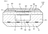
- FIG. 1 is a cross-sectional view of the gas sensor of Embodiment 1 having the gas sensor element of Embodiment 1
- FIG. 2 is a cross-sectional view of the gas sensor element of Embodiment 1 included in the gas sensor of Embodiment 1, cut in a direction orthogonal to the longitudinal direction thereof
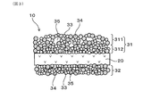
- FIG. 3 is an explanatory view schematically showing a fine structure of a measurement electrode and a reference electrode which the gas sensor element of Embodiment 1 has
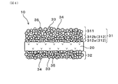
- FIG. 4 is an explanatory view schematically showing a fine structure of a measurement electrode and a reference electrode which the gas sensor element of Embodiment 2 has
- FIG. 1 is a cross-sectional view of the gas sensor of Embodiment 1 having the gas sensor element of Embodiment 1
- FIG. 2 is a cross-sectional view of the gas sensor element of Embodiment 1 included in the gas sensor of Embodiment 1, cut in a direction orthogonal to the longitudinal direction thereof
- FIG. 3 is an explanatory view schematic
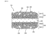
- FIG. 5 is an explanatory view schematically showing a fine structure of a measurement electrode and a reference electrode which the gas sensor element of Embodiment 3 has
- FIG. 6 is a backscattered electron image by a scanning electron microscope showing the microstructure of the measurement electrode in the gas sensor element of Sample 1 in Experimental Example 1
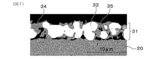
- FIG. 7 is a backscattered electron image by a scanning electron microscope showing the microstructure of the measurement electrode in the gas sensor element of Sample 1C in Experimental Example 1
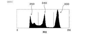
- FIG. 8 is an example in which the backscattered electron image of the measurement electrode in Experimental Example 1 is divided into each of the noble metal particle region, the solid electrolyte particle region, and the pore region in the luminance distribution
- FIG. 6 is a backscattered electron image by a scanning electron microscope showing the microstructure of the measurement electrode in the gas sensor element of Sample 1 in Experimental Example 1
- FIG. 7 is a backscattered electron image by a scanning electron microscope showing the microstructure of the measurement electrode in the gas sensor element of Sample 1C in Experimental Example
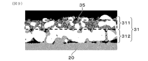
- FIG. 9 is an example of an image of a pore region when calculating the porosity of the surface measurement electrode layer in Experimental Example 1;
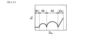
- FIG. 10 is a schematic explanatory view of a Cole-Cole plot when determining electrode reaction resistance in Experimental Example 1;
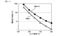
- FIG. 11 is a graph showing the relationship between sensor temperature (° C.) and electrode reaction resistance ( ⁇ ) in Experimental Example 1
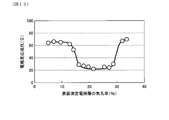
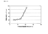
- FIG. 12 is a graph showing the relationship between the porosity (%) of the surface measurement electrode layer and the electrode reaction resistance ( ⁇ ) in Experimental Example 2
- FIG. 13 is a graph showing the relationship between the porosity (%) of the intermediate measurement electrode layer and the electrode specific resistance ( ⁇ ) in Experimental Example 3
- FIG. 10 is a schematic explanatory view of a Cole-Cole plot when determining electrode reaction resistance in Experimental Example 1
- FIG. 11 is a graph showing the relationship between sensor temperature (° C.) and electrode reaction resistance ( ⁇ ) in Experimental Example 1
- FIG. 12 is a graph showing the relationship between the porosity (%) of the surface
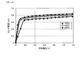
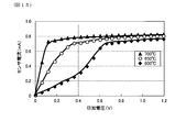
- FIG. 14 is a graph showing the relationship between the applied voltage (V) and the sensor current (mA) of the gas sensor of Sample 1 in Experimental Example 4
- FIG. 15 is a graph showing the relationship between the applied voltage (V) and the sensor current (mA) of the gas sensor of Sample 1C in Experimental Example 4.
- the gas sensor element 10 of the present embodiment includes a solid electrolyte body 20 having oxygen ion conductivity and a measurement electrode provided on one surface of the solid electrolyte body 20 and exposed to a measurement gas G. 31 and a reference electrode 32 provided on the other surface of the solid electrolyte body 20 and exposed to the reference gas A.
- Each of the measurement electrode 31 and the reference electrode 32 is configured to include noble metal particles 33, solid electrolyte particles 34 having oxygen ion conductivity, and pores 35.
- the gas sensor 1 of the present embodiment has the gas sensor element 10 of the present embodiment. The details will be described below.
- the gas sensor 1 uses the exhaust gas exhausted from the internal combustion engine as the measurement gas G, and uses the atmosphere as the reference gas A to measure the oxygen concentration in the measurement gas G, the concentration of specific gas components, etc.
- Exhaust system sensor Specifically, in the present embodiment, the gas sensor 1 is disposed in an exhaust pipe of an engine as an internal combustion engine, and the exhaust gas passing through the exhaust pipe is a measurement gas G, and the atmosphere is a reference gas A.
- the A / F sensor is an A / F sensor that obtains an A / F (air-fuel ratio) in the engine based on the oxygen concentration.
- the gas sensor 1 can be an A / F sensor that quantitatively determines the air-fuel ratio of the engine by utilizing the limiting current characteristic based on the diffusion rate limit of the measurement gas G.
- the gas sensor 1 is a concentration cell type that detects whether the air-fuel ratio, which is the mixture ratio of fuel and air in the engine, is in a fuel-rich or an air-rich lean state with respect to the theoretical air-fuel ratio. It can also be The gas sensor 1 can also be configured as a gas sensor other than the A / F sensor. That is, if it is a gas sensor provided with a gas sensor element having an electrode including noble metal particles, solid electrolyte particles having oxygen ion conductivity, and pores, the gas sensor element 10 of this embodiment can be applied.
- the gas sensor 1 includes the gas sensor element 10, the insulator 62 holding the gas sensor element 10, the housing 61 holding the insulator 62, the inner cover 7 held by the housing 61, and An outer cover 8 is provided.
- the gas sensor element 10 has a protrusion 11 that protrudes from the insulator 62.
- the inner cover 7 and the outer cover 8 cover the protrusion 11 of the gas sensor element 10.
- the projecting portion 11 is provided with a gas measuring unit 12 in which the measurement gas G is taken and the oxygen concentration in the measurement gas G is measured.
- the inner cover 7 is formed with inner passage holes 711 and 721 through which the measurement gas G passes
- the outer cover 8 is formed with outer passage holes 811 and 821 through which the measurement gas G passes.
- the arrangement of the inner passage holes 711, 721 and the outer passage holes 811, 821 is not particularly limited.
- the gas measurement unit 12 includes an introduction unit 13 into which the measurement gas G is introduced, a measurement electrode 31 provided on one surface of the solid electrolyte body 20 and exposed to the measurement gas G, and a solid electrolyte A reference electrode 32 provided on the other surface of the body 20 and exposed to the reference gas A, and a part of the solid electrolyte body 20 sandwiched between the measurement electrode 31 and the reference electrode 32 are provided.
- a heater 5 for heating and activating the solid electrolyte body 20, the measurement electrode 31 and the reference electrode 32 is stacked on the solid electrolyte body 20 in the gas sensor element 10.
- a measurement gas chamber 41 into which a measurement gas G is introduced is formed on one surface of the solid electrolyte body 20, and the measurement electrode 31 is disposed in the measurement gas chamber 41.
- the measurement gas chamber 41 is formed so as to be surrounded by the insulator 43 and the diffusion resistance layer 44 which allows the measurement gas G to pass at a predetermined diffusion rate.
- a reference gas chamber 42 into which a reference gas A is introduced is formed on the other surface of the solid electrolyte body 20, and the reference electrode 32 is disposed in the reference gas chamber 42.
- the heater 5 stacked on the solid electrolyte body 20 is formed of a heating element 52 that generates heat by energization and a ceramic substrate 51 in which the heating element 52 is embedded.
- the reference gas chamber 42 is formed so as to be surrounded by the ceramic substrate 51.
- the solid electrolyte body 20 has a plate shape, and is made of a solid electrolyte such as a stabilized zirconia or a partially stabilized zirconia containing a rare earth metal element or an alkaline earth metal element.
- the solid electrolyte body 20 can be specifically made of yttria partially stabilized zirconia.
- each of the measurement electrode 31 and the reference electrode 32 is configured to include noble metal particles 33, solid electrolyte particles 34, and pores 35.
- the noble metal constituting the noble metal particles 33 examples include Pt, Pd, Rh, Ir, Ru, Os, Au, Ag, alloys thereof, and the like.
- the noble metal constituting the noble metal particles 33 may preferably be Pt or an alloy of Pt and at least one selected from the group consisting of Rh, Pd, Au, and Ag. According to this configuration, since the catalytic activity of the electrode is excellent, it is advantageous for improving the electrode reaction resistance at the time of low temperature operation.
- a solid electrolyte which comprises the solid electrolyte particle 34 the solid electrolyte etc. which were mentioned above can be illustrated.
- the noble metal particles 33 can be Pt particles or Pt alloy particles
- the solid electrolyte particles 34 can be zirconia-based solid electrolyte particles such as yttria-stabilized zirconia particles.
- the intersection point between the surface of the noble metal particle 33 and the surface of the solid electrolyte particle 34 and the pores 35 (gas in the pores 35) is due to the noble metal particles 33, the solid electrolyte particles 34 and the pores 35 (gas in the pores 35).
- Three-phase point (not shown).
- the mass ratio of the noble metal particles 33 to the solid electrolyte particles 34 can be, for example, in the range of 90:10 to 60:40.
- the measurement electrode 31 is disposed in contact with the surface measurement electrode layer 311 provided with the surface to be the contact surface with the measurement gas G and the surface of the surface measurement electrode layer 311 on the solid electrolyte body 20 side. And an intermediate measurement electrode layer 312.
- the detailed laminated structure of the measurement electrode 31 is omitted in FIGS. 1 and 2.
- the intermediate measurement electrode layer 312 is configured of one layer (single layer).
- the porosity of the surface measurement electrode layer 311 is larger than the porosity of the intermediate measurement electrode layer 312.
- the magnitude relationship between the respective porosity can be grasped by observing a cross section perpendicular to the electrode surface with a scanning electron microscope (SEM).
- a backscattered electron image of a cross section perpendicular to the surface of the measurement electrode 31 is obtained by the SEM.
- the obtained backscattered electron image is divided into noble metal particle regions, solid electrolyte particle regions, and pore regions according to the brightness distribution using image analysis software (Mitani Corporation, "WinROOF").
- image analysis software Mitsubishi Corporation, "WinROOF”
- the image of the area the area of the entire analysis area in the surface measurement electrode layer 311 and the total area of the pores 35 in the analysis area in the surface measurement electrode layer 311 are determined.
- the porosity (%) of the surface measurement electrode layer 311 is calculated by the formula of the total area of the pores 35 / [the area of the entire analysis region in the surface measurement electrode layer 311]
- the intermediate measurement is performed on the image of the pore region.
- the area of the entire analysis area in the electrode layer 312 and the total area of the pores 35 in the analysis area in the intermediate measurement electrode layer 312 are determined.
- the porosity (%) of the intermediate measurement electrode layer 312 is calculated by the formula of the total area of the pores 35 in the analysis region in the electrode layer 312 / [the area of the entire analysis region in the intermediate measurement electrode layer 312].
- the magnitude relation between the porosity (%) of the surface measurement electrode layer 311 and the porosity (%) of the intermediate measurement electrode layer 312 can be grasped.
- the gas sensor element 10 can be obtained, for example, as follows. After applying a mixture for intermediate measurement electrode layer 312 including noble metal particles 33, solid electrolyte particles 34 and, if necessary, a pore forming agent on one surface of solid electrolyte body 20, noble metal particles 33 and solid electrolyte particles are further added. The mixture for the surface measuring electrode layer 311 is applied, including 34 and optionally a pore forming agent. At this time, in order to satisfy the relationship of the porosity of the intermediate measurement electrode layer 312 ⁇ the porosity of the surface measurement electrode layer 311, for example, the content of the pore forming agent contained in the mixture for the surface measurement electrode layer 311 The content of the pore forming agent contained in the mixture for the intermediate measurement electrode layer 312 may be increased.
- the mixing ratio of the noble metal particles 33 and the solid electrolyte particles 34 in the mixture for the surface measurement electrode layer 311 and the mixing ratio of the noble metal particles 33 and the solid electrolyte particles 34 in the mixture for the intermediate measurement electrode layer 312 It is also good. Then, on the other surface of the solid electrolyte body 20, a mixture for the reference electrode 32 including the noble metal particles 33, the solid electrolyte particles 34, and the pore forming agent as needed is applied. Then, it is fired. Thereby, the gas sensor element 10 can be obtained.
- the gas sensor element 10 of the present embodiment has the above configuration. Therefore, in the gas sensor element 10, the surface of the noble metal particle 33 and the surface of the solid electrolyte particle 34 at the intersection point of the pores 35 by the surface measurement electrode layer 311 having a large porosity provided with the surface to be a contact surface with the measurement gas G A certain three-phase point is increased, the reactivity of the measurement gas G is improved, and the electrode reaction resistance can be reduced.
- the electrode conductivity of the gas sensor element 10 can be secured by the intermediate measurement electrode layer 312 on the side of the solid electrolyte body 20 having a smaller porosity than the surface measurement electrode layer 311, and an increase in electrode specific resistance can be suppressed.
- the porosity of the surface measurement electrode layer 311 can be 15% or more and 30% or less. According to this configuration, the reactivity of the measurement gas G is improved by the increase of the contact opportunity with the measurement gas G, and the electrode reaction resistance is easily reduced. In addition, since the electron conduction path in the surface measurement electrode layer 311 is secured by an appropriate amount of pores, it is easy to suppress an increase in electrode specific resistance.
- the porosity of the surface measurement electrode layer 311 can be preferably 16% or more, more preferably 17% or more, and still more preferably 18% or more from the viewpoint of a decrease in electrode reaction resistance and the like. Further, the porosity of the surface measurement electrode layer 311 is preferably 29% or less, more preferably 28% or less, still more preferably 27%, from the viewpoint of improvement of electrode conductivity by suppression of increase in electrode specific resistance, etc. The following can be made.
- the porosity of the intermediate measurement electrode layer 312 can be 15% or less. According to this configuration, since the electron conduction path in the intermediate measurement electrode layer 312 is secured by an appropriate amount of pores, it is easy to suppress an increase in electrode specific resistance.
- the porosity of the intermediate measurement electrode layer 312 is preferably less than 15%, more preferably 14% or less, still more preferably 13% or less, and still more preferably, from the viewpoint of a decrease in electrode reaction resistance and the like. It can be 12% or less.
- the porosity of the intermediate measurement electrode layer 312 can be, for example, 3% or more from the viewpoint of stress relaxation due to thermal expansion of the solid electrolyte body 20 and the surface measurement electrode layer 311.
- the thickness of the surface measurement electrode layer 311 and the intermediate measurement electrode layer 312 can be preferably 1 to 10 ⁇ m from the viewpoint of ease of formation by a printing method such as screen printing.
- the thickness of the reference electrode 32 can be preferably 2 to 20 ⁇ m from the viewpoint of ease of formation by a printing method such as screen printing.
- the gas sensor 1 of the present embodiment has the gas sensor element 10 of the present embodiment described above. Therefore, the gas sensor 1 has high electrode activity at low temperatures, which is advantageous for low temperature operation of the sensors. Specifically, the gas sensor 1 can be used, for example, in a temperature range of 550 to 800.degree.
- the intermediate measurement electrode layer 312 is configured of a plurality of layers.
- the porosity of each of the layers constituting the intermediate measurement electrode layer 312 it is possible to control the porosity of each of the layers constituting the intermediate measurement electrode layer 312, so that it is possible to obtain the gas sensor element 10 that can easily obtain the above-described effects.
- the porosity of each layer can be controlled, for example, by adjusting the mixing ratio of the noble metal particles 33 and the solid electrolyte particles 34 contained in each layer.
- FIG. 4 shows an example in which the intermediate measurement electrode layer 312 is composed of at least two layers of an inner layer 312a and an outer layer 312b.
- the intermediate measurement electrode layer 312 can also be composed of three or more layers without being limited to FIG.
- the layers constituting the intermediate measurement electrode layer 312 can increase the porosity as they are closer to the surface measurement electrode layer 311 and can decrease the porosity as they are closer to the solid electrolyte body 20. More specifically, the porosity of each layer constituting the intermediate measurement electrode layer 312 can be configured to increase from the solid electrolyte body 20 side toward the surface measurement electrode layer 311. However, the porosity of each layer constituting the intermediate measurement electrode layer 312 is smaller than the porosity of the surface measurement electrode layer 311. Specifically, the porosity of each layer constituting the intermediate measurement electrode layer 312 can be 15% or less. The other configurations and effects are the same as in the first embodiment.
- the gas sensor 1 of the present embodiment has the gas sensor element 10 of the present embodiment described above.
- the other configurations and effects are the same as in the first embodiment.
- Embodiment 3 The gas sensor element and the gas sensor of Embodiment 3 will be described with reference to FIG.
- the surface reference electrode layer 321 having the surface where the reference electrode 32 is a contact surface with the reference gas A, and the solid electrolyte of the surface reference electrode layer 321 And an intermediate reference electrode layer 322 disposed in contact with the surface on the body 20 side.
- the porosity of the surface reference electrode layer 321 is larger than the porosity of the intermediate reference electrode layer 322.
- the gas sensor element 10 of the present embodiment has the above configuration. Therefore, in the gas sensor element 10, the surface reference electrode layer 321 having a large porosity provided with the surface to be the contact surface with the reference gas A, the intersection point of the surface of the noble metal particles 33 and the surface of the solid electrolyte particles 34 and the pores 35. A certain three-phase point is increased, the reactivity of the reference gas A is improved, and the electrode reaction resistance can be reduced. Further, in the gas sensor element 10, the intermediate reference electrode layer 322 on the side of the solid electrolyte body 20 having a smaller porosity than the surface reference electrode layer 321 can ensure the electrode conductivity and can suppress an increase in electrode specific resistance.
- the effects of the measurement electrode 31 and the reference electrode 32 can be combined to further reduce the electrode reaction resistance and to more effectively suppress the increase in the electrode specific resistance. it can.
- the other configurations and operational effects are the same as in the first embodiment.
- the “surface measurement electrode layer 311” in Embodiment 1 can be read as “the surface reference electrode layer 321” and applied.
- the “intermediate measurement electrode layer 312” in Embodiment 1 can be read as “the intermediate reference electrode layer 322” and applied.
- the gas sensor 1 of the present embodiment has the gas sensor element 10 of the present embodiment described above.
- the other configurations and effects are the same as in the first embodiment.
- An intermediate measurement electrode layer forming paste containing noble metal particles, solid electrolyte particles, and a pore forming agent is screen-printed to a thickness of 7 ⁇ m on one surface of the solid electrolyte body, and then noble metal particles, solid electrolyte particles, and a pore forming agent
- the surface measurement electrode layer forming paste including the above was screen printed with a thickness of 7 .mu.m.
- the mass ratio of the noble metal particles to the solid electrolyte particles in the intermediate measurement electrode layer forming paste is 97: 3.
- the mass ratio of the noble metal particles to the solid electrolyte particles in the surface measurement electrode layer forming paste is 96: 4.
- a paste for forming a reference electrode containing noble metal particles, solid electrolyte particles and a pore forming agent was screen-printed to a thickness of 7 ⁇ m.
- the mass ratio of the noble metal particles to the solid electrolyte particles in the reference electrode-forming paste is 97: 3.
- yttria partially stabilized zirconia was used for the solid electrolyte body.
- Pt particles primary particle diameter: 0.6 to 10 ⁇ m
- Yttria-stabilized zirconia primary particle diameter: 0.2 to 3 ⁇ m
- the solid electrolyte body on which each paste was printed was fired at 1450 ° C.
- the gas sensor element of Sample 1 was obtained.
- the intermediate measurement electrode layer forming paste was only screen-printed to a thickness of 14 ⁇ m on one surface of the solid electrolyte body, and thereafter the surface measurement electrode layer forming paste was not screen-printed
- a gas sensor of sample 1C was obtained in the same manner except for the point.
- the measurement electrode of the gas sensor element of each sample was observed by SEM.
- the results are shown in FIG. 6 and FIG. According to FIG. 7, it can be seen that in the gas sensor element of sample 1C, the measurement electrode is constituted by a single layer.
- the measurement electrode includes noble metal particles, solid electrolyte particles having oxygen ion conductivity, and pores, and the measurement It can be seen that the electrode has a surface measurement electrode layer having a surface to be a contact surface with the measurement gas, and an intermediate measurement electrode layer disposed in contact with the surface of the surface measurement electrode layer on the solid electrolyte body side.
- the porosity of the surface measurement electrode layer measured by the above-described measurement method is 22%
- the porosity of the intermediate measurement electrode layer is 8%
- the porosity of the surface measurement electrode layer is higher than the porosity of the intermediate measurement electrode layer It was big too.
- FIG. 8 shows an example in which the reflection electron image of the measurement electrode 31 is divided into the noble metal particle region 330, the solid electrolyte particle region 340, and the pore region 350 in the luminance distribution.
- FIG. 9 shows an example of an image of the pore region when calculating the porosity of the surface measurement electrode layer.
- the electrode reaction resistance of the measurement electrode was measured for the gas sensor element of each sample. Specifically, the intergranular resistance of the solid electrolyte particles, the intergranular resistance of the solid electrolyte particles, and the electrode reaction resistance of the measurement electrode are measured at 550 to 800 ° C. by impedance measurement at a frequency of 1 MHz to 0.1 Hz. The electrode reaction resistance was analyzed by Cole-Cole plot as shown in FIG. In FIG. 9, R1 is the intragranular resistance of the solid electrolyte particles. R2 is the grain boundary resistance of solid electrolyte particles. R3 is an electrode reaction resistance. Zw is a gas diffusion resistance. Z Re is a real component of impedance. Z Im is an imaginary component of impedance.
- FIG. 11 shows the relationship between the sensor temperature (° C.) and the electrode reaction resistance ( ⁇ ). As shown in FIG. 11, it can be seen that the gas sensor element of sample 1 has lower electrode reaction resistance in the entire sensor temperature range as compared to the gas sensor element of sample 1C.
- the electrode specific resistance of the measurement electrode in the gas sensor element of sample 1 was 21 ( ⁇ ⁇ cm), and the electrode specific resistance of the measurement electrode in the gas sensor element of sample 1C was 20 ( ⁇ ⁇ cm). From this result, it can be seen that the gas sensor element of sample 1 can suppress an increase in electrode specific resistance as compared to the gas sensor element of sample 1C.
- Example 2 A plurality of gas sensor elements different in the porosity of the surface measurement electrode layer were manufactured according to the production of the gas sensor element of the sample 1, and the relationship between the porosity of the surface measurement electrode layer and the electrode reaction resistance was determined. The results are shown in FIG.
- Example 3 A plurality of gas sensor elements different in the porosity of the intermediate measurement electrode layer were manufactured according to the production of the gas sensor element of the sample 1, and the relationship between the porosity of the intermediate measurement electrode layer and the electrode specific resistance was determined. The results are shown in FIG.
- Example 4 The relationship between the voltage applied to the gas sensor and the sensor current was measured when the temperature was set to 600 ° C., 650 ° C., and 700 ° C. in the atmosphere using the gas sensor of sample 1 incorporating the gas sensor element of sample 1. The results are shown in FIG. Further, using the gas sensor of sample 1C incorporating the gas sensor element of sample 1C, the relationship between the voltage applied to the gas sensor and the sensor current was measured when the temperature was set to 600 ° C., 650 ° C., and 700 ° C. in the atmosphere. The results are shown in FIG. In the present experimental example, the gas sensor is used as an A / F (air-fuel ratio) sensor, and is configured to obtain an air-fuel ratio by measuring a current value of 0.4 V.
- a / F air-fuel ratio
- the gas sensor of Sample 1C can not obtain stable output at low temperatures of 600 ° C. and 650 ° C.
- FIG. 14 it can be seen that the gas sensor of Sample 1 can obtain stable output in all temperature ranges of 600 ° C., 650 ° C. and 700 ° C. From this result, it can be said that the gas sensor of the sample 1 has high electrode activity at low temperatures, is advantageous for low temperature operation of the sensors, and can save energy by reducing the amount of heater used.
- the present disclosure is not limited to the above embodiments and experimental examples, and various modifications can be made without departing from the scope of the invention. That is, although the present disclosure has been described based on the embodiments, it is understood that the present disclosure is not limited to the embodiments, structures, and the like. The present disclosure includes various modifications and variations within the equivalent range. In addition, various combinations and forms, and further, other combinations and forms including only one element, or more or less than these elements are also within the scope and the scope of the present disclosure. Moreover, each structure shown by each embodiment and each experiment example can each be combined arbitrarily. For example, the configuration of the reference electrode in the first embodiment can be replaced with the configuration of the reference electrode in the third embodiment. The configuration of the reference electrode in the second embodiment can be replaced with the configuration of the reference electrode in the third embodiment. Further, in each of the above-described modifications, the intermediate reference electrode layer constituting each reference electrode can be constituted of a plurality of layers.
Landscapes
- Chemical & Material Sciences (AREA)
- Life Sciences & Earth Sciences (AREA)
- Health & Medical Sciences (AREA)
- Physics & Mathematics (AREA)
- Chemical Kinetics & Catalysis (AREA)
- Electrochemistry (AREA)
- Molecular Biology (AREA)
- Analytical Chemistry (AREA)
- Biochemistry (AREA)
- General Health & Medical Sciences (AREA)
- General Physics & Mathematics (AREA)
- Immunology (AREA)
- Pathology (AREA)
- Measuring Oxygen Concentration In Cells (AREA)
Priority Applications (2)
| Application Number | Priority Date | Filing Date | Title |
|---|---|---|---|
| DE112018005171.4T DE112018005171T5 (de) | 2017-09-15 | 2018-09-05 | Gassensorelement und gassensor |
| US16/813,995 US12111283B2 (en) | 2017-09-15 | 2020-03-10 | Gas sensor element and gas sensor |
Applications Claiming Priority (2)
| Application Number | Priority Date | Filing Date | Title |
|---|---|---|---|
| JP2017178178A JP6752184B2 (ja) | 2017-09-15 | 2017-09-15 | ガスセンサ素子およびガスセンサ |
| JP2017-178178 | 2017-09-15 |
Related Child Applications (1)
| Application Number | Title | Priority Date | Filing Date |
|---|---|---|---|
| US16/813,995 Continuation US12111283B2 (en) | 2017-09-15 | 2020-03-10 | Gas sensor element and gas sensor |
Publications (1)
| Publication Number | Publication Date |
|---|---|
| WO2019054255A1 true WO2019054255A1 (ja) | 2019-03-21 |
Family
ID=65723615
Family Applications (1)
| Application Number | Title | Priority Date | Filing Date |
|---|---|---|---|
| PCT/JP2018/032909 Ceased WO2019054255A1 (ja) | 2017-09-15 | 2018-09-05 | ガスセンサ素子およびガスセンサ |
Country Status (4)
| Country | Link |
|---|---|
| US (1) | US12111283B2 (enExample) |
| JP (1) | JP6752184B2 (enExample) |
| DE (1) | DE112018005171T5 (enExample) |
| WO (1) | WO2019054255A1 (enExample) |
Families Citing this family (7)
| Publication number | Priority date | Publication date | Assignee | Title |
|---|---|---|---|---|
| US11328906B2 (en) * | 2018-07-30 | 2022-05-10 | Toto Ltd. | Electrostatic chuck |
| JP7538822B2 (ja) | 2021-01-22 | 2024-08-22 | 日本碍子株式会社 | NOxセンサのセンサ素子 |
| US12222314B2 (en) * | 2021-01-22 | 2025-02-11 | Ngk Insulators, Ltd. | Sensor element of NOx sensor |
| US12222313B2 (en) * | 2021-01-22 | 2025-02-11 | Ngk Insulators, Ltd. | Sensor element of gas sensor |
| JP7588103B2 (ja) | 2021-01-22 | 2024-11-21 | 日本碍子株式会社 | NOxセンサのセンサ素子およびNOxセンサのセンサ素子の製造方法 |
| DE102022000154A1 (de) | 2021-01-22 | 2022-07-28 | Ngk Insulators, Ltd. | SENSORELEMENT EINES NOx-SENSORS UND VERFAHREN ZUR HERSTELLUNG EINES SENSORELEMENTS EINES NOx-SENSORS |
| JP7538821B2 (ja) | 2021-01-22 | 2024-08-22 | 日本碍子株式会社 | ガスセンサのセンサ素子 |
Citations (5)
| Publication number | Priority date | Publication date | Assignee | Title |
|---|---|---|---|---|
| JP2002005878A (ja) * | 2000-04-22 | 2002-01-09 | Robert Bosch Gmbh | 電気化学的測定センサー |
| JP2004061323A (ja) * | 2002-07-29 | 2004-02-26 | Kyocera Corp | 酸素センサ素子 |
| JP2017020838A (ja) * | 2015-07-08 | 2017-01-26 | 株式会社日本自動車部品総合研究所 | ガスセンサのポンプ電極及び基準電極 |
| JP2017090405A (ja) * | 2015-11-17 | 2017-05-25 | 日本碍子株式会社 | ガスセンサの検知電極、ガスセンサ、および、ガスセンサの製造方法 |
| JP2017518506A (ja) * | 2014-06-18 | 2017-07-06 | ローベルト ボツシユ ゲゼルシヤフト ミツト ベシユレンクテル ハフツングRobert Bosch Gmbh | 測定ガス空間内の測定ガスの少なくとも1つの特性を検知するためのセンサ素子 |
Family Cites Families (7)
| Publication number | Priority date | Publication date | Assignee | Title |
|---|---|---|---|---|
| JPH0668480B2 (ja) * | 1987-04-24 | 1994-08-31 | 日本碍子株式会社 | 酸素センサにおける電極構造 |
| US5593558A (en) * | 1994-06-09 | 1997-01-14 | Nippondenso Co., Ltd. | Oxygen concentration detector |
| DE19833087A1 (de) * | 1998-07-23 | 2000-01-27 | Bosch Gmbh Robert | Gassensor und Verfahren zu dessen Herstellung |
| JP2007121173A (ja) | 2005-10-31 | 2007-05-17 | Denso Corp | ガスセンサ素子及びその製造方法 |
| JP4409581B2 (ja) | 2007-02-05 | 2010-02-03 | 京セラ株式会社 | 酸素センサ素子 |
| JP6131166B2 (ja) | 2012-11-22 | 2017-05-17 | 株式会社デンソー | ガスセンサ用の電極及びそれを用いたガスセンサ素子 |
| JP6282302B2 (ja) | 2016-03-31 | 2018-02-21 | 本田技研工業株式会社 | 車体構造および車両の製造方法 |
-
2017
- 2017-09-15 JP JP2017178178A patent/JP6752184B2/ja active Active
-
2018
- 2018-09-05 DE DE112018005171.4T patent/DE112018005171T5/de active Pending
- 2018-09-05 WO PCT/JP2018/032909 patent/WO2019054255A1/ja not_active Ceased
-
2020
- 2020-03-10 US US16/813,995 patent/US12111283B2/en active Active
Patent Citations (5)
| Publication number | Priority date | Publication date | Assignee | Title |
|---|---|---|---|---|
| JP2002005878A (ja) * | 2000-04-22 | 2002-01-09 | Robert Bosch Gmbh | 電気化学的測定センサー |
| JP2004061323A (ja) * | 2002-07-29 | 2004-02-26 | Kyocera Corp | 酸素センサ素子 |
| JP2017518506A (ja) * | 2014-06-18 | 2017-07-06 | ローベルト ボツシユ ゲゼルシヤフト ミツト ベシユレンクテル ハフツングRobert Bosch Gmbh | 測定ガス空間内の測定ガスの少なくとも1つの特性を検知するためのセンサ素子 |
| JP2017020838A (ja) * | 2015-07-08 | 2017-01-26 | 株式会社日本自動車部品総合研究所 | ガスセンサのポンプ電極及び基準電極 |
| JP2017090405A (ja) * | 2015-11-17 | 2017-05-25 | 日本碍子株式会社 | ガスセンサの検知電極、ガスセンサ、および、ガスセンサの製造方法 |
Also Published As
| Publication number | Publication date |
|---|---|
| DE112018005171T5 (de) | 2020-06-10 |
| US12111283B2 (en) | 2024-10-08 |
| JP6752184B2 (ja) | 2020-09-09 |
| US20200209184A1 (en) | 2020-07-02 |
| JP2019052973A (ja) | 2019-04-04 |
Similar Documents
| Publication | Publication Date | Title |
|---|---|---|
| JP6752184B2 (ja) | ガスセンサ素子およびガスセンサ | |
| CN103998922B (zh) | 气体传感器用电极及气体传感器 | |
| JP6382162B2 (ja) | ガスセンサのポンプ電極及び基準電極 | |
| JP6678134B2 (ja) | ガスセンサ素子およびガスセンサ | |
| JP5638984B2 (ja) | ガスセンサ | |
| US12181436B2 (en) | Gas sensor element and gas sensor | |
| KR102687801B1 (ko) | 측정 가스 챔버 내의 측정 가스의 적어도 하나의 특성을 검출하기 위한 센서 소자 | |
| JP2021124382A (ja) | ガスセンサ | |
| JP5278499B2 (ja) | ガスセンサ素子及びそれを用いたガスセンサ | |
| JP6540661B2 (ja) | ガスセンサ素子及びガスセンサ | |
| US11209387B2 (en) | Gas sensor element and gas sensor | |
| US11656196B2 (en) | Solid electrolyte, manufacturing method thereof, and gas sensor | |
| CN111492235B (zh) | 传感器元件和气体传感器 | |
| JP2017510813A (ja) | 測定ガス空間における測定ガスの少なくとも1つの特性を検出するためのセンサ素子および該センサ素子を製造する方法 | |
| JP2019085286A (ja) | 固体電解質、その製造方法、ガスセンサ | |
| JP2017223495A (ja) | ガスセンサ素子およびガスセンサ | |
| JP5724832B2 (ja) | 酸素濃度センサ | |
| JP2014052327A (ja) | ガスセンサ素子およびガスセンサ | |
| JPH04291143A (ja) | 酸素センサ及びその製造方法 | |
| JP2013015502A (ja) | ガス選択性酸素センサ素子 |
Legal Events
| Date | Code | Title | Description |
|---|---|---|---|
| 121 | Ep: the epo has been informed by wipo that ep was designated in this application |
Ref document number: 18855790 Country of ref document: EP Kind code of ref document: A1 |
|
| 122 | Ep: pct application non-entry in european phase |
Ref document number: 18855790 Country of ref document: EP Kind code of ref document: A1 |