WO2019054255A1 - Gas sensor element and gas sensor - Google Patents
Gas sensor element and gas sensor Download PDFInfo
- Publication number
- WO2019054255A1 WO2019054255A1 PCT/JP2018/032909 JP2018032909W WO2019054255A1 WO 2019054255 A1 WO2019054255 A1 WO 2019054255A1 JP 2018032909 W JP2018032909 W JP 2018032909W WO 2019054255 A1 WO2019054255 A1 WO 2019054255A1
- Authority
- WO
- WIPO (PCT)
- Prior art keywords
- gas sensor
- electrode layer
- measurement electrode
- solid electrolyte
- sensor element
- Prior art date
Links
Images


Classifications
-
- G—PHYSICS
- G01—MEASURING; TESTING
- G01N—INVESTIGATING OR ANALYSING MATERIALS BY DETERMINING THEIR CHEMICAL OR PHYSICAL PROPERTIES
- G01N27/00—Investigating or analysing materials by the use of electric, electrochemical, or magnetic means
- G01N27/26—Investigating or analysing materials by the use of electric, electrochemical, or magnetic means by investigating electrochemical variables; by using electrolysis or electrophoresis
- G01N27/403—Cells and electrode assemblies
- G01N27/406—Cells and probes with solid electrolytes
- G01N27/407—Cells and probes with solid electrolytes for investigating or analysing gases
- G01N27/409—Oxygen concentration cells
-
- G—PHYSICS
- G01—MEASURING; TESTING
- G01N—INVESTIGATING OR ANALYSING MATERIALS BY DETERMINING THEIR CHEMICAL OR PHYSICAL PROPERTIES
- G01N27/00—Investigating or analysing materials by the use of electric, electrochemical, or magnetic means
- G01N27/26—Investigating or analysing materials by the use of electric, electrochemical, or magnetic means by investigating electrochemical variables; by using electrolysis or electrophoresis
- G01N27/403—Cells and electrode assemblies
- G01N27/406—Cells and probes with solid electrolytes
- G01N27/407—Cells and probes with solid electrolytes for investigating or analysing gases
- G01N27/4075—Composition or fabrication of the electrodes and coatings thereon, e.g. catalysts
-
- G—PHYSICS
- G01—MEASURING; TESTING
- G01N—INVESTIGATING OR ANALYSING MATERIALS BY DETERMINING THEIR CHEMICAL OR PHYSICAL PROPERTIES
- G01N27/00—Investigating or analysing materials by the use of electric, electrochemical, or magnetic means
- G01N27/26—Investigating or analysing materials by the use of electric, electrochemical, or magnetic means by investigating electrochemical variables; by using electrolysis or electrophoresis
- G01N27/403—Cells and electrode assemblies
- G01N27/406—Cells and probes with solid electrolytes
- G01N27/407—Cells and probes with solid electrolytes for investigating or analysing gases
- G01N27/4071—Cells and probes with solid electrolytes for investigating or analysing gases using sensor elements of laminated structure
-
- G—PHYSICS
- G01—MEASURING; TESTING
- G01N—INVESTIGATING OR ANALYSING MATERIALS BY DETERMINING THEIR CHEMICAL OR PHYSICAL PROPERTIES
- G01N27/00—Investigating or analysing materials by the use of electric, electrochemical, or magnetic means
- G01N27/26—Investigating or analysing materials by the use of electric, electrochemical, or magnetic means by investigating electrochemical variables; by using electrolysis or electrophoresis
- G01N27/403—Cells and electrode assemblies
- G01N27/406—Cells and probes with solid electrolytes
- G01N27/407—Cells and probes with solid electrolytes for investigating or analysing gases
- G01N27/4073—Composition or fabrication of the solid electrolyte
-
- G—PHYSICS
- G01—MEASURING; TESTING
- G01N—INVESTIGATING OR ANALYSING MATERIALS BY DETERMINING THEIR CHEMICAL OR PHYSICAL PROPERTIES
- G01N27/00—Investigating or analysing materials by the use of electric, electrochemical, or magnetic means
- G01N27/26—Investigating or analysing materials by the use of electric, electrochemical, or magnetic means by investigating electrochemical variables; by using electrolysis or electrophoresis
- G01N27/403—Cells and electrode assemblies
- G01N27/406—Cells and probes with solid electrolytes
- G01N27/407—Cells and probes with solid electrolytes for investigating or analysing gases
- G01N27/4075—Composition or fabrication of the electrodes and coatings thereon, e.g. catalysts
- G01N27/4076—Reference electrodes or reference mixtures
Abstract
This gas sensor element (10) comprises: a solid electrolyte body (20) which has oxygen ion conductivity; a measurement electrode (31) which is provided on one surface of the solid electrolyte body (20) and is exposed to a gas (G) to be measured; and a reference electrode (32) which is provided on the other surface of the solid electrolyte body (20) and is exposed to a reference gas (A). Both of the measurement electrode (31) and the reference electrode (32) are configured to contain noble metal particles (33), solid electrolyte particles (34) and pores (35). The measurement electrode (31) comprises: a surficial measurement electrode layer (311) which has a surface that serves as a contact surface to be in contact with the gas (G) to be measured; and an intermediate measurement electrode layer (312) which is arranged so as to be in contact with the solid electrolyte body (20)-side surface of the surficial measurement electrode layer (311). The porosity of the surficial measurement electrode layer (311) is higher than the porosity of the intermediate measurement electrode layer (312). A gas sensor (1) according to the present invention comprises this gas sensor element (10).
Description
本出願は、2017年9月15日に出願された日本出願番号2017-178178号に基づくもので、ここにその記載内容を援用する。
This application is based on Japanese Patent Application No. 2017-178178 filed on Sep. 15, 2017, the contents of which are incorporated herein by reference.
本開示は、ガスセンサ素子およびガスセンサに関する。
The present disclosure relates to a gas sensor element and a gas sensor.
従来、内燃機関の排気管に配置されるガスセンサとしては、例えば、酸素イオン伝導性を有する固体電解質体と、固体電解質体の一方面に設けられて測定ガスに曝される測定電極と、固体電解質体の他方面に設けられて基準ガスに曝される基準電極とを有するガスセンサ素子を有するガスセンサが知られている。ガスセンサ素子の電極は、一般に、Pt等の貴金属粒子と、酸素イオン伝導性を有する固体電解質粒子と、気孔とを含んで構成されている。
Conventionally, as a gas sensor disposed in an exhaust pipe of an internal combustion engine, for example, a solid electrolyte body having oxygen ion conductivity, a measurement electrode provided on one surface of the solid electrolyte body and exposed to a measurement gas, and a solid electrolyte There is known a gas sensor having a gas sensor element having a reference electrode provided on the other side of the body and exposed to a reference gas. Generally, the electrode of the gas sensor element is configured to include noble metal particles such as Pt, solid electrolyte particles having oxygen ion conductivity, and pores.
先行する特許文献1には、ガスセンサの応答性を向上させるため、測定電極が、金属粒子とセラミック粒子の配合比率の異なる少なくとも2層の電極層からなり、この測定電極における最も表面側の電極層におけるセラミック粒子の含有量が、最も固体電解質基板側の電極層よりも多い構成とされたガスセンサ素子が開示されている。
According to Patent Document 1 mentioned above, in order to improve the response of the gas sensor, the measurement electrode is composed of at least two electrode layers having different mixing ratios of metal particles and ceramic particles, and the electrode layer on the most surface side of this measurement electrode A gas sensor element is disclosed in which the content of ceramic particles in the above is greater than that of the electrode layer on the side of the solid electrolyte substrate.
しかしながら、従来のガスセンサ素子における測定電極は、最も表面側の電極層におけるセラミック粒子の含有量が多くされており、金属粒子が少ない。そのため、従来のガスセンサ素子は、金属粒子とセラミックス粒子と気孔(ガス)とによる三相点が少なくなり、電極反応抵抗が高くなる。また、上記測定電極において、気孔を増やすとガスとの反応性が向上して電極反応抵抗は低下するが、電極比抵抗が増加する。また、上記測定電極において、気孔を少なくすると電極比抵抗は低下するが、ガスとの反応性が低下して電極反応抵抗が増加する。
However, in the measurement electrode in the conventional gas sensor element, the content of ceramic particles in the electrode layer closest to the surface is increased, and the amount of metal particles is small. Therefore, in the conventional gas sensor element, the three-phase point due to the metal particles, the ceramic particles and the pores (gas) decreases, and the electrode reaction resistance becomes high. In the measurement electrode, when the number of pores is increased, the reactivity with the gas is improved and the electrode reaction resistance is decreased, but the electrode specific resistance is increased. In the measurement electrode, when the number of pores is reduced, the electrode specific resistance is decreased, but the reactivity with the gas is decreased and the electrode reaction resistance is increased.
本開示は、電極反応抵抗を低下させることができ、電極比抵抗の増加を抑制することができるガスセンサ素子、ガスセンサを提供することを目的とする。
An object of the present disclosure is to provide a gas sensor element and a gas sensor that can reduce electrode reaction resistance and can suppress an increase in electrode specific resistance.
本開示の一態様は、酸素イオン伝導性を有する固体電解質体と、上記固体電解質体の一方面に設けられて測定ガスに曝される測定電極と、上記固体電解質体の他方面に設けられて基準ガスに曝される基準電極とを有しており、
上記測定電極および上記基準電極は、いずれも、貴金属粒子と、酸素イオン伝導性を有する固体電解質粒子と、気孔とを含んで構成されており、
上記測定電極は、
上記測定ガスとの接触面となる表面を備える表面測定電極層と、上記表面測定電極層の上記固体電解質体側の面に接して配置された中間測定電極層と、を有しており、
上記表面測定電極層の気孔率は、上記中間測定電極層の気孔率よりも大きい、ガスセンサ素子にある。 One embodiment of the present disclosure includes a solid electrolyte body having oxygen ion conductivity, a measurement electrode provided on one side of the solid electrolyte body and exposed to a measurement gas, and provided on the other side of the solid electrolyte body And a reference electrode exposed to a reference gas,
Each of the measurement electrode and the reference electrode includes noble metal particles, solid electrolyte particles having oxygen ion conductivity, and pores.
The above measurement electrode is
A surface measurement electrode layer having a surface to be a contact surface with the measurement gas, and an intermediate measurement electrode layer disposed in contact with the surface of the surface measurement electrode layer on the solid electrolyte body side,
The porosity of the surface measurement electrode layer is larger than the porosity of the intermediate measurement electrode layer in the gas sensor element.
本開示の他の態様は、上記ガスセンサ素子を有するガスセンサにある。
Another aspect of the present disclosure is a gas sensor having the above gas sensor element.
上記ガスセンサ素子は、上記構成を有している。そのため、上記ガスセンサ素子は、測定ガスとの接触面となる表面を備える気孔率の大きな表面測定電極層により、貴金属粒子の表面と固体電解質粒子の表面と気孔との交わり点である三相点が増加し、測定ガスの反応性が向上して電極反応抵抗を低下させることができる。また、上記ガスセンサ素子は、表面測定電極層よりも気孔率の小さな固体電解質体側の中間測定電極層により、電極導電性が確保され、電極比抵抗の増加を抑制することができる。
The gas sensor element has the above configuration. Therefore, in the above gas sensor element, a surface measurement electrode layer having a large porosity is provided with a surface to be a contact surface with the measurement gas, and three phase points which are intersection points between the surface of noble metal particles and the surface of solid electrolyte particles Thus, the reactivity of the measurement gas can be improved and the electrode reaction resistance can be reduced. Further, in the gas sensor element, the intermediate measurement electrode layer on the solid electrolyte body side having a smaller porosity than the surface measurement electrode layer can ensure the electrode conductivity and can suppress an increase in electrode specific resistance.
上記ガスセンサは、上記ガスセンサ素子を有しているので、低温における電極活性が高く、センサの低温作動化に有利である。
Since the gas sensor has the gas sensor element, the electrode activity at a low temperature is high, which is advantageous for the low temperature operation of the sensor.
なお、請求の範囲に記載した括弧内の符号は、後述する実施形態に記載の具体的手段との対応関係を示すものであり、本開示の技術的範囲を限定するものではない。
In addition, the code in the parentheses described in the claims indicates the correspondence with the specific means described in the embodiments to be described later, and does not limit the technical scope of the present disclosure.
本開示についての上記目的およびその他の目的、特徴や利点は、添付の図面を参照しながら下記の詳細な記述により、より明確になる。その図面は、
図1は、実施形態1のガスセンサ素子を有する実施形態1のガスセンサの断面図であり、
図2は、実施形態1のガスセンサが有する実施形態1のガスセンサ素子を、その長手方向に直交する方向で切断したときの断面図であり、
図3は、実施形態1のガスセンサ素子が有する測定電極および基準電極の微構造を模式的に示した説明図であり、
図4は、実施形態2のガスセンサ素子が有する測定電極および基準電極の微構造を模式的に示した説明図であり、
図5は、実施形態3のガスセンサ素子が有する測定電極および基準電極の微構造を模式的に示した説明図であり、
図6は、実験例1における、試料1のガスセンサ素子における測定電極の微構造を示した走査型電子顕微鏡による反射電子像であり、
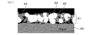
図7は、実験例1における、試料1Cのガスセンサ素子における測定電極の微構造を示した走査型電子顕微鏡による反射電子像であり、
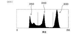
図8は、実験例1における、測定電極の反射電子像を、輝度分布にて、貴金属粒子領域、固体電解質粒子領域、気孔領域の各領域に分離した一例であり、
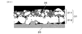
図9は、実験例1における、表面測定電極層の気孔率を算出する際における気孔領域の画像の一例であり、
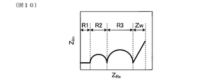
図10は、実験例1における、電極反応抵抗を求める際のCole-Coleプロットの模式的な説明図であり、
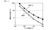
図11は、実験例1における、センサ温度(℃)と電極反応抵抗(Ω)との関係を示したグラフであり、
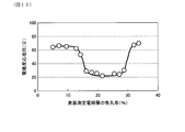
図12は、実験例2における、表面測定電極層の気孔率(%)と電極反応抵抗(Ω)との関係を示したグラフであり、
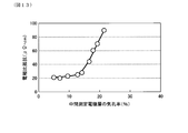
図13は、実験例3における、中間測定電極層の気孔率(%)と電極比抵抗(Ω)との関係を示したグラフであり、
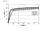
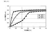
図14は、実験例4における、試料1のガスセンサの印加電圧(V)とセンサ電流(mA)との関係を示したグラフであり、
図15は、実験例4における、試料1Cのガスセンサの印加電圧(V)とセンサ電流(mA)との関係を示したグラフである。
The above object and other objects, features and advantages of the present disclosure will become more apparent from the following detailed description with reference to the attached drawings. The drawing is
FIG. 1 is a cross-sectional view of the gas sensor of Embodiment 1 having the gas sensor element of Embodiment 1, FIG. 2 is a cross-sectional view of the gas sensor element of Embodiment 1 included in the gas sensor of Embodiment 1, cut in a direction orthogonal to the longitudinal direction thereof, FIG. 3 is an explanatory view schematically showing a fine structure of a measurement electrode and a reference electrode which the gas sensor element of Embodiment 1 has, FIG. 4 is an explanatory view schematically showing a fine structure of a measurement electrode and a reference electrode which the gas sensor element of Embodiment 2 has, FIG. 5 is an explanatory view schematically showing a fine structure of a measurement electrode and a reference electrode which the gas sensor element of Embodiment 3 has, FIG. 6 is a backscattered electron image by a scanning electron microscope showing the microstructure of the measurement electrode in the gas sensor element of Sample 1 in Experimental Example 1; FIG. 7 is a backscattered electron image by a scanning electron microscope showing the microstructure of the measurement electrode in the gas sensor element of Sample 1C in Experimental Example 1; FIG. 8 is an example in which the backscattered electron image of the measurement electrode in Experimental Example 1 is divided into each of the noble metal particle region, the solid electrolyte particle region, and the pore region in the luminance distribution, FIG. 9 is an example of an image of a pore region when calculating the porosity of the surface measurement electrode layer in Experimental Example 1; FIG. 10 is a schematic explanatory view of a Cole-Cole plot when determining electrode reaction resistance in Experimental Example 1, FIG. 11 is a graph showing the relationship between sensor temperature (° C.) and electrode reaction resistance (Ω) in Experimental Example 1, FIG. 12 is a graph showing the relationship between the porosity (%) of the surface measurement electrode layer and the electrode reaction resistance (Ω) in Experimental Example 2, FIG. 13 is a graph showing the relationship between the porosity (%) of the intermediate measurement electrode layer and the electrode specific resistance (Ω) in Experimental Example 3, FIG. 14 is a graph showing the relationship between the applied voltage (V) and the sensor current (mA) of the gas sensor of Sample 1 in Experimental Example 4, FIG. 15 is a graph showing the relationship between the applied voltage (V) and the sensor current (mA) of the gas sensor of Sample 1C in Experimental Example 4.
(実施形態1)
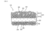
実施形態1のガスセンサ素子およびガスセンサについて、図1~図3を用いて説明する。図3に例示されるように、本実施形態のガスセンサ素子10は、酸素イオン伝導性を有する固体電解質体20と、固体電解質体20の一方面に設けられて測定ガスGに曝される測定電極31と、固体電解質体20の他方面に設けられて基準ガスAに曝される基準電極32とを有している。測定電極31および基準電極32は、いずれも、貴金属粒子33と、酸素イオン伝導性を有する固体電解質粒子34と、気孔35とを含んで構成されている。また、図1、図2に例示されるように、本実施形態のガスセンサ1は、本実施形態のガスセンサ素子10を有している。以下、詳説する。 (Embodiment 1)
The gas sensor element and the gas sensor ofEmbodiment 1 will be described with reference to FIGS. 1 to 3. As illustrated in FIG. 3, the gas sensor element 10 of the present embodiment includes a solid electrolyte body 20 having oxygen ion conductivity and a measurement electrode provided on one surface of the solid electrolyte body 20 and exposed to a measurement gas G. 31 and a reference electrode 32 provided on the other surface of the solid electrolyte body 20 and exposed to the reference gas A. Each of the measurement electrode 31 and the reference electrode 32 is configured to include noble metal particles 33, solid electrolyte particles 34 having oxygen ion conductivity, and pores 35. Moreover, as illustrated in FIG. 1 and FIG. 2, the gas sensor 1 of the present embodiment has the gas sensor element 10 of the present embodiment. The details will be described below.
実施形態1のガスセンサ素子およびガスセンサについて、図1~図3を用いて説明する。図3に例示されるように、本実施形態のガスセンサ素子10は、酸素イオン伝導性を有する固体電解質体20と、固体電解質体20の一方面に設けられて測定ガスGに曝される測定電極31と、固体電解質体20の他方面に設けられて基準ガスAに曝される基準電極32とを有している。測定電極31および基準電極32は、いずれも、貴金属粒子33と、酸素イオン伝導性を有する固体電解質粒子34と、気孔35とを含んで構成されている。また、図1、図2に例示されるように、本実施形態のガスセンサ1は、本実施形態のガスセンサ素子10を有している。以下、詳説する。 (Embodiment 1)
The gas sensor element and the gas sensor of
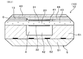
図1および図2に示されるように、ガスセンサ1は、内燃機関から排気される排ガスを測定ガスGとし、大気を基準ガスAとして、測定ガスG中の酸素濃度、特定ガス成分濃度等を測定する排気系センサである。本実施形態において、ガスセンサ1は、具体的には、内燃機関としてのエンジンの排気管に配置され、排気管を通過する排ガスを測定ガスGとするとともに、大気を基準ガスAとして、測定ガスGの酸素濃度を求め、この酸素濃度に基づいてエンジンにおけるA/F(空燃比)を求めるA/Fセンサである。ガスセンサ1は、より具体的には、測定ガスGの拡散律速に基づく限界電流特性を利用して、エンジンの空燃比を定量的に求めるA/Fセンサとすることができる。また、ガスセンサ1は、エンジンにおける燃料と空気との混合比である空燃比が、理論空燃比に対して燃料過剰なリッチ状態にあるか空気過剰なリーン状態にあるかを検出する濃淡電池式のものとすることもできる。また、ガスセンサ1は、A/Fセンサ以外のガスセンサとして構成することもできる。つまり、貴金属粒子と、酸素イオン伝導性を有する固体電解質粒子と、気孔とを含む電極を有するガスセンサ素子を備えるガスセンサであれば、本実施形態のガスセンサ素子10を適用することができる。
As shown in FIGS. 1 and 2, the gas sensor 1 uses the exhaust gas exhausted from the internal combustion engine as the measurement gas G, and uses the atmosphere as the reference gas A to measure the oxygen concentration in the measurement gas G, the concentration of specific gas components, etc. Exhaust system sensor. Specifically, in the present embodiment, the gas sensor 1 is disposed in an exhaust pipe of an engine as an internal combustion engine, and the exhaust gas passing through the exhaust pipe is a measurement gas G, and the atmosphere is a reference gas A. The A / F sensor is an A / F sensor that obtains an A / F (air-fuel ratio) in the engine based on the oxygen concentration. More specifically, the gas sensor 1 can be an A / F sensor that quantitatively determines the air-fuel ratio of the engine by utilizing the limiting current characteristic based on the diffusion rate limit of the measurement gas G. In addition, the gas sensor 1 is a concentration cell type that detects whether the air-fuel ratio, which is the mixture ratio of fuel and air in the engine, is in a fuel-rich or an air-rich lean state with respect to the theoretical air-fuel ratio. It can also be The gas sensor 1 can also be configured as a gas sensor other than the A / F sensor. That is, if it is a gas sensor provided with a gas sensor element having an electrode including noble metal particles, solid electrolyte particles having oxygen ion conductivity, and pores, the gas sensor element 10 of this embodiment can be applied.
本実施形態では、具体的には、ガスセンサ1は、ガスセンサ素子10と、ガスセンサ素子10を保持する絶縁碍子62と、絶縁碍子62を保持するハウジング61と、ハウジング61に保持された内側カバー7および外側カバー8とを備えている。ガスセンサ素子10は、絶縁碍子62から突出する突出部11を有している。内側カバー7および外側カバー8は、ガスセンサ素子10の突出部11を覆っている。突出部11には、測定ガスGが取り込まれて、測定ガスGにおける酸素濃度が測定されるガス測定部12が設けられている。内側カバー7には、測定ガスGが通過する内側通過孔711、721が形成され、外側カバー8には、測定ガスGが通過する外側通過孔811、821が形成されている。なお、内側カバー7および外側カバー8の二重の保護カバーを用いる代わりに、一重の保護カバーを用いることもできる。また、内側通過孔711、721、外側通過孔811、821の配置は、特に限定されない。
Specifically, in the present embodiment, the gas sensor 1 includes the gas sensor element 10, the insulator 62 holding the gas sensor element 10, the housing 61 holding the insulator 62, the inner cover 7 held by the housing 61, and An outer cover 8 is provided. The gas sensor element 10 has a protrusion 11 that protrudes from the insulator 62. The inner cover 7 and the outer cover 8 cover the protrusion 11 of the gas sensor element 10. The projecting portion 11 is provided with a gas measuring unit 12 in which the measurement gas G is taken and the oxygen concentration in the measurement gas G is measured. The inner cover 7 is formed with inner passage holes 711 and 721 through which the measurement gas G passes, and the outer cover 8 is formed with outer passage holes 811 and 821 through which the measurement gas G passes. Instead of using the double protective covers of the inner cover 7 and the outer cover 8, it is also possible to use a single protective cover. Further, the arrangement of the inner passage holes 711, 721 and the outer passage holes 811, 821 is not particularly limited.
図2に示されるように、ガス測定部12は、測定ガスGが導入される導入部13と、固体電解質体20の一方面に設けられて測定ガスGに晒される測定電極31と、固体電解質体20の他方面に設けられて基準ガスAに晒される基準電極32と、測定電極31と基準電極32とに挟まれる固体電解質体20の一部とを有している。ガスセンサ素子10における固体電解質体20には、固体電解質体20、測定電極31および基準電極32を加熱して活性化させるためのヒータ5が積層されている。
As shown in FIG. 2, the gas measurement unit 12 includes an introduction unit 13 into which the measurement gas G is introduced, a measurement electrode 31 provided on one surface of the solid electrolyte body 20 and exposed to the measurement gas G, and a solid electrolyte A reference electrode 32 provided on the other surface of the body 20 and exposed to the reference gas A, and a part of the solid electrolyte body 20 sandwiched between the measurement electrode 31 and the reference electrode 32 are provided. A heater 5 for heating and activating the solid electrolyte body 20, the measurement electrode 31 and the reference electrode 32 is stacked on the solid electrolyte body 20 in the gas sensor element 10.
固体電解質体20の一方面には、測定ガスGが導入される測定ガス室41が形成されており、測定電極31は測定ガス室41に配置されている。測定ガス室41は、絶縁体43、および測定ガスGを所定の拡散速度で通過させる拡散抵抗層44によって囲まれて形成されている。固体電解質体20の他方面には、基準ガスAが導入される基準ガス室42が形成されており、基準電極32は基準ガス室42に配置されている。固体電解質体20に積層されたヒータ5は、通電によって発熱する発熱体52と、発熱体52を埋設するセラミック基板51とによって形成されている。基準ガス室42は、セラミック基板51によって囲まれて形成されている。固体電解質体20は、板形状を呈しており、希土類金属元素またはアルカリ土類金属元素を含む安定化ジルコニア、部分安定化ジルコニアなどの固体電解質より構成されている。本実施形態では、固体電解質体20は、具体的には、イットリア部分安定化ジルコニアより構成することができる。
A measurement gas chamber 41 into which a measurement gas G is introduced is formed on one surface of the solid electrolyte body 20, and the measurement electrode 31 is disposed in the measurement gas chamber 41. The measurement gas chamber 41 is formed so as to be surrounded by the insulator 43 and the diffusion resistance layer 44 which allows the measurement gas G to pass at a predetermined diffusion rate. A reference gas chamber 42 into which a reference gas A is introduced is formed on the other surface of the solid electrolyte body 20, and the reference electrode 32 is disposed in the reference gas chamber 42. The heater 5 stacked on the solid electrolyte body 20 is formed of a heating element 52 that generates heat by energization and a ceramic substrate 51 in which the heating element 52 is embedded. The reference gas chamber 42 is formed so as to be surrounded by the ceramic substrate 51. The solid electrolyte body 20 has a plate shape, and is made of a solid electrolyte such as a stabilized zirconia or a partially stabilized zirconia containing a rare earth metal element or an alkaline earth metal element. In the present embodiment, the solid electrolyte body 20 can be specifically made of yttria partially stabilized zirconia.
ここで、図3に例示されるように、測定電極31および基準電極32は、いずれも、貴金属粒子33と、固体電解質粒子34と、気孔35とを含んで構成されている。
Here, as illustrated in FIG. 3, each of the measurement electrode 31 and the reference electrode 32 is configured to include noble metal particles 33, solid electrolyte particles 34, and pores 35.
貴金属粒子33を構成する貴金属としては、Pt、Pd、Rh、Ir、Ru、Os、Au、Ag、これらの合金などを例示することができる。貴金属粒子33を構成する貴金属は、好ましくは、Pt、または、Ptと、Rh、Pd、Au、および、Agからなる群より選択される少なくとも1種との合金などを用いることができる。この構成によれば、電極の触媒活性に優れるため、低温作動時における電極反応抵抗の向上に有利である。また、固体電解質粒子34を構成する固体電解質としては、上述した固体電解質などを例示することができる。本実施形態では、具体的には、貴金属粒子33は、Pt粒子、Pt合金粒子とすることができ、固体電解質粒子34は、イットリア安定化ジルコニア粒子等のジルコニア系固体電解質粒子とすることができる。
Examples of the noble metal constituting the noble metal particles 33 include Pt, Pd, Rh, Ir, Ru, Os, Au, Ag, alloys thereof, and the like. The noble metal constituting the noble metal particles 33 may preferably be Pt or an alloy of Pt and at least one selected from the group consisting of Rh, Pd, Au, and Ag. According to this configuration, since the catalytic activity of the electrode is excellent, it is advantageous for improving the electrode reaction resistance at the time of low temperature operation. Moreover, as a solid electrolyte which comprises the solid electrolyte particle 34, the solid electrolyte etc. which were mentioned above can be illustrated. In the present embodiment, specifically, the noble metal particles 33 can be Pt particles or Pt alloy particles, and the solid electrolyte particles 34 can be zirconia-based solid electrolyte particles such as yttria-stabilized zirconia particles. .
なお、貴金属粒子33の表面と固体電解質粒子34の表面と気孔35(気孔35内のガス)との交わり点が、貴金属粒子33と固体電解質粒子34と気孔35(気孔35内のガス)とによる三相点(不図示)とされる。また、貴金属粒子33と固体電解質粒子34との質量比は、例えば、90:10~60:40の範囲内とすることができる。
The intersection point between the surface of the noble metal particle 33 and the surface of the solid electrolyte particle 34 and the pores 35 (gas in the pores 35) is due to the noble metal particles 33, the solid electrolyte particles 34 and the pores 35 (gas in the pores 35). Three-phase point (not shown). The mass ratio of the noble metal particles 33 to the solid electrolyte particles 34 can be, for example, in the range of 90:10 to 60:40.
測定電極31は、図3に示されるように、測定ガスGとの接触面となる表面を備える表面測定電極層311と、表面測定電極層311の固体電解質体20側の面に接して配置された中間測定電極層312とを有している。なお、図1および図2では、測定電極31の詳細な積層構造は省略されている。また、本実施形態では、中間測定電極層312が、1層(単層)から構成されている例が示されている。
As shown in FIG. 3, the measurement electrode 31 is disposed in contact with the surface measurement electrode layer 311 provided with the surface to be the contact surface with the measurement gas G and the surface of the surface measurement electrode layer 311 on the solid electrolyte body 20 side. And an intermediate measurement electrode layer 312. The detailed laminated structure of the measurement electrode 31 is omitted in FIGS. 1 and 2. Also, in the present embodiment, an example is shown in which the intermediate measurement electrode layer 312 is configured of one layer (single layer).
ガスセンサ素子10において、表面測定電極層311の気孔率は、中間測定電極層312の気孔率よりも大きくされている。各気孔率の大小関係は、電極表面に垂直な断面を走査型電子顕微鏡(SEM)にて観察することによって把握することができる。
In the gas sensor element 10, the porosity of the surface measurement electrode layer 311 is larger than the porosity of the intermediate measurement electrode layer 312. The magnitude relationship between the respective porosity can be grasped by observing a cross section perpendicular to the electrode surface with a scanning electron microscope (SEM).
具体的には、SEMにて、測定電極31の表面に垂直な断面の反射電子像を得る。次いで、得られた反射電子像を、画像解析ソフト(三谷商事社製、「WinROOF)を用い、輝度分布にて、貴金属粒子領域、固体電解質粒子領域、気孔領域の各領域に分ける。次いで、気孔領域の画像について、表面測定電極層311における解析領域全体の面積、表面測定電極層311における解析領域内の気孔35の総面積を求める。次いで、100×[表面測定電極層311における解析領域内の気孔35の総面積]/[表面測定電極層311における解析領域全体の面積]の式により、表面測定電極層311の気孔率(%)を算出する。同様に、気孔領域の画像について、中間測定電極層312における解析領域全体の面積、中間測定電極層312における解析領域内の気孔35の総面積を求める。次いで、100×[中間測定電極層312における解析領域内の気孔35の総面積]/[中間測定電極層312における解析領域全体の面積]の式により、中間測定電極層312の気孔率(%)を算出する。これにより、表面測定電極層311の気孔率(%)、中間測定電極層312の気孔率(%)の大小関係を把握することができる。
Specifically, a backscattered electron image of a cross section perpendicular to the surface of the measurement electrode 31 is obtained by the SEM. Next, the obtained backscattered electron image is divided into noble metal particle regions, solid electrolyte particle regions, and pore regions according to the brightness distribution using image analysis software (Mitani Corporation, "WinROOF"). For the image of the area, the area of the entire analysis area in the surface measurement electrode layer 311 and the total area of the pores 35 in the analysis area in the surface measurement electrode layer 311 are determined. The porosity (%) of the surface measurement electrode layer 311 is calculated by the formula of the total area of the pores 35 / [the area of the entire analysis region in the surface measurement electrode layer 311] Similarly, the intermediate measurement is performed on the image of the pore region. The area of the entire analysis area in the electrode layer 312 and the total area of the pores 35 in the analysis area in the intermediate measurement electrode layer 312 are determined. The porosity (%) of the intermediate measurement electrode layer 312 is calculated by the formula of the total area of the pores 35 in the analysis region in the electrode layer 312 / [the area of the entire analysis region in the intermediate measurement electrode layer 312]. The magnitude relation between the porosity (%) of the surface measurement electrode layer 311 and the porosity (%) of the intermediate measurement electrode layer 312 can be grasped.
なお、ガスセンサ素子10は、例えば、次のようにして得ることができる。固体電解質体20の一方面に、貴金属粒子33と固体電解質粒子34と必要に応じて造孔剤とを含む中間測定電極層312用の混合物を塗布した後、さらに、貴金属粒子33と固体電解質粒子34と必要に応じて造孔剤とを含む表面測定電極層311用の混合物を塗布する。この際、中間測定電極層312の気孔率<表面測定電極層311の気孔率の関係を満たすようにするには、例えば、表面測定電極層311用の混合物に含まれる造孔剤の含有量を、中間測定電極層312用の混合物に含まれる造孔剤の含有量よりも多くすればよい。また例えば、表面測定電極層311用の混合物における貴金属粒子33と固体電解質粒子34との混合比率、中間測定電極層312用の混合物における貴金属粒子33と固体電解質粒子34との混合比率を調節してもよい。次いで、固体電解質体20の他方面に、貴金属粒子33と固体電解質粒子34と必要に応じて造孔剤とを含む基準電極32用の混合物を塗布する。次いで、これを焼成する。これによりガスセンサ素子10を得ることができる。
The gas sensor element 10 can be obtained, for example, as follows. After applying a mixture for intermediate measurement electrode layer 312 including noble metal particles 33, solid electrolyte particles 34 and, if necessary, a pore forming agent on one surface of solid electrolyte body 20, noble metal particles 33 and solid electrolyte particles are further added. The mixture for the surface measuring electrode layer 311 is applied, including 34 and optionally a pore forming agent. At this time, in order to satisfy the relationship of the porosity of the intermediate measurement electrode layer 312 <the porosity of the surface measurement electrode layer 311, for example, the content of the pore forming agent contained in the mixture for the surface measurement electrode layer 311 The content of the pore forming agent contained in the mixture for the intermediate measurement electrode layer 312 may be increased. Also, for example, by adjusting the mixing ratio of the noble metal particles 33 and the solid electrolyte particles 34 in the mixture for the surface measurement electrode layer 311 and the mixing ratio of the noble metal particles 33 and the solid electrolyte particles 34 in the mixture for the intermediate measurement electrode layer 312 It is also good. Then, on the other surface of the solid electrolyte body 20, a mixture for the reference electrode 32 including the noble metal particles 33, the solid electrolyte particles 34, and the pore forming agent as needed is applied. Then, it is fired. Thereby, the gas sensor element 10 can be obtained.
本実施形態のガスセンサ素子10は、上記構成を有している。そのため、ガスセンサ素子10は、測定ガスGとの接触面となる表面を備える気孔率の大きな表面測定電極層311により、貴金属粒子33の表面と固体電解質粒子34の表面と気孔35との交わり点である三相点が増加し、測定ガスGの反応性が向上して電極反応抵抗を低下させることができる。また、ガスセンサ素子10は、表面測定電極層311よりも気孔率の小さな固体電解質体20側の中間測定電極層312により、電極導電性が確保され、電極比抵抗の増加を抑制することができる
The gas sensor element 10 of the present embodiment has the above configuration. Therefore, in the gas sensor element 10, the surface of the noble metal particle 33 and the surface of the solid electrolyte particle 34 at the intersection point of the pores 35 by the surface measurement electrode layer 311 having a large porosity provided with the surface to be a contact surface with the measurement gas G A certain three-phase point is increased, the reactivity of the measurement gas G is improved, and the electrode reaction resistance can be reduced. In addition, the electrode conductivity of the gas sensor element 10 can be secured by the intermediate measurement electrode layer 312 on the side of the solid electrolyte body 20 having a smaller porosity than the surface measurement electrode layer 311, and an increase in electrode specific resistance can be suppressed.
ガスセンサ素子10において、表面測定電極層311の気孔率は、15%以上30%以下とすることができる。この構成によれば、測定ガスGとの接触機会の増加によって測定ガスGの反応性が向上し、電極反応抵抗を低下させやすくなる。また、適度な気孔量によって表面測定電極層311内の電子導電経路が確保されるため、電極比抵抗の増加を抑制しやすくなる。表面測定電極層311の気孔率は、電極反応抵抗の低下などの観点から、好ましくは、16%以上、より好ましくは、17%以上、さらに好ましくは、18%以上とすることができる。また、表面測定電極層311の気孔率は、電極比抵抗の増加抑制による電極導電性の向上などの観点から、好ましくは、29%以下、より好ましくは、28%以下、さらに好ましくは、27%以下とすることができる。
In the gas sensor element 10, the porosity of the surface measurement electrode layer 311 can be 15% or more and 30% or less. According to this configuration, the reactivity of the measurement gas G is improved by the increase of the contact opportunity with the measurement gas G, and the electrode reaction resistance is easily reduced. In addition, since the electron conduction path in the surface measurement electrode layer 311 is secured by an appropriate amount of pores, it is easy to suppress an increase in electrode specific resistance. The porosity of the surface measurement electrode layer 311 can be preferably 16% or more, more preferably 17% or more, and still more preferably 18% or more from the viewpoint of a decrease in electrode reaction resistance and the like. Further, the porosity of the surface measurement electrode layer 311 is preferably 29% or less, more preferably 28% or less, still more preferably 27%, from the viewpoint of improvement of electrode conductivity by suppression of increase in electrode specific resistance, etc. The following can be made.
ガスセンサ素子10において、中間測定電極層312の気孔率は、15%以下とすることができる。この構成によれば、適度な気孔量によって中間測定電極層312内における電子導電経路が確保されるため、電極比抵抗の増加を抑制しやすくなる。また、中間測定電極層312の気孔率は、電極反応抵抗の低下などの観点から、好ましくは、15%未満、より好ましくは、14%以下、さらに好ましくは、13%以下、さらにより好ましくは、12%以下とすることができる。なお、中間測定電極層312の気孔率は、固体電解質体20と表面測定電極層311との熱膨張による応力緩和などの観点から、例えば、3%以上とすることができる。
In the gas sensor element 10, the porosity of the intermediate measurement electrode layer 312 can be 15% or less. According to this configuration, since the electron conduction path in the intermediate measurement electrode layer 312 is secured by an appropriate amount of pores, it is easy to suppress an increase in electrode specific resistance. In addition, the porosity of the intermediate measurement electrode layer 312 is preferably less than 15%, more preferably 14% or less, still more preferably 13% or less, and still more preferably, from the viewpoint of a decrease in electrode reaction resistance and the like. It can be 12% or less. The porosity of the intermediate measurement electrode layer 312 can be, for example, 3% or more from the viewpoint of stress relaxation due to thermal expansion of the solid electrolyte body 20 and the surface measurement electrode layer 311.
ガスセンサ素子10において、表面測定電極層311および中間測定電極層312の厚みは、スクリーン印刷等の印刷法による形成容易性などの観点から、好ましくは、1~10μmとすることができる。また、基準電極32の厚みは、スクリーン印刷等の印刷法による形成容易性などの観点から、好ましくは、2~20μmとすることができる。
In the gas sensor element 10, the thickness of the surface measurement electrode layer 311 and the intermediate measurement electrode layer 312 can be preferably 1 to 10 μm from the viewpoint of ease of formation by a printing method such as screen printing. The thickness of the reference electrode 32 can be preferably 2 to 20 μm from the viewpoint of ease of formation by a printing method such as screen printing.
本実施形態のガスセンサ1は、上述した本実施形態のガスセンサ素子10を有している。そのため、ガスセンサ1は、低温における電極活性が高く、センサの低温作動化に有利である。ガスセンサ1は、具体的には、例えば、550~800℃の温度範囲で使用することができる。
The gas sensor 1 of the present embodiment has the gas sensor element 10 of the present embodiment described above. Therefore, the gas sensor 1 has high electrode activity at low temperatures, which is advantageous for low temperature operation of the sensors. Specifically, the gas sensor 1 can be used, for example, in a temperature range of 550 to 800.degree.
(実施形態2)
実施形態2のガスセンサ素子およびガスセンサについて、図4を用いて説明する。なお、実施形態2以降において用いられる符号のうち、既出の実施形態において用いた符号と同一のものは、特に示さない限り、既出の実施形態におけるものと同様の構成要素等を表す。 Second Embodiment
The gas sensor element and the gas sensor of Embodiment 2 will be described with reference to FIG. In addition, the code | symbol same as the code | symbol used in already-appeared embodiment among the code | symbols used after Embodiment 2 represents the component similar to the thing in already-appeared embodiment etc., unless shown otherwise.
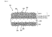
図4に例示されるように、本実施形態のガスセンサ素子10は、中間測定電極層312が、複数層から構成されている。
As illustrated in FIG. 4, in the gas sensor element 10 of the present embodiment, the intermediate measurement electrode layer 312 is configured of a plurality of layers.
この構成によれば、中間測定電極層312を構成する各層について気孔率を制御することが可能になるので、上述した作用効果を得やすいガスセンサ素子10が得られる。各層の気孔率の制御は、例えば、各層に含まれる貴金属粒子33と固体電解質粒子34との混合比率を調節することなどによって実施することができる。
According to this configuration, it is possible to control the porosity of each of the layers constituting the intermediate measurement electrode layer 312, so that it is possible to obtain the gas sensor element 10 that can easily obtain the above-described effects. The porosity of each layer can be controlled, for example, by adjusting the mixing ratio of the noble metal particles 33 and the solid electrolyte particles 34 contained in each layer.
図4では、中間測定電極層312は、内層312aおよび外層312bの少なくとも2層から構成されている例が示されている。中間測定電極層312は、図4に限定されることなく、3層以上から構成することもできる。
FIG. 4 shows an example in which the intermediate measurement electrode layer 312 is composed of at least two layers of an inner layer 312a and an outer layer 312b. The intermediate measurement electrode layer 312 can also be composed of three or more layers without being limited to FIG.
中間測定電極層312を構成する各層は、具体的には、表面測定電極層311に近くなるほど、気孔率を大きく、固体電解質体20に近くなるほど、気孔率を小さくすることができる。より具体的には、中間測定電極層312を構成する各層の気孔率は、固体電解質体20側から表面測定電極層311に向かって大きくなる構成とすることができる。但し、中間測定電極層312を構成する各層の気孔率は、表面測定電極層311の気孔率よりも小さくされる。中間測定電極層312を構成する各層の気孔率は、具体的には、いずれも15%以下とすることができる。その他の構成および作用効果は、実施形態1と同様である。
Specifically, the layers constituting the intermediate measurement electrode layer 312 can increase the porosity as they are closer to the surface measurement electrode layer 311 and can decrease the porosity as they are closer to the solid electrolyte body 20. More specifically, the porosity of each layer constituting the intermediate measurement electrode layer 312 can be configured to increase from the solid electrolyte body 20 side toward the surface measurement electrode layer 311. However, the porosity of each layer constituting the intermediate measurement electrode layer 312 is smaller than the porosity of the surface measurement electrode layer 311. Specifically, the porosity of each layer constituting the intermediate measurement electrode layer 312 can be 15% or less. The other configurations and effects are the same as in the first embodiment.
本実施形態のガスセンサ1は、上述した本実施形態のガスセンサ素子10を有している。その他の構成および作用効果は、実施形態1と同様である。
The gas sensor 1 of the present embodiment has the gas sensor element 10 of the present embodiment described above. The other configurations and effects are the same as in the first embodiment.
(実施形態3)
実施形態3のガスセンサ素子およびガスセンサについて、図5を用いて説明する。 (Embodiment 3)
The gas sensor element and the gas sensor ofEmbodiment 3 will be described with reference to FIG.
実施形態3のガスセンサ素子およびガスセンサについて、図5を用いて説明する。 (Embodiment 3)
The gas sensor element and the gas sensor of
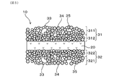
図5に例示されるように、本実施形態のガスセンサ素子10は、基準電極32が、基準ガスAとの接触面となる表面を備える表面基準電極層321と、表面基準電極層321の固体電解質体20側の面に接して配置された中間基準電極層322とを有している。ガスセンサ素子10において、表面基準電極層321の気孔率は、中間基準電極層322の気孔率よりも大きくされている。
As illustrated in FIG. 5, in the gas sensor element 10 of the present embodiment, the surface reference electrode layer 321 having the surface where the reference electrode 32 is a contact surface with the reference gas A, and the solid electrolyte of the surface reference electrode layer 321 And an intermediate reference electrode layer 322 disposed in contact with the surface on the body 20 side. In the gas sensor element 10, the porosity of the surface reference electrode layer 321 is larger than the porosity of the intermediate reference electrode layer 322.
本実施形態のガスセンサ素子10は、上記構成を有している。そのため、ガスセンサ素子10は、基準ガスAとの接触面となる表面を備える気孔率の大きな表面基準電極層321により、貴金属粒子33の表面と固体電解質粒子34の表面と気孔35との交わり点である三相点が増加し、基準ガスAの反応性が向上して電極反応抵抗を低下させることができる。また、ガスセンサ素子10は、表面基準電極層321よりも気孔率の小さな固体電解質体20側の中間基準電極層322により、電極導電性が確保され、電極比抵抗の増加を抑制することができる。
The gas sensor element 10 of the present embodiment has the above configuration. Therefore, in the gas sensor element 10, the surface reference electrode layer 321 having a large porosity provided with the surface to be the contact surface with the reference gas A, the intersection point of the surface of the noble metal particles 33 and the surface of the solid electrolyte particles 34 and the pores 35. A certain three-phase point is increased, the reactivity of the reference gas A is improved, and the electrode reaction resistance can be reduced. Further, in the gas sensor element 10, the intermediate reference electrode layer 322 on the side of the solid electrolyte body 20 having a smaller porosity than the surface reference electrode layer 321 can ensure the electrode conductivity and can suppress an increase in electrode specific resistance.
よって、本実施形態のガスセンサ素子10によれば、測定電極31および基準電極32の効果が相まって、電極反応抵抗をより低下させることができ、電極比抵抗の増加をより効果的に抑制することができる。
Therefore, according to the gas sensor element 10 of the present embodiment, the effects of the measurement electrode 31 and the reference electrode 32 can be combined to further reduce the electrode reaction resistance and to more effectively suppress the increase in the electrode specific resistance. it can.
なお、その他の構成および作用効果は、実施形態1と同様である。但し、表面基準電極層321の構成については、実施形態1における「表面測定電極層311」を「表面基準電極層321」と読み換えて適用することができる。同様に、中間基準電極層322の構成については、実施形態1における「中間測定電極層312」を「中間基準電極層322」と読み換えて適用することができる。
The other configurations and operational effects are the same as in the first embodiment. However, regarding the configuration of the surface reference electrode layer 321, the “surface measurement electrode layer 311” in Embodiment 1 can be read as “the surface reference electrode layer 321” and applied. Similarly, with regard to the configuration of the intermediate reference electrode layer 322, the “intermediate measurement electrode layer 312” in Embodiment 1 can be read as “the intermediate reference electrode layer 322” and applied.
本実施形態のガスセンサ1は、上述した本実施形態のガスセンサ素子10を有している。その他の構成および作用効果は、実施形態1と同様である。
The gas sensor 1 of the present embodiment has the gas sensor element 10 of the present embodiment described above. The other configurations and effects are the same as in the first embodiment.
(実験例1)
固体電解質体の一方面に、貴金属粒子と固体電解質粒子と造孔剤とを含む中間測定電極層形成用ペーストを厚み7μmでスクリーン印刷した後、さらに、貴金属粒子と固体電解質粒子と造孔剤とを含む表面測定電極層形成用ペーストを厚み7μmでスクリーン印刷した。なお、中間測定電極層形成用ペーストにおける貴金属粒子と固体電解質粒子との質量比は、97:3である。また、表面測定電極層形成用ペーストにおける貴金属粒子と固体電解質粒子との質量比は、96:4である。次いで、固体電解質体の他方面に、貴金属粒子と固体電解質粒子と造孔剤とを含む基準電極形成用ペーストを厚み7μmでスクリーン印刷した。なお、基準電極形成用ペーストにおける貴金属粒子と固体電解質粒子との質量比は、97:3である。上記において、固体電解質体には、イットリア部分安定化ジルコニアを用いた。貴金属粒子には、Pt粒子(一次粒子径:0.6~10μm)を用いた。固体電解質粒子には、イットリア安定化ジルコニア(一次粒子径:0.2~3μm)を用いた。次いで、各ペーストが印刷された固体電解質体を、1450℃で焼成した。これにより、試料1のガスセンサ素子を得た。 (Experimental example 1)
An intermediate measurement electrode layer forming paste containing noble metal particles, solid electrolyte particles, and a pore forming agent is screen-printed to a thickness of 7 μm on one surface of the solid electrolyte body, and then noble metal particles, solid electrolyte particles, and a pore forming agent The surface measurement electrode layer forming paste including the above was screen printed with a thickness of 7 .mu.m. The mass ratio of the noble metal particles to the solid electrolyte particles in the intermediate measurement electrode layer forming paste is 97: 3. The mass ratio of the noble metal particles to the solid electrolyte particles in the surface measurement electrode layer forming paste is 96: 4. Next, on the other surface of the solid electrolyte body, a paste for forming a reference electrode containing noble metal particles, solid electrolyte particles and a pore forming agent was screen-printed to a thickness of 7 μm. The mass ratio of the noble metal particles to the solid electrolyte particles in the reference electrode-forming paste is 97: 3. In the above, yttria partially stabilized zirconia was used for the solid electrolyte body. Pt particles (primary particle diameter: 0.6 to 10 μm) were used as the noble metal particles. Yttria-stabilized zirconia (primary particle diameter: 0.2 to 3 μm) was used for the solid electrolyte particles. Subsequently, the solid electrolyte body on which each paste was printed was fired at 1450 ° C. Thus, the gas sensor element ofSample 1 was obtained.
固体電解質体の一方面に、貴金属粒子と固体電解質粒子と造孔剤とを含む中間測定電極層形成用ペーストを厚み7μmでスクリーン印刷した後、さらに、貴金属粒子と固体電解質粒子と造孔剤とを含む表面測定電極層形成用ペーストを厚み7μmでスクリーン印刷した。なお、中間測定電極層形成用ペーストにおける貴金属粒子と固体電解質粒子との質量比は、97:3である。また、表面測定電極層形成用ペーストにおける貴金属粒子と固体電解質粒子との質量比は、96:4である。次いで、固体電解質体の他方面に、貴金属粒子と固体電解質粒子と造孔剤とを含む基準電極形成用ペーストを厚み7μmでスクリーン印刷した。なお、基準電極形成用ペーストにおける貴金属粒子と固体電解質粒子との質量比は、97:3である。上記において、固体電解質体には、イットリア部分安定化ジルコニアを用いた。貴金属粒子には、Pt粒子(一次粒子径:0.6~10μm)を用いた。固体電解質粒子には、イットリア安定化ジルコニア(一次粒子径:0.2~3μm)を用いた。次いで、各ペーストが印刷された固体電解質体を、1450℃で焼成した。これにより、試料1のガスセンサ素子を得た。 (Experimental example 1)
An intermediate measurement electrode layer forming paste containing noble metal particles, solid electrolyte particles, and a pore forming agent is screen-printed to a thickness of 7 μm on one surface of the solid electrolyte body, and then noble metal particles, solid electrolyte particles, and a pore forming agent The surface measurement electrode layer forming paste including the above was screen printed with a thickness of 7 .mu.m. The mass ratio of the noble metal particles to the solid electrolyte particles in the intermediate measurement electrode layer forming paste is 97: 3. The mass ratio of the noble metal particles to the solid electrolyte particles in the surface measurement electrode layer forming paste is 96: 4. Next, on the other surface of the solid electrolyte body, a paste for forming a reference electrode containing noble metal particles, solid electrolyte particles and a pore forming agent was screen-printed to a thickness of 7 μm. The mass ratio of the noble metal particles to the solid electrolyte particles in the reference electrode-forming paste is 97: 3. In the above, yttria partially stabilized zirconia was used for the solid electrolyte body. Pt particles (primary particle diameter: 0.6 to 10 μm) were used as the noble metal particles. Yttria-stabilized zirconia (primary particle diameter: 0.2 to 3 μm) was used for the solid electrolyte particles. Subsequently, the solid electrolyte body on which each paste was printed was fired at 1450 ° C. Thus, the gas sensor element of
試料1のガスセンサ素子の作製において、固体電解質体の一方面に、上記中間測定電極層形成用ペーストを厚み14μmでスクリーン印刷したのみとし、その後に表面測定電極層形成用ペーストをスクリーン印刷しなかった点以外は同様にして、試料1Cのガスセンサを得た。
In the preparation of the gas sensor element of Sample 1, the intermediate measurement electrode layer forming paste was only screen-printed to a thickness of 14 μm on one surface of the solid electrolyte body, and thereafter the surface measurement electrode layer forming paste was not screen-printed A gas sensor of sample 1C was obtained in the same manner except for the point.
SEMにて、各試料のガスセンサ素子の測定電極を断面観察した。図6および図7にその結果を示す。図7によれば、試料1Cのガスセンサ素子は、測定電極が単層より構成されていることがわかる。これに対し、図6に示されるように、試料1のガスセンサ素子は、測定電極が、貴金属粒子と、酸素イオン伝導性を有する固体電解質粒子と、気孔とを含んで構成されており、当該測定電極は、測定ガスとの接触面となる表面を備える表面測定電極層と、表面測定電極層の固体電解質体側の面に接して配置された中間測定電極層とを有していることがわかる。また、上述した測定方法によって測定した表面測定電極層の気孔率は22%、中間測定電極層の気孔率は8%であり、表面測定電極層の気孔率は、中間測定電極層の気孔率よりも大きかった。なお、図8に、測定電極31の反射電子像を、輝度分布にて、貴金属粒子領域330、固体電解質粒子領域340、気孔領域350の各領域に分離した一例を示す。図9に、表面測定電極層の気孔率を算出する際における、気孔領域の画像の一例を示す。
The cross section of the measurement electrode of the gas sensor element of each sample was observed by SEM. The results are shown in FIG. 6 and FIG. According to FIG. 7, it can be seen that in the gas sensor element of sample 1C, the measurement electrode is constituted by a single layer. On the other hand, as shown in FIG. 6, in the gas sensor element of sample 1, the measurement electrode includes noble metal particles, solid electrolyte particles having oxygen ion conductivity, and pores, and the measurement It can be seen that the electrode has a surface measurement electrode layer having a surface to be a contact surface with the measurement gas, and an intermediate measurement electrode layer disposed in contact with the surface of the surface measurement electrode layer on the solid electrolyte body side. In addition, the porosity of the surface measurement electrode layer measured by the above-described measurement method is 22%, the porosity of the intermediate measurement electrode layer is 8%, and the porosity of the surface measurement electrode layer is higher than the porosity of the intermediate measurement electrode layer It was big too. Note that FIG. 8 shows an example in which the reflection electron image of the measurement electrode 31 is divided into the noble metal particle region 330, the solid electrolyte particle region 340, and the pore region 350 in the luminance distribution. FIG. 9 shows an example of an image of the pore region when calculating the porosity of the surface measurement electrode layer.
各試料のガスセンサ素子について、測定電極の電極反応抵抗を測定した。具体的には、測定電極に対して周波数1MHz~0.1Hzのインピーダンス計測にて固体電解質粒子の粒内抵抗、固体電解質粒子の粒界抵抗、電極反応抵抗を550~800℃にて測定し、電極反応抵抗を、図9に示されるようなCole-Coleプロットにより解析した。なお、図9において、R1は、固体電解質粒子の粒内抵抗である。R2は、固体電解質粒子の粒界抵抗である。R3は、電極反応抵抗である。Zwは、ガス拡散抵抗である。ZReは、インピーダンスの実数成分である。ZImは、インピーダンスの虚数成分である。
The electrode reaction resistance of the measurement electrode was measured for the gas sensor element of each sample. Specifically, the intergranular resistance of the solid electrolyte particles, the intergranular resistance of the solid electrolyte particles, and the electrode reaction resistance of the measurement electrode are measured at 550 to 800 ° C. by impedance measurement at a frequency of 1 MHz to 0.1 Hz. The electrode reaction resistance was analyzed by Cole-Cole plot as shown in FIG. In FIG. 9, R1 is the intragranular resistance of the solid electrolyte particles. R2 is the grain boundary resistance of solid electrolyte particles. R3 is an electrode reaction resistance. Zw is a gas diffusion resistance. Z Re is a real component of impedance. Z Im is an imaginary component of impedance.
図11に、センサ温度(℃)と電極反応抵抗(Ω)との関係を示す。図11に示されるように、試料1のガスセンサ素子は、試料1Cのガスセンサ素子に比べ、全センサ温度域において電極反応抵抗が低いことがわかる。
FIG. 11 shows the relationship between the sensor temperature (° C.) and the electrode reaction resistance (Ω). As shown in FIG. 11, it can be seen that the gas sensor element of sample 1 has lower electrode reaction resistance in the entire sensor temperature range as compared to the gas sensor element of sample 1C.
各試料のガスセンサ素子について、測定電極の電極比抵抗を測定した。具体的には、固体電解質体上に形成された測定電極の両端の電気抵抗を測定し、計測した測定電極の大きさ(幅、長さ、厚さ)から、以下の式にて電極比抵抗を求めた。
[電極比抵抗(Ω・cm)]=[電気抵抗(Ω)]×[幅(cm)]×[厚さ(cm)]/[長さ(cm)] The electrode specific resistance of the measurement electrode was measured about the gas sensor element of each sample. Specifically, the electrical resistance of both ends of the measurement electrode formed on the solid electrolyte body is measured, and the electrode specific resistance is calculated according to the following equation from the size (width, length, thickness) of the measurement electrode measured. I asked for.
[Electrode specific resistance (Ω · cm)] = [electrical resistance (Ω)] × [width (cm)] × [thickness (cm)] / [length (cm)]
その結果、試料1のガスセンサ素子における測定電極の電極比抵抗は、21(Ω・cm)、試料1Cのガスセンサ素子における測定電極の電極比抵抗は、20(Ω・cm)であった。この結果から、、試料1のガスセンサ素子は、試料1Cのガスセンサ素子に比べ、電極比抵抗の増加を抑制することができていることがわかる。
As a result, the electrode specific resistance of the measurement electrode in the gas sensor element of sample 1 was 21 (Ω · cm), and the electrode specific resistance of the measurement electrode in the gas sensor element of sample 1C was 20 (Ω · cm). From this result, it can be seen that the gas sensor element of sample 1 can suppress an increase in electrode specific resistance as compared to the gas sensor element of sample 1C.
(実験例2)
試料1のガスセンサ素子の作製に準じ、表面測定電極層の気孔率が異なる複数のガスセンサ素子を作製し、表面測定電極層の気孔率と電極反応抵抗との関係を求めた。その結果を、図12に示す。 (Experimental example 2)
A plurality of gas sensor elements different in the porosity of the surface measurement electrode layer were manufactured according to the production of the gas sensor element of thesample 1, and the relationship between the porosity of the surface measurement electrode layer and the electrode reaction resistance was determined. The results are shown in FIG.
試料1のガスセンサ素子の作製に準じ、表面測定電極層の気孔率が異なる複数のガスセンサ素子を作製し、表面測定電極層の気孔率と電極反応抵抗との関係を求めた。その結果を、図12に示す。 (Experimental example 2)
A plurality of gas sensor elements different in the porosity of the surface measurement electrode layer were manufactured according to the production of the gas sensor element of the
図12に示されるように、ガスセンサ素子において、表面測定電極層の気孔率が15%以上30%以下とされている場合には、電極反応抵抗を低下させやすくなることがわかる。これは、上記場合には、測定ガスとの接触機会の増加によって測定ガスの反応性が向上するためである。
As shown in FIG. 12, in the gas sensor element, when the porosity of the surface measurement electrode layer is 15% or more and 30% or less, it is understood that the electrode reaction resistance is easily lowered. This is because, in the above case, the reactivity of the measurement gas is improved by an increase in the chance of contact with the measurement gas.
(実験例3)
試料1のガスセンサ素子の作製に準じ、中間測定電極層の気孔率が異なる複数のガスセンサ素子を作製し、中間測定電極層の気孔率と電極比抵抗との関係を求めた。その結果を、図13に示す。 (Experimental example 3)
A plurality of gas sensor elements different in the porosity of the intermediate measurement electrode layer were manufactured according to the production of the gas sensor element of thesample 1, and the relationship between the porosity of the intermediate measurement electrode layer and the electrode specific resistance was determined. The results are shown in FIG.
試料1のガスセンサ素子の作製に準じ、中間測定電極層の気孔率が異なる複数のガスセンサ素子を作製し、中間測定電極層の気孔率と電極比抵抗との関係を求めた。その結果を、図13に示す。 (Experimental example 3)
A plurality of gas sensor elements different in the porosity of the intermediate measurement electrode layer were manufactured according to the production of the gas sensor element of the
図13に示されるように、ガスセンサ素子において、中間測定電極層の気孔率が15%以下とされている場合には、電極比抵抗の増加を抑制しやすくなることがわかる。これは、上記場合には、適度な気孔量によって中間測定電極層内における電子導電経路が確保されやすくなるためである。
As shown in FIG. 13, in the gas sensor element, when the porosity of the intermediate measurement electrode layer is 15% or less, it is understood that the increase in the electrode specific resistance can be easily suppressed. This is because, in the above case, the electron conduction path in the intermediate measurement electrode layer can be easily secured by an appropriate amount of pores.
(実験例4)
試料1のガスセンサ素子を組み込んだ試料1のガスセンサを用い、大気中で温度を600℃、650℃、700℃とした場合におけるガスセンサの印加電圧とセンサ電流との関係を測定した。その結果を、図14に示す。また、試料1Cのガスセンサ素子を組み込んだ試料1Cのガスセンサを用い、大気中で温度を600℃、650℃、700℃とした場合におけるガスセンサの印加電圧とセンサ電流との関係を測定した。その結果を、図15に示す。なお、本実験例では、ガスセンサは、A/F(空燃比)センサとして使用されるものであり、0.4Vの電流値を測定することで、空燃比を求めるよう構成されている。 (Experimental example 4)
The relationship between the voltage applied to the gas sensor and the sensor current was measured when the temperature was set to 600 ° C., 650 ° C., and 700 ° C. in the atmosphere using the gas sensor ofsample 1 incorporating the gas sensor element of sample 1. The results are shown in FIG. Further, using the gas sensor of sample 1C incorporating the gas sensor element of sample 1C, the relationship between the voltage applied to the gas sensor and the sensor current was measured when the temperature was set to 600 ° C., 650 ° C., and 700 ° C. in the atmosphere. The results are shown in FIG. In the present experimental example, the gas sensor is used as an A / F (air-fuel ratio) sensor, and is configured to obtain an air-fuel ratio by measuring a current value of 0.4 V.
試料1のガスセンサ素子を組み込んだ試料1のガスセンサを用い、大気中で温度を600℃、650℃、700℃とした場合におけるガスセンサの印加電圧とセンサ電流との関係を測定した。その結果を、図14に示す。また、試料1Cのガスセンサ素子を組み込んだ試料1Cのガスセンサを用い、大気中で温度を600℃、650℃、700℃とした場合におけるガスセンサの印加電圧とセンサ電流との関係を測定した。その結果を、図15に示す。なお、本実験例では、ガスセンサは、A/F(空燃比)センサとして使用されるものであり、0.4Vの電流値を測定することで、空燃比を求めるよう構成されている。 (Experimental example 4)
The relationship between the voltage applied to the gas sensor and the sensor current was measured when the temperature was set to 600 ° C., 650 ° C., and 700 ° C. in the atmosphere using the gas sensor of
図15に示されるように、試料1Cのガスセンサは、600℃、650℃の低温では、安定した出力を得ることができないことがわかる。これに対し、図14に示されるように、試料1のガスセンサは、600℃、650℃、700℃の全温度域において、安定した出力を得ることができることがわかる。この結果から、試料1のガスセンサは、低温における電極活性が高く、センサの低温作動化に有利であり、ヒータの使用量を低減して、省エネ化を図ることができるといえる。
As shown in FIG. 15, it can be seen that the gas sensor of Sample 1C can not obtain stable output at low temperatures of 600 ° C. and 650 ° C. On the other hand, as shown in FIG. 14, it can be seen that the gas sensor of Sample 1 can obtain stable output in all temperature ranges of 600 ° C., 650 ° C. and 700 ° C. From this result, it can be said that the gas sensor of the sample 1 has high electrode activity at low temperatures, is advantageous for low temperature operation of the sensors, and can save energy by reducing the amount of heater used.
本開示は、上記各実施形態、各実験例に限定されるものではなく、その要旨を逸脱しない範囲において種々の変更が可能である。すなわち、本開示は、実施形態に準拠して記述されたが、本開示は、当該実施形態や構造等に限定されるものではないと理解される。本開示は、様々は変形例や均等範囲内の変形をも包含する。加えて、様々な組み合わせや形態、さらには、それらに一要素のみ、それ以上、あるいはそれ以下、を含む他の組み合わせや形態をも、本開示の範疇や思想範囲に入るものである。また、各実施形態、各実験例に示される各構成は、それぞれ任意に組み合わせることができる。例えば、実施形態1における基準電極の構成を、実施形態3における基準電極の構成に置換することができる。また、実施形態2における基準電極の構成を、実施形態3における基準電極の構成に置換することができる。また、上記各変形例において、各基準電極を構成する中間基準電極層は、複数層から構成することができる。
The present disclosure is not limited to the above embodiments and experimental examples, and various modifications can be made without departing from the scope of the invention. That is, although the present disclosure has been described based on the embodiments, it is understood that the present disclosure is not limited to the embodiments, structures, and the like. The present disclosure includes various modifications and variations within the equivalent range. In addition, various combinations and forms, and further, other combinations and forms including only one element, or more or less than these elements are also within the scope and the scope of the present disclosure. Moreover, each structure shown by each embodiment and each experiment example can each be combined arbitrarily. For example, the configuration of the reference electrode in the first embodiment can be replaced with the configuration of the reference electrode in the third embodiment. The configuration of the reference electrode in the second embodiment can be replaced with the configuration of the reference electrode in the third embodiment. Further, in each of the above-described modifications, the intermediate reference electrode layer constituting each reference electrode can be constituted of a plurality of layers.
Claims (10)
- 酸素イオン伝導性を有する固体電解質体(20)と、上記固体電解質体の一方面に設けられて測定ガス(G)に曝される測定電極(31)と、上記固体電解質体の他方面に設けられて基準ガス(A)に曝される基準電極(32)とを有しており、
上記測定電極および上記基準電極は、いずれも、貴金属粒子(33)と、酸素イオン伝導性を有する固体電解質粒子(34)と、気孔(35)とを含んで構成されており、
上記測定電極は、
上記測定ガスとの接触面となる表面を備える表面測定電極層(311)と、上記表面測定電極層の上記固体電解質体側の面に接して配置された中間測定電極層(312)と、を有しており、
上記表面測定電極層の気孔率は、上記中間測定電極層の気孔率よりも大きい、ガスセンサ素子(10)。 A solid electrolyte body (20) having oxygen ion conductivity, a measurement electrode (31) provided on one side of the solid electrolyte body and exposed to a measurement gas (G), provided on the other side of the solid electrolyte body And a reference electrode (32) exposed to the reference gas (A),
Each of the measurement electrode and the reference electrode includes noble metal particles (33), solid electrolyte particles (34) having oxygen ion conductivity, and pores (35),
The above measurement electrode is
A surface measurement electrode layer (311) having a surface to be a contact surface with the measurement gas, and an intermediate measurement electrode layer (312) disposed in contact with the surface of the surface measurement electrode layer on the solid electrolyte body side Yes,
The gas sensor element (10), wherein the porosity of the surface measurement electrode layer is larger than the porosity of the intermediate measurement electrode layer. - 上記表面測定電極層の気孔率が、15%以上30%以下である、請求項1に記載のガスセンサ素子。 The gas sensor element according to claim 1, wherein the porosity of the surface measurement electrode layer is 15% or more and 30% or less.
- 上記中間測定電極層の気孔率が、15%以下である、請求項1または2に記載のガスセンサ素子。 The gas sensor element according to claim 1, wherein the porosity of the intermediate measurement electrode layer is 15% or less.
- 上記中間測定電極層は、複数層から構成されている、請求項1~3のいずれか1項に記載のガスセンサ素子。 The gas sensor element according to any one of claims 1 to 3, wherein the intermediate measurement electrode layer is composed of a plurality of layers.
- 上記基準電極は、
上記基準ガスとの接触面となる表面を備える表面基準電極層(321)と、上記表面基準電極層の上記固体電解質体側の面に接して配置された中間基準電極層(322)と、を有しており、
上記表面基準電極層の気孔率は、上記中間基準電極層の気孔率よりも大きい、請求項1~4のいずれか1項に記載のガスセンサ素子。 The reference electrode is
A surface reference electrode layer (321) having a surface to be a contact surface with the reference gas, and an intermediate reference electrode layer (322) disposed in contact with the surface of the surface reference electrode layer on the solid electrolyte body side Yes,
The gas sensor element according to any one of claims 1 to 4, wherein the porosity of the surface reference electrode layer is larger than the porosity of the intermediate reference electrode layer. - 上記表面基準電極層の気孔率が、15%以上30%以下である、請求項5に記載のガスセンサ素子。 The gas sensor element according to claim 5, wherein the porosity of the surface reference electrode layer is 15% or more and 30% or less.
- 上記中間基準電極層の気孔率が、15%以下である、請求項5または6に記載のガスセンサ素子。 The gas sensor element according to claim 5 or 6, wherein the porosity of the intermediate reference electrode layer is 15% or less.
- 上記中間基準電極層は、複数層から構成されている、請求項5~7のいずれか1項に記載のガスセンサ素子。 The gas sensor element according to any one of claims 5 to 7, wherein the intermediate reference electrode layer is composed of a plurality of layers.
- 上記貴金属粒子を構成する貴金属は、Pt、または、Ptと、Rh、Pd、Au、および、Agからなる群より選択される少なくとも1種との合金である、請求項1~8のいずれか1項に記載のガスセンサ素子。 The noble metal according to any one of claims 1 to 8, wherein the noble metal constituting the noble metal particles is Pt or an alloy of Pt and at least one selected from the group consisting of Rh, Pd, Au, and Ag. The gas sensor element as described in a term.
- 請求項1~9のいずれか1項に記載のガスセンサ素子を有するガスセンサ(1)。 A gas sensor (1) comprising the gas sensor element according to any one of claims 1 to 9.
Priority Applications (2)
| Application Number | Priority Date | Filing Date | Title |
|---|---|---|---|
| DE112018005171.4T DE112018005171T5 (en) | 2017-09-15 | 2018-09-05 | GAS SENSOR ELEMENT AND GAS SENSOR |
| US16/813,995 US20200209184A1 (en) | 2017-09-15 | 2020-03-10 | Gas sensor element and gas sensor |
Applications Claiming Priority (2)
| Application Number | Priority Date | Filing Date | Title |
|---|---|---|---|
| JP2017178178A JP6752184B2 (en) | 2017-09-15 | 2017-09-15 | Gas sensor element and gas sensor |
| JP2017-178178 | 2017-09-15 |
Related Child Applications (1)
| Application Number | Title | Priority Date | Filing Date |
|---|---|---|---|
| US16/813,995 Continuation US20200209184A1 (en) | 2017-09-15 | 2020-03-10 | Gas sensor element and gas sensor |
Publications (1)
| Publication Number | Publication Date |
|---|---|
| WO2019054255A1 true WO2019054255A1 (en) | 2019-03-21 |
Family
ID=65723615
Family Applications (1)
| Application Number | Title | Priority Date | Filing Date |
|---|---|---|---|
| PCT/JP2018/032909 WO2019054255A1 (en) | 2017-09-15 | 2018-09-05 | Gas sensor element and gas sensor |
Country Status (4)
| Country | Link |
|---|---|
| US (1) | US20200209184A1 (en) |
| JP (1) | JP6752184B2 (en) |
| DE (1) | DE112018005171T5 (en) |
| WO (1) | WO2019054255A1 (en) |
Families Citing this family (1)
| Publication number | Priority date | Publication date | Assignee | Title |
|---|---|---|---|---|
| US11328906B2 (en) * | 2018-07-30 | 2022-05-10 | Toto Ltd. | Electrostatic chuck |
Citations (5)
| Publication number | Priority date | Publication date | Assignee | Title |
|---|---|---|---|---|
| JP2002005878A (en) * | 2000-04-22 | 2002-01-09 | Robert Bosch Gmbh | Electrochemical measurement sensor |
| JP2004061323A (en) * | 2002-07-29 | 2004-02-26 | Kyocera Corp | Oxygen sensor element |
| JP2017020838A (en) * | 2015-07-08 | 2017-01-26 | 株式会社日本自動車部品総合研究所 | Pump electrode and reference electrode for gas sensor |
| JP2017090405A (en) * | 2015-11-17 | 2017-05-25 | 日本碍子株式会社 | Gas sensor detection electrode, gas sensor and production method of gas sensor |
| JP2017518506A (en) * | 2014-06-18 | 2017-07-06 | ローベルト ボツシユ ゲゼルシヤフト ミツト ベシユレンクテル ハフツングRobert Bosch Gmbh | Sensor element for detecting at least one characteristic of a measurement gas in a measurement gas space |
Family Cites Families (2)
| Publication number | Priority date | Publication date | Assignee | Title |
|---|---|---|---|---|
| JP4409581B2 (en) | 2007-02-05 | 2010-02-03 | 京セラ株式会社 | Oxygen sensor element |
| JP6282302B2 (en) | 2016-03-31 | 2018-02-21 | 本田技研工業株式会社 | Body structure and vehicle manufacturing method |
-
2017
- 2017-09-15 JP JP2017178178A patent/JP6752184B2/en active Active
-
2018
- 2018-09-05 DE DE112018005171.4T patent/DE112018005171T5/en active Pending
- 2018-09-05 WO PCT/JP2018/032909 patent/WO2019054255A1/en active Application Filing
-
2020
- 2020-03-10 US US16/813,995 patent/US20200209184A1/en active Pending
Patent Citations (5)
| Publication number | Priority date | Publication date | Assignee | Title |
|---|---|---|---|---|
| JP2002005878A (en) * | 2000-04-22 | 2002-01-09 | Robert Bosch Gmbh | Electrochemical measurement sensor |
| JP2004061323A (en) * | 2002-07-29 | 2004-02-26 | Kyocera Corp | Oxygen sensor element |
| JP2017518506A (en) * | 2014-06-18 | 2017-07-06 | ローベルト ボツシユ ゲゼルシヤフト ミツト ベシユレンクテル ハフツングRobert Bosch Gmbh | Sensor element for detecting at least one characteristic of a measurement gas in a measurement gas space |
| JP2017020838A (en) * | 2015-07-08 | 2017-01-26 | 株式会社日本自動車部品総合研究所 | Pump electrode and reference electrode for gas sensor |
| JP2017090405A (en) * | 2015-11-17 | 2017-05-25 | 日本碍子株式会社 | Gas sensor detection electrode, gas sensor and production method of gas sensor |
Also Published As
| Publication number | Publication date |
|---|---|
| JP2019052973A (en) | 2019-04-04 |
| DE112018005171T5 (en) | 2020-06-10 |
| JP6752184B2 (en) | 2020-09-09 |
| US20200209184A1 (en) | 2020-07-02 |
Similar Documents
| Publication | Publication Date | Title |
|---|---|---|
| JP6047103B2 (en) | Gas sensor electrode and gas sensor | |
| JP6382162B2 (en) | Gas sensor pump electrode and reference electrode | |
| JP5638984B2 (en) | Gas sensor | |
| JP5938133B1 (en) | Detection electrode of gas sensor, gas sensor, and method of manufacturing gas sensor | |
| US10788443B2 (en) | Gas sensor element and gas sensor | |
| JP2009186458A (en) | Gas sensor element and gas sensor | |
| CN108700546B (en) | Gas sensor element and method for manufacturing same | |
| US20210318262A1 (en) | Gas sensor element and gas sensor | |
| JP6678134B2 (en) | Gas sensor element and gas sensor | |
| JP5278499B2 (en) | Gas sensor element and gas sensor using the same | |
| JP6540661B2 (en) | Gas sensor element and gas sensor | |
| US11643365B2 (en) | Solid electrolyte, producing method thereof, and gas sensor | |
| JP2009192518A (en) | Gas sensor element and gas sensor | |
| WO2019054255A1 (en) | Gas sensor element and gas sensor | |
| JP6471077B2 (en) | Gas sensor element and gas sensor provided with gas sensor element | |
| JP2021124382A (en) | Gas sensor | |
| JP2011169757A (en) | Resistive oxygen sensor element | |
| JP2017510813A (en) | Sensor element for detecting at least one characteristic of a measurement gas in a measurement gas space and method for manufacturing the sensor element | |
| US20190004008A1 (en) | Gas sensor element and gas sensor | |
| US11656196B2 (en) | Solid electrolyte, manufacturing method thereof, and gas sensor | |
| JP5724832B2 (en) | Oxygen concentration sensor | |
| JP2010256111A (en) | Gas sensor element, gas sensor having the same built, and method for manufacturing the gas sensor element | |
| JP2020085504A (en) | Gas sensor | |
| JP2004294122A (en) | Oxygen sensor element |
Legal Events
| Date | Code | Title | Description |
|---|---|---|---|
| 121 | Ep: the epo has been informed by wipo that ep was designated in this application |
Ref document number: 18855790 Country of ref document: EP Kind code of ref document: A1 |
|
| 122 | Ep: pct application non-entry in european phase |
Ref document number: 18855790 Country of ref document: EP Kind code of ref document: A1 |