WO2019054122A1 - 脈波測定用電極ユニットおよび脈波測定装置 - Google Patents
脈波測定用電極ユニットおよび脈波測定装置 Download PDFInfo
- Publication number
- WO2019054122A1 WO2019054122A1 PCT/JP2018/030525 JP2018030525W WO2019054122A1 WO 2019054122 A1 WO2019054122 A1 WO 2019054122A1 JP 2018030525 W JP2018030525 W JP 2018030525W WO 2019054122 A1 WO2019054122 A1 WO 2019054122A1
- Authority
- WO
- WIPO (PCT)
- Prior art keywords
- electrodes
- pulse wave
- measurement
- electrode unit
- support member
- Prior art date
Links
Images


Classifications
-
- A—HUMAN NECESSITIES
- A61—MEDICAL OR VETERINARY SCIENCE; HYGIENE
- A61B—DIAGNOSIS; SURGERY; IDENTIFICATION
- A61B5/00—Measuring for diagnostic purposes; Identification of persons
- A61B5/02—Detecting, measuring or recording pulse, heart rate, blood pressure or blood flow; Combined pulse/heart-rate/blood pressure determination; Evaluating a cardiovascular condition not otherwise provided for, e.g. using combinations of techniques provided for in this group with electrocardiography or electroauscultation; Heart catheters for measuring blood pressure
- A61B5/024—Detecting, measuring or recording pulse rate or heart rate
- A61B5/02438—Detecting, measuring or recording pulse rate or heart rate with portable devices, e.g. worn by the patient
-
- A—HUMAN NECESSITIES
- A61—MEDICAL OR VETERINARY SCIENCE; HYGIENE
- A61B—DIAGNOSIS; SURGERY; IDENTIFICATION
- A61B5/00—Measuring for diagnostic purposes; Identification of persons
- A61B5/02—Detecting, measuring or recording pulse, heart rate, blood pressure or blood flow; Combined pulse/heart-rate/blood pressure determination; Evaluating a cardiovascular condition not otherwise provided for, e.g. using combinations of techniques provided for in this group with electrocardiography or electroauscultation; Heart catheters for measuring blood pressure
- A61B5/024—Detecting, measuring or recording pulse rate or heart rate
- A61B5/0245—Detecting, measuring or recording pulse rate or heart rate by using sensing means generating electric signals, i.e. ECG signals
-
- A—HUMAN NECESSITIES
- A61—MEDICAL OR VETERINARY SCIENCE; HYGIENE
- A61B—DIAGNOSIS; SURGERY; IDENTIFICATION
- A61B5/00—Measuring for diagnostic purposes; Identification of persons
- A61B5/68—Arrangements of detecting, measuring or recording means, e.g. sensors, in relation to patient
- A61B5/6801—Arrangements of detecting, measuring or recording means, e.g. sensors, in relation to patient specially adapted to be attached to or worn on the body surface
- A61B5/6802—Sensor mounted on worn items
- A61B5/681—Wristwatch-type devices
-
- A—HUMAN NECESSITIES
- A61—MEDICAL OR VETERINARY SCIENCE; HYGIENE
- A61B—DIAGNOSIS; SURGERY; IDENTIFICATION
- A61B5/00—Measuring for diagnostic purposes; Identification of persons
- A61B5/68—Arrangements of detecting, measuring or recording means, e.g. sensors, in relation to patient
- A61B5/6801—Arrangements of detecting, measuring or recording means, e.g. sensors, in relation to patient specially adapted to be attached to or worn on the body surface
- A61B5/6843—Monitoring or controlling sensor contact pressure
-
- A—HUMAN NECESSITIES
- A61—MEDICAL OR VETERINARY SCIENCE; HYGIENE
- A61B—DIAGNOSIS; SURGERY; IDENTIFICATION
- A61B5/00—Measuring for diagnostic purposes; Identification of persons
- A61B5/02—Detecting, measuring or recording pulse, heart rate, blood pressure or blood flow; Combined pulse/heart-rate/blood pressure determination; Evaluating a cardiovascular condition not otherwise provided for, e.g. using combinations of techniques provided for in this group with electrocardiography or electroauscultation; Heart catheters for measuring blood pressure
- A61B5/021—Measuring pressure in heart or blood vessels
- A61B5/02108—Measuring pressure in heart or blood vessels from analysis of pulse wave characteristics
- A61B5/02125—Measuring pressure in heart or blood vessels from analysis of pulse wave characteristics of pulse wave propagation time
Definitions
- the present disclosure relates to a pulse wave measurement electrode unit and a pulse wave measurement device for measuring pulse wave propagation time.
- Patent Document 1 Japanese Patent Application Laid-Open No. 2008-136655 is given as a document disclosing a conventional pulse wave measurement electrode unit.
- the pulse wave measurement electrode unit disclosed in Patent Document 1 includes a planar support member having a first main surface and a second main surface that are in a front-back relationship with each other in the thickness direction.
- a plurality of electrodes for pulse wave measurement are formed on the first main surface of the support member, and an air bag is disposed on the second main surface side of the support member.
- the electrode group is pressed against the surface of the wrist as the air bag expands.
- the plurality of electrodes extend continuously along the direction in which the plurality of electrodes are arranged without changing the thickness or the like. Supported by
- each electrode when attaching the pulse wave measurement electrode unit to the subject, each electrode can not be moved individually, and when there are irregularities on the body surface, etc., some of the electrodes are on the body surface. There is a concern that it will be difficult to adhere properly. In this case, there is a concern that the detection accuracy of the biological information may be reduced.
- the present disclosure has been made in view of the above problems, and an object of the present disclosure is to provide a pulse wave measurement electrode unit and pulse wave measurement device capable of appropriately bringing a plurality of electrodes into close contact with a body surface. It is to provide.
- the pulse wave measurement electrode unit is mounted by being wound around the measurement subject when measuring the pulse wave of the measurement subject, and the pair of current application electrodes and the first And a plurality of electrodes in contact with the body surface of the subject during measurement, and a first main surface facing the body surface of the subject in a state of being mounted on the subject; It has a second main surface opposite to the first main surface in the thickness direction and a supporting member for supporting the plurality of electrodes on the first main surface side, and is expanded by taking a fluid in and out. And a fluid bag configured to be compressible and configured to press the plurality of electrodes toward the surface of the subject by expanding upon measurement.
- the support member has a length direction that is a circumferential direction and a width direction that is orthogonal to the length direction in a state where the support member is attached to the subject.
- the plurality of electrodes are arranged side by side in the width direction. Low rigidity parts having lower rigidity than portions overlapping the electrodes in the thickness direction are provided between the adjacent electrodes.
- the fluid bags are disposed apart from each other in the width direction, and the plurality of electrodes and the first main surface of the support member You may have several division
- the low rigidity of the low rigidity portion is preferably provided by providing a gap between the divided bags adjacent to each other.
- the plurality of electrodes may be provided on the first main surface, and the fluid bag is disposed on the second main surface side. It may be In this case, the low rigidity of the low rigidity portion may be provided by providing a notch or an opening in the support member in a portion located between the adjacent electrodes. .
- the fluid bag has a notch or opening corresponding to the notch or the opening provided in the support member. It is also good.
- the plurality of electrodes may include a second pair of voltage measurement electrodes.
- the first pair of voltage measurement electrodes and the second pair of voltage measurement electrodes may be disposed between the pair of current application electrodes.
- a pulse wave measurement device based on the present disclosure includes: the above-described pulse wave measurement electrode unit; and a belt member configured to support the pulse wave measurement electrode unit and to be wound around a measurement target of a person to be measured. Prepare.
- a pulse wave measurement electrode unit and a pulse wave measurement device capable of appropriately bringing a plurality of electrodes into close contact with a body surface.
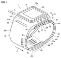
- FIG. 1 is a perspective view showing an appearance of a sphygmomanometer according to a first embodiment. It is a figure which shows typically the cross section perpendicular
- FIG. 2 is a block diagram showing a control configuration of the sphygmomanometer according to the first embodiment.
- FIG. 1 is a perspective view showing an appearance of a sphygmomanometer according to a first embodiment. It is a figure which shows typically the cross section perpendicular
- FIG. 7 is a view schematically showing a cross section along the longitudinal direction of the wrist when blood pressure measurement based on pulse wave propagation time is performed in a state where the sphygmomanometer according to Embodiment 1 is attached to the left wrist. It is a figure which shows the waveform of a 1st pulse wave signal and the waveform of a 2nd pulse wave signal which a 1st pulse wave sensor and a 2nd pulse wave sensor each output in the blood pressure measurement in FIG. 5A. It is a figure which shows typically the cross section along the longitudinal direction of the wrist at the time of measuring the blood pressure by the oscillometric method in the state with which the sphygmomanometer which concerns on Embodiment 1 was mounted
- FIG. 6 is a diagram showing an operation flow when the blood pressure monitor according to the first embodiment acquires a pulse wave propagation time (PTT) and performs blood pressure measurement (estimate) based on the pulse wave propagation time.
- FIG. 2 is a perspective view showing an electrode unit for pulse wave measurement according to the first embodiment.
- FIG. 7 is a perspective view showing an electrode unit for pulse wave measurement according to a second embodiment.
- FIG. 16 is a perspective view showing an electrode unit for pulse wave measurement according to a third embodiment.
- FIG. 16 is a perspective view showing an electrode unit for pulse wave measurement according to a fourth embodiment.
- FIG. 1 is a perspective view showing the appearance of the sphygmomanometer according to the first embodiment.
- FIG. 2 is a view schematically showing a cross section perpendicular to the longitudinal direction of the wrist in a state where the sphygmomanometer according to the first embodiment is attached to the left wrist.
- the sphygmomanometer 1 as a pulse wave measuring device mainly includes a belt 20 that is mounted around a user's left wrist 90 and a main body 10 integrally attached to the belt 20. And a pulse wave measurement electrode unit 200.
- the belt 20 has an elongated band shape so as to surround the left wrist 90 along the housing.
- the dimension (width dimension) in the width direction Y of the belt 20 is, for example, about 30 mm.
- Belt 20 includes a strip 23 forming outer circumferential surface 20 b, and a compression cuff 21 attached along inner circumferential surface 23 a of the strip 23 and constituting inner circumferential surface 20 a in contact with left wrist 90. .
- the compression cuff 21 has, like the belt 20, an elongated band shape so as to surround along the circumferential direction of the left wrist 90.
- the main body 10 is integrally provided at one end 20 e of the belt 20 in the circumferential direction, for example, by integral molding.
- the belt 20 and the main body 10 may be separately formed, and the main body 10 may be integrally attached to the belt 20 using an engaging member such as a hinge.
- the portion where the main body 10 is disposed corresponds to the back side surface (surface on the back side of the hand) 90 b of the left wrist 90 in the mounted state.
- Radial artery 91 passes near the palmar side (palm side) 90 a in the left wrist 90.
- the main body 10 has a thickness in the direction perpendicular to the outer circumferential surface 20 b of the belt 20.
- the main body 10 is small and thin so as not to interfere with the daily life of the user.
- the main body 10 has a quadrangular frustum-shaped contour protruding outward from the belt 20.
- a display 50 having a display screen is provided on the top surface 10a of the main body 10 (surface farthest from the measurement site). Further, an operation unit 52 for inputting an instruction from the user is provided along the side surface 10f of the main body 10 (the side surface on the left front side in FIG. 1).
- a pulse wave measurement electrode unit 200 is provided.
- the belt 20 supports the pulse wave measurement electrode unit 200.
- the pulse wave measurement electrode unit 200 includes a plurality of electrodes 41 to 46 (hereinafter all of which may be referred to as “electrode group 40E”), a pressure cuff 24 as a fluid bag, and a support member 210.
- electrode group 40E electrodes 41 to 46
- pressure cuff 24 as a fluid bag
- support member 210 The detailed configuration of the pulse wave measurement electrode unit 200 will be described later with reference to FIG.
- the pulse wave measurement electrode unit 200 includes an impedance measurement unit 40 that constitutes a first pulse wave sensor 401 (see FIG. 3) and a second pulse wave sensor 402 (see FIG. 3).
- each of the plurality of electrodes 41 to 46 has a plate-like shape.
- the pressure cuff 24 is disposed on the inner circumferential surface 20 a of the compression cuff 21 that constitutes the inner circumferential surface 20 a of the belt 20.
- the pressure cuff 24 is a fluid bag that expands and contracts in the thickness direction of the belt 20.
- the pressure cuff 24 is formed by facing two stretchable polyurethane sheets in the thickness direction and welding their peripheral portions.
- the pressure cuff 24 is pressurized or non-pressurized by supply or discharge of fluid.
- a bottom surface (a surface closest to the measurement site) 10 b of the main body 10 and an end 20 f of the belt 20 are connected by a three-fold buckle 15.
- the buckle 15 includes a first plate-like member 25 disposed on the outer circumferential side and a second plate-like member 26 disposed on the inner circumferential side.
- One end 25 e of the first plate-like member 25 is rotatably attached to the main body 10 via a connecting rod 27 extending along the width direction Y.
- the other end 25 f of the first plate-like member 25 is pivotable relative to one end 26 e of the second plate-like member 26 via the connecting rod 28 extending along the width direction Y. It is attached.
- the other end 26 f of the second plate-like member 26 is fixed near the end 20 f of the belt 20 by the fixing portion 29.
- the attachment position of the fixing portion 29 in the circumferential direction of the belt 20 is variably set in advance in accordance with the circumferential length of the left wrist 90 of the user.
- the sphygmomanometer 1 (belt 20) is generally formed in a substantially annular shape, and the bottom surface 10b of the main body 10 and the end 20f of the belt 20 can be opened and closed in the arrow B direction by the buckle 15. .
- the user passes the left hand through the belt 20 in the direction of arrow A shown in FIG. 1 with the buckle 15 opened to increase the ring diameter of the belt 20. Subsequently, as shown in FIG. 2, the user adjusts the belt 20 angular position around the left wrist 90 to position the impedance measurement portion 40 of the belt 20 on the radial artery 91 passing through the left wrist 90.
- the electrode group 40E of the impedance measurement unit 40 abuts on a portion 90a1 of the palm lateral surface 90a of the left wrist 90 corresponding to the radial artery 91.
- the user wears the sphygmomanometer 1 (belt 20) on the left wrist 90.
- the strip 23 is made of, for example, a plastic material that is flexible in the thickness direction and substantially non-stretchable in the circumferential direction (longitudinal direction).
- the compression cuff 21 is formed, for example, by facing two stretchable polyurethane sheets in the thickness direction and welding their peripheral portions.
- An electrode group 40E of the impedance measuring unit 40 is disposed at a portion of the inner circumferential surface 20a of the belt 20 corresponding to the radial artery 91 of the left wrist 90.
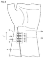
- FIG. 3 is a diagram showing a planar layout of impedance measurement electrodes constituting the first pulse wave sensor and the second pulse wave sensor in a state in which the sphygmomanometer according to the first embodiment is attached to the left wrist. .
- the electrode group 40E of the impedance measuring unit 40 corresponds to the radial artery 91 of the left wrist 90 along the longitudinal direction of the wrist (corresponding to the width direction Y of the belt 20). line up.
- the electrode group 40E includes current electrode pairs 41 and 46 (a pair of current application electrodes) for current conduction disposed on both sides in the width direction Y, and first detection electrode pairs 42 and 43 constituting a first pulse wave sensor 401. (A pair of voltage measurement electrodes) and a second detection electrode pair 44, 45 (another pair of voltage measurement electrodes) constituting the second pulse wave sensor 402 are included.
- the first pulse wave sensor 401 and the second pulse wave sensor 402 are disposed between the current electrode pair 41, 46.
- Each of the first detection electrode pair 42, 43 and the second detection electrode pair 44, 45 is an electrode for voltage measurement.
- the second detection electrode pair 44, 45 is disposed downstream of the first detection electrode pair 42, 43 in the blood flow direction of the radial artery 91.
- a distance D (see FIG. 5A) between the center of the first detection electrode pair 42, 43 and the center of the second detection electrode pair 44, 45 is, for example, about 20 mm.
- the distance D corresponds to a substantial distance between the first pulse wave sensor 401 and the second pulse wave sensor 402.
- the distance between the first detection electrode pair 42, 43 and the distance between the second detection electrode pair 44, 45 are both about 2 mm, for example.
- Such an electrode group 40E can be configured to be flat. Therefore, in the sphygmomanometer 1, the belt 20 can be configured to be thin as a whole. In addition, the electrode group 40E can be configured to have flexibility. For this reason, the electrode group 40E does not prevent the compression of the left wrist 90 by the compression cuff 21 and does not impair the accuracy of blood pressure measurement by the oscillometric method described later.
- FIG. 4 is a block diagram showing a control configuration of the sphygmomanometer according to the first embodiment.
- the control configuration of the sphygmomanometer 1 will be described with reference to FIG.
- the main unit 10 of the sphygmomanometer 1 includes a CPU 100 as a control unit, a memory 51 as a storage unit, and a communication unit 59 in addition to the display 50 and the operation unit 52 described above.
- a first pressure sensor 31 As a fluid supply source, a valve 33, and a second pressure sensor 34 are mounted.
- an oscillation circuit 310 and an oscillation circuit 340 that convert outputs from the first pressure sensor 31 and the second pressure sensor 34 into frequencies, and a pump drive circuit 320 that drives the pump 32 are mounted on the main body 10. ing.
- the conduction and voltage detection circuit 49 is mounted on the impedance measurement unit 40.
- a switching valve 35 is mounted which switches the connection destination of the pump 32 and the valve 33 to the compression cuff 21 or the pressure cuff 24.
- Display 50 is configured of, for example, an organic EL display.
- the display 50 displays information related to blood pressure measurement such as a blood pressure measurement result and other information in accordance with a control signal from the CPU 100.
- the display 50 is not limited to the organic EL display, and may be configured of, for example, another type of display such as a liquid crystal display.
- the operation unit 52 is formed of, for example, a push-type switch, and inputs an operation signal to the CPU 100 according to the user's instruction to start or stop blood pressure measurement.
- the operation unit 52 is not limited to a push switch, and may be, for example, a pressure-sensitive (resistive) or proximity (electrostatic capacitive) touch panel switch.
- a microphone (not shown) may be provided to input a blood pressure measurement start instruction by the user's voice.
- the memory 51 is data of a program for controlling the sphygmomanometer 1, data used to control the sphygmomanometer 1, setting data for setting various functions of the sphygmomanometer 1, data of measurement results of blood pressure values, etc. Is stored temporarily.
- the memory 51 is also used as a work memory or the like when a program is executed.
- the CPU 100 executes various functions as a control unit in accordance with a program for controlling the sphygmomanometer 1 stored in the memory 51. For example, when performing blood pressure measurement by the oscillometric method, the CPU 100 responds to the instruction to start blood pressure measurement from the operation unit 52, based on the signal from the first pressure sensor 31, the pump 32 (and the valve 33). Drive). Further, CPU 100 calculates a blood pressure value based on, for example, a signal from first pressure sensor 31.
- the CPU 100 drives the valve 33 to discharge the air in the compression cuff 21 according to the instruction to start the blood pressure measurement from the operation unit 52 Do. Further, the CPU 100 drives the switching valve 35 to switch the connection destination of the pump 32 (and the valve 33) to the pressure cuff 24. Furthermore, the CPU 100 calculates the blood pressure value based on the signal from the second pressure sensor 34.
- the communication unit 59 is controlled by the CPU 100 to transmit predetermined information to an external device via the network 900, receives information from an external device via the network 900, and delivers the information to the CPU 100.
- Communication via the network 900 may be either wireless or wired.
- the network 900 is the Internet (registered trademark), but is not limited to this, and may be another network such as an in-hospital LAN, or one-to-one using a USB cable or the like. It may be communication.
- the communication unit 59 may include a USB connect.
- the pump 32 and the valve 33 are connected to the compression cuff 21 and the pressure cuff 24 via the switching valve 35 and the air pipes 39a and 39b.
- the first pressure sensor 31 is connected to the compression cuff 21 via the air pipe 38a.
- the first pressure sensor 31 detects the pressure in the compression cuff 21.
- the second pressure sensor 34 is connected to the pressure cuff 24 via the air pipe 38 b.
- the second pressure sensor 34 detects the pressure in the pressure cuff 24.
- the switching valve 35 is driven based on a control signal supplied from the CPU 100 and switches the connection destination of the pump 32 and the valve 33 to the compression cuff 21 or the pressing cuff 24.
- Pump 32 is formed of, for example, a piezoelectric pump.
- the pump 32 supplies the air as the pressurizing fluid into the compression cuff 21 through the air pipe 39a. Thereby, the inside of the compression cuff 21 is pressurized.
- the pump 32 supplies the air as the pressurizing fluid into the pressure cuff 24 through the air pipe 39b. As a result, the inside of the pressure cuff 24 is pressurized.
- the valve 33 is mounted on the pump 32, and is configured to be controlled to open / close as the pump 32 is turned on / off.
- the valve 33 When the connection destination of the pump 32 and the valve 33 is switched to the compression cuff 21 by the switching valve 35, the valve 33 is closed when the pump 32 is turned on. Thus, air is supplied into the compression cuff 21. Meanwhile, the valve 33 opens when the pump 32 is turned off. Thereby, the air in the compression cuff 21 is exhausted to the atmosphere through the air pipe 39a.
- the valve 33 When the connection destination of the pump 32 and the valve 33 is switched to the pressure cuff 24 by the switching valve 35, the valve 33 is closed when the pump 32 is turned on. Thus, air is supplied into the pressure cuff 24. Meanwhile, the valve 33 opens when the pump 32 is turned off. As a result, the air in the pressure cuff 24 is discharged to the atmosphere through the air pipe 39b.
- the valve 33 has a function of a non-return valve so that the discharged air does not flow back.
- Pump drive circuit 320 drives pump 32 based on a control signal supplied from CPU 100.
- a piezoresistive pressure sensor can be employed as the first pressure sensor 31.
- the first pressure sensor 31 is connected to the pump 32, the valve 33 and the compression cuff 21 via the air pipe 38a.
- the first pressure sensor 31 detects the pressure of the belt 20 (compression cuff 21) via the air pipe 38a and outputs it as a time-series signal. The pressure is detected with reference to the atmospheric pressure (zero).
- the oscillation circuit 310 oscillates based on an electrical signal value based on a change in electrical resistance due to the piezoresistive effect from the first pressure sensor 31. Thereby, the oscillation circuit 310 outputs a frequency signal having a frequency corresponding to the electric signal value of the first pressure sensor 31 to the CPU 100.
- the output of the first pressure sensor 31 is used to control the pressure of the compression cuff 21 and to calculate a blood pressure value (including systolic blood pressure and diastolic blood pressure) by oscillometric method.
- the following operation is generally performed.
- the cuff is previously wrapped around the subject's measurement site (arm, etc.), and at the time of measurement, the CPU 100 controls the pump 32 and the valve 33 to pressurize the cuff pressure higher than the systolic blood pressure and gradually reduce the pressure thereafter.
- the cuff pressure is detected by a pressure sensor, and fluctuations in arterial volume generated in the artery at the measurement site are extracted as a pulse wave signal.
- the systolic blood pressure (systolic blood pressure) and the diastolic blood pressure (diastolic blood pressure) are calculated based on the change in the amplitude of the pulse wave signal (mainly rising and falling) accompanying the change in cuff pressure at that time.
- a piezoresistive pressure sensor can be employed as the second pressure sensor 34.
- the second pressure sensor 34 is connected to the pump 32, the valve 33 and the pressing cuff 24 via an air pipe 38 b.
- the second pressure sensor 34 detects the pressure of the pressure cuff 24 via the air pipe 38 b and outputs it as a time-series signal. The pressure is detected with reference to the atmospheric pressure (zero).
- the oscillation circuit 340 oscillates based on the electrical signal value based on the change in electrical resistance from the second pressure sensor 34 due to the piezoresistive effect. Thereby, the oscillation circuit 340 outputs a frequency signal having a frequency according to the electric signal value of the second pressure sensor 34 to the CPU 100.
- the output of the second pressure sensor 34 is used to control the pressure of the pressure cuff 24 and to calculate the blood pressure based on the pulse wave propagation time.
- the CPU 100 controls the pump 32 and the valve 33 to increase and decrease the cuff pressure according to various conditions. Do.
- the battery 53 is an element mounted on the main body 10, and in the present embodiment, the CPU 100, the first pressure sensor 31, the pump 32, the valve 33, the display 50, the memory 51, the communication unit 59, the oscillation circuit 310, and the pump drive Power is supplied to each element of the circuit 320.
- the battery 53 also supplies power to the energization and voltage detection circuit 49 of the impedance measurement unit 40 through the wiring 71.
- the wire 71 is placed between the main body 10 and the impedance measuring unit 40 along the circumferential direction of the belt 20 in a state of being sandwiched between the strip 23 of the belt 20 and the compression cuff 21 together with the wire 72 for signal. It is provided extending.
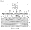
- FIG. 5A is a view schematically showing a cross section along the longitudinal direction of the wrist when performing blood pressure measurement based on pulse wave propagation time in a state where the sphygmomanometer according to Embodiment 1 is attached to the left wrist is there.
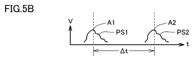
- FIG. 5B is a view showing waveforms of a first pulse wave signal and a second pulse wave signal respectively output by the first pulse wave sensor and the second pulse wave sensor in the blood pressure measurement in FIG. 5A.
- the energization and voltage detection circuit 49 of the impedance measurement unit 40 is controlled by the CPU 100.
- the CPU 100 causes the high frequency constant current i to flow between the current electrode pairs 41 and 46 disposed on both sides in the longitudinal direction of the wrist (the width direction Y of the belt 20).
- the high frequency constant current i is a current having a frequency of 50 kHz and a current value of 1 mA.
- the energization and voltage detection circuit 49 With the high frequency constant current i flowing between the current electrode pair 41, 46, the energization and voltage detection circuit 49 generates a voltage signal v1 between the first detection electrode pair 42, 43 that constitutes the first pulse wave sensor 401. , And detects a voltage signal v2 between the second detection electrode pair 44, 45 constituting the second pulse wave sensor 402.
- These voltage signals v1 and v2 are electric impedance by the pulse wave of the blood flow of the radial artery 91 in the portion of the palm side 90a of the left wrist 90 to which the first pulse wave sensor 401 and the second pulse wave sensor 402 oppose. Represents the change of (impedance method).
- the energizing and voltage detection circuit 49 rectifies, amplifies and filters these voltages v1 and v2 to generate a first pulse wave signal PS1 and a second pulse wave signal PS2 having a mountain-like waveform as shown in FIG. 5B. Output in time series.
- the voltage signals v1 and v2 are approximately 1 mV.
- the peaks A1 and A2 of the first pulse wave signal PS1 and the second pulse wave signal PS2 are, for example, 1V.
- the pulse wave velocity (PWV) of the blood flow of the radial artery 91 is in the range of 100 cm / s to 2000 cm / s
- a substantial difference between the first pulse wave sensor 401 and the second pulse wave sensor 402 is obtained. Since the interval D1 is 20 mm, the time difference ⁇ t between the first pulse wave signal SP1 and the second pulse wave signal SP2 is in the range of 1.0 ms to 2.0 ms.
- the pressure cuff 24 is in a pressurized state, and the pressure cuff 21 is in a non-pressurized state by discharging the internal air.
- the pressure cuff 24 is disposed to overlap the first pulse wave sensor 401, the second pulse wave sensor 402, and the current electrode pair 41, 46 in the thickness direction of the belt 20.
- the pressure cuff 24 presses the first pulse wave sensor 401, the second pulse wave sensor 402, and the current electrode pair 41, 46 against the palm side 90 a of the left wrist 90 when pressurized by the pump 32.
- the pressing forces of the current electrode pairs 41 and 46, the first pulse wave sensor 401, and the second pulse wave sensor 402 on the palm side 90a of the left wrist 90 can be set as appropriate.
- the pump 32 and the valve 33 can be used in common with the pressing cuff 21, and the configuration can be simplified. Further, as described later, since the first pulse wave sensor 401, the second pulse wave sensor 402, and the current electrode pairs 41 and 46 can be properly adhered to the body surface, the pressing force on the measurement site is substantially uniform. become. Thereby, the blood pressure measurement based on the pulse wave propagation time can be performed accurately.
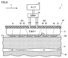
- FIG. 6 is a view schematically showing a cross section taken along the longitudinal direction of the wrist when blood pressure measurement is performed by the oscillometric method in a state where the sphygmomanometer according to the first embodiment is attached to the left wrist.
- the pressure cuff 24 is in a non-pressurized state by discharging air therein, and the compression cuff 21 is in a state where air is supplied.
- the compression cuff 21 extends in the circumferential direction of the left wrist 90, and when pressed by the pump 32, uniformly compresses the circumferential direction of the left wrist 90.
- only the flat pulse wave measurement electrode unit 200 exists between the inner circumferential surface 21 a of the compression cuff 21 and the left wrist 90. Therefore, the blood pressure can be sufficiently closed without the compression by the compression cuff 21 being inhibited by the other members. Therefore, blood pressure measurement by the oscillometric method can be performed with high accuracy.
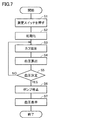
- FIG. 7 is a diagram showing an operation flow when the blood pressure monitor according to the first embodiment performs blood pressure measurement by the oscillometric method.
- step S1 When blood pressure measurement is performed by the oscillometric method, when the user instructs blood pressure measurement by the oscillometric method by the push-type switch as the operation unit 52 provided on the main body 10 (step S1), the CPU 100 starts operation And initialize the processing memory area (step S2). Further, the CPU 100 turns off the pump 32 via the pump drive circuit 320, opens the valve 33, and exhausts the air in the compression cuff 21. Subsequently, the current output value of the first pressure sensor 31 is set as a value corresponding to the atmospheric pressure (0 mmHg adjustment).
- the CPU 100 closes the valve 33 and then drives the pump 32 by the pump drive circuit 320 to supply air to the compression cuff 21.
- the compression cuff 21 is inflated and the cuff pressure is gradually increased (step S3).
- the CPU 100 monitors the cuff pressure by the first pressure sensor 31 in order to calculate the blood pressure value, whereby an arterial volume generated in the radial artery 91 of the left wrist 90 as the measurement site is obtained.
- the fluctuation component is acquired as a pulse wave signal.
- the CPU 100 functions as a second blood pressure calculation unit, and based on the pulse wave signal acquired at this time, a known algorithm by oscillometric method is applied to the blood pressure value (systolic blood pressure and diastolic period Try to calculate the blood pressure).
- step S5 when the blood pressure value can not be calculated because of insufficient data (step S5: NO), the processing of steps S3 to S5 is repeated as long as the cuff pressure has not reached the upper limit pressure.
- the upper limit pressure is determined in advance as, for example, 300 mmHg for safety.
- step S5 when the blood pressure value can be calculated (step S5: YES), the CPU 100 stops the pump 32 via the pump drive circuit 320, opens the valve 33, and discharges the air in the compression cuff 21. (Step S6). Finally, the measurement result of the blood pressure value is displayed on the display 50 and recorded in the memory 51 (step S7).
- the calculation of the blood pressure value is not limited to the pressurization process as described above, but may be performed in the depressurization process.
- FIG. 8 is a diagram showing an operation flow when the sphygmomanometer according to the first embodiment acquires a pulse wave propagation time and performs blood pressure measurement (estimation) based on the pulse wave propagation time (PTT).
- PTT pulse wave propagation time
- step S10 when performing blood pressure measurement (estimation) based on pulse wave propagation time, the user instructs blood pressure measurement based on PTT by a push-type switch as the operation unit 52 provided on the main body 10 Then (step S10), the CPU 100 drives the switching valve 35 to switch the connection destination of the pump 32 and the valve 33 to the pressure cuff 24 (step S11). Next, the CPU 100 closes the valve 33 and drives the pump 32 by the pump drive circuit 320 to supply air to the pressure cuff 24. As a result, the pressure cuff 24 is inflated and the cuff pressure is gradually increased (step S12). For example, the cuff pressure is continuously increased at a constant speed of about 5 mmHg / s. The cuff pressure may be increased stepwise in order to easily secure the time for calculating the cross-correlation coefficient r described later.
- the CPU 100 functions as a cross correlation coefficient calculation unit, and the first pulse wave signal PS1 and the second pulse wave which the first pulse wave sensor 401 and the second pulse wave sensor 402 respectively output in time series
- the signal PS2 is acquired, and the cross-correlation coefficient r between the waveforms of the first pulse wave signal PS1 and the second pulse wave signal PS2 is calculated in real time (step S13).
- the CPU 100 also functions as a pressing force setting unit, and determines whether the calculated cross-correlation coefficient r exceeds a predetermined threshold value Th (step 14).
- the threshold Th is 0.99.
- step S14 if the cross correlation coefficient r is less than or equal to the threshold Th (step S14: NO), the processing of steps S12 to S14 is repeated until the cross correlation coefficient r exceeds the threshold Th.
- step S14: YES when the cross correlation coefficient r exceeds the threshold value Th (step S14: YES), the CPU 100 stops the pump 32 (step S15), and the cuff pressure is at that time, that is, the cross correlation coefficient r is It is set to the value at the time of exceeding the threshold Th.
- the CPU 100 acquires a time difference ⁇ t (see FIG. 5B) between the first pulse wave signal PS1 and the second pulse wave signal PS2 as a pulse wave propagation time PTT (step S16). Specifically, a time difference ⁇ t between the peak A1 of the first pulse wave signal PS1 and the peak A2 of the second pulse wave signal PS2 in FIG. 5B is acquired as a pulse wave propagation time.
- the pulse wave propagation time By acquiring the pulse wave propagation time as described above, the measurement accuracy of the pulse wave propagation time can be enhanced. Further, since the cuff pressure is set to a value when the cross correlation coefficient r exceeds the threshold value Th, the pulse wave propagation time can be acquired without unnecessarily increasing the cuff pressure. This can reduce the physical burden on the user.
- the CPU 100 functions as a first blood pressure calculation unit, and based on the pulse wave propagation time acquired in step S16, using a predetermined correspondence equation between the pulse wave propagation time and the blood pressure.
- the blood pressure is calculated (estimated) (step S17).
- the blood pressure measurement accuracy can be enhanced.
- the measurement result of the blood pressure value is displayed on the display 50 and recorded in the memory 51.
- step S18 if measurement stop is not instructed by the operation unit 52 in step S18 (step S18: NO), the pulse wave propagation time is calculated (step S16) and the blood pressure is calculated (step S17). And periodically repeated each time the first pulse wave signal PS1 and the second pulse wave signal PS2 are input according to the pulse wave.
- the CPU 100 updates and displays the measurement result of the blood pressure value on the display 50, and accumulates and records it in the memory 51.
- step S18 step S18: YES
- blood pressure can be measured continuously over a long period of time with a physical burden on the user lightened by blood pressure measurement based on pulse wave propagation time.
- blood pressure measurement (estimate) based on pulse wave propagation time and blood pressure measurement by oscillometric method can be performed by an integrated device. Thereby, the convenience of the user can be enhanced.
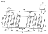
- FIG. 9 is a perspective view showing the pulse wave measurement electrode unit according to the first embodiment. The detailed configuration of the pulse wave measurement electrode unit 200 according to the first embodiment will be described with reference to FIG.
- the pulse wave measurement electrode unit 200 includes a plurality of electrodes 41 to 46, a support member 210, and a pressure cuff 24.
- the plurality of electrodes 41 to 46 are in contact with the body surface of the subject during measurement.
- the plurality of electrodes 41 to 46 have a plate-like shape.
- the plurality of electrodes 41 to 46 are arranged side by side along the width direction W of the support member 210 described later.
- Each of the plurality of electrodes 41 to 46 is provided on the surface of a divided bag 241 to 246 described later.
- the plurality of electrodes 41 to 46 are formed by printing or the like.
- the electrodes 41 and 46 correspond to a pair of current application electrodes.
- the electrodes 42 and 43 correspond to a first pair of voltage measurement electrodes.
- the electrodes 44 and 45 correspond to a second pair of voltage measurement electrodes. The first pair of voltage measurement electrodes and the second pair of voltage measurement electrodes are disposed between the pair of current application electrodes.
- the support member 210 has a sheet-like shape.
- the support member 210 has a first main surface 211 and a second main surface 212 opposed in the thickness direction.
- the first main surface 211 faces the body surface of the measurement subject in a mounted state in which the sphygmomanometer 1 (electrode unit for pulse wave measurement) is mounted on the measurement subject.
- the second major surface 212 is a surface on the opposite side of the first major surface 211 in the thickness direction of the support member 210.
- the support member 210 In the mounted state, the support member 210 has a length direction L which is a circumferential direction, and a width direction W orthogonal to the length direction L and the thickness direction.
- the support member 210 is made of, for example, an insulating resin member.
- the support member 210 preferably has flexibility but is configured not to be plastically deformed when pressed by the compression cuff 21 or the like.
- the pressing cuff 24 is configured to be able to expand and contract by taking in and out the fluid, and the plurality of electrodes 41 to 46 are pressed against the body surface of the person to be measured by expanding upon measurement.
- the pressure cuff 24 is provided on the first major surface 211.
- the pressure cuff 24 has a plurality of divided bags 241-246.
- Each of the plurality of divided bags 241 to 246 is disposed between the plurality of electrodes 41 to 46 and the first major surface 211 of the support member 210.
- the plurality of divided bags 241 to 246 are arranged side by side along the width direction W of the support member 210.
- the plurality of divided bags 241 to 246 are connected to the pump 32 by an air pipe 39a.
- One end of the air pipe 39a is connected to the pump 32, and the other end of the air pipe 39a is branched and connected to the plurality of divided bags 241 to 246.
- connection destinations of the pump 32 and the valve 33 are switched to the pressure cuff 24 by the switching valve 35 (see FIG. 4), and the pump 32 is driven in a state where the valve 33 is closed. Fluid is supplied to each of ⁇ 246. Thereby, each of the plurality of divided bags 241 to 246 is inflated. With the pump 32 stopped, by opening the valve 33, the air in the plurality of divided bags 241 to 246 is discharged to the outside.
- low rigidity portions R2 whose rigidity is lower than the portions R1 overlapping the electrodes in the thickness direction are provided between the adjacent electrodes.
- the low rigidity of the low rigidity portion R2 is provided by the formation of a gap between adjacent divided bags.
- the support member 210 and the divided bags 241 to 246 are stacked in the thickness direction.
- a gap is formed between the divided bags adjacent to each other, and only the support member 210 is disposed in this portion.
- the freedom of movement of each of the electrodes 41 to 46 is high. Become. Thus, even if the body surface is uneven, the electrodes 41 to 46 can be properly adhered to the body surface. As a result, detection accuracy of biological information can be improved.
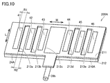
- FIG. 10 is a perspective view showing an electrode unit for pulse wave measurement according to the second embodiment.
- the pulse wave measurement electrode unit 200A according to the second embodiment will be described with reference to FIG.
- the supporting member 210A is different from the supporting member 210 according to the first embodiment in that a plurality of openings 213a to 213e are provided.
- the other configurations are almost the same.
- the plurality of openings 213a to 213e are provided between the adjacent electrodes.
- the opening 213 a is provided between the electrode 41 and the electrode 42.
- the opening 213 b is provided between the electrode 42 and the electrode 43.
- the opening 213 c is provided between the electrode 43 and the electrode 44.
- the opening 213 d is provided between the electrode 44 and the electrode 45.
- the opening 213 e is provided between the electrode 45 and the electrode 46.
- the electrodes 41 to 46 are provided on the first major surface 211 of the support member 210A.
- the electrodes 41 to 46 are formed on the first major surface 211 by a printing method, an evaporation method, a photolithography method, or the like.
- the pressing cuff 24A is disposed on the second main surface 212 side of the support member 210A.
- the pressing cuff 24A is disposed to overlap the entire support member 210A when viewed along the direction in which the support member 210A and the pressing cuff 24A are aligned.
- the pulse wave measurement electrode unit 200A is viewed from the first main surface 211 side along the direction in which the support member 210A and the pressing cuff 24A are arranged, the pressing cuff 24A is exposed from the openings 213a to 213e.
- low rigidity portions R2 whose rigidity is lower than the portions R1 overlapping the electrodes in the thickness direction are provided between the adjacent electrodes.
- the low rigidity of the low rigidity portion R2 is provided by providing the openings 213a to 213e in the support member 210A of the portions positioned between the adjacent electrodes.
- the support member 210A and the pressing cuff 24A are stacked in the thickness direction.
- an opening is formed in the support member 210A, and only the pressing cuff 24A is disposed in that portion.
- the openings 213a to 213e compared with the case where the openings 213a to 213e are not provided, a portion between the electrodes adjacent to each other and located around the openings 213a to 213e The rigidity of the support member 210A also decreases.
- the pulse wave measurement electrode unit 200A according to the second embodiment can obtain substantially the same effect as the pulse wave measurement electrode unit 200 according to the first embodiment.
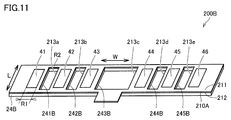
- FIG. 11 is a perspective view showing an electrode unit for pulse wave measurement according to the third embodiment.
- the pulse wave measurement electrode unit 200B according to the third embodiment will be described with reference to FIG.
- the pulse wave measurement electrode unit 200B according to the third embodiment differs from the pulse wave measurement electrode unit 200A according to the second embodiment in the configuration of the pressure cuff 24B.
- the other configurations are almost the same.
- portions corresponding to the openings 213a to 213e provided in the support member 210A are openings 241B to 245B.
- the pulse wave measurement electrode unit 200B in the portions located around the openings 213a to 213e and the openings 241B to 245B serves as the low rigidity portion R2.
- the low rigidity of the low rigidity portion R2 is provided by the openings 213a to 213e and the openings 241B to 245B.
- the openings 213a to 213e in the support member 210A are positioned between the adjacent electrodes and around the openings 213a to 213e as compared with the case where the openings 213a to 213e are not provided.
- the rigidity of the portion of the support member 210A is reduced.
- the pulse wave measurement electrode unit 200B according to Embodiment 3 can obtain substantially the same effect as the pulse wave measurement electrode unit 200 according to Embodiment 2.
- FIG. 12 is a perspective view showing an electrode unit for pulse wave measurement according to the fourth embodiment.
- the pulse wave measurement electrode unit 200C according to the fourth embodiment will be described with reference to FIG.
- the pulse wave measurement electrode unit 200C according to the fourth embodiment has a configuration of the support member 210C and the pressing cuff 24C when compared with the pulse wave measurement electrode unit 200B according to the third embodiment. Is different. The other configurations are almost the same.
- the supporting member 210C is different from the supporting member 210A according to the third embodiment in that a plurality of cutouts 214a to 214e are provided instead of the plurality of openings 213a to 213e.
- the other configurations are almost the same.
- the plurality of notches 214a to 214e are provided between the adjacent electrodes.
- the plurality of cutouts 214a to 214e are provided to open at one end side in the length direction L of the support member 210A.
- the plurality of cutouts 214a to 214e may be provided so as to open on the other end side in the longitudinal direction L of the support member 210A, and one end side and the other end in the longitudinal direction L of the support member 210A. It may be provided to open alternately on the side.
- the portions of the pressing cuff 24B corresponding to the notches 214a to 214e provided in the support member 210A are notches 241C to 245C.
- the pulse wave measurement electrode unit 200C in the portions located around the notches 214a to 214e and the notches 241C to 245C is the low rigidity portion R2.
- the low rigidity of the low rigidity portion R2 is provided by providing the notches 214a to 214e and the notches 241C to 245C.
- the notches 214a to 214e in the support member 210C are positioned between the adjacent electrodes and around the notches 214a to 214e as compared with the case where the notches 214a to 214e are not provided.
- the rigidity of the portion of the support member 210C is reduced.
- the pulse wave measurement electrode unit 200C according to Embodiment 4 can obtain substantially the same effect as the pulse wave measurement electrode unit 200B according to Embodiment 3.
- the present invention is not limited thereto, and the cutaway portions 241C to 245C may not be provided.
- the low rigidity of the low rigidity portion R2 provided between the adjacent electrodes is obtained by providing the notches 214a to 214e in the support members 210A of the portions positioned between the adjacent electrodes. It is brought about by
- the configuration exemplified as the above-described embodiment is an example of the configuration of the present disclosure, and can be combined with another known technique. It is also possible to change and configure.
- the pulse wave measurement electrode unit is described as being mounted on the wrist type sphygmomanometer configured to be attachable to the wrist of the person to be measured. It is not limited. For example, it may be mounted on a sphygmomanometer attached to a part other than the wrist.
- the pulse wave measurement electrode unit may be incorporated into the belt 20 from which the compression cuff 21 is omitted from the sphygmomanometer 1 described above.
- the pulse wave measurement device has no blood pressure measurement function, and functions as a blood pressure estimation device that estimates the blood pressure from the detected pulse wave information.
- the pressure cuff of the pulse wave measurement electrode unit is provided independently of the compression cuff of the sphygmomanometer 1, the present invention is not limited thereto. May consist of a cuff common to the compression cuff and may be used as part of the compression cuff. In this case, the compression cuff functions as a fluid bag.
- SYMBOLS 1 sphygmomanometer 10 body, 10b bottom surface, 15 buckle, 20 belt, 20a inner peripheral surface, 20b outer peripheral surface, 20e, 20f end, 21 compression cuff, 21a inner peripheral surface, 23 bands, 23a inner peripheral surface, 24 , 24A, 24B, 24C pressing cuffs, 25 first plate material, 25e, 25f end, 26 second plate material, 26e, 26f end, 27, 28 connecting rod, 29 fixing portion, 31 first Pressure sensor, 32 pumps, 33 valves, 34 second pressure sensors, 35 switching valves, 38a, 38b, 39a, 39b Air piping, 40 impedance measuring unit, 40E electrode group, 41, 42, 43, 44, 45, 46 electrodes , 49 energization and voltage detection circuits, 50 displays, 51 memories, 52 operation units, 53 batteries, 59 communication units, 71, 72 , 90 left wrist, 90a palmar side, 91 radial artery, 200, 200A, 200B, 200C pulse wave measurement
Landscapes
- Health & Medical Sciences (AREA)
- Life Sciences & Earth Sciences (AREA)
- Engineering & Computer Science (AREA)
- Surgery (AREA)
- General Health & Medical Sciences (AREA)
- Biophysics (AREA)
- Biomedical Technology (AREA)
- Heart & Thoracic Surgery (AREA)
- Medical Informatics (AREA)
- Molecular Biology (AREA)
- Physics & Mathematics (AREA)
- Animal Behavior & Ethology (AREA)
- Pathology (AREA)
- Public Health (AREA)
- Veterinary Medicine (AREA)
- Cardiology (AREA)
- Physiology (AREA)
- Signal Processing (AREA)
- Measuring Pulse, Heart Rate, Blood Pressure Or Blood Flow (AREA)
- Measurement And Recording Of Electrical Phenomena And Electrical Characteristics Of The Living Body (AREA)
Priority Applications (3)
| Application Number | Priority Date | Filing Date | Title |
|---|---|---|---|
| DE112018004120.4T DE112018004120T5 (de) | 2017-09-14 | 2018-08-17 | Pulswellenmesselektrodeneinheit und pulswellenmessvorrichtung |
| CN201880058355.2A CN111065322A (zh) | 2017-09-14 | 2018-08-17 | 脉波测定用电极单元以及脉波测定装置 |
| US16/814,172 US11457828B2 (en) | 2017-09-14 | 2020-03-10 | Pulse wave measurement electrode unit and pulse wave measurement device |
Applications Claiming Priority (2)
| Application Number | Priority Date | Filing Date | Title |
|---|---|---|---|
| JP2017176931A JP6869152B2 (ja) | 2017-09-14 | 2017-09-14 | 脈波測定用電極ユニットおよび脈波測定装置 |
| JP2017-176931 | 2017-09-14 |
Related Child Applications (1)
| Application Number | Title | Priority Date | Filing Date |
|---|---|---|---|
| US16/814,172 Continuation US11457828B2 (en) | 2017-09-14 | 2020-03-10 | Pulse wave measurement electrode unit and pulse wave measurement device |
Publications (1)
| Publication Number | Publication Date |
|---|---|
| WO2019054122A1 true WO2019054122A1 (ja) | 2019-03-21 |
Family
ID=65723611
Family Applications (1)
| Application Number | Title | Priority Date | Filing Date |
|---|---|---|---|
| PCT/JP2018/030525 WO2019054122A1 (ja) | 2017-09-14 | 2018-08-17 | 脈波測定用電極ユニットおよび脈波測定装置 |
Country Status (5)
| Country | Link |
|---|---|
| US (1) | US11457828B2 (zh) |
| JP (1) | JP6869152B2 (zh) |
| CN (1) | CN111065322A (zh) |
| DE (1) | DE112018004120T5 (zh) |
| WO (1) | WO2019054122A1 (zh) |
Cited By (1)
| Publication number | Priority date | Publication date | Assignee | Title |
|---|---|---|---|---|
| CN113274027A (zh) * | 2021-06-17 | 2021-08-20 | 复旦大学 | 一种在体多通道脑电信号记录装置 |
Families Citing this family (1)
| Publication number | Priority date | Publication date | Assignee | Title |
|---|---|---|---|---|
| CN111887832B (zh) * | 2020-07-28 | 2023-05-02 | 深圳市大富智慧健康科技有限公司 | 一种脉搏波测量袖带及脉搏波测量装置 |
Citations (4)
| Publication number | Priority date | Publication date | Assignee | Title |
|---|---|---|---|---|
| JP2003169779A (ja) * | 2001-12-06 | 2003-06-17 | Fukuda Denshi Co Ltd | 脈波伝播速度測定装置 |
| WO2007135895A1 (ja) * | 2006-05-24 | 2007-11-29 | Omron Corporation | アレイ型静電容量式センサ |
| JP2008136655A (ja) * | 2006-12-01 | 2008-06-19 | Omron Healthcare Co Ltd | 脈波測定用電極ユニットおよび脈波測定装置 |
| JP2008228995A (ja) * | 2007-03-20 | 2008-10-02 | Omron Healthcare Co Ltd | 体脂肪測定装置 |
Family Cites Families (26)
| Publication number | Priority date | Publication date | Assignee | Title |
|---|---|---|---|---|
| JP3671746B2 (ja) | 1999-06-11 | 2005-07-13 | 松下電工株式会社 | 血圧計 |
| JP2005005606A (ja) * | 2003-06-13 | 2005-01-06 | Tdk Corp | 巻線型電子部品の製造方法 |
| JP4423481B2 (ja) * | 2005-05-13 | 2010-03-03 | 誠次郎 富田 | 生体信号検出装置 |
| JP2007301232A (ja) * | 2006-05-12 | 2007-11-22 | Omron Healthcare Co Ltd | 圧脈波センサおよびこれを備えた脈波測定装置 |
| US20080021771A1 (en) | 2006-05-31 | 2008-01-24 | Ling Wu | Systems and methods for defining pricing conditions in electronic sales application environments |
| JP2008168054A (ja) * | 2007-01-15 | 2008-07-24 | Citizen Holdings Co Ltd | 手首装着型の生体測定装置用のバンド |
| US7800232B2 (en) * | 2007-03-06 | 2010-09-21 | Denso Corporation | Metallic electrode forming method and semiconductor device having metallic electrode |
| JP2008228989A (ja) * | 2007-03-20 | 2008-10-02 | Omron Healthcare Co Ltd | 生体インピーダンス測定用装着ユニット |
| JP2008295882A (ja) * | 2007-06-01 | 2008-12-11 | Omron Healthcare Co Ltd | 体脂肪測定装置 |
| JP4893515B2 (ja) * | 2007-07-19 | 2012-03-07 | オムロンヘルスケア株式会社 | 生体インピーダンス測定用胴部装着ユニットおよび体脂肪測定装置 |
| JP2009226167A (ja) | 2008-03-25 | 2009-10-08 | Toshiba Corp | 脈波計測装置及びこれを用いた自律神経解析システム |
| KR101198377B1 (ko) * | 2010-07-23 | 2012-11-07 | 주식회사 유메딕스 | 탈부착형 생체 신호 검측 패드 및 그것을 이용한 생체 신호 검측 장치 |
| JP5580801B2 (ja) * | 2011-10-13 | 2014-08-27 | セイコーインスツル株式会社 | 生体情報検出装置 |
| JP6381976B2 (ja) * | 2014-06-11 | 2018-08-29 | フクダ電子株式会社 | 生体情報測定装置、及び生体情報測定用カフ |
| US20170251934A1 (en) * | 2014-08-27 | 2017-09-07 | Nec Corporation | Pulse wave measurement device and blood pressure measurement device |
| WO2016040264A1 (en) * | 2014-09-08 | 2016-03-17 | Braintree Analytics Llc | Electrical coupling of pulse transit time (ptt) measurement system to heart for blood pressure measurment |
| US9781984B2 (en) * | 2015-03-08 | 2017-10-10 | Apple Inc. | Dynamic fit adjustment for wearable electronic devices |
| KR102420009B1 (ko) * | 2015-04-08 | 2022-07-12 | 삼성전자주식회사 | 생체 정보 측정 장치 |
| US11213212B2 (en) * | 2015-12-07 | 2022-01-04 | Samsung Electronics Co., Ltd. | Apparatus for measuring blood pressure, and method for measuring blood pressure by using same |
| EP3386388A4 (en) * | 2016-01-21 | 2019-08-14 | Plethy, Inc. | HEALTH MONITORING DEVICES, SYSTEMS AND METHODS WITH CIRCULAR CHANGES OF A BODY PART |
| JP6862093B2 (ja) * | 2016-03-16 | 2021-04-21 | フクダ電子株式会社 | 血圧脈波測定装置 |
| TWI584781B (zh) * | 2016-03-23 | 2017-06-01 | 美盛醫電股份有限公司 | 血壓量測裝置及血壓量測方法 |
| US20190209031A1 (en) * | 2016-09-05 | 2019-07-11 | Nec Corporation | Blood pressure measuring device, blood pressure measuring method and recording medium having blood pressure measuring program recorded therein |
| CN106580273A (zh) * | 2016-11-28 | 2017-04-26 | 中国科学院微电子研究所 | 脉搏波采集装置和脉搏波采集标定方法 |
| US20180206734A1 (en) * | 2017-01-20 | 2018-07-26 | Kentec Inc. | Wrist type apparatus for measurement of cardiovascular health, system, and method thereof |
| CN106963351B (zh) * | 2017-04-13 | 2019-11-01 | 清华-伯克利深圳学院筹备办公室 | 一种具有脉搏波检测系统的手环结构 |
-
2017
- 2017-09-14 JP JP2017176931A patent/JP6869152B2/ja active Active
-
2018
- 2018-08-17 DE DE112018004120.4T patent/DE112018004120T5/de active Pending
- 2018-08-17 WO PCT/JP2018/030525 patent/WO2019054122A1/ja active Application Filing
- 2018-08-17 CN CN201880058355.2A patent/CN111065322A/zh active Pending
-
2020
- 2020-03-10 US US16/814,172 patent/US11457828B2/en active Active
Patent Citations (4)
| Publication number | Priority date | Publication date | Assignee | Title |
|---|---|---|---|---|
| JP2003169779A (ja) * | 2001-12-06 | 2003-06-17 | Fukuda Denshi Co Ltd | 脈波伝播速度測定装置 |
| WO2007135895A1 (ja) * | 2006-05-24 | 2007-11-29 | Omron Corporation | アレイ型静電容量式センサ |
| JP2008136655A (ja) * | 2006-12-01 | 2008-06-19 | Omron Healthcare Co Ltd | 脈波測定用電極ユニットおよび脈波測定装置 |
| JP2008228995A (ja) * | 2007-03-20 | 2008-10-02 | Omron Healthcare Co Ltd | 体脂肪測定装置 |
Cited By (2)
| Publication number | Priority date | Publication date | Assignee | Title |
|---|---|---|---|---|
| CN113274027A (zh) * | 2021-06-17 | 2021-08-20 | 复旦大学 | 一种在体多通道脑电信号记录装置 |
| CN113274027B (zh) * | 2021-06-17 | 2022-07-05 | 复旦大学 | 一种在体多通道脑电信号记录装置 |
Also Published As
| Publication number | Publication date |
|---|---|
| US11457828B2 (en) | 2022-10-04 |
| US20200205683A1 (en) | 2020-07-02 |
| JP2019051009A (ja) | 2019-04-04 |
| JP6869152B2 (ja) | 2021-05-12 |
| CN111065322A (zh) | 2020-04-24 |
| DE112018004120T5 (de) | 2020-04-30 |
Similar Documents
| Publication | Publication Date | Title |
|---|---|---|
| US11622694B2 (en) | Pulse wave measurement device, pulse wave measurement method, and blood pressure measurement device | |
| JP6693274B2 (ja) | 血圧測定用カフおよび血圧計 | |
| JP6761337B2 (ja) | 脈波測定装置および脈波測定方法、並びに血圧測定装置 | |
| US11712166B2 (en) | Sphygmomanometer, and method and device for blood pressure measurement | |
| WO2019124025A1 (ja) | 測定装置およびプログラム | |
| WO2019054122A1 (ja) | 脈波測定用電極ユニットおよび脈波測定装置 | |
| JP2019050853A (ja) | 表示制御装置およびプログラム | |
| WO2019054118A1 (ja) | 血圧推定装置 | |
| US20190290142A1 (en) | Pulse wave measurement device, pulse wave measurement method, and blood pressure measurement device | |
| US20200205679A1 (en) | Health device flow path formation member, health device flow path formation unit, and health device | |
| US20200297224A1 (en) | Blood pressure estimation apparatus | |
| JP2009297222A (ja) | 血圧情報測定装置におけるカフ構造、および血圧情報測定装置 | |
| CN110891480B (zh) | 测定装置和测定方法 | |
| WO2019176530A1 (ja) | 生体情報測定装置 | |
| US11793414B2 (en) | Electrode unit, pulse wave measurement unit, and pulse wave measurement device |
Legal Events
| Date | Code | Title | Description |
|---|---|---|---|
| 121 | Ep: the epo has been informed by wipo that ep was designated in this application |
Ref document number: 18855620 Country of ref document: EP Kind code of ref document: A1 |
|
| 122 | Ep: pct application non-entry in european phase |
Ref document number: 18855620 Country of ref document: EP Kind code of ref document: A1 |