WO2019049801A1 - 対向ピストン型ディスクブレーキ用キャリパ - Google Patents
対向ピストン型ディスクブレーキ用キャリパ Download PDFInfo
- Publication number
- WO2019049801A1 WO2019049801A1 PCT/JP2018/032493 JP2018032493W WO2019049801A1 WO 2019049801 A1 WO2019049801 A1 WO 2019049801A1 JP 2018032493 W JP2018032493 W JP 2018032493W WO 2019049801 A1 WO2019049801 A1 WO 2019049801A1
- Authority
- WO
- WIPO (PCT)
- Prior art keywords
- cylinders
- caliper
- center
- piston type
- rotor
- Prior art date
Links
Images


Classifications
-
- F—MECHANICAL ENGINEERING; LIGHTING; HEATING; WEAPONS; BLASTING
- F16—ENGINEERING ELEMENTS AND UNITS; GENERAL MEASURES FOR PRODUCING AND MAINTAINING EFFECTIVE FUNCTIONING OF MACHINES OR INSTALLATIONS; THERMAL INSULATION IN GENERAL
- F16D—COUPLINGS FOR TRANSMITTING ROTATION; CLUTCHES; BRAKES
- F16D65/00—Parts or details
- F16D65/005—Components of axially engaging brakes not otherwise provided for
- F16D65/0068—Brake calipers
- F16D65/0075—Brake calipers assembled from a plurality of parts
-
- F—MECHANICAL ENGINEERING; LIGHTING; HEATING; WEAPONS; BLASTING
- F16—ENGINEERING ELEMENTS AND UNITS; GENERAL MEASURES FOR PRODUCING AND MAINTAINING EFFECTIVE FUNCTIONING OF MACHINES OR INSTALLATIONS; THERMAL INSULATION IN GENERAL
- F16D—COUPLINGS FOR TRANSMITTING ROTATION; CLUTCHES; BRAKES
- F16D55/00—Brakes with substantially-radial braking surfaces pressed together in axial direction, e.g. disc brakes
- F16D55/02—Brakes with substantially-radial braking surfaces pressed together in axial direction, e.g. disc brakes with axially-movable discs or pads pressed against axially-located rotating members
- F16D55/22—Brakes with substantially-radial braking surfaces pressed together in axial direction, e.g. disc brakes with axially-movable discs or pads pressed against axially-located rotating members by clamping an axially-located rotating disc between movable braking members, e.g. movable brake discs or brake pads
- F16D55/228—Brakes with substantially-radial braking surfaces pressed together in axial direction, e.g. disc brakes with axially-movable discs or pads pressed against axially-located rotating members by clamping an axially-located rotating disc between movable braking members, e.g. movable brake discs or brake pads with a separate actuating member for each side
-
- F—MECHANICAL ENGINEERING; LIGHTING; HEATING; WEAPONS; BLASTING
- F16—ENGINEERING ELEMENTS AND UNITS; GENERAL MEASURES FOR PRODUCING AND MAINTAINING EFFECTIVE FUNCTIONING OF MACHINES OR INSTALLATIONS; THERMAL INSULATION IN GENERAL
- F16D—COUPLINGS FOR TRANSMITTING ROTATION; CLUTCHES; BRAKES
- F16D65/00—Parts or details
- F16D65/02—Braking members; Mounting thereof
-
- F—MECHANICAL ENGINEERING; LIGHTING; HEATING; WEAPONS; BLASTING
- F16—ENGINEERING ELEMENTS AND UNITS; GENERAL MEASURES FOR PRODUCING AND MAINTAINING EFFECTIVE FUNCTIONING OF MACHINES OR INSTALLATIONS; THERMAL INSULATION IN GENERAL
- F16D—COUPLINGS FOR TRANSMITTING ROTATION; CLUTCHES; BRAKES
- F16D55/00—Brakes with substantially-radial braking surfaces pressed together in axial direction, e.g. disc brakes
- F16D2055/0004—Parts or details of disc brakes
- F16D2055/0016—Brake calipers
- F16D2055/002—Brake calipers assembled from a plurality of parts
-
- F—MECHANICAL ENGINEERING; LIGHTING; HEATING; WEAPONS; BLASTING
- F16—ENGINEERING ELEMENTS AND UNITS; GENERAL MEASURES FOR PRODUCING AND MAINTAINING EFFECTIVE FUNCTIONING OF MACHINES OR INSTALLATIONS; THERMAL INSULATION IN GENERAL
- F16D—COUPLINGS FOR TRANSMITTING ROTATION; CLUTCHES; BRAKES
- F16D2121/00—Type of actuator operation force
- F16D2121/02—Fluid pressure
- F16D2121/04—Fluid pressure acting on a piston-type actuator, e.g. for liquid pressure
-
- F—MECHANICAL ENGINEERING; LIGHTING; HEATING; WEAPONS; BLASTING
- F16—ENGINEERING ELEMENTS AND UNITS; GENERAL MEASURES FOR PRODUCING AND MAINTAINING EFFECTIVE FUNCTIONING OF MACHINES OR INSTALLATIONS; THERMAL INSULATION IN GENERAL
- F16D—COUPLINGS FOR TRANSMITTING ROTATION; CLUTCHES; BRAKES
- F16D65/00—Parts or details
- F16D65/14—Actuating mechanisms for brakes; Means for initiating operation at a predetermined position
- F16D65/16—Actuating mechanisms for brakes; Means for initiating operation at a predetermined position arranged in or on the brake
- F16D65/18—Actuating mechanisms for brakes; Means for initiating operation at a predetermined position arranged in or on the brake adapted for drawing members together, e.g. for disc brakes
- F16D65/183—Actuating mechanisms for brakes; Means for initiating operation at a predetermined position arranged in or on the brake adapted for drawing members together, e.g. for disc brakes with force-transmitting members arranged side by side acting on a spot type force-applying member
Definitions
- the present invention relates to a caliper constituting an opposed piston type disc brake used for braking a vehicle such as a car.
- Disc brakes are widely used to brake cars. At the time of braking by the disc brake, a pair of pads disposed on both sides in the axial direction of the rotor rotating with the wheel is pressed by the piston against the opposite axial sides of the rotor.
- various types of disc brakes have conventionally been known, but opposed piston type disc brakes in which pistons are disposed on both sides in the axial direction of the rotor so as to obtain stable braking force.
- use cases are increasing.
- FIG. 13 shows the caliper 1 for the opposed piston type disc brake of the conventional structure described in Japanese Patent Application Laid-Open No. 2013-29197.
- the caliper 1 is mounted on a high performance car such as a sports car, and has a pair of bodies 3 arranged on both sides in the axial direction of the rotor 2 respectively having five cylinders 4a to 4e.
- the centers of the three cylinders 4a to 4c arranged radially outward are located on the same imaginary circle ⁇ centered on the center of the rotor 2.
- the centers of the two cylinders 4 d and 4 e disposed radially inward are located on the same imaginary circle ⁇ centered on the center of the rotor 2.
- the two cylinders 4d and 4e disposed radially inward are positioned at the cylinder 4a located at the circumferential center and both sides of the cylinder 4a. Between the cylinders 4b and 4c.
- the present invention has been made in view of the above-described circumstances, and an object thereof is to suppress uneven wear of a pad with respect to a caliper for an opposed piston type disk brake having five cylinders in one pair of bodies. It is about realizing the structure.
- a caliper for opposed-piston disc brakes comprising a pair of bodies arranged on both sides of a rotor that rotates with the wheels, each having five cylinders, Of the five cylinders respectively provided in the pair of bodies, the center of the central cylinder surrounded by the four cylinders around the center is the most radially outward of the four cylinders centered on the center of the rotor.
- the cylinder disposed radially outward may be one cylinder, or may exist on the same imaginary circle (outside reference circle) centered on the center of the rotor.
- at least one cylinder is present radially outward of the central cylinder, and at least two cylinders are present radially inwardly of the central cylinder.
- at least one cylinder is present on one side in the circumferential direction and on the other side in the circumferential direction with respect to the central cylinder.
- a center bridge is provided on the radially outer side of the outer peripheral edge of the rotor to connect circumferential middle portions of the pair of bodies with each other, and the center bridge is provided with a bridge hole penetrating in the radial direction.
- An opposed piston type in which an imaginary plane intersecting with the bridge hole in an imaginary plane including the central axis of the rotor intersects with the central cylinder and the through hole respectively provided in the pair of bodies.
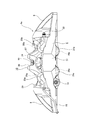
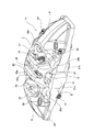
- FIG. 1 is a view of an opposed piston type disc brake according to a first example of an embodiment of the present invention as viewed from the outside in the axial direction.
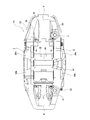
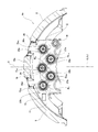
- FIG. 2 is a view of an opposed piston type disc brake according to a first example of the embodiment according to the present invention as viewed from the inside in the axial direction.
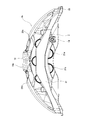
- FIG. 3 is a view of a facing piston type disc brake according to a first example of the embodiment according to the present invention as viewed from the outer side in the radial direction.
- FIG. 4 is a view of a facing piston type disc brake according to a first example of the embodiment according to the present invention as viewed from inside in the radial direction.
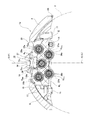
- FIG. 5 is a cross-sectional view taken along line AA of FIG. FIG.
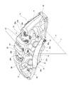
- FIG. 6 is a view showing a state in which the pad is assembled to FIG.
- FIG. 7 is a perspective view of the opposed piston type disk brake according to the first example of the embodiment according to the present invention as viewed from the radially outer side, the axially outer side and the turn-in side.
- FIG. 8 is a perspective view of the opposed piston type disc brake according to the first example of the embodiment according to the present invention as viewed from the radially outer side, the axially inner side and the turnout side.
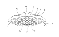
- FIG. 9 is a view of an opposed piston type disc brake according to a second example of the embodiment according to the present invention as viewed from the outside in the axial direction.
- FIG. 7 is a perspective view of the opposed piston type disk brake according to the first example of the embodiment according to the present invention as viewed from the radially outer side, the axially outer side and the turn-in side.
- FIG. 8 is a perspective view of the opposed piston type disc brake according to the first example of the embodiment according to the present invention as
- FIG. 10 is a view of an opposed piston type disc brake according to a second example of the embodiment according to the present invention as viewed from the inside in the axial direction.
- FIG. 11 is a view of a facing piston type disc brake according to a second example of the embodiment according to the present invention as viewed from the outside in the radial direction.
- FIG. 12 is a cross-sectional view taken along a line BB in FIG.
- FIG. 13 is a view of the conventional opposed-piston disc brake caliper as viewed from the outside in the axial direction.
- the opposed-piston disc brake of this embodiment is mounted on a high-performance car such as a sports car, and roughly includes a caliper 1a and a pair of pads 5 (inner pad and outer pad).
- the caliper 1a movably supports the pair of pads 5 in the axial direction (the front and back direction in FIG. 1, FIG. 2, FIG. 5 and FIG. 6, and the vertical direction in FIG. It is integrally formed by subjecting a light alloy or iron-based alloy material of the above to a casting process or the like.
- the caliper 1a is a pair of inner body 6 and outer body 7 disposed on both sides in the axial direction of the disc-shaped rotor 2 (see FIG. 5) rotating with the wheel, and circumferential direction of the inner body 6 and outer body 7 It includes a turn-in side connection portion 8 and a turn-out side connection portion 9 connecting both end portions, and a center bridge 10 connecting middle portions in the circumferential direction of the inner body 6 and the outer body 7.
- the caliper 1a has a substantially arcuate shape when viewed in the axial direction, and is supported and fixed to a vehicle body (knuckle of a suspension system) by using a pair of attaching portions 11 provided on the inner body 6.
- axial direction means “axial direction”, “radial direction” and “circumferential direction” of the rotor 2 unless otherwise specified.
- radially outside refers to the side farther from the center O r of the rotor 2
- radially inside refers to the side closer to the center O r of the rotor 2.
- the pad 5 is composed of a lining (friction material) 12 and a metal pressure plate (back plate) 13 supporting the back surface of the lining 12.
- the inner body 6 and the outer body 7 are provided with a pad pin 14 and a guide recessed groove 15 in order to support the pad 5 so as to be movable in the axial direction.
- pad pins 14 are supported (fixed) coaxially with each other at the radially inner end of one side (turn-in side) of the inner body 6 and the outer body 7 in the circumferential direction.
- Each pad pin 14 is inserted into a through hole 16 formed at the radially inner end of one circumferential end (turn-in end) of the pressure plate 13.
- the guide wall part 17 protruded in the axial direction is provided in the axial direction side which mutually opposes the circumferential direction other side (turning out side) part among the inner body 6 and the outer body 7.
- the guide recessed groove 15 provided in the guide wall portion 17 the ear portion 18 formed at the other end (turn-out end) of the pressure plate 13 in the circumferential direction is axially movably engaged There is.
- each of the inner body 6 and the outer body 7 is provided with one central cylinder 19, two outer diameter cylinders 20a and 20b, and two inner diameter cylinders 21a and 21b. Further, the openings of the five cylinders 19, 20a, 20b, 21a, 21b provided in the inner body 6 and the five cylinders 19, 20a, 20b, 21a, 21b provided in the outer body 7 are axial It is provided at symmetrical positions facing in the direction. In the present embodiment, the cylinder diameters of the five cylinders 19, 20a, 20b, 21a, 21b are the same.
- the central cylinder 19 is surrounded by four cylinders 20a, 20b, 21a, 21b (two outer cylinder 20a, 20b and two inner cylinders 21a, 21b).
- the central cylinder 19 has cylinders (two each in the illustrated example) on both sides in the circumferential direction and on both sides in the radial direction.
- the central cylinder 19 is provided at a circumferential direction intermediate portion and a radial direction intermediate portion of the inner body 6 and the outer body 7.
- the center O 19 of the central cylinder 19 is slightly offset to the other side (turning side) in the circumferential direction than an imaginary line C passing through the center O r of the rotor 2 and the circumferential center of the inner body 6 and the outer body 7 It is provided in the position.
- the outer diameter side cylinders 20a and 20b are two cylinders disposed radially outside among the four cylinders 20a, 20b, 21a and 21b, and are provided on radially outer portions of the inner body 6 and the outer body 7 It is done.
- the outer cylinders 20a and 20b are disposed radially outward of the central cylinder 19 and are disposed on both sides of the central cylinder 19 in the circumferential direction. Further, the centers O 20a and O 20b of the outer diameter side cylinders 20a and 20b respectively exist on the same imaginary circle centered on the center O r of the rotor 2.
- the cylinders disposed radially outward most are the two outer diameter side cylinders 20a, 20b, and these two outer diameter sides cylinder 20a, 20b of the center O 20a, the virtual circle passing through O 20b becomes the outer reference circle R O. Further, the outer diameter side cylinders 20a and 20b are disposed at positions symmetrical with respect to the imaginary line C.
- the inner diameter side cylinders 21a and 21b are two cylinders disposed radially inward among the four cylinders 20a, 20b, 21a and 21b, and provided at the radially inner end portions of the inner body 6 and the outer body 7 ing.
- the inner cylinders 21a and 21b are disposed radially inward of the central cylinder 19 and disposed on both sides of the central cylinder 19 in the circumferential direction.
- the inner diameter side cylinders 21a and 21b are not arranged in line symmetry with respect to the imaginary line C.
- the center O 19 of the central cylinder 19 passes radially between the outer reference circle R O and the centers O 21 a and O 21 b of the two inner cylinders 21 a and 21 b (centers connecting) present in the radially outward than the inner reference line R I, is located in a region denoted by the cross hatching pattern in FIG. That is, the center O 19 of the central cylinder 19, as in the conventional structure, most (two in this embodiment the outer diameter side cylinder 20a, 20b) radially located outside is a cylinder disposed on an imaginary circle passing through the center of the It is not located radially inward of this imaginary circle.
- two outer diameter side cylinders 20a and 20b, a central cylinder 19, and two inner diameter side cylinders 21a and 21b are provided in three stages in the radial direction.
- An oil passing hole (not shown) is formed in the inner body 6 and the outer body 7 in order to supply and discharge pressure oil to the back of five cylinders 19, 20a, 20b, 21a and 21b, respectively. It is opened at the back of 19, 20a, 20b, 21a, 21b. Further, among the both ends of the oil passing hole provided in each of the inner body 6 and the outer body 7, one end is closed by the bleeder screw 22, and the other end is communicated by the communication pipe 23. Further, on the axially inner side surface of the inner body 6 and the axially outer side surface of the outer body 7, a part of the outer shape of each cylinder 19, 20a, 20b, 21a, 21b having a bottomed cylindrical shape appears.
- the central piston 24 is oil-tightly fitted to the central cylinder 19 so as to allow displacement in the axial direction.
- the outer diameter side pistons 25a, 25b are oil-tightly fitted to the outer diameter side cylinders 20a, 20b so as to allow displacement in the axial direction.
- inner diameter side pistons 26a, 26b are oil-tightly fitted to the inner diameter side cylinders 21a, 21b so as to allow displacement in the axial direction.
- the inner body 6 and the outer body 7 are provided with a through hole 27 axially penetrating between the radially outer side cylinders 20a and 20b in the radial direction outer side than the central cylinder 19 and in the circumferential direction.
- the through hole 27 has an oval shape whose circumferential width is longer than the radial width, and the inner edge thereof is curved along the central cylinder 19.
- the imaginary plane P intersecting with the central cylinder 19 intersecting at least a part of the central cylinder 19 intersects the through hole 27 (of the through hole 27 (At least partially passing through).
- the central cylinder 19 and the through hole 27 are configured to be arranged so as to overlap in the radial direction.
- the inflow side connecting portion 8 and the outgoing side connecting portion 9 are provided radially outward of the outer peripheral edge of the rotor 2 and mutually connect both circumferential end portions of the inner body 6 and circumferential end portions of the outer body 7. ing.
- the rotational inlet side connecting portion 8 is configured such that the radial outer end of the rotational inlet end of the inner body 6 and the radial outer end of the rotational inlet end of the outer body 7 are mutually in the axial direction. It is connected.
- the outlet side connection portion 9 axially connects the radially outer end of the outlet end of the inner body 6 and the radially outer end of the outlet end of the outer body 7 with each other in the axial direction.
- the inlet-side connecting portion 8 and the outlet-side connecting portion 9 are configured in a partial arc along the outer peripheral edge of the rotor 2 and cover the rotor 2 from the radially outer side via a predetermined gap. There is. Further, a portion surrounded by the inner body 6 and the outer body 7 and the four circumferences by the inlet-side connecting portion 8 and the outlet-side connecting portion 9 is an opening 28 having a substantially rectangular shape in plan view penetrating in the radial direction. ing.
- a portion of the turn-in connection portion 8 that constitutes the turn-in end edge of the opening 28 is a flat torque receiving surface 29.
- the torque receiving surface 29 faces the radially outer end of the turning-in side edge of the pressure plate 13 and supports the brake tangential force acting on the pad 5 during reverse braking.
- the center bridge 10 is formed in a rod shape, and is disposed between the turn-in connection portion 8 and the turn-out connection portion 9 in the circumferential direction and radially outward of the outer peripheral edge of the rotor 2
- the circumferential direction middle portions of the inner body 6 and the outer body 7 are axially connected.
- both axial ends of the center bridge 10 are bifurcated so as to straddle the through holes 27.
- the respective tip portions are directly connected to the outer diameter side cylinders 20a and 20b.
- a bridge hole 30 penetrating in the radial direction is provided.
- the bridge holes 30 are formed in a wide range except for both axial ends of the center bridge 10.
- the virtual plane P intersecting the central cylinder 19 and the through hole 27 intersects the bridge hole 30 (passes at least a part of the bridge hole 30) Is configured as.
- the central cylinder 19, the through hole 27 and the bridge hole 30 are arranged such that circumferential positions thereof overlap with each other.
- a strip-like rib 31 is provided so as to surround the periphery of the caliper 1a.
- the portions formed on the axially inner surface of the inner body 6 are the inner diameter side portion of the bottom of the outer diameter side cylinders 20a and 20b, most of the bottom of the central cylinder 19, and the inner diameter side cylinder 21a. , 21b are covered from the inside in the axial direction so as to cross in the circumferential direction respectively.
- a portion formed on the axially outer side surface of the outer body 7 is an inner diameter side portion of the bottom of the outer diameter side cylinders 20a and 20b, a radially inner half of the bottom of the central cylinder 19, and The outer diameter side portions of the bottom portions of the inner diameter side cylinders 21a and 21b are covered from outside in the axial direction so as to cross each other in the circumferential direction.
- the surface of the strip-shaped rib 31 is a smooth surface that is continuous (so that there is no corner).
- a pad spring (not shown) is attached to the caliper 1a, and the pad 5 is pressed radially inward.
- the pad spring presses the pair of pads 5 away from each other in the axial direction to prevent the lining 12 from sliding contact with the axial side surface of the rotor 2 when not braking, or a part of the pad spring Can be disposed in the sliding portion between the torque receiving surface 29 and the rotation-in side edge of the pressure plate 13 to prevent the sliding portion from rusting.
- the center O 19 of the central cylinder 19 is larger in diameter than the outer reference circle R O passing through the centers O 20a and O 20b of the two radially outer cylinders 20a and 20b arranged most radially outward. Being positioned inward in the direction, the position of the central cylinder 19 is radially inward as compared to the case of the conventional structure. As a result, since the pressing position of the central piston 24 against the pad 5 is radially inward, the amount of wear at the radially outer portion of the lining 12 can be reduced.
- the center O 19 of the central cylinder 19, two inner diameter side cylinder 21a is brought into a position radially outward from the inner reference line R I that passes through the center O 21a of 21b, the O 21b. Therefore, the pressing position of the central piston 24 against the pad 5 is prevented from being excessively inward in the radial direction, and the amount of wear at the radially inner portion of the lining 12 does not become excessive. Therefore, in the present embodiment, partial wear of the lining 12 can be suppressed. As a result, it is possible to suppress the temperature rise of the disc brake due to the partial wear of the lining 12 and to ensure the braking performance and the noise performance well.
- the circumferential middle portion of the inner body 6 and the outer body 7 is It is not necessary to provide a cylinder at the radially outer end. So, in this example, the through-hole 27 penetrated in the axial direction is formed in the radial direction outer end part of the circumferential direction intermediate part of the inner body 6 and the outer body 7. As shown in FIG. Therefore, the weight reduction of the caliper 1a can be achieved, and the cooling performance of the pad 5 can be improved.
- the center bridge 10 is provided with the bridge hole 30 penetrating in the radial direction, the weight reduction of the caliper 1a can be further achieved, and the cooling performance of the pad 5 can be improved.
- the wear indicator can be assembled from the radially outer side to the mounting hole 32 provided in the circumferential direction central portion of the outer peripheral edge portion of the pad 5 through the bridge hole 30. For this reason, it is also possible to commonize the pair of pads 5.
- the circumferential intermediate portions of the inner body 6 and the outer body 7 are connected by the center bridge 10, and the axial end portion (bifurcated end portion) of the center bridge 10 is the outer side. It is directly connected to the diameter side cylinders 20a and 20b. Therefore, the rigidity of the caliper 1a against the displacement (opening) of the inner body 6 and the outer body 7 in the direction away from each other can be improved. Furthermore, the rigidity of the caliper 1a can be improved also by providing the strip-shaped rib 31 so as to surround the periphery of the caliper 1a.
- the caliper 1b for the opposed piston type disc brake of this embodiment has a configuration in which specific gravity is placed to secure rigidity compared to the caliper 1a of the first example of the embodiment. That is, an axially penetrating through hole like the first example of the embodiment is not provided in the radially outer portion of the inner body 6 and the outer body 7 constituting the caliper 1 b than the central cylinder 19. .
- the width dimension in the circumferential direction is made larger as compared with the structure of the first example of the embodiment.
- the radially penetrating bridge holes are not provided.
- the centers O 20c and O 20d of the two outer cylinders 20c and 20d disposed radially outward of the central cylinder 19 are centered on the center O r of the rotor 2 (see FIG. 5). Do not exist on the same virtual circle. Specifically, the outer diameter side cylinder 20d present on the other side in the circumferential direction is positioned radially outward of the outer diameter side cylinder 20c present on one side in the circumferential direction. Thus in this embodiment, the center O 19 of the central cylinder 19, are is positioned radially inward of the outer reference circle R O passing through the center O 20d of the outer diameter side cylinder 20d present in the radially outermost.
- the center O 19 of the central cylinder 19, two inner diameter side cylinder 21a, is brought into a position radially outward from the center O 21a, the inner reference passes through the O 21b straight R I of 21b. For this reason, also in the case of this example, it is possible to suppress uneven wear of the lining 12 (see FIG. 6). Further, compared with the structure of the first example of the embodiment, the rigidity of the caliper 1b can be improved against the displacement of the inner body 6 and the outer body 7 in the direction away from each other. Other configurations and operational effects are the same as the first example of the embodiment.
- the caliper for the opposed piston type disc brake may have a monocoque structure (integral structure) integrally formed of a material such as an aluminum alloy, for example, or a member on the inner side and a member on the outer side. And may be connected by a bolt.
- the support structure of the inner pad and the outer pad is not limited to the structure of the embodiment, and a conventionally known structure can be adopted.
- a caliper for opposed-piston disc brakes comprising a pair of bodies each having five cylinders, arranged on both sides of a rotor that rotates with the wheels, Of the five cylinders respectively provided in the pair of bodies, the center of the central cylinder surrounded by the four cylinders around the center is the most radially outward of the four cylinders centered on the center of the rotor.
- a center bridge is provided on the radially outer side of the outer peripheral edge of the rotor to connect circumferential middle portions of the pair of bodies with each other, and the center bridge is provided with a bridge hole penetrating in the radial direction.
- An opposed piston type in which an imaginary plane intersecting with the bridge hole in an imaginary plane including the central axis of the rotor intersects with the central cylinder and the through hole respectively provided in the pair of bodies.
- a structure capable of suppressing uneven wear of the pad can be realized with respect to the caliper for the opposed piston type disk brake provided with five cylinders in one pair of bodies. .
Abstract
インナボディ(6)及びアウタボディにそれぞれ設けられた5つのシリンダのうち、周囲を4つのシリンダ(20a、20b、21a、21b)に囲まれた中央シリンダ(19)の中心(O19)が、ロータ(2)の中心(Or)を中心とし前記4つのシリンダ(20a、20b、21a、21b)の中で最も径方向外側に配置された2つの外径シリンダ(20a、20b)の中心(O20a、O20b)を通る外側基準円(RO)よりも径方向内側で、かつ、前記4つのシリンダ(20a、20b、21a、21b)の中で径方向内側に配置された2つの内径側シリンダ(21a、21b)の中心(O21a、O21b)を通過する内側基準直線(RI)よりも径方向外側に存在する領域に位置させられる。
Description
本発明は、例えば自動車などの車両の制動に使用する対向ピストン型ディスクブレーキを構成するキャリパに関する。
自動車の制動を行うために、ディスクブレーキが広く使用されている。ディスクブレーキによる制動時には、車輪とともに回転するロータの軸方向両側に配置された1対のパッドが、ピストンによりロータの軸方向両側面に押し付けられる。このようなディスクブレーキとして従来から各種構造のものが知られているが、ロータの軸方向両側にピストンを互いに対向するように配置した対向ピストン型ディスクブレーキは、安定した制動力を得られることから、近年使用例が増えている。
図13は、日本国特開2013-29197号公報に記載された、従来構造の対向ピストン型ディスクブレーキ用のキャリパ1を示している。キャリパ1は、スポーツカーなどの高性能車に搭載されるもので、ロータ2の軸方向両側に配置された1対のボディ3に、それぞれ5つのシリンダ4a~4eを有している。
5つのシリンダ4a~4eのうち、径方向外側に配置された3つのシリンダ4a~4cの中心は、ロータ2の中心を中心とした同一の仮想円α上に位置している。これに対し、径方向内側に配置された2つのシリンダ4d、4eの中心は、ロータ2の中心を中心とした同一の仮想円β上に位置している。また、径方向内側に配置された2つのシリンダ4d、4eは、径方向外側に配置された3つのシリンダ4a~4cのうち、周方向中央に位置するシリンダ4aと、該シリンダ4aの両側に位置するシリンダ4b、4cとの間に位置している。
上述のような従来構造は、径方向外側に3つのシリンダ4a~4cが配置されているのに対し、径方向内側には2つのシリンダ4d、4eしか配置されていない。このため、5つのシリンダ4a~4eに嵌装された5つのピストンにより押圧されるパッドには、径方向外側部分に偏摩耗が生じやすくなる。つまり、パッドは、径方向内側よりも径方向外側で摩耗しやすくなる。このため、制動性能や鳴き性能に悪影響を及ぼす可能性がある。
本発明は、上述のような事情に鑑みてなされたもので、その目的は、1対のボディにそれぞれ5つのシリンダを備えた対向ピストン型ディスクブレーキ用のキャリパに関して、パッドの偏摩耗を抑制できる構造を実現することにある。
本発明に係る上記目的は、下記構成により達成される。
(1) 車輪とともに回転するロータの両側に配置され、それぞれが5つのシリンダを有する1対のボディを備えた対向ピストン型ディスクブレーキ用キャリパであって、
前記1対のボディにそれぞれ設けられた前記5つのシリンダのうち、周囲を4つのシリンダに囲まれた中央シリンダの中心が、前記ロータの中心を中心とし前記4つのシリンダの中で最も径方向外側に配置されたシリンダの中心を通る外側基準円よりも径方向内側で、かつ、前記4つのシリンダの中で径方向内側に配置された2つのシリンダの中心を通過する内側基準直線よりも径方向外側に存在する領域に位置している、対向ピストン型ディスクブレーキ用キャリパ。
なお、前記4つのシリンダの中で最も径方向外側に配置されたシリンダは、1つのシリンダである場合もあるし、前記ロータの中心を中心とする同一仮想円(外側基準円)上に存在する2つのシリンダである場合もある。このため、中央シリンダよりも径方向外側には、少なくとも1つのシリンダが存在しており、かつ、中央シリンダよりも径方向内側には、少なくとも2つのシリンダが存在している。また、中央シリンダよりも周方向片側及び周方向他側には、それぞれ少なくとも1つのシリンダが存在している。
(2) 上記(1)に記載した対向ピストン型ディスクブレーキ用キャリパであって、
前記1対のボディには、これら1対のボディにそれぞれ設けられた前記中央シリンダよりも径方向外側に、軸方向に貫通した貫通孔が設けられている、対向ピストン型ディスクブレーキ用キャリパ。
なお、前記貫通孔が前記中央シリンダよりも径方向外側に存在している場合に、前記貫通孔と前記中央シリンダとは必ずしも径方向に重畳している必要はない。
前記1対のボディには、これら1対のボディにそれぞれ設けられた前記中央シリンダよりも径方向外側に、軸方向に貫通した貫通孔が設けられている、対向ピストン型ディスクブレーキ用キャリパ。
なお、前記貫通孔が前記中央シリンダよりも径方向外側に存在している場合に、前記貫通孔と前記中央シリンダとは必ずしも径方向に重畳している必要はない。
(3) 上記(2)に記載した対向ピストン型ディスクブレーキ用キャリパであって、
前記ロータの中心軸を含む仮想平面のうち前記中央シリンダと交差する仮想平面が、前記貫通孔と交差する、対向ピストン型ディスクブレーキ用キャリパ。
前記ロータの中心軸を含む仮想平面のうち前記中央シリンダと交差する仮想平面が、前記貫通孔と交差する、対向ピストン型ディスクブレーキ用キャリパ。
(4) 上記(3)に記載した対向ピストン型ディスクブレーキ用キャリパであって、
前記仮想平面が、前記中央シリンダの中心及び前記貫通孔の中心をそれぞれ通る、対向ピストン型ディスクブレーキ用キャリパ。
前記仮想平面が、前記中央シリンダの中心及び前記貫通孔の中心をそれぞれ通る、対向ピストン型ディスクブレーキ用キャリパ。
(5) 上記(3)~(4)のうちの何れか1つに記載した対向ピストン型ディスクブレーキ用キャリパであって、
前記ロータの外周縁よりも径方向外側に、前記1対のボディの周方向中間部同士を互いに連結するセンターブリッジが設けられており、このセンターブリッジには、径方向に貫通したブリッジ孔が設けられており、前記ロータの中心軸を含む仮想平面のうち前記ブリッジ孔と交差する仮想平面が、前記1対のボディにそれぞれ設けられた前記中央シリンダ及び前記貫通孔とそれぞれ交差する、対向ピストン型ディスクブレーキ用キャリパ。
前記ロータの外周縁よりも径方向外側に、前記1対のボディの周方向中間部同士を互いに連結するセンターブリッジが設けられており、このセンターブリッジには、径方向に貫通したブリッジ孔が設けられており、前記ロータの中心軸を含む仮想平面のうち前記ブリッジ孔と交差する仮想平面が、前記1対のボディにそれぞれ設けられた前記中央シリンダ及び前記貫通孔とそれぞれ交差する、対向ピストン型ディスクブレーキ用キャリパ。
上述のように構成する本発明によれば、1対のボディにそれぞれ5つのシリンダを備えた対向ピストン型ディスクブレーキ用のキャリパに関して、パッドの偏摩耗を抑制できる。
[実施の形態の第1例]
本発明に係る実施の形態の第1例について、図1~図8を用いて説明する。
本例の対向ピストン型ディスクブレーキは、スポーツカーなどの高性能車に搭載されるもので、大別して、キャリパ1aと、1対のパッド5(インナパッド及びアウタパッド)とを備えている。
本発明に係る実施の形態の第1例について、図1~図8を用いて説明する。
本例の対向ピストン型ディスクブレーキは、スポーツカーなどの高性能車に搭載されるもので、大別して、キャリパ1aと、1対のパッド5(インナパッド及びアウタパッド)とを備えている。
キャリパ1aは、1対のパッド5を、軸方向(図1、図2、図5及び図6の表裏方向、図3及び図4の上下方向)に移動可能に支持するもので、アルミニウム合金などの軽合金や鉄系合金製の素材に、鋳造加工などを施すことにより一体に成形されている。
キャリパ1aは、車輪とともに回転する円板状のロータ2(図5参照)の軸方向両側に配置された1対のボディであるインナボディ6及びアウタボディ7と、インナボディ6及びアウタボディ7の周方向両端部を連結する回入側連結部8及び回出側連結部9と、インナボディ6及びアウタボディ7の周方向中間部同士を連結するセンターブリッジ10とを備えている。キャリパ1aは、軸方向から見た形状が略弓形で、インナボディ6に設けられた1対の取付部11を利用して、車体(懸架装置のナックル)に支持固定される。
なお、本明細書中における「軸方向」、「径方向」及び「周方向」とは、特に断わらない限り、それぞれロータ2に関する「軸方向」、「径方向」及び「周方向」をいう。また、「径方向外側」とは、ロータ2の中心Orから遠い側をいい、「径方向内側」とは、ロータ2の中心Orに近い側をいう。
なお、本明細書中における「軸方向」、「径方向」及び「周方向」とは、特に断わらない限り、それぞれロータ2に関する「軸方向」、「径方向」及び「周方向」をいう。また、「径方向外側」とは、ロータ2の中心Orから遠い側をいい、「径方向内側」とは、ロータ2の中心Orに近い側をいう。
パッド5は、ライニング(摩擦材)12と、ライニング12の裏面を支持した金属製のプレッシャプレート(裏板)13とから構成されている。
インナボディ6及びアウタボディ7には、パッド5を軸方向に移動可能に支持するために、それぞれパッドピン14とガイド凹溝15とが設けられている。具体的には、インナボディ6及びアウタボディ7のうち、周方向片側(回入側)部分の径方向内端部に、パッドピン14が互いに同軸に支持(固設)されている。そして、それぞれのパッドピン14が、プレッシャプレート13の周方向片端部(回入側端部)の径方向内端部に形成した通孔16に挿通されている。これにより、パッド5の周方向片端部が軸方向に移動可能に支持されるとともに、前進制動時に、パッド5に作用するブレーキ接線力が、パッドピン14により支承されるように構成されている。また、インナボディ6及びアウタボディ7のうち、周方向他側(回出側)部分の互いに対向する軸方向側面に、軸方向に張り出したガイド壁部17が設けられている。そして、ガイド壁部17に設けたガイド凹溝15に対し、プレッシャプレート13の周方向他端部(回出側端部)に形成した耳部18が、軸方向に移動可能に係合されている。
インナボディ6及びアウタボディ7には、上述のように支持されたパッド5がそれぞれロータ2の軸方向側面に向けて押圧されるように、それぞれシリンダが5つずつ設けられている。すなわち、インナボディ6及びアウタボディ7にはそれぞれ、1つの中央シリンダ19と、2つの外径側シリンダ20a、20bと、2つの内径側シリンダ21a、21bとが設けられている。また、インナボディ6に設けられた5つのシリンダ19、20a、20b、21a、21bと、アウタボディ7に設けられた5つのシリンダ19、20a、20b、21a、21bとは、それぞれの開口部が軸方向に対向した対称位置に設けられている。なお、本例では、5つのシリンダ19、20a、20b、21a、21bのそれぞれのシリンダ径が同じとされている。
中央シリンダ19は、その周囲が、4つのシリンダ20a、20b、21a、21b(2つの外径側シリンダ20a、20b及び2つの内径側シリンダ21a、21b)に囲まれている。換言すれば、中央シリンダ19は、その周方向両側及び径方向両側に、それぞれシリンダが(図示の例では2つずつ)存在している。また、中央シリンダ19は、インナボディ6及びアウタボディ7の周方向中間部かつ径方向中間部に設けられている。中央シリンダ19の中心O19は、ロータ2の中心Orとインナボディ6及びアウタボディ7の周方向中央部とを通る仮想線Cよりも、僅かに周方向他側(回出側)にオフセットした位置に設けられている。
外径側シリンダ20a、20bは、前記4つのシリンダ20a、20b、21a、21bの中で径方向外側に配置された2つのシリンダであり、インナボディ6及びアウタボディ7の径方向外寄り部分に設けられている。また、外径側シリンダ20a、20bは、中央シリンダ19よりも径方向外側に配置されており、かつ、周方向に関して中央シリンダ19の両側に配置されている。また、外径側シリンダ20a、20bの中心O20a、O20bは、ロータ2の中心Orを中心とする同一仮想円上にそれぞれ存在している。このため、本例では、前記4つのシリンダ20a、20b、21a、21bの中で最も径方向外側に配置されたシリンダは、2つの外径側シリンダ20a、20bであり、これら2つの外径側シリンダ20a、20bの中心O20a、O20bを通る仮想円が外側基準円ROとなる。また、外径側シリンダ20a、20bは、前記仮想線Cに関して線対称となる位置に配置されている。
内径側シリンダ21a、21bは、前記4つのシリンダ20a、20b、21a、21bの中で径方向内側に配置された2つのシリンダであり、インナボディ6及びアウタボディ7の径方向内端部に設けられている。また、内径側シリンダ21a、21bは、中央シリンダ19よりも径方向内側に配置されており、かつ、周方向に関して中央シリンダ19の両側に配置されている。内径側シリンダ21a、21bは、前記仮想線Cに関して線対称となる位置には配置されていない。具体的には、周方向片側に配置された内径側シリンダ21aの中心O21aから前記仮想線Cまでの距離が、周方向他側に配置された内径側シリンダ21bの中心O21bから前記仮想線Cまでの距離よりも小さくなっている。つまり、2つの内径側シリンダ21a、21bは、前記仮想線Cに対して周方向他側にオフセットした位置に設けられている。また、1対の内径側シリンダ21a、21b同士の周方向距離は、1対の外径側シリンダ20a、20b同士の周方向距離よりも短くなっている。
本例では、中央シリンダ19の中心O19が、前記外側基準円ROよりも径方向内側で、かつ、2つの内径側シリンダ21a、21bの中心O21a、O21bを通過する(中心同士を結ぶ)内側基準直線RIよりも径方向外側に存在する、図5に斜格子模様を付した領域に位置されている。つまり、中央シリンダ19の中心O19が、従来構造のように、最も径方向外側に配置されたシリンダ(本例では2つの外径側シリンダ20a、20b)の中心を通る仮想円上には配置されず、この仮想円よりも径方向内側に位置されている。本例では、2つの外径側シリンダ20a、20bと、中央シリンダ19と、2つの内径側シリンダ21a、21bとが、径方向3段に分かれて設けられている。
インナボディ6及びアウタボディ7には、それぞれ5つのシリンダ19、20a、20b、21a、21bの奥部に圧油を給排するために、図示しない通油孔が形成され、該通油孔がシリンダ19、20a、20b、21a、21bの奥部に開口されている。また、インナボディ6及びアウタボディ7にそれぞれ設けられた通油孔の両端部のうち、それぞれの一端部がブリーダスクリュー22により塞がれ、それぞれの他端部が連通管23により連通されている。また、インナボディ6の軸方向内側面及びアウタボディ7の軸方向外側面には、有底円筒状である各シリンダ19、20a、20b、21a、21bの外郭形状の一部が現れている。
5つのシリンダ19、20a、20b、21a、21bのうち、中央シリンダ19には、中央ピストン24が軸方向に関する変位を可能に油密に嵌装されている。また、外径側シリンダ20a、20bには、外径側ピストン25a、25bが軸方向に関する変位を可能に油密に嵌装されている。また、内径側シリンダ21a、21bには、内径側ピストン26a、26bが軸方向に関する変位を可能に油密に嵌装されている。
インナボディ6及びアウタボディ7には、中央シリンダ19よりも径方向外側で、かつ、周方向に関して外径側シリンダ20a、20b同士の間に、軸方向に貫通した貫通孔27が設けられている。貫通孔27は、径方向幅に比べて周方向幅が長くなった長円形状であり、その内径側縁部は中央シリンダ19に沿って湾曲している。本例では、ロータ2の中心軸Lを含む仮想平面のうち中央シリンダ19と交差する(中央シリンダ19の少なくとも一部を通過する)仮想平面Pが、貫通孔27と交差する(貫通孔27の少なくとも一部を通過する)ように構成されている。これにより、中央シリンダ19と貫通孔27とが、径方向に重畳して配置されるように構成されている。なお、図示の例では、中央シリンダ19の中心O19を通過する仮想平面は、貫通孔27の中心O27よりも僅かに回出側を通過し、貫通孔27の中心O27を通過しないが、貫通孔27の中心O27を通過させることもできる。
回入側連結部8及び回出側連結部9は、ロータ2の外周縁よりも径方向外側に設けられ、インナボディ6の周方向両端部とアウタボディ7の周方向両端部とを互いに連結している。具体的には、回入側連結部8は、インナボディ6の回入側端部の径方向外端部とアウタボディ7の回入側端部の径方向外端部とを、互いに軸方向に連結している。回出側連結部9は、インナボディ6の回出側端部の径方向外端部とアウタボディ7の回出側端部の径方向外端部とを、互いに軸方向に連結している。回入側連結部8及び回出側連結部9は、ロータ2の外周縁に沿って、部分円弧状に構成されており、所定の隙間を介して、ロータ2を径方向外方から覆っている。また、インナボディ6及びアウタボディ7と、回入側連結部8及び回出側連結部9とにより四周を囲まれた部分が、径方向に貫通する、平面視略矩形状の開口部28とされている。
回入側連結部8のうち、開口部28の回入側端縁を構成する部分が、平坦面状のトルク受面29とされている。トルク受面29は、プレッシャプレート13の回入側側縁部の径方向外端部に対向しており、後進制動時に、パッド5に作用するブレーキ接線力を支承する。
センターブリッジ10は、棒状に構成されており、周方向に関して回入側連結部8と回出側連結部9との間で、かつ、ロータ2の外周縁よりも径方向外側に配置されており、インナボディ6及びアウタボディ7の周方向中間部同士が軸方向に連結されている。本例では、インナボディ6及びアウタボディ7の周方向中間部の径方向外端部に貫通孔27が設けられているため、センターブリッジ10の軸方向両端部は、貫通孔27を跨ぐように二股状に構成されており、それぞれの先端部が外径側シリンダ20a、20bに直接連結されている。
センターブリッジ10の周方向中央部には、径方向に貫通したブリッジ孔30が設けられている。ブリッジ孔30は、センターブリッジ10の軸方向両端部を除く広い範囲に形成されている。本例では、ロータ2の中心軸Lを含む仮想平面のうち、中央シリンダ19及び貫通孔27と交差する仮想平面Pが、ブリッジ孔30と交差する(ブリッジ孔30の少なくとも一部を通過する)ように構成されている。これにより、中央シリンダ19と貫通孔27とブリッジ孔30とが、周方向位置が互いに重なるように配置されている。
また、キャリパ1aの重量の増大を抑えつつ剛性を向上させるために、キャリパ1aの周囲を取り囲むように、帯状リブ31が設けられている。帯状リブ31のうち、インナボディ6の軸方向内側面に形成された部分は、外径側シリンダ20a、20bの底部の内径側部分、中央シリンダ19の底部の大部分、及び、内径側シリンダ21a、21bの底部の外径側部分を、それぞれ周方向に横切るようにして軸方向内側から覆っている。また、帯状リブ31のうち、アウタボディ7の軸方向外側面に形成された部分は、外径側シリンダ20a、20bの底部の内径側部分、中央シリンダ19の底部の径方向内半部、及び、内径側シリンダ21a、21bの底部の外径側部分を、それぞれ周方向に横切るようにして軸方向外側から覆っている。また、帯状リブ31の表面は、滑らかに(角部が存在しないように)連続した平滑面となっている。
本例では、非制動時に於けるパッド5の姿勢を安定させるために、キャリパ1aに対して図示しないパッドスプリングが装着され、パッド5が径方向内方に向けて押圧されている。また、パッドスプリングにより、1対のパッド5を軸方向に関して互いに互いに離れる方向に押圧して、非制動時にライニング12がロータ2の軸方向側面に摺接することを防止したり、パッドスプリングの一部を、トルク受面29とプレッシャプレート13の回入側側縁部との摺動部に配置して、前記摺動部が錆び付くことを防止したりすることもできる。
以上のような構成を有する本例の対向ピストン型ディスクブレーキの場合にも、制動時には、5つのシリンダ19、20a、20b、21a、21bそれぞれに油が供給され、5つのピストン24、25a、25b、26a、26bが押し出されることにより、インナボディ6及びアウタボディ7にそれぞれ支持されたパッド5のライニング12がロータ2の軸方向側面に押し付けられる。これにより、ロータ2が、1対のパッド5により軸方向両側から強く挟持されるため、これら1対のパッド5とロータ2の軸方向両側面との摩擦により制動が行われる。
特に本例では、インナボディ6及びアウタボディ7にそれぞれ5つのシリンダを有するキャリパ1aに関して、パッド5の偏摩耗を抑制できる。
すなわち、本例では、中央シリンダ19の中心O19が、最も径方向外側に配置された2つの外径側シリンダ20a、20bの中心O20a、O20bを通る前記外側基準円ROよりも径方向内側に位置させられているため、従来構造の場合に比べて、中央シリンダ19の位置が径方向内側になる。これにより、パッド5に対する中央ピストン24の押し付け位置が径方向内側になるため、ライニング12の径方向外側部分での摩耗量を低減することが可能になる。さらに本例では、中央シリンダ19の中心O19が、2つの内径側シリンダ21a、21bの中心O21a、O21bを通過する前記内側基準直線RIよりも径方向外側に位置させられている。このため、パッド5に対する中央ピストン24の押し付け位置が、過剰に径方向内側になることを防止し、ライニング12の径方向内側部分での摩耗量が過大になることがない。したがって、本例では、ライニング12の偏摩耗を抑制することができる。この結果、ライニング12の偏摩耗に起因したディスクブレーキの温度上昇を抑制できるとともに、制動性能や鳴き性能を良好に確保することができる。
すなわち、本例では、中央シリンダ19の中心O19が、最も径方向外側に配置された2つの外径側シリンダ20a、20bの中心O20a、O20bを通る前記外側基準円ROよりも径方向内側に位置させられているため、従来構造の場合に比べて、中央シリンダ19の位置が径方向内側になる。これにより、パッド5に対する中央ピストン24の押し付け位置が径方向内側になるため、ライニング12の径方向外側部分での摩耗量を低減することが可能になる。さらに本例では、中央シリンダ19の中心O19が、2つの内径側シリンダ21a、21bの中心O21a、O21bを通過する前記内側基準直線RIよりも径方向外側に位置させられている。このため、パッド5に対する中央ピストン24の押し付け位置が、過剰に径方向内側になることを防止し、ライニング12の径方向内側部分での摩耗量が過大になることがない。したがって、本例では、ライニング12の偏摩耗を抑制することができる。この結果、ライニング12の偏摩耗に起因したディスクブレーキの温度上昇を抑制できるとともに、制動性能や鳴き性能を良好に確保することができる。
しかも本例では、上述のように、中央シリンダ19の中心O19が、前記外側基準円ROよりも径方向内側に位置させられているため、インナボディ6及びアウタボディ7の周方向中間部の径方向外端部に、シリンダを設けなくて済む。そこで、本例では、インナボディ6及びアウタボディ7の周方向中間部の径方向外端部に、軸方向に貫通した貫通孔27が形成されている。このため、キャリパ1aの軽量化を図れるとともに、パッド5の冷却性を向上することができる。
さらに、センターブリッジ10に、径方向に貫通したブリッジ孔30が設けられているため、キャリパ1aの更なる軽量化を図れるとともに、パッド5の冷却性の向上を図れる。さらに、ブリッジ孔30を通じて、パッド5の外周縁部の周方向中央部に設けた取付孔32に対し、ウェアインジケータを径方向外方から組み付けることも可能になる。このため、1対のパッド5の共通化を図ることも可能になる。
また、本例では、インナボディ6とアウタボディ7との周方向中間部同士が、センターブリッジ10により連結されているとともに、センターブリッジ10の軸方向端部(二股に分かれた先端部)が、外径側シリンダ20a、20bに直接連結されている。このため、インナボディ6とアウタボディ7とが互いに離れる方向に変位する(開く)ことに対する、キャリパ1aの剛性を向上できる。さらに、帯状リブ31が、キャリパ1aの周囲を囲むように設けられていることによっても、キャリパ1aの剛性を向上できる。
[実施の形態の第2例]
本発明の実施の形態の第2例について、図9~図12を用いて説明する。
本例の対向ピストン型ディスクブレーキ用のキャリパ1bは、実施の形態の第1例のキャリパ1aに比べて、剛性確保に比重を置いた構成を有している。すなわち、キャリパ1bを構成するインナボディ6及びアウタボディ7のうち、中央シリンダ19よりも径方向外側部分に、実施の形態の第1例のような、軸方向に貫通した貫通孔は設けられていない。
本発明の実施の形態の第2例について、図9~図12を用いて説明する。
本例の対向ピストン型ディスクブレーキ用のキャリパ1bは、実施の形態の第1例のキャリパ1aに比べて、剛性確保に比重を置いた構成を有している。すなわち、キャリパ1bを構成するインナボディ6及びアウタボディ7のうち、中央シリンダ19よりも径方向外側部分に、実施の形態の第1例のような、軸方向に貫通した貫通孔は設けられていない。
また、インナボディ6の周方向中間部とアウタボディ7の周方向中間部とを連結するセンターブリッジ10aに関しても、実施の形態の第1例の構造に比べて、周方向に関する幅寸法を大きくするととともに、径方向に貫通したブリッジ孔は設けられていない。
また、本例では、中央シリンダ19よりも径方向外側に配置された2つの外径側シリンダ20c、20dの中心O20c、O20dが、ロータ2(図5参照)の中心Orを中心とする同一の仮想円上に存在していない。具体的には、周方向他側に存在する外径側シリンダ20dが、周方向片側に存在する外径側シリンダ20cよりも径方向外側に位置させられている。このため本例では、中央シリンダ19の中心O19が、最も径方向外側に存在する外径側シリンダ20dの中心O20dを通る外側基準円ROよりも径方向内側に位置させられている。また、中央シリンダ19の中心O19が、2つの内径側シリンダ21a、21bの中心O21a、O21bを通過する内側基準直線RIよりも径方向外側に位置させられている。このため、本例の場合にも、ライニング12(図6参照)の偏摩耗を抑制することができる。また、実施の形態の第1例の構造に比べて、インナボディ6とアウタボディ7とが互いに離れる方向に変位することに対する、キャリパ1bの剛性を向上できる。
その他の構成及び作用効果については、実施の形態の第1例と同じである。
その他の構成及び作用効果については、実施の形態の第1例と同じである。
本発明を実施する場合に、対向ピストン型ディスクブレーキ用キャリパは、例えばアルミニウム合金等の材料により一体的に構成されたモノコック構造(一体構造)としても良いし、インナ側の部材とアウタ側の部材とをボルトにより連結した構造としても良い。
更に、本発明を実施する場合に、インナパッド及びアウタパッドの支持構造は、実施の形態の構造に限定されず、従来から知られた構造を採用することができる。
更に、本発明を実施する場合に、インナパッド及びアウタパッドの支持構造は、実施の形態の構造に限定されず、従来から知られた構造を採用することができる。
ここで、上述した本発明に係る対向ピストン型ディスクブレーキ用キャリパの実施形態の特徴をそれぞれ以下に簡潔に纏めて列記する。
[1] 車輪とともに回転するロータの両側に配置され、それぞれが5つのシリンダを有する1対のボディを備えた対向ピストン型ディスクブレーキ用キャリパであって、
前記1対のボディにそれぞれ設けられた前記5つのシリンダのうち、周囲を4つのシリンダに囲まれた中央シリンダの中心が、前記ロータの中心を中心とし前記4つのシリンダの中で最も径方向外側に配置されたシリンダの中心を通る外側基準円よりも径方向内側で、かつ、前記4つのシリンダの中で径方向内側に配置された2つのシリンダの中心を通過する内側基準直線よりも径方向外側に存在する領域に位置している、対向ピストン型ディスクブレーキ用キャリパ。
[2] 上記[1]に記載した対向ピストン型ディスクブレーキ用キャリパであって、
前記1対のボディには、これら1対のボディにそれぞれ設けられた前記中央シリンダよりも径方向外側に、軸方向に貫通した貫通孔が設けられている、対向ピストン型ディスクブレーキ用キャリパ。
[3] 上記[2]に記載した対向ピストン型ディスクブレーキ用キャリパであって、
前記ロータの中心軸を含む仮想平面のうち前記中央シリンダと交差する仮想平面が、前記貫通孔と交差する、対向ピストン型ディスクブレーキ用キャリパ。
[4] 上記[3]に記載した対向ピストン型ディスクブレーキ用キャリパであって、
前記仮想平面が、前記中央シリンダの中心及び前記貫通孔の中心をそれぞれ通る、対向ピストン型ディスクブレーキ用キャリパ。
[5] 上記[3]~[4]のうちの何れか1つに記載した対向ピストン型ディスクブレーキ用キャリパであって、
前記ロータの外周縁よりも径方向外側に、前記1対のボディの周方向中間部同士を互いに連結するセンターブリッジが設けられており、このセンターブリッジには、径方向に貫通したブリッジ孔が設けられており、前記ロータの中心軸を含む仮想平面のうち前記ブリッジ孔と交差する仮想平面が、前記1対のボディにそれぞれ設けられた前記中央シリンダ及び前記貫通孔とそれぞれ交差する、対向ピストン型ディスクブレーキ用キャリパ。
なお、本発明は、上述した実施形態に限定されるものではなく、適宜、変形、改良、等が可能である。その他、上述した実施形態における各構成要素の材質、形状、寸法、数、配置箇所、等は本発明を達成できるものであれば任意であり、限定されない。
なお、本出願は、2017年9月6日出願の日本特許出願(特願2017-170802)に基づくものであり、その内容はここに参照として取り込まれる。
なお、本出願は、2017年9月6日出願の日本特許出願(特願2017-170802)に基づくものであり、その内容はここに参照として取り込まれる。
本発明の対向ピストン型ディスクブレーキ用キャリパによれば、1対のボディにそれぞれ5つのシリンダを備えた対向ピストン型ディスクブレーキ用のキャリパに関して、パッドの偏摩耗を抑制できる構造を実現することができる。
1、1a、1b キャリパ
2 ロータ
3 ボディ
4a~4e シリンダ
5 パッド
6 インナボディ
7 アウタボディ
8 回入側連結部
9 回出側連結部
10、10a センターブリッジ
11 取付部
12 ライニング
13 プレッシャプレート
14 パッドピン
15 ガイド凹溝
16 通孔
17 ガイド壁部
18 耳部
19 中央シリンダ
20a、20b、20c、20d 外径側シリンダ
21a、21b 内径側シリンダ
22 ブリーダスクリュー
23 連通管
24 中央ピストン
25a、25b 外径側ピストン
26a、26b 内径側ピストン
27 貫通孔
28 開口部
29 トルク受面
30 ブリッジ孔
31 帯状リブ
32 取付孔
Claims (5)
- 車輪とともに回転するロータの両側に配置され、それぞれが5つのシリンダを有する1対のボディを備えた、対向ピストン型ディスクブレーキ用キャリパであって、
前記1対のボディにそれぞれ設けられた前記5つのシリンダのうち、周囲を4つのシリンダに囲まれた中央シリンダの中心が、前記ロータの中心を中心とし前記4つのシリンダの中で最も径方向外側に配置されたシリンダの中心を通る外側基準円よりも径方向内側で、かつ、前記4つのシリンダの中で径方向内側に配置された2つのシリンダの中心を通過する内側基準直線よりも径方向外側に存在する領域に位置している、対向ピストン型ディスクブレーキ用キャリパ。 - 請求項1に記載した対向ピストン型ディスクブレーキ用キャリパであって、
前記1対のボディには、これら1対のボディにそれぞれ設けられた前記中央シリンダよりも径方向外側に、軸方向に貫通した貫通孔が設けられている、対向ピストン型ディスクブレーキ用キャリパ。 - 請求項2に記載した対向ピストン型ディスクブレーキ用キャリパであって、
前記ロータの中心軸を含む仮想平面のうち前記中央シリンダと交差する仮想平面が、前記貫通孔と交差する、対向ピストン型ディスクブレーキ用キャリパ。 - 請求項3に記載した対向ピストン型ディスクブレーキ用キャリパであって、
前記仮想平面が、前記中央シリンダの中心及び前記貫通孔の中心をそれぞれ通る、対向ピストン型ディスクブレーキ用キャリパ。 - 請求項3~4のうちの何れか1項に記載した対向ピストン型ディスクブレーキ用キャリパであって、
前記ロータの外周縁よりも径方向外側に、前記1対のボディの周方向中間部同士を互いに連結するセンターブリッジが設けられており、このセンターブリッジには、径方向に貫通したブリッジ孔が設けられており、前記ロータの中心軸を含む仮想平面のうち前記ブリッジ孔と交差する仮想平面が、前記1対のボディにそれぞれ設けられた前記中央シリンダ及び前記貫通孔とそれぞれ交差する、対向ピストン型ディスクブレーキ用キャリパ。
Priority Applications (3)
| Application Number | Priority Date | Filing Date | Title |
|---|---|---|---|
| EP18852976.2A EP3680502B1 (en) | 2017-09-06 | 2018-08-31 | Caliper for opposed piston-type disc brake |
| US16/643,968 US11320011B2 (en) | 2017-09-06 | 2018-08-31 | Caliper for opposed piston-type disc brake |
| CN201880058077.0A CN111094783B (zh) | 2017-09-06 | 2018-08-31 | 对置活塞型盘式制动器用卡钳 |
Applications Claiming Priority (2)
| Application Number | Priority Date | Filing Date | Title |
|---|---|---|---|
| JP2017-170802 | 2017-09-06 | ||
| JP2017170802A JP6871829B2 (ja) | 2017-09-06 | 2017-09-06 | 対向ピストン型ディスクブレーキ用キャリパ |
Publications (1)
| Publication Number | Publication Date |
|---|---|
| WO2019049801A1 true WO2019049801A1 (ja) | 2019-03-14 |
Family
ID=65634037
Family Applications (1)
| Application Number | Title | Priority Date | Filing Date |
|---|---|---|---|
| PCT/JP2018/032493 WO2019049801A1 (ja) | 2017-09-06 | 2018-08-31 | 対向ピストン型ディスクブレーキ用キャリパ |
Country Status (5)
| Country | Link |
|---|---|
| US (1) | US11320011B2 (ja) |
| EP (1) | EP3680502B1 (ja) |
| JP (1) | JP6871829B2 (ja) |
| CN (1) | CN111094783B (ja) |
| WO (1) | WO2019049801A1 (ja) |
Cited By (1)
| Publication number | Priority date | Publication date | Assignee | Title |
|---|---|---|---|---|
| IT202000016357A1 (it) * | 2020-07-07 | 2022-01-07 | Brembo Spa | Corpo pinza e pinza freno con detto corpo |
Families Citing this family (2)
| Publication number | Priority date | Publication date | Assignee | Title |
|---|---|---|---|---|
| IT201800020251A1 (it) * | 2018-12-20 | 2020-06-20 | Freni Brembo Spa | Corpo pinza e pinza freno con detto corpo |
| JP7460462B2 (ja) * | 2020-06-22 | 2024-04-02 | 曙ブレーキ工業株式会社 | ディスクブレーキ装置及びディスクブレーキ用パッド |
Citations (6)
| Publication number | Priority date | Publication date | Assignee | Title |
|---|---|---|---|---|
| JPH0540630U (ja) * | 1991-10-30 | 1993-06-01 | 日信工業株式会社 | 液圧式車両用デイスクブレーキのキヤリパボデイ |
| EP0710777A2 (en) * | 1994-11-02 | 1996-05-08 | Alcon Components Limited | Disc brake for racing vehicles |
| JP2013029197A (ja) | 2011-07-27 | 2013-02-07 | Dr Ing Hcf Porsche Ag | 自動車のディスクブレーキ用のブレーキキャリパ |
| JP2015161354A (ja) * | 2014-02-27 | 2015-09-07 | 曙ブレーキ工業株式会社 | ディスクブレーキ用ブレーキパッド |
| JP2016223537A (ja) * | 2015-05-29 | 2016-12-28 | 株式会社アドヴィックス | キャリパ |
| JP2017170802A (ja) | 2016-03-24 | 2017-09-28 | 大日本印刷株式会社 | 圧着シート |
Family Cites Families (16)
| Publication number | Priority date | Publication date | Assignee | Title |
|---|---|---|---|---|
| DE2800300C2 (de) | 1978-01-04 | 1984-10-18 | Deutsche Perrot-Bremse Gmbh, 6800 Mannheim | Festsattel-Scheibenbremse |
| FR2582366B1 (fr) * | 1985-05-22 | 1987-07-24 | Bendix France | Ressort pour frein a disque et frein a disque equipe d'un tel ressort |
| JPS62114226A (ja) | 1985-11-14 | 1987-05-26 | Fujitsu Ltd | イオンビ−ム露光装置 |
| JPS62114226U (ja) * | 1986-01-10 | 1987-07-21 | ||
| JP2005206077A (ja) * | 2004-01-23 | 2005-08-04 | Akebono Brake Ind Co Ltd | ディスクブレーキ |
| KR20060016256A (ko) * | 2004-08-17 | 2006-02-22 | 현대모비스 주식회사 | 고정 캘리퍼 디스크 브레이크 |
| JP5047200B2 (ja) * | 2009-01-21 | 2012-10-10 | 日立オートモティブシステムズ株式会社 | ディスクブレーキ |
| JP4892571B2 (ja) * | 2009-02-12 | 2012-03-07 | 日信工業株式会社 | 車両用ディスクブレーキのキャリパボディ |
| IT1399203B1 (it) * | 2010-03-31 | 2013-04-11 | Freni Brembo Spa | Corpo pinza di un freno a disco |
| EP2639473A1 (en) * | 2012-03-16 | 2013-09-18 | Meritor Heavy Vehicle Braking Systems (UK) Limited | Disc brake caliper |
| JP5921997B2 (ja) * | 2012-09-18 | 2016-05-24 | ナブテスコ株式会社 | ディスクブレーキパッド及びブレーキキャリパ装置 |
| US9353811B2 (en) * | 2013-11-13 | 2016-05-31 | Akebono Brake Industry Co., Ltd | Electric park brake for a multiple piston caliper |
| JP6208065B2 (ja) * | 2014-03-31 | 2017-10-04 | 曙ブレーキ工業株式会社 | 対向ピストン型ディスクブレーキ装置 |
| ITUB20155653A1 (it) * | 2015-11-17 | 2017-05-17 | Freni Brembo Spa | Pinza per freno a disco, metodo di fabbricazione di una pinza e molla per pinza |
| JP6794238B2 (ja) * | 2016-12-09 | 2020-12-02 | 曙ブレーキ工業株式会社 | 対向ピストン型ディスクブレーキ用キャリパ |
| US10539199B2 (en) * | 2017-01-20 | 2020-01-21 | Akebono Brake Industry Co., Ltd | Multi-piston caliper |
-
2017
- 2017-09-06 JP JP2017170802A patent/JP6871829B2/ja active Active
-
2018
- 2018-08-31 WO PCT/JP2018/032493 patent/WO2019049801A1/ja unknown
- 2018-08-31 EP EP18852976.2A patent/EP3680502B1/en active Active
- 2018-08-31 US US16/643,968 patent/US11320011B2/en active Active
- 2018-08-31 CN CN201880058077.0A patent/CN111094783B/zh active Active
Patent Citations (6)
| Publication number | Priority date | Publication date | Assignee | Title |
|---|---|---|---|---|
| JPH0540630U (ja) * | 1991-10-30 | 1993-06-01 | 日信工業株式会社 | 液圧式車両用デイスクブレーキのキヤリパボデイ |
| EP0710777A2 (en) * | 1994-11-02 | 1996-05-08 | Alcon Components Limited | Disc brake for racing vehicles |
| JP2013029197A (ja) | 2011-07-27 | 2013-02-07 | Dr Ing Hcf Porsche Ag | 自動車のディスクブレーキ用のブレーキキャリパ |
| JP2015161354A (ja) * | 2014-02-27 | 2015-09-07 | 曙ブレーキ工業株式会社 | ディスクブレーキ用ブレーキパッド |
| JP2016223537A (ja) * | 2015-05-29 | 2016-12-28 | 株式会社アドヴィックス | キャリパ |
| JP2017170802A (ja) | 2016-03-24 | 2017-09-28 | 大日本印刷株式会社 | 圧着シート |
Non-Patent Citations (1)
| Title |
|---|
| See also references of EP3680502A4 |
Cited By (2)
| Publication number | Priority date | Publication date | Assignee | Title |
|---|---|---|---|---|
| IT202000016357A1 (it) * | 2020-07-07 | 2022-01-07 | Brembo Spa | Corpo pinza e pinza freno con detto corpo |
| WO2022009046A1 (en) * | 2020-07-07 | 2022-01-13 | Brembo S.P.A | Caliper body and brake caliper with said body |
Also Published As
| Publication number | Publication date |
|---|---|
| JP6871829B2 (ja) | 2021-05-12 |
| EP3680502A4 (en) | 2021-03-10 |
| JP2019044920A (ja) | 2019-03-22 |
| US11320011B2 (en) | 2022-05-03 |
| US20200408266A1 (en) | 2020-12-31 |
| EP3680502A1 (en) | 2020-07-15 |
| EP3680502B1 (en) | 2021-12-29 |
| CN111094783A (zh) | 2020-05-01 |
| CN111094783B (zh) | 2021-08-31 |
Similar Documents
| Publication | Publication Date | Title |
|---|---|---|
| WO2017208921A1 (ja) | ブレーキキャリパ | |
| JP4067689B2 (ja) | 対向ピストン型ディスクブレーキ | |
| WO2019049801A1 (ja) | 対向ピストン型ディスクブレーキ用キャリパ | |
| JP4851050B2 (ja) | 固定キャリパディスクブレーキ用のキャリパ本体 | |
| US20090038895A1 (en) | Multi-disc brake hub assembly with disc slide pins | |
| WO2018105694A1 (ja) | 対向ピストン型ディスクブレーキ用キャリパ | |
| EP1806516A1 (en) | Multi-disc brake | |
| JP5832473B2 (ja) | 車両用ディスクブレーキのキャリパボディ | |
| JP2007057097A (ja) | ディスクブレーキ | |
| AU2014274303B2 (en) | Hinged table brake shoe | |
| US20180245647A1 (en) | Bell for brake disc with integrated auxiliary brake | |
| JP2003194112A5 (ja) | ||
| US7234568B2 (en) | High performance disk brake | |
| JP4718422B2 (ja) | ディスクブレーキ | |
| US4776435A (en) | Disk brake with pair of guide pins and with center of gravity positioned to minimize uneven brake lining wear | |
| EP1700048B1 (en) | Caliper for a disc-brake | |
| US20070151814A1 (en) | Multi-disc brake with fixed center brake pad assembly | |
| JP4076750B2 (ja) | 対向ピストン型ディスクブレーキ | |
| JP6656756B2 (ja) | ディスクブレーキ装置及びディスクブレーキ装置用パッドクリップ | |
| JP3911667B2 (ja) | ディスクブレーキ | |
| JP3682317B2 (ja) | ディスクブレーキのキャリパの固定機構 | |
| JPH01131335A (ja) | ディスクブレーキキャリバ支持・取付け装置及びホイールブレーキ | |
| JP5559503B2 (ja) | ディスクブレーキ | |
| JP7384744B2 (ja) | 対向ピストン型ディスクブレーキ用キャリパ | |
| JP5771428B2 (ja) | ディスクブレーキ |
Legal Events
| Date | Code | Title | Description |
|---|---|---|---|
| 121 | Ep: the epo has been informed by wipo that ep was designated in this application |
Ref document number: 18852976 Country of ref document: EP Kind code of ref document: A1 |
|
| NENP | Non-entry into the national phase |
Ref country code: DE |
|
| ENP | Entry into the national phase |
Ref document number: 2018852976 Country of ref document: EP Effective date: 20200406 |