WO2019044953A1 - ステータ構造およびレゾルバ - Google Patents
ステータ構造およびレゾルバ Download PDFInfo
- Publication number
- WO2019044953A1 WO2019044953A1 PCT/JP2018/032064 JP2018032064W WO2019044953A1 WO 2019044953 A1 WO2019044953 A1 WO 2019044953A1 JP 2018032064 W JP2018032064 W JP 2018032064W WO 2019044953 A1 WO2019044953 A1 WO 2019044953A1
- Authority
- WO
- WIPO (PCT)
- Prior art keywords
- lead wire
- terminals
- stator structure
- insulator
- holding portion
- Prior art date
- Legal status (The legal status is an assumption and is not a legal conclusion. Google has not performed a legal analysis and makes no representation as to the accuracy of the status listed.)
- Ceased
Links
Images




Classifications
-
- H—ELECTRICITY
- H02—GENERATION; CONVERSION OR DISTRIBUTION OF ELECTRIC POWER
- H02K—DYNAMO-ELECTRIC MACHINES
- H02K24/00—Machines adapted for the instantaneous transmission or reception of the angular displacement of rotating parts, e.g. synchro, selsyn
-
- H—ELECTRICITY
- H02—GENERATION; CONVERSION OR DISTRIBUTION OF ELECTRIC POWER
- H02K—DYNAMO-ELECTRIC MACHINES
- H02K3/00—Details of windings
- H02K3/46—Fastening of windings on the stator or rotor structure
- H02K3/50—Fastening of winding heads, equalising connectors, or connections thereto
-
- H—ELECTRICITY
- H02—GENERATION; CONVERSION OR DISTRIBUTION OF ELECTRIC POWER
- H02K—DYNAMO-ELECTRIC MACHINES
- H02K5/00—Casings; Enclosures; Supports
- H02K5/04—Casings or enclosures characterised by the shape, form or construction thereof
- H02K5/22—Auxiliary parts of casings not covered by groups H02K5/06-H02K5/20, e.g. shaped to form connection boxes or terminal boxes
Definitions
- the present invention relates to a stator structure and a resolver.
- resolvers that detect the rotation angle of a rotating electrical machine such as a motor or a generator are known.
- the resolver includes, for example, a stator core including a plurality of teeth extending from the inner circumferential side of the annularly formed main body toward the center, and a rotor disposed so as to face the plurality of teeth inside the stator core.
- a winding is wound around the teeth via an insulator, and the winding is entangled at one end of the terminal. Then, the other end of the terminal is disposed so as to extend to the lead wire holding portion, and the lead wire holding portion is connected to a lead wire extending from the external device (see, for example, Patent Document 1).
- the lead wire holding portion is provided so as to project outward from the outer peripheral side of the stator core, the outer diameter of the resolver becomes large, and there is a possibility that dimensional constraints may occur when attaching to the rotating electric machine. there were.
- This invention is made in view of the above, Comprising: It aims at providing the stator structure and resolver which can improve the attachment nature to a rotating electrical machine.
- a stator structure includes a stator core, an insulator, a plurality of coils, a plurality of terminals, a terminal block portion, and a lead wire holding portion And.
- the stator core has an annular main body, and a plurality of teeth radially extending from the main body and arranged along the circumferential direction of the main body.
- the insulator covers the plurality of teeth.
- the plurality of coils are wound around each of the plurality of teeth via the insulator.
- the plurality of terminals extend in the axial direction of the stator core, and the ends of the windings constituting the coil are entangled at one end.
- the terminal block portion is disposed on the main body portion of the stator core and holds the plurality of terminals.
- the lead wire holding portion is disposed on the main body portion of the stator core, accommodates the other end of the plurality of terminals, and a lead wire is inserted in the axial direction and connected to the other end.
- the attachment to a rotating electrical machine can be improved.
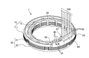
- FIG. 1 is a perspective view showing the configuration of the stator structure according to the embodiment.
- FIG. 2 is another perspective view showing the configuration of the stator structure according to the embodiment.
- FIG. 3 is an enlarged perspective view showing an internal wiring structure of the stator structure according to the embodiment.
- FIG. 4 is a diagram (1) for explaining an assembly process of the stator structure according to the embodiment.
- FIG. 5 is a diagram (2) for explaining the assembly process of the stator structure according to the embodiment.
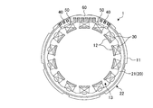
- FIG. 6 is a top view showing the configuration of the resolver according to the embodiment.
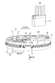
- FIG. 7 is a perspective view showing the configuration of a stator structure according to another embodiment.
- stator structure and a resolver according to an embodiment will be described with reference to the drawings.
- the application of the stator structure and the resolver is not limited by the embodiments described below.
- the drawings are schematic, and the relationship between dimensions of each element, the ratio of each element, and the like may differ from reality. Furthermore, even between the drawings, there may be portions where dimensional relationships and proportions differ from one another.
- FIG. 1 is a perspective view showing the configuration of a stator structure 1 according to the embodiment
- FIG. 2 is another perspective view showing the configuration of the stator structure 1 according to the embodiment.
- the stator structure 1 includes a stator core 10, an insulator 20, a plurality of coils 30, a plurality of terminals 40, a terminal block portion 50, and a lead wire holding portion 60.
- the coil 30 is illustrated cyclically for convenience, the embodiment is wound around each of the plurality of teeth 12 as shown in FIG. 5.
- the stator core 10 has a laminated structure in which a plurality of steel plates formed of a soft magnetic material such as an electromagnetic steel plate are laminated.
- the stator core 10 has a main body 11 and a plurality of teeth 12.
- the main body portion 11 is annular, and in the embodiment is annular.
- the plurality of teeth 12 extend from the inner peripheral side of the main body portion 11 toward the center of the main body portion 11 (that is, in the radial direction).
- the stator core 10 is configured by laminating a plurality of cores manufactured by pressing a steel plate such as an electromagnetic steel plate.
- the radial direction is a direction orthogonal to the rotation axis of the rotor 2 (see FIG. 6) rotating inside the stator core 10
- the “axial direction” is the axial direction of the rotation axis of the rotor 2
- the directions are coincident
- the “circumferential direction” is a direction coincident with the rotational direction of the rotor 2.
- the insulator 20 is an insulating member, and is formed, for example, by injection molding of an insulating resin.
- the insulator 20 is composed of a first insulator 21 and a second insulator 22.
- the stator core 10 is covered with the first insulator 21 and the second insulator 22 from both sides in the axial direction.
- the plurality of coils 30 are wound around each of the plurality of teeth 12 via the insulator 20, as shown in FIG.
- the coil 30 is composed of an excitation winding and an output winding.
- the output winding of the coil 30 is composed of a sin phase output winding that outputs an output signal of sin phase and a cos phase output winding that outputs an output signal of the cos phase.
- the plurality of terminals 40 are conductive members such as metal. One end of each of the plurality of terminals 40 extends in the axial direction from the terminal block 50, and the other end is accommodated in the lead wire holding portion 60. The end of the winding constituting the corresponding coil 30 is wound around one end of the terminal 40, and the other end of the terminal 40 is connected to the lead wire 100 shown in FIG. The wiring structure of the plurality of terminals 40 will be described later.
- the terminal block 50 extends in the axial direction from the main body 11 of the stator core 10.
- the terminal structure 50 is provided with a pair of terminal blocks 50, and each terminal block 50 is provided with three terminals 40 respectively.
- the lead wire holding portion 60 extends in the axial direction from above the main body portion 11 of the stator core 10. In the embodiment, the lead wire holding portion 60 is provided between the pair of terminal blocks 50. A plurality of hole-shaped insertion portions 61 are formed in the lead wire holding portion 60, and the lead wires 100 extending from an external device (not shown) are inserted into the insertion portions 61 and held.
- the lead wire 100 is electrically connected to the terminal 40 by inserting the lead wire 100 into the insertion portion 61.
- Can. For example, by applying resistance welding to a portion where lead wire 100 and terminal 40 contact, lead wire 100 and terminal 40 can be electrically connected.
- the terminal block portion 50 and the lead wire holding portion 60 are both disposed on the main body portion 11 of the stator core 10 and extend in the axial direction.
- the terminal block 50 and the lead wire holding portion 60 can be prevented from protruding outward from the main body portion 11 of the stator core 10 in the radial direction.
- the plurality of terminals 40 are arranged to extend in the axial direction, and the plurality of lead wires 100 are inserted in the insertion portion 61 in the axial direction. Thereby, the plurality of terminals 40 and the plurality of lead wires 100 can be suppressed from protruding outward in the radial direction from the main body portion 11 of the stator core 10.
- the stator structure 1 since the respective constituent members of the stator structure 1 and the lead wires 100 can be prevented from protruding outward from the main body portion 11 of the stator core 10 in the radial direction, the stator structure 1 can be reduced in diameter. Can. Therefore, according to the embodiment, since the dimensional restriction when attaching to the rotating electrical machine can be reduced, the attachability to the rotating electrical machine can be improved.
- the terminal block 50 and the lead wire holding portion 60 may be integrally formed with the first insulator 21.
- the terminal base portion 50 and the lead wire holding portion 60 can be simultaneously formed when the first insulator 21 is formed, the manufacturing process of the stator structure 1 can be simplified.
- the terminal block 50 and the lead wire holding portion 60 may be integrally formed in a substantially arc shape along the circumferential direction. Thereby, the strength can be increased as compared with the case where the terminal block 50 and the lead wire holding portion 60 are formed independently on the first insulator 21. Therefore, according to the embodiment, the reliability of the stator structure 1 can be improved.
- the terminal block 50 is formed with a through hole 51 penetrating in the radial direction.
- a slack pin (not shown) is inserted into the through hole 51 in advance. Then, by winding the end of the winding around the terminal 40 while detouring the winding with the slack pin and then removing the slack pin, it is possible to form a predetermined slack in the winding.
- the reliability of the stator structure 1 can be improved.
- FIG. 3 is an enlarged perspective view showing an internal wiring structure of the stator structure 1 according to the embodiment, and a wiring portion embedded inside is shown by a broken line.
- terminals 40 a, 40 b, and 40 c are provided as the terminals 40 on the terminal block 50 a on the left side of FIG. 3.
- terminals 40d, 40e, and 40f are provided as the terminals 40 in the terminal block 50b on the right side of FIG.
- the winding start of the excitation winding is wound on one end of the terminal 40a
- the winding end of the sin phase output winding is wound on one end of the terminal 40b
- the sin phase output is wound on one end of the terminal 40c.
- the winding start of the winding is entangled.
- the winding start of the cos phase output winding is wound on one end of the terminal 40d
- the winding end of the cos phase output winding is wound on one end of the terminal 40e
- excitation is performed on one end of the terminal 40f.
- the winding end of the winding is tangled.
- the end of the winding tangled in the terminal 40 is welded and electrically joined by TIG (Tungsten Inert Gas) welding.
- the example shown here is merely an example, and one of the excitation winding, the sin phase output winding, and the cos phase output winding may be entwined at one end of the terminals 40a to 40f.
- insertion parts 61a to 61f are formed as the insertion part 61.
- the other end of the terminal 40a is wired in the insertion portion 61a so as to extend in the circumferential direction inside the terminal base portion 50a and the lead wire holding portion 60, and the other end of the terminal 40b is a terminal block in the insertion portion 61b. It is wired so as to extend in the circumferential direction inside the portion 50a and the lead wire holding portion 60, and the other end of the terminal 40c extends in the circumferential direction in the terminal base portion 50a and the lead wire holding portion 60 in the insertion portion 61c. Wired to
- the other end of the terminal 40 d is wired so as to extend in the circumferential direction inside the terminal base portion 50 b and the lead wire holding portion 60
- the other end of the terminal 40 e is a terminal
- the other end of the terminal 40f extends in the circumferential direction in the terminal block portion 50b and the lead wire holding portion 60 in the insertion portion 61f. It is wired.
- the terminals 40 a, 40 b and 40 c are provided so as to be stacked in the axial direction inside the terminal block 50 a and the lead wire holding portion 60.
- the terminals 40 d, 40 e, 40 f are provided so as to be stacked in the axial direction inside the terminal block 50 b and the lead wire holding portion 60.
- the coil 30 is omitted.
- the terminals 40a to 40f are provided so as to be laminated inside, thereby increasing the size in the circumferential direction and the axial direction
- the wiring structure can be formed between the terminal block portions 50 a and 50 b and the lead wire holding portion 60 while suppressing the Therefore, according to the embodiment, the stator structure 1 can be miniaturized in the axial direction in addition to the circumferential direction.
- the same number of terminals 40 may be provided on the terminal block 50a and the terminal block 50b. Thereby, the number of terminals 40 stacked in the axial direction can be minimized. Therefore, according to the embodiment, the stator structure 1 can be further miniaturized in the axial direction.
- terminal block 50a and the terminal block 50b it is not always necessary to provide the same number of terminals 40 on the terminal block 50a and the terminal block 50b.
- four terminals 40 may be provided on one terminal block 50 and two terminals 40 may be provided on the other terminal block 50, or five terminals 40 may be provided on one terminal block 50, One terminal 40 may be provided on the terminal block 50.
- the insertion portions 61a to 61f are formed in line in a straight line.
- the electrodes used for the resistance welding can be easily applied to the terminals 40a to 40f.
- the workability at the time of attaching the lead wire 100 to the stator structure 1 can be improved.
- FIG. 4 is a figure (1) for demonstrating the assembly process of the stator structure 1 which concerns on embodiment,
- the coil 30 is abbreviate
- the stator structure 1 As shown in (a) to (c) of FIG. 4, in the stator structure 1, the first insulator 21, the stator core 10, and the second insulator 22 center on the rotation axis R of the rotor 2 (see FIG. 6). And assembled in order from the top.
- the 1st insulator 21 has the cyclic
- the terminal block 50 and the lead wire holding portion 60 are integrally formed on the first insulator 21. Specifically, the terminal block 50 and the lead wire holding portion 60 are integrally formed with the main portion 21 a of the first insulator 21. When the first insulator 21 is integrally formed with the terminal block 50 and the lead wire holding portion 60, the plurality of terminals 40 may be embedded by insert molding.
- the stator core 10 has an annular main body portion 11. Further, the stator core 10 is provided with a plurality of teeth 12 extending inward in the radial direction from the inner peripheral portion of the main body portion 11.
- the teeth 12 are substantially T-shaped in a plan view, and extend in the radial direction from the inner peripheral portion of the main body 11 to the inside in the radial direction, and both ends in the circumferential direction from the tip of the extension 12a.
- a protruding portion 12b protruding from the
- gaps 13 are formed between the adjacent teeth 12.
- the 2nd insulator 22 has the cyclic
- the teeth 12 of the stator core 10 are vertically sandwiched by the extending portion 21 b of the first insulator 21 and the extending portion 22 b of the second insulator 22.
- the wall 21 c of the first insulator 21 is inserted into the gap 13 of the stator core 10
- the wall 22 c of the second insulator 22 is inserted into the gap 13 of the stator core 10.
- the wall portion 22 c of the second insulator 22 is formed such that one height thereof is higher than the other height in the circumferential direction.
- the wall portion 21c of the first insulator 21 also has the same shape, the assembling workability of the stator structure 1 can be similarly improved.
- FIG. 5 is a figure (2) for demonstrating the assembly process of the stator structure 1 which concerns on embodiment.
- a coil 30 having a predetermined number of turns is wound around each tooth 12, and a slack pin is inserted into the through hole 51 (see FIG. 2). Then, while the winding is diverted by the slack pin, the end of the predetermined winding is tangled in the predetermined terminal 40. Thereafter, the slack pins are removed from the through holes 51 to obtain the stator structure 1 shown in FIG.
- FIG. 6 is a top view showing the configuration of the resolver 3 according to the embodiment.
- the resolver 3 according to the embodiment is a VR (Variable Reluctance) type resolver, and the rotor 2 is fixed to the output shaft of the rotating electrical machine, and rotates with the rotation of the output shaft. Thereby, the rotation angle of the output shaft of a rotary electric machine can be detected.
- VR Variable Reluctance
- FIG. 7 is a perspective view showing a stator structure 1 according to another embodiment.
- the same reference numerals are given to the same components as those in the above-described embodiment, and the detailed description is omitted.
- the terminal base portion 50 and the lead wire holding portion 60 are both integrally formed with the first insulator 21, and the lead wire holding portion 60 has an insertion portion 61 ( 61a to 61f) are formed. Then, the lead wire 100 is inserted into the insertion portions 61a to 61f, and the lead wire 100 is connected to the other end of the terminal 40.
- the stator structure 1 according to the other embodiment shown in FIG. 7 has a form in which the connecting portion is a connector structure instead of the method of directly connecting the lead wire 100 and the lead wire holding portion 60.
- a stator structure 1 includes a connector housing 60 ⁇ / b> A in place of the lead wire holding portion 60.
- the connector housing 60A is another example of the lead wire holding portion 60.
- the connector housing 60 ⁇ / b> A extends in the axial direction from the main body 11 of the stator core 10.
- the connector housing 60A is integrally formed with the first insulator 21, provided between the pair of terminal blocks 50, and has a shape that can be fitted with the connector 110.
- the connector 110 integrally holds the plurality of lead wires 100.
- the other end of the terminal 40 (40a to 40f) is exposed and disposed inside the connector housing 60A, and the distal end portion of the lead wire 110 is exposed and provided on the connector 110.
- the lead wire 100 and the terminal 40 can be electrically connected by inserting the connector 110 into the connector housing 60A.
- the connector housing 60A functions as a male connector
- the connector 110 functions as a female connector
- the connector housing 60A may function as a female connector
- the connector 110 may function as a male connector
- the embodiment shows an example in which the insulator 20 is divided into the first insulator 21 and the second insulator 22, the insulator 20 may be formed by insert molding so that the stator core 10 is embedded inside. .
- the embodiment shows an example in which the coil cover for protecting the coil 30 is not provided, a coil cover for protecting the coil 30 may be separately provided.
- the present invention is applied to the inner rotor type resolver 3, but the present invention may be applied to the outer rotor type resolver.
- the stator structure 1 includes the stator core 10, the insulator 20, the plurality of coils 30, the plurality of terminals 40, the terminal block 50, and the lead wire holding portion 60.
- the stator core 10 has an annular main body portion 11 and a plurality of teeth 12 extending in the radial direction from the main body portion 11 and arranged along the circumferential direction of the main body portion 11.
- the insulator 20 covers the plurality of teeth 12.
- the plurality of coils 30 are wound around each of the plurality of teeth 12 via the insulator 20.
- the plurality of terminals 40 extend in the axial direction of the stator core 10, and the ends of the windings constituting the coil 30 are entangled at one end.
- the terminal block 50 is disposed on the main body 11 of the stator core 10 and holds a plurality of terminals 40.
- the lead wire holding portion 60 is disposed on the main body portion 11 of the stator core 10, accommodates the other end of the plurality of terminals 40, and the lead wire 100 is axially inserted and connected to the other end. Thereby, the attachment property to a rotary electric machine can be improved.
- the terminal block portions 50a and 50b are provided in a pair, and the pair of terminal block portions 50a and 50b are disposed on both sides of the lead wire holding portion 60. Thereby, the stator structure 1 can be miniaturized in the axial direction as well.
- stator structure 1 which concerns on embodiment, a pair of terminal block part 50a, 50b hold
- stator structure 1 according to the embodiment, the insulator 20, the terminal block portion 50, and the lead wire holding portion 60 are integrally formed. Thereby, the reliability of the stator structure 1 can be improved.
- the plurality of terminals 40 are provided so as to be axially stacked inside the terminal block 50 and the lead wire holding portion 60.
- the stator structure 1 can be miniaturized in the axial direction in addition to the radial direction.
- the lead wire holding portion 60 is formed as the connector housing 60A, and the lead wire 100 is held by the connector 110 that can be fitted to the connector housing 60A. Thereby, the workability at the time of connecting lead wire 100 to terminal 40 can be improved.
- the resolver 3 includes the rotor 2 and the stator structure 1 described above. Thereby, the resolver 3 which improved the attachment property to a rotary electric machine is realizable.
- the present invention is not limited by the above embodiment. What is configured by appropriately combining the above-described constituents is also included in the present invention. Further, further effects and modifications can be easily derived by those skilled in the art. Therefore, the broader aspects of the present invention are not limited to the above embodiment, and various modifications are possible.
Landscapes
- Engineering & Computer Science (AREA)
- Power Engineering (AREA)
- Insulation, Fastening Of Motor, Generator Windings (AREA)
- Motor Or Generator Frames (AREA)
Abstract
実施形態のステータ構造(1)は、ステータコア(10)と、インシュレータ(20)と、複数のコイル(30)と、複数の端子(40)と、端子台部(50)と、リード線保持部(60)と、を備える。ステータコア(10)は、環状の本体部(11)と、本体部(11)から径方向に延在し本体部(11)の周方向に沿って配列される複数のティース(12)とを有する。インシュレータ(20)は、複数のティース(12)を覆う。複数のコイル(30)は、インシュレータ(20)を介して複数のティース(12)のそれぞれに巻回される。複数の端子(40)は、ステータコア(10)の軸方向に延在し、コイル(30)を構成する巻線の末端が一端に絡げられる。端子台部(50)は、ステータコア(10)の本体部(11)上に配置され、複数の端子(40)を保持する。リード線保持部(60)は、ステータコア(10)の本体部(11)上に配置され、複数の端子(40)の他端を収納し、リード線(100)が軸方向に挿入されて他端に接続される。
Description
本発明は、ステータ構造およびレゾルバに関する。
従来、モータや発電機などの回転電機の回転角度を検出するレゾルバが知られている。かかるレゾルバは、たとえば、環状に形成された本体部の内周側から中心に向かって延在する複数のティースを備えたステータコアと、かかるステータコアの内側で複数のティースに対向配置されるロータとを備える。また、ティースにはインシュレータを介して巻線が巻回されており、かかる巻線は端子の一端に絡げられる。そして、かかる端子の他端がリード線保持部に延びるように配置され、かかるリード線保持部で外部装置から延びるリード線に接続される(たとえば、特許文献1参照)。
しかしながら、従来の技術では、リード線保持部がステータコアの外周側から外方に突出して設けられることから、レゾルバの外径寸法が大きくなり、回転電機に取り付ける際に寸法的な制約が生じる恐れがあった。
本発明は、上記に鑑みてなされたものであって、回転電機への取り付け性を向上させることができるステータ構造およびレゾルバを提供することを目的とする。
上述した課題を解決し、目的を達成するために、本発明の一態様に係るステータ構造は、ステータコアと、インシュレータと、複数のコイルと、複数の端子と、端子台部と、リード線保持部と、を備える。前記ステータコアは、環状の本体部と、前記本体部から径方向に延在し前記本体部の周方向に沿って配列される複数のティースとを有する。前記インシュレータは、前記複数のティースを覆う。前記複数のコイルは、前記インシュレータを介して前記複数のティースのそれぞれに巻回される。前記複数の端子は、前記ステータコアの軸方向に延在し、前記コイルを構成する巻線の末端が一端に絡げられる。前記端子台部は、前記ステータコアの前記本体部上に配置され、前記複数の端子を保持する。前記リード線保持部は、前記ステータコアの前記本体部上に配置され、前記複数の端子の他端を収納し、リード線が前記軸方向に挿入されて前記他端に接続される。
本発明の一態様によれば、回転電機への取り付け性を向上させることができる。
以下、実施形態に係るステータ構造およびレゾルバについて図面を参照して説明する。なお、以下に説明する実施形態によりステータ構造およびレゾルバの用途が限定されるものではない。また、図面は模式的なものであり、各要素の寸法の関係、各要素の比率などは、現実と異なる場合があることに留意する必要がある。さらに、図面の相互間においても、互いの寸法の関係や比率が異なる部分が含まれている場合がある。
(ステータ構造の構成)
最初に、実施形態に係るステータ構造1の詳細について、図1および図2を参照しながら説明する。図1は、実施形態に係るステータ構造1の構成を示す斜視図であり、図2は、実施形態に係るステータ構造1の構成を示す別の斜視図である。
最初に、実施形態に係るステータ構造1の詳細について、図1および図2を参照しながら説明する。図1は、実施形態に係るステータ構造1の構成を示す斜視図であり、図2は、実施形態に係るステータ構造1の構成を示す別の斜視図である。
図1に示すように、ステータ構造1は、ステータコア10と、インシュレータ20と、複数のコイル30と、複数の端子40と、端子台部50と、リード線保持部60とを備える。なお、コイル30は便宜上、環状で図示しているが、実施形態は図5に示すように、複数のティース12のそれぞれに巻回されている。
ステータコア10は、電磁鋼板などの軟磁性材料から形成された鋼板を複数枚積層した積層構造を有する。ステータコア10は、本体部11と、複数のティース12とを有する。本体部11は、環状であり、実施形態では円環状である。複数のティース12は、本体部11の内周側から本体部11の中心に向かって(すなわち、径方向に)延在する。そして、ステータコア10は、電磁鋼板などの鋼板をプレス加工して製作されたコアを複数枚積層して構成される。
なお、以降においては、図1に示すように、ステータコア10の径方向、軸方向および周方向を規定して説明する。ここで、「径方向」とは、ステータコア10の内側で回転するロータ2(図6参照)の回転軸と直交する方向であり、「軸方向」とは、ロータ2の回転軸の軸方向と一致する方向であり、「周方向」とは、ロータ2の回転方向と一致する方向である。
インシュレータ20は、絶縁性の部材であり、たとえば、絶縁性樹脂の射出成形によって成形される。インシュレータ20は、第1インシュレータ21と第2インシュレータ22とで構成される。そして、かかる第1インシュレータ21と第2インシュレータ22とで、ステータコア10を軸方向の両側から覆っている。
複数のコイル30は、図5に示すように、インシュレータ20を介して、複数のティース12のそれぞれに巻回される。かかるコイル30は、励磁巻線と出力巻線とにより構成される。また、コイル30の出力巻線は、sin相の出力信号を出力するsin相出力巻線と、cos相の出力信号を出力するcos相出力巻線とにより構成される。
複数の端子40は、金属などの導電性の部材である。複数の端子40は、一端が端子台部50から軸方向に突出するように延在し、他端がリード線保持部60に収容される。端子40の一端には、対応するコイル30を構成する巻線の末端が絡げられ、端子40の他端には、図2に示すリード線100が接続される。かかる複数の端子40の配線構造については後述する。
端子台部50は、ステータコア10の本体部11上から軸方向に延在する。実施形態では、ステータ構造1に端子台部50が一対設けられており、各端子台部50にそれぞれ3本の端子40が設けられる。
リード線保持部60は、ステータコア10の本体部11上から軸方向に延在する。実施形態では、リード線保持部60が一対の端子台部50の間に設けられる。リード線保持部60には、穴状の挿入部61が複数形成され、かかる挿入部61に外部装置(図示せず)から延びるリード線100が挿入されて保持される。
そして、挿入部61には端子40の他端が露出して設けられていることから、リード線100を挿入部61に挿入することにより、リード線100と端子40とを電気的に接続することができる。たとえば、リード線100と端子40とが接触する部分に抵抗溶接を施すことにより、リード線100と端子40とを電気的に接続することができる。
ここで、実施形態では、図1などに示すように、端子台部50およびリード線保持部60が、いずれもステータコア10の本体部11上に配置されるとともに、軸方向に延在する。これにより、端子台部50およびリード線保持部60が、ステータコア10の本体部11から径方向における外側にはみ出すことを抑制することができる。
また、実施形態では、図2に示すように、複数の端子40が軸方向に延びるように配置され、複数のリード線100が挿入部61に軸方向に挿入される。これにより、複数の端子40および複数のリード線100が、ステータコア10の本体部11から、径方向における外側にはみ出すことを抑制することができる。
すなわち、実施形態では、ステータ構造1の各構成部材やリード線100が、ステータコア10の本体部11から、径方向における外側にはみ出すことを抑制することができることから、ステータ構造1を小径化することができる。したがって、実施形態によれば、回転電機に取り付ける際の寸法的な制約を少なくすることができることから、回転電機への取り付け性を向上させることができる。
また、実施形態では、端子台部50およびリード線保持部60が、いずれも第1インシュレータ21と一体で形成されるとよい。これにより、第1インシュレータ21を形成する際に端子台部50およびリード線保持部60を同時に形成することができることから、ステータ構造1の製造工程を簡素化することができる。
また、実施形態では、図1に示すように、端子台部50およびリード線保持部60が、周方向に沿って略円弧状に一体で形成されるとよい。これにより、端子台部50とリード線保持部60とをそれぞれ第1インシュレータ21上に独立させて形成する場合に比べて、強度を高くすることができる。したがって、実施形態によれば、ステータ構造1の信頼性を向上させることができる。
なお、実施形態では、図2に示すように、端子台部50には径方向に貫通する貫通孔51が形成される。ここで、ティース12に巻回された巻線の末端を端子40の一端に絡げる際に、あらかじめ貫通孔51に図示しないたるみピンを挿入しておく。そして、かかるたるみピンで巻線を迂回させながら端子40に巻線の末端を絡げて、その後たるみピンを外すことにより、巻線に所定のたるみを形成することができる。
これにより、巻線が熱収縮する場合でも、形成されたたるみにより巻線が切れることを抑制することができる。したがって、実施形態によれば、ステータ構造1の信頼性を向上させることができる。
(ステータ構造の内部配線構造)
つづいて、ステータ構造1の内部配線構造について、図3を参照しながら説明する。図3は、実施形態に係るステータ構造1の内部配線構造を示す拡大斜視図であり、内部に埋め込まれた配線部分については破線で示している。
つづいて、ステータ構造1の内部配線構造について、図3を参照しながら説明する。図3は、実施形態に係るステータ構造1の内部配線構造を示す拡大斜視図であり、内部に埋め込まれた配線部分については破線で示している。
図3に示すように、一対の端子台部50のうち、図3左側の端子台部50aには、端子40として、端子40a、40b、40cが設けられる。また、図3右側の端子台部50bには、端子40として、端子40d、40e、40fが設けられる。
たとえば、端子40aの一端には、励磁巻線の巻き始めが絡げられ、端子40bの一端には、sin相出力巻線の巻き終わりが絡げられ、端子40cの一端には、sin相出力巻線の巻き始めが絡げられる。また、端子40dの一端には、cos相出力巻線の巻き始めが絡げられ、端子40eの一端には、cos相出力巻線の巻き終わりが絡げられ、端子40fの一端には、励磁巻線の巻き終わりが絡げられる。そして、端子40に絡げられた巻線の端末は、TIG(Tungsten Inert Gas)溶接にて溶着して電気的に接合する。
なお、ここで示した例はあくまで一例であり、端子40a~40fの一端には励磁巻線、sin相出力巻線、cos相出力巻線のうちいずれかが絡げられていればよい。
また、リード線保持部60には、挿入部61として、挿入部61a~61fが形成される。そして、挿入部61aには、端子40aの他端が端子台部50aおよびリード線保持部60の内部を周方向に延びるように配線され、挿入部61bには、端子40bの他端が端子台部50aおよびリード線保持部60の内部を周方向に延びるように配線され、挿入部61cには、端子40cの他端が端子台部50aおよびリード線保持部60の内部を周方向に延びるように配線される。
同様に、挿入部61dには、端子40dの他端が端子台部50bおよびリード線保持部60の内部を周方向に延びるように配線され、挿入部61eには、端子40eの他端が端子台部50bおよびリード線保持部60の内部を周方向に延びるように配線され、挿入部61fには、端子40fの他端が端子台部50bおよびリード線保持部60の内部を周方向に延びるように配線される。
ここで、図3に示すように、端子40a、40b、40cは、端子台部50aおよびリード線保持部60の内部で軸方向に積層するように設けられる。同様に、端子40d、40e、40fは、端子台部50bおよびリード線保持部60の内部で軸方向に積層するように設けられる。なお、コイル30は省略している。
ここまで説明したように、一対の端子台部50a、50bをリード線保持部60の両側に設けるとともに、端子40a~40fを内部に積層するように設けることにより、周方向および軸方向における寸法増加を抑えながら、端子台部50a、50bとリード線保持部60との間に配線構造を形成することができる。したがって、実施形態によれば、周方向に加えて、ステータ構造1を軸方向にも小型化することができる。
さらに、実施形態では、端子台部50aおよび端子台部50bに、同じ数の端子40を設けるとよい。これにより、軸方向に積層される端子40の数を最小化することができる。したがって、実施形態によれば、ステータ構造1を軸方向にさらに小型化することができる。
一方で、軸方向における寸法の制約が小さい場合であれば、必ずしも端子台部50aおよび端子台部50bに、同じ数の端子40を設ける必要はない。たとえば、一方の端子台部50に端子40を4個設け、他方の端子台部50に端子40を2個設けてもよいし、一方の端子台部50に端子40を5個設け、他方の端子台部50に端子40を1個設けてもよい。
また、実施形態では、図3に示すように、リード線保持部60において、挿入部61a~61fが直線状に並んで形成される。これにより、リード線100を挿入部61a~61f内の端子40a~40fに抵抗溶接する際に、かかる抵抗溶接に用いられる電極を端子40a~40fに当てやすくすることができる。
したがって、実施形態によれば、ステータ構造1にリード線100を組み付ける際の作業性を向上させることができる。
(ステータ構造およびレゾルバの組立工程)
つづいて、実施形態に係るステータ構造1およびレゾルバの組立工程について、図4~図6を参照しながら説明する。図4は、実施形態に係るステータ構造1の組立工程を説明するための図(1)で、コイル30は省略してある。
つづいて、実施形態に係るステータ構造1およびレゾルバの組立工程について、図4~図6を参照しながら説明する。図4は、実施形態に係るステータ構造1の組立工程を説明するための図(1)で、コイル30は省略してある。
図4の(a)~(c)に示すように、ステータ構造1は、第1インシュレータ21と、ステータコア10と、第2インシュレータ22とが、ロータ2(図6参照)の回転軸Rを中心にして、上から順に積層して組み立てられる。
図4の(a)に示すように、第1インシュレータ21は、環状の本体部21aを有する。また、第1インシュレータ21には、本体部21aの内周部から径方向に内側に延在する複数の延在部21bと、かかる延在部21bの縁部から下方に突出する壁部21cと、延在部21bの先端部から上方に突出する壁部21dとが設けられる。
また、第1インシュレータ21には、端子台部50およびリード線保持部60が一体で形成される。具体的には、端子台部50およびリード線保持部60が、第1インシュレータ21の本体部21aと一体で形成される。なお、第1インシュレータ21を端子台部50およびリード線保持部60と一体で形成する際に、複数の端子40をインサート成形により埋め込むとよい。
図4の(b)に示すように、ステータコア10は、環状の本体部11を有する。また、ステータコア10には、本体部11の内周部から径方向に内側に延在するティース12が複数設けられる。かかるティース12は、平面視で略T字形状であり、本体部11の内周部から径方向に内側に延在する延在部12aと、かかる延在部12aの先端部から周方向に両側に突出する凸部12bとを有する。また、隣接するティース12の間には、間隙13が形成される。
図4の(c)に示すように、第2インシュレータ22は、環状の本体部22aを有する。また、第2インシュレータ22には、本体部22aの内周部から径方向に内側に延在する複数の延在部22bと、本体部22aの内周部および延在部22bの縁部から上方に突出する壁部22cと、延在部22bの先端部から下方に突出する壁部22dとが設けられる。
そして、ステータ構造1の組立工程では、ステータコア10のティース12を、第1インシュレータ21の延在部21bと第2インシュレータ22の延在部22bとで上下から挟み込む。この際、第1インシュレータ21の壁部21cをステータコア10の間隙13に挿入するとともに、第2インシュレータ22の壁部22cをステータコア10の間隙13に挿入する。
ここで、図4の(c)に示すように、第2インシュレータ22の壁部22cは、周方向において一方の高さが他方の高さより高くなるように形成される。これにより、壁部22cの上部全面を正確に位置合わせすることなく間隙13に挿入することができることから、壁部22cを間隙13に容易に挿入することができる。したがって、実施形態によれば、ステータ構造1の組立作業性を向上させることができる。
なお、図4の(a)では明示されていないが、第1インシュレータ21の壁部21cも同様の形状を有することから、同様にステータ構造1の組立作業性を向上させることができる。
つづいて、図5に示すように、第1インシュレータ21とステータコア10と第2インシュレータ22とで構成される積層体に対して、ティース12の延在部12aの箇所にコイル30が巻回される。図5は、実施形態に係るステータ構造1の組立工程を説明するための図(2)である。
この工程では、各ティース12に対して所定のターン数のコイル30が巻回されるとともに、貫通孔51(図2参照)にたるみピンが挿入される。そして、かかるたるみピンで巻線を迂回させながら所定の端子40に所定の巻線の末端が絡げられる。その後、たるみピンが貫通孔51から外されて、図5に示すステータ構造1が得られる。
さらに、図6に示すように、得られたステータ構造1の内側にロータ2を設けることにより、レゾルバ3が得られる。図6は、実施形態に係るレゾルバ3の構成を示す上面図である。実施形態に係るレゾルバ3は、VR(Variable Reluctance)型レゾルバであり、ロータ2は、回転電機の出力軸に固定され、かかる出力軸の回転に伴って回転する。これにより、回転電機の出力軸の回転角度を検出することができる。
(他の実施形態)
つづいて、他の実施形態に係るステータ構造1について、図7を参照しながら説明する。図7は、他の実施形態に係るステータ構造1を示す斜視図である。なお、以降の説明においては、上述の実施形態と共通の構成については同一の符号を付して、詳細な説明は省略する。
つづいて、他の実施形態に係るステータ構造1について、図7を参照しながら説明する。図7は、他の実施形態に係るステータ構造1を示す斜視図である。なお、以降の説明においては、上述の実施形態と共通の構成については同一の符号を付して、詳細な説明は省略する。
図1などで示した実施形態に係るステータ構造1は、端子台部50およびリード線保持部60が、いずれも第1インシュレータ21と一体で形成され、リード線保持部60には挿入部61(61a~61f)が形成されている。そして、かかる挿入部61a~61fにリード線100を挿入し、端子40の他端にリード線100が接続される構成である。
これに対して、図7に示す他の実施形態に係るステータ構造1は、リード線100とリード線保持部60とを直接接続する方法に代えて、接続部分をコネクタ構造にした形態である。
図7に示すように、他の実施形態に係るステータ構造1は、リード線保持部60に代えて、コネクタハウジング60Aを備える。かかるコネクタハウジング60Aは、リード線保持部60の別の一例である。
コネクタハウジング60Aは、ステータコア10の本体部11上から軸方向に延在する。また、コネクタハウジング60Aは、第1インシュレータ21と一体成形されて、一対の端子台部50の間に設けられ、コネクタ110と嵌合可能な形状を有する。コネクタ110は、複数のリード線100を一体で保持する。
また、コネクタハウジング60Aの内部には端子40(40a~40f)の他端が露出して配設されており、コネクタ110にはリード線110の先端部が露出して設けられている。そして、コネクタ110をコネクタハウジング60Aに挿入することにより、リード線100と端子40とを電気的に接続することができる。
すなわち、コネクタハウジング60Aはオスのコネクタとして機能し、コネクタ110はメスのコネクタとして機能する。なお、コネクタハウジング60Aがメスのコネクタとして機能し、コネクタ110がオスのコネクタとして機能してもよい。
図7に示す他の実施形態によれば、リード線100を端子40の他端に接続する作業が不要となるため、リード線100を端子40に接続する際の作業性を向上させることができる。
以上、本発明の各実施形態について説明したが、本発明は上記実施形態に限定されるものではなく、その趣旨を逸脱しない限りにおいて種々の変更が可能である。たとえば、実施形態では、インシュレータ20が第1インシュレータ21と第2インシュレータ22とに分割された例について示したが、ステータコア10が内部に埋め込まれるように、インサート成形でインシュレータ20を形成してもよい。
また、実施形態では、一対の端子台部50a、50bがリード線保持部60の両側に設けられた例について示したが、一つの端子台部50をリード線保持部60に隣接して設けてもよい。
さらに、実施形態では、コイル30を保護するコイルカバーが設けられていない例について示したが、コイル30を保護するコイルカバーを別途設けてもよい。また、実施形態では、インナーロータ型のレゾルバ3に本発明を適用した場合について示したが、アウターロータ型のレゾルバに本発明を適用してもよい。
以上のように、実施形態に係るステータ構造1は、ステータコア10と、インシュレータ20と、複数のコイル30と、複数の端子40と、端子台部50と、リード線保持部60と、を備える。ステータコア10は、環状の本体部11と、本体部11から径方向に延在し本体部11の周方向に沿って配列される複数のティース12とを有する。インシュレータ20は、複数のティース12を覆う。複数のコイル30は、インシュレータ20を介して複数のティース12のそれぞれに巻回される。複数の端子40は、ステータコア10の軸方向に延在し、コイル30を構成する巻線の末端が一端に絡げられる。端子台部50は、ステータコア10の本体部11上に配置され、複数の端子40を保持する。リード線保持部60は、ステータコア10の本体部11上に配置され、複数の端子40の他端を収納し、リード線100が軸方向に挿入されて他端に接続される。これにより、回転電機への取り付け性を向上させることができる。
また、実施形態に係るステータ構造1において、端子台部50a、50bは一対設けられ、一対の端子台部50a、50bがリード線保持部60の両側に配置される。これにより、ステータ構造1を軸方向にも小型化することができる。
また、実施形態に係るステータ構造1において、一対の端子台部50a、50bは、それぞれ同じ数の端子40を保持する。これにより、ステータ構造1を軸方向にさらに小型化することができる。
また、実施形態に係るステータ構造1において、インシュレータ20と端子台部50とリード線保持部60とが一体で形成される。これにより、ステータ構造1の信頼性を向上させることができる。
また、実施形態に係るステータ構造1において、複数の端子40は、端子台部50およびリード線保持部60の内部で軸方向に積層するように設けられる。これにより、径方向に加えて、ステータ構造1を軸方向にも小型化することができる。
また、実施形態に係るステータ構造1において、リード線保持部60は、コネクタハウジング60Aとして形成され、リード線100は、コネクタハウジング60Aと嵌合可能なコネクタ110に保持される。これにより、リード線100を端子40に接続する際の作業性を向上させることができる。
また、実施形態に係るレゾルバ3は、ロータ2と、上述のステータ構造1とを備える。これにより、回転電機への取り付け性を向上させたレゾルバ3を実現することができる。
また、上記実施の形態により本発明が限定されるものではない。上述した各構成素を適宜組み合わせて構成したものも本発明に含まれる。また、さらなる効果や変形例は、当業者によって容易に導き出すことができる。よって、本発明のより広範な態様は、上記の実施の形態に限定されるものではなく、様々な変更が可能である。
1 ステータ構造,2 ロータ,3 レゾルバ,10 ステータコア,11 本体部,12 ティース,20 インシュレータ,21 第1インシュレータ,22 第2インシュレータ,30 コイル,40、40a~40f 端子,50 端子台部,51 貫通孔,60 リード線保持部,60A コネクタハウジング,61、61a~61f 挿入部,100 リード線,110 コネクタ
Claims (7)
- 環状の本体部と、前記本体部から径方向に延在し前記本体部の周方向に沿って配列される複数のティースとを有するステータコアと、
前記複数のティースを覆うインシュレータと、
前記インシュレータを介して前記複数のティースのそれぞれに巻回される複数のコイルと、
前記ステータコアの軸方向に延在し、前記コイルを構成する巻線の末端が一端に絡げられる複数の端子と、
前記ステータコアの前記本体部上に配置され、前記複数の端子を保持する端子台部と、
前記ステータコアの前記本体部上に配置され、前記複数の端子の他端を収納し、リード線が前記軸方向に挿入されて前記他端に接続されるリード線保持部と、
を備える、ステータ構造。 - 前記端子台部は一対設けられ、
一対の前記端子台部が前記リード線保持部の両側に配置される、請求項1に記載のステータ構造。 - 一対の前記端子台部は、それぞれ同じ数の前記端子を保持する、請求項2に記載のステータ構造。
- 前記インシュレータと前記端子台部と前記リード線保持部とが一体で形成される、請求項1~3のいずれか一つに記載のステータ構造。
- 前記複数の端子は、前記端子台部および前記リード線保持部の内部で前記軸方向に積層するように設けられる、請求項4に記載のステータ構造。
- 前記リード線保持部は、コネクタハウジングとして形成され、
前記リード線は、前記コネクタハウジングと嵌合可能なコネクタに保持される、請求項1~5のいずれか一つに記載のステータ構造。 - ロータと、
請求項1~6のいずれか一つに記載のステータ構造と、
を備える、レゾルバ。
Priority Applications (2)
| Application Number | Priority Date | Filing Date | Title |
|---|---|---|---|
| JP2019539607A JP6983246B2 (ja) | 2017-08-31 | 2018-08-30 | ステータ構造およびレゾルバ |
| CN201880055305.9A CN111095754B (zh) | 2017-08-31 | 2018-08-30 | 定子构造以及旋转变压器 |
Applications Claiming Priority (2)
| Application Number | Priority Date | Filing Date | Title |
|---|---|---|---|
| JP2017-167679 | 2017-08-31 | ||
| JP2017167679 | 2017-08-31 |
Publications (1)
| Publication Number | Publication Date |
|---|---|
| WO2019044953A1 true WO2019044953A1 (ja) | 2019-03-07 |
Family
ID=65527347
Family Applications (1)
| Application Number | Title | Priority Date | Filing Date |
|---|---|---|---|
| PCT/JP2018/032064 Ceased WO2019044953A1 (ja) | 2017-08-31 | 2018-08-30 | ステータ構造およびレゾルバ |
Country Status (3)
| Country | Link |
|---|---|
| JP (1) | JP6983246B2 (ja) |
| CN (1) | CN111095754B (ja) |
| WO (1) | WO2019044953A1 (ja) |
Cited By (2)
| Publication number | Priority date | Publication date | Assignee | Title |
|---|---|---|---|---|
| JP2022047127A (ja) * | 2020-09-11 | 2022-03-24 | 多摩川精機株式会社 | レゾルバステータ構造 |
| JP2023059637A (ja) * | 2021-10-15 | 2023-04-27 | ミネベアミツミ株式会社 | レゾルバ |
Families Citing this family (3)
| Publication number | Priority date | Publication date | Assignee | Title |
|---|---|---|---|---|
| CN113782315B (zh) * | 2021-09-15 | 2022-06-03 | 上海赢双电机有限公司 | 分体式旋转变压器绝缘骨架结构 |
| JP2023050858A (ja) * | 2021-09-30 | 2023-04-11 | 日本電産株式会社 | モータ |
| CN118232589A (zh) * | 2024-04-30 | 2024-06-21 | 东莞市本末科技有限公司 | 电机 |
Citations (8)
| Publication number | Priority date | Publication date | Assignee | Title |
|---|---|---|---|---|
| JP2003125551A (ja) * | 2001-10-12 | 2003-04-25 | Minebea Co Ltd | レゾルバのリード端子構造 |
| JP2004072867A (ja) * | 2002-08-05 | 2004-03-04 | Tamagawa Seiki Co Ltd | レゾルバステータのステータコイルの端子接続構造 |
| JP2005184952A (ja) * | 2003-12-18 | 2005-07-07 | Tamagawa Seiki Co Ltd | レゾルバステータ構造 |
| JP2006109658A (ja) * | 2004-10-07 | 2006-04-20 | Tamagawa Seiki Co Ltd | レゾルバ外部導線固定構造 |
| JP2012135078A (ja) * | 2010-12-20 | 2012-07-12 | Tamagawa Seiki Co Ltd | レゾルバ構造 |
| JP2012249417A (ja) * | 2011-05-27 | 2012-12-13 | Ckd Corp | 多段式レゾルバ |
| JP2015027221A (ja) * | 2013-07-29 | 2015-02-05 | ミネベア株式会社 | Vr型レゾルバのステータ構造およびvr型レゾルバ |
| JP2017131030A (ja) * | 2016-01-20 | 2017-07-27 | 多摩川精機株式会社 | レゾルバのリード線固定構造 |
Family Cites Families (9)
| Publication number | Priority date | Publication date | Assignee | Title |
|---|---|---|---|---|
| JP4138823B2 (ja) * | 2006-07-04 | 2008-08-27 | 本田技研工業株式会社 | モータのステータ構造 |
| JP5703604B2 (ja) * | 2010-03-03 | 2015-04-22 | 日本電産株式会社 | バスバーユニット及びモータ |
| CN102377254B (zh) * | 2011-10-25 | 2016-05-04 | 佛山市威灵洗涤电机制造有限公司 | 洗衣机用塑模电机的定子结构 |
| WO2015040852A1 (ja) * | 2013-09-17 | 2015-03-26 | パナソニックIpマネジメント株式会社 | ブラシレスdcモータおよびそれを搭載した送風装置 |
| JP6267907B2 (ja) * | 2013-09-26 | 2018-01-24 | 株式会社ミツバ | バスバーユニットおよびブラシレスモータ |
| JP6303093B2 (ja) * | 2014-03-25 | 2018-04-04 | 多摩川精機株式会社 | 車載用アングル型コネクタ一体型サーボモータのコネクタの製造方法 |
| JP6208717B2 (ja) * | 2015-06-24 | 2017-10-04 | ミネベアミツミ株式会社 | レゾルバ |
| JP6406206B2 (ja) * | 2015-10-20 | 2018-10-17 | トヨタ自動車株式会社 | 回転電機の端子台接続構造 |
| JP6378660B2 (ja) * | 2015-11-16 | 2018-08-22 | ミネベアミツミ株式会社 | ステータ構造およびレゾルバ |
-
2018
- 2018-08-30 JP JP2019539607A patent/JP6983246B2/ja active Active
- 2018-08-30 CN CN201880055305.9A patent/CN111095754B/zh active Active
- 2018-08-30 WO PCT/JP2018/032064 patent/WO2019044953A1/ja not_active Ceased
Patent Citations (8)
| Publication number | Priority date | Publication date | Assignee | Title |
|---|---|---|---|---|
| JP2003125551A (ja) * | 2001-10-12 | 2003-04-25 | Minebea Co Ltd | レゾルバのリード端子構造 |
| JP2004072867A (ja) * | 2002-08-05 | 2004-03-04 | Tamagawa Seiki Co Ltd | レゾルバステータのステータコイルの端子接続構造 |
| JP2005184952A (ja) * | 2003-12-18 | 2005-07-07 | Tamagawa Seiki Co Ltd | レゾルバステータ構造 |
| JP2006109658A (ja) * | 2004-10-07 | 2006-04-20 | Tamagawa Seiki Co Ltd | レゾルバ外部導線固定構造 |
| JP2012135078A (ja) * | 2010-12-20 | 2012-07-12 | Tamagawa Seiki Co Ltd | レゾルバ構造 |
| JP2012249417A (ja) * | 2011-05-27 | 2012-12-13 | Ckd Corp | 多段式レゾルバ |
| JP2015027221A (ja) * | 2013-07-29 | 2015-02-05 | ミネベア株式会社 | Vr型レゾルバのステータ構造およびvr型レゾルバ |
| JP2017131030A (ja) * | 2016-01-20 | 2017-07-27 | 多摩川精機株式会社 | レゾルバのリード線固定構造 |
Cited By (4)
| Publication number | Priority date | Publication date | Assignee | Title |
|---|---|---|---|---|
| JP2022047127A (ja) * | 2020-09-11 | 2022-03-24 | 多摩川精機株式会社 | レゾルバステータ構造 |
| JP7466868B2 (ja) | 2020-09-11 | 2024-04-15 | 多摩川精機株式会社 | レゾルバステータ構造 |
| JP2023059637A (ja) * | 2021-10-15 | 2023-04-27 | ミネベアミツミ株式会社 | レゾルバ |
| JP7695858B2 (ja) | 2021-10-15 | 2025-06-19 | ミネベアミツミ株式会社 | レゾルバ |
Also Published As
| Publication number | Publication date |
|---|---|
| CN111095754B (zh) | 2022-06-03 |
| JP6983246B2 (ja) | 2021-12-17 |
| CN111095754A (zh) | 2020-05-01 |
| JPWO2019044953A1 (ja) | 2020-10-01 |
Similar Documents
| Publication | Publication Date | Title |
|---|---|---|
| CN108808898B (zh) | 定子以及旋转变压器 | |
| WO2019044953A1 (ja) | ステータ構造およびレゾルバ | |
| JP5827840B2 (ja) | Vr型レゾルバ | |
| JP6444930B2 (ja) | 巻線を圧着結線して構成される配線基板を備える電動機 | |
| JP5552631B2 (ja) | コンデンサ形単相誘導電動機 | |
| JP2015133772A (ja) | バスバーモジュールおよび回転電機 | |
| JP2013211956A (ja) | 回転電機 | |
| JP6608864B2 (ja) | レゾルバ | |
| JP2019126241A (ja) | ステータ構造およびレゾルバ | |
| CN108258854A (zh) | 马达 | |
| JP2019146367A (ja) | ステータ構造およびレゾルバ | |
| JP2019050670A (ja) | ステータ構造およびレゾルバ | |
| JP7076277B2 (ja) | ステータ構造およびレゾルバ | |
| JP2015080300A (ja) | 電機子、回転電機、電機子の製造方法 | |
| JP6853149B2 (ja) | ステータ構造およびレゾルバ | |
| JP6339052B2 (ja) | レゾルバ | |
| JP6684749B2 (ja) | モータ | |
| JP6080964B2 (ja) | 回転電機の固定子 | |
| JP6710180B2 (ja) | モータ | |
| JP2021010218A (ja) | ステータ構造およびレゾルバ | |
| CN113098176B (zh) | 旋转电机 | |
| JP2019075902A (ja) | ステータ構造およびレゾルバ | |
| JP4971417B2 (ja) | ステータ及びブラシレスモータ | |
| JP2020127362A (ja) | モータ | |
| JP2016152677A (ja) | 可変リラクタンス型レゾルバ |
Legal Events
| Date | Code | Title | Description |
|---|---|---|---|
| 121 | Ep: the epo has been informed by wipo that ep was designated in this application |
Ref document number: 18852575 Country of ref document: EP Kind code of ref document: A1 |
|
| ENP | Entry into the national phase |
Ref document number: 2019539607 Country of ref document: JP Kind code of ref document: A |
|
| NENP | Non-entry into the national phase |
Ref country code: DE |
|
| 122 | Ep: pct application non-entry in european phase |
Ref document number: 18852575 Country of ref document: EP Kind code of ref document: A1 |