WO2019044746A1 - ガスセンサ - Google Patents
ガスセンサ Download PDFInfo
- Publication number
- WO2019044746A1 WO2019044746A1 PCT/JP2018/031518 JP2018031518W WO2019044746A1 WO 2019044746 A1 WO2019044746 A1 WO 2019044746A1 JP 2018031518 W JP2018031518 W JP 2018031518W WO 2019044746 A1 WO2019044746 A1 WO 2019044746A1
- Authority
- WO
- WIPO (PCT)
- Prior art keywords
- spring
- terminal
- sensor element
- terminal contact
- gas sensor
- Prior art date
- Legal status (The legal status is an assumption and is not a legal conclusion. Google has not performed a legal analysis and makes no representation as to the accuracy of the status listed.)
- Ceased
Links
Images


Classifications
-
- G—PHYSICS
- G01—MEASURING; TESTING
- G01N—INVESTIGATING OR ANALYSING MATERIALS BY DETERMINING THEIR CHEMICAL OR PHYSICAL PROPERTIES
- G01N33/00—Investigating or analysing materials by specific methods not covered by groups G01N1/00 - G01N31/00
- G01N33/0004—Gaseous mixtures, e.g. polluted air
- G01N33/0009—General constructional details of gas analysers, e.g. portable test equipment
- G01N33/0027—General constructional details of gas analysers, e.g. portable test equipment concerning the detector
- G01N33/0036—General constructional details of gas analysers, e.g. portable test equipment concerning the detector specially adapted to detect a particular component
-
- G—PHYSICS
- G01—MEASURING; TESTING
- G01N—INVESTIGATING OR ANALYSING MATERIALS BY DETERMINING THEIR CHEMICAL OR PHYSICAL PROPERTIES
- G01N27/00—Investigating or analysing materials by the use of electric, electrochemical, or magnetic means
- G01N27/26—Investigating or analysing materials by the use of electric, electrochemical, or magnetic means by investigating electrochemical variables; by using electrolysis or electrophoresis
- G01N27/403—Cells and electrode assemblies
- G01N27/406—Cells and probes with solid electrolytes
- G01N27/4062—Electrical connectors associated therewith
-
- G—PHYSICS
- G01—MEASURING; TESTING
- G01N—INVESTIGATING OR ANALYSING MATERIALS BY DETERMINING THEIR CHEMICAL OR PHYSICAL PROPERTIES
- G01N27/00—Investigating or analysing materials by the use of electric, electrochemical, or magnetic means
- G01N27/26—Investigating or analysing materials by the use of electric, electrochemical, or magnetic means by investigating electrochemical variables; by using electrolysis or electrophoresis
- G01N27/403—Cells and electrode assemblies
- G01N27/406—Cells and probes with solid electrolytes
- G01N27/4067—Means for heating or controlling the temperature of the solid electrolyte
-
- G—PHYSICS
- G01—MEASURING; TESTING
- G01N—INVESTIGATING OR ANALYSING MATERIALS BY DETERMINING THEIR CHEMICAL OR PHYSICAL PROPERTIES
- G01N27/00—Investigating or analysing materials by the use of electric, electrochemical, or magnetic means
- G01N27/26—Investigating or analysing materials by the use of electric, electrochemical, or magnetic means by investigating electrochemical variables; by using electrolysis or electrophoresis
- G01N27/403—Cells and electrode assemblies
- G01N27/406—Cells and probes with solid electrolytes
- G01N27/407—Cells and probes with solid electrolytes for investigating or analysing gases
- G01N27/409—Oxygen concentration cells
-
- H—ELECTRICITY
- H01—ELECTRIC ELEMENTS
- H01R—ELECTRICALLY-CONDUCTIVE CONNECTIONS; STRUCTURAL ASSOCIATIONS OF A PLURALITY OF MUTUALLY-INSULATED ELECTRICAL CONNECTING ELEMENTS; COUPLING DEVICES; CURRENT COLLECTORS
- H01R13/00—Details of coupling devices of the kinds covered by groups H01R12/70 or H01R24/00 - H01R33/00
- H01R13/02—Contact members
- H01R13/22—Contacts for co-operating by abutting
- H01R13/24—Contacts for co-operating by abutting resilient; resiliently-mounted
- H01R13/2407—Contacts for co-operating by abutting resilient; resiliently-mounted characterized by the resilient means
-
- H—ELECTRICITY
- H01—ELECTRIC ELEMENTS
- H01R—ELECTRICALLY-CONDUCTIVE CONNECTIONS; STRUCTURAL ASSOCIATIONS OF A PLURALITY OF MUTUALLY-INSULATED ELECTRICAL CONNECTING ELEMENTS; COUPLING DEVICES; CURRENT COLLECTORS
- H01R13/00—Details of coupling devices of the kinds covered by groups H01R12/70 or H01R24/00 - H01R33/00
- H01R13/02—Contact members
- H01R13/26—Pin or blade contacts for sliding co-operation on one side only
-
- H—ELECTRICITY
- H01—ELECTRIC ELEMENTS
- H01R—ELECTRICALLY-CONDUCTIVE CONNECTIONS; STRUCTURAL ASSOCIATIONS OF A PLURALITY OF MUTUALLY-INSULATED ELECTRICAL CONNECTING ELEMENTS; COUPLING DEVICES; CURRENT COLLECTORS
- H01R2201/00—Connectors or connections adapted for particular applications
- H01R2201/20—Connectors or connections adapted for particular applications for testing or measuring purposes
Definitions
- the present disclosure relates to a gas sensor having a structure in which a sensor element contacts a spring terminal held by an insulator.
- the gas sensor is used to detect the concentration of oxygen, a specific gas component, and the like in the exhaust gas exhausted from the internal combustion engine.
- sensor elements of the gas sensor there is a laminated type in which an insulating layer forming a gas chamber or the like into which exhaust gas is introduced is stacked on a plate-like solid electrolyte body. The end of the stacked type sensor element is accommodated in the insertion hole of the insulator and electrically connected to the spring terminal held in the holding groove of the insulator.
- the spring terminal has a holding portion, and an arm portion that bends relative to the holding portion and contacts the sensor element.
- the spring terminals are disposed on both sides of the sensor element, and sandwich the sensor element from both sides when the arm portion contacts and bends the sensor element.
- the terminal contact part connected with the electrode provided in the solid electrolyte body is arrange
- Patent Document 1 discloses a gas sensor using a spring terminal made of a wire.
- the end of the sensor element is inserted into the insertion hole of the insulator in which the spring terminal is held in each of the plurality of holding grooves.
- the arm portion of the spring terminal disclosed in Patent Document 1 or the like vertically contacts the terminal contact portion on the outer surface of the sensor element and bends with respect to the holding portion.
- the bending direction of the arm portion is perpendicular to the outer surface of the terminal contact portion as the thickness direction of the sensor element.
- the arm portion when the arm portion slides on the outer surface of the terminal contact portion when the arm portion bends, the arm portion may be displaced to the left or right with respect to the electrode contact portion.
- the contact position of the arm portion with respect to the terminal contact portion is not fixed, and there is a possibility that contact failure may occur between the arm portion and the terminal contact portion. Therefore, in order to improve the state of the electrical connection between the spring terminal and the sensor element, further measures are required.
- the present disclosure has been obtained in an attempt to provide a gas sensor that can improve the state of the electrical connection between the spring terminal and the sensor element.
- One aspect of the present disclosure is a sensor element in which a plurality of terminal contacts are provided on the outer surface of a proximal end for performing gas detection; A plurality of spring terminals constituted by bending wires; A gas sensor comprising: an insertion hole into which the base end of the sensor element is inserted; and an insulator having a plurality of holding grooves communicated with the insertion hole,
- the spring terminal includes a holding portion held in the holding groove, and an arm portion extended from the holding portion and bent with respect to the holding portion to contact the terminal contact portion.
- the bending direction of the arm portion with respect to the holding portion in the inclined spring terminal which is at least one of the plurality of spring terminals is the terminal contact In the gas sensor, which is inclined to the outer surface of the part.
- a device is devised in the bending direction of the arm portion of the spring terminal held by the insulator. Specifically, when viewed from the insertion direction of the sensor element in the insertion hole, the bending direction of the arm portion with respect to the holding portion in at least one of the plurality of spring terminals is relative to the outer surface of the terminal contact portion. It is inclined.
- an arm part bends in the direction which inclines to the external surface of a terminal contact portion.
- the direction in which the arm portion slides is restricted. Specifically, the arm portion slides in a direction in which the inclination angle with respect to the perpendicular of the outer surface of the terminal contact portion increases.
- the contact position of the arm with respect to the terminal contact portion is fixed, and contact failure can be less likely to occur between the arm and the terminal contact portion. So, according to the gas sensor of the said one aspect, the state of the electrical connection between a spring terminal and a sensor element can be made favorable.
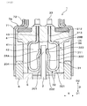
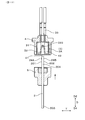
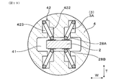
- FIG. 1 is a cross-sectional view showing a gas sensor according to a first embodiment.
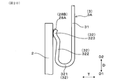
- FIG. 2 is an enlarged cross-sectional view showing the periphery of a spring terminal in the gas sensor according to the first embodiment.
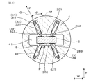
- 3 is a cross-sectional view taken along the line III-III in FIG. 1 and showing the periphery of a spring terminal in the gas sensor according to Embodiment 1.
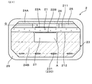
- FIG. 2 is a cross-sectional view showing a sensor element according to Embodiment 1.
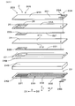
- FIG. 2 is an exploded perspective view showing a sensor element according to the first embodiment.
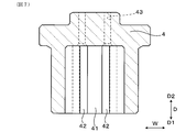
- FIG. 8 is a cross-sectional view taken along line VIII-VIII in FIG. 1, showing the periphery of the spring insulator according to the first embodiment.
- Sectional drawing equivalent to the III-III arrow of FIG. 1 which shows the insulator for spring in which the spring terminal was hold
- FIG. 1 Sectional drawing which shows the state which inserts a sensor element into the insertion hole of the insulator for springs by which the spring terminal was hold
- FIG. Sectional drawing equivalent to the III-III arrow of FIG. 1 which shows the insulator for spring in which the spring terminal was hold
- Sectional drawing equivalent to the III-III arrow of FIG. 1 which shows the state by which the sensor element was inserted in the insertion hole of the insulator for spring by which the spring terminal was hold
- Sectional drawing equivalent to the III-III arrow of FIG. 1 which shows the periphery of the spring terminal in the other gas sensor concerning Embodiment 1.
- Sectional drawing equivalent to the III-III arrow of FIG. 1 which shows the periphery of the spring terminal in a gas sensor concerning Embodiment 2.
- FIG. Explanatory drawing which shows the periphery of the terminal contact part in the outer surface of a sensor element concerning Embodiment 2 in the state seen from the thickness direction of a sensor element.
- Sectional drawing of the III-III arrow equivalent of FIG. 1 which shows the periphery of the spring terminal in the other gas sensor concerning Embodiment 2.
- FIG. Sectional drawing which shows the formation state of the holding groove of the insulator for springs concerning Embodiment 3, in the state seen from the thickness direction of the sensor element.
- FIG. 1 which shows the formation state of the holding groove of the insulator for springs concerning Embodiment 3.
- FIG. Sectional drawing equivalent to the III-III arrow of FIG. 1 which shows the formation state of the holding groove of the insulator for other springs concerning Embodiment 3.
- FIG. Explanatory drawing which shows the spring terminal which contacts the terminal contact part of a sensor element concerning Embodiment 4.
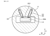
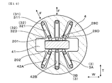
- the gas sensor 1 of the present embodiment includes a sensor element 2, a plurality of spring terminals 3, and a spring insulator 4.
- the sensor element 2 is for performing gas detection, and a plurality of terminal contact portions 28A and 28B are provided on the outer surfaces 201 and 202 of the proximal end portion 204 of the sensor element 2.
- the plurality of spring terminals 3 are configured by a bending wire.
- the spring insulator 4 has an insertion hole 41 into which the proximal end 204 of the sensor element 2 is inserted, and a plurality of holding grooves 42 communicated with the insertion hole 41.
- the spring terminal 3 is extended from the holding portion 31 held in the holding groove 42 and the holding portion 31 and is bent with respect to the holding portion 31 to contact the terminal contact portions 28A and 28B. And an arm portion 32.
- an arm portion for the holding portion 31 in the inclined spring terminal 3A which is at least one of the plurality of spring terminals 3
- the deflection direction F of 32 is inclined to the outer surface of the terminal contact portions 28A and 28B.
- All the spring terminals 3 in this embodiment are inclined spring terminals 3A. Further, the outer surfaces of the terminal contact portions 28A and 28B refer to surfaces parallel to the outer surfaces 201 and 202 of the sensor element 2.
- the gas sensor 1 of the present embodiment is disposed in the pipe 8 of the exhaust system of an internal combustion engine (engine) of a vehicle, and detects oxygen or specific gas components in the exhaust gas G flowing in the pipe 8 It is.
- the gas sensor 1 can be disposed upstream of the location where the catalyst is disposed in the pipe 8 and can also be disposed downstream of the location where the catalyst is disposed in the pipe 8.
- the pipe 8 in which the gas sensor 1 is disposed can also be a pipe on the suction side of a turbocharger that uses the exhaust gas G to increase the pressure of the air drawn by the internal combustion engine.
- the pipe 8 for disposing the gas sensor 1 can also be a pipe in an exhaust gas recirculation mechanism that recirculates a portion of the exhaust gas G exhausted from the internal combustion engine to the exhaust gas passage to the intake gas passage of the internal combustion engine.
- the vehicle equipped with the pipe 8 for disposing the gas sensor 1 may be a general vehicle that travels using fuel, a vehicle that performs idling stop when the vehicle is stopped, a hybrid vehicle, or the like.
- the gas sensor 1 is an oxygen concentration cell type that detects an electromotive force generated between a pair of electrodes, and a limiting current type that uses limiting current characteristics generated when a voltage is applied between a pair of electrodes. Can.
- the gas sensor 1 of the present embodiment is used for detecting an air-fuel ratio of an internal combustion engine obtained from an exhaust gas G as an application for detecting gas.
- the gas sensor 1 also has an application for detecting a specific gas component such as NOx, an application for detecting an oxygen concentration of exhaust gas G exhausted from an internal combustion engine, an air fuel ratio of the internal combustion engine determined from the exhaust gas G It can be used for applications such as detecting whether the fuel rich side or the fuel lean side with respect to the fuel ratio.
- the sensor element 2 has a plate-like solid electrolyte body 21 provided with a pair of electrodes 22A and 22B, and a heater 23 stacked on the solid electrolyte body 21.
- a detection electrode 22A exposed to the exhaust gas G is provided on the first main surface 211 of the solid electrolyte body 21, and a reference electrode 22B exposed to the atmosphere A is provided on the second main surface 212 of the solid electrolyte body 21. It is done.
- a gas chamber 26 into which the exhaust gas G is introduced is formed adjacent to the first main surface 211 of the solid electrolyte body 21 by the insulating layer 24A stacked on the first main surface 211.
- the detection electrode 22A is disposed in the gas chamber 26.
- An air duct 27 into which the air A is introduced is formed adjacent to the second major surface 212 of the solid electrolyte body 21 by the insulating layer 24B of the heater 23 stacked on the second major surface 212.
- the reference electrode 22B is disposed in the air duct 27.
- a part of the insulating layer 24A forming the gas chamber 26 is formed as a porous diffusion resistance layer 25 having a property of allowing the exhaust gas G to pass therethrough.
- the diffusion resistance layer 25 is for introducing the exhaust gas G into the gas chamber 26 at a constant diffusion rate.
- the gas sensor 1 of the present embodiment constitutes an air-fuel ratio sensor, and a voltage for expressing a limiting current characteristic is applied between the detection electrode 22A and the reference electrode 22B.
- the gas chamber 26 is formed at the distal end portion 203 of the sensor element 2, and the air duct 27 is formed from the distal end portion 203 of the sensor element 2 to the end surface of the proximal end portion 204.
- the atmosphere A entering the gas sensor 1 is introduced into the atmosphere duct 27.
- the heater 23 has a heating element 230 embedded in the insulating layer 24B.
- the heat generating body 230 has a heat generating portion 231 which generates heat by energization and a pair of lead portions 232 connected to the heat generating portion 231.
- the heat generating portion 231 is disposed at a position facing the detection electrode 22A and the reference electrode 22B, and the pair of lead portions 232 is arranged from the heat generating portion 231 to the proximal end portion 204 of the sensor element 2.
- the lead portion 221 connected to the detection electrode 22A and the lead portion 221 connected to the reference electrode 22B are disposed up to the base end portion 204 of the sensor element 2.
- the sensor element 2 is formed in a long shape.
- the insertion direction D of the sensor element 2 is a direction along the longitudinal direction of the sensor element 2.
- a detection portion 205 including a detection electrode 22A, a reference electrode 22B, a gas chamber 26, and a diffusion resistance layer 25 is formed at the tip portion 203 in the longitudinal direction of the sensor element 2.
- a plurality of terminal contact portions 28A and 28B are formed on the outer surfaces 201 and 202 of the proximal end portion 204 in the longitudinal direction of the sensor element 2.
- a porous protective layer 29 is provided on the outer periphery of the distal end portion 203 of the sensor element 2 so as to cover the detection unit 205.
- the direction in which the terminal contact portions 28A and 28B are disposed to face the spring terminals 3 is referred to as a thickness direction T, and a direction orthogonal to the insertion direction D and the thickness direction T is referred to as a width direction W.
- the thickness direction T is a direction in which the detection electrode 22A and the reference electrode 22B are provided opposite to the solid electrolyte body 21.
- the insertion direction D, the thickness direction T, and the width direction W indicate directions common to the sensor element 2, the spring insulator 4, the gas sensor 1, and the like.
- the insertion direction D indicates a direction toward both sides, and in FIGS. 1, 2, 5, 6, etc., the distal end side in the insertion direction D is indicated by D1, and the proximal end side in the insertion direction D is D2. Indicated.
- a plurality of terminal contact portions 28A, 28B at the proximal end portion 204 of the sensor element 2 are provided side by side in the width direction W orthogonal to the insertion direction D.
- the terminal contact portions 28A and 28B are provided on the outer surfaces 201 and 202 on both sides of the sensor element 2 in the thickness direction T.
- the plurality of terminal contact portions 28A and 28B are connected to two first terminal contact portions 28A respectively connected to the lead portion 221 of the detection electrode 22A and the lead portion 221 of the reference electrode 22B, and 2 connected to the lead portion 232 of the heating element 230. And two second terminal contact portions 28B.
- first terminal contact portions 28A are arranged side by side in the width direction W on the first outer surface 201 of the sensor element 2, and two second terminals on the second outer surface 202 of the sensor element 2.
- the contact portions 28B are arranged side by side in the width direction W.
- the first outer surface 201 is an outer surface located on the side where the solid electrolyte body 21 is provided with the detection electrode 22A
- the second outer surface 202 is an outer surface located on the side where the solid electrolyte body 21 is provided with a reference electrode 22B. is there.
- the insulating layer 24A is formed over the entire length in the longitudinal direction of the solid electrolyte body 21, and the first outer surface 201 and the second outer surface 202 of the sensor element 2 are of the insulating layers 24A and 24B. It is an outer surface.
- first outer surface 201 is the outer surface of solid electrolyte body 21. It may be
- Each of the electrodes 22A and 22B is made of a material containing a noble metal having catalytic activity to oxygen, and the solid electrolyte body 21 is made of a zirconia material having conductivity of oxygen ions.
- the insulating layers 24A and 24B and the diffusion resistance layer 25 are made of an alumina material as an insulating ceramic.
- an element insulator 5 for inserting and holding the sensor element 2 and a spring insulator 4 for holding a plurality of spring terminals 3 are disposed.
- the element insulator 5 is also referred to as an insulator, and is formed of an insulating ceramic such as alumina.
- the element insulator 5 is formed by compressing ceramic powder.
- an arrangement hole 51 penetrating in the insertion direction D is formed in order to arrange the sensor element 2.
- An intermediate position in the longitudinal direction of the sensor element 2 is inserted into the arrangement hole 51.
- the sensor element 2 is fixed to the element insulator 5 by a glass material 53 or the like filled in a recess 52 formed on the base end side of the arrangement hole 51.
- a housing hole 61 penetrating in the insertion direction D is formed in the housing 6.
- the element insulator 5 is disposed in the housing hole 61.
- a screw portion 62 and a hexagonal flange portion 63 for attaching the gas sensor 1 inserted into the attachment hole 81 provided in the pipe 8 to the pipe 8 are formed all around the outer periphery of the housing 6 There is.
- a wiring cover 7 ⁇ / b> A covering the spring insulator 4 is attached to the proximal end portion of the housing 6.
- the wiring cover 7A is configured of an inner circumferential cover 71 located on the inner circumferential side and an outer circumferential cover 72 overlapping the outer circumferential side of the inner circumferential cover 71.
- the outer peripheral cover 72 is formed with an introduction hole 721 into which the atmosphere A is introduced.
- a filter 73 formed of a porous sheet is disposed between the inner cover 71 and the outer cover 72 so as to cover the introduction hole 721.
- the filter 73 has a property of passing a gas but not a liquid.
- a rubber bush 74 for inserting and holding the lead wire 34 and closing the inside of the wiring cover 7A is disposed on the inner peripheral side of the outer peripheral cover 72.
- the air A introduced into the wiring cover 7A via the introduction hole 721 and the filter 73 is introduced into the air duct 27 from the end face of the sensor element 2 on the proximal end side.
- An element cover 7 ⁇ / b> B that covers the tip end portion of the sensor element 2 is attached to the tip end portion of the housing 6.
- the exhaust gas G passing through the piping 8 of the exhaust system is introduced to the detection part 205 of the sensor element 2 and is circulated for circulating the inside and the outside of the element cover 7B. Holes 75 are formed.
- the spring insulator 4 is also referred to as an insulator, and is formed of an insulating ceramic such as alumina.
- the spring insulator 4 is formed by compressing ceramic powder.
- the spring insulator 4 is disposed so as to overlap the proximal end side of the element insulator 5 in the insertion direction D, and accommodates the proximal end portion 204 of the sensor element 2.
- the insertion hole 41 of the spring insulator 4 is a bottomed hole which does not penetrate the spring insulator 4 from the end face on the tip side where the sensor element 2 is inserted. It is formed as.
- the insertion hole 41 is formed at a central position in a plane orthogonal to the insertion direction D.
- the insertion hole 41 is formed as a hole of a substantially square cross section in accordance with the shape of the sensor element 2 having a substantially square cross section.
- a plurality of through holes 43 into which the end portions of the holding portions 31 of the plurality of spring terminals 3 are inserted are formed in the base end portion of the spring insulator 4 There is.
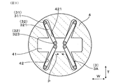
- the holding groove 42 of the spring insulator 4 is formed from the end face of the tip end side of the spring insulator 4 and is communicated with the insertion hole 41 in the thickness direction T.
- the holding groove 42 is formed to be inclined with respect to the thickness direction T in order to arrange the inclined spring terminal 3A in a state in which the inclined spring terminal 3A is inclined with respect to the thickness direction T.
- a part of the holding part 31 and a part of the arm part 32 are arranged.
- the outer peripheral surface as a side surface parallel to the insertion direction D of the insulator 4 for spring has a circular cross-sectional shape. As shown in FIG. 7, the holding groove 42 is continuously formed from the end surface on the tip end side of the spring insulator 4 to the base end side.
- the spring insulator 4 is provided with four inclined spring terminals 3A that individually contact the two first terminal contact portions 28A and the two second terminal contact portions 28B. Is held.
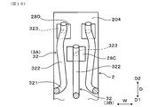
- the arm portion 32 of the inclined spring terminal 3A is folded back from the holding portion 31 and is opposed to the holding portion 31 in the bending direction F.
- the arm portion 32 is formed to face the holding portion 31 so that the spring characteristic of the arm portion 32 can be developed so that the arm portion 32 can bend (elastically deform) with respect to the holding portion 31. It will be easier.
- the bending direction F of the arm portion 32 in the present embodiment is a direction in which the holding portion 31 and the arm portion 32 face each other.
- the holding portion 31 includes a main body portion 311 disposed at an outer peripheral end of the holding groove 42, an extending portion 312 inserted into the through hole 43, a main body portion 311 and an extending portion And a connection portion 313 connecting the connection portion 312.
- the main body portion 311 and the extension portion 312 are formed to be offset in a direction perpendicular to the insertion direction D in parallel with each other.
- the arm portion 32 includes a curved portion 321 connected to the main portion 311 of the holding portion 31, a straight portion 322 connected to the curved portion 321, and a contact portion 323 provided on the straight portion 322 and contacting the terminal contact portions 28A and 28B. Have.
- the contact portion 323 is formed in a curved shape.
- the arm portion 32 is bent so that the linear portion 322 and the contact portion 323 approach the main body portion 311 of the holding portion 31 by mainly elastically deforming the curved portion 321 so as to reduce the radius of curvature.
- the arm portion 32 is also bent when the entire arm portion 32 except the curved portion 321 is warped.
- the terminal fitting 33 from the base end side of the spring insulator 4 Is attached.
- a lead 34 connected to a control device or the like outside the gas sensor 1 is attached to the terminal fitting 33.
- the spring terminal 3 of the present embodiment is formed of a round wire (steel wire) having a circular cross section and a wire diameter in the range of ⁇ 0.4 to 0.7 mm.
- the holding portion 31 and the arm portion 32 are formed by bending a round wire.
- a round wire it is possible to secure the strength and to minimize the width of the wire forming the spring terminal 3 as much as possible.
- the space occupied by the plurality of spring terminals 3 in the spring insulator 4 can be reduced, and the miniaturization of the spring insulator 4 and, in addition, the gas sensor 1 can be achieved. .
- the gap S between the spring terminal 3 and the holding groove 42 of the spring insulator 4 in which the spring terminal 3 is disposed is The amount of displacement of the spring terminal 3 in the width direction W in the holding groove 42 increases. Therefore, the width in the width direction W of the terminal contact portions 28A and 28B in the sensor element 2 needs to be increased, which causes the miniaturization of the sensor element 2 to be hindered.
- the width of the holding groove 42 of the spring insulator 4 in which the spring terminal 3 is disposed is preferably 0.7 mm or more from the viewpoint of securing the strength of the mold for molding the spring insulator 4.
- the cross-sectional shape of the spring terminal 3 may be a flat shape, an elliptical shape, an angular shape including a quadrilateral shape, or the like.
- the aspect ratio which is the ratio of the length of the long diameter portion (long side portion) to the length of the short diameter portion (short side portion) in the cross section of the spring terminal 3 is in the range of 1: 1 to 1: 2. You can do so.
- the inclined spring terminals 3 ⁇ / b> A are arranged side by side in the width direction W, and are arranged at positions facing each other via the sensor element 2. Further, the inclined spring terminals 3A are arranged in a pair in the width direction W on both sides in the thickness direction T of the sensor element 2. Two inclined spring terminals 3A are provided in the width direction W opposite to the first outer surface 201, corresponding to the two first terminal contact portions 28A provided on the first outer surface 201 of the proximal end portion 204 of the sensor element 2. They are arranged side by side.
- the inclined spring terminals 3A are opposed to the second outer surface 202 in the width direction W corresponding to the two second terminal contact portions 28B provided on the second outer surface 202 of the proximal end portion 204 of the sensor element 2. Two are arranged side by side. The two inclined spring terminals 3A disposed opposite to the first outer surface 201 and the two inclined spring terminals 3A disposed opposite to the second outer surface 202 face each other via the sensor element 2.
- each of the inclined spring terminals 3A inclines is such that the arm portion 32 is positioned closer to the center in the width direction W of the sensor element 2 than the holding portion 31.
- the four inclined spring terminals 3A are arranged to be inclined with respect to the thickness direction T of the sensor element 2 in a state close to the X shape.
- the inclined spring terminals 3A face each other through the sensor element 2 in the thickness direction T
- the contact portions 323 of the arm portions 32 of the inclined spring terminals 3A facing each other come into contact with each other.
- the arm portions 32 are positioned on the center side in the width direction W of the sensor element 2 with respect to the holding portion 31 so that the contact portions 323 of the arm portions 32 of the inclined spring terminals 3A opposed to each other are In any case, the position shifts to the center side in the width direction W. Therefore, the arm portions 32 of the inclined spring terminals 3A are prevented from being displaced to different sides in the width direction W.
- the contact portion 323 of the arm portion 32 is prevented from being displaced outward in the width direction W from the terminal contact portions 28A and 28B, and is prevented from coming out in the width direction W of the sensor element 2.
- the direction in which each contact portion 323 of the arm portion 32 is displaced is indicated by an arrow P.
- each inclined spring terminal 3A since the arm portion 32 of each inclined spring terminal 3A is located on the center side of the holding portion 31 in the width direction W of the sensor element 2, in the spring insulator 4, the plurality of inclined spring terminals 3A are as radial as possible. It can be placed close to Thus, the distance between the holding portions 31 of the pair of inclined spring terminals 3A aligned in the width direction W can be increased. Therefore, interference between the terminal fittings 33 connected to the inclined spring terminals 3A and the lead wires 34 connected to the inclined spring terminals 3A through the terminal fittings 33 can be easily avoided.
- the arm portions 32 of the respective inclined spring terminals 3A in the state of being in contact with the terminal contact portions 28A, 28B of the sensor element 2 are terminals compared to the state before contacting the terminal contact portions 28A, 28B. It is bent in a state in which the inclination angle ⁇ of the central axis O along the bending direction F with respect to a perpendicular M perpendicular to the outer surface of the contact portions 28A and 28B is increased.
- the central axis O refers to an imaginary line passing through the center of the cross section of the arm portion 32 when viewed in the insertion direction D.
- the arm portion 32 of the inclined spring terminal 3A contacts the side surface 421 on the center side in the width direction W of the holding groove 42, and the position relative to the outer surface of the terminal contact portions 28A and 28B is fixed. .
- the width of the holding groove 42 of the spring insulator 4 is larger than the wire diameter of the spring terminal 3.
- a gap S is formed between the holding groove 42 and the spring terminal 3.
- the inclination angle ⁇ between a perpendicular M and the outer surface of 28 B is in the range of 5 to 45 °. If the inclination angle ⁇ is less than 5 °, it is difficult to obtain the effect of the bending direction F of the arm portion 32 of the inclined spring terminal 3A being inclined with respect to the outer surfaces of the terminal contact portions 28A and 28B.
- the two inclined spring terminals 3A aligned in the width direction W are two inclinations aligned in the width direction W
- the arm portions 32 of the spring terminals 3A are disposed so as not to be in contact with each other at a position and an inclination angle.
- the insertability of the sensor element 2 into the insertion hole 41 is deteriorated.
- the contact state of the spring terminal 3 with the terminal contact portions 28A and 28B on the outer surfaces 201 and 202 of the sensor element 2 is kept good It is devising. Specifically, a spring restoring force to be applied to the arm portion 32 of the spring terminal 3 is applied to the outer surfaces of the terminal contact portions 28A and 28B in a state of being inclined in the thickness direction T. And the contact part 323 of the arm part 32 forms the state which can be displaced only on the center side of the width direction W of the outer surface of terminal contact part 28A, 28B.
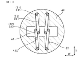
- the arm portions 32 of the spring terminals 3X contact each other in the thickness direction T as a comparative embodiment, the spring terminals 3X are in contact with the spring restoring force along the thickness direction T.
- the arm portions 32 may be misaligned to different sides in the width direction W and may pass each other in the width direction W because they are formed of round wire rods.
- the spring insulator is indicated by reference numeral 4X
- the holding groove is indicated by reference numeral 42X.
- each inclined spring terminal 3A contacts the side surface 421 on the center side in the width direction W of the holding groove 42 of the spring insulator 4.
- the direction and amount of displacement of the contact portion 323 of the arm portion 32 is regulated, and the position where the contact portion 323 of the arm portion 32 contacts the outer surfaces of the terminal contact portions 28A and 28B is determined. Therefore, the contact position of the arm portion 32 with respect to the terminal contact portions 28A and 28B is fixed, and a contact failure can be less likely to occur between the arm portion 32 and the terminal contact portions 28A and 28B.
- the state of the inclined spring terminal 3A can be maintained properly. So, according to the gas sensor 1 of this form, the state of the electrical connection between the spring terminal 3 and the sensor element 2 can be made favorable.
- the inclination spring terminal 3A which contacts the 2nd terminal contact part 28B and the 2nd terminal contact part 28B becomes unnecessary.
- the first terminal contact portion 28A is formed on the first outer surface 201 of the sensor element 2
- the inclined spring terminal 3A is the first terminal contact of the first outer surface 201 of the sensor element 2. Only two contacting portions 28A can be used.
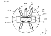
- Second Embodiment shows the case where the number of holding the spring terminals 3 in the spring insulator 4 is six. As shown in FIG. 14, in addition to the four inclined spring terminals 3A, the two vertical spring terminals 3B are held by the spring insulator 4 of the present embodiment.
- the vertical spring terminals 3 ⁇ / b> B are the spring terminals 3 other than the inclined spring terminals 3 ⁇ / b> A among the plurality of spring terminals 3 held by the spring insulator 4.
- the vertical spring terminals 3B are disposed between the pair of inclined spring terminals 3A aligned in the width direction W such that the bending direction F of the arm portion 32 is perpendicular to the outer surfaces of the terminal contact portions 28A and 28B.
- a holding groove 42 A for the inclined spring terminal 3 A inclined in the thickness direction T and a holding groove 42 B for the vertical spring terminal 3 B parallel to the thickness direction T are formed.
- the number of the electrodes provided in the sensor element 2 is four, and the number of the lead portions 232 of the heating element 230 of the heater 23 is two, so that a total of six spring terminals 3 are used.
- the gas sensor 1 of the present embodiment can be, for example, a NOx sensor that detects the concentration of a specific gas component such as NOx (nitrogen oxide).
- a pump electrode provided on the first major surface 211 of the solid electrolyte body 21 for discharging oxygen in the exhaust gas G in the gas chamber 26 and residual oxygen of the exhaust gas G in the gas chamber 26
- a monitor electrode provided on the first main surface 211 of the solid electrolyte body 21 to detect the concentration, and a first main surface 211 of the solid electrolyte body 21 to detect the NOx concentration of the exhaust gas G in the gas chamber 26
- Four electrodes of the sensor electrode and the reference electrode exposed to the atmosphere A provided on the second major surface 212 of the solid electrolyte body 21 are used.
- a heater 23 is stacked on the sensor element 2.
- three terminal contact portions 28C and 28D are formed on the first outer surface 201 and the second outer surface 202 of the sensor element 2, respectively.
- the first outer surface 201 is formed with three terminal contact portions 28C and 28D connected to the lead portions 221 of the pump electrode, the monitor electrode and the sensor electrode.
- On the second outer surface 202 three terminal contact portions 28C and 28D connected to the lead portion 221 of the reference electrode and the lead portion 232 of the heating element 230 of the heater 23 are formed.
- the three terminal contact portions 28C and 28D formed on the outer surfaces 201 and 202 of the sensor element 2 two proximal ends formed in the width direction W on the base end side of the proximal end portion 204 of the sensor element 2
- the arm portions 32 of the two inclined spring terminals 3A aligned in the width direction W are in contact with the two proximal terminal contact portions 28D.
- the arm portion 32 of the vertical spring terminal 3B is in contact with the tip side terminal contact portion 28C.
- the formation width in the width direction W of the distal side terminal contact portion 28C in contact with the vertical spring terminal 3B is larger than the formation width in the width direction W of the proximal terminal contact portion 28D.
- positional deviation of the arm portion 32 of the vertical spring terminal 3 ⁇ / b> B to any side in the width direction W of the sensor element 2 can be tolerated.
- the correspondence relationship between the pump electrode, the monitor electrode, the sensor electrode, the reference electrode, the heating element 230, and the inclined spring terminal 3A and the vertical spring terminal 3B can be any correspondence relationship.
- the vertical spring terminals 3B are disposed between the pair of inclined spring terminals 3A according to the increase in the number of electrodes used for the sensor element 2.
- formation width of tip end side terminal contact part 28C which vertical spring terminal 3B contacts width direction W is larger than formation width of width end W of proximal end terminal contact part 28D which inclination spring terminal 3A contacts.
- the heater 23 When the heater 23 is not stacked on the sensor element 2 of the NOx sensor, four electrodes of the pump electrode, the monitor electrode, the sensor electrode, and the reference electrode are provided on the first outer surface 201 and the second outer surface 202 of the sensor element 2. It can be made to respond
- Embodiment 3 shows a modification of the holding groove 42 in the spring insulator 4.
- the holding groove 42 is not formed continuously from the end face of the tip end side of the spring insulator 4 to the base end side as shown in FIG. 17, but from the recess 44 formed in the tip side portion of the spring insulator 4 It may be formed toward the proximal side.
- the holding groove 42 can be formed in a step-like shape in the state seen from the insertion direction D as shown in FIGS. 18 and 19 in addition to being formed linearly in the state seen from the insertion direction D .
- the step-like holding groove 42 is formed such that the inclined spring terminal 3A is disposed to be inclined with respect to the thickness direction T of the sensor element 2.
- the holding portion 31 of the inclined spring terminal 3A is disposed at an outer corner of the stepped holding groove 42 in the width direction W.
- the arm portion 32 of the inclined spring terminal 3A is arranged from the holding portion 31 toward the center side in the width direction W.
- the width in the width direction W of the portion 422 located on the center side in the thickness direction T in the holding groove 42 is the width in the width direction W of the portion 423 located outside the thickness direction T in the holding groove 42. An example smaller than this is shown.
- the portion 422 located on the center side in the thickness direction T in the holding groove 42 is formed on the center side in the width direction W than the portion 423 located on the outer side in the thickness direction T in the holding groove 42.
- the inclined spring terminals 3A can be inclined with respect to the outer surfaces of the terminal contact portions 28A and 28B.
- the present embodiment shows a modification of the shape of the spring terminal 3.
- the holding portion 31 of the spring terminal 3 can be formed in a straight line parallel to the insertion direction D as shown in FIG. 20, besides being bent and formed so that the position in the bending direction F is offset.
- the arm portion 32 extends from the end portion on the tip end side of the holding portion 31 in the insertion direction D to the tip end side, as shown in FIG. It can also be formed in the Moreover, although it is against the miniaturization, as shown in FIG. 22, the arm 32 is folded back from the end on the distal end side of the holding portion 31 in the insertion direction D to the proximal end and is further folded back to the distal end. It can also be formed into
- FIG. 20 to 22 show the spring terminal 3 disposed on the outer surface on one side of the sensor element 2.
- FIG. The spring terminals 3 may be disposed on the outer surfaces on both sides of the sensor element 2.
- the other configuration, effects, and the like of the gas sensor 1 of the present embodiment are the same as those of the first embodiment.
- the constituent elements indicated by the same reference numerals as the reference numerals in the first embodiment are the same as those in the first embodiment.
- the number of spring terminals 3 used in the gas sensor 1 can be appropriately changed in accordance with the number of electrodes provided in the sensor element 2.
- two solid electrolyte bodies 21 may be used in the gas sensor 1, and the solid electrolyte body 21 in which the pump electrode is formed and the solid electrolyte body 21 in which the monitor electrode and the sensor electrode are formed may be different.
- the structure shown in each embodiment can also be applied to the sensor element 2 in which the air duct 27 is not formed.
Landscapes
- Chemical & Material Sciences (AREA)
- Life Sciences & Earth Sciences (AREA)
- Health & Medical Sciences (AREA)
- Pathology (AREA)
- General Physics & Mathematics (AREA)
- Immunology (AREA)
- Physics & Mathematics (AREA)
- Analytical Chemistry (AREA)
- Biochemistry (AREA)
- General Health & Medical Sciences (AREA)
- Chemical Kinetics & Catalysis (AREA)
- Electrochemistry (AREA)
- Molecular Biology (AREA)
- Engineering & Computer Science (AREA)
- Combustion & Propulsion (AREA)
- Food Science & Technology (AREA)
- Medicinal Chemistry (AREA)
- Measuring Oxygen Concentration In Cells (AREA)
Priority Applications (3)
| Application Number | Priority Date | Filing Date | Title |
|---|---|---|---|
| DE112018004919.1T DE112018004919T5 (de) | 2017-08-31 | 2018-08-27 | Gassensor |
| CN201880055704.5A CN111051872B (zh) | 2017-08-31 | 2018-08-27 | 气体传感器 |
| US16/799,998 US12061164B2 (en) | 2017-08-31 | 2020-02-25 | Gas sensor |
Applications Claiming Priority (2)
| Application Number | Priority Date | Filing Date | Title |
|---|---|---|---|
| JP2017167558A JP6747407B2 (ja) | 2017-08-31 | 2017-08-31 | ガスセンサ |
| JP2017-167558 | 2017-08-31 |
Related Child Applications (1)
| Application Number | Title | Priority Date | Filing Date |
|---|---|---|---|
| US16/799,998 Continuation US12061164B2 (en) | 2017-08-31 | 2020-02-25 | Gas sensor |
Publications (1)
| Publication Number | Publication Date |
|---|---|
| WO2019044746A1 true WO2019044746A1 (ja) | 2019-03-07 |
Family
ID=65527508
Family Applications (1)
| Application Number | Title | Priority Date | Filing Date |
|---|---|---|---|
| PCT/JP2018/031518 Ceased WO2019044746A1 (ja) | 2017-08-31 | 2018-08-27 | ガスセンサ |
Country Status (5)
| Country | Link |
|---|---|
| US (1) | US12061164B2 (enExample) |
| JP (1) | JP6747407B2 (enExample) |
| CN (1) | CN111051872B (enExample) |
| DE (1) | DE112018004919T5 (enExample) |
| WO (1) | WO2019044746A1 (enExample) |
Cited By (3)
| Publication number | Priority date | Publication date | Assignee | Title |
|---|---|---|---|---|
| JP2021032785A (ja) * | 2019-08-28 | 2021-03-01 | 日本碍子株式会社 | ガスセンサ |
| WO2022024583A1 (ja) * | 2020-07-31 | 2022-02-03 | 株式会社デンソー | ガスセンサ |
| US11594481B2 (en) * | 2020-08-27 | 2023-02-28 | Infineon Technologies Ag | Package, method for forming a package, carrier tape, chip card and method for forming a carrier tape |
Families Citing this family (2)
| Publication number | Priority date | Publication date | Assignee | Title |
|---|---|---|---|---|
| JP7349300B2 (ja) * | 2019-09-17 | 2023-09-22 | 日本碍子株式会社 | ガスセンサ |
| JP7489283B2 (ja) * | 2020-10-06 | 2024-05-23 | 日本特殊陶業株式会社 | ガスセンサ |
Citations (5)
| Publication number | Priority date | Publication date | Assignee | Title |
|---|---|---|---|---|
| JPH09512912A (ja) * | 1994-05-05 | 1997-12-22 | ロト テヒニク ゲーエムベーハー ウント コー フォルシュンク フュア アウトモビル ウント ウンベルトテヒニク | ガスセンサ |
| JP2001188060A (ja) * | 1999-10-19 | 2001-07-10 | Denso Corp | ガスセンサ |
| JP2001343356A (ja) * | 2000-03-30 | 2001-12-14 | Denso Corp | ガスセンサ |
| JP2006337096A (ja) * | 2005-05-31 | 2006-12-14 | Ngk Spark Plug Co Ltd | センサ |
| JP2012230076A (ja) * | 2011-04-27 | 2012-11-22 | Ngk Spark Plug Co Ltd | センサ |
Family Cites Families (9)
| Publication number | Priority date | Publication date | Assignee | Title |
|---|---|---|---|---|
| US6477887B1 (en) * | 1999-08-30 | 2002-11-12 | Masato Ozawa | Gas sensor having pre-stressed terminal for contact with inserted sensor element |
| JP2004264262A (ja) * | 2003-03-04 | 2004-09-24 | Denso Corp | セラミック素子と摺動端子との摺動接触構造 |
| JP2007155697A (ja) | 2005-11-10 | 2007-06-21 | Denso Corp | ガスセンサ |
| JP5509234B2 (ja) * | 2012-02-29 | 2014-06-04 | 日本特殊陶業株式会社 | ガスセンサ |
| JP5682637B2 (ja) | 2012-05-17 | 2015-03-11 | 株式会社デンソー | ガスセンサ |
| JP2015145831A (ja) * | 2014-02-03 | 2015-08-13 | 株式会社デンソー | ガスセンサ |
| JP6331891B2 (ja) * | 2014-08-29 | 2018-05-30 | 株式会社デンソー | ガスセンサ |
| JP6500769B2 (ja) * | 2015-12-21 | 2019-04-17 | 株式会社デンソー | センサ |
| JP2017167558A (ja) | 2017-05-22 | 2017-09-21 | オプリンク コミュニケーションズ エルエルシー | Memsファイバ光スイッチ |
-
2017
- 2017-08-31 JP JP2017167558A patent/JP6747407B2/ja active Active
-
2018
- 2018-08-27 WO PCT/JP2018/031518 patent/WO2019044746A1/ja not_active Ceased
- 2018-08-27 DE DE112018004919.1T patent/DE112018004919T5/de active Pending
- 2018-08-27 CN CN201880055704.5A patent/CN111051872B/zh active Active
-
2020
- 2020-02-25 US US16/799,998 patent/US12061164B2/en active Active
Patent Citations (5)
| Publication number | Priority date | Publication date | Assignee | Title |
|---|---|---|---|---|
| JPH09512912A (ja) * | 1994-05-05 | 1997-12-22 | ロト テヒニク ゲーエムベーハー ウント コー フォルシュンク フュア アウトモビル ウント ウンベルトテヒニク | ガスセンサ |
| JP2001188060A (ja) * | 1999-10-19 | 2001-07-10 | Denso Corp | ガスセンサ |
| JP2001343356A (ja) * | 2000-03-30 | 2001-12-14 | Denso Corp | ガスセンサ |
| JP2006337096A (ja) * | 2005-05-31 | 2006-12-14 | Ngk Spark Plug Co Ltd | センサ |
| JP2012230076A (ja) * | 2011-04-27 | 2012-11-22 | Ngk Spark Plug Co Ltd | センサ |
Cited By (5)
| Publication number | Priority date | Publication date | Assignee | Title |
|---|---|---|---|---|
| JP2021032785A (ja) * | 2019-08-28 | 2021-03-01 | 日本碍子株式会社 | ガスセンサ |
| US11585781B2 (en) | 2019-08-28 | 2023-02-21 | Ngk Insulators, Ltd. | Gas sensor |
| JP7242478B2 (ja) | 2019-08-28 | 2023-03-20 | 日本碍子株式会社 | ガスセンサ |
| WO2022024583A1 (ja) * | 2020-07-31 | 2022-02-03 | 株式会社デンソー | ガスセンサ |
| US11594481B2 (en) * | 2020-08-27 | 2023-02-28 | Infineon Technologies Ag | Package, method for forming a package, carrier tape, chip card and method for forming a carrier tape |
Also Published As
| Publication number | Publication date |
|---|---|
| US20200191743A1 (en) | 2020-06-18 |
| CN111051872A (zh) | 2020-04-21 |
| JP6747407B2 (ja) | 2020-08-26 |
| DE112018004919T5 (de) | 2020-07-02 |
| CN111051872B (zh) | 2023-04-04 |
| JP2019045260A (ja) | 2019-03-22 |
| US12061164B2 (en) | 2024-08-13 |
Similar Documents
| Publication | Publication Date | Title |
|---|---|---|
| WO2019044746A1 (ja) | ガスセンサ | |
| US8118985B2 (en) | Gas sensor | |
| JP4474752B2 (ja) | ガスセンサ | |
| US10514356B2 (en) | Gas sensor | |
| JP2003043004A (ja) | ガスセンサ | |
| US10451583B2 (en) | Gas sensor | |
| US20220065809A1 (en) | Gas sensor | |
| EP1394536A1 (en) | Gas sensor and structure of electric connector | |
| JP4461585B2 (ja) | ガスセンサ | |
| US10502704B2 (en) | Gas sensor provided with flange portion of cover thereof | |
| US10481122B2 (en) | Gas sensor element and gas sensor | |
| JP7432542B2 (ja) | ガスセンサ | |
| JP7186131B2 (ja) | ガスセンサ | |
| JP4527626B2 (ja) | ガスセンサ素子及びガスセンサ | |
| JP5836350B2 (ja) | ガスセンサ | |
| JP5886221B2 (ja) | ガスセンサ | |
| JP6438851B2 (ja) | ガスセンサ素子及びガスセンサ | |
| US12422398B2 (en) | Gas sensor | |
| JP6406161B2 (ja) | ガスセンサ | |
| JP2023157507A (ja) | ガスセンサ | |
| JP3861775B2 (ja) | ガスセンサ | |
| CN117147656A (zh) | 气体传感器 | |
| JP2022064065A (ja) | ガスセンサ |
Legal Events
| Date | Code | Title | Description |
|---|---|---|---|
| 121 | Ep: the epo has been informed by wipo that ep was designated in this application |
Ref document number: 18850457 Country of ref document: EP Kind code of ref document: A1 |
|
| 122 | Ep: pct application non-entry in european phase |
Ref document number: 18850457 Country of ref document: EP Kind code of ref document: A1 |