WO2019044746A1 - ガスセンサ - Google Patents
ガスセンサ Download PDFInfo
- Publication number
- WO2019044746A1 WO2019044746A1 PCT/JP2018/031518 JP2018031518W WO2019044746A1 WO 2019044746 A1 WO2019044746 A1 WO 2019044746A1 JP 2018031518 W JP2018031518 W JP 2018031518W WO 2019044746 A1 WO2019044746 A1 WO 2019044746A1
- Authority
- WO
- WIPO (PCT)
- Prior art keywords
- spring
- terminal
- sensor element
- terminal contact
- gas sensor
- Prior art date
Links
Images


Classifications
-
- G—PHYSICS
- G01—MEASURING; TESTING
- G01N—INVESTIGATING OR ANALYSING MATERIALS BY DETERMINING THEIR CHEMICAL OR PHYSICAL PROPERTIES
- G01N33/00—Investigating or analysing materials by specific methods not covered by groups G01N1/00 - G01N31/00
- G01N33/0004—Gaseous mixtures, e.g. polluted air
- G01N33/0009—General constructional details of gas analysers, e.g. portable test equipment
- G01N33/0027—General constructional details of gas analysers, e.g. portable test equipment concerning the detector
- G01N33/0036—Specially adapted to detect a particular component
-
- G—PHYSICS
- G01—MEASURING; TESTING
- G01N—INVESTIGATING OR ANALYSING MATERIALS BY DETERMINING THEIR CHEMICAL OR PHYSICAL PROPERTIES
- G01N27/00—Investigating or analysing materials by the use of electric, electrochemical, or magnetic means
- G01N27/26—Investigating or analysing materials by the use of electric, electrochemical, or magnetic means by investigating electrochemical variables; by using electrolysis or electrophoresis
- G01N27/403—Cells and electrode assemblies
- G01N27/406—Cells and probes with solid electrolytes
- G01N27/4062—Electrical connectors associated therewith
-
- G—PHYSICS
- G01—MEASURING; TESTING
- G01N—INVESTIGATING OR ANALYSING MATERIALS BY DETERMINING THEIR CHEMICAL OR PHYSICAL PROPERTIES
- G01N27/00—Investigating or analysing materials by the use of electric, electrochemical, or magnetic means
- G01N27/26—Investigating or analysing materials by the use of electric, electrochemical, or magnetic means by investigating electrochemical variables; by using electrolysis or electrophoresis
- G01N27/403—Cells and electrode assemblies
- G01N27/406—Cells and probes with solid electrolytes
- G01N27/4067—Means for heating or controlling the temperature of the solid electrolyte
-
- G—PHYSICS
- G01—MEASURING; TESTING
- G01N—INVESTIGATING OR ANALYSING MATERIALS BY DETERMINING THEIR CHEMICAL OR PHYSICAL PROPERTIES
- G01N27/00—Investigating or analysing materials by the use of electric, electrochemical, or magnetic means
- G01N27/26—Investigating or analysing materials by the use of electric, electrochemical, or magnetic means by investigating electrochemical variables; by using electrolysis or electrophoresis
- G01N27/403—Cells and electrode assemblies
- G01N27/406—Cells and probes with solid electrolytes
- G01N27/407—Cells and probes with solid electrolytes for investigating or analysing gases
- G01N27/409—Oxygen concentration cells
-
- H—ELECTRICITY
- H01—ELECTRIC ELEMENTS
- H01R—ELECTRICALLY-CONDUCTIVE CONNECTIONS; STRUCTURAL ASSOCIATIONS OF A PLURALITY OF MUTUALLY-INSULATED ELECTRICAL CONNECTING ELEMENTS; COUPLING DEVICES; CURRENT COLLECTORS
- H01R13/00—Details of coupling devices of the kinds covered by groups H01R12/70 or H01R24/00 - H01R33/00
- H01R13/02—Contact members
- H01R13/22—Contacts for co-operating by abutting
- H01R13/24—Contacts for co-operating by abutting resilient; resiliently-mounted
- H01R13/2407—Contacts for co-operating by abutting resilient; resiliently-mounted characterized by the resilient means
-
- H—ELECTRICITY
- H01—ELECTRIC ELEMENTS
- H01R—ELECTRICALLY-CONDUCTIVE CONNECTIONS; STRUCTURAL ASSOCIATIONS OF A PLURALITY OF MUTUALLY-INSULATED ELECTRICAL CONNECTING ELEMENTS; COUPLING DEVICES; CURRENT COLLECTORS
- H01R13/00—Details of coupling devices of the kinds covered by groups H01R12/70 or H01R24/00 - H01R33/00
- H01R13/02—Contact members
- H01R13/26—Pin or blade contacts for sliding co-operation on one side only
-
- H—ELECTRICITY
- H01—ELECTRIC ELEMENTS
- H01R—ELECTRICALLY-CONDUCTIVE CONNECTIONS; STRUCTURAL ASSOCIATIONS OF A PLURALITY OF MUTUALLY-INSULATED ELECTRICAL CONNECTING ELEMENTS; COUPLING DEVICES; CURRENT COLLECTORS
- H01R2201/00—Connectors or connections adapted for particular applications
- H01R2201/20—Connectors or connections adapted for particular applications for testing or measuring purposes
Definitions
- the present disclosure relates to a gas sensor having a structure in which a sensor element contacts a spring terminal held by an insulator.
- the gas sensor is used to detect the concentration of oxygen, a specific gas component, and the like in the exhaust gas exhausted from the internal combustion engine.
- sensor elements of the gas sensor there is a laminated type in which an insulating layer forming a gas chamber or the like into which exhaust gas is introduced is stacked on a plate-like solid electrolyte body. The end of the stacked type sensor element is accommodated in the insertion hole of the insulator and electrically connected to the spring terminal held in the holding groove of the insulator.
- the spring terminal has a holding portion, and an arm portion that bends relative to the holding portion and contacts the sensor element.
- the spring terminals are disposed on both sides of the sensor element, and sandwich the sensor element from both sides when the arm portion contacts and bends the sensor element.
- the terminal contact part connected with the electrode provided in the solid electrolyte body is arrange
- Patent Document 1 discloses a gas sensor using a spring terminal made of a wire.
- the end of the sensor element is inserted into the insertion hole of the insulator in which the spring terminal is held in each of the plurality of holding grooves.
- the arm portion of the spring terminal disclosed in Patent Document 1 or the like vertically contacts the terminal contact portion on the outer surface of the sensor element and bends with respect to the holding portion.
- the bending direction of the arm portion is perpendicular to the outer surface of the terminal contact portion as the thickness direction of the sensor element.
- the arm portion when the arm portion slides on the outer surface of the terminal contact portion when the arm portion bends, the arm portion may be displaced to the left or right with respect to the electrode contact portion.
- the contact position of the arm portion with respect to the terminal contact portion is not fixed, and there is a possibility that contact failure may occur between the arm portion and the terminal contact portion. Therefore, in order to improve the state of the electrical connection between the spring terminal and the sensor element, further measures are required.
- the present disclosure has been obtained in an attempt to provide a gas sensor that can improve the state of the electrical connection between the spring terminal and the sensor element.
- One aspect of the present disclosure is a sensor element in which a plurality of terminal contacts are provided on the outer surface of a proximal end for performing gas detection; A plurality of spring terminals constituted by bending wires; A gas sensor comprising: an insertion hole into which the base end of the sensor element is inserted; and an insulator having a plurality of holding grooves communicated with the insertion hole,
- the spring terminal includes a holding portion held in the holding groove, and an arm portion extended from the holding portion and bent with respect to the holding portion to contact the terminal contact portion.
- the bending direction of the arm portion with respect to the holding portion in the inclined spring terminal which is at least one of the plurality of spring terminals is the terminal contact In the gas sensor, which is inclined to the outer surface of the part.
- a device is devised in the bending direction of the arm portion of the spring terminal held by the insulator. Specifically, when viewed from the insertion direction of the sensor element in the insertion hole, the bending direction of the arm portion with respect to the holding portion in at least one of the plurality of spring terminals is relative to the outer surface of the terminal contact portion. It is inclined.
- an arm part bends in the direction which inclines to the external surface of a terminal contact portion.
- the direction in which the arm portion slides is restricted. Specifically, the arm portion slides in a direction in which the inclination angle with respect to the perpendicular of the outer surface of the terminal contact portion increases.
- the contact position of the arm with respect to the terminal contact portion is fixed, and contact failure can be less likely to occur between the arm and the terminal contact portion. So, according to the gas sensor of the said one aspect, the state of the electrical connection between a spring terminal and a sensor element can be made favorable.
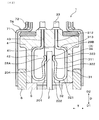
- FIG. 1 is a cross-sectional view showing a gas sensor according to a first embodiment.
- FIG. 2 is an enlarged cross-sectional view showing the periphery of a spring terminal in the gas sensor according to the first embodiment.
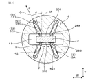
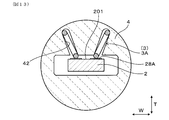
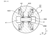
- 3 is a cross-sectional view taken along the line III-III in FIG. 1 and showing the periphery of a spring terminal in the gas sensor according to Embodiment 1.
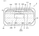
- FIG. 2 is a cross-sectional view showing a sensor element according to Embodiment 1.
- FIG. 2 is an exploded perspective view showing a sensor element according to the first embodiment.
- FIG. 8 is a cross-sectional view taken along line VIII-VIII in FIG. 1, showing the periphery of the spring insulator according to the first embodiment.
- Sectional drawing equivalent to the III-III arrow of FIG. 1 which shows the insulator for spring in which the spring terminal was hold
- FIG. 1 Sectional drawing which shows the state which inserts a sensor element into the insertion hole of the insulator for springs by which the spring terminal was hold
- FIG. Sectional drawing equivalent to the III-III arrow of FIG. 1 which shows the insulator for spring in which the spring terminal was hold
- Sectional drawing equivalent to the III-III arrow of FIG. 1 which shows the state by which the sensor element was inserted in the insertion hole of the insulator for spring by which the spring terminal was hold
- Sectional drawing equivalent to the III-III arrow of FIG. 1 which shows the periphery of the spring terminal in the other gas sensor concerning Embodiment 1.
- Sectional drawing equivalent to the III-III arrow of FIG. 1 which shows the periphery of the spring terminal in a gas sensor concerning Embodiment 2.
- FIG. Explanatory drawing which shows the periphery of the terminal contact part in the outer surface of a sensor element concerning Embodiment 2 in the state seen from the thickness direction of a sensor element.
- Sectional drawing of the III-III arrow equivalent of FIG. 1 which shows the periphery of the spring terminal in the other gas sensor concerning Embodiment 2.
- FIG. Sectional drawing which shows the formation state of the holding groove of the insulator for springs concerning Embodiment 3, in the state seen from the thickness direction of the sensor element.
- FIG. 1 which shows the formation state of the holding groove of the insulator for springs concerning Embodiment 3.
- FIG. Sectional drawing equivalent to the III-III arrow of FIG. 1 which shows the formation state of the holding groove of the insulator for other springs concerning Embodiment 3.
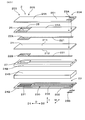
- FIG. Explanatory drawing which shows the spring terminal which contacts the terminal contact part of a sensor element concerning Embodiment 4.
- the gas sensor 1 of the present embodiment includes a sensor element 2, a plurality of spring terminals 3, and a spring insulator 4.
- the sensor element 2 is for performing gas detection, and a plurality of terminal contact portions 28A and 28B are provided on the outer surfaces 201 and 202 of the proximal end portion 204 of the sensor element 2.
- the plurality of spring terminals 3 are configured by a bending wire.
- the spring insulator 4 has an insertion hole 41 into which the proximal end 204 of the sensor element 2 is inserted, and a plurality of holding grooves 42 communicated with the insertion hole 41.
- the spring terminal 3 is extended from the holding portion 31 held in the holding groove 42 and the holding portion 31 and is bent with respect to the holding portion 31 to contact the terminal contact portions 28A and 28B. And an arm portion 32.
- an arm portion for the holding portion 31 in the inclined spring terminal 3A which is at least one of the plurality of spring terminals 3
- the deflection direction F of 32 is inclined to the outer surface of the terminal contact portions 28A and 28B.
- All the spring terminals 3 in this embodiment are inclined spring terminals 3A. Further, the outer surfaces of the terminal contact portions 28A and 28B refer to surfaces parallel to the outer surfaces 201 and 202 of the sensor element 2.
- the gas sensor 1 of the present embodiment is disposed in the pipe 8 of the exhaust system of an internal combustion engine (engine) of a vehicle, and detects oxygen or specific gas components in the exhaust gas G flowing in the pipe 8 It is.
- the gas sensor 1 can be disposed upstream of the location where the catalyst is disposed in the pipe 8 and can also be disposed downstream of the location where the catalyst is disposed in the pipe 8.
- the pipe 8 in which the gas sensor 1 is disposed can also be a pipe on the suction side of a turbocharger that uses the exhaust gas G to increase the pressure of the air drawn by the internal combustion engine.
- the pipe 8 for disposing the gas sensor 1 can also be a pipe in an exhaust gas recirculation mechanism that recirculates a portion of the exhaust gas G exhausted from the internal combustion engine to the exhaust gas passage to the intake gas passage of the internal combustion engine.
- the vehicle equipped with the pipe 8 for disposing the gas sensor 1 may be a general vehicle that travels using fuel, a vehicle that performs idling stop when the vehicle is stopped, a hybrid vehicle, or the like.
- the gas sensor 1 is an oxygen concentration cell type that detects an electromotive force generated between a pair of electrodes, and a limiting current type that uses limiting current characteristics generated when a voltage is applied between a pair of electrodes. Can.
- the gas sensor 1 of the present embodiment is used for detecting an air-fuel ratio of an internal combustion engine obtained from an exhaust gas G as an application for detecting gas.
- the gas sensor 1 also has an application for detecting a specific gas component such as NOx, an application for detecting an oxygen concentration of exhaust gas G exhausted from an internal combustion engine, an air fuel ratio of the internal combustion engine determined from the exhaust gas G It can be used for applications such as detecting whether the fuel rich side or the fuel lean side with respect to the fuel ratio.
- the sensor element 2 has a plate-like solid electrolyte body 21 provided with a pair of electrodes 22A and 22B, and a heater 23 stacked on the solid electrolyte body 21.
- a detection electrode 22A exposed to the exhaust gas G is provided on the first main surface 211 of the solid electrolyte body 21, and a reference electrode 22B exposed to the atmosphere A is provided on the second main surface 212 of the solid electrolyte body 21. It is done.
- a gas chamber 26 into which the exhaust gas G is introduced is formed adjacent to the first main surface 211 of the solid electrolyte body 21 by the insulating layer 24A stacked on the first main surface 211.
- the detection electrode 22A is disposed in the gas chamber 26.
- An air duct 27 into which the air A is introduced is formed adjacent to the second major surface 212 of the solid electrolyte body 21 by the insulating layer 24B of the heater 23 stacked on the second major surface 212.
- the reference electrode 22B is disposed in the air duct 27.
- a part of the insulating layer 24A forming the gas chamber 26 is formed as a porous diffusion resistance layer 25 having a property of allowing the exhaust gas G to pass therethrough.
- the diffusion resistance layer 25 is for introducing the exhaust gas G into the gas chamber 26 at a constant diffusion rate.
- the gas sensor 1 of the present embodiment constitutes an air-fuel ratio sensor, and a voltage for expressing a limiting current characteristic is applied between the detection electrode 22A and the reference electrode 22B.
- the gas chamber 26 is formed at the distal end portion 203 of the sensor element 2, and the air duct 27 is formed from the distal end portion 203 of the sensor element 2 to the end surface of the proximal end portion 204.
- the atmosphere A entering the gas sensor 1 is introduced into the atmosphere duct 27.
- the heater 23 has a heating element 230 embedded in the insulating layer 24B.
- the heat generating body 230 has a heat generating portion 231 which generates heat by energization and a pair of lead portions 232 connected to the heat generating portion 231.
- the heat generating portion 231 is disposed at a position facing the detection electrode 22A and the reference electrode 22B, and the pair of lead portions 232 is arranged from the heat generating portion 231 to the proximal end portion 204 of the sensor element 2.
- the lead portion 221 connected to the detection electrode 22A and the lead portion 221 connected to the reference electrode 22B are disposed up to the base end portion 204 of the sensor element 2.
- the sensor element 2 is formed in a long shape.
- the insertion direction D of the sensor element 2 is a direction along the longitudinal direction of the sensor element 2.
- a detection portion 205 including a detection electrode 22A, a reference electrode 22B, a gas chamber 26, and a diffusion resistance layer 25 is formed at the tip portion 203 in the longitudinal direction of the sensor element 2.
- a plurality of terminal contact portions 28A and 28B are formed on the outer surfaces 201 and 202 of the proximal end portion 204 in the longitudinal direction of the sensor element 2.
- a porous protective layer 29 is provided on the outer periphery of the distal end portion 203 of the sensor element 2 so as to cover the detection unit 205.
- the direction in which the terminal contact portions 28A and 28B are disposed to face the spring terminals 3 is referred to as a thickness direction T, and a direction orthogonal to the insertion direction D and the thickness direction T is referred to as a width direction W.
- the thickness direction T is a direction in which the detection electrode 22A and the reference electrode 22B are provided opposite to the solid electrolyte body 21.
- the insertion direction D, the thickness direction T, and the width direction W indicate directions common to the sensor element 2, the spring insulator 4, the gas sensor 1, and the like.
- the insertion direction D indicates a direction toward both sides, and in FIGS. 1, 2, 5, 6, etc., the distal end side in the insertion direction D is indicated by D1, and the proximal end side in the insertion direction D is D2. Indicated.
- a plurality of terminal contact portions 28A, 28B at the proximal end portion 204 of the sensor element 2 are provided side by side in the width direction W orthogonal to the insertion direction D.
- the terminal contact portions 28A and 28B are provided on the outer surfaces 201 and 202 on both sides of the sensor element 2 in the thickness direction T.
- the plurality of terminal contact portions 28A and 28B are connected to two first terminal contact portions 28A respectively connected to the lead portion 221 of the detection electrode 22A and the lead portion 221 of the reference electrode 22B, and 2 connected to the lead portion 232 of the heating element 230. And two second terminal contact portions 28B.
- first terminal contact portions 28A are arranged side by side in the width direction W on the first outer surface 201 of the sensor element 2, and two second terminals on the second outer surface 202 of the sensor element 2.
- the contact portions 28B are arranged side by side in the width direction W.
- the first outer surface 201 is an outer surface located on the side where the solid electrolyte body 21 is provided with the detection electrode 22A
- the second outer surface 202 is an outer surface located on the side where the solid electrolyte body 21 is provided with a reference electrode 22B. is there.
- the insulating layer 24A is formed over the entire length in the longitudinal direction of the solid electrolyte body 21, and the first outer surface 201 and the second outer surface 202 of the sensor element 2 are of the insulating layers 24A and 24B. It is an outer surface.
- first outer surface 201 is the outer surface of solid electrolyte body 21. It may be
- Each of the electrodes 22A and 22B is made of a material containing a noble metal having catalytic activity to oxygen, and the solid electrolyte body 21 is made of a zirconia material having conductivity of oxygen ions.
- the insulating layers 24A and 24B and the diffusion resistance layer 25 are made of an alumina material as an insulating ceramic.
- an element insulator 5 for inserting and holding the sensor element 2 and a spring insulator 4 for holding a plurality of spring terminals 3 are disposed.
- the element insulator 5 is also referred to as an insulator, and is formed of an insulating ceramic such as alumina.
- the element insulator 5 is formed by compressing ceramic powder.
- an arrangement hole 51 penetrating in the insertion direction D is formed in order to arrange the sensor element 2.
- An intermediate position in the longitudinal direction of the sensor element 2 is inserted into the arrangement hole 51.
- the sensor element 2 is fixed to the element insulator 5 by a glass material 53 or the like filled in a recess 52 formed on the base end side of the arrangement hole 51.
- a housing hole 61 penetrating in the insertion direction D is formed in the housing 6.
- the element insulator 5 is disposed in the housing hole 61.
- a screw portion 62 and a hexagonal flange portion 63 for attaching the gas sensor 1 inserted into the attachment hole 81 provided in the pipe 8 to the pipe 8 are formed all around the outer periphery of the housing 6 There is.
- a wiring cover 7 ⁇ / b> A covering the spring insulator 4 is attached to the proximal end portion of the housing 6.
- the wiring cover 7A is configured of an inner circumferential cover 71 located on the inner circumferential side and an outer circumferential cover 72 overlapping the outer circumferential side of the inner circumferential cover 71.
- the outer peripheral cover 72 is formed with an introduction hole 721 into which the atmosphere A is introduced.
- a filter 73 formed of a porous sheet is disposed between the inner cover 71 and the outer cover 72 so as to cover the introduction hole 721.
- the filter 73 has a property of passing a gas but not a liquid.
- a rubber bush 74 for inserting and holding the lead wire 34 and closing the inside of the wiring cover 7A is disposed on the inner peripheral side of the outer peripheral cover 72.
- the air A introduced into the wiring cover 7A via the introduction hole 721 and the filter 73 is introduced into the air duct 27 from the end face of the sensor element 2 on the proximal end side.
- An element cover 7 ⁇ / b> B that covers the tip end portion of the sensor element 2 is attached to the tip end portion of the housing 6.
- the exhaust gas G passing through the piping 8 of the exhaust system is introduced to the detection part 205 of the sensor element 2 and is circulated for circulating the inside and the outside of the element cover 7B. Holes 75 are formed.
- the spring insulator 4 is also referred to as an insulator, and is formed of an insulating ceramic such as alumina.
- the spring insulator 4 is formed by compressing ceramic powder.
- the spring insulator 4 is disposed so as to overlap the proximal end side of the element insulator 5 in the insertion direction D, and accommodates the proximal end portion 204 of the sensor element 2.
- the insertion hole 41 of the spring insulator 4 is a bottomed hole which does not penetrate the spring insulator 4 from the end face on the tip side where the sensor element 2 is inserted. It is formed as.
- the insertion hole 41 is formed at a central position in a plane orthogonal to the insertion direction D.
- the insertion hole 41 is formed as a hole of a substantially square cross section in accordance with the shape of the sensor element 2 having a substantially square cross section.
- a plurality of through holes 43 into which the end portions of the holding portions 31 of the plurality of spring terminals 3 are inserted are formed in the base end portion of the spring insulator 4 There is.
- the holding groove 42 of the spring insulator 4 is formed from the end face of the tip end side of the spring insulator 4 and is communicated with the insertion hole 41 in the thickness direction T.
- the holding groove 42 is formed to be inclined with respect to the thickness direction T in order to arrange the inclined spring terminal 3A in a state in which the inclined spring terminal 3A is inclined with respect to the thickness direction T.
- a part of the holding part 31 and a part of the arm part 32 are arranged.
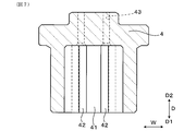
- the outer peripheral surface as a side surface parallel to the insertion direction D of the insulator 4 for spring has a circular cross-sectional shape. As shown in FIG. 7, the holding groove 42 is continuously formed from the end surface on the tip end side of the spring insulator 4 to the base end side.
- the spring insulator 4 is provided with four inclined spring terminals 3A that individually contact the two first terminal contact portions 28A and the two second terminal contact portions 28B. Is held.
- the arm portion 32 of the inclined spring terminal 3A is folded back from the holding portion 31 and is opposed to the holding portion 31 in the bending direction F.
- the arm portion 32 is formed to face the holding portion 31 so that the spring characteristic of the arm portion 32 can be developed so that the arm portion 32 can bend (elastically deform) with respect to the holding portion 31. It will be easier.
- the bending direction F of the arm portion 32 in the present embodiment is a direction in which the holding portion 31 and the arm portion 32 face each other.
- the holding portion 31 includes a main body portion 311 disposed at an outer peripheral end of the holding groove 42, an extending portion 312 inserted into the through hole 43, a main body portion 311 and an extending portion And a connection portion 313 connecting the connection portion 312.
- the main body portion 311 and the extension portion 312 are formed to be offset in a direction perpendicular to the insertion direction D in parallel with each other.
- the arm portion 32 includes a curved portion 321 connected to the main portion 311 of the holding portion 31, a straight portion 322 connected to the curved portion 321, and a contact portion 323 provided on the straight portion 322 and contacting the terminal contact portions 28A and 28B. Have.
- the contact portion 323 is formed in a curved shape.
- the arm portion 32 is bent so that the linear portion 322 and the contact portion 323 approach the main body portion 311 of the holding portion 31 by mainly elastically deforming the curved portion 321 so as to reduce the radius of curvature.
- the arm portion 32 is also bent when the entire arm portion 32 except the curved portion 321 is warped.
- the terminal fitting 33 from the base end side of the spring insulator 4 Is attached.
- a lead 34 connected to a control device or the like outside the gas sensor 1 is attached to the terminal fitting 33.
- the spring terminal 3 of the present embodiment is formed of a round wire (steel wire) having a circular cross section and a wire diameter in the range of ⁇ 0.4 to 0.7 mm.
- the holding portion 31 and the arm portion 32 are formed by bending a round wire.
- a round wire it is possible to secure the strength and to minimize the width of the wire forming the spring terminal 3 as much as possible.
- the space occupied by the plurality of spring terminals 3 in the spring insulator 4 can be reduced, and the miniaturization of the spring insulator 4 and, in addition, the gas sensor 1 can be achieved. .
- the gap S between the spring terminal 3 and the holding groove 42 of the spring insulator 4 in which the spring terminal 3 is disposed is The amount of displacement of the spring terminal 3 in the width direction W in the holding groove 42 increases. Therefore, the width in the width direction W of the terminal contact portions 28A and 28B in the sensor element 2 needs to be increased, which causes the miniaturization of the sensor element 2 to be hindered.
- the width of the holding groove 42 of the spring insulator 4 in which the spring terminal 3 is disposed is preferably 0.7 mm or more from the viewpoint of securing the strength of the mold for molding the spring insulator 4.
- the cross-sectional shape of the spring terminal 3 may be a flat shape, an elliptical shape, an angular shape including a quadrilateral shape, or the like.
- the aspect ratio which is the ratio of the length of the long diameter portion (long side portion) to the length of the short diameter portion (short side portion) in the cross section of the spring terminal 3 is in the range of 1: 1 to 1: 2. You can do so.
- the inclined spring terminals 3 ⁇ / b> A are arranged side by side in the width direction W, and are arranged at positions facing each other via the sensor element 2. Further, the inclined spring terminals 3A are arranged in a pair in the width direction W on both sides in the thickness direction T of the sensor element 2. Two inclined spring terminals 3A are provided in the width direction W opposite to the first outer surface 201, corresponding to the two first terminal contact portions 28A provided on the first outer surface 201 of the proximal end portion 204 of the sensor element 2. They are arranged side by side.
- the inclined spring terminals 3A are opposed to the second outer surface 202 in the width direction W corresponding to the two second terminal contact portions 28B provided on the second outer surface 202 of the proximal end portion 204 of the sensor element 2. Two are arranged side by side. The two inclined spring terminals 3A disposed opposite to the first outer surface 201 and the two inclined spring terminals 3A disposed opposite to the second outer surface 202 face each other via the sensor element 2.
- each of the inclined spring terminals 3A inclines is such that the arm portion 32 is positioned closer to the center in the width direction W of the sensor element 2 than the holding portion 31.
- the four inclined spring terminals 3A are arranged to be inclined with respect to the thickness direction T of the sensor element 2 in a state close to the X shape.
- the inclined spring terminals 3A face each other through the sensor element 2 in the thickness direction T
- the contact portions 323 of the arm portions 32 of the inclined spring terminals 3A facing each other come into contact with each other.
- the arm portions 32 are positioned on the center side in the width direction W of the sensor element 2 with respect to the holding portion 31 so that the contact portions 323 of the arm portions 32 of the inclined spring terminals 3A opposed to each other are In any case, the position shifts to the center side in the width direction W. Therefore, the arm portions 32 of the inclined spring terminals 3A are prevented from being displaced to different sides in the width direction W.
- the contact portion 323 of the arm portion 32 is prevented from being displaced outward in the width direction W from the terminal contact portions 28A and 28B, and is prevented from coming out in the width direction W of the sensor element 2.
- the direction in which each contact portion 323 of the arm portion 32 is displaced is indicated by an arrow P.
- each inclined spring terminal 3A since the arm portion 32 of each inclined spring terminal 3A is located on the center side of the holding portion 31 in the width direction W of the sensor element 2, in the spring insulator 4, the plurality of inclined spring terminals 3A are as radial as possible. It can be placed close to Thus, the distance between the holding portions 31 of the pair of inclined spring terminals 3A aligned in the width direction W can be increased. Therefore, interference between the terminal fittings 33 connected to the inclined spring terminals 3A and the lead wires 34 connected to the inclined spring terminals 3A through the terminal fittings 33 can be easily avoided.
- the arm portions 32 of the respective inclined spring terminals 3A in the state of being in contact with the terminal contact portions 28A, 28B of the sensor element 2 are terminals compared to the state before contacting the terminal contact portions 28A, 28B. It is bent in a state in which the inclination angle ⁇ of the central axis O along the bending direction F with respect to a perpendicular M perpendicular to the outer surface of the contact portions 28A and 28B is increased.
- the central axis O refers to an imaginary line passing through the center of the cross section of the arm portion 32 when viewed in the insertion direction D.
- the arm portion 32 of the inclined spring terminal 3A contacts the side surface 421 on the center side in the width direction W of the holding groove 42, and the position relative to the outer surface of the terminal contact portions 28A and 28B is fixed. .
- the width of the holding groove 42 of the spring insulator 4 is larger than the wire diameter of the spring terminal 3.
- a gap S is formed between the holding groove 42 and the spring terminal 3.
- the inclination angle ⁇ between a perpendicular M and the outer surface of 28 B is in the range of 5 to 45 °. If the inclination angle ⁇ is less than 5 °, it is difficult to obtain the effect of the bending direction F of the arm portion 32 of the inclined spring terminal 3A being inclined with respect to the outer surfaces of the terminal contact portions 28A and 28B.
- the two inclined spring terminals 3A aligned in the width direction W are two inclinations aligned in the width direction W
- the arm portions 32 of the spring terminals 3A are disposed so as not to be in contact with each other at a position and an inclination angle.
- the insertability of the sensor element 2 into the insertion hole 41 is deteriorated.
- the contact state of the spring terminal 3 with the terminal contact portions 28A and 28B on the outer surfaces 201 and 202 of the sensor element 2 is kept good It is devising. Specifically, a spring restoring force to be applied to the arm portion 32 of the spring terminal 3 is applied to the outer surfaces of the terminal contact portions 28A and 28B in a state of being inclined in the thickness direction T. And the contact part 323 of the arm part 32 forms the state which can be displaced only on the center side of the width direction W of the outer surface of terminal contact part 28A, 28B.
- the arm portions 32 of the spring terminals 3X contact each other in the thickness direction T as a comparative embodiment, the spring terminals 3X are in contact with the spring restoring force along the thickness direction T.
- the arm portions 32 may be misaligned to different sides in the width direction W and may pass each other in the width direction W because they are formed of round wire rods.
- the spring insulator is indicated by reference numeral 4X
- the holding groove is indicated by reference numeral 42X.
- each inclined spring terminal 3A contacts the side surface 421 on the center side in the width direction W of the holding groove 42 of the spring insulator 4.
- the direction and amount of displacement of the contact portion 323 of the arm portion 32 is regulated, and the position where the contact portion 323 of the arm portion 32 contacts the outer surfaces of the terminal contact portions 28A and 28B is determined. Therefore, the contact position of the arm portion 32 with respect to the terminal contact portions 28A and 28B is fixed, and a contact failure can be less likely to occur between the arm portion 32 and the terminal contact portions 28A and 28B.
- the state of the inclined spring terminal 3A can be maintained properly. So, according to the gas sensor 1 of this form, the state of the electrical connection between the spring terminal 3 and the sensor element 2 can be made favorable.
- the inclination spring terminal 3A which contacts the 2nd terminal contact part 28B and the 2nd terminal contact part 28B becomes unnecessary.
- the first terminal contact portion 28A is formed on the first outer surface 201 of the sensor element 2
- the inclined spring terminal 3A is the first terminal contact of the first outer surface 201 of the sensor element 2. Only two contacting portions 28A can be used.
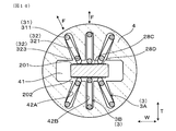
- Second Embodiment shows the case where the number of holding the spring terminals 3 in the spring insulator 4 is six. As shown in FIG. 14, in addition to the four inclined spring terminals 3A, the two vertical spring terminals 3B are held by the spring insulator 4 of the present embodiment.
- the vertical spring terminals 3 ⁇ / b> B are the spring terminals 3 other than the inclined spring terminals 3 ⁇ / b> A among the plurality of spring terminals 3 held by the spring insulator 4.
- the vertical spring terminals 3B are disposed between the pair of inclined spring terminals 3A aligned in the width direction W such that the bending direction F of the arm portion 32 is perpendicular to the outer surfaces of the terminal contact portions 28A and 28B.
- a holding groove 42 A for the inclined spring terminal 3 A inclined in the thickness direction T and a holding groove 42 B for the vertical spring terminal 3 B parallel to the thickness direction T are formed.
- the number of the electrodes provided in the sensor element 2 is four, and the number of the lead portions 232 of the heating element 230 of the heater 23 is two, so that a total of six spring terminals 3 are used.
- the gas sensor 1 of the present embodiment can be, for example, a NOx sensor that detects the concentration of a specific gas component such as NOx (nitrogen oxide).
- a pump electrode provided on the first major surface 211 of the solid electrolyte body 21 for discharging oxygen in the exhaust gas G in the gas chamber 26 and residual oxygen of the exhaust gas G in the gas chamber 26
- a monitor electrode provided on the first main surface 211 of the solid electrolyte body 21 to detect the concentration, and a first main surface 211 of the solid electrolyte body 21 to detect the NOx concentration of the exhaust gas G in the gas chamber 26
- Four electrodes of the sensor electrode and the reference electrode exposed to the atmosphere A provided on the second major surface 212 of the solid electrolyte body 21 are used.
- a heater 23 is stacked on the sensor element 2.
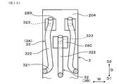
- three terminal contact portions 28C and 28D are formed on the first outer surface 201 and the second outer surface 202 of the sensor element 2, respectively.
- the first outer surface 201 is formed with three terminal contact portions 28C and 28D connected to the lead portions 221 of the pump electrode, the monitor electrode and the sensor electrode.
- On the second outer surface 202 three terminal contact portions 28C and 28D connected to the lead portion 221 of the reference electrode and the lead portion 232 of the heating element 230 of the heater 23 are formed.
- the three terminal contact portions 28C and 28D formed on the outer surfaces 201 and 202 of the sensor element 2 two proximal ends formed in the width direction W on the base end side of the proximal end portion 204 of the sensor element 2
- the arm portions 32 of the two inclined spring terminals 3A aligned in the width direction W are in contact with the two proximal terminal contact portions 28D.
- the arm portion 32 of the vertical spring terminal 3B is in contact with the tip side terminal contact portion 28C.
- the formation width in the width direction W of the distal side terminal contact portion 28C in contact with the vertical spring terminal 3B is larger than the formation width in the width direction W of the proximal terminal contact portion 28D.
- positional deviation of the arm portion 32 of the vertical spring terminal 3 ⁇ / b> B to any side in the width direction W of the sensor element 2 can be tolerated.
- the correspondence relationship between the pump electrode, the monitor electrode, the sensor electrode, the reference electrode, the heating element 230, and the inclined spring terminal 3A and the vertical spring terminal 3B can be any correspondence relationship.
- the vertical spring terminals 3B are disposed between the pair of inclined spring terminals 3A according to the increase in the number of electrodes used for the sensor element 2.
- formation width of tip end side terminal contact part 28C which vertical spring terminal 3B contacts width direction W is larger than formation width of width end W of proximal end terminal contact part 28D which inclination spring terminal 3A contacts.
- the heater 23 When the heater 23 is not stacked on the sensor element 2 of the NOx sensor, four electrodes of the pump electrode, the monitor electrode, the sensor electrode, and the reference electrode are provided on the first outer surface 201 and the second outer surface 202 of the sensor element 2. It can be made to respond
- Embodiment 3 shows a modification of the holding groove 42 in the spring insulator 4.
- the holding groove 42 is not formed continuously from the end face of the tip end side of the spring insulator 4 to the base end side as shown in FIG. 17, but from the recess 44 formed in the tip side portion of the spring insulator 4 It may be formed toward the proximal side.
- the holding groove 42 can be formed in a step-like shape in the state seen from the insertion direction D as shown in FIGS. 18 and 19 in addition to being formed linearly in the state seen from the insertion direction D .
- the step-like holding groove 42 is formed such that the inclined spring terminal 3A is disposed to be inclined with respect to the thickness direction T of the sensor element 2.
- the holding portion 31 of the inclined spring terminal 3A is disposed at an outer corner of the stepped holding groove 42 in the width direction W.
- the arm portion 32 of the inclined spring terminal 3A is arranged from the holding portion 31 toward the center side in the width direction W.
- the width in the width direction W of the portion 422 located on the center side in the thickness direction T in the holding groove 42 is the width in the width direction W of the portion 423 located outside the thickness direction T in the holding groove 42. An example smaller than this is shown.
- the portion 422 located on the center side in the thickness direction T in the holding groove 42 is formed on the center side in the width direction W than the portion 423 located on the outer side in the thickness direction T in the holding groove 42.
- the inclined spring terminals 3A can be inclined with respect to the outer surfaces of the terminal contact portions 28A and 28B.
- the present embodiment shows a modification of the shape of the spring terminal 3.
- the holding portion 31 of the spring terminal 3 can be formed in a straight line parallel to the insertion direction D as shown in FIG. 20, besides being bent and formed so that the position in the bending direction F is offset.
- the arm portion 32 extends from the end portion on the tip end side of the holding portion 31 in the insertion direction D to the tip end side, as shown in FIG. It can also be formed in the Moreover, although it is against the miniaturization, as shown in FIG. 22, the arm 32 is folded back from the end on the distal end side of the holding portion 31 in the insertion direction D to the proximal end and is further folded back to the distal end. It can also be formed into
- FIG. 20 to 22 show the spring terminal 3 disposed on the outer surface on one side of the sensor element 2.
- FIG. The spring terminals 3 may be disposed on the outer surfaces on both sides of the sensor element 2.
- the other configuration, effects, and the like of the gas sensor 1 of the present embodiment are the same as those of the first embodiment.
- the constituent elements indicated by the same reference numerals as the reference numerals in the first embodiment are the same as those in the first embodiment.
- the number of spring terminals 3 used in the gas sensor 1 can be appropriately changed in accordance with the number of electrodes provided in the sensor element 2.
- two solid electrolyte bodies 21 may be used in the gas sensor 1, and the solid electrolyte body 21 in which the pump electrode is formed and the solid electrolyte body 21 in which the monitor electrode and the sensor electrode are formed may be different.
- the structure shown in each embodiment can also be applied to the sensor element 2 in which the air duct 27 is not formed.
Abstract
ガスセンサは、センサ素子(2)、複数のバネ端子(3)及びバネ用インシュレータ(4)を備える。複数のバネ端子(3)は、屈曲する線材によって構成されている。バネ用インシュレータ(4)は、センサ素子(2)の基端部が挿入された挿入穴(41)と、挿入穴(41)に連通された複数の保持溝(42)とを有する。バネ端子(3)は、保持溝(42)内に保持される保持部(31)と、保持部(31)から延設され、保持部(31)に対して撓んでセンサ素子(2)の端子接触部(28A,28B)に接触するアーム部(32)とを有する。挿入穴(41)へのセンサ素子(2)の挿入方向から見たときに、バネ端子(3)における、保持部(31)に対するアーム部(32)の撓み方向(F)は、端子接触部(28A,28B)の外面に対して傾斜している。
Description
本出願は、2017年8月31日に出願された日本の特許出願番号2017-167558号に基づくものであり、その記載内容を援用する。
本開示は、インシュレータに保持されたバネ端子にセンサ素子が接触する構造を有するガスセンサに関する。
ガスセンサは、内燃機関から排気される排ガス中の酸素、特定ガス成分等の濃度を検出するために用いられる。ガスセンサのセンサ素子には、板状の固体電解質体に対して、排ガスが導入されるガス室等を形成する絶縁層が積層された積層タイプのものがある。積層タイプのセンサ素子の端部は、インシュレータの挿入穴に収容され、インシュレータの保持溝に保持されたバネ端子に電気的に接続される。
より具体的には、バネ端子は、保持部と、保持部に対して撓んでセンサ素子に接触するアーム部とを有する。バネ端子は、センサ素子の両側に配置され、アーム部がセンサ素子に接触して撓む際に、センサ素子を両側から挟み込む。また、センサ素子の外面には、固体電解質体に設けられた電極に繋がる端子接触部が配置されている。そして、バネ端子のアーム部が端子接触部に接触し、センサ素子の電極がバネ端子を介して、ガスセンサの外部に電気接続される。
また、車両等への搭載上の制約から、ガスセンサを小型化する要求がある。そこで、バネ端子を線材によって構成し、バネ端子の配置間隔を小さくするとともに、インシュレータの外形を小さくすることが行われている。例えば、特許文献1においては、線材によって構成されたバネ端子を用いたガスセンサについて開示されている。
ガスセンサの組付時においては、複数の保持溝のそれぞれにバネ端子が保持されたインシュレータの挿入穴に対して、センサ素子の端部が挿入される。しかしながら、特許文献1等に開示されるバネ端子のアーム部は、センサ素子の外面における端子接触部に対して垂直に接触して、保持部に対して撓む。このアーム部の撓み方向は、センサ素子の厚み方向として、端子接触部の外面に対して垂直な方向となる。
そのため、アーム部が撓む際に、アーム部が端子接触部の外面上を滑るときには、アーム部が電極接触部に対して左右のいずれかに位置ずれするおそれがある。その結果、端子接触部に対するアーム部の接触位置が定まらず、アーム部と端子接触部との間に接触不良が生じるおそれがある。ゆえに、バネ端子とセンサ素子との間の電気接続の状態を改善するためには、更なる工夫が必要とされる。
本開示は、バネ端子とセンサ素子との間の電気接続の状態を良好にすることができるガスセンサを提供しようとして得られたものである。
本開示の一態様は、端子接触部が基端部の外面に複数設けられ、ガス検出を行うためのセンサ素子と、
屈曲する線材によって構成された複数のバネ端子と、
前記センサ素子の前記基端部が挿入された挿入穴、及び前記挿入穴に連通された複数の保持溝を有するインシュレータと、を備えるガスセンサにおいて、
前記バネ端子は、前記保持溝内に保持される保持部と、前記保持部から延設され、前記保持部に対して撓んで前記端子接触部に接触するアーム部とを有しており、
前記挿入穴への前記センサ素子の挿入方向から見たときに、複数の前記バネ端子のうちの少なくとも1つである傾斜バネ端子における、前記保持部に対する前記アーム部の撓み方向は、前記端子接触部の外面に対して傾斜している、ガスセンサにある。
屈曲する線材によって構成された複数のバネ端子と、
前記センサ素子の前記基端部が挿入された挿入穴、及び前記挿入穴に連通された複数の保持溝を有するインシュレータと、を備えるガスセンサにおいて、
前記バネ端子は、前記保持溝内に保持される保持部と、前記保持部から延設され、前記保持部に対して撓んで前記端子接触部に接触するアーム部とを有しており、
前記挿入穴への前記センサ素子の挿入方向から見たときに、複数の前記バネ端子のうちの少なくとも1つである傾斜バネ端子における、前記保持部に対する前記アーム部の撓み方向は、前記端子接触部の外面に対して傾斜している、ガスセンサにある。
前記一態様のガスセンサにおいては、インシュレータに保持されたバネ端子のアーム部の撓み方向に工夫をしている。具体的には、挿入穴へのセンサ素子の挿入方向から見たときに、複数のバネ端子のうちの少なくとも1つにおける、保持部に対するアーム部の撓み方向は、端子接触部の外面に対して傾斜している。
そして、インシュレータの挿入穴へセンサ素子を挿入する際には、アーム部は、端子接触部の外面に対して傾斜する方向に撓む。また、アーム部が端子接触部の外面上を滑る際には、アーム部が滑る方向が規制される。具体的には、アーム部は、端子接触部の外面の垂線に対する傾斜角度が大きくなる方向に滑る。
これにより、端子接触部に対するアーム部の接触位置が定まり、アーム部と端子接触部との間に接触不良が生じにくくすることができる。それ故、前記一態様のガスセンサによれば、バネ端子とセンサ素子との間の電気接続の状態を良好にすることができる。
なお、本開示の一態様において示す各構成要素のカッコ書きの符号は、実施形態における図中の符号との対応関係を示すが、各構成要素を実施形態の内容のみに限定するものではない。
本開示についての目的、特徴、利点等は、添付の図面を参照する後記の詳細な記述によって、より明確になる。本開示の図面を以下に示す。
実施形態1にかかる、ガスセンサを示す断面図。
実施形態1にかかる、ガスセンサにおけるバネ端子の周辺を拡大して示す断面図。
実施形態1にかかる、ガスセンサにおけるバネ端子の周辺を示す、図1のIII-III矢視断面図。
実施形態1にかかる、センサ素子を示す断面図。
実施形態1にかかる、センサ素子を分解して示す斜視図。
実施形態1にかかる、センサ素子の外面における端子接触部の周辺を、センサ素子の厚み方向から見た状態で示す説明図。
実施形態1にかかる、バネ用インシュレータを、センサ素子の厚み方向から見た状態で示す断面図。
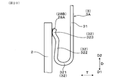
実施形態1にかかる、バネ用インシュレータの周辺を示す、図1のVIII-VIII矢視断面図。
実施形態1にかかる、センサ素子が挿入される前の状態の、バネ端子が保持されたバネ用インシュレータを示す、図1のIII-III矢視相当の断面図。
実施形態1にかかる、バネ端子が保持されたバネ用インシュレータの挿入穴へ、センサ素子を挿入する状態を示す断面図。
比較形態にかかる、センサ素子が挿入される前の状態の、バネ端子が保持されたバネ用インシュレータを示す、図1のIII-III矢視相当の断面図。
比較形態にかかる、バネ端子が保持されたバネ用インシュレータの挿入穴にセンサ素子が挿入された状態を示す、図1のIII-III矢視相当の断面図。
実施形態1にかかる、他のガスセンサにおけるバネ端子の周辺を示す、図1のIII-III矢視相当の断面図。
実施形態2にかかる、ガスセンサにおけるバネ端子の周辺を示す、図1のIII-III矢視相当の断面図。
実施形態2にかかる、センサ素子の外面における端子接触部の周辺を、センサ素子の厚み方向から見た状態で示す説明図。
実施形態2にかかる、他のガスセンサにおけるバネ端子の周辺を示す、図1のIII-III矢視相当の断面図。
実施形態3にかかる、バネ用インシュレータの保持溝の形成状態を、センサ素子の厚み方向から見た状態で示す断面図。
実施形態3にかかる、バネ用インシュレータの保持溝の形成状態を示す、図1のIII-III矢視相当の断面図。
実施形態3にかかる、他のバネ用インシュレータの保持溝の形成状態を示す、図1のIII-III矢視相当の断面図。
実施形態4にかかる、センサ素子の端子接触部に接触するバネ端子を示す説明図。
実施形態4にかかる、センサ素子の端子接触部に接触する他のバネ端子を示す説明図。
実施形態4にかかる、センサ素子の端子接触部に接触する他のバネ端子を示す説明図。
前述したガスセンサにかかる好ましい実施形態について、図面を参照して説明する。
<実施形態1>
本形態のガスセンサ1は、図1及び図2に示すように、センサ素子2、複数のバネ端子3及びバネ用インシュレータ4を備える。センサ素子2は、ガス検出を行うためのものであり、センサ素子2の基端部204の外面201,202には、複数の端子接触部28A,28Bが設けられている。複数のバネ端子3は、屈曲する線材によって構成されている。バネ用インシュレータ4は、センサ素子2の基端部204が挿入された挿入穴41と、挿入穴41に連通された複数の保持溝42とを有する。
<実施形態1>
本形態のガスセンサ1は、図1及び図2に示すように、センサ素子2、複数のバネ端子3及びバネ用インシュレータ4を備える。センサ素子2は、ガス検出を行うためのものであり、センサ素子2の基端部204の外面201,202には、複数の端子接触部28A,28Bが設けられている。複数のバネ端子3は、屈曲する線材によって構成されている。バネ用インシュレータ4は、センサ素子2の基端部204が挿入された挿入穴41と、挿入穴41に連通された複数の保持溝42とを有する。
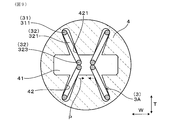
バネ端子3は、図2に示すように、保持溝42内に保持される保持部31と、保持部31から延設され、保持部31に対して撓んで端子接触部28A,28Bに接触するアーム部32とを有する。図3に示すように、挿入穴41へのセンサ素子2の挿入方向Dから見たときに、複数のバネ端子3のうちの少なくとも1つである傾斜バネ端子3Aにおける、保持部31に対するアーム部32の撓み方向Fは、端子接触部28A,28Bの外面に対して傾斜している。
本形態の全てのバネ端子3は、傾斜バネ端子3Aである。また、端子接触部28A,28Bの外面とは、センサ素子2の外面201,202と平行な表面のことをいう。
以下に、本形態のガスセンサ1について詳説する。
(内燃機関)
図1に示すように、本形態のガスセンサ1は、車両の内燃機関(エンジン)の排気系統の配管8に配置されて、配管8内を流れる排ガスG中の酸素又は特定ガス成分を検出するものである。ガスセンサ1は、配管8における、触媒の配置箇所よりも上流側に配置することができ、配管8における、触媒の配置箇所よりも下流側に配置することもできる。また、ガスセンサ1を配置する配管8は、排ガスGを利用して内燃機関が吸入する空気の圧力を高める過給機の吸入側の配管とすることもできる。また、ガスセンサ1を配置する配管8は、内燃機関から排気通路に排気される排ガスGの一部を、内燃機関の吸気通路に再循環させる排気再循環機構における配管とすることもできる。
また、ガスセンサ1を配置する配管8が搭載された車両は、燃料を用いて走行する一般的な車両の他、停車時にアイドリングストップを行う車両、ハイブリッド車両等とすることができる。また、ガスセンサ1は、一対の電極間に生じる起電力を検出する酸素濃淡電池式のもの、一対の電極間に電圧を印加したときに生じる限界電流特性を利用する限界電流式のものとすることができる。
本形態のガスセンサ1は、ガス検出を行う用途として、排ガスGから求められる内燃機関の空燃比を検出する用途に用いられる。ガスセンサ1は、これ以外にも、NOx等の特定ガス成分を検出する用途、内燃機関から排気される排ガスGの酸素濃度を検出する用途、排ガスGから求められる内燃機関の空燃比が、理論空燃比に対して燃料リッチ側にあるか燃料リーン側にあるかを検出する用途等に用いることができる。
(センサ素子2)
図4及び図5に示すように、センサ素子2は、一対の電極22A,22Bが設けられた板状の固体電解質体21と、固体電解質体21に積層されたヒータ23とを有する。固体電解質体21の第1主面211には、排ガスGに晒される検出電極22Aが設けられており、固体電解質体21の第2主面212には、大気Aに晒される基準電極22Bが設けられている。固体電解質体21の第1主面211には、第1主面211に積層された絶縁層24Aによって、排ガスGが導入されるガス室26が隣接して形成されている。検出電極22Aは、ガス室26内に配置されている。固体電解質体21の第2主面212には、第2主面212に積層されたヒータ23の絶縁層24Bによって、大気Aが導入される大気ダクト27が隣接して形成されている。基準電極22Bは、大気ダクト27内に配置されている。
図4及び図5に示すように、センサ素子2は、一対の電極22A,22Bが設けられた板状の固体電解質体21と、固体電解質体21に積層されたヒータ23とを有する。固体電解質体21の第1主面211には、排ガスGに晒される検出電極22Aが設けられており、固体電解質体21の第2主面212には、大気Aに晒される基準電極22Bが設けられている。固体電解質体21の第1主面211には、第1主面211に積層された絶縁層24Aによって、排ガスGが導入されるガス室26が隣接して形成されている。検出電極22Aは、ガス室26内に配置されている。固体電解質体21の第2主面212には、第2主面212に積層されたヒータ23の絶縁層24Bによって、大気Aが導入される大気ダクト27が隣接して形成されている。基準電極22Bは、大気ダクト27内に配置されている。
ガス室26を形成する絶縁層24Aの一部は、排ガスGを通過させる性質を有する多孔質の拡散抵抗層25として形成されている。拡散抵抗層25は、一定の拡散速度でガス室26へ排ガスGを導入するものである。本形態のガスセンサ1は、空燃比センサを構成し、検出電極22Aと基準電極22Bとの間には、限界電流特性を発現するための電圧が印加される。また、ガス室26は、センサ素子2の先端部203に形成されており、大気ダクト27は、センサ素子2の先端部203から基端部204の端面まで形成されている。大気ダクト27へは、ガスセンサ1内に入る大気Aが導入される。
図5に示すように、ヒータ23は、絶縁層24B内に埋設された発熱体230を有する。発熱体230は、通電によって発熱する発熱部231と、発熱部231に繋がる一対のリード部232とを有する。発熱部231は、検出電極22A及び基準電極22Bに対向する位置に配置されており、一対のリード部232は、発熱部231からセンサ素子2の基端部204まで配置されている。また、検出電極22Aに繋がるリード部221及び基準電極22Bに繋がるリード部221は、センサ素子2の基端部204まで配置されている。
センサ素子2は、長尺形状に形成されている。センサ素子2の挿入方向Dは、センサ素子2の長尺方向に沿った方向となる。センサ素子2の長尺方向の先端部203には、検出電極22A、基準電極22B、ガス室26及び拡散抵抗層25による検知部205が形成されている。センサ素子2の長尺方向の基端部204の外面201,202には、複数の端子接触部28A,28Bが形成されている。また、図1及び図4に示すように、センサ素子2の先端部203の外周には、検知部205を覆うように多孔質保護層29が設けられている。
センサ素子2において、端子接触部28A,28Bが配置されてバネ端子3と向き合う方向を厚み方向Tといい、挿入方向Dと厚み方向Tとに直交する方向を幅方向Wという。厚み方向Tは、固体電解質体21に検出電極22Aと基準電極22Bとが対向して設けられた方向となる。また、挿入方向D、厚み方向T及び幅方向Wは、センサ素子2、バネ用インシュレータ4、ガスセンサ1等において共通する方向を示す。また、挿入方向Dは、両側に向けた方向を示し、図1、図2、図5、図6等においては、挿入方向Dにおける先端側をD1で示し、挿入方向Dにおける基端側をD2で示す。
図3、図5及び図6に示すように、センサ素子2の基端部204における端子接触部28A,28Bは、挿入方向Dに直交する幅方向Wに複数並んで設けられている。また、端子接触部28A,28Bは、センサ素子2の厚み方向Tの両側の外面201,202に設けられている。複数の端子接触部28A,28Bは、検出電極22Aのリード部221と、基準電極22Bのリード部221とにそれぞれ繋がる2つの第1端子接触部28Aと、発熱体230のリード部232に繋がる2つの第2端子接触部28Bとからなる。本形態においては、センサ素子2の第1外面201において、2つの第1端子接触部28Aが幅方向Wに並んで配置されており、センサ素子2の第2外面202において、2つの第2端子接触部28Bが幅方向Wに並んで配置されている。第1外面201は、固体電解質体21に検出電極22Aが設けられた側に位置する外面であり、第2外面202は、固体電解質体21に基準電極22Bが設けられた側に位置する外面である。
また、本形態においては、絶縁層24Aが固体電解質体21の長尺方向の全長に亘って形成されており、センサ素子2の第1外面201及び第2外面202は、絶縁層24A,24Bの外面である。なお、絶縁層24Aが、センサ素子2の先端部203を含む部位に形成され、センサ素子2の基端部204まで形成されていない場合には、第1外面201は、固体電解質体21の外面としてもよい。
各電極22A,22Bは、酸素に対する触媒活性を有する貴金属を含有する材料からなり、固体電解質体21は、酸素イオンの伝導性を有するジルコニア材料からなる。絶縁層24A,24B及び拡散抵抗層25は、絶縁性のセラミックスとしてのアルミナ材料からなる。
(素子用インシュレータ5)
図1に示すように、ガスセンサ1には、センサ素子2を挿通させて保持するための素子用インシュレータ5と、複数のバネ端子3を保持するためのバネ用インシュレータ4とが配置されている。素子用インシュレータ5は、絶縁碍子ともいい、アルミナ等の絶縁性のセラミックスによって形成されている。素子用インシュレータ5は、セラミックスの粉体を圧縮して成形されている。素子用インシュレータ5には、センサ素子2を配置するために、挿入方向Dに向けて貫通する配置穴51が形成されている。配置穴51には、センサ素子2の長尺方向の中間位置が挿通されている。センサ素子2は、配置穴51の基端側に形成された凹部52内に充填されるガラス材53等によって素子用インシュレータ5に固定されている。
図1に示すように、ガスセンサ1には、センサ素子2を挿通させて保持するための素子用インシュレータ5と、複数のバネ端子3を保持するためのバネ用インシュレータ4とが配置されている。素子用インシュレータ5は、絶縁碍子ともいい、アルミナ等の絶縁性のセラミックスによって形成されている。素子用インシュレータ5は、セラミックスの粉体を圧縮して成形されている。素子用インシュレータ5には、センサ素子2を配置するために、挿入方向Dに向けて貫通する配置穴51が形成されている。配置穴51には、センサ素子2の長尺方向の中間位置が挿通されている。センサ素子2は、配置穴51の基端側に形成された凹部52内に充填されるガラス材53等によって素子用インシュレータ5に固定されている。
(ハウジング6)
図1に示すように、ハウジング6には、挿入方向Dに向けて貫通するハウジング穴61が形成されている。素子用インシュレータ5は、ハウジング穴61内に配置されている。また、ハウジング6の外周の全周には、配管8に設けられた取付穴81に挿通されたガスセンサ1を、配管8に取り付けるための、ねじ部62及び六角形状のフランジ部63が形成されている。
図1に示すように、ハウジング6には、挿入方向Dに向けて貫通するハウジング穴61が形成されている。素子用インシュレータ5は、ハウジング穴61内に配置されている。また、ハウジング6の外周の全周には、配管8に設けられた取付穴81に挿通されたガスセンサ1を、配管8に取り付けるための、ねじ部62及び六角形状のフランジ部63が形成されている。
(配線用カバー7A及び素子用カバー7B)
図1に示すように、ハウジング6の基端側部分には、バネ用インシュレータ4を覆う配線用カバー7Aが装着されている。配線用カバー7Aは、内周側に位置する内周側カバー71と、内周側カバー71の外周側に重なる外周側カバー72とによって構成されている。外周側カバー72には、大気Aが導入される導入孔721が形成されている。内周側カバー71と外周側カバー72との間には、多孔質のシートによって形成されたフィルタ73が、導入孔721を覆う状態で配置されている。フィルタ73は、気体を通過させる一方、液体を通過させない性質を有する。
図1に示すように、ハウジング6の基端側部分には、バネ用インシュレータ4を覆う配線用カバー7Aが装着されている。配線用カバー7Aは、内周側に位置する内周側カバー71と、内周側カバー71の外周側に重なる外周側カバー72とによって構成されている。外周側カバー72には、大気Aが導入される導入孔721が形成されている。内周側カバー71と外周側カバー72との間には、多孔質のシートによって形成されたフィルタ73が、導入孔721を覆う状態で配置されている。フィルタ73は、気体を通過させる一方、液体を通過させない性質を有する。
外周側カバー72の内周側には、リード線34を挿通させて保持し、配線用カバー7A内を閉塞するためのゴム製のブッシュ74が配置されている。導入孔721及びフィルタ73を経由して配線用カバー7A内に導入される大気Aは、センサ素子2の基端側の端面から大気ダクト27内に導入される。
ハウジング6の先端側部分には、センサ素子2の先端側部分を覆う素子用カバー7Bが装着されている。素子用カバー7Bの底部及び側部には、排気系統の配管8内を通過する排ガスGを、センサ素子2の検知部205へ導き、素子用カバー7Bの内側と外側とに流通させるための流通孔75が形成されている。
(バネ用インシュレータ4)
図1に示すように、バネ用インシュレータ4は、絶縁碍子ともいい、アルミナ等の絶縁性のセラミックスによって形成されている。バネ用インシュレータ4は、セラミックスの粉体を圧縮して成形されている。バネ用インシュレータ4は、素子用インシュレータ5の挿入方向Dの基端側に重なって配置されており、センサ素子2の基端部204を収容する。
図1に示すように、バネ用インシュレータ4は、絶縁碍子ともいい、アルミナ等の絶縁性のセラミックスによって形成されている。バネ用インシュレータ4は、セラミックスの粉体を圧縮して成形されている。バネ用インシュレータ4は、素子用インシュレータ5の挿入方向Dの基端側に重なって配置されており、センサ素子2の基端部204を収容する。
図2、図3及び図7に示すように、バネ用インシュレータ4の挿入穴41は、センサ素子2が挿入される側である先端側の端面から、バネ用インシュレータ4を貫通しない有底の孔として形成されている。挿入穴41は、挿入方向Dに直交する平面内の中心位置に形成されている。挿入穴41は、略四角形状の断面を有するセンサ素子2の形状に合わせて、略四角形状の断面の孔として形成されている。
図2、図3及び図8に示すように、バネ用インシュレータ4の基端側部分には、複数のバネ端子3の保持部31の端部が挿通される複数の貫通穴43が形成されている。バネ用インシュレータ4の保持溝42は、バネ用インシュレータ4の先端側の端面から形成されており、挿入穴41に対して厚み方向Tから連通されている。保持溝42は、傾斜バネ端子3Aを厚み方向Tに対して傾斜する状態で配置するために、厚み方向Tに対して傾斜する状態で形成されている。バネ用インシュレータ4の保持溝42には、保持部31の一部及びアーム部32の一部が配置される。バネ用インシュレータ4の、挿入方向Dに平行な側面としての外周面は、円形の断面形状を有している。図7に示すように、保持溝42は、バネ用インシュレータ4の先端側の端面から基端側へ連続して形成されている。
(バネ端子3)
図2、図3及び図9に示すように、バネ用インシュレータ4には、2つの第1端子接触部28A及び2つの第2端子接触部28Bのそれぞれに個別に接触する4つの傾斜バネ端子3Aが保持されている。傾斜バネ端子3Aのアーム部32は、保持部31から折り返されて、保持部31と撓み方向Fにおいて対向している。アーム部32が保持部31と対向して形成されることにより、アーム部32が保持部31に対して撓む(弾性変形する)ことが可能な、アーム部32のバネ特性を発現することが容易になる。また、本形態のアーム部32の撓み方向Fは、保持部31とアーム部32とが向き合う方向となる。
図2、図3及び図9に示すように、バネ用インシュレータ4には、2つの第1端子接触部28A及び2つの第2端子接触部28Bのそれぞれに個別に接触する4つの傾斜バネ端子3Aが保持されている。傾斜バネ端子3Aのアーム部32は、保持部31から折り返されて、保持部31と撓み方向Fにおいて対向している。アーム部32が保持部31と対向して形成されることにより、アーム部32が保持部31に対して撓む(弾性変形する)ことが可能な、アーム部32のバネ特性を発現することが容易になる。また、本形態のアーム部32の撓み方向Fは、保持部31とアーム部32とが向き合う方向となる。
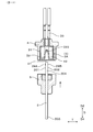
図2に示すように、保持部31は、保持溝42における外周側の端部に配置される本体部分311と、貫通穴43に挿通される延出部分312と、本体部分311と延出部分312とを接続する接続部分313とを有する。本体部分311と延出部分312とは、互いに平行な状態で、挿入方向Dに直交する方向にオフセットして形成されている。アーム部32は、保持部31の本体部分311に繋がる曲線部分321と、曲線部分321に繋がる直線部分322と、直線部分322に設けられて端子接触部28A,28Bに接触する接触部分323とを有する。接触部分323は、曲線状に形成されている。
アーム部32は、主に曲線部分321が曲率半径を小さくするように弾性変形することによって、直線部分322及び接触部分323が保持部31の本体部分311に近づくようにして撓む。また、アーム部32は、曲線部分321を除くアーム部32の全体が反ることによっても撓む。アーム部32が端子接触部28A,28Bに接触して撓んだときには、アーム部32が元の状態に戻ろうとするバネ復元力が端子接触部28A,28Bに作用する。
図1及び図2に示すように、バネ用インシュレータ4の貫通穴43に挿通された、バネ端子3の保持部31の延出部分312には、バネ用インシュレータ4の基端側から端子金具33が装着されている。端子金具33には、ガスセンサ1の外部における制御装置等に接続されるリード線34が取り付けられている。
本形態のバネ端子3は、円形状の断面を有する、線径がφ0.4~0.7mmの範囲内にある丸線材(鋼線)によって構成されている。保持部31及びアーム部32は、丸線材が折り曲げられることによって形成されている。丸線材を用いることにより、強度を確保してバネ端子3を構成する線材の幅を極力小さくすることができる。また、丸線材を用いることにより、バネ用インシュレータ4において複数のバネ端子3が占めるスペースを小さくすることができ、バネ用インシュレータ4の小型化、しいてはガスセンサ1の小型化を図ることができる。
バネ端子3の線径がφ0.4mm未満である場合には、図3に示すように、バネ端子3と、バネ端子3が配置される、バネ用インシュレータ4の保持溝42との隙間Sが大きくなり、バネ端子3が保持溝42において幅方向Wへ位置ずれする量が大きくなる。そのため、センサ素子2における端子接触部28A,28Bの幅方向Wの幅を大きくする必要が生じ、センサ素子2の小型化を妨げる要因となる。
一方、バネ端子3の線径がφ0.7mm超過である場合には、バネ端子3のアーム部32が撓みにくくなり、複数のバネ端子3が保持されたバネ用インシュレータ4の挿入穴41へのセンサ素子2の挿入性が悪化する要因となる。また、バネ端子3が配置される、バネ用インシュレータ4の保持溝42の幅は、バネ用インシュレータ4を成形する成形型の強度を確保する観点から、0.7mm以上であることが好ましい。
なお、バネ端子3の断面形状は、扁平形状、楕円形状、四角形状を含む角形状等であってもよい。この場合、バネ端子3の断面における長径部(長辺部)の長さと短径部(短辺部)の長さとの比であるアスペクト比は、1:1~1:2の範囲内になるようにすることができる。
図3に示すように、傾斜バネ端子3Aは、幅方向Wに並んで配置されるとともに、センサ素子2を介して互いに向き合う位置に配置されている。また、傾斜バネ端子3Aは、センサ素子2の厚み方向Tの両側において、幅方向Wに並んで一対に配置されている。傾斜バネ端子3Aは、センサ素子2の基端部204の第1外面201に設けられた2つの第1端子接触部28Aに対応して、第1外面201に対向して幅方向Wに2つ並んで配置されている。また、傾斜バネ端子3Aは、センサ素子2の基端部204の第2外面202に設けられた2つの第2端子接触部28Bに対応して、第2外面202に対向して幅方向Wに2つ並んで配置されている。第1外面201に対向して配置された2つの傾斜バネ端子3Aと、第2外面202に対向して配置された2つの傾斜バネ端子3Aとは、センサ素子2を介して互いに向き合っている。
また、各傾斜バネ端子3Aが傾斜する方向は、アーム部32が保持部31よりもセンサ素子2の幅方向Wの中心側に位置する方向となっている。そして、バネ用インシュレータ4を挿入方向Dから見たときには、4つの傾斜バネ端子3Aが、X形状に近い状態で、センサ素子2の厚み方向Tに対して傾斜して配置されている。
傾斜バネ端子3Aがセンサ素子2を介して互いに向き合っていることにより、図9に示すように、バネ用インシュレータ4の挿入穴41にセンサ素子2が挿入されていない状態においては、厚み方向Tにおいて互いに対向する傾斜バネ端子3Aのアーム部32の接触部分323同士が接触することになる。また、この状態において、アーム部32が保持部31よりもセンサ素子2の幅方向Wの中心側に位置していることにより、互いに対向する傾斜バネ端子3Aのアーム部32の各接触部分323は、いずれも幅方向Wの中心側へ位置ずれすることになる。そのため、傾斜バネ端子3Aのアーム部32同士が幅方向Wの互いに異なる側へ位置ずれすることが防止される。また、アーム部32の接触部分323が、端子接触部28A,28Bから幅方向Wの外方へ位置ずれして、センサ素子2の幅方向Wの外方へ外れることが防止される。同図において、アーム部32の各接触部分323が位置ずれする方向を矢印Pによって示す。
また、各傾斜バネ端子3Aのアーム部32が保持部31よりもセンサ素子2の幅方向Wの中心側に位置していることにより、バネ用インシュレータ4において、複数の傾斜バネ端子3Aをできるだけ放射状に近い状態に配置することができる。これにより、幅方向Wに並ぶ一対の傾斜バネ端子3Aの保持部31同士の間隔を広くすることができる。そのため、傾斜バネ端子3Aに接続される端子金具33同士、及び端子金具33を介して傾斜バネ端子3Aに接続されるリード線34同士の干渉を容易に避けることができる。
図3に示すように、センサ素子2の端子接触部28A,28Bに接触した状態の各傾斜バネ端子3Aのアーム部32は、端子接触部28A,28Bに接触する前の状態に比べて、端子接触部28A,28Bの外面に垂直な垂線Mに対する、撓み方向Fに沿った中心軸線Oの傾斜角度θを大きくする状態で撓んでいる。中心軸線Oとは、挿入方向Dから見たときに、アーム部32の断面の中心を通る仮想線のことをいう。また、この状態においては、傾斜バネ端子3Aのアーム部32は、保持溝42の幅方向Wにおける中心側の側面421に接触して、端子接触部28A,28Bの外面に対する位置が固定されている。
同図に示すように、バネ用インシュレータ4の保持溝42の幅は、バネ端子3の線径よりも大きい。そして、保持溝42とバネ端子3との間には、隙間Sが形成される。これにより、傾斜バネ端子3Aのアーム部32が端子接触部28A,28Bに接触したときには、アーム部32が隙間Sの範囲内において位置ずれする。このとき、傾斜バネ端子3Aの撓み方向Fが端子接触部28A,28Bの外面に対して傾斜していることにより、傾斜バネ端子3Aのアーム部32が位置ずれする方向は、垂線Mに対するアーム部32の中心軸線Oの傾斜角度θが大きくなる方向となる。
そして、アーム部32が保持溝42の幅方向Wにおける中心側の側面421に接触することにより、幅方向Wへのアーム部32の位置ずれが規制される。そして、端子接触部28A,28Bの外面に対するアーム部32の位置が固定される。これにより、端子接触部28A,28Bの外面に対するアーム部32の幅方向Wの位置を安定させることができる。そのため、端子接触部28A,28Bに対する傾斜バネ端子3Aの接触状態を良好に保つことができる。
センサ素子2、及びバネ用インシュレータ4に保持された複数の傾斜バネ端子3Aを挿入方向Dから見たときに、傾斜バネ端子3Aの撓み方向Fに沿った中心軸線Oと、端子接触部28A,28Bの外面に対して垂直な垂線Mとの間の傾斜角度θは、5~45°の範囲内にある。傾斜角度θが5°未満である場合には、傾斜バネ端子3Aのアーム部32の撓み方向Fが端子接触部28A,28Bの外面に対して傾斜することによる効果が得られにくい。一方、傾斜角度θが45°超過である場合には、傾斜バネ端子3Aのアーム部32が端子接触部28A,28Bの外面を滑りやすくなり、傾斜バネ端子3Aと端子接触部28A,28Bとの接触状態が悪化するおそれがある。
また、図9に示すように、幅方向Wに並ぶ2つの傾斜バネ端子3Aは、バネ用インシュレータ4の挿入穴41にセンサ素子2が挿入されていない状態において、幅方向Wに並ぶ2つの傾斜バネ端子3Aのアーム部32同士が接触しない、位置及び傾斜角度で配置されている。幅方向Wに並ぶ2つの傾斜バネ端子3Aのアーム部32同士が接触する場合には、挿入穴41へのセンサ素子2の挿入性が悪化する。また、この場合には、センサ素子2の外面201,202に幅方向Wに並ぶ複数の端子接触部28A,28Bを設けることが困難になる。
次に、本形態のガスセンサ1による作用効果について説明する。
本形態のガスセンサ1においては、丸線材から構成されたバネ端子3を用いるために、センサ素子2の外面201,202における端子接触部28A,28Bに対するバネ端子3の接触状態を良好に保つための工夫をしている。具体的には、バネ端子3のアーム部32に作用させるバネ復元力を、端子接触部28A,28Bの外面に対して、厚み方向Tに傾斜する状態で作用させる。そして、アーム部32の接触部分323が、端子接触部28A,28Bの外面の幅方向Wの中心側にのみ位置ずれ可能な状態を形成する。
本形態のガスセンサ1においては、丸線材から構成されたバネ端子3を用いるために、センサ素子2の外面201,202における端子接触部28A,28Bに対するバネ端子3の接触状態を良好に保つための工夫をしている。具体的には、バネ端子3のアーム部32に作用させるバネ復元力を、端子接触部28A,28Bの外面に対して、厚み方向Tに傾斜する状態で作用させる。そして、アーム部32の接触部分323が、端子接触部28A,28Bの外面の幅方向Wの中心側にのみ位置ずれ可能な状態を形成する。
(素子挿入前の状態)
図9に示すように、バネ用インシュレータ4の挿入穴41にセンサ素子2の基端部204が挿入されていない素子挿入前の状態においては、各傾斜バネ端子3Aのアーム部32同士が、厚み方向Tに対して傾斜する方向へバネ復元力を作用させながら、厚み方向Tにおいて互いに接触している。このとき、各傾斜バネ端子3Aの互いに接触するアーム部32は、バネ復元力の作用により、いずれも幅方向Wの中心側へ位置ずれして位置が決まる。これにより、互いに接触するアーム部32が、幅方向Wの互いに異なる側へ位置ずれすることが防止され、互いに接触するアーム部32が幅方向Wにすれ違うことが防止される。そのため、図10に示すように、バネ用インシュレータ4の挿入穴41へセンサ素子2の基端部204を挿入するときにおいて、アーム部32を円滑に撓ませることができ、挿入穴41へのセンサ素子2の挿入性を良好に保つことができる。
図9に示すように、バネ用インシュレータ4の挿入穴41にセンサ素子2の基端部204が挿入されていない素子挿入前の状態においては、各傾斜バネ端子3Aのアーム部32同士が、厚み方向Tに対して傾斜する方向へバネ復元力を作用させながら、厚み方向Tにおいて互いに接触している。このとき、各傾斜バネ端子3Aの互いに接触するアーム部32は、バネ復元力の作用により、いずれも幅方向Wの中心側へ位置ずれして位置が決まる。これにより、互いに接触するアーム部32が、幅方向Wの互いに異なる側へ位置ずれすることが防止され、互いに接触するアーム部32が幅方向Wにすれ違うことが防止される。そのため、図10に示すように、バネ用インシュレータ4の挿入穴41へセンサ素子2の基端部204を挿入するときにおいて、アーム部32を円滑に撓ませることができ、挿入穴41へのセンサ素子2の挿入性を良好に保つことができる。
仮に、比較形態として、図11に示すように、厚み方向Tにおいて互いに接触する、バネ端子3Xのアーム部32が、厚み方向Tに沿ってバネ復元力を作用させる場合には、バネ端子3Xが丸線材によって構成されるために、各アーム部32が幅方向Wの互いに異なる側へ位置ずれし、幅方向Wにすれ違うおそれがある。同図において、バネ用インシュレータを符号4Xによって示し、保持溝を符号42Xによって示す。この場合には、バネ用インシュレータ4Xの挿入穴41へセンサ素子2の基端部204を挿入するときにおいて、アーム部32が円滑に撓むことができないおそれがあり、挿入穴41へのセンサ素子2の挿入性を悪化させるおそれがある。
(素子挿入後の状態)
図3に示すように、バネ用インシュレータ4の挿入穴41にセンサ素子2の基端部204が挿入された素子挿入後の状態においては、各傾斜バネ端子3Aのアーム部32の接触部分323は、端子接触部28A,28Bの外面に対して幅方向Wの中心側にのみ位置ずれしている。各アーム部32は、各アーム部32の中心軸線Oと垂線Mとの間の傾斜角度θが大きくなるように位置ずれしている。同図において、アーム部32の各接触部分323が位置ずれする方向を矢印Pによって示す。
図3に示すように、バネ用インシュレータ4の挿入穴41にセンサ素子2の基端部204が挿入された素子挿入後の状態においては、各傾斜バネ端子3Aのアーム部32の接触部分323は、端子接触部28A,28Bの外面に対して幅方向Wの中心側にのみ位置ずれしている。各アーム部32は、各アーム部32の中心軸線Oと垂線Mとの間の傾斜角度θが大きくなるように位置ずれしている。同図において、アーム部32の各接触部分323が位置ずれする方向を矢印Pによって示す。
また、各傾斜バネ端子3Aのアーム部32は、バネ用インシュレータ4の保持溝42の幅方向Wにおける中心側の側面421に接触する。これにより、アーム部32の接触部分323が位置ずれする方向及び位置ずれする量が規制され、アーム部32の接触部分323が端子接触部28A,28Bの外面に接触する位置が定まる。そのため、端子接触部28A,28Bに対するアーム部32の接触位置が定まり、アーム部32と端子接触部28A,28Bとの間に接触不良が生じにくくすることができる。
仮に、比較形態として、図12に示すように、厚み方向Tにおいて互いに接触する、バネ端子3Xのアーム部32が、厚み方向Tに沿ってバネ復元力を作用させる場合には、アーム部32が幅方向Wのいずれの側へ位置ずれするかが定まらない。同図において、アーム部32の各接触部分323が位置ずれする方向が定まらない状態を符号Qによって示す。これにより、アーム部32の接触部分323が端子接触部28A,28Bの外面に接触する位置にばらつきが生じる。そのため、端子接触部28A,28Bに対するアーム部32の接触位置が定まりにくく、アーム部32と端子接触部28A,28Bとの間に接触不良が生じるおそれがある。
このように、本形態の傾斜バネ端子3Aの接触構造を有するガスセンサ1によれば、バネ用インシュレータ4の挿入穴41へのセンサ素子2の、素子挿入前の状態及び素子挿入後の状態のいずれにおいても、傾斜バネ端子3Aの状態を適切に保つことができる。それ故、本形態のガスセンサ1によれば、バネ端子3とセンサ素子2との間の電気接続の状態を良好にすることができる。
また、センサ素子2にヒータ23が積層されない場合には、第2端子接触部28B及び第2端子接触部28Bに接触する傾斜バネ端子3Aが不要になる。この場合には、図13に示すように、第1端子接触部28Aをセンサ素子2の第1外面201に形成し、傾斜バネ端子3Aは、センサ素子2の第1外面201の第1端子接触部28Aに接触する2つのみとすることもできる。
<実施形態2>
本形態は、バネ用インシュレータ4におけるバネ端子3の保持数が6つである場合について示す。
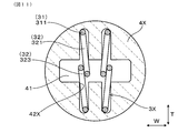
図14に示すように、本形態のバネ用インシュレータ4には、4つの傾斜バネ端子3Aの他に、2つの垂直バネ端子3Bが保持される。垂直バネ端子3Bは、バネ用インシュレータ4に保持される複数のバネ端子3のうちの傾斜バネ端子3A以外のバネ端子3である。
本形態は、バネ用インシュレータ4におけるバネ端子3の保持数が6つである場合について示す。
図14に示すように、本形態のバネ用インシュレータ4には、4つの傾斜バネ端子3Aの他に、2つの垂直バネ端子3Bが保持される。垂直バネ端子3Bは、バネ用インシュレータ4に保持される複数のバネ端子3のうちの傾斜バネ端子3A以外のバネ端子3である。
垂直バネ端子3Bは、幅方向Wに並ぶ一対の傾斜バネ端子3Aの間において、アーム部32の撓み方向Fが端子接触部28A,28Bの外面に対して垂直になる状態で配置されている。バネ用インシュレータ4には、厚み方向Tに傾斜する傾斜バネ端子3A用の保持溝42Aと、厚み方向Tに平行な垂直バネ端子3B用の保持溝42Bとが形成されている。
本形態のバネ端子3は、センサ素子2に設けられた電極の数が4つであり、かつヒータ23の発熱体230のリード部232が2つであることによって、合計6つが使用される。本形態のガスセンサ1は、例えば、NOx(窒素酸化物)等の特定ガス成分の濃度を検出するNOxセンサとすることができる。NOxセンサのセンサ素子2においては、ガス室26における排ガスG中の酸素を排出するために固体電解質体21の第1主面211に設けられたポンプ電極と、ガス室26における排ガスGの残留酸素濃度を検出するために固体電解質体21の第1主面211に設けられたモニタ電極と、ガス室26における排ガスGのNOx濃度を検出するために固体電解質体21の第1主面211に設けられたセンサ電極と、固体電解質体21の第2主面212に設けられた、大気Aに晒される基準電極との4つの電極が用いられる。また、センサ素子2には、ヒータ23が積層されている。
図15に示すように、センサ素子2の第1外面201及び第2外面202には、それぞれ3つの端子接触部28C,28Dが形成されている。第1外面201には、ポンプ電極、モニタ電極及びセンサ電極のそれぞれのリード部221に繋がる3つの端子接触部28C,28Dが形成されている。第2外面202には、基準電極のリード部221と、ヒータ23の発熱体230のリード部232とにそれぞれ繋がる3つの端子接触部28C,28Dが形成されている。
センサ素子2の各外面201,202に形成された3つの端子接触部28C,28Dには、センサ素子2の基端部204の基端側において幅方向Wに2つ並んで形成された基端側端子接触部28Dと、基端側端子接触部28Dの先端側に隣接して形成された先端側端子接触部28Cとがある。2つの基端側端子接触部28Dには、幅方向Wに並ぶ2つの傾斜バネ端子3Aのアーム部32が接触する。また、先端側端子接触部28Cには、垂直バネ端子3Bのアーム部32が接触する。
図15に示すように、垂直バネ端子3Bと接触する先端側端子接触部28Cの幅方向Wの形成幅は、基端側端子接触部28Dの幅方向Wの形成幅に比べて大きい。これにより、垂直バネ端子3Bのアーム部32の、センサ素子2の幅方向Wのいずれの側への位置ずれも許容することができる。また、ポンプ電極、モニタ電極、センサ電極、基準電極、発熱体230と、傾斜バネ端子3A及び垂直バネ端子3Bとの対応関係は、いずれの対応関係とすることもできる。
本形態のガスセンサ1においては、センサ素子2に用いられる電極の数の増加に応じて、一対の傾斜バネ端子3Aの間に垂直バネ端子3Bを配置している。そして、垂直バネ端子3Bが接触する先端側端子接触部28Cの幅方向Wの形成幅は、傾斜バネ端子3Aが接触する基端側端子接触部28Dの幅方向Wの形成幅よりも大きい。これにより、垂直バネ端子3Bを用いる場合においても、この垂直バネ端子3Bと先端側端子接触部28Cとの接触状態を良好に保つことができる。
なお、NOxセンサのセンサ素子2にヒータ23が積層されない場合には、ポンプ電極、モニタ電極、センサ電極及び基準電極の4つの電極を、センサ素子2の第1外面201及び第2外面202に2つずつ形成された端子接触部28A,28Bと、4つの傾斜バネ端子3Aとに対応させることができる。
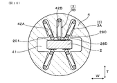
また、図16に示すように、垂直バネ端子3Bは、センサ素子2の第1外面201においてのみ用い、ガスセンサ1においては、合計5つのバネ端子3を用いることもできる。
また、図16に示すように、垂直バネ端子3Bは、センサ素子2の第1外面201においてのみ用い、ガスセンサ1においては、合計5つのバネ端子3を用いることもできる。
本形態のガスセンサ1におけるその他の構成、作用効果等については、実施形態1の場合と同様である。また、本形態においても、実施形態1に示した符号と同一の符号が示す構成要素は、実施形態1の場合と同様である。
<実施形態3>
本形態は、バネ用インシュレータ4における保持溝42の変形例について示す。
保持溝42は、図17に示すように、バネ用インシュレータ4の先端側の端面から基端側へ連続して形成するのではなく、バネ用インシュレータ4の先端側部分に形成された凹部44から基端側に向けて形成されていてもよい。
本形態は、バネ用インシュレータ4における保持溝42の変形例について示す。
保持溝42は、図17に示すように、バネ用インシュレータ4の先端側の端面から基端側へ連続して形成するのではなく、バネ用インシュレータ4の先端側部分に形成された凹部44から基端側に向けて形成されていてもよい。
また、保持溝42は、挿入方向Dから見た状態において直線状に形成する以外にも、図18及び図19に示すように、挿入方向Dから見た状態において段差状に形成することもできる。段差状の保持溝42は、傾斜バネ端子3Aがセンサ素子2の厚み方向Tに対して傾斜して配置されるように形成する。傾斜バネ端子3Aの保持部31は、段差状の保持溝42の幅方向Wにおける外側の角部に配置される。傾斜バネ端子3Aのアーム部32は、保持部31から幅方向Wの中心側に向けて配置される。
図18には、保持溝42における、厚み方向Tの中心側に位置する部分422の幅方向Wの幅を、保持溝42における、厚み方向Tの外側に位置する部分423の幅方向Wの幅よりも小さくした例を示す。また、図19には、保持溝42における、厚み方向Tの中心側に位置する部分422を、保持溝42における、厚み方向Tの外側に位置する部分423よりも幅方向Wの中心側に形成した例を示す。これらの段差状の保持溝42の形成により、傾斜バネ端子3Aを、端子接触部28A,28Bの外面に対して傾斜させることができる。
本形態のガスセンサ1におけるその他の構成、作用効果等については、実施形態1の場合と同様である。また、本形態においても、実施形態1に示した符号と同一の符号が示す構成要素は、実施形態1の場合と同様である。
<実施形態4>
本形態は、バネ端子3の形状の変形例について示す。
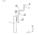
バネ端子3の保持部31は、撓み方向Fにおける位置がオフセットするように屈曲して形成する以外にも、図20に示すように、挿入方向Dに平行な直線状に形成することもできる。また、アーム部32は、保持部31から挿入方向Dに折り返して形成する以外にも、図21に示すように、保持部31の挿入方向Dの先端側の端部から、先端側へ延設する状態で形成することもできる。また、小型化には反することになるが、図22に示すように、アーム部32は、保持部31の挿入方向Dの先端側の端部から基端側へ折り返し、さらに先端側に折り返す形状に形成することもできる。
本形態は、バネ端子3の形状の変形例について示す。
バネ端子3の保持部31は、撓み方向Fにおける位置がオフセットするように屈曲して形成する以外にも、図20に示すように、挿入方向Dに平行な直線状に形成することもできる。また、アーム部32は、保持部31から挿入方向Dに折り返して形成する以外にも、図21に示すように、保持部31の挿入方向Dの先端側の端部から、先端側へ延設する状態で形成することもできる。また、小型化には反することになるが、図22に示すように、アーム部32は、保持部31の挿入方向Dの先端側の端部から基端側へ折り返し、さらに先端側に折り返す形状に形成することもできる。
図20~図22においては、センサ素子2の片側の外面に配置されたバネ端子3について示す。バネ端子3は、センサ素子2の両側の外面に配置されていてもよい。
本形態のガスセンサ1におけるその他の構成、作用効果等については、実施形態1の場合と同様である。また、本形態においても、実施形態1に示した符号と同一の符号が示す構成要素は、実施形態1の場合と同様である。
本形態のガスセンサ1におけるその他の構成、作用効果等については、実施形態1の場合と同様である。また、本形態においても、実施形態1に示した符号と同一の符号が示す構成要素は、実施形態1の場合と同様である。
また、ガスセンサ1においてバネ端子3を用いる数は、センサ素子2に設けられる電極の数に合わせて適宜変更することができる。また、ガスセンサ1において2枚の固体電解質体21を用い、ポンプ電極が形成される固体電解質体21と、モニタ電極及びセンサ電極が形成される固体電解質体21とを別のものとしてもよい。また、各実施形態に示す構造は、大気ダクト27が形成されていないセンサ素子2に対して適用することもできる。
本開示は、各実施形態のみに限定されるものではなく、その要旨を逸脱しない範囲においてさらに異なる実施形態を構成することが可能である。また、本開示は、様々な変形例、均等範囲内の変形例等を含む。さらに、本開示から想定される様々な構成要素の組み合わせ、形態等も本開示の技術思想に含まれる。
Claims (9)
- 端子接触部(28A,28B,28C,28D)が基端部(204)の外面(201,202)に複数設けられ、ガス検出を行うためのセンサ素子(2)と、
屈曲する線材によって構成された複数のバネ端子(3)と、
前記センサ素子の前記基端部が挿入された挿入穴(41)、及び前記挿入穴に連通された複数の保持溝(42)を有するインシュレータ(4)と、を備えるガスセンサ(1)において、
前記バネ端子は、前記保持溝内に保持される保持部(31)と、前記保持部から延設され、前記保持部に対して撓んで前記端子接触部に接触するアーム部(32)とを有しており、
前記挿入穴への前記センサ素子の挿入方向(D)から見たときに、複数の前記バネ端子のうちの少なくとも1つである傾斜バネ端子(3A)における、前記保持部に対する前記アーム部の撓み方向(F)は、前記端子接触部の外面に対して傾斜している、ガスセンサ。 - 前記端子接触部は、前記挿入方向に直交する幅方向(W)に複数並んで設けられており、
前記傾斜バネ端子は、前記幅方向に並んで配置されており、
前記傾斜バネ端子の前記アーム部は、前記保持部よりも前記センサ素子の前記幅方向の中心側に位置する、請求項1に記載のガスセンサ。 - 前記傾斜バネ端子の前記アーム部は、前記端子接触部の外面に垂直な垂線(M)に対する、前記撓み方向に沿った中心軸線(O)の傾斜角度(θ)を大きくする状態で撓み、かつ、前記保持溝の前記幅方向における中心側の側面(421)に接触して、前記端子接触部の外面に対する位置が固定されている、請求項2に記載のガスセンサ。
- 前記端子接触部は、前記センサ素子の、前記挿入方向と前記幅方向とに直交する厚み方向(T)の両側に設けられており、
前記傾斜バネ端子は、前記センサ素子を介して互いに向き合う位置に配置されている、請求項2又は3に記載のガスセンサ。 - 前記傾斜バネ端子は、前記センサ素子の前記厚み方向の両側において、前記幅方向に並んで一対に配置されており、
複数の前記バネ端子のうちの前記傾斜バネ端子以外のバネ端子である垂直バネ端子(3B)は、前記幅方向に並ぶ一対の前記傾斜バネ端子の間において、前記アーム部の前記撓み方向が前記端子接触部の外面に対して垂直になる状態で配置されている、請求項2~4のいずれか1項に記載のガスセンサ。 - 前記センサ素子は、少なくとも一対の電極(22A,22B)が設けられた固体電解質体(21)と、前記固体電解質体に積層されたヒータ(23)とを有しており、
複数の前記端子接触部には、前記電極に繋がる第1端子接触部(28A)と、前記ヒータの発熱体(230)に繋がる第2端子接触部(28B)とが含まれる、請求項2~5のいずれか1項に記載のガスセンサ。 - 前記挿入方向から見たときに、前記傾斜バネ端子の前記撓み方向に沿った中心軸線(O)と、前記端子接触部の外面に対して垂直な垂線(M)との間の傾斜角度(θ)は、5~45°の範囲内にある、請求項2~6のいずれか1項に記載のガスセンサ。
- 複数の前記バネ端子は、円形状の断面を有する、線径がφ0.4~0.7mmの範囲内にある丸線材によって構成されている、請求項1~7のいずれか1項に記載のガスセンサ。
- 前記アーム部は、前記保持部から折り返されて前記保持部と対向している、請求項1~8のいずれか1項に記載のガスセンサ。
Priority Applications (3)
| Application Number | Priority Date | Filing Date | Title |
|---|---|---|---|
| DE112018004919.1T DE112018004919T5 (de) | 2017-08-31 | 2018-08-27 | Gassensor |
| CN201880055704.5A CN111051872B (zh) | 2017-08-31 | 2018-08-27 | 气体传感器 |
| US16/799,998 US20200191743A1 (en) | 2017-08-31 | 2020-02-25 | Gas sensor |
Applications Claiming Priority (2)
| Application Number | Priority Date | Filing Date | Title |
|---|---|---|---|
| JP2017167558A JP6747407B2 (ja) | 2017-08-31 | 2017-08-31 | ガスセンサ |
| JP2017-167558 | 2017-08-31 |
Related Child Applications (1)
| Application Number | Title | Priority Date | Filing Date |
|---|---|---|---|
| US16/799,998 Continuation US20200191743A1 (en) | 2017-08-31 | 2020-02-25 | Gas sensor |
Publications (1)
| Publication Number | Publication Date |
|---|---|
| WO2019044746A1 true WO2019044746A1 (ja) | 2019-03-07 |
Family
ID=65527508
Family Applications (1)
| Application Number | Title | Priority Date | Filing Date |
|---|---|---|---|
| PCT/JP2018/031518 WO2019044746A1 (ja) | 2017-08-31 | 2018-08-27 | ガスセンサ |
Country Status (5)
| Country | Link |
|---|---|
| US (1) | US20200191743A1 (ja) |
| JP (1) | JP6747407B2 (ja) |
| CN (1) | CN111051872B (ja) |
| DE (1) | DE112018004919T5 (ja) |
| WO (1) | WO2019044746A1 (ja) |
Cited By (3)
| Publication number | Priority date | Publication date | Assignee | Title |
|---|---|---|---|---|
| JP2021032785A (ja) * | 2019-08-28 | 2021-03-01 | 日本碍子株式会社 | ガスセンサ |
| WO2022024583A1 (ja) * | 2020-07-31 | 2022-02-03 | 株式会社デンソー | ガスセンサ |
| US11594481B2 (en) * | 2020-08-27 | 2023-02-28 | Infineon Technologies Ag | Package, method for forming a package, carrier tape, chip card and method for forming a carrier tape |
Families Citing this family (2)
| Publication number | Priority date | Publication date | Assignee | Title |
|---|---|---|---|---|
| JP7349300B2 (ja) * | 2019-09-17 | 2023-09-22 | 日本碍子株式会社 | ガスセンサ |
| JP2022061111A (ja) * | 2020-10-06 | 2022-04-18 | 日本特殊陶業株式会社 | ガスセンサ |
Citations (5)
| Publication number | Priority date | Publication date | Assignee | Title |
|---|---|---|---|---|
| JPH09512912A (ja) * | 1994-05-05 | 1997-12-22 | ロト テヒニク ゲーエムベーハー ウント コー フォルシュンク フュア アウトモビル ウント ウンベルトテヒニク | ガスセンサ |
| JP2001188060A (ja) * | 1999-10-19 | 2001-07-10 | Denso Corp | ガスセンサ |
| JP2001343356A (ja) * | 2000-03-30 | 2001-12-14 | Denso Corp | ガスセンサ |
| JP2006337096A (ja) * | 2005-05-31 | 2006-12-14 | Ngk Spark Plug Co Ltd | センサ |
| JP2012230076A (ja) * | 2011-04-27 | 2012-11-22 | Ngk Spark Plug Co Ltd | センサ |
Family Cites Families (7)
| Publication number | Priority date | Publication date | Assignee | Title |
|---|---|---|---|---|
| DE60045025D1 (de) * | 1999-08-30 | 2010-11-11 | Denso Corp | Gassensor |
| JP2004264262A (ja) * | 2003-03-04 | 2004-09-24 | Denso Corp | セラミック素子と摺動端子との摺動接触構造 |
| JP5509234B2 (ja) * | 2012-02-29 | 2014-06-04 | 日本特殊陶業株式会社 | ガスセンサ |
| JP2015145831A (ja) * | 2014-02-03 | 2015-08-13 | 株式会社デンソー | ガスセンサ |
| JP6331891B2 (ja) * | 2014-08-29 | 2018-05-30 | 株式会社デンソー | ガスセンサ |
| JP6500769B2 (ja) * | 2015-12-21 | 2019-04-17 | 株式会社デンソー | センサ |
| JP2017167558A (ja) | 2017-05-22 | 2017-09-21 | オプリンク コミュニケーションズ エルエルシー | Memsファイバ光スイッチ |
-
2017
- 2017-08-31 JP JP2017167558A patent/JP6747407B2/ja active Active
-
2018
- 2018-08-27 CN CN201880055704.5A patent/CN111051872B/zh active Active
- 2018-08-27 WO PCT/JP2018/031518 patent/WO2019044746A1/ja active Application Filing
- 2018-08-27 DE DE112018004919.1T patent/DE112018004919T5/de active Pending
-
2020
- 2020-02-25 US US16/799,998 patent/US20200191743A1/en active Pending
Patent Citations (5)
| Publication number | Priority date | Publication date | Assignee | Title |
|---|---|---|---|---|
| JPH09512912A (ja) * | 1994-05-05 | 1997-12-22 | ロト テヒニク ゲーエムベーハー ウント コー フォルシュンク フュア アウトモビル ウント ウンベルトテヒニク | ガスセンサ |
| JP2001188060A (ja) * | 1999-10-19 | 2001-07-10 | Denso Corp | ガスセンサ |
| JP2001343356A (ja) * | 2000-03-30 | 2001-12-14 | Denso Corp | ガスセンサ |
| JP2006337096A (ja) * | 2005-05-31 | 2006-12-14 | Ngk Spark Plug Co Ltd | センサ |
| JP2012230076A (ja) * | 2011-04-27 | 2012-11-22 | Ngk Spark Plug Co Ltd | センサ |
Cited By (5)
| Publication number | Priority date | Publication date | Assignee | Title |
|---|---|---|---|---|
| JP2021032785A (ja) * | 2019-08-28 | 2021-03-01 | 日本碍子株式会社 | ガスセンサ |
| US11585781B2 (en) | 2019-08-28 | 2023-02-21 | Ngk Insulators, Ltd. | Gas sensor |
| JP7242478B2 (ja) | 2019-08-28 | 2023-03-20 | 日本碍子株式会社 | ガスセンサ |
| WO2022024583A1 (ja) * | 2020-07-31 | 2022-02-03 | 株式会社デンソー | ガスセンサ |
| US11594481B2 (en) * | 2020-08-27 | 2023-02-28 | Infineon Technologies Ag | Package, method for forming a package, carrier tape, chip card and method for forming a carrier tape |
Also Published As
| Publication number | Publication date |
|---|---|
| DE112018004919T5 (de) | 2020-07-02 |
| CN111051872A (zh) | 2020-04-21 |
| JP2019045260A (ja) | 2019-03-22 |
| US20200191743A1 (en) | 2020-06-18 |
| JP6747407B2 (ja) | 2020-08-26 |
| CN111051872B (zh) | 2023-04-04 |
Similar Documents
| Publication | Publication Date | Title |
|---|---|---|
| WO2019044746A1 (ja) | ガスセンサ | |
| JP4474752B2 (ja) | ガスセンサ | |
| US10514356B2 (en) | Gas sensor | |
| US20220065809A1 (en) | Gas sensor | |
| JP6568009B2 (ja) | ガスセンサ | |
| US10451583B2 (en) | Gas sensor | |
| EP1394536A1 (en) | Gas sensor and structure of electric connector | |
| JP4461585B2 (ja) | ガスセンサ | |
| US10502704B2 (en) | Gas sensor provided with flange portion of cover thereof | |
| US10481122B2 (en) | Gas sensor element and gas sensor | |
| US9541533B2 (en) | Gas sensor | |
| JP4527626B2 (ja) | ガスセンサ素子及びガスセンサ | |
| US20190178835A1 (en) | Gas sensor | |
| JP7432542B2 (ja) | ガスセンサ | |
| JP5836350B2 (ja) | ガスセンサ | |
| JP7186131B2 (ja) | ガスセンサ | |
| JP5886221B2 (ja) | ガスセンサ | |
| JP6379900B2 (ja) | ガスセンサ | |
| JP6438851B2 (ja) | ガスセンサ素子及びガスセンサ | |
| JP7413989B2 (ja) | ガスセンサ | |
| WO2023199691A1 (ja) | ガスセンサ | |
| JP6406161B2 (ja) | ガスセンサ | |
| US20230074136A1 (en) | Gas sensor | |
| JP3861775B2 (ja) | ガスセンサ | |
| JP2022064065A (ja) | ガスセンサ |
Legal Events
| Date | Code | Title | Description |
|---|---|---|---|
| 121 | Ep: the epo has been informed by wipo that ep was designated in this application |
Ref document number: 18850457 Country of ref document: EP Kind code of ref document: A1 |
|
| 122 | Ep: pct application non-entry in european phase |
Ref document number: 18850457 Country of ref document: EP Kind code of ref document: A1 |