WO2019026545A1 - トルク監視装置および内燃機関制御システム - Google Patents
トルク監視装置および内燃機関制御システム Download PDFInfo
- Publication number
- WO2019026545A1 WO2019026545A1 PCT/JP2018/025697 JP2018025697W WO2019026545A1 WO 2019026545 A1 WO2019026545 A1 WO 2019026545A1 JP 2018025697 W JP2018025697 W JP 2018025697W WO 2019026545 A1 WO2019026545 A1 WO 2019026545A1
- Authority
- WO
- WIPO (PCT)
- Prior art keywords
- torque
- value
- internal combustion
- combustion engine
- engine
- Prior art date
- Legal status (The legal status is an assumption and is not a legal conclusion. Google has not performed a legal analysis and makes no representation as to the accuracy of the status listed.)
- Ceased
Links
Images


Classifications
-
- F—MECHANICAL ENGINEERING; LIGHTING; HEATING; WEAPONS; BLASTING
- F02—COMBUSTION ENGINES; HOT-GAS OR COMBUSTION-PRODUCT ENGINE PLANTS
- F02D—CONTROLLING COMBUSTION ENGINES
- F02D41/00—Electrical control of supply of combustible mixture or its constituents
- F02D41/22—Safety or indicating devices for abnormal conditions
-
- F—MECHANICAL ENGINEERING; LIGHTING; HEATING; WEAPONS; BLASTING
- F02—COMBUSTION ENGINES; HOT-GAS OR COMBUSTION-PRODUCT ENGINE PLANTS
- F02D—CONTROLLING COMBUSTION ENGINES
- F02D2200/00—Input parameters for engine control
- F02D2200/02—Input parameters for engine control the parameters being related to the engine
- F02D2200/10—Parameters related to the engine output, e.g. engine torque or engine speed
- F02D2200/1002—Output torque
- F02D2200/1004—Estimation of the output torque
-
- F—MECHANICAL ENGINEERING; LIGHTING; HEATING; WEAPONS; BLASTING
- F02—COMBUSTION ENGINES; HOT-GAS OR COMBUSTION-PRODUCT ENGINE PLANTS
- F02D—CONTROLLING COMBUSTION ENGINES
- F02D2200/00—Input parameters for engine control
- F02D2200/50—Input parameters for engine control said parameters being related to the vehicle or its components
- F02D2200/501—Vehicle speed
-
- F—MECHANICAL ENGINEERING; LIGHTING; HEATING; WEAPONS; BLASTING
- F02—COMBUSTION ENGINES; HOT-GAS OR COMBUSTION-PRODUCT ENGINE PLANTS
- F02D—CONTROLLING COMBUSTION ENGINES
- F02D2250/00—Engine control related to specific problems or objectives
- F02D2250/18—Control of the engine output torque
-
- F—MECHANICAL ENGINEERING; LIGHTING; HEATING; WEAPONS; BLASTING
- F02—COMBUSTION ENGINES; HOT-GAS OR COMBUSTION-PRODUCT ENGINE PLANTS
- F02D—CONTROLLING COMBUSTION ENGINES
- F02D2250/00—Engine control related to specific problems or objectives
- F02D2250/18—Control of the engine output torque
- F02D2250/22—Control of the engine output torque by keeping a torque reserve, i.e. with temporarily reduced drive train or engine efficiency
-
- F—MECHANICAL ENGINEERING; LIGHTING; HEATING; WEAPONS; BLASTING
- F02—COMBUSTION ENGINES; HOT-GAS OR COMBUSTION-PRODUCT ENGINE PLANTS
- F02D—CONTROLLING COMBUSTION ENGINES
- F02D41/00—Electrical control of supply of combustible mixture or its constituents
- F02D41/02—Circuit arrangements for generating control signals
- F02D41/021—Introducing corrections for particular conditions exterior to the engine
- F02D41/0215—Introducing corrections for particular conditions exterior to the engine in relation with elements of the transmission
- F02D41/0225—Introducing corrections for particular conditions exterior to the engine in relation with elements of the transmission in relation with the gear ratio or shift lever position
-
- F—MECHANICAL ENGINEERING; LIGHTING; HEATING; WEAPONS; BLASTING
- F02—COMBUSTION ENGINES; HOT-GAS OR COMBUSTION-PRODUCT ENGINE PLANTS
- F02D—CONTROLLING COMBUSTION ENGINES
- F02D41/00—Electrical control of supply of combustible mixture or its constituents
- F02D41/02—Circuit arrangements for generating control signals
- F02D41/021—Introducing corrections for particular conditions exterior to the engine
- F02D41/0235—Introducing corrections for particular conditions exterior to the engine in relation with the state of the exhaust gas treating apparatus
- F02D41/024—Introducing corrections for particular conditions exterior to the engine in relation with the state of the exhaust gas treating apparatus to increase temperature of the exhaust gas treating apparatus
- F02D41/0255—Introducing corrections for particular conditions exterior to the engine in relation with the state of the exhaust gas treating apparatus to increase temperature of the exhaust gas treating apparatus to accelerate the warming-up of the exhaust gas treating apparatus at engine start
-
- Y—GENERAL TAGGING OF NEW TECHNOLOGICAL DEVELOPMENTS; GENERAL TAGGING OF CROSS-SECTIONAL TECHNOLOGIES SPANNING OVER SEVERAL SECTIONS OF THE IPC; TECHNICAL SUBJECTS COVERED BY FORMER USPC CROSS-REFERENCE ART COLLECTIONS [XRACs] AND DIGESTS
- Y02—TECHNOLOGIES OR APPLICATIONS FOR MITIGATION OR ADAPTATION AGAINST CLIMATE CHANGE
- Y02T—CLIMATE CHANGE MITIGATION TECHNOLOGIES RELATED TO TRANSPORTATION
- Y02T10/00—Road transport of goods or passengers
- Y02T10/10—Internal combustion engine [ICE] based vehicles
- Y02T10/40—Engine management systems
Definitions
- the disclosure in this specification relates to a torque monitoring device that monitors a torque abnormality of an internal combustion engine, and an internal combustion engine control system.
- Patent Document 1 discloses a torque monitoring device that monitors whether or not an actual torque of an internal combustion engine is in an abnormal torque state that is different from an engine required torque required of the internal combustion engine.
- the present inventor determines that torque abnormality is present when the above-described state in which the amount of deviation between the actual torque and the engine required torque is equal to or more than a predetermined amount continues for a predetermined time (determination time) or more. It was investigated. However, if the determination time is set short, it may be determined that the torque is abnormal even when the amount of deviation temporarily increases due to noise or the like. On the other hand, if the determination time is set long, torque abnormality can not be detected promptly.
- An object of the present disclosure is to provide a torque monitoring device that achieves both the erroneous determination suppression of torque abnormality and the rapid detection.
- a torque monitoring device monitors a torque that monitors whether or not an estimated torque that is an estimated value of an actual torque of an internal combustion engine deviates from an engine required torque required for the internal combustion engine.
- a monitoring device comprising: a count value setting unit that sets a count value to a larger value as a deviation amount between an estimated torque and an engine request torque increases, and an integration unit that calculates an integration value that is a value obtained by integrating count values.
- an abnormality determination unit that determines that the torque is in an abnormal state when the integrated value is equal to or greater than a predetermined abnormality determination threshold.
- the larger the deviation between the estimated torque and the engine required torque the larger the count value is set, and the integrated value of the count value exceeds a predetermined abnormality determination threshold value. It is determined that the torque is in an abnormal state. Therefore, the larger the deviation amount, the easier it is to be judged as a torque abnormal state, the torque abnormality can be detected quickly, and the smaller the deviation amount is, the harder it becomes to be judged as a torque abnormal state. Can be reduced.
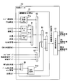
- FIG. 1 is a block diagram of an internal combustion engine control system according to a first embodiment
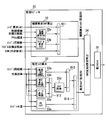
- 2 is a block diagram of the control module shown in FIG. 3 is a block diagram of the monitoring module shown in FIG.
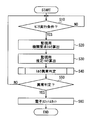
- FIG. 4 is a flowchart showing a procedure of torque monitoring control in the first embodiment
- FIG. 5 is a block diagram showing details of the torque comparison abnormality determination unit of FIG. 3
- FIG. 6 is a map showing the relationship between the dead zone and the gear position used for setting the dead zone in FIG.
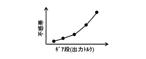
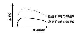
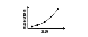
- FIG. 7 is a characteristic diagram showing the relationship between the gear position and the traveling acceleration
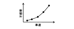
- FIG. 8 is a map showing the relationship between the dead zone and the vehicle speed, which is used for setting the dead zone in FIG.
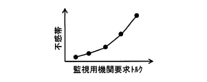
- FIG. 9 is a map showing the relationship between the dead zone and the engine required torque, which is used for setting the dead zone in FIG.
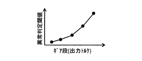
- FIG. 10 is a map showing the relationship between the abnormality determination threshold and the gear, which is used to set the abnormality determination threshold in FIG.
- FIG. 11 is a map showing the relationship between the abnormality determination threshold and the vehicle speed, which is used to set the abnormality determination threshold in FIG.
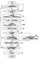
- FIG. 12 is a flowchart showing a processing procedure of torque abnormality determination shown in FIG.
- FIG. 13 is a time chart showing the transition of calculation results of the control module and the monitoring module with respect to the transition of the operating state of the internal combustion engine in the first embodiment
- FIG. 14 is a time chart explaining the operation and effect according to the first embodiment.
- FIG. 1 shows an electronic control unit (ECU) mounted on a vehicle, which controls the operation of an internal combustion engine mounted on the vehicle.
- the vehicle travels with an internal combustion engine as a drive source.
- the internal combustion engine according to the present embodiment is an ignition ignition gasoline engine, but may be a self-ignition diesel engine.
- the vehicle is provided with a transmission that converts the rotational speed of the output shaft of the internal combustion engine into a desired rotational speed and outputs it.
- the ECU 10 includes an MCU 11 (Micro Controller Unit), an ignition drive IC 12, a fuel injection valve drive IC 13, a throttle drive IC 14, a communication circuit 15, and an integrated IC 16.
- MCU 11 Micro Controller Unit
- ignition drive IC 12 a fuel injection valve drive IC 13
- throttle drive IC 14 a communication circuit 15
- integrated IC 16 an integrated circuit
- the MCU 11 includes a CPU 11a which is an arithmetic processing unit, a memory 11m which is a storage medium, an input processing circuit 11c, a communication circuit 11d, and a CPU check circuit 11e.
- the MCU 11 includes the CPU 11a, the memory 11m, the input processing circuit 11c, the communication circuit 11d, and the CPU check circuit 11e integrated on one semiconductor chip, but is dispersed and integrated on a plurality of semiconductor chips.
- a plurality of semiconductor chips may be mounted on a common substrate, or a semiconductor chip may be mounted on each of a plurality of substrates.
- each semiconductor chip may be housed in one common housing, or may be housed in separate housings.
- the memory 11 m is a storage medium for storing programs and data, and includes a non-transitional tangible storage medium for non-temporarily storing a program readable by the CPU 11 a.
- the storage medium may be provided by semiconductor memory or a magnetic disk or the like.
- the program stored in the memory 11m when executed by the CPU 11a, causes the ECU 10 to function as the device described in this specification and causes the control device to execute the method described in this specification.
- control device may be provided by software stored in a tangible storage medium and a computer executing the same, only software, only hardware, or a combination thereof.
- control device is provided by an electronic circuit that is hardware, it can be provided by a digital circuit or analog circuit that includes multiple logic circuits.
- the MCU 11 receives various signals such as an engine rotational speed, an accelerator opening degree, an intake manifold pressure, an exhaust pressure, a water temperature, an oil temperature, and an external signal output from an external ECU. These signals are input from the outside of the ECU 10 to the input processing circuit 11c or the communication circuit 11d.
- the engine speed signal is a signal representing the detected value of the crank angle sensor, and based on this detected value, the MCU 11 counts the rotational speed per unit time of the crankshaft (output shaft) of the internal combustion engine, that is, the rotational speed of the output shaft.
- the signal of the accelerator opening is a signal representing the detected value of the accelerator pedal sensor, and the MCU 11 calculates the amount of depression of the accelerator pedal operated by the driver of the vehicle, that is, the user of the internal combustion engine based on this detected value.
- the signal of the intake manifold pressure is a signal representing the detected value of the intake pressure sensor, and the MCU 11 calculates the pressure of the intake air taken into the combustion chamber based on this detected value.
- the exhaust pressure signal is a signal representing the detection value of the exhaust pressure sensor, and the MCU 11 calculates the pressure of the exhaust gas discharged from the combustion chamber based on this detection value.
- the water temperature signal is a signal that represents the detection value of the water temperature sensor, and the MCU 11 calculates the temperature of the water that cools the internal combustion engine based on this detection value.
- the oil temperature signal is a signal representing a detected value of the oil temperature sensor, and the MCU 11 calculates the temperature of the lubricating oil of the internal combustion engine or the hydraulic oil of the hydraulic actuator based on the detected value.
- a signal representing the operating state of an auxiliary device whose drive source is the output shaft of the internal combustion engine can be mentioned.
- the said auxiliary machine it is a refrigerant
- coolant compressor which the air conditioning apparatus which air-conditions a vehicle interior has, Comprising: The compressor which makes an output shaft of an internal combustion engine a drive source is mentioned.
- the ignition drive IC 12 has a switching element for controlling power supply and interruption to an ignition device provided in the internal combustion engine, and the MCU 11 outputs a command signal to the switching element. Specifically, the MCU 11 calculates a target ignition timing, which is a target value of the timing for performing discharge ignition by the ignition device, based on the various signals such as the engine rotation speed described above, and the command signal is calculated according to the calculated target ignition timing. Output to the ignition drive IC12.
- the fuel injection valve drive IC 13 has a switching element for controlling power supply and interruption to the fuel injection valve provided in the internal combustion engine, and the MCU 11 outputs a command signal to the switching element. Specifically, the MCU 11 calculates a target injection amount which is a target value of a period (that is, an injection amount) in which fuel injection is performed by the fuel injection valve based on various signals such as the engine rotation speed described above. The command signal is output to the fuel injection valve drive IC 13 in accordance with.
- the throttle drive IC 14 has a switching element for controlling power supply and disconnection to an electronic throttle valve (charge throttle) provided in the internal combustion engine, and the MCU 11 outputs a command signal to the switching element. Specifically, the MCU 11 calculates a target opening degree which is a target value of the valve opening degree of the screw based on the various signals such as the engine rotation speed described above, and generates a command signal according to the calculated target opening degree. It outputs to the slo drive IC 14.
- a target opening degree which is a target value of the valve opening degree of the screw based on the various signals such as the engine rotation speed described above
- the combustion state of the internal combustion engine is controlled by the ECU 10 controlling the operation of the ignition device, the fuel injection valve, and the throttle.
- the target ignition timing, the target injection amount and the target opening degree calculated by the MCU 11 correspond to a target control amount that is a target value of a control amount for controlling the combustion state of the internal combustion engine.
- the communication circuit 15 outputs various information held by the MCU 11 to the external ECU. For example, a signal of an abnormality flag representing that an abnormality such as a torque abnormality state occurs is output to a display ECU that controls the operation of a display device that the vehicle driver visually recognizes. The display ECU generates a warning display and a warning sound when acquiring the signal of the abnormality flag.
- the integrated IC 16 includes a memory (not shown), a CPU that executes various programs stored in the memory, and the like. Depending on the program executed by the CPU, the integrated IC 16 functions as the microcomputer monitoring unit 16a or functions as the flash cut control unit 16b.
- the CPU check circuit 11e checks whether the CPU 11a and the memory 11m are normal, such as executing a check (for example, parity check) whether the program and data stored in the memory 11m are normal.
- the microcomputer monitoring unit 16a monitors the operation failure of the MCU 11 while referring to the check result of the CPU check circuit 11e.
- the integrated IC 16 executes control of the electrocut, such as restricting the operation of the electrocut.
- control of the electrocut such as restricting the operation of the electrocut.
- the target opening degree is fixed to a predetermined opening degree set in advance, and the output of the internal combustion engine is limited so as to be less than the predetermined output.
- the target opening is made zero and the internal combustion engine is forcibly stopped.
- the throttle cut control unit 16 b outputs a signal for commanding the throttle cut to the throttle drive IC 14.
- the throttle drive IC 14 operates by giving priority to the throttle cut command signal over the command signal output from the MCU 11.
- the MCU 11 has a control module 20 and a monitoring module 30. Each of these modules is a function provided by the common CPU 11a and the memory 11m. That is, the CPU 11 a and the memory 11 m function as the control module 20 when the CPU 11 a is executing the control program stored in the control storage area 20 m of the memory 11 m.
- the CPU 11 a and the memory 11 m function as the monitoring module 30 when the CPU 11 a is executing the monitoring program stored in the monitoring storage area 30 m of the memory 11 m.
- the control storage area 20m and the monitoring storage area 30m are separately set in different areas of the storage area of the memory 11m.
- the control module 20 provides a “control arithmetic device” that calculates various target control amounts described above in accordance with a user request torque which is a drive torque of an internal combustion engine requested by a user.
- the monitoring module 30 monitors whether or not the estimated torque which is an estimated value of the actual torque of the internal combustion engine deviates by a predetermined amount or more from the engine required torque required for the internal combustion engine.
- a computing device is provided.
- the ECU 10 provides a “torque monitoring device” including a control computing device and a monitoring computing device.
- the control module 20 has functions as an engine required torque calculation unit 21 and a drive signal output unit 22.
- the engine required torque calculation unit 21 calculates an engine required torque, which is a torque to be required for the internal combustion engine, based on various signals acquired from the input processing circuit 11c and the communication circuit 11d.
- the drive signal output unit 22 calculates target control amounts such as the target ignition timing, the target injection amount, and the target opening degree described above in accordance with the engine request torque calculated by the engine request torque calculation unit 21. Furthermore, the drive signal output unit 22 outputs various command signals to the actuators such as the ignition drive IC 12, the fuel injection valve drive IC 13 and the throttle drive IC 14 according to the calculated target control amount.
- the engine required torque calculation unit 21 includes a user required torque calculation unit 21 a, a pump loss calculation unit 21 b, a friction loss calculation unit 21 c, a torque efficiency calculation unit 21 d, and calculation units B1 to B6. It has a function.
- the user request torque calculation unit 21a calculates a user request torque based on the engine speed and the accelerator opening degree described above.
- the user request torque is calculated to a larger value as the engine rotational speed is higher and as the accelerator opening degree is larger.
- a map representing the correlation between the engine rotational speed and the accelerator opening degree and the user request torque is stored in advance in the memory 11m, and the user request torque according to the engine rotational speed and the accelerator opening degree is referred to by referring to the map.
- the user request torque calculation unit 21a calculates.
- the pump loss calculating unit 21b calculates a pump loss torque, which is a value obtained by converting the pump loss into a torque, based on the above-described intake manifold pressure and exhaust pressure.
- Pump loss is energy loss due to resistance received from intake and exhaust when the piston of the internal combustion engine reciprocates. As the intake manifold pressure is lower, the pump loss is set to a larger value on the assumption that the intake resistance in the intake stroke of the piston is larger. Further, the pump loss is set to a large value, assuming that the exhaust resistance in the exhaust stroke of the piston is larger as the exhaust pressure is higher.
- a map representing the intake manifold pressure and the correlation between the exhaust pressure and the pump loss is stored in advance in the memory 11m, and the pump loss calculation unit 21b calculates the pump loss according to the intake manifold pressure and the exhaust pressure with reference to the map.
- the friction loss calculation unit 21c calculates friction loss torque which is a value obtained by converting the friction loss into torque based on the water temperature and the oil temperature described above.
- the friction loss is a mechanical energy loss due to the friction with the cylinder when the piston of the internal combustion engine reciprocates.
- the friction loss is set to a large value, assuming that the friction is large, as the water temperature is out of the proper range and becomes low or high. Further, the friction loss is set to a large value, assuming that the viscosity of the lubricating oil or the like is larger as the oil temperature is lower.
- a map representing the correlation between the water temperature and the oil temperature and the friction loss is stored in advance in the memory 11m, and the friction loss calculating unit 21c calculates the friction loss according to the water temperature and the oil temperature with reference to the map. .
- the calculation unit B1 calculates the total loss torque by adding the pump loss calculated by the pump loss calculation unit 21b, the friction loss calculated by the friction loss calculation unit 21c, and the loss torque learning value.
- the calculation unit B2 calculates the loss-included torque by adding the user request torque calculated by the user request torque calculation unit 21a, the total loss torque calculated by the calculation unit B1, and the external request torque.
- a specific example of the externally required torque is, for the purpose of charging the on-vehicle battery, a torque for an increase in power generation such as increasing the amount of power generation by a generator driven by an internal combustion engine.
- the calculation unit B3 calculates a reserve torque by adding a torque corresponding to each of the idle reserve, the catalyst warm-up reserve, and the auxiliary machine reserve. Each reserve torque is set by the control module 20 according to the operating state of the internal combustion engine such as the engine speed, the engine load, and the water temperature.
- the calculating unit B4 calculates the reserve included torque by adding the reserve torque calculated by the calculating unit B3 to the loss-included torque calculated by the calculating unit B2.
- the idle reserve torque is a torque corresponding to the amount of torque increase when performing control for increasing the torque at the time of idle operation of the internal combustion engine to stabilize the combustion.
- the catalyst warm-up reserve torque is the amount of combustion energy used to raise the exhaust gas temperature when performing warm-up control to raise the exhaust gas temperature to raise the temperature of the catalyst for purifying the exhaust gas of the internal combustion engine above the activation temperature. It is a value obtained by converting the loss into torque.
- the accessory reserve torque is a torque required to drive an accessory such as a generator whose drive source is an internal combustion engine.
- the torque efficiency calculation unit 21 d calculates the torque efficiency based on the maximum torque generation ignition timing (MBT ignition timing), the knock learning included base retardation amount and the target lambda.
- MBT ignition timing is an ignition timing at which the maximum torque can be obtained, and is different depending on the engine speed, the engine load, the water temperature, and the like.
- knocking is apt to occur at the MBT ignition timing, it is required to ignite at a timing that is a predetermined time later than the MBT ignition timing, that is, a timing at which the predetermined angle is retarded.
- the retarded timing is called base ignition timing.
- the retardation amount (base retardation amount) differs depending on the engine speed, the engine load, the water temperature, and the like.
- knock learning amount is used for the ignition timing from the next time on. Learning control to be reflected in control is called knock learning. Then, the timing at which the knocking learning amount is reflected in the base ignition timing corresponds to the target ignition timing.
- the calculation unit B5 calculates a timing obtained by subtracting the target ignition timing from the MBT ignition timing as an MBT retardation amount that is a retardation amount of the target ignition timing with respect to the MBT ignition timing.
- the torque efficiency calculation unit 21d calculates torque efficiency based on the MBT retardation amount calculated by the calculation unit B5 and the target lambda.
- the torque efficiency is the ratio of the energy to be converted to the rotational torque of the crankshaft among the combustion energy in the combustion chamber. As the MBT retardation amount is smaller, that is, as the target ignition timing is closer to the MBT ignition timing, the torque efficiency is calculated to a higher value.
- the target lambda is the target value of the ratio of air to fuel (lambda) included in the mixture that burns in the combustion chamber, and the torque efficiency calculator 21 d calculates torque efficiency to a value according to the target lambda. Do.
- a map representing the MBT retardation amount and the correlation between the target lambda and the torque efficiency is stored in advance in the memory 11m, and the torque efficiency corresponding to the MBT retardation amount and the target lambda is referred to as torque efficiency.
- the calculating unit 21d calculates.
- Each of the MBT ignition timing, the base ignition timing, and the target lambda described above is set by the control module 20 according to the operating state of the internal combustion engine such as the engine speed, the engine load, and the water temperature.
- the ECU 10 includes a detection circuit that detects the drive current or voltage output from the ignition drive IC. Then, the control module 20 calculates the engine required torque using the detected value by the detection circuit. Specifically, the actual ignition timing is calculated based on the detected value, and learning control relating to knock learning is executed using the actual ignition timing to calculate the knock learning amount.
- the calculation unit B6 divides the torque efficiency calculated by the torque efficiency calculation unit 21d by the reserve built-in torque calculated by the calculation unit B4 to calculate an engine request torque for control used for engine control.
- the engine required torque calculation unit 21 calculates the engine required torque by dividing the value obtained by adding the total loss torque and the reserve torque to the user required torque by the torque efficiency.
- the monitoring module 30 monitors whether or not the estimated torque is in an abnormal torque state in which the estimated torque deviates from the engine required torque by a predetermined amount or more.
- the estimated torque is the actual torque of the internal combustion engine. It is the value which estimated
- the engine required torque is a torque required for the internal combustion engine, and is synonymous with the engine required torque calculated by the engine required torque calculation unit 21 of the control module 20.
- the engine request torque calculated by the monitoring module 30 is a value used to monitor torque abnormality
- the engine request torque calculated by the control module 20 is a value used to calculate a target control amount for the internal combustion engine. is there. That is, the engine required torque for monitoring and the engine required torque for control are values calculated in different areas of the storage area of the memory 11m.
- the monitoring module 30 has functions as an input securing unit 31, an engine required torque calculation unit 32, an estimated torque calculation unit 33, a torque comparison abnormality determination unit 34, and a throttle control unit 35.
- the input securing unit 31 checks that the data of various signals acquired from the input processing circuit 11c and the communication circuit 11d are normal (for example, parity check). If abnormal, the input securing unit 31 executes data restoration, data reacquisition, data discarding, and the like. Thereby, it can be avoided that the monitoring module 30 performs various calculations using the abnormal data. That is, the input securing unit 31 guarantees that various data used for calculation by the monitoring module 30 are normal.
- the torque comparison abnormality determination unit 34 calculates the difference between the period required torque calculated by the engine required torque calculation unit 32 and the estimated torque calculated by the estimated torque calculation unit 33, and if the difference is equal to or more than a predetermined value, It is determined that the torque abnormality state described above is present. The details of the abnormality determination will be described later with reference to FIGS. 5 and 12. If it is determined that the torque is in an abnormal state, the screw cut control unit 35 outputs a signal for commanding the screw cut to the screw drive IC 14 in the same manner as the screw cut control unit 16b.
- the engine required torque calculation unit 32 has functions as a catalyst warmup required torque calculation unit 32a, an idle required torque calculation unit 32b, and a calculation unit B11.
- the catalyst warm-up request torque calculation unit 32a calculates a catalyst warm-up request torque based on the catalyst warm-up target rotational speed and the accelerator opening degree described above.
- the warm-up control for raising the exhaust gas temperature to raise the temperature of the catalyst for purifying the exhaust gas of the internal combustion engine above the activation temperature is as described above, and the target value of the engine speed during the warm-up control is being performed. Is the catalyst warm-up target rotational speed.
- the catalyst warm-up request torque calculation unit 32a calculates the catalyst warm-up request torque based on the accelerator opening degree and the catalyst warm-up target rotational speed in the period in which the warm-up control is being performed.
- the catalyst warm-up request torque is synonymous with the catalyst warm-up reserve torque.
- the catalyst warm-up request torque calculated by the monitoring module 30 is a value used for monitoring a torque abnormality
- the catalyst warm-up reserve torque calculated by the control module 20 is used to calculate the target control amount for the internal combustion engine This is the value used. That is, the catalyst warm-up request torque for monitoring and the catalyst warm-up reserve torque for control are values calculated in different areas of the storage area of the memory 11 m.
- the catalyst warm-up target rotational speed and the accelerator opening are described as an example of variables used for calculation of the catalyst warm-up required torque, but the water temperature, the user request torque, the engine rotational speed and the intake are described as other variables.
- the filling efficiency can be mentioned.
- the intake charge efficiency is the ratio of the flow rate of the intake air compressed in the combustion chamber to the flow rate of the intake air that has passed through the throttle valve.
- the catalyst warm-up request torque calculation unit 32a calculates a catalyst warm-up request torque using at least one of these variables.
- the catalyst warm-up request torque (reserve amount) is calculated to be larger as the catalyst warm-up target rotational speed is larger when the accelerator pedal is not depressed. Further, if the accelerator opening degree when the accelerator pedal is depressed is less than a predetermined value, the catalyst warm-up request torque is set to a predetermined value, and if it is equal to or more than a predetermined value, it is set to zero. Further, the catalyst warm-up request torque may be increased or decreased according to the water temperature or the engine rotation speed, or the catalyst warm-up request torque may be increased or decreased according to the charging efficiency.
- the idle required torque calculation unit 32 b calculates an idle required torque based on the idle target rotational speed and the above-described engine rotational speed.
- the idle control for increasing the torque at the time of idle operation of the internal combustion engine and stabilizing the combustion is as described above, and the target value of the engine speed during this idle control is the idle target speed. Then, the idle required torque calculation unit 32 b calculates the idle required torque based on the engine rotation speed and the idle target rotational speed during the period in which the idle control is being performed.
- the idle request torque is synonymous with the idle reserve torque.
- the idle required torque calculated by the monitoring module 30 is a value used to monitor torque abnormality
- the idle reserve torque calculated by the control module 20 is a value used to calculate a target control amount for the internal combustion engine. is there. That is, the idle request torque for monitoring and the idle reserve torque for control are values calculated in different areas of the storage area of the memory 11m.
- the idle target rotational speed and the engine rotational speed are described as an example of variables used to calculate the idle required torque, but other variables include water temperature, vehicle speed, atmospheric pressure and intake charge efficiency.
- the idle required torque calculation unit 32 b calculates an idle required torque using at least one of these variables.
- the calculation unit B11 adds the catalyst warm-up request torque, the idle request torque, the user request torque, and the external request torque, which are calculated by the catalyst warm-up request torque calculation unit 32a and the idle request torque calculation unit 32b. Calculate the required engine torque required of the engine.
- the user request torque used for this calculation is calculated using data of the engine speed and the accelerator opening degree secured by the input securing unit 31.
- the engine required torque calculation unit 32 is various signals acquired from the input processing circuit 11c and the communication circuit 11d, and is requested to the internal combustion engine based on the signal (data) secured by the input guaranteeing unit 31. Calculate the engine request torque.
- the estimated torque calculation unit 33 includes an estimated torque calculation unit 33a, an MBT ignition timing calculation unit 33b, a base ignition timing calculation unit 33c, a torque efficiency calculation unit 33d, a loss torque calculation unit 33e, and calculation units B12 and B13. , B14.
- the estimated torque calculation unit 33a estimates the actual driving torque (MBT estimated torque) of the internal combustion engine when the ignition timing is MBT based on the above-described charging efficiency and engine speed.
- the MBT estimated torque is calculated to be a larger value as the engine speed is higher and as the filling efficiency is higher.
- a map representing the correlation between the engine rotational speed and the charging efficiency and the MBT estimated torque is stored in advance in the memory 11m, and the MBT estimated torque corresponding to the engine rotational speed and the charging efficiency is estimated torque by referring to the map
- the calculator 33a calculates.
- the MBT ignition timing calculation unit 33b calculates the MBT ignition timing based on the charging efficiency and the engine speed.
- the base ignition timing calculation unit 33c calculates the base ignition timing based on the charging efficiency and the engine speed.
- the MBT ignition timing and the base ignition timing are calculated with reference to the map stored in advance in the memory 11m, as in the estimated torque calculation unit 33a.
- the calculation unit B12 calculates a value obtained by subtracting the base ignition timing calculated by the base ignition timing calculation unit 33c from the MBT ignition timing calculated by the MBT ignition timing calculation unit 33b as the above-described base retardation amount.
- the torque efficiency calculation unit 33d calculates the above-described torque efficiency based on the base retardation amount calculated by the calculation unit B12. However, assuming that the knock learning amount is a predetermined amount or zero set in advance, the torque efficiency calculation unit 33 d calculates the torque efficiency.
- the loss torque calculation unit 33e calculates loss torque obtained by converting the loss energy including the pump loss and the friction loss into torque based on the engine rotation speed and the water temperature. For example, a map representing the correlation between the engine rotational speed and the water temperature and the loss torque is stored in advance in the memory 11m, and the loss torque calculation unit 33e calculates loss torque according to the engine rotational speed and the water temperature with reference to the map.
- the calculation unit B13 calculates a value obtained by multiplying the MBT estimated torque calculated by the estimated torque calculation unit 33a by the torque efficiency calculated by the torque efficiency calculation unit 33d as an estimated torque not considering the loss torque.
- the calculation unit B14 calculates a value obtained by subtracting the loss torque calculated by the loss torque calculation unit 33e from the estimated torque calculated by the calculation unit B13 as an estimated torque for monitoring.
- the estimated torque calculation unit 33 is various signals acquired from the input processing circuit 11c and the communication circuit 11d, and the internal combustion engine actually outputs based on the signal (data) secured by the input securing unit 31. Estimate the driving torque.
- the monitoring function by the monitoring module 30 is always operated. Specifically, the main processing shown in FIG. 4 is always executed.
- the monitor execution condition For example, the completion of the check by the CPU check circuit 11e, the fact that the microcomputer monitoring unit 16a does not detect an abnormality, and the like are given as specific examples of the monitor execution condition.
- the engine required torque calculation unit 32 described above calculates the engine required torque for monitoring in S20.
- the calculation block of the user request torque is omitted in the engine request torque calculation unit 32 shown in FIG. 3, the user request torque is calculated based on the engine rotational speed and the accelerator opening, for example, in the same manner as the user request torque calculation unit 21a. Calculate However, the user request torque is calculated using the data of the engine speed and the accelerator opening degree secured by the input securing unit 31.
- the above-described estimated torque calculation unit 33 calculates an estimated torque for monitoring.
- the torque comparison abnormality determination unit 34 described above executes the determination of torque abnormality. If it is determined in S50 that the torque is abnormal, in S60, the screw cut control unit 35 outputs a screw cut command signal.
- the torque comparison abnormality determination unit 34 includes an upper limit guard setting unit 34a, a torque deviation amount calculation unit 34b, a dead zone setting unit 34c, a torque deviation amount integration unit 34d, a torque abnormality determination unit 34e and an arithmetic unit B15, It has a function as B16.
- the calculating unit B15 subtracts the estimated torque calculated by the estimated torque calculating unit 33 from the engine required torque calculated by the engine required torque calculating unit 32 to calculate a torque deviation amount.
- the upper limit guard setting unit 34a sets an upper limit guard value according to the operating state of the internal combustion engine. For example, the upper limit guard value is set to a smaller value as the engine speed is higher and the load operation is higher.
- the torque deviation amount calculation unit 34b compares the torque deviation amount calculated by the calculation unit B15 with the upper limit guard value set by the upper limit guard setting unit 34a, and sets the smaller value as the torque deviation amount. In short, when the amount of torque deviation calculated by the calculation unit B15 becomes larger than the upper limit guard value, the amount of torque deviation used for the torque abnormality determination is limited to the upper limit guard value.
- the dead zone setting unit 34 c sets the dead zone in accordance with at least one of the operating state of the vehicle and the operating state of the internal combustion engine.
- the dead zone is an area from a predetermined lower value (zero) to an upper value of the torque deviation, and is an area where the torque deviation is regarded as zero.
- Specific examples of the driving state of the vehicle include the transmission gear ratio of the transmission described above, the traveling speed (vehicle speed) of the vehicle, and the like.
- the operating state of the internal combustion engine an engine request torque, a user request torque, an engine speed, an engine load and the like can be mentioned.
- the upper value of the dead zone is set to a larger value as the transmission gear ratio is smaller, that is, as the output torque of the transmission is larger (see FIG. 6).
- the transmission according to the present embodiment has a plurality of gear stages, and by switching the gear stages, the transmission gear ratio of the output to the input to the transmission can be switched.
- the gear is switched to the low gear
- the drive wheels of the vehicle are rotationally driven at a low rotational speed (low speed) and high torque
- the high rotational speed (high speed) low torque Drive wheels of the vehicle are rotationally driven.
- the amount of depression of the accelerator pedal in the high speed gear stage when the high speed low torque is used see the solid line in FIG. 7) compared to when the low speed gear stage is used in the low speed high torque (see the dotted line in FIG. 7) If the conditions such as are the same, the traveling acceleration of the vehicle becomes large.
- the upper value of the dead zone is set to a larger value as the gear is larger, that is, as the gear is higher in speed and lower torque and the traveling acceleration is larger (see FIG. 6).
- the sense of incongruity given to the vehicle driver along with the occurrence of the torque abnormality is considered to be smaller, and the torque abnormality state is less likely to be determined.
- the upper value of the dead zone is set to a larger value as the vehicle speed is higher (see FIG. 8).
- the larger the monitoring engine request torque is, the smaller the sense of incongruity given to the vehicle driver along with the occurrence of the torque abnormality is, and the torque abnormality state is less likely to be determined.
- the upper value of the dead zone is set to a larger value as the monitoring engine request torque is larger (see FIG. 9).
- the calculation unit B 16 determines the dead zone based on the torque deviation. Subtract the upper value.
- the torque deviation amount integration unit 34d integrates the torque deviation amount calculated by the calculation unit B16.
- the torque abnormality determination unit 34 e determines that the torque abnormality is present.
- the upper limit guard setting unit 34a, the torque deviation amount calculation unit 34b, the dead zone setting unit 34c, and the calculation unit B16 set the count value to a larger value as the deviation amount between the estimated torque and the engine request torque is larger.
- the torque deviation amount is used as the count value as it is, but for example, when the torque deviation amount is 10 Nm, the torque deviation amount may be converted to a predetermined count value with the count value being 1. In any case, the larger the torque deviation amount, the larger the count value is set.
- the amount of divergence is set to a negative value.
- the torque abnormality determination unit 34e variably sets the abnormality determination threshold value in accordance with at least one of the driving state of the vehicle and the driving state of the internal combustion engine.
- the operating state of the vehicle include the aforementioned gear ratio and vehicle speed, etc.
- Specific examples of the operating state of the internal combustion engine include engine required torque, user requested torque, engine speed and engine load etc. .
- the gear ratio is smaller, that is, as the output torque by the transmission is larger, the sense of incongruity given to the vehicle driver is considered smaller as the torque abnormality occurs, and the abnormality determination threshold is set larger to make it difficult to be determined as a torque abnormality. (See FIG. 10).
- the sense of incongruity given to the vehicle driver along with the occurrence of the torque abnormality is considered to be smaller, and the abnormality determination threshold value is set larger to make it difficult to determine the torque abnormality state (see FIG. 11).
- FIG. 12 is a flowchart showing the subroutine processing according to S40 of FIG. 4.
- the torque deviation integrated value is reset to zero.
- S42 it is determined whether the engine speed is equal to or more than a predetermined value.
- the predetermined value is set to a value smaller than the rotational speed during idle operation and higher than the cranking rotational speed during startup operation of the internal combustion engine by the starter motor. If the engine rotational speed is less than the predetermined value, it is considered that the detected value of the intake air amount detected by the air flow meter is not stable, the execution of the subsequent abnormality determination processing is prohibited, and the process returns to S41.
- the calculation unit B15 subtracts the estimated torque calculated by the estimated torque calculation unit 33 from the engine required torque calculated by the engine required torque calculation unit 32 in the next S43. And calculate the amount of torque deviation.
- the upper limit guard setting unit 34a variably sets the upper limit guard value according to the operating state of the internal combustion engine.
- the torque deviation amount calculation unit 34b limits the torque deviation amount to the upper limit guard value.
- the dead zone setting unit 34c variably sets the dead zone according to at least one of the driving state of the vehicle and the driving state of the internal combustion engine.
- S45a it is determined whether the amount of torque deviation set in S44a is a value within the range of the dead zone set in S45. Specifically, it is determined whether the amount of torque deviation is equal to or greater than the upper value of the dead zone.
- the torque deviation amount set in S44a is added to the previous value of the integrated value of the torque deviation amount in the next S46. If it is determined that the torque deviation amount is out of the range of the dead zone, in the next S47, the torque deviation amount set in S44a is added to the previous value of the integrated value of the torque deviation amount, and from the value added Subtract the upper value of the dead zone. In short, the processing of S45a, S46, and S47 is executed by the calculation unit B16 and the torque deviation amount integration unit 34d.
- the abnormality determination threshold value is variably set according to at least one of the driving state of the vehicle and the driving state of the internal combustion engine.
- S48a it is determined whether the torque deviation integrated value calculated in S46 and S47 is equal to or greater than the determination threshold set in S48. If it is determined that the integrated value is less than the determination threshold, the process returns to S42. If it is determined that the integrated value is equal to or greater than the determination threshold value, the torque abnormality determination unit 34e determines that the torque abnormality state is present in S49, and sets the torque abnormality flag to ON. As a result, it is determined in S50 of FIG. 4 that an abnormality determination is made, and a throttle cut command signal is output, and the operation of the throttle is limited.
- the engine speed, the ignition switch, the calculation result of the control module 20, the torque monitoring execution flag, the calculation result of the monitoring module 30, the integrated value of the torque deviation amount, the torque abnormality Indicates a change of the determination flag with respect to elapsed time
- the starter motor of the internal combustion engine is driven to start the engine, and then, the acceleration running, the deceleration running, the idle, The driving state changes in the order of creep, acceleration and deceleration.
- the torque monitoring flag shown in column (d) is set to ON to execute torque monitoring, and Integration has been started.
- the counter referred to here is a torque deviation amount integration unit 34d that integrates the count value of the torque deviation amount. That is, at time t2, an affirmative determination is made in S42 of FIG. 12, and integration of the torque deviation integrated value shown in the (f) column is permitted.
- the engine required torque calculated by the control module 20 matches the estimated torque.
- the engine required torque calculated by the monitoring module 30 and the estimated torque substantially match.
- the drive signal output unit 22 of the control module 20 controls the various drive ICs 12, 13, 14 to increase the engine output torque.
- the control estimated torque and the actual torque which are torques estimated by the control module 20, increase in accordance with the increase of the engine required torque for control.
- the estimated torque for control is a feedback value used for feedback control of the drive ICs 12, 13, 14.
- the monitoring module 30 calculates the required torque (the required torque for monitoring) using the data of the monitoring storage area 30m different from the control storage area 20m where the abnormality has occurred. Therefore, even if a data abnormality occurs in the control storage area 20m and the required torque for control increases, the required torque for monitoring does not increase. However, as the actual torque rises, the estimated torque for monitoring rises as indicated by the dotted line in (e). Therefore, a torque deviation amount which is a deviation between the monitoring required torque and the monitoring estimated torque is increased.
- the integrated value shown in the (f) column also increases. However, since the torque deviation amount is smaller than the dead zone during the period from time t3 to time t4 when the abnormality occurs, the integrated value remains zero. In addition, the increase speed of the integrated value is decreased after time t5 because the amount of torque deviation has increased to the upper limit guard at time t5.
- the flag of the torque abnormality determination is set to on.
- the engine output is limited by the throttle control unit 35, the actual torque and the engine rotational speed decrease, and the control estimated torque and the monitor estimated torque also decrease.
- the integrated value decreases in S47 of FIG. That is, the integrated value starts to decrease at time t7 shown in the (f) column.
- the torque abnormality determination flag is set to OFF.
- the drive signal output unit 22 of the control module 20 controls the various drive ICs 12, 13, 14 so as to reduce the engine output torque.
- the estimated torque for control and the actual torque decrease in accordance with the increase of the required torque for control engine.
- the estimated torque for monitoring also decreases, but the torque deviation amount has a negative value, and the torque deviation amount integrated value is stuck to zero.
- the ECU 10 (torque monitoring device) includes a count value setting unit, an integration unit, and an abnormality determination unit.
- the count value setting unit sets the torque deviation amount as the count value to a larger value as the deviation amount between the estimated torque for monitoring and the engine requested torque for monitoring is larger.
- the integration unit calculates an integrated value of the torque deviation amount, and the abnormality determination unit determines that the torque is in an abnormal state when the integrated value becomes equal to or more than the abnormality determination threshold. Therefore, the larger the deviation amount, the easier it is to be judged as a torque abnormal state, the torque abnormality can be detected quickly, and the smaller the deviation amount is, the harder it becomes to be judged as a torque abnormal state. Can be reduced.
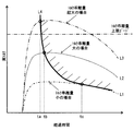
- FIG. 14 is an aspect showing how torque abnormality can be detected rapidly as described above, and the horizontal axis of FIG. 14 shows the elapsed time, and the vertical axis shows the actual output of the internal combustion engine (actual torque ) Shows how it rises.
- the dashed-dotted line L1 in the figure is an example in the case where the increase of the actual torque due to the abnormality is small and the torque deviation amount is small. In this case, the integrated value increases to the abnormality determination threshold at time tc and the abnormality is determined Be done.
- the dotted line L2 in the figure is an example in the case where the increase of the actual torque due to the abnormality is large and the amount of torque deviation is large.
- the integrated value rises to the abnormality determination threshold at time tb earlier than time tc, and abnormality determination is made.
- the two-dot chain line L3 in the figure is an example in the case where the increase in the actual torque due to the abnormality is even larger, and the torque deviation amount is larger than the upper limit guard value.
- the count value is limited to the upper limit guard value
- the integrated value increases to the abnormality determination threshold value at time ta that is earlier than time tb, and abnormality determination is performed.
- the solid line L4 in the figure indicates a required value for which the rapidity of the abnormality determination is required. As indicated by the solid line L4, as the increase speed of the actual torque is larger, it is required that the abnormality determination be made in a short time. However, since the magnitude of the count value is limited by the upper limit guard value, no abnormality determination is made in less than a predetermined time.
- the count value setting unit sets the count value so that the count value does not increase beyond the preset upper limit guard value. Therefore, when the phenomenon that the torque deviation amount exceeds the upper limit guard value increases instantaneously due to noise or the like, it is avoided that the integrated value instantaneously exceeds the abnormality determination value and the abnormality determination is made. . Therefore, it is possible to suppress that the torque abnormality determination is made even in the case where it is not necessary to cut the amount of torque deviation which instantaneously exceeds the upper limit guard value. In other words, the erroneous determination of the torque abnormality can be suppressed.
- the upper limit guard value is set to a smaller value, the erroneous determination suppression of the torque abnormality can be promoted, but as a tradeoff, the rapidity of the torque abnormality detection is impaired. And the optimal balance of misjudgment suppression and promptness differs according to the operating state of an internal combustion engine.
- the upper limit guard value is variably set according to the operating state of the internal combustion engine, the balance can be optimized. For example, the higher the engine speed and the higher the load operation, the smaller the sense of discomfort given to the vehicle driver due to the torque abnormality occurrence, the upper limit guard value is set to a smaller value, and torque abnormality detection Prioritize the promotion of false positives over promptness.
- the integration unit limits integration of the count value for the count value when the amount of torque deviation is within the range of the preset dead zone. Specifically, if the torque deviation amount is less than the upper value of the dead zone, the count value corresponding to the torque deviation amount is added to the integrated value while the count value corresponding to the upper value is subtracted from the integrated value. Therefore, when the phenomenon in which the torque deviation amount occurs with a small value in the range of the dead zone continues over a long period due to noise or the like, it is avoided that the integrated value exceeds the abnormal determination value and the abnormality determination is made. .
- the dead zone is variably set in accordance with the operating condition of the vehicle or the internal combustion engine, so that the balance can be optimized.
- the smaller the speed change ratio or the faster the traveling speed of the vehicle the smaller the sense of incongruity given to the vehicle driver along with the torque abnormality occurrence, and the dead zone is set in a wide range, and the torque abnormality detection is quicker Also give priority to promotion of misjudging suppression.
- the abnormality determination threshold value is set to a larger value, the erroneous determination suppression of the torque abnormality can be promoted, but as a tradeoff, the rapidity of the torque abnormality detection is impaired.
- the optimal balance between the erroneous determination suppression and the promptness differs depending on the operating condition of the vehicle and the operating condition of the internal combustion engine.
- the abnormality determination threshold value is variably set according to the driving state of the vehicle or the driving state of the internal combustion engine, the balance can be optimized.
- the ECU 10 (torque monitoring device) according to the present embodiment includes a control module 20 (control arithmetic device) and a monitoring module 30 (monitoring arithmetic device).
- the control module 20 is an arithmetic device that performs calculation using the control storage area 20m, and calculates a target control amount that is a target value of a control amount for controlling the combustion state of the internal combustion engine according to a user request torque.
- the monitoring module 30 is an arithmetic device that performs calculation using the monitoring storage area 30m different from the control storage area 20m, and includes a count value setting unit, an integration unit, and an abnormality determination unit.
- the monitoring module 30, which is a computing device that monitors torque, performs computation using the monitoring storage area 30m different from the control storage area 20m. Therefore, as illustrated in FIG. 13, the estimated torque for monitoring becomes an abnormal value while the required torque for monitoring does not occur at an abnormal time, so the amount of torque deviation increases and is stored in the control storage area 20 m. It is possible to monitor torque abnormalities caused by abnormal data.
- the calculation speed and calculation accuracy of the estimated torque and required torque used for monitoring are lower than the estimated torque and required torque used for control.
- the operation cycle of the monitoring module 30 is longer than the operation cycle of the control module 20. Therefore, it can be avoided that the operation processing load of the monitoring module 30 becomes larger than necessary.
- the monitoring module 30 includes the input securing unit 31 that checks that the data acquired from the outside of the monitoring module 30 is normal. Therefore, it is possible to improve the guarantee that the data used for the calculation of the monitoring module 30 is normal, and it is possible to meet the above request.
- the monitoring module 30 includes the engine required torque calculation unit 32 and the estimated torque calculation unit 33. Then, the engine required torque calculation unit 32 calculates, as reserve torque, a decrease in actual torque that occurs with the retardation of the ignition timing of the internal combustion engine, and calculates the engine required torque based on the calculated reserve torque and the user required torque. Therefore, the difference between the engine required torque and the estimated torque, which is caused due to the calculation of the engine required torque without considering the reserve torque, can be suppressed, so that the possibility of erroneous determination of torque abnormality can be suppressed.
- control module 20 sets the target ignition timing to be retarded at the time of catalyst warmup request, and the engine required torque calculation unit 32 performs combustion corresponding to the retarded amount of catalyst warmup request.
- the reserve torque is calculated to be equal to or more than the torque for the efficiency deterioration.
- control module 20 sets the target ignition timing to be retarded during idle operation, and the engine required torque calculation unit 32 reduces the combustion efficiency corresponding to the retarded amount of the idle required torque.
- the reserve torque is calculated to be equal to or higher than As described above, since the deterioration of the combustion efficiency caused by the retardation of the ignition timing such as the catalyst warm-up request and the idle request is reflected in the engine request torque for monitoring, the possibility of the above-mentioned erroneous determination can be suppressed.
- the disclosure in this specification is not limited to the illustrated embodiments.
- the disclosure includes the illustrated embodiments and variations based on them by those skilled in the art.
- the disclosure is not limited to the combination of parts and / or elements shown in the embodiments.
- the disclosure can be implemented in various combinations.
- the disclosure can have additional parts that can be added to the embodiments.
- the disclosure includes those in which parts and / or elements of the embodiments have been omitted.
- the disclosure includes replacements or combinations of parts and / or elements between one embodiment and another embodiment.
- the disclosed technical scope is not limited to the description of the embodiments. It is to be understood that the technical scopes disclosed herein are indicated by the description of the scope of the claims, and further include all modifications within the meaning and scope equivalent to the descriptions of the scope of the claims.
- the torque deviation amount when the torque deviation amount is less than the upper value of the dead zone, only the count value corresponding to the torque deviation amount is added to the integrated value, and the count value corresponding to the upper value is subtracted from the integrated value. , Integrated value will decrease.
- the torque deviation amount when the torque deviation amount is less than the upper value of the dead zone, the addition of the count value to the integrated value is prohibited, and the subtraction of the count value corresponding to the upper value from the integrated value is eliminated. May not decrease.
- the integration of the count value is limited in accordance with whether or not the torque deviation amount is within the range of the dead zone.
- the integration of the count value may be limited depending on whether or not the count value corresponding to the torque deviation amount is within the range of the dead zone.
- the upper limit guard value is variably set according to the operating state of the internal combustion engine. However, regardless of the operating state, the upper limit guard value may be set to a preset fixed value.
- the dead zone is variably set in accordance with the operating condition of the vehicle or the internal combustion engine, but the dead zone may be set to a preset fixed value regardless of the operating condition.
- the variable setting may be abolished and set to a preset fixed value.
- the torque abnormality determination process after S43 is executed on condition that the engine speed is equal to or more than a predetermined value.
- the torque abnormality determination processing after S43 may be executed.
- the monitoring module 30 includes a count value setting unit, an integration unit, and an abnormality determination unit, and setting of the count value, calculation of the integration value, and abnormality determination are performed by the monitoring module 30.
- the control module 20 may include a count value setting unit, an integration unit, and an abnormality determination unit, and setting of the count value, calculation of the integration value, and abnormality determination may be performed by the control module 20. Also, it may be executed by both the control module 20 and the monitoring module 30.
- the calculation speed of the monitoring module 30 is slower than the calculation speed of the control module 20. Specifically, the check processing speed by the input securing unit 31 becomes a bottleneck, and the calculation speed of the engine required torque calculation unit 32 and the estimated torque calculation unit 33 is slower than the calculation speed of the engine required torque calculation unit 21 . On the other hand, the calculation speed of the monitoring module 30 may be equal to the calculation speed of the control module 20.
- control storage area 20m and the monitoring storage area 30m are set in the storage area of one common memory 11m.
- a plurality of memories may be provided in the ECU 10, the storage area of the first memory may be set as the control storage area, and the storage area of the second memory may be set as the monitoring storage area.
- one common MCU 11 has the control storage area 20m and the monitoring storage area 30m.
- the ECU 10 may be provided with a plurality of MCUs, the first MCU may have a control storage area, and the second MCU may have a monitoring storage area.
- the internal combustion engine mounted on the vehicle is the control target of the ECU 10, but a stationary internal combustion engine other than the on-vehicle may be the control target of the ECU 10.
- a vehicle drive motor mounted on a hybrid vehicle or an electric vehicle may be monitored. In that case, the count value is set to a larger value as the amount of deviation between the required torque of the vehicle drive motor and the actual torque is larger.
Landscapes
- Engineering & Computer Science (AREA)
- Chemical & Material Sciences (AREA)
- Combustion & Propulsion (AREA)
- Mechanical Engineering (AREA)
- General Engineering & Computer Science (AREA)
- Combined Controls Of Internal Combustion Engines (AREA)
- Control Of Vehicle Engines Or Engines For Specific Uses (AREA)
Priority Applications (2)
| Application Number | Priority Date | Filing Date | Title |
|---|---|---|---|
| DE112018003932.3T DE112018003932T5 (de) | 2017-08-01 | 2018-07-06 | Drehmomentüberwachungsvorrichtung und steuerungssystem für verbrennungsmotoren |
| US16/775,651 US11313306B2 (en) | 2017-08-01 | 2020-01-29 | Torque monitoring device |
Applications Claiming Priority (2)
| Application Number | Priority Date | Filing Date | Title |
|---|---|---|---|
| JP2017-149368 | 2017-08-01 | ||
| JP2017149368A JP6809408B2 (ja) | 2017-08-01 | 2017-08-01 | トルク監視装置および内燃機関制御システム |
Related Child Applications (1)
| Application Number | Title | Priority Date | Filing Date |
|---|---|---|---|
| US16/775,651 Continuation US11313306B2 (en) | 2017-08-01 | 2020-01-29 | Torque monitoring device |
Publications (1)
| Publication Number | Publication Date |
|---|---|
| WO2019026545A1 true WO2019026545A1 (ja) | 2019-02-07 |
Family
ID=65232756
Family Applications (1)
| Application Number | Title | Priority Date | Filing Date |
|---|---|---|---|
| PCT/JP2018/025697 Ceased WO2019026545A1 (ja) | 2017-08-01 | 2018-07-06 | トルク監視装置および内燃機関制御システム |
Country Status (4)
| Country | Link |
|---|---|
| US (1) | US11313306B2 (enExample) |
| JP (1) | JP6809408B2 (enExample) |
| DE (1) | DE112018003932T5 (enExample) |
| WO (1) | WO2019026545A1 (enExample) |
Cited By (4)
| Publication number | Priority date | Publication date | Assignee | Title |
|---|---|---|---|---|
| US10907555B2 (en) | 2017-07-28 | 2021-02-02 | Denso Corporation | Internal combustion engine control system |
| US11008961B2 (en) | 2017-07-28 | 2021-05-18 | Denso Corporation | Internal combustion engine control system |
| US11028793B2 (en) | 2017-08-30 | 2021-06-08 | Denso Corporation | Internal combustion engine control system |
| CN113374591A (zh) * | 2020-02-25 | 2021-09-10 | 本田技研工业株式会社 | 发动机控制装置 |
Families Citing this family (6)
| Publication number | Priority date | Publication date | Assignee | Title |
|---|---|---|---|---|
| GB2571306A (en) * | 2018-02-23 | 2019-08-28 | Sony Interactive Entertainment Europe Ltd | Video recording and playback systems and methods |
| JP6939718B2 (ja) * | 2018-06-26 | 2021-09-22 | 日本電信電話株式会社 | ネットワーク機器及びネットワーク機器の設定方法 |
| WO2020121807A1 (ja) * | 2018-12-14 | 2020-06-18 | 日立オートモティブシステムズ株式会社 | 制御装置 |
| JP6758451B1 (ja) * | 2019-04-17 | 2020-09-23 | 三菱電機株式会社 | 内燃機関の制御装置 |
| GB2584427B (en) * | 2019-05-29 | 2021-11-10 | Jaguar Land Rover Ltd | Controller for a vehicle internal combustion engine |
| CN115800841A (zh) * | 2022-11-17 | 2023-03-14 | 中国第一汽车股份有限公司 | 一种汽油机发电机控制及扭矩补偿方法 |
Citations (6)
| Publication number | Priority date | Publication date | Assignee | Title |
|---|---|---|---|---|
| JP2001152882A (ja) * | 1999-11-25 | 2001-06-05 | Denso Corp | 内燃機関の電磁駆動バルブの異常診断装置 |
| JP2007303294A (ja) * | 2006-05-09 | 2007-11-22 | Denso Corp | 過給機付き内燃機関の制御装置 |
| JP2014073768A (ja) * | 2012-10-04 | 2014-04-24 | Mitsubishi Motors Corp | ハイブリッド電気車両の協調制御装置排気浄化装置 |
| JP2014080951A (ja) * | 2012-10-18 | 2014-05-08 | Denso Corp | 車両用制御装置 |
| JP2015010498A (ja) * | 2013-06-27 | 2015-01-19 | 株式会社デンソー | 燃料噴射制御装置 |
| WO2015072269A1 (ja) * | 2013-11-13 | 2015-05-21 | 本田技研工業株式会社 | 原動機の駆動制御装置 |
Family Cites Families (15)
| Publication number | Priority date | Publication date | Assignee | Title |
|---|---|---|---|---|
| JPH04203250A (ja) * | 1990-11-29 | 1992-07-23 | Mitsubishi Motors Corp | 走行負荷分補償式速度制御部付ドライブバイワイヤ式車両 |
| DE19609242A1 (de) * | 1996-03-09 | 1997-09-11 | Bosch Gmbh Robert | Verfahren und Vorrichtung zur Steuerung einer Antriebseinheit eines Fahrzeugs |
| JPH10213469A (ja) * | 1997-01-30 | 1998-08-11 | Ricoh Co Ltd | 感熱式フローセンサの特性補償方法 |
| DE19808167C1 (de) * | 1998-02-27 | 1999-08-26 | Daimler Chrysler Ag | Verfahren zur Korrektur eines rechnerisch ermittelten Drehmoments im Antriebsstrang eines Kraftfahrzeugs |
| DE19836059A1 (de) * | 1998-08-10 | 2000-02-17 | Mannesmann Vdo Ag | Verfahren und Vorrichtung zur Ansteuerung einer Leistungsverstelleinrichtung eines Fahrzeugmotors |
| JP2001295677A (ja) * | 2000-03-29 | 2001-10-26 | Robert Bosch Gmbh | 車両速度の制御方法および装置 |
| JP2001296155A (ja) * | 2000-04-12 | 2001-10-26 | Yazaki Corp | 電子式積算流量計 |
| JP3855677B2 (ja) | 2001-04-27 | 2006-12-13 | 株式会社デンソー | 電子制御システムの故障診断装置 |
| DE10210684B4 (de) * | 2002-03-12 | 2005-04-14 | Robert Bosch Gmbh | Verfahren und Vorrichtung zur Überwachung eines Moments einer Antriebseinheit eines Fahrzeugs |
| JP2007224728A (ja) * | 2006-02-21 | 2007-09-06 | Denso Corp | エンジンオイル供給制御装置 |
| JP2013015444A (ja) * | 2011-07-05 | 2013-01-24 | Akebono Brake Ind Co Ltd | 信号処理装置、信号処理方法、及び信号処理プログラム |
| JP6248548B2 (ja) * | 2013-10-31 | 2017-12-20 | 株式会社デンソー | 車両制御装置 |
| JP2017149368A (ja) | 2016-02-26 | 2017-08-31 | 株式会社東芝 | 情報処理装置及び情報処理の方法 |
| JP6780600B2 (ja) | 2017-07-28 | 2020-11-04 | 株式会社デンソー | 内燃機関制御システム |
| JP6717271B2 (ja) | 2017-07-28 | 2020-07-01 | 株式会社デンソー | 内燃機関制御システム |
-
2017
- 2017-08-01 JP JP2017149368A patent/JP6809408B2/ja active Active
-
2018
- 2018-07-06 WO PCT/JP2018/025697 patent/WO2019026545A1/ja not_active Ceased
- 2018-07-06 DE DE112018003932.3T patent/DE112018003932T5/de active Pending
-
2020
- 2020-01-29 US US16/775,651 patent/US11313306B2/en active Active
Patent Citations (6)
| Publication number | Priority date | Publication date | Assignee | Title |
|---|---|---|---|---|
| JP2001152882A (ja) * | 1999-11-25 | 2001-06-05 | Denso Corp | 内燃機関の電磁駆動バルブの異常診断装置 |
| JP2007303294A (ja) * | 2006-05-09 | 2007-11-22 | Denso Corp | 過給機付き内燃機関の制御装置 |
| JP2014073768A (ja) * | 2012-10-04 | 2014-04-24 | Mitsubishi Motors Corp | ハイブリッド電気車両の協調制御装置排気浄化装置 |
| JP2014080951A (ja) * | 2012-10-18 | 2014-05-08 | Denso Corp | 車両用制御装置 |
| JP2015010498A (ja) * | 2013-06-27 | 2015-01-19 | 株式会社デンソー | 燃料噴射制御装置 |
| WO2015072269A1 (ja) * | 2013-11-13 | 2015-05-21 | 本田技研工業株式会社 | 原動機の駆動制御装置 |
Cited By (5)
| Publication number | Priority date | Publication date | Assignee | Title |
|---|---|---|---|---|
| US10907555B2 (en) | 2017-07-28 | 2021-02-02 | Denso Corporation | Internal combustion engine control system |
| US11008961B2 (en) | 2017-07-28 | 2021-05-18 | Denso Corporation | Internal combustion engine control system |
| US11028793B2 (en) | 2017-08-30 | 2021-06-08 | Denso Corporation | Internal combustion engine control system |
| CN113374591A (zh) * | 2020-02-25 | 2021-09-10 | 本田技研工业株式会社 | 发动机控制装置 |
| CN113374591B (zh) * | 2020-02-25 | 2023-03-07 | 本田技研工业株式会社 | 发动机控制装置 |
Also Published As
| Publication number | Publication date |
|---|---|
| US11313306B2 (en) | 2022-04-26 |
| JP6809408B2 (ja) | 2021-01-06 |
| DE112018003932T5 (de) | 2020-04-30 |
| JP2019027394A (ja) | 2019-02-21 |
| US20200165996A1 (en) | 2020-05-28 |
Similar Documents
| Publication | Publication Date | Title |
|---|---|---|
| WO2019026545A1 (ja) | トルク監視装置および内燃機関制御システム | |
| JP6717271B2 (ja) | 内燃機関制御システム | |
| US10696293B2 (en) | Start controller and start controlling method | |
| JP6780600B2 (ja) | 内燃機関制御システム | |
| JP5158228B2 (ja) | 内燃機関制御装置 | |
| JP6809415B2 (ja) | 内燃機関制御システム | |
| JP2011127439A (ja) | 内燃機関の制御装置 | |
| US11118527B2 (en) | Internal combustion engine control system | |
| JP7067078B2 (ja) | 内燃機関制御システム | |
| JP2017007457A (ja) | ハイブリッド車両 | |
| JP7505298B2 (ja) | 車両の制御装置 | |
| JP2019094873A (ja) | 内燃機関制御システム | |
| CN113374591A (zh) | 发动机控制装置 | |
| JP2018080581A (ja) | エンジン停止位置制御装置 | |
| JP5868075B2 (ja) | 発電機の制御装置 | |
| JP2017001568A (ja) | ハイブリッド車両 | |
| JP2007046573A (ja) | 内燃機関の制御装置 | |
| JP2019019712A (ja) | 内燃機関の制御装置 |
Legal Events
| Date | Code | Title | Description |
|---|---|---|---|
| 121 | Ep: the epo has been informed by wipo that ep was designated in this application |
Ref document number: 18840225 Country of ref document: EP Kind code of ref document: A1 |
|
| 122 | Ep: pct application non-entry in european phase |
Ref document number: 18840225 Country of ref document: EP Kind code of ref document: A1 |