WO2019021918A1 - バルブ装置、および、冷却システム - Google Patents
バルブ装置、および、冷却システム Download PDFInfo
- Publication number
- WO2019021918A1 WO2019021918A1 PCT/JP2018/027006 JP2018027006W WO2019021918A1 WO 2019021918 A1 WO2019021918 A1 WO 2019021918A1 JP 2018027006 W JP2018027006 W JP 2018027006W WO 2019021918 A1 WO2019021918 A1 WO 2019021918A1
- Authority
- WO
- WIPO (PCT)
- Prior art keywords
- engine
- housing
- valve
- valve body
- cooling water
- Prior art date
- Legal status (The legal status is an assumption and is not a legal conclusion. Google has not performed a legal analysis and makes no representation as to the accuracy of the status listed.)
- Ceased
Links
Images


Classifications
-
- F—MECHANICAL ENGINEERING; LIGHTING; HEATING; WEAPONS; BLASTING
- F01—MACHINES OR ENGINES IN GENERAL; ENGINE PLANTS IN GENERAL; STEAM ENGINES
- F01P—COOLING OF MACHINES OR ENGINES IN GENERAL; COOLING OF INTERNAL-COMBUSTION ENGINES
- F01P7/00—Controlling of coolant flow
- F01P7/14—Controlling of coolant flow the coolant being liquid
- F01P7/16—Controlling of coolant flow the coolant being liquid by thermostatic control
- F01P7/165—Controlling of coolant flow the coolant being liquid by thermostatic control characterised by systems with two or more loops
-
- F—MECHANICAL ENGINEERING; LIGHTING; HEATING; WEAPONS; BLASTING
- F01—MACHINES OR ENGINES IN GENERAL; ENGINE PLANTS IN GENERAL; STEAM ENGINES
- F01P—COOLING OF MACHINES OR ENGINES IN GENERAL; COOLING OF INTERNAL-COMBUSTION ENGINES
- F01P3/00—Liquid cooling
- F01P3/02—Arrangements for cooling cylinders or cylinder heads
-
- F—MECHANICAL ENGINEERING; LIGHTING; HEATING; WEAPONS; BLASTING
- F16—ENGINEERING ELEMENTS AND UNITS; GENERAL MEASURES FOR PRODUCING AND MAINTAINING EFFECTIVE FUNCTIONING OF MACHINES OR INSTALLATIONS; THERMAL INSULATION IN GENERAL
- F16K—VALVES; TAPS; COCKS; ACTUATING-FLOATS; DEVICES FOR VENTING OR AERATING
- F16K11/00—Multiple-way valves, e.g. mixing valves; Pipe fittings incorporating such valves
- F16K11/02—Multiple-way valves, e.g. mixing valves; Pipe fittings incorporating such valves with all movable sealing faces moving as one unit
- F16K11/06—Multiple-way valves, e.g. mixing valves; Pipe fittings incorporating such valves with all movable sealing faces moving as one unit comprising only sliding valves, i.e. sliding closure elements
- F16K11/072—Multiple-way valves, e.g. mixing valves; Pipe fittings incorporating such valves with all movable sealing faces moving as one unit comprising only sliding valves, i.e. sliding closure elements with pivoted closure members
-
- F—MECHANICAL ENGINEERING; LIGHTING; HEATING; WEAPONS; BLASTING
- F16—ENGINEERING ELEMENTS AND UNITS; GENERAL MEASURES FOR PRODUCING AND MAINTAINING EFFECTIVE FUNCTIONING OF MACHINES OR INSTALLATIONS; THERMAL INSULATION IN GENERAL
- F16K—VALVES; TAPS; COCKS; ACTUATING-FLOATS; DEVICES FOR VENTING OR AERATING
- F16K27/00—Construction of housing; Use of materials therefor
-
- B—PERFORMING OPERATIONS; TRANSPORTING
- B60—VEHICLES IN GENERAL
- B60K—ARRANGEMENT OR MOUNTING OF PROPULSION UNITS OR OF TRANSMISSIONS IN VEHICLES; ARRANGEMENT OR MOUNTING OF PLURAL DIVERSE PRIME-MOVERS IN VEHICLES; AUXILIARY DRIVES FOR VEHICLES; INSTRUMENTATION OR DASHBOARDS FOR VEHICLES; ARRANGEMENTS IN CONNECTION WITH COOLING, AIR INTAKE, GAS EXHAUST OR FUEL SUPPLY OF PROPULSION UNITS IN VEHICLES
- B60K11/00—Arrangement in connection with cooling of propulsion units
- B60K11/02—Arrangement in connection with cooling of propulsion units with liquid cooling
- B60K11/04—Arrangement or mounting of radiators, radiator shutters, or radiator blinds
-
- B—PERFORMING OPERATIONS; TRANSPORTING
- B60—VEHICLES IN GENERAL
- B60K—ARRANGEMENT OR MOUNTING OF PROPULSION UNITS OR OF TRANSMISSIONS IN VEHICLES; ARRANGEMENT OR MOUNTING OF PLURAL DIVERSE PRIME-MOVERS IN VEHICLES; AUXILIARY DRIVES FOR VEHICLES; INSTRUMENTATION OR DASHBOARDS FOR VEHICLES; ARRANGEMENTS IN CONNECTION WITH COOLING, AIR INTAKE, GAS EXHAUST OR FUEL SUPPLY OF PROPULSION UNITS IN VEHICLES
- B60K6/00—Arrangement or mounting of plural diverse prime-movers for mutual or common propulsion, e.g. hybrid propulsion systems comprising electric motors and internal combustion engines
- B60K6/20—Arrangement or mounting of plural diverse prime-movers for mutual or common propulsion, e.g. hybrid propulsion systems comprising electric motors and internal combustion engines the prime-movers consisting of electric motors and internal combustion engines, e.g. HEVs
- B60K6/22—Arrangement or mounting of plural diverse prime-movers for mutual or common propulsion, e.g. hybrid propulsion systems comprising electric motors and internal combustion engines the prime-movers consisting of electric motors and internal combustion engines, e.g. HEVs characterised by apparatus, components or means specially adapted for HEVs
- B60K6/24—Arrangement or mounting of plural diverse prime-movers for mutual or common propulsion, e.g. hybrid propulsion systems comprising electric motors and internal combustion engines the prime-movers consisting of electric motors and internal combustion engines, e.g. HEVs characterised by apparatus, components or means specially adapted for HEVs characterised by the combustion engines
-
- B—PERFORMING OPERATIONS; TRANSPORTING
- B60—VEHICLES IN GENERAL
- B60Y—INDEXING SCHEME RELATING TO ASPECTS CROSS-CUTTING VEHICLE TECHNOLOGY
- B60Y2200/00—Type of vehicle
- B60Y2200/90—Vehicles comprising electric prime movers
- B60Y2200/92—Hybrid vehicles
-
- F—MECHANICAL ENGINEERING; LIGHTING; HEATING; WEAPONS; BLASTING
- F01—MACHINES OR ENGINES IN GENERAL; ENGINE PLANTS IN GENERAL; STEAM ENGINES
- F01P—COOLING OF MACHINES OR ENGINES IN GENERAL; COOLING OF INTERNAL-COMBUSTION ENGINES
- F01P3/00—Liquid cooling
- F01P3/02—Arrangements for cooling cylinders or cylinder heads
- F01P2003/021—Cooling cylinders
-
- F—MECHANICAL ENGINEERING; LIGHTING; HEATING; WEAPONS; BLASTING
- F01—MACHINES OR ENGINES IN GENERAL; ENGINE PLANTS IN GENERAL; STEAM ENGINES
- F01P—COOLING OF MACHINES OR ENGINES IN GENERAL; COOLING OF INTERNAL-COMBUSTION ENGINES
- F01P7/00—Controlling of coolant flow
- F01P7/14—Controlling of coolant flow the coolant being liquid
- F01P2007/146—Controlling of coolant flow the coolant being liquid using valves
-
- F—MECHANICAL ENGINEERING; LIGHTING; HEATING; WEAPONS; BLASTING
- F01—MACHINES OR ENGINES IN GENERAL; ENGINE PLANTS IN GENERAL; STEAM ENGINES
- F01P—COOLING OF MACHINES OR ENGINES IN GENERAL; COOLING OF INTERNAL-COMBUSTION ENGINES
- F01P2050/00—Applications
- F01P2050/24—Hybrid vehicles
-
- F—MECHANICAL ENGINEERING; LIGHTING; HEATING; WEAPONS; BLASTING
- F01—MACHINES OR ENGINES IN GENERAL; ENGINE PLANTS IN GENERAL; STEAM ENGINES
- F01P—COOLING OF MACHINES OR ENGINES IN GENERAL; COOLING OF INTERNAL-COMBUSTION ENGINES
- F01P2060/00—Cooling circuits using auxiliaries
- F01P2060/04—Lubricant cooler
- F01P2060/045—Lubricant cooler for transmissions
-
- F—MECHANICAL ENGINEERING; LIGHTING; HEATING; WEAPONS; BLASTING
- F01—MACHINES OR ENGINES IN GENERAL; ENGINE PLANTS IN GENERAL; STEAM ENGINES
- F01P—COOLING OF MACHINES OR ENGINES IN GENERAL; COOLING OF INTERNAL-COMBUSTION ENGINES
- F01P2060/00—Cooling circuits using auxiliaries
- F01P2060/08—Cabin heater
-
- F—MECHANICAL ENGINEERING; LIGHTING; HEATING; WEAPONS; BLASTING
- F01—MACHINES OR ENGINES IN GENERAL; ENGINE PLANTS IN GENERAL; STEAM ENGINES
- F01P—COOLING OF MACHINES OR ENGINES IN GENERAL; COOLING OF INTERNAL-COMBUSTION ENGINES
- F01P2060/00—Cooling circuits using auxiliaries
- F01P2060/12—Turbo charger
-
- F—MECHANICAL ENGINEERING; LIGHTING; HEATING; WEAPONS; BLASTING
- F01—MACHINES OR ENGINES IN GENERAL; ENGINE PLANTS IN GENERAL; STEAM ENGINES
- F01P—COOLING OF MACHINES OR ENGINES IN GENERAL; COOLING OF INTERNAL-COMBUSTION ENGINES
- F01P2060/00—Cooling circuits using auxiliaries
- F01P2060/16—Outlet manifold
Definitions
- the present disclosure relates to a valve device and a cooling system including the same.
- a valve device that includes a housing and a valve body, and communicates a port of the housing with the inside of the housing according to the rotational position of the valve body.
- the housing has a plurality of ports
- the valve body has a plurality of openings. The openings are formed at axially different positions with respect to the other openings, and can communicate with any one of the plurality of ports.
- the valve body changes the degree of communication between the opening and the port in accordance with the rotational position.
- valve device is installed in the engine room of the vehicle together with the engine.
- a transmission, an intake manifold, an exhaust manifold, and the like, for example, an air cleaner, a battery, and the like are installed around the engine.
- a power conversion device or the like that adjusts the current flowing from the battery to the motor for driving the vehicle may be installed around the engine.
- Patent Document 1 does not disclose how to arrange the valve device in a narrow space.
- An object of the present disclosure is to provide a valve device that can be installed in a narrow space.
- Another object of the present invention is to provide a cooling system provided with the valve device.
- the valve device of the present disclosure controls the flow rate of the engine coolant, and includes a housing and a valve body.
- the housing has a plurality of ports.
- the valve body is rotatably provided around the axial center in the housing, and has a plurality of openings formed at mutually different positions in the axial direction and capable of communicating with any one of the plurality of ports. The degree of communication between the opening and the port is changed according to the rotational position.
- the valve device is installed such that the axial direction of the valve body is substantially orthogonal to the axial direction of the drive shaft of the engine.
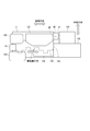
- FIG. 1 is a schematic view illustrating a cooling system to which a cooling water control valve according to a first embodiment is applied
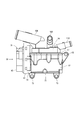
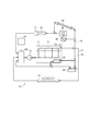
- 2 is an external view of the cooling water control valve of FIG. 1
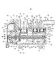
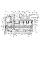
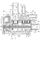
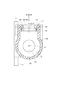
- 3 is a cross-sectional view showing the cooling water control valve of FIG. 2 in a longitudinal cross section along the axial center of the valve body, in which the communication degree of the opening of the valve body is 0%
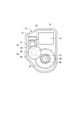
- FIG. 4 is a view when the cover of the drive unit of the coolant control valve of FIG. 2 is removed from the case as viewed from the IV direction
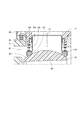
- 5 is an enlarged view of a portion V of FIG.
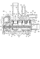
- FIG. 3 is a cross-sectional view showing the cooling water control valve of FIG. 2 in a longitudinal cross section along the axial center of the valve body, in which the communication degree of the opening of the valve body is 100%, 7 is a cross-sectional view taken along line VII-VII of the housing and the holding plate of FIG. 3;
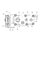
- FIG. 8 is a view of the cooling water control valve of FIG. 3 when a pipe member is removed as viewed from the direction VIII,
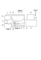
- FIG. 9 is a schematic view of the engine and peripherals of FIG. 1 as viewed from the front of the vehicle, 10 is a view of the coolant control valve, the engine, the power converter and the transmission of FIG. 9 as viewed from the X direction, FIG.
- FIG. 11 is a schematic view illustrating an engine and peripheral devices to which the cooling water control valve according to the second embodiment is applied, corresponding to FIG. 9 in the first embodiment
- FIG. 12 is a schematic view illustrating a cooling system to which a cooling water control valve according to a third embodiment is applied, and is a view corresponding to FIG. 1 in the first embodiment
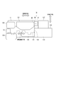
- FIG. 13 is a cross-sectional view of the cooling water control valve of FIG. 12, in which the degree of communication of the opening of the valve body is 0%
- FIG. 14 is a cross-sectional view of a state in which the valve body has been rotated until the degree of communication of the opening reaches 100% from the state of FIG. 13
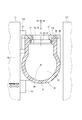
- 15 is a cross-sectional view of the housing and the holding plate of FIG.
- FIG. 13 taken along line XV-XV; 16 is a schematic view of the engine and peripherals of FIG. 12 as viewed from the front of the vehicle, FIG. 17 is a schematic view of an engine and peripheral devices to which the cooling water control valve according to the fourth embodiment is applied, viewed from the front side of the vehicle.
- First Embodiment A coolant control valve as a valve device according to a first embodiment is shown in FIG.
- the coolant control valve 10 is applied to a cooling system 12 including an engine 11 for a vehicle.
- the cooling system 12 includes an engine 11, a water pump 13, a cooling water control valve 10, a radiator 14, a water temperature sensor 15, an electronic control unit 16, and the like.
- the water pump 13 is provided at a place where a plurality of circulation paths 17, 18, 19 are gathered, and pumps cooling water as a cooling medium toward the water jacket 21 of the engine 11.
- the cooling water control valve 10 is a branch point of the circulation paths 17, 18 and 19, and is provided, for example, at the outlet of the water jacket 21, and adjusts the flow rate of the cooling water flowing through the circulation paths 17, 18 and 19. .
- the radiator 14 is a heat exchanger provided in the middle of the circulation path 17 and performs heat exchange between the cooling water and the air to lower the temperature of the cooling water.
- An engine oil cooler 22 and a transmission oil cooler 23 are provided in the middle of the circulation path 18.
- a heater core 24, a throttle valve 25, a supercharger 26, an EGR valve 27 and an EGR cooler 28 are provided in the middle of the circulation path 19.
- the water temperature sensor 15 is provided in front of the cooling water control valve 10.
- the electronic control unit 16 operates the cooling water control valve 10 in accordance with the water temperature detected by the water temperature sensor 15 to control the flow rate of the cooling water in the circulation paths 17, 18, 19.
- the coolant control valve 10 includes a drive unit 31, a housing 32, a valve body 33, seal units 34, 35 and 36, a holding plate 37, and a pipe member 38.
- the drive unit 31 includes a cover 43 forming a housing space between the case 41 and the case 41, and a motor 44 and a reduction gear 45 provided in the housing space. , And a rotation angle sensor 46.
- the case 41 has a plate-like base portion 47 and a connection fitting portion 42 fitted to the connection opening 74 of the housing 32.
- a shaft insertion hole 48 and a bearing 49 are provided at a central portion of the connection fitting portion 42.
- One end portion of a shaft portion 81 of the valve body 33 is inserted into the shaft insertion hole 48, and the bearing 49 supports one end portion of the shaft portion 81.
- the reduction gear 45 includes a cylindrical gear 51, a first gear 52, a second gear 53, and a third gear 54.
- the cylindrical gear 51 is fixed to the output shaft 55 of the motor 44.
- the first gear 52 has a first large diameter gear portion 56 meshing with the cylindrical gear 51 and a first small diameter gear portion 57 having a smaller diameter than that.
- the second gear 53 has a second large diameter gear portion 58 meshing with the first small diameter gear portion 57 and a second small diameter gear portion 59 having a smaller diameter than that.
- the third gear 54 meshes with the second small diameter gear portion 59 and is fixed to one end of the shaft portion 81 of the valve body 33.
- the reduction gear 45 reduces the rotational speed of the power of the motor 44 and outputs it.
- the rotation angle sensor 46 includes magnets 61 and 62 provided in the third gear 54, and a magnetic detection unit 63 provided between the magnets 61 and 62 and on the axial center AX of the valve body 33, have.
- the magnetic detection unit 63 includes, for example, a Hall IC, and detects the rotation angle of the valve 33 by detecting a magnetic field that changes with the rotation of the valve 33.
- the housing 32 has a cylindrical housing main body 71 having an internal space 75, a fixing flange 73 for fixing to the engine 11, and a mounting for mounting the drive part 31. And a flange 72.
- a connection opening 74 is formed at one end of the housing body 71.
- the housing body 71 has an input port 76 and a plurality of output ports 77, 78, 79, which connect the internal space 75 with the outside (i.e., outside of the housing 32).
- the input port 76 and the output ports 77, 78, 79 are formed to radially penetrate the side portion of the housing main body 71, that is, the cylindrical portion.
- the valve body 33 is rotatably provided around the axis AX in the internal space 75, and communicates or blocks the input port 76 and the output ports 77, 78, 79, depending on the rotational position.
- the valve body 33 has a shaft portion 81 and a cylindrical portion 82 provided outside the shaft portion 81.
- the shaft 81 is rotatably supported by the bearing 49 and the end of the housing body 71.
- the cylindrical portion 82 is connected to the shaft portion 81 at one end in the axial direction.
- the shaft portion 81 and the cylindrical portion 82 are made of one member.
- a flow path 83 in the valve body is formed between the cylindrical portion 82 and the shaft portion 81.
- the cylindrical portion 82 has openings 87, 88, 89 for connecting any one of the output ports 77, 78, 79 and the in-valve internal flow path 83 according to the rotational position of the valve body 33, and the rotational position of the valve body 33. Regardless, it has the opening 92 which connects the input port 76 and the in-valve internal flow path 83 via the outer side of the valve body 33 (hereinafter, the valve body outer space 91) in the internal space 75.
- the openings 87, 88, 89 are formed at mutually different positions in the axial direction and can communicate with any one of the plurality of output ports 77, 78, 79.
- the opening 87 is formed in the annular portion 84, and can connect the output port 77 and the internal flow passage 83.
- the opening 88 is formed in the annular portion 85, and can connect the output port 78 and the internal flow passage 83.
- the opening 89 is formed in the annular portion 86, and can connect the output port 79 and the internal flow passage 83.
- the opening 92 is formed between the annular portion 84 and the annular portion 85.
- the holding plate 37 is a holding member for holding the seal units 34, 35, 36, and has a plate portion 95 and holding portions 96, 97, 98.
- the plate portion 95 has a plate shape and is fixed to the housing main body portion 71.
- the holding portions 96, 97, 98 are annular protrusions which respectively project from the plate portion 95 into the output ports 77, 78, 79.
- the seal units 34, 35, 36 are provided corresponding to the output ports 77, 78, 79, respectively.
- the seal unit 34 includes a valve seal 101, a sleeve 102, a spring 103 and a seal member 104.
- the valve seal 101 is an annular seal member in contact with the outer wall surface of the annular portion 84 of the valve body 33.
- the sleeve 102 is a tubular member provided from the output port 77 to the valve body outer space 91, and holds the valve seal 101.
- the spring 103 biases the sleeve 102 toward the annular portion 84.
- the seal member 104 seals between the holding portion 96 of the holding plate 37 and the sleeve 102.
- the seal unit 34 seals between the output port 77 and the valve body outer space 91.
- the seal unit 35 has the same valve seal as the seal unit 34, a sleeve, a spring and a seal member, and seals between the output port 78 and the valve body outer space 91.
- the seal unit 36 has the same valve seal as the seal unit 34, a sleeve, a spring and a seal member, and seals between the output port 79 and the valve body outer space 91.
- the pipe member 38 includes a pipe 106 having a flow path 105 connected to the output port 77, a pipe 108 having a flow path 107 connected to the output port 78, and an output And a pipe 110 having a flow passage 109 connected to the port 79.
- the input port 76 is connected to the outlet of the water jacket 21.
- the pipe 106 is connected to the circulation path 17.
- the pipe 108 is connected to the circulation path 18.
- the pipe 110 is connected to the circulation path 19.
- the cooling water control valve 10 configured as described above, the cooling water whose temperature has risen by taking heat of the engine 11 when flowing through the water jacket 21 flows into the valve body outer space 91 through the input port 76.
- the cooling water in the valve body outer space 91 flows into the internal flow passage 83 through the opening 92 of the valve body 33.
- the cooling water of the valve internal flow passage 83 is distributed to the pipes 106, 108, 110 in accordance with the degree of communication of the openings 87, 88, 89 of the valve body 33 with the output ports 77, 78, 79.
- the degree of communication changes according to the rotational position of the valve body 33. That is, the valve body 33 changes the degree of communication between the openings 87, 88, 89 and the output ports 77, 78, 79 in accordance with the rotational position. For example, in FIG. 3, the degree of communication of each of the openings 87, 88, and 89 is 0%. On the other hand, in FIG. 6, the degree of communication of each of the openings 87, 88 and 89 is 100%.
- the coolant control valve 10 changes the degree of communication of the openings 87, 88, 89 between 0% and 100% by changing the rotational position of the valve body 33 from the state of FIG. 3 to the state of FIG. And control the flow rate of the cooling water in the circulation paths 17, 18, 19.
- the input port 76 is formed to pass through the side of the housing 32 attached to the engine 11, that is, the side provided with the fixing flange 73.
- the input port 76 is connected to the outlet of the water jacket 21 (see FIG. 1) by attaching the housing 32 to the engine 11. Therefore, piping for connecting the input port 76 to the water jacket 21 is not particularly required.
- At least a part of the output ports 77, 78, 79 overlap in the circumferential direction as viewed in the axial direction (direction parallel to the axis AX). That is, "at least a part of one output port overlaps with all other output ports when viewed in the axial direction".
- one output port is the output port 77 as an example
- at least a part of the output port 77 overlaps the output ports 78 and 79 when viewed in the axial direction.
- all the output ports 77, 78, 79 appear in the cross section including the axis AX as shown in FIG.
- the output ports 77, 78, 79 are provided on one side surface 115 of the housing 32. Further, as shown in FIG. 8, the output ports 77, 78, 79 are provided to be aligned in a straight line.
- the output ports 77, 78, 79 can be concentrated on a part of the housing 32 in the rotational direction of the valve body 33. Therefore, at least the root portion of the pipes 106, 108, 110 connected to the output ports 77, 78, 79 can be accommodated as much as possible within the width of the housing 32. Therefore, the cooling water control valve 10 can be thinned.
- the opening directions D1, D2, D3 of the output ports 77, 78, 79 are parallel to one another.
- One side surface 115 is a plane, and the opening directions D1, D2, and D3 are directions perpendicular to the one side surface 115.
- the holding plate 37 holds all the seal units 34, 35, 36 collectively. Therefore, the work efficiency can be improved by sub-assembling the seal units 34, 35, 36 and the holding plate 37 in advance and assembling it into the housing 32.
- the holding plate 37 is a separate member from the pipe member 38. As a result, even when the pipe member 38 is removed, the state where the seal units 34, 35, 36 are assembled to the housing 32 is maintained. Moreover, the cooling water control valve 10 of 1st Embodiment can unify the shape of the state which removed the pipe member 38 with respect to the other cooling water control valve which has a pipe member different from the pipe member 38. FIG. Therefore, the work of inspecting the leak of the seal units 34, 35, 36 becomes easy. For example, it is easy to automate the work of checking for leaks.
- the pipe member 38 is formed by integrally forming all the pipes 106, 108, 110. Therefore, all the pipes 106, 108, 110 can be assembled by one operation, and the working efficiency can be enhanced.
- the engine 11 is disposed such that the axial direction (hereinafter, drive shaft direction) of the crankshaft 131, which is the drive shaft, is substantially parallel to the vehicle width direction (hereinafter, vehicle width direction). . That is, the engine 11 is a transverse engine.
- An intake manifold 121, an alternator 122, a water pump 13, a compressor 124, a starter 125, a transmission 126 and the like are assembled to the engine 11.
- the transmission 126 is assembled to the lower portion of the side wall 132 of the engine 11. Inside the transmission 126, a motor 133 is provided. The motor 133 functions as a power source of the vehicle together with the engine 11. A power converter 127 is disposed above the transmission 126. The power conversion device 127 adjusts the current supplied from the battery (not shown) to the motor 133, and includes an inverter and the like. The power converter 127 is disposed at a position facing the top of the side wall 132 of the engine 11 in the drive shaft direction.
- the narrow space A1 is a space in which the distance in the opposing direction of the engine 11 and the power conversion device 127 is narrower than the distance in the direction along the opposing surface (i.e., the side wall 132) of the engine 11.
- the “opposing direction” is a direction parallel to the vehicle width direction. In the case of the engine 11 which is a horizontally mounted engine, it is easy to be restricted in the vehicle width direction as compared with the vertically mounted engine, and the space in the vehicle width direction tends to be narrowed.
- the cooling water control valve 10 is arranged such that the axial direction of the valve body 33 (hereinafter, the valve body axial direction) is substantially orthogonal to the drive axis direction.
- substantially orthogonal means that the valve body axis direction intersects the drive axis direction at an angle of 80 degrees to 100 degrees.
- the housing 32 is cylindrical, and is formed such that the radial length is smaller than the axial length.
- the coolant control valve 10 is disposed such that the radial direction of the housing 32 matches the direction in which the engine 11 and the power conversion device 127 face each other. In other words, the coolant control valve 10 is disposed such that the axial direction of the housing 32, that is, the valve body axial direction coincides with the direction along the side wall 132 of the engine.
- the output ports 77, 78, 79 are concentrated in a part of the housing 32 in the rotational direction of the valve body 33. And the seal units 34, 35, 36, the holding plate 37, and the pipe member 38 are provided in the part. Therefore, the housing 32 and the coolant control valve 10 are relatively small in the direction orthogonal to the opening direction D1 instead of being relatively large in the opening direction D1, even in the same radial direction.
- the coolant control valve 10 is disposed such that the “direction orthogonal to the opening direction D1” matches the direction in which the engine 11 and the power conversion device 127 face each other.
- the cooling water control valve 10 controls the flow rate of the cooling water of the engine 11, and includes the housing 32 and the valve body 33.
- the housing 32 has a plurality of output ports 77, 78, 79.
- the valve body 33 is rotatably provided around the axis AX within the housing 32 and has a plurality of openings 87, 88, 89.
- the openings 87, 88, 89 are formed at mutually different positions in the axial direction and can communicate with any one of the plurality of output ports 77, 78, 79.
- the valve body 33 changes the degree of communication between the openings 87, 88, 89 and the output ports 77, 78, 79 in accordance with the rotational position.
- the coolant control valve 10 is installed such that the axial direction of the valve body 33 is substantially orthogonal to the axial direction of the crankshaft of the engine 11.
- the cooling water control valve 10 has a narrow space in the engine room It can be installed on
- the cooling water control valve 10 can be installed in place of a part of the thermostat or the coolant pipe conventionally attached to the engine 11.
- the cooling water control valve 10 is disposed between the engine 11 and the power conversion device 127. Thereby, narrow space A1 between engine 11 and power converter 127 can be used effectively.
- the engine 11 is disposed such that the drive shaft direction is parallel to the vehicle width direction.
- the vehicle width is more likely to be restricted compared to the vertically-placed engine.
- the cooling water control valve 10 can be disposed in a narrow space in the vehicle width direction by making the valve body axis direction substantially orthogonal to the drive axis direction.
- the cooling water control valve 10 is arranged such that the projection of the cooling water control valve 10 in the top-bottom direction overlaps the projection of the transmission 126 in the top-bottom direction. Since the power converter 127 is provided above the transmission 126, only a narrow space between the engine 11 and the power converter 127 is left. Even in such a case, the cooling water control valve 10 can be installed in place of a part of the thermostat or the coolant pipe that is conventionally attached to the engine 11.
- the housing 32 has one input port 76 for guiding the cooling water from the outside into the housing 32 and a plurality of output ports 77, 78, 79 for guiding the cooling water from the inside of the housing 32 to the outside. doing.
- a coolant control valve 10 is suitably disposed on the outlet side of the water jacket 21 of the engine 11.
- an air cleaner 141 is installed on the upper side of the transmission 126.
- the cooling water control valve 10 is disposed so that the axial direction of the valve body is substantially orthogonal to the drive shaft direction so as to be disposed in the narrow space A1 as in the first embodiment.
- the cooling water control valve 10 may be disposed not only between the engine 11 and the power conversion device, but also in a narrow space between the engine 11 and another device such as the air cleaner 141 or the like.
- the cooling water control valve 200 is provided at a gathering point of the circulation paths 17, 18, 19, for example, in front of the water pump 13.
- the cooling water control valve 200 includes the drive unit 31, the valve body 33, the seal units 34, 35, 36 and the holding plate 37 similar to the cooling water control valve 10 in the first embodiment.
- the cooling water control valve 200 includes a housing 201 and a pipe member 202 instead of the housing 32 and the pipe member 38 in the first embodiment.
- the housing 201 has three input ports 203, 204, 205 and one output port 206.
- the input ports 203, 204, and 205 are ports serving as inlets when cooling water flows into the housing 201.
- the input ports 203, 204, 205 have the same position and shape as the output ports 77, 78, 79 in the first embodiment.
- at least a part of the input ports 203, 204, and 205 overlap in the circumferential direction when viewed from the axial direction (direction parallel to the axial center AX). That is, at least a part of one output port (for example, the input port 203) overlaps with all the other output ports (input ports 204 and 205) as viewed in the axial direction.
- the cooling water control valve 200 can be thinned, and can be mounted in a narrow space. As shown in FIG. 16, the cooling water control valve 200 is installed in a narrow space A2 between the compressor 124 and the starter 125 at a location close to the water pump 13. In order to arrange in such a narrow space A2, the cooling water control valve 200 is arranged such that the valve body axis direction is substantially orthogonal to the drive axis direction.
- the housing 201 is fixed to an output port 206 formed at an end portion 208 of the housing main body portion 207 opposite to the drive portion 31 in the axial direction, and the end portion 208. And an outlet pipe 209.
- the output port 206 communicates with the internal space 75 regardless of the rotational position of the valve body 33.
- the valve 33 communicates or closes the output port 206 and the input ports 203, 204, 205, respectively, depending on the rotational position.
- the relationship between the input port and the output port may be opposite to that of the first embodiment.
- the output port 206 does not necessarily have to be provided in a direction perpendicular to the axial direction of the valve body 33. Therefore, the layout of the piping connected to the output port 206 can be appropriately selected, and the mounting freedom is increased. Further, the output port 206 is provided in a portion of the housing 201 located in the axial direction of the valve body 33. Therefore, the number of bends in the path of the cooling water from the input ports 203, 204, 205 to the output port 206 is reduced, so that the water flow resistance can be reduced.
- the pipe member 202 has pipes 211, 212 and 213. Each pipe 211, 212, 213 is formed on a cross section including an axial center AX and passing through the input port 203, 204, 205 as shown in FIG.
- the pipe member 202 is within the width of the housing 201. Therefore, the cooling water control valve 200 can be thinned as much as possible.
- the cooling water control valve 300 is installed near the water pump 13 and in a narrow space A3 between the alternator 122 and the compressor 124.
- the cooling water control valve 300 is arranged such that the valve body axis direction is substantially orthogonal to the drive axis direction.
- the cooling water control valve 10 may be disposed not only between the engine 11 and the power conversion device, but also in a narrow space between other devices around the engine 11.
- the cooling system to which the cooling water control valve is applied is not limited to that shown in FIG. 1 or FIG.
- the devices provided in the circulation path can be changed as appropriate.
- a power converter may be added to the circulation path.
- the cooling water control valve may be disposed not only between the engine and the power converter, but also in a narrow space between other devices such as a battery and the engine.
- the coolant control valve may be attached to the power converter rather than the engine when disposed between the engine and the power converter.
- At least a portion of one of the plurality of ports closed according to the rotational position of the valve body overlaps with one or more other output ports as viewed in the axial direction Good. Nevertheless, the plurality of ports can be concentrated on a part of the housing in the rotational direction, and the cooling water control valve can be thinned. In other embodiments, the opening directions of the plurality of ports to which the seal unit is assembled may not be parallel to one another. Nevertheless, if the plurality of ports are concentrated in a part of the housing in the rotational direction, the seal unit can be assembled without rotating the housing.
- the retaining plate and the plurality of pipes may be integrally formed.
- the drive may be of another type. In short, as long as the drive unit outputs rotational power, other known ones can be adopted.
- the stem and barrel of the valve body may be separate parts. Further, in the tubular portion, the plurality of annular portions may be separate parts.
Landscapes
- Engineering & Computer Science (AREA)
- General Engineering & Computer Science (AREA)
- Mechanical Engineering (AREA)
- Chemical & Material Sciences (AREA)
- Combustion & Propulsion (AREA)
- Multiple-Way Valves (AREA)
- Cooling, Air Intake And Gas Exhaust, And Fuel Tank Arrangements In Propulsion Units (AREA)
- Valve Housings (AREA)
Priority Applications (1)
| Application Number | Priority Date | Filing Date | Title |
|---|---|---|---|
| US16/745,785 US11125142B2 (en) | 2017-07-24 | 2020-01-17 | Valve device and cooling system |
Applications Claiming Priority (2)
| Application Number | Priority Date | Filing Date | Title |
|---|---|---|---|
| JP2017142759A JP6724874B2 (ja) | 2017-07-24 | 2017-07-24 | バルブ装置、および、冷却システム |
| JP2017-142759 | 2017-07-24 |
Related Child Applications (1)
| Application Number | Title | Priority Date | Filing Date |
|---|---|---|---|
| US16/745,785 Continuation US11125142B2 (en) | 2017-07-24 | 2020-01-17 | Valve device and cooling system |
Publications (1)
| Publication Number | Publication Date |
|---|---|
| WO2019021918A1 true WO2019021918A1 (ja) | 2019-01-31 |
Family
ID=65040561
Family Applications (1)
| Application Number | Title | Priority Date | Filing Date |
|---|---|---|---|
| PCT/JP2018/027006 Ceased WO2019021918A1 (ja) | 2017-07-24 | 2018-07-19 | バルブ装置、および、冷却システム |
Country Status (3)
| Country | Link |
|---|---|
| US (1) | US11125142B2 (enExample) |
| JP (1) | JP6724874B2 (enExample) |
| WO (1) | WO2019021918A1 (enExample) |
Cited By (2)
| Publication number | Priority date | Publication date | Assignee | Title |
|---|---|---|---|---|
| US11274753B2 (en) | 2017-06-14 | 2022-03-15 | Denso Corporation | Valve device |
| US11285778B2 (en) | 2017-06-14 | 2022-03-29 | Denso Corporation | Valve device |
Families Citing this family (10)
| Publication number | Priority date | Publication date | Assignee | Title |
|---|---|---|---|---|
| JP2019211070A (ja) | 2018-05-31 | 2019-12-12 | 株式会社デンソー | バルブ装置 |
| CN115289246A (zh) | 2018-05-31 | 2022-11-04 | 株式会社电装 | 阀装置 |
| KR102120004B1 (ko) * | 2019-04-18 | 2020-06-05 | 현대자동차주식회사 | 연료전지 시스템용 다유로 밸브 장치 |
| JP7205431B2 (ja) * | 2019-09-23 | 2023-01-17 | 浜名湖電装株式会社 | 流量調整装置 |
| JP7434814B2 (ja) | 2019-11-07 | 2024-02-21 | 株式会社デンソー | バルブ装置 |
| JP7331646B2 (ja) | 2019-11-07 | 2023-08-23 | 株式会社デンソー | バルブ装置 |
| DE102020130487A1 (de) * | 2019-12-16 | 2021-06-17 | ECO Holding 1 GmbH | Vorrichtung zur Handhabung von Fluid innerhalb eines zumindest teilweise elektrisch angetriebenen Fahrzeugs |
| DE102021108799A1 (de) * | 2021-04-08 | 2022-10-13 | Veritas Ag | Fluidventilanordnung |
| CN113276630B (zh) | 2021-06-24 | 2022-09-02 | 浙江吉利控股集团有限公司 | 一种热管理集成模块和电动车辆 |
| CN114151579B (zh) * | 2021-11-12 | 2023-09-01 | 江苏亿阀股份有限公司 | 一种具有按压式顶部调节机构的多通道换向球阀 |
Citations (10)
| Publication number | Priority date | Publication date | Assignee | Title |
|---|---|---|---|---|
| JPH01277617A (ja) * | 1988-04-28 | 1989-11-08 | Yamaha Motor Co Ltd | エンジンの水冷式冷却装置 |
| JP2001280132A (ja) * | 2000-03-31 | 2001-10-10 | Nidec Tosok Corp | 冷却水制御装置 |
| JP2003156159A (ja) * | 2001-11-19 | 2003-05-30 | Denso Corp | ロータリ弁式の流体バルブ |
| JP2003320854A (ja) * | 2002-05-01 | 2003-11-11 | Toyota Motor Corp | カバー |
| JP2004092597A (ja) * | 2002-09-03 | 2004-03-25 | Mitsubishi Motors Corp | エンジンの冷却装置 |
| JP2007118809A (ja) * | 2005-10-28 | 2007-05-17 | Toyota Motor Corp | ハイブリッド車両 |
| JP2011202585A (ja) * | 2010-03-25 | 2011-10-13 | Toyota Motor Corp | 冷媒流通制御装置および車両の冷却装置 |
| JP2016140198A (ja) * | 2015-01-28 | 2016-08-04 | 本田技研工業株式会社 | 一体型ユニット |
| WO2016157630A1 (ja) * | 2015-03-30 | 2016-10-06 | アイシン精機株式会社 | 冷媒制御バルブ装置 |
| JP2016196931A (ja) * | 2015-04-03 | 2016-11-24 | 株式会社日本自動車部品総合研究所 | 流体循環装置 |
Family Cites Families (12)
| Publication number | Priority date | Publication date | Assignee | Title |
|---|---|---|---|---|
| FR2827359B1 (fr) | 2001-07-11 | 2004-11-05 | Valeo Thermique Moteur Sa | Vanne de commande pour un circuit de refroidissement d'un moteur thermique de vehicule automobile |
| DE102009024361B4 (de) * | 2009-06-04 | 2021-10-21 | Illinois Tool Works Inc. | Ventilanordnung für eine Verbrennungskraftmaschine |
| DE112011105052B4 (de) * | 2011-03-18 | 2015-04-02 | Toyota Jidosha Kabushiki Kaisha | Motorkühlsystem |
| WO2012160621A1 (ja) * | 2011-05-20 | 2012-11-29 | トヨタ自動車株式会社 | 流体制御システム |
| US9382833B2 (en) * | 2013-07-25 | 2016-07-05 | Schaeffler Technologies AG & Co. KG | Actuation system for multi-chamber thermal management valve module |
| US9500299B2 (en) * | 2013-07-25 | 2016-11-22 | Schaeffler Technologies AG & Co. KG | Thermal management valve module with isolated flow chambers |
| US10519875B2 (en) * | 2015-07-28 | 2019-12-31 | Denso Corporation | Diagnostic device |
| JP6504252B2 (ja) * | 2015-08-03 | 2019-04-24 | 株式会社デンソー | 統合弁 |
| JP6846076B2 (ja) * | 2016-09-21 | 2021-03-24 | 日立Astemo株式会社 | 流量制御弁および冷却システム |
| DE102018130647A1 (de) * | 2017-06-06 | 2019-08-14 | Denso Corporation | Wärmetauschgerät |
| DE112018003065B4 (de) | 2017-06-14 | 2024-10-17 | Denso Corporation | Ventilvorrichtung |
| WO2018230664A1 (ja) | 2017-06-14 | 2018-12-20 | 株式会社デンソー | バルブ装置 |
-
2017
- 2017-07-24 JP JP2017142759A patent/JP6724874B2/ja active Active
-
2018
- 2018-07-19 WO PCT/JP2018/027006 patent/WO2019021918A1/ja not_active Ceased
-
2020
- 2020-01-17 US US16/745,785 patent/US11125142B2/en active Active
Patent Citations (10)
| Publication number | Priority date | Publication date | Assignee | Title |
|---|---|---|---|---|
| JPH01277617A (ja) * | 1988-04-28 | 1989-11-08 | Yamaha Motor Co Ltd | エンジンの水冷式冷却装置 |
| JP2001280132A (ja) * | 2000-03-31 | 2001-10-10 | Nidec Tosok Corp | 冷却水制御装置 |
| JP2003156159A (ja) * | 2001-11-19 | 2003-05-30 | Denso Corp | ロータリ弁式の流体バルブ |
| JP2003320854A (ja) * | 2002-05-01 | 2003-11-11 | Toyota Motor Corp | カバー |
| JP2004092597A (ja) * | 2002-09-03 | 2004-03-25 | Mitsubishi Motors Corp | エンジンの冷却装置 |
| JP2007118809A (ja) * | 2005-10-28 | 2007-05-17 | Toyota Motor Corp | ハイブリッド車両 |
| JP2011202585A (ja) * | 2010-03-25 | 2011-10-13 | Toyota Motor Corp | 冷媒流通制御装置および車両の冷却装置 |
| JP2016140198A (ja) * | 2015-01-28 | 2016-08-04 | 本田技研工業株式会社 | 一体型ユニット |
| WO2016157630A1 (ja) * | 2015-03-30 | 2016-10-06 | アイシン精機株式会社 | 冷媒制御バルブ装置 |
| JP2016196931A (ja) * | 2015-04-03 | 2016-11-24 | 株式会社日本自動車部品総合研究所 | 流体循環装置 |
Cited By (2)
| Publication number | Priority date | Publication date | Assignee | Title |
|---|---|---|---|---|
| US11274753B2 (en) | 2017-06-14 | 2022-03-15 | Denso Corporation | Valve device |
| US11285778B2 (en) | 2017-06-14 | 2022-03-29 | Denso Corporation | Valve device |
Also Published As
| Publication number | Publication date |
|---|---|
| JP2019023442A (ja) | 2019-02-14 |
| US20200149462A1 (en) | 2020-05-14 |
| JP6724874B2 (ja) | 2020-07-15 |
| US11125142B2 (en) | 2021-09-21 |
Similar Documents
| Publication | Publication Date | Title |
|---|---|---|
| JP6724874B2 (ja) | バルブ装置、および、冷却システム | |
| JP6708178B2 (ja) | バルブ装置、および、冷却システム | |
| CN110753810B (zh) | 阀装置 | |
| CN109690155B (zh) | 流量控制阀以及冷却系统 | |
| US10808856B2 (en) | Flow control valve | |
| CN108005774B (zh) | 控制阀 | |
| CN110741192B (zh) | 阀装置 | |
| US6659050B1 (en) | Valve assembly for controlling coolant flow exiting an engine | |
| CN112780801B (zh) | 阀装置 | |
| CN110730882A (zh) | 阀装置 | |
| JP2021076158A (ja) | バルブ装置 | |
| JP7060657B2 (ja) | 弁装置および自動車用熱媒体システム | |
| WO2018230668A1 (ja) | バルブ装置 | |
| WO2018230658A1 (ja) | バルブ装置 | |
| WO2018230644A1 (ja) | バルブ装置、および、バルブの製造方法 | |
| WO2018230652A1 (ja) | バルブ装置 | |
| JP7286960B2 (ja) | バルブ装置 | |
| JP4728179B2 (ja) | 接続管を備えた内燃機関 | |
| CN100432386C (zh) | 发动机的冷却水配管连接结构 | |
| JP2023074373A (ja) | 内燃機関および液体循環システム | |
| WO2018230661A1 (ja) | バルブ装置 |
Legal Events
| Date | Code | Title | Description |
|---|---|---|---|
| 121 | Ep: the epo has been informed by wipo that ep was designated in this application |
Ref document number: 18838150 Country of ref document: EP Kind code of ref document: A1 |
|
| NENP | Non-entry into the national phase |
Ref country code: DE |
|
| 122 | Ep: pct application non-entry in european phase |
Ref document number: 18838150 Country of ref document: EP Kind code of ref document: A1 |