WO2019021850A1 - 絶縁電線 - Google Patents
絶縁電線 Download PDFInfo
- Publication number
- WO2019021850A1 WO2019021850A1 PCT/JP2018/026424 JP2018026424W WO2019021850A1 WO 2019021850 A1 WO2019021850 A1 WO 2019021850A1 JP 2018026424 W JP2018026424 W JP 2018026424W WO 2019021850 A1 WO2019021850 A1 WO 2019021850A1
- Authority
- WO
- WIPO (PCT)
- Prior art keywords
- exposed portion
- conductor
- strands
- insulated wire
- outer periphery
- Prior art date
- Legal status (The legal status is an assumption and is not a legal conclusion. Google has not performed a legal analysis and makes no representation as to the accuracy of the status listed.)
- Ceased
Links
Images

Classifications
-
- H—ELECTRICITY
- H01—ELECTRIC ELEMENTS
- H01B—CABLES; CONDUCTORS; INSULATORS; SELECTION OF MATERIALS FOR THEIR CONDUCTIVE, INSULATING OR DIELECTRIC PROPERTIES
- H01B7/00—Insulated conductors or cables characterised by their form
- H01B7/17—Protection against damage caused by external factors, e.g. sheaths or armouring
- H01B7/28—Protection against damage caused by moisture, corrosion, chemical attack or weather
- H01B7/282—Preventing penetration of fluid, e.g. water or humidity, into conductor or cable
- H01B7/285—Preventing penetration of fluid, e.g. water or humidity, into conductor or cable by completely or partially filling interstices in the cable
-
- H—ELECTRICITY
- H01—ELECTRIC ELEMENTS
- H01B—CABLES; CONDUCTORS; INSULATORS; SELECTION OF MATERIALS FOR THEIR CONDUCTIVE, INSULATING OR DIELECTRIC PROPERTIES
- H01B7/00—Insulated conductors or cables characterised by their form
- H01B7/02—Disposition of insulation
-
- Y—GENERAL TAGGING OF NEW TECHNOLOGICAL DEVELOPMENTS; GENERAL TAGGING OF CROSS-SECTIONAL TECHNOLOGIES SPANNING OVER SEVERAL SECTIONS OF THE IPC; TECHNICAL SUBJECTS COVERED BY FORMER USPC CROSS-REFERENCE ART COLLECTIONS [XRACs] AND DIGESTS
- Y02—TECHNOLOGIES OR APPLICATIONS FOR MITIGATION OR ADAPTATION AGAINST CLIMATE CHANGE
- Y02A—TECHNOLOGIES FOR ADAPTATION TO CLIMATE CHANGE
- Y02A30/00—Adapting or protecting infrastructure or their operation
- Y02A30/14—Extreme weather resilient electric power supply systems, e.g. strengthening power lines or underground power cables
Definitions
- the present invention relates to an insulated wire, and more particularly, to an insulated wire having a portion where an insulating coating is removed and a waterproofing treatment is performed by a sealant.
- a part of the longitudinal axis may be subjected to water blocking treatment.
- the element which comprises the conductor 92 in the state which removed the insulation coating 93 and exposed the conductor 92 in the position which forms the water stop part 94 of the insulated wire 91 A sealant (water sealant) 95 is infiltrated between the wires.
- Patent Document 1 discloses a method of infiltrating the sealant 95 between strands.
- a protective material 99 such as a contraction tube is disposed on the outer periphery of the water blocking portion 94 in which the sealant 95 is introduced between the strands.
- the protective material 99 not only physically protects the water blocking portion 94, but also plays a role of stopping water between the insulating coating 93 existing adjacent to the exposed portion of the conductor 92 and the conductor 92. Play.
- the sealant when the water insulating treatment is performed on the insulated wire, the sealant needs to be sufficiently permeated between the strands constituting the conductor. For that purpose, it is necessary to use the thing of low viscosity as a sealing agent, and the kind of usable sealing agent will be limited.
- Patent Document 1 in order to ensure that the water blocking material penetrates even into small gaps between core wires, a part of the coated electric wire is accommodated in a pressure chamber, and the gas fed into the pressure chamber is A water blocking material made of a hot melt material is forced to penetrate between core wires while discharging out of the pressurized coating through the inside of the insulating coating. In the case of using such a highly specific method, even if the sealing agent can be reliably infiltrated between the strands of wire, the process of the water blocking treatment becomes complicated.
- An object of the present invention is to provide an insulated wire having a water blocking portion that can be manufactured with a simple configuration and process.
- the first insulated wire concerning the present invention is an insulated wire which has a conductor with which a plurality of strands which consist of conductive materials were twisted together, and an insulation coating which covers the perimeter of the conductor.
- the insulated wire is adjacent along a longitudinal axis direction with an exposed portion in which the insulating coating is removed from the outer periphery of the conductor and a coating portion in which the insulating coating covers the outer periphery of the conductor.
- the density of the conductive material per unit length is higher in the exposed portion than in the remote region excluding at least the region adjacent to the exposed portion in the coated portion, the exposed portion
- the space between the strands of wire in the above is filled with a sealing agent made of an insulating material.
- the sealant preferably covers the outer periphery of the conductor continuously with a space between the strands of wire.
- the sealing agent covers the outer periphery of the insulating coating at an end portion adjacent to the exposed portion of the covering portion continuously with the region covering the outer periphery of the conductor in the exposed portion. Good to have.
- the density of the conductive material per unit length in the exposed portion may be 1.01 or more times the density of the conductive material per unit length in the remote area of the covering portion.
- the density of the conductive material per unit length in the exposed portion may be 1.5 times or less the density of the conductive material per unit length in the remote area of the covering portion.
- the strand pitch of the strands of wire may be smaller in the exposed portion than in the remote area of the covering portion.
- the insulated wire has the exposed portion in a middle portion in the longitudinal axis direction of the insulated wire, and the density of the conductive material per unit length is positioned on both sides of the exposed portion in the exposed portion. It is preferable that the height of the covering portion is higher than a remote region excluding at least regions adjacent to both sides of the exposed portion.
- a second insulated wire according to the present invention is an insulated wire including a conductor in which a plurality of strands made of a conductive material are twisted and an insulation coating for covering the outer periphery of the conductor, wherein the insulated wire is the above-mentioned insulated wire
- An exposed portion in which the insulating coating is removed from the outer periphery of the conductor and a coated portion in which the insulating coating covers the outer periphery of the conductor are adjacently provided along the longitudinal axis direction,
- a space between the strands is filled with a sealing agent made of an insulating material, and the sealing agent covers the outer periphery of the conductor continuously with the space between the strands.
- the sealing agent covers the outer periphery of the insulating coating at an end portion adjacent to the exposed portion of the covering portion continuously with the region covering the outer periphery of the conductor in the exposed portion. It is good.
- the sealant may be made of a curable resin composition.
- the density of the conductive material per unit length in the exposed portion is higher than the remote area of the adjacent covering portion. Therefore, in the exposed portion, a large gap may be provided between the strands, and in this state, the sealant may be filled between the strands. As a result, even if no special operation is performed for the penetration of the sealant, the sealant is easily infiltrated with high uniformity into the space between the strands of the exposed portion, and high water blocking between the strands. It can be set as the insulated wire provided with the water stop part which has performance. Thus, the water blocking portion having a simple configuration can be formed in the insulated wire by a simple manufacturing process.
- the sealing agent can be easily permeated into the space between the strands, and thus the viscosity of the sealing agent is required when providing the insulating material also on the outer periphery of the conductor.
- the sealing agent it is easy to keep the sealing agent on the outer periphery of the conductor, and it is not necessary to arrange an insulating material as a separate member such as a shrink tube.
- the sealant arranged on the outer periphery of the conductor is the water blocking part Can act as a protective member that physically protects the
- the sealant can also provide a water stop between the insulation coating of the coating and the conductor.
- the distance between the strands is Since the sealing agent is filled into the space between the strands in a state where the space is sufficiently wide, the sealing agent is particularly easy to penetrate between the strands, and an insulated wire having high water blocking performance is obtained. Cheap.
- the density of the conductive material per unit length in the exposed portion is not more than 1.5 times the density of the conductive material per unit length in the remote area of the covering portion, the per unit length in the exposed portion
- the water blocking performance can be improved without excessively increasing the density of the conductive material.
- the sealant filled in the space between the strands of the exposed part in the middle of the water blocking operation is the strand In the insulated wire obtained, it is easy to be achieved in the space between the above, and high water blocking performance is easy to be achieved.
- the insulated wire has an exposed portion at a midway portion in the longitudinal axis direction of the insulated wire, and the density of the conductive material per unit length is at least at least one of the coated portions positioned on both sides of the exposed portion at the exposed portion. If the height of the conductive wire is higher than that of the remote region excluding the regions adjacent to both sides of the exposed portion, the conductive material per unit length in the exposed portion is higher than when the exposed portion is provided at the end of the insulated wire. It is easy to increase the density, and it is easy to obtain an insulated wire having high waterproof performance by uniform filling of the sealant.
- the common sealant is continuously disposed in the space between the strands of wire and the outer periphery of the conductor in the exposed portion.
- the sealing agent covers the outer periphery of the insulating coating at the end portion adjacent to the exposed portion of the covering portion continuously with the region covering the outer periphery of the conductor in the exposed portion.
- the agent can also provide a water stop between the insulation coating of the coating and the conductor.
- the sealant when the sealant is made of a curable resin composition, the region between the strands of the exposed portion, and the conductor in the uncured state, is the sealant.
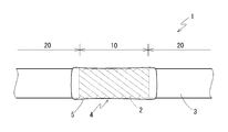
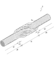
- FIGS. 1 to 3 schematically show an insulated wire 1 according to a first embodiment of the present invention and conductors 2 constituting the insulated wire 1.
- the insulated wire 1 has a conductor 2 in which a plurality of strands 2a made of a conductive material are twisted together, and an insulation coating 3 for covering the outer periphery of the conductor 2. And the water stop part 4 is formed in the middle part of the longitudinal axis direction of the insulated wire 1.
- the strands 2a constituting the conductor 2 may be made of any conductive material, but copper is generally used as the material of the conductor of the insulated wire. Besides copper, metal materials such as aluminum, magnesium and iron can also be used. These metallic materials may be alloys. Other metallic materials for alloying include iron, nickel, magnesium, silicon, combinations thereof, and the like. Even if all the strands 2a consist of the same metallic material, the strands 2a which consist of a plurality of metallic materials may be mixed.
- the twisting structure of the strands 2a in the conductor 2 is not particularly specified, but when forming the water blocking portion 4, a simple twisting structure from the viewpoint of easily widening the spacing of the strands 2a in the exposed portion 10, etc. It is preferable to have For example, it is better to have a structure in which all the strands 2a are twisted together at one time than assembling a plurality of stranded wires formed by twisting a plurality of strands 2a and further twisting them together. Further, the diameter of the entire conductor 2 and each strand 2a is not particularly specified, but the smaller the diameter of the whole conductor 2 and each strand 2a is, the smaller the distance between the strands 2a in the water blocking portion 4 is. Since the effect and significance of enhancing the reliability of water stopping by filling the sealing agent with the sealing agent is increased, it is preferable to set the conductor cross sectional area to 8 mm 2 or less and the wire diameter to 0.45 mm or less.
- the material constituting the insulation coating 3 is not particularly limited as long as it is an insulating polymer material, and polyvinyl chloride resin (PVC), an olefin resin, etc. can be mentioned.
- PVC polyvinyl chloride resin
- a filler or an additive may be contained as appropriate.
- the polymeric material may be crosslinked.
- the water blocking portion 4 includes an exposed portion 10 in which the insulating coating 3 is removed from the outer periphery of the conductor 2. Then, in the exposed portion 10, the sealing agent 5 is filled in the space between the strands 2a constituting the conductor 2.
- the sealant 5 preferably covers the outer periphery of the conductor 2 of the exposed portion 10 continuously with the space between the strands 2 a of the exposed portion 10. Furthermore, the sealing agent 5 is continuous with the space between the strands 2 a of the exposed portions 10 and the outer peripheral portion, and the outer periphery of the end portion of the covering portion 20 adjacent to both sides of the exposed portion 10, that is, the insulating coating 3 It is preferable to arrange
- the sealant 5 continues the outer periphery, preferably the entire periphery, of the region extending from the end of the covering portion 20 located on one side of the exposed portion 10 to the end of the covering portion 20 located on the other side. And covers the area between the strands 2a of the exposed portion 10 continuously with the outer peripheral portions.
- the material constituting the sealant 5 is not particularly limited as long as it is an insulating material which can not easily permeate a fluid such as water and can exhibit water fastness, but an insulating resin composition, in particular, a fluid
- an insulating resin composition in particular, a fluid
- the resin composition is placed in a state of high flowability between the strands 2a and on the outer circumference (outer circumference area) of the exposed portion 10 and the end of the covering portion 20, and then the flowability is lowered. It is possible to stably form the water blocking portion 4 with high water performance.
- a curable resin may have any one or more of curing properties such as heat curing property, photo curing property, moisture curing property, and two-component reaction curing property.
- the specific resin type which comprises the sealing agent 5 is not specifically limited.
- a silicone resin, an acrylic resin, an epoxy resin, a urethane resin etc. can be illustrated.
- Various additives may be added to these resin materials as appropriate as long as the properties of the resin material as a sealing agent are not impaired.
- the sealing agent 5 it is preferable to use a resin composition having a viscosity of 4000 mPa ⁇ s or more, more preferably 5000 mPa ⁇ s or more and 10,000 mPa ⁇ s or more in the filling state.
- a resin composition having a viscosity of 4000 mPa ⁇ s or more, more preferably 5000 mPa ⁇ s or more and 10,000 mPa ⁇ s or more in the filling state.
- the viscosity at the time of filling of the sealing agent 5 is suppressed to 200,000 mPa * s or less. If the viscosity is too high, it is difficult to sufficiently penetrate the region between the strands 2a.
- the space between the strands 2 a is stopped by filling the space between the strands 2 a of the exposed portion 10 with the sealant 5, and the water between the strands 2 a Etc. are prevented from entering from the outside.
- the sealant 5 plays a role of physically protecting the exposed portion 10 by covering the outer peripheral portion of the conductor 2 of the exposed portion 10.
- the outer periphery of the end of the covering portion 20 adjacent to the exposed portion 10 is also integrally covered, so that water blocking between the insulating covering 3 and the conductor 2, that is, water etc. in the space between the insulating covering 3 and the conductor 2 It also plays a role of preventing the infiltration of fluid from the outside.
- a sealing agent for the purpose of physical protection of the water blocking portion 94 and water blocking between the insulating coating 93 and the conductor 92.
- a protective material 99 as a separate member such as a shrinking tube was provided on the outer periphery of the portion filled with 95.
- the common sealant 5 in the outer peripheral area in addition to the area between the strands 2a, it functions as a water blocking material between the strands and as a protective material. Therefore, it is not necessary to provide another protective material on the outer periphery of the sealant 5 as a separate member.
- the configuration and manufacturing process of the water blocking portion 4 can be simplified, and the cost required for installing the protective material can be reduced.
- the diameter increase of the insulated wire 1 by a protective material and the diameter increase of the whole wire harness containing the insulated wire 1 can be avoided.
- the provision of a protective material as a separate member on the outer periphery of the sealant 5 is not hindered.
- the sealant 5 may not be disposed in the outer peripheral area but may be disposed only in the space between the strands 2a.
- the water blocking portion 4 is provided in the middle in the longitudinal axis direction of the insulated wire 1 from the viewpoint of the size of demand, the ease of widening the interval of the strands 2a, etc.
- the water blocking portion 4 may be provided at the end in the long axis direction of the insulated wire 1.
- the end of the insulated wire 1 may be in a state in which another member such as a terminal fitting is connected or in a state in which nothing is connected.
- another component such as a connection member may be included in the water blocking portion 4 coated with the sealant 5.
- a mode in which the water blocking portion 4 is provided in a splice portion in which a plurality of insulated wires 1 are joined can be mentioned.
- the density of the conductive material per unit length of the conductive material is uniform. It does not have an uneven distribution.
- Each strand 2a is provided as a continuous substantially uniform diameter wire over the entire area in the longitudinal axis direction of the insulated wire 1, and in the present specification, the density per unit length of the conductive material is between the regions.
- the different state refers to a state in which the aggregate state of the strands 2a is changed, such as the state of twisting, although the diameter and the number of the strands 2a are constant.
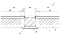
- the density of the conductive material per unit length in the conductor 2 is higher in the exposed portion 10 than in the covering portion 20.
- the covering portion 20 in the portion immediately adjacent to the exposed portion 10, there is a region (adjacent region 21) in which the density of the conductive material per unit length is lower than that of the exposed portion 10 partially. there's a possibility that.
- the density of the conductive material per unit length in the exposed portion 10 is specified in comparison with the remote region 22 excluding such an adjacent region 21 in the entire covering portion 20. ing. That is, the density of the conductive material per unit length is higher in the exposed portion 10 than in the remote area 22 of the covering portion 20.
- the state of the conductor 2 including the density of the conductive material per unit length is substantially equal to the state in the insulated wire 1 without the water blocking portion 4.
- the reason why the density of the conductive material per unit length can be lowered in the adjacent region 21 is as follows: filling of the conductive material to the exposed portion 10, continuity between the exposed portion 10 and the covering portion 20 For example, the deformation of the conductor 2 can be mentioned.
- the adjacent portion 21 can be sufficiently avoided.
- the adjacent region 21 where the density of the conductive material per unit length is locally lowered is not necessarily present, and the density of the conductive material per unit length is not provided with the water blocking portion 4 A portion not changed from the state may be directly adjacent to the exposed portion 10. That is, the density of the conductive material per unit length may be higher in the exposed portion 10 than at least the remote area 22 of the covering portion 20 sufficiently distant from the exposed portion 10.
- FIG. 1 schematically shows the state of the conductor 2 including the distribution of the density of the conductive material as described above.
- the inside of the area occupied by the conductor 2 is hatched, but the higher the density of the hatching, the smaller the twisting pitch of the strands 2 a, that is, the narrower the spacing of the strands 2 a There is.
- the wider the width (upper and lower dimensions) of the region shown as the conductor 2 is, the larger the diameter of the conductor 2 is.
- the illustrated parameters are not proportional to the twist pitch of the strands 2 a and the diameter of the conductor, but schematically show the relative magnitude relationship between the regions. Further, although the illustrated parameters are discontinuous between the respective regions, in the actual insulated wire 1, the state of the conductor 2 changes continuously between the regions.
- the diameter of the conductor 2 is larger than the remote area 22 of the covering portion 20, and the strands 2 a constituting the conductor 2 are in a bent state They are mutually fixed by the sealant 5. Due to the bending of the wire 2a, the density of the conductive material per unit length is higher in the exposed portion 10 than in the remote area 22. That is, the mass of the conductive material contained per unit length is large.
- the wire 2a is bent in a state where the diameter of the conductor 2 is expanded.
- the spacing between the strands 2a can be made wide, and a large space can be secured between the strands 2a.
- the sealant 5 can be easily permeated into the space between the strands 2a, and the sealant 5 can be easily filled with high uniformity to each part of the exposed portion 10 without unevenness. Then, in the region between the strands 2a of the exposed portion 10, highly reliable water stop can be achieved.
- the density of the conductive material per unit length in the exposed portion 10 is based on the density of the conductive material per unit length in the remote area 22. It is preferably 1.01 times or more (101% or more), more preferably 1.2 times or more (120% or more).
- the density of the conductive material per unit length in the exposed portion 10 is 1.5 times or less (150% or less) based on the density of the conductive material per unit length in the remote region 22. preferable.
- the twist pitch of the strands 2 a in the exposed portion 10 be smaller than the twist pitch in the remote area 22 of the covering portion 20.
- the twist pitch of the strands 2a is reduced and the distance between the strands 2a is also narrow, which is effective in improving the water blocking performance. That is, in the state in the middle of the formation of the water blocking portion 4 in which the space between the strands 2a is filled with the sealant 5 in a high fluidity state, the spacing between the strands 2a is narrowed. It is easy to make the stopping agent 5 uniformly stay in the space between the strands 2a without hanging down or flowing out. From the state, when the flowability of the sealant 5 is lowered by curing the curable resin or the like, high waterproof performance can be obtained in the exposed portion 10.
- the insulation coating 3 is removed in the middle of the insulated wire 1 to form an exposed portion 10 in which the conductor 2 is exposed.
- the density of the conductive material per unit length is made higher than the remote area 22 of the covering part 20, and the distance between the strands 2a is made wider than the remote area 22.
- processing is performed. Good.
- the wire 2a is drawn from the portion to be the covering portion 20, and while bending the wire 2a at the portion to be the exposed portion 10 A force may be applied to the conductor 2 so as to increase the distance between the wires.
- a method such as adjusting the method of twisting in the step of twisting the strands 2a to produce the conductor 2
- the conductor 2 having a distribution in the density of the conductive material per unit length can also be manufactured.
- the exposed portion 10 in which the density of the conductive material per unit length is increased adjacent to the covering portion 20 is formed, and in such exposed portion 10, between the strands 2a.
- the space is filled with the sealant 5.
- the sealant 5 is preferably allowed to permeate into the space between the strands 2a in a fluid state.
- the filling operation of the sealing agent 5 may be performed by dropping, coating, pouring, or any other method according to the properties of the sealing agent 5 such as the resin composition having fluidity in the space between the strands 2a. You can do it by introducing a thing.
- the amount of the sealing agent 5 introduced into the exposed portion 10 is set to an amount that causes surplus even when the space between the strands 2a is filled, and the introduction of the sealing agent 5 is It may be performed from a plurality of directions in the circumferential direction of the exposed portion 10. Under the present circumstances, it is good to add the sealing agent 5 to the outer periphery of the exposed part 10, and to arrange
- the insulating coating 3 disposed on the coated portion 20 on both sides of the exposed portion 10 is exposed before the fluidity of the sealant 5 is lowered. If it is moved toward 10, the sealant 5 can be easily disposed on the outer periphery of the insulating coating 3 at the end of the coating portion 20. In addition, if the distance between the strands 2a is narrowed while the fluidity of the sealant 5 is high, the sealant 5 can be easily retained uniformly in the space between the strands 2a.
- the density of the conductive material per unit length is high, and the distance between the strands 2a is wide. Since the sealing agent 5 is introduced to a portion where the distance between the strands 2a is increased, the sealing agent 5 can easily penetrate into the space between the strands 2a. Therefore, the sealant 5 can be easily and uniformly penetrated with high uniformity in each part of the exposed portion 10. As a result, through the curing of the sealant 5 and the like, it is possible to form a highly reliable water blocking portion 4 having excellent water blocking performance. Furthermore, even without using a special method such as the use of a pressure chamber described in Patent Document 1, the penetration of the sealant 5 with high uniformity can be easily achieved.
- sealant 5 has a high viscosity such as 4000 mPa ⁇ s or more in the filled state, and the fluidity of the sealant 5 is low, The spread of the spacing allows the sealant 5 to penetrate with high uniformity into the space between the strands 2a. If a high viscosity sealant 5 can be used, the types of usable sealants 5 are broadened.
- the sealant 5 when the sealant 5 is disposed not only in the space between the strands 2 a but also in the outer periphery of the conductor 2 of the exposed portion 10 and the outer periphery of the end of the covering portion 20, the sealant 5 flows out It is easy to stay on the outer peripheral portion of the conductor 2 without causing a drooping or the like. Therefore, it is easy to arrange the sealant 5 with high uniformity also in those outer peripheral parts.
- An insulated wire 1 '(not shown) according to the second embodiment has a conductor 2 in which a plurality of strands 2a made of a conductive material are twisted together, and an insulation coating 3 for covering the outer periphery of the conductor 2 ing.
- the water stop part 4 is formed in the middle part of the longitudinal axis direction of the insulated wire 1.
- the water blocking portion 4 includes an exposed portion 10 in which the insulating coating 3 is removed from the outer periphery of the conductor 2. Then, in the exposed portion 10, the sealing agent 5 is filled in the space between the strands 2a constituting the conductor 2.
- the sealant 5 covers the outer periphery of the conductor 2 of the exposed portion 10 continuously with the space between the strands 2 a of the exposed portion 10. Preferably, the sealant 5 covers the entire circumference of the exposed portion 10.
- the sealing agent 5 is continuous with the space between the strands 2 a of the exposed portions 10 and the outer peripheral portion, and the outer periphery of the end portion of the covering portion 20 adjacent to both sides of the exposed portion 10, that is, the insulating coating 3 It is preferable to arrange
- the sealant 5 continues the outer periphery, preferably the entire periphery, of the region extending from the end of the covering portion 20 located on one side of the exposed portion 10 to the end of the covering portion 20 located on the other side. And covers the area between the strands 2a of the exposed portion 10 continuously with the outer peripheral portions.
- the outer periphery of the exposed portion 10 in addition to the space between the strands 2a of the exposed portion 10, the outer periphery of the exposed portion 10, preferably further to the exposed portion 10 of the covering portion 20.
- the common sealant 5 is disposed on the outer periphery of the adjacent portion.
- the sealant 5 is filled between the strands 2a of the conductor 2 in the exposed portion 10, so that water blocking is performed between the strands 2a.
- the outer periphery of the exposed portion 10 preferably the outer periphery of the end portion of the covering portion 20 adjacent to the exposed portion 10 is covered with the sealant 5, so that a protective material as a separate member such as a shrinkable tube can be obtained. Even when not provided, the outer periphery of the water blocking portion 4 can be physically protected, and water blocking between the conductor 2 and the insulating coating 3 can be achieved.
- the sealing portion 4 can be configured in a simple form, and the diameter of the insulated wire 1 is increased by the protective material, and further, the diameter of the entire wire harness including the insulated wire 1 is increased. Can be avoided. Moreover, the insulated wire 1 which has such a water stop part 4 can be manufactured at the simple process which does not accompany arrangement
- a sealant having a high viscosity it is preferable to use a resin composition having a viscosity of 4000 mPa ⁇ s or more, more preferably 5000 mPa ⁇ s or more and 10,000 mPa ⁇ s or more in the filling state.
- the sealant 5 may be difficult to fill the space between the strands 2a with the sealant 5 having a high viscosity.
- the spacing between the strands 2a is increased in the exposed portion 10, for example.
- the sealant 5 can be easily permeated between the strands 2a.
- the sealant may be infiltrated using a pressure difference or a gas flow. It should be noted that if the viscosity of the sealant 5 is too high, it will be difficult for the region between the strands 2a to sufficiently penetrate even if the above method is used.
- the viscosity is preferably 200,000 mPa ⁇ s or less.
- Test method (1) Preparation of a sample An insulation coating made of polyvinyl chloride with a thickness of 0.35 mm is formed on the outer periphery of a copper stranded conductor with a conductor cross-sectional area of 0.5 mm 2 (wire diameter 0.18 mm, 20 wires). An exposed portion with a length of 8 mm was formed in the middle of the insulated wire. Then, the exposed portion was subjected to water blocking treatment to form a water blocking portion.
- wire samples having exposed portions A to C were prepared as three types of exposed portions having different densities of conductive material per unit length.
- the density (exposed area relative density) of the conductive material per unit length was 130 (average value) in the exposed area A and 101 in the exposed area B, where the density in the remote area of the coated area was 100.
- the measurement of the exposed part relative density was performed by measuring the mass of the conductor cut out to the same length from the exposed parts A and B and the covering part and calculating their ratio.
- the insulating coating of the insulated wire was simply removed, and the relative density of the exposed portion was 100.
- High viscosity sealant Moisture curable silicone resin, viscosity 5000 mPa ⁇ s (@ 23 ° C), Shin-Etsu Chemical 'KE-4895' Low viscosity sealant: moisture curable acrylic resin, viscosity 2 mPa ⁇ s (@ 23 ° C.), “7781” manufactured by Three Bond Co.
- the composition of the water blocking part in each sample is as follows.
- Sample 1 The electric wire sample having the exposed portion A was stopped using a high viscosity sealant. A layer of sealant was also formed on the outer periphery (peripheral region) of the exposed portion and the end portion of the covering portion adjacent to the exposed portion.
- Sample 2 The electric wire sample having the exposed portion A was water-stopped using a low viscosity sealant. The layer of the sealant was not formed in the outer peripheral area.
- Sample 3 A shrinkable tube with an adhesive layer was further disposed on the outer periphery of the water blocking portion of Sample 2.
- Sample 4 The electric wire sample having the exposed portion B was stopped using a low viscosity sealant. The layer of the sealant was not formed in the outer peripheral area.
- Sample 5 For a wire sample having an exposed portion C, water blocking was performed using a low viscosity sealant. The layer of the sealant was not formed in the outer peripheral area.
- air bubbles are generated from any part of the water blocking part between the strands of the water blocking part, that is, from the middle part of the water blocking part and the end of the insulated wire to which air pressure is not applied.
- it was evaluated as "(double-circle)" in which the water stop performance between strands is particularly high.
- air bubbles were generated from any of these sites by the application of an air pressure of 150 kPa, it was evaluated as "o" where the water blocking performance between the strands is high.
Landscapes
- Insulated Conductors (AREA)
Priority Applications (3)
| Application Number | Priority Date | Filing Date | Title |
|---|---|---|---|
| US16/618,995 US10978222B2 (en) | 2017-07-26 | 2018-07-13 | Insulated electric wire |
| CN201880045942.8A CN110892490B (zh) | 2017-07-26 | 2018-07-13 | 绝缘电线 |
| DE112018003812.2T DE112018003812B4 (de) | 2017-07-26 | 2018-07-13 | Isolierter elektrischer Draht |
Applications Claiming Priority (2)
| Application Number | Priority Date | Filing Date | Title |
|---|---|---|---|
| JP2017144606A JP6525032B2 (ja) | 2017-07-26 | 2017-07-26 | 絶縁電線 |
| JP2017-144606 | 2017-07-26 |
Publications (1)
| Publication Number | Publication Date |
|---|---|
| WO2019021850A1 true WO2019021850A1 (ja) | 2019-01-31 |
Family
ID=65039713
Family Applications (1)
| Application Number | Title | Priority Date | Filing Date |
|---|---|---|---|
| PCT/JP2018/026424 Ceased WO2019021850A1 (ja) | 2017-07-26 | 2018-07-13 | 絶縁電線 |
Country Status (5)
| Country | Link |
|---|---|
| US (1) | US10978222B2 (enExample) |
| JP (1) | JP6525032B2 (enExample) |
| CN (1) | CN110892490B (enExample) |
| DE (1) | DE112018003812B4 (enExample) |
| WO (1) | WO2019021850A1 (enExample) |
Cited By (5)
| Publication number | Priority date | Publication date | Assignee | Title |
|---|---|---|---|---|
| US20220028581A1 (en) * | 2019-01-30 | 2022-01-27 | Autonetworks Technologies, Ltd. | Insulated electric wire, wire harness, and insulated electric wire production method |
| CN114156005A (zh) * | 2021-11-11 | 2022-03-08 | 江苏永鼎电气有限公司 | 一种高温封胶导体及其在汽车线束中的应用 |
| US20220157491A1 (en) * | 2019-01-30 | 2022-05-19 | Autonetworks Technologies, Ltd. | Insulated electric wire and wire harness |
| US20220165453A1 (en) * | 2019-01-30 | 2022-05-26 | Autonetworks Technologies, Ltd. | Insulated electric wire and wire harness |
| US11887757B2 (en) | 2019-01-30 | 2024-01-30 | Autonetworks Technologies, Ltd. | Insulated electric wire and wire harness |
Families Citing this family (2)
| Publication number | Priority date | Publication date | Assignee | Title |
|---|---|---|---|---|
| JP6525032B2 (ja) | 2017-07-26 | 2019-06-05 | 株式会社オートネットワーク技術研究所 | 絶縁電線 |
| JP6798438B2 (ja) | 2017-07-26 | 2020-12-09 | 株式会社オートネットワーク技術研究所 | 絶縁電線の製造方法および絶縁電線 |
Citations (3)
| Publication number | Priority date | Publication date | Assignee | Title |
|---|---|---|---|---|
| JP2000011771A (ja) * | 1998-06-22 | 2000-01-14 | Furukawa Electric Co Ltd:The | 止水部付き電線とその製造方法 |
| DE102011083952A1 (de) * | 2011-10-04 | 2013-04-04 | Sumitomo Electric Bordnetze Gmbh | Verfahren zur Herstellung einer längswasserdichten Anordnung |
| JP2013097922A (ja) * | 2011-10-28 | 2013-05-20 | Yazaki Corp | 芯線止水構造及び芯線止水方法 |
Family Cites Families (16)
| Publication number | Priority date | Publication date | Assignee | Title |
|---|---|---|---|---|
| JPS56156616A (en) | 1980-04-15 | 1981-12-03 | Furukawa Electric Co Ltd | Method of manufacturing dam for communication cable |
| JP2584507Y2 (ja) * | 1993-05-24 | 1998-11-05 | 住友電装株式会社 | 電線の防水構造 |
| JP3129936B2 (ja) | 1995-06-12 | 2001-01-31 | 矢崎総業株式会社 | グロメット止水方法及びグロメット止水用治具 |
| EP1953770B1 (en) * | 2005-11-02 | 2011-06-29 | Autonetworks Technologies, Ltd. | Method for water stopping in on-vehicle electric wires |
| JP4918248B2 (ja) | 2005-11-16 | 2012-04-18 | 矢崎総業株式会社 | 線間止水方法、線間止水装置、およびワイヤハーネス |
| JP5304001B2 (ja) | 2007-11-08 | 2013-10-02 | 住友電装株式会社 | 電線の止水方法及び該止水方法で形成された止水部を有する電線 |
| JP5176533B2 (ja) | 2007-12-19 | 2013-04-03 | 住友電装株式会社 | 電線の止水方法及び該止水方法で形成された止水部を有する電線 |
| US8502072B2 (en) | 2009-05-29 | 2013-08-06 | General Dynamics Advanced Information Systems, Inc. | Spliced cable with overmolded water proof coating and method for making the same |
| JP2011001566A (ja) * | 2009-06-16 | 2011-01-06 | Autonetworks Technologies Ltd | 電線導体および自動車用電線 |
| KR20140002014A (ko) | 2011-04-29 | 2014-01-07 | 스미토모 덴키 고교 가부시키가이샤 | 소경 케이블 하네스 및 그것의 제조 방법 |
| US8600213B2 (en) | 2011-10-26 | 2013-12-03 | Xerox Corporation | Filtering source video data via independent component selection |
| CN202930077U (zh) * | 2012-12-12 | 2013-05-08 | 西安飞机工业(集团)亨通航空电子有限公司 | 一种高强度自漂浮水上用油气电主干线软综合缆 |
| US10373738B2 (en) * | 2015-05-08 | 2019-08-06 | Radix Wire & Cable, Llc | Insulated wire construction with liner |
| CN205069160U (zh) * | 2015-10-13 | 2016-03-02 | 东莞宝特电业有限公司 | 高绝缘性电线 |
| US11239639B2 (en) * | 2016-09-30 | 2022-02-01 | TE Connectivity Services Gmbh | Assembly and method for sealing a bundle of wires |
| JP6525032B2 (ja) | 2017-07-26 | 2019-06-05 | 株式会社オートネットワーク技術研究所 | 絶縁電線 |
-
2017
- 2017-07-26 JP JP2017144606A patent/JP6525032B2/ja active Active
-
2018
- 2018-07-13 CN CN201880045942.8A patent/CN110892490B/zh active Active
- 2018-07-13 US US16/618,995 patent/US10978222B2/en active Active
- 2018-07-13 WO PCT/JP2018/026424 patent/WO2019021850A1/ja not_active Ceased
- 2018-07-13 DE DE112018003812.2T patent/DE112018003812B4/de active Active
Patent Citations (3)
| Publication number | Priority date | Publication date | Assignee | Title |
|---|---|---|---|---|
| JP2000011771A (ja) * | 1998-06-22 | 2000-01-14 | Furukawa Electric Co Ltd:The | 止水部付き電線とその製造方法 |
| DE102011083952A1 (de) * | 2011-10-04 | 2013-04-04 | Sumitomo Electric Bordnetze Gmbh | Verfahren zur Herstellung einer längswasserdichten Anordnung |
| JP2013097922A (ja) * | 2011-10-28 | 2013-05-20 | Yazaki Corp | 芯線止水構造及び芯線止水方法 |
Cited By (9)
| Publication number | Priority date | Publication date | Assignee | Title |
|---|---|---|---|---|
| US20220028581A1 (en) * | 2019-01-30 | 2022-01-27 | Autonetworks Technologies, Ltd. | Insulated electric wire, wire harness, and insulated electric wire production method |
| US20220157491A1 (en) * | 2019-01-30 | 2022-05-19 | Autonetworks Technologies, Ltd. | Insulated electric wire and wire harness |
| US20220165453A1 (en) * | 2019-01-30 | 2022-05-26 | Autonetworks Technologies, Ltd. | Insulated electric wire and wire harness |
| US11887758B2 (en) * | 2019-01-30 | 2024-01-30 | Autonetworks Technologies, Ltd. | Wire harness and insulated electric wire thereof having water-stopping agent |
| US11887759B2 (en) | 2019-01-30 | 2024-01-30 | Autonetworks Technologies, Ltd. | Insulated electric wire with water-stopping agent, wire harness, and insulated electric wire production method |
| US11887757B2 (en) | 2019-01-30 | 2024-01-30 | Autonetworks Technologies, Ltd. | Insulated electric wire and wire harness |
| US11908598B2 (en) * | 2019-01-30 | 2024-02-20 | Autonetworks Technologies, Ltd. | Insulated electric wire and harness with water-stopping agent and wire harness |
| US12249444B2 (en) * | 2019-01-30 | 2025-03-11 | Autonetworks Technologies, Ltd. | Insulated electric wire and wire harness |
| CN114156005A (zh) * | 2021-11-11 | 2022-03-08 | 江苏永鼎电气有限公司 | 一种高温封胶导体及其在汽车线束中的应用 |
Also Published As
| Publication number | Publication date |
|---|---|
| JP6525032B2 (ja) | 2019-06-05 |
| DE112018003812T5 (de) | 2020-04-09 |
| JP2019029093A (ja) | 2019-02-21 |
| US10978222B2 (en) | 2021-04-13 |
| CN110892490A (zh) | 2020-03-17 |
| CN110892490B (zh) | 2021-01-08 |
| DE112018003812B4 (de) | 2021-09-30 |
| US20200381141A1 (en) | 2020-12-03 |
Similar Documents
| Publication | Publication Date | Title |
|---|---|---|
| JP6525032B2 (ja) | 絶縁電線 | |
| US11657928B2 (en) | Production method for insulated electric wire and insulated electric wire | |
| CN113366588B (zh) | 绝缘电线及线束 | |
| JP7226456B2 (ja) | 絶縁電線、ワイヤーハーネス、絶縁電線の製造方法 | |
| WO2020158445A1 (ja) | 絶縁電線およびワイヤーハーネス | |
| CN113316828A (zh) | 绝缘电线及线束 | |
| WO2019188062A1 (ja) | 電線の防水構造 | |
| JP2014220097A (ja) | 端子付電線 | |
| JP7298756B2 (ja) | 絶縁電線の製造方法および絶縁電線 | |
| JP7390132B2 (ja) | ワイヤーハーネス | |
| JP7095727B2 (ja) | 絶縁電線の製造方法および絶縁電線 | |
| JP7543765B2 (ja) | 絶縁電線、ワイヤーハーネス、絶縁電線の製造方法 | |
| JP5847621B2 (ja) | 圧着端子を電線に圧着する方法 | |
| JP2015105407A (ja) | 端子付き被覆電線及びワイヤーハーネス | |
| JP2014128135A (ja) | 電力ケーブルの接続方法及び接続構造 | |
| JP2014191989A (ja) | 端子付電線 | |
| JP2009283341A (ja) | 電線スプライス部の防水構造 | |
| JP2010055820A (ja) | コード状ヒータとリード線の電気的接続構造及び電気的接続方法 |
Legal Events
| Date | Code | Title | Description |
|---|---|---|---|
| 121 | Ep: the epo has been informed by wipo that ep was designated in this application |
Ref document number: 18838863 Country of ref document: EP Kind code of ref document: A1 |
|
| 122 | Ep: pct application non-entry in european phase |
Ref document number: 18838863 Country of ref document: EP Kind code of ref document: A1 |