WO2019021732A1 - 燃料噴射制御装置及び燃料噴射制御方法 - Google Patents
燃料噴射制御装置及び燃料噴射制御方法 Download PDFInfo
- Publication number
- WO2019021732A1 WO2019021732A1 PCT/JP2018/024485 JP2018024485W WO2019021732A1 WO 2019021732 A1 WO2019021732 A1 WO 2019021732A1 JP 2018024485 W JP2018024485 W JP 2018024485W WO 2019021732 A1 WO2019021732 A1 WO 2019021732A1
- Authority
- WO
- WIPO (PCT)
- Prior art keywords
- energization
- period
- valve
- movable core
- valve body
- Prior art date
Links
Images


Classifications
-
- F—MECHANICAL ENGINEERING; LIGHTING; HEATING; WEAPONS; BLASTING
- F01—MACHINES OR ENGINES IN GENERAL; ENGINE PLANTS IN GENERAL; STEAM ENGINES
- F01L—CYCLICALLY OPERATING VALVES FOR MACHINES OR ENGINES
- F01L9/00—Valve-gear or valve arrangements actuated non-mechanically
- F01L9/20—Valve-gear or valve arrangements actuated non-mechanically by electric means
-
- F—MECHANICAL ENGINEERING; LIGHTING; HEATING; WEAPONS; BLASTING
- F02—COMBUSTION ENGINES; HOT-GAS OR COMBUSTION-PRODUCT ENGINE PLANTS
- F02D—CONTROLLING COMBUSTION ENGINES
- F02D41/00—Electrical control of supply of combustible mixture or its constituents
- F02D41/30—Controlling fuel injection
- F02D41/38—Controlling fuel injection of the high pressure type
- F02D41/40—Controlling fuel injection of the high pressure type with means for controlling injection timing or duration
- F02D41/402—Multiple injections
-
- F—MECHANICAL ENGINEERING; LIGHTING; HEATING; WEAPONS; BLASTING
- F01—MACHINES OR ENGINES IN GENERAL; ENGINE PLANTS IN GENERAL; STEAM ENGINES
- F01L—CYCLICALLY OPERATING VALVES FOR MACHINES OR ENGINES
- F01L9/00—Valve-gear or valve arrangements actuated non-mechanically
- F01L9/20—Valve-gear or valve arrangements actuated non-mechanically by electric means
- F01L9/21—Valve-gear or valve arrangements actuated non-mechanically by electric means actuated by solenoids
-
- F—MECHANICAL ENGINEERING; LIGHTING; HEATING; WEAPONS; BLASTING
- F02—COMBUSTION ENGINES; HOT-GAS OR COMBUSTION-PRODUCT ENGINE PLANTS
- F02D—CONTROLLING COMBUSTION ENGINES
- F02D41/00—Electrical control of supply of combustible mixture or its constituents
- F02D41/20—Output circuits, e.g. for controlling currents in command coils
-
- F—MECHANICAL ENGINEERING; LIGHTING; HEATING; WEAPONS; BLASTING
- F02—COMBUSTION ENGINES; HOT-GAS OR COMBUSTION-PRODUCT ENGINE PLANTS
- F02M—SUPPLYING COMBUSTION ENGINES IN GENERAL WITH COMBUSTIBLE MIXTURES OR CONSTITUENTS THEREOF
- F02M51/00—Fuel-injection apparatus characterised by being operated electrically
- F02M51/06—Injectors peculiar thereto with means directly operating the valve needle
- F02M51/061—Injectors peculiar thereto with means directly operating the valve needle using electromagnetic operating means
- F02M51/0625—Injectors peculiar thereto with means directly operating the valve needle using electromagnetic operating means characterised by arrangement of mobile armatures
- F02M51/0635—Injectors peculiar thereto with means directly operating the valve needle using electromagnetic operating means characterised by arrangement of mobile armatures having a plate-shaped or undulated armature not entering the winding
- F02M51/0642—Injectors peculiar thereto with means directly operating the valve needle using electromagnetic operating means characterised by arrangement of mobile armatures having a plate-shaped or undulated armature not entering the winding the armature having a valve attached thereto
- F02M51/0653—Injectors peculiar thereto with means directly operating the valve needle using electromagnetic operating means characterised by arrangement of mobile armatures having a plate-shaped or undulated armature not entering the winding the armature having a valve attached thereto the valve being an elongated body, e.g. a needle valve
-
- F—MECHANICAL ENGINEERING; LIGHTING; HEATING; WEAPONS; BLASTING
- F02—COMBUSTION ENGINES; HOT-GAS OR COMBUSTION-PRODUCT ENGINE PLANTS
- F02M—SUPPLYING COMBUSTION ENGINES IN GENERAL WITH COMBUSTIBLE MIXTURES OR CONSTITUENTS THEREOF
- F02M51/00—Fuel-injection apparatus characterised by being operated electrically
- F02M51/06—Injectors peculiar thereto with means directly operating the valve needle
- F02M51/061—Injectors peculiar thereto with means directly operating the valve needle using electromagnetic operating means
- F02M51/0625—Injectors peculiar thereto with means directly operating the valve needle using electromagnetic operating means characterised by arrangement of mobile armatures
- F02M51/0635—Injectors peculiar thereto with means directly operating the valve needle using electromagnetic operating means characterised by arrangement of mobile armatures having a plate-shaped or undulated armature not entering the winding
- F02M51/066—Injectors peculiar thereto with means directly operating the valve needle using electromagnetic operating means characterised by arrangement of mobile armatures having a plate-shaped or undulated armature not entering the winding the armature and the valve being allowed to move relatively to each other or not being attached to each other
-
- F—MECHANICAL ENGINEERING; LIGHTING; HEATING; WEAPONS; BLASTING
- F02—COMBUSTION ENGINES; HOT-GAS OR COMBUSTION-PRODUCT ENGINE PLANTS
- F02M—SUPPLYING COMBUSTION ENGINES IN GENERAL WITH COMBUSTIBLE MIXTURES OR CONSTITUENTS THEREOF
- F02M51/00—Fuel-injection apparatus characterised by being operated electrically
- F02M51/06—Injectors peculiar thereto with means directly operating the valve needle
- F02M51/061—Injectors peculiar thereto with means directly operating the valve needle using electromagnetic operating means
- F02M51/0625—Injectors peculiar thereto with means directly operating the valve needle using electromagnetic operating means characterised by arrangement of mobile armatures
- F02M51/0664—Injectors peculiar thereto with means directly operating the valve needle using electromagnetic operating means characterised by arrangement of mobile armatures having a cylindrically or partly cylindrically shaped armature, e.g. entering the winding; having a plate-shaped or undulated armature entering the winding
- F02M51/0685—Injectors peculiar thereto with means directly operating the valve needle using electromagnetic operating means characterised by arrangement of mobile armatures having a cylindrically or partly cylindrically shaped armature, e.g. entering the winding; having a plate-shaped or undulated armature entering the winding the armature and the valve being allowed to move relatively to each other or not being attached to each other
-
- F—MECHANICAL ENGINEERING; LIGHTING; HEATING; WEAPONS; BLASTING
- F02—COMBUSTION ENGINES; HOT-GAS OR COMBUSTION-PRODUCT ENGINE PLANTS
- F02P—IGNITION, OTHER THAN COMPRESSION IGNITION, FOR INTERNAL-COMBUSTION ENGINES; TESTING OF IGNITION TIMING IN COMPRESSION-IGNITION ENGINES
- F02P5/00—Advancing or retarding ignition; Control therefor
- F02P5/04—Advancing or retarding ignition; Control therefor automatically, as a function of the working conditions of the engine or vehicle or of the atmospheric conditions
- F02P5/145—Advancing or retarding ignition; Control therefor automatically, as a function of the working conditions of the engine or vehicle or of the atmospheric conditions using electrical means
-
- F—MECHANICAL ENGINEERING; LIGHTING; HEATING; WEAPONS; BLASTING
- F16—ENGINEERING ELEMENTS AND UNITS; GENERAL MEASURES FOR PRODUCING AND MAINTAINING EFFECTIVE FUNCTIONING OF MACHINES OR INSTALLATIONS; THERMAL INSULATION IN GENERAL
- F16K—VALVES; TAPS; COCKS; ACTUATING-FLOATS; DEVICES FOR VENTING OR AERATING
- F16K31/00—Actuating devices; Operating means; Releasing devices
- F16K31/02—Actuating devices; Operating means; Releasing devices electric; magnetic
- F16K31/06—Actuating devices; Operating means; Releasing devices electric; magnetic using a magnet, e.g. diaphragm valves, cutting off by means of a liquid
- F16K31/0675—Electromagnet aspects, e.g. electric supply therefor
-
- F—MECHANICAL ENGINEERING; LIGHTING; HEATING; WEAPONS; BLASTING
- F01—MACHINES OR ENGINES IN GENERAL; ENGINE PLANTS IN GENERAL; STEAM ENGINES
- F01L—CYCLICALLY OPERATING VALVES FOR MACHINES OR ENGINES
- F01L9/00—Valve-gear or valve arrangements actuated non-mechanically
- F01L9/20—Valve-gear or valve arrangements actuated non-mechanically by electric means
- F01L9/21—Valve-gear or valve arrangements actuated non-mechanically by electric means actuated by solenoids
- F01L2009/2103—Valve-gear or valve arrangements actuated non-mechanically by electric means actuated by solenoids comprising one coil
-
- F—MECHANICAL ENGINEERING; LIGHTING; HEATING; WEAPONS; BLASTING
- F01—MACHINES OR ENGINES IN GENERAL; ENGINE PLANTS IN GENERAL; STEAM ENGINES
- F01L—CYCLICALLY OPERATING VALVES FOR MACHINES OR ENGINES
- F01L2710/00—Control of valve gear, speed or power
-
- F—MECHANICAL ENGINEERING; LIGHTING; HEATING; WEAPONS; BLASTING
- F02—COMBUSTION ENGINES; HOT-GAS OR COMBUSTION-PRODUCT ENGINE PLANTS
- F02B—INTERNAL-COMBUSTION PISTON ENGINES; COMBUSTION ENGINES IN GENERAL
- F02B75/00—Other engines
- F02B75/12—Other methods of operation
- F02B2075/125—Direct injection in the combustion chamber for spark ignition engines, i.e. not in pre-combustion chamber
-
- F—MECHANICAL ENGINEERING; LIGHTING; HEATING; WEAPONS; BLASTING
- F02—COMBUSTION ENGINES; HOT-GAS OR COMBUSTION-PRODUCT ENGINE PLANTS
- F02D—CONTROLLING COMBUSTION ENGINES
- F02D41/00—Electrical control of supply of combustible mixture or its constituents
- F02D41/20—Output circuits, e.g. for controlling currents in command coils
- F02D2041/2003—Output circuits, e.g. for controlling currents in command coils using means for creating a boost voltage, i.e. generation or use of a voltage higher than the battery voltage, e.g. to speed up injector opening
-
- F—MECHANICAL ENGINEERING; LIGHTING; HEATING; WEAPONS; BLASTING
- F02—COMBUSTION ENGINES; HOT-GAS OR COMBUSTION-PRODUCT ENGINE PLANTS
- F02D—CONTROLLING COMBUSTION ENGINES
- F02D41/00—Electrical control of supply of combustible mixture or its constituents
- F02D41/20—Output circuits, e.g. for controlling currents in command coils
- F02D2041/202—Output circuits, e.g. for controlling currents in command coils characterised by the control of the circuit
- F02D2041/2037—Output circuits, e.g. for controlling currents in command coils characterised by the control of the circuit for preventing bouncing of the valve needle
-
- F—MECHANICAL ENGINEERING; LIGHTING; HEATING; WEAPONS; BLASTING
- F02—COMBUSTION ENGINES; HOT-GAS OR COMBUSTION-PRODUCT ENGINE PLANTS
- F02D—CONTROLLING COMBUSTION ENGINES
- F02D41/00—Electrical control of supply of combustible mixture or its constituents
- F02D41/20—Output circuits, e.g. for controlling currents in command coils
- F02D2041/202—Output circuits, e.g. for controlling currents in command coils characterised by the control of the circuit
- F02D2041/2044—Output circuits, e.g. for controlling currents in command coils characterised by the control of the circuit using pre-magnetisation or post-magnetisation of the coils
-
- F—MECHANICAL ENGINEERING; LIGHTING; HEATING; WEAPONS; BLASTING
- F02—COMBUSTION ENGINES; HOT-GAS OR COMBUSTION-PRODUCT ENGINE PLANTS
- F02D—CONTROLLING COMBUSTION ENGINES
- F02D41/00—Electrical control of supply of combustible mixture or its constituents
- F02D41/30—Controlling fuel injection
- F02D41/38—Controlling fuel injection of the high pressure type
- F02D2041/389—Controlling fuel injection of the high pressure type for injecting directly into the cylinder
-
- F—MECHANICAL ENGINEERING; LIGHTING; HEATING; WEAPONS; BLASTING
- F02—COMBUSTION ENGINES; HOT-GAS OR COMBUSTION-PRODUCT ENGINE PLANTS
- F02D—CONTROLLING COMBUSTION ENGINES
- F02D2200/00—Input parameters for engine control
- F02D2200/02—Input parameters for engine control the parameters being related to the engine
- F02D2200/06—Fuel or fuel supply system parameters
- F02D2200/063—Lift of the valve needle
-
- F—MECHANICAL ENGINEERING; LIGHTING; HEATING; WEAPONS; BLASTING
- F02—COMBUSTION ENGINES; HOT-GAS OR COMBUSTION-PRODUCT ENGINE PLANTS
- F02D—CONTROLLING COMBUSTION ENGINES
- F02D41/00—Electrical control of supply of combustible mixture or its constituents
- F02D41/30—Controlling fuel injection
- F02D41/38—Controlling fuel injection of the high pressure type
- F02D41/40—Controlling fuel injection of the high pressure type with means for controlling injection timing or duration
- F02D41/401—Controlling injection timing
-
- Y—GENERAL TAGGING OF NEW TECHNOLOGICAL DEVELOPMENTS; GENERAL TAGGING OF CROSS-SECTIONAL TECHNOLOGIES SPANNING OVER SEVERAL SECTIONS OF THE IPC; TECHNICAL SUBJECTS COVERED BY FORMER USPC CROSS-REFERENCE ART COLLECTIONS [XRACs] AND DIGESTS
- Y02—TECHNOLOGIES OR APPLICATIONS FOR MITIGATION OR ADAPTATION AGAINST CLIMATE CHANGE
- Y02T—CLIMATE CHANGE MITIGATION TECHNOLOGIES RELATED TO TRANSPORTATION
- Y02T10/00—Road transport of goods or passengers
- Y02T10/10—Internal combustion engine [ICE] based vehicles
- Y02T10/12—Improving ICE efficiencies
-
- Y—GENERAL TAGGING OF NEW TECHNOLOGICAL DEVELOPMENTS; GENERAL TAGGING OF CROSS-SECTIONAL TECHNOLOGIES SPANNING OVER SEVERAL SECTIONS OF THE IPC; TECHNICAL SUBJECTS COVERED BY FORMER USPC CROSS-REFERENCE ART COLLECTIONS [XRACs] AND DIGESTS
- Y02—TECHNOLOGIES OR APPLICATIONS FOR MITIGATION OR ADAPTATION AGAINST CLIMATE CHANGE
- Y02T—CLIMATE CHANGE MITIGATION TECHNOLOGIES RELATED TO TRANSPORTATION
- Y02T10/00—Road transport of goods or passengers
- Y02T10/10—Internal combustion engine [ICE] based vehicles
- Y02T10/40—Engine management systems
Definitions
- the disclosure of this specification relates to a fuel injection control device and a fuel injection control method.
- the fuel injection valve includes a movable core moved by an electromagnetic attraction force generated as the coil is energized, and a valve body opened as the movable core moves.
- the movable core and the valve body There is a fuel injection valve that is capable of relative movement with the For example, according to Patent Document 1, even if the valve body moving in the valve closing direction for closing the injection hole is stopped at the valve closing position, the movable core is stopped at the initial position corresponding to the valve closing position of the valve body. Instead, a configuration is disclosed in which the movement in the valve closing direction is continued as a relative movement with respect to the valve body.
- the state where the movable core is on the valve closing side rather than the initial position despite the valve body stopping at the valve closing position is referred to as an undershoot, and the electromagnetic attraction force generated with the next energization of the coil As a result, the moving coil in the undershoot may be sucked.
- the movable core in the undershoot is forcibly pulled back in the valve opening direction by the electromagnetic attraction force, so that the movable core passes to the valve opening side without being stopped at the initial position.
- the inventor immediately closes the moving direction even if the movable core passes the initial position to the valve opening side. We got the knowledge that it changed to the direction and returned to the initial position. As described above, if the movable core is moved to the valve opening side unintentionally temporarily than the initial position, there is a possibility that an irregular injection may be generated in which the fuel is temporarily injected unintentionally.
- An object of the present disclosure is to provide a fuel injection control device and a fuel injection control method capable of suppressing the occurrence of irregular injection in which fuel is temporarily injected unintentionally.
- a fuel injection control device generates an electromagnetic attraction force with energization to a coil, an injection hole for injecting fuel, a valve body that opens the injection hole by moving in a valve-opening direction, A fixed core, and a movable core capable of relative movement with respect to the valve body and moving the valve body in the valve opening direction by being attracted to the fixed core from a predetermined initial position and moving in the valve opening direction;
- the movable core is opened when the rising period required for rising of the electromagnetic attraction force accompanying the energization elapses, and the valve core biasing portion biases the valve body in the valve closing direction opposite to the valve opening direction.
- valve body moves in the valve closing direction by moving in the valve closing direction by the biasing force of the valve body urging portion, thereby moving the movable core in the valve closing direction, and the valve body moving in the valve closing direction stops.
- the movable core Is a fuel injection control device applied to the fuel injection valve that changes the moving direction to the valve opening direction and returns to the initial position, wherein the undershoot generated by the first energization for fuel injection is movable from the first energization to the first
- the period expected to be required for the core to return to the initial position is referred to as the return period
- the period from the first energization to the second energization for the next fuel injection is referred to as the injection interval
- the second energization is predicted.
- the value obtained by subtracting the rise time from the return period is referred to as the allowable period.
- additional energization is added between the first energization and the second energization. And an additional energizing unit.
- the inventor easily accelerates the movable core in the undershoot by electromagnetic attraction and tends to generate irregular injection of fuel. I got the knowledge that. According to this finding, when the electromagnetic attraction is applied to the movable core moving in the valve opening direction by the core boost in the undershoot, the movable core in the core boost can be the core boost even if the electromagnetic attraction does not rise sufficiently. Be accelerated.
- the force of the movable core tends to cause the valve body to move unintendedly in the valve opening direction with the movable core.
- the movable core which has moved to the valve-opening side from the initial position changes the movement direction to the valve-closing direction by the fact that the electromagnetic attraction force which does not stand up enough loses the urging force of the valve body urging portion. The valve is closed accordingly. Thus, it is considered that the irregular injection of fuel occurs.
- the first aspect when the injection interval is equal to or greater than the allowable period and equal to or less than the return period, additional energization is performed between the first energization and the second energization.
- the movable core is accelerated by the electromagnetic attraction force and the actual return period is shortened, it is possible to make the actual return period shorter than the injection interval. That is, it is possible to avoid the occurrence condition of the irregular injection that the injection interval is equal to or less than the return period. Therefore, it can suppress that irregular injection generate
- a fuel injection control device generates an electromagnetic attraction force with energization to a coil, an injection hole for injecting fuel, a valve body for opening the injection hole by moving in a valve-opening direction, A fixed core, and a movable core capable of relative movement with respect to the valve body and moving the valve body in the valve opening direction by being attracted to the fixed core from a predetermined initial position and moving in the valve opening direction;
- the movable core is opened when the rising period required for rising of the electromagnetic attraction force accompanying the energization elapses, and the valve core biasing portion biases the valve body in the valve closing direction opposite to the valve opening direction.
- the movement in the valve direction is started, and the valve body moves in the valve closing direction by moving in the valve closing direction by the biasing force of the valve body urging portion, thereby moving the movable core in the valve closing direction, and the valve body moving in the valve closing direction stops.
- the movable core Is a fuel injection control device applied to the fuel injection valve that changes the moving direction to the valve opening direction and returns to the initial position, wherein the movable core is at the initial position with respect to the undershoot generated by the first energization for fuel injection.
- an additional energizing unit is added to add to the return timing expected to return to the second fuel injection.
- the present inventor has found that there is a condition that the return timing of the undershoot generated by the first energization is included in the rising period of the second energization as a condition that causes the irregular injection of the fuel. If this condition is satisfied, it is considered that the irregular injection of fuel occurs as in the description of the first aspect.
- the actual return timing can be advanced by accelerating the movable core by the electromagnetic attraction force, so that the actual return timing can be made earlier than the rising period of the second energization. That is, it is possible to avoid the occurrence condition of the irregular injection that the return timing by the first energization is included in the rising period of the second energization. Therefore, as in the first aspect, the occurrence of the irregular injection can be suppressed.
- a fuel injection control device generates an electromagnetic attraction force with energization to a coil, an injection hole that injects fuel, a valve body that opens the injection hole by moving in a valve-opening direction, A fixed core, and a movable core capable of relative movement with respect to the valve body and moving the valve body in the valve opening direction by being attracted to the fixed core from a predetermined initial position and moving in the valve opening direction;
- the movable core is opened when the rising period required for rising of the electromagnetic attraction force accompanying the energization elapses, and the valve core biasing portion biases the valve body in the valve closing direction opposite to the valve opening direction.
- valve body moves in the valve closing direction by moving in the valve closing direction by the biasing force of the valve body urging portion, thereby moving the movable core in the valve closing direction, and the valve body moving in the valve closing direction stops.
- the movable core Is a fuel injection control device applied to the fuel injection valve that changes the moving direction to the valve opening direction and returns to the initial position, wherein the undershoot generated by the first energization for fuel injection is movable from the first energization to the first
- the period expected to be required for the core to return to the initial position is referred to as the return period
- the period from the first energization to the second energization for the next fuel injection is referred to as the injection interval
- the second energization is predicted.
- the value obtained by subtracting the rising period from the return period is referred to as the allowable period.
- a change electrification unit is configured to change the mode of the second energization so as to be shorter than the period or shorter than the return period.
- the rising period for the second energization is compared with the case not corresponding to this condition. And be shortened. For this reason, when it corresponds to the irregular condition, the allowable period becomes longer as the rising period for the second energization becomes shorter.
- the electromagnetic attraction force sharply increases even if the allowable period does not become longer than the injection interval. Movement of the movable core in the valve opening direction is likely to be continued. In this case, it is possible to suppress that the movable core which has passed the initial position by the force of the undershoot changes the moving direction and returns to the initial position again. Therefore, it can suppress that irregular injection generate
- a fuel injection control device generates an electromagnetic attraction force with energization to a coil, an injection hole for injecting fuel, a valve body that opens the injection hole by moving in a valve-opening direction, A fixed core, and a movable core capable of relative movement with respect to the valve body and moving the valve body in the valve opening direction by being attracted to the fixed core from a predetermined initial position and moving in the valve opening direction;
- the movable core is opened when the rising period required for rising of the electromagnetic attraction force accompanying the energization elapses, and the valve core biasing portion biases the valve body in the valve closing direction opposite to the valve opening direction.
- valve body moves in the valve closing direction by moving in the valve closing direction by the biasing force of the valve body urging portion, thereby moving the movable core in the valve closing direction, and the valve body moving in the valve closing direction stops.
- the movable core Is a fuel injection control device applied to the fuel injection valve that changes the moving direction to the valve opening direction and returns to the initial position, wherein the undershoot generated by the first energization for fuel injection is movable from the first energization to the first
- the period expected to be required for the core to return to the initial position is referred to as the return period
- the period from the first energization to the second energization for the next fuel injection is referred to as the injection interval
- the second energization is predicted.
- the value obtained by subtracting the rising period from the return period is referred to as the allowable period.
- the second energization is started earlier than the second energization. It has a pre-energization part which adds pre-energization continued until it is started.
- the degree of increase of the current flowing through the coil by the second energization increases with the shortening of the rising period, so that the occurrence of the irregular injection of the fuel can be suppressed.
- an electromagnetic attraction force is generated along with energization of a coil, an injection hole for injecting fuel, a valve body that opens the injection hole by moving in a valve opening direction, A fixed core, and a movable core capable of relative movement with respect to the valve body and moving the valve body in the valve opening direction by being attracted to the fixed core from a predetermined initial position and moving in the valve opening direction;
- the movable core is opened when the rising period required for rising of the electromagnetic attraction force accompanying the energization elapses, and the valve core biasing portion biases the valve body in the valve closing direction opposite to the valve opening direction.
- valve body moves in the valve closing direction by moving in the valve closing direction by the biasing force of the valve body urging portion, thereby moving the movable core in the valve closing direction, and the valve body moving in the valve closing direction stops.
- the movable core Is the fuel injection control method applied to the fuel injection valve that changes the moving direction to the valve opening direction and returns to the initial position, and the first through the movable for the undershoot generated by the first current supply for fuel injection
- the period expected to be required for the core to return to the initial position is referred to as the return period
- the period from the first energization to the second energization for the next fuel injection is referred to as the injection interval
- the second energization is predicted.
- the value obtained by subtracting the rising period of the electromagnetic attraction force from the return period is referred to as the allowable period. If the injection interval is equal to or greater than the allowable period and equal to or smaller than the return period, It is a fuel injection control method which adds additional energization.
- FIG. 1 is a schematic view showing a configuration of a combustion system in a first embodiment
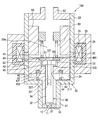
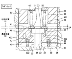
- FIG. 2 is a schematic vertical sectional view showing the configuration of a fuel injection valve
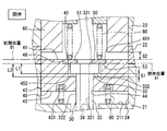
- FIG. 3 is a view showing an open state of the fuel injection valve
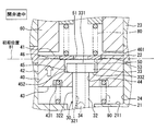
- FIG. 4 is a view showing a state during the opening of the fuel injection valve
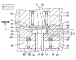
- FIG. 5 is a view showing a state in which the fuel injection valve has been opened
- FIG. 6 is a view showing a state in which the needle of the fuel injection valve overshoots
- FIG. 7 is a view showing a state where the movable core of the fuel injection valve undershoots
- FIG. 1 is a schematic view showing a configuration of a combustion system in a first embodiment
- FIG. 2 is a schematic vertical sectional view showing the configuration of a fuel injection valve
- FIG. 3 is a view showing an open state of the fuel injection valve
- FIG. 4 is a view showing a state during the opening of the fuel injection valve
- FIG. 5 is a
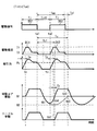
- FIG. 8 is a timing chart showing the behavior of the movable core in the case where irregular injection does not occur because the signal interval is longer than the reference return period
- FIG. 9 is a timing chart showing the behavior of the movable core when irregular injection does not occur because the signal interval is shorter than the allowable period
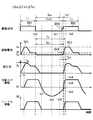
- FIG. 10 is a timing chart showing the behavior of the movable core when irregular injection occurs
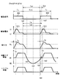
- FIG. 11 is a timing chart showing the behavior of the movable core when irregular injection ceases to occur due to intermediate drive energization
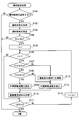
- FIG. 12 is a flowchart showing the procedure of the injection setting process
- FIG. 13 is a timing chart showing how the drive current changes in the second embodiment
- FIG. 14 is a flowchart showing the procedure of the injection setting process
- FIG. 15 is a timing chart showing another variation of drive current
- FIG. 16 is a timing chart showing how the drive current changes in the third embodiment
- FIG. 17 is a timing chart showing the behavior of the movable core when irregular injection ceases to occur due to pre-drive energization
- FIG. 18 is a flowchart showing the procedure of the injection setting process.
- the injector 100 shown in FIG. 1 is included in a combustion system 110.
- the combustion system 110 includes an internal combustion engine 111, an intake pipe 112, and an exhaust pipe 113.
- the internal combustion engine 111 is an ignition engine, for example, a gasoline engine.
- the intake pipe 112 supplies intake air to the combustion chamber 111 a of the internal combustion engine 111, and the exhaust pipe 113 discharges the exhaust gas from the combustion chamber 111 a.
- the internal combustion engine 111 includes a cylinder 114, a piston 115, an intake valve 116, an exhaust valve 117, an injector 100, an ignition plug 122, an intake pressure sensor 123, a crank angle sensor 124 and an ECU 125.
- the piston 115 is provided in the cylinder 114 so as to be capable of reciprocating.
- the combustion chamber 111a is in communication with the intake pipe 112 and the exhaust pipe 113 via the intake port and the exhaust port, the intake valve 116 opens and closes the intake port, and the exhaust valve 117 opens and closes the exhaust port.
- the injector 100 is a fuel injection valve that injects fuel, and directly injects the fuel into the combustion chamber 111a.
- the spark plug 122 ignites the mixture of the intake air and the fuel in the combustion chamber 111a.
- the intake pressure sensor 123 is attached to the intake pipe 112 and detects the pressure in the intake pipe 112 as an intake pressure.
- the crank angle sensor 124 is attached to the crankshaft and detects the crank angle.
- An ECU (Engine Control Unit) 124 is a control device that controls the operation of the combustion system 110.
- the ECU 125 has a computer configured to include a processor 124a, a storage unit 124b, an input / output interface, and the like.
- the storage unit 124 b may be a storage medium such as a RAM.
- a program for performing operation control of the combustion system 110 is stored in the storage unit 124b or the like, and this program is executed by the processor 124a.
- the ECU 125 is electrically connected to various detection units such as the intake pressure sensor 123 and the crank angle sensor 124, and based on the detection results of these detection units, the operation control of the spark plug 122 and the opening degree control of the throttle valve Perform engine control.
- the ECU 125 may refer to the intake pressure sensor 123 or the ECU 125 as an engine control device, and may refer to the combustion system 110 as an engine control system.
- the combustion system 110 includes a fuel supply system 130 for supplying fuel to the combustion chamber 111a.
- the fuel supply system 130 includes a fuel tank 131, a fuel pump 132, a fuel delivery 133, an injection pressure sensor 134, and a control unit 135, in addition to the injector 100 described above.
- the fuel tank 131 stores fuel
- the fuel pump 132 is a high pressure pump that supplies the fuel in the fuel tank 131 to the injector 100 in a state where the fuel pressure is increased.
- the combustion system 110 includes a plurality of injectors 100, and the fuel delivery 133 distributes fuel to the injectors 100.
- the injection pressure sensor 134 is provided in the fuel delivery 133, and detects the pressure of the fuel supplied to the injector 100 as the injection pressure.
- the control unit 135 is a control device that controls the operation of the fuel supply system 130.
- the control unit 135 includes a computer configured to include a processor 135a, a storage unit 135b, an input / output interface, and the like.
- a storage medium such as a RAM may be mentioned.
- a program for controlling the operation of the injector 100 is stored in the storage unit 135b or the like, and this program is executed by the processor 135a.
- the control unit 135 is electrically connected to various detection units such as the injection pressure sensor 134, and performs operation control of the injector 100 and the fuel pump 132 as fuel injection control based on the detection results of these detection units.
- the control unit 135 corresponds to a fuel injection control device that controls the operation of the injector 100 which is a fuel injection valve.
- a sensor control unit SCU
- the injector 100 shown in FIG. 2 includes a housing 20, a nozzle portion 10, a fixed core 60, a movable core 40, a needle 30 as a valve body, a movable plate 50, a first spring 80, a second spring 90, a coil 70 and the like.
- a drive unit for moving the needle 30 includes the movable core 40, the fixed core 60, the coil 70, and the first spring 80.
- the housing 20 includes a first cylindrical member 21, a second cylindrical member 22, a third cylindrical member 23, an outer peripheral member 25, and a resin mold portion 26.
- the first cylindrical member 21, the second cylindrical member 22 and the third cylindrical member 23 are all formed in a substantially cylindrical shape, and are coaxial in the order of the first cylindrical member 21, the second cylindrical member 22 and the third cylindrical member 23. Arranged and connected to each other.
- the outer peripheral member 25 is in contact with the outer peripheral surfaces of the first cylindrical member 21 and the third cylindrical member 23.
- the first cylindrical member 21, the third cylindrical member 23 and the outer peripheral member 25 are made of, for example, a magnetic material such as ferritic stainless steel.
- the second cylindrical member 22 is formed of a nonmagnetic material such as austenitic stainless steel, for example.
- the nozzle portion 10 is provided at an end portion of the first cylindrical member 21 and is formed in a disk shape made of metal. At the center of the nozzle portion 10, an injection hole 11 penetrating the nozzle portion 10 in the plate thickness direction is formed. Further, an annular valve seat 12 is formed on one surface of the nozzle portion 10 so as to surround the injection hole 11. The nozzle portion 10 is connected to the first cylindrical member 21 so that the side wall is fitted to the inner wall of the first cylindrical member 21.
- the fixed core 60 is provided at the end of the third cylindrical member 23, and is formed in a substantially cylindrical shape, for example, by a magnetic material such as ferritic stainless steel.
- the fixed core 60 is provided inside the housing 20.
- the fixed core 60 and the nozzle portion 10 are fixed to the housing 20 by welding.
- the needle 30 is formed in a rod shape, for example, with a metal such as martensitic stainless steel.
- the needle 30 is accommodated in the housing 20 so as to be reciprocally movable in the axial direction.
- the needle 30 is formed at a rod-like main body 32 extending in the axial direction, a seal portion 31 formed at an end of the main body 32 on the nozzle 10 side, and an end of the main body 32 opposite to the nozzle 10 side. And a ridge portion 33.
- the needle 30 opens and closes the injection hole 11 by the seal portion 31 moving away from the valve seat 12 (i.e., leaving) or contacting (i.e., seating) the valve seat 12.
- valve opening direction the direction in which the needle 30 separates from the valve seat 12
- valve closing direction the direction in which the needle 30 abuts on the valve seat 12
- the flange 33 side of the main body 32 is formed in a hollow cylindrical shape, and a hole 34 connecting the inner wall 321 and the outer wall 322 of the main body 32 is formed.
- the collar portion 33 is in the shape of a disc that expands toward the inner wall 24 of the housing 20.
- the movable core 40 is formed in a substantially cylindrical shape, for example, by a magnetic material such as ferritic stainless steel.
- the movable core 40 is accommodated inside the housing 20 so as to be capable of reciprocating between the fixed core 60 and the nozzle unit 10.
- a through hole 44 is formed at the center of the movable core 40.
- the inner wall of the through hole 44 of the movable core 40 and the outer wall 322 of the main body 32 of the needle 30 can slide, and the outer wall 42 of the movable core 40 and the inner wall 24 of the housing 20 can slide.
- the movable core 40 can reciprocate inside the housing 20 while sliding on the needle 30 and the housing 20.
- the movable core 40 has an accommodation recess 45 formed on the end surface 41 on the fixed core 60 side so as to annularly expand radially outward from the inner wall of the through hole 44. Further, the movable core 40 has an insertion groove 46 formed on the end surface 41 on the fixed core 60 side so as to annularly expand radially outward from the end opposite to the bottom wall 452 of the accommodation recess 45.
- the collar 33 of the needle 30 is housed in the housing recess 45, and the movable plate 50, which will be described later, is fitted in the fitting groove 46.
- the movable plate 50 is formed of, for example, a metal such as martensitic stainless steel in a disk shape having a diameter larger than that of the housing recess 45 and has a hole 51 at the center.
- the movable plate 50 is provided on the opposite side of the movable core 40 to the nozzle portion 10 so as to be able to abut on the movable core 40 and the collar portion 33 of the needle 30.
- the movable plate 50 is provided so as to be insertable into the insertion groove 46.
- the coil 70 is formed in a substantially cylindrical shape, and provided so as to surround the radially outer side of the second cylindrical member 22 and the third cylindrical member 23.
- a resin mold portion 26 is filled between the first cylindrical member 21, the second cylindrical member 22, the third cylindrical member 23 and the outer peripheral member 25.
- the first spring 80 contacts the movable plate 50 to apply an elastic force to bias the movable core 40 and the needle 30 in the valve closing direction.
- the second spring 90 abuts on the movable core 40 to apply an elastic force to urge the movable plate 50 toward the fixed core 60 (that is, the valve opening direction).
- the biasing force of the first spring 80 is set larger than the biasing force of the second spring 90. Therefore, in a state where power is not supplied to the coil 70, the needle 30 is in a closed state in which the seal portion 31 abuts on the valve seat 12.
- the first spring 80 corresponds to a valve body biasing portion that biases the valve body
- the second spring 90 corresponds to a core biasing portion that biases the fixed core 60.
- the second spring 90 is provided such that the first end abuts on the bottom surface of the groove 431 formed on the end face 43 on the injection hole 11 side of the movable core 40.
- the second end of the second spring 90 is in contact with an annular step surface 211 formed inside the first cylindrical member 21 of the housing 20.
- the second spring 90 has an axially extending force.
- the second spring 90 biases the movable plate 50 toward the fixed core 60 by biasing the movable core 40.
- the position of the movable core 40 in this case is referred to as an initial position B1.
- the end surface 43 of the movable core 40 is separated from the stepped surface of the first cylindrical member 21 in the axial direction opposite to the injection hole 11. Therefore, the movable core 40 can move to the injection hole 11 side more than the initial position B1.
- the movable plate 50 abuts on both the needle 30 and the movable core 40 by the biasing force of the first spring 80 and the second spring 90. Specifically, the lower end surface 53 of the movable plate 50 abuts on the end surface 331 of the collar 33 of the needle 30 and the bottom wall 461 of the insertion groove 46 of the movable core 40.
- the movable core 40 and the needle 30 in this case are in a closed state.
- the position of the needle 30 in this case is referred to as a valve closing position A1.
- the axial length of the collar 33 is L1
- the axial distance between the lower end surface 53 of the movable plate 50 and the bottom wall 452 of the housing recess 45 is L2.
- the flange 33, the movable plate 50, the housing recess 45, and the fitting groove 46 are formed to satisfy the relationship of L1 ⁇ L2.
- the axial distance between the lower end face 332 of the collar 33 and the bottom wall 452 of the housing recess 45 is G1, and the axial distance between the end face 41 of the movable core 40 and the end face of the fixed core 60 on the movable core 40 side.
- a substantially cylindrical fuel introduction pipe 62 is press-fit and welded to the end of the third cylindrical member 23.
- the fuel flowing from the fuel introduction pipe 62 flows through the fixed core 60, the hole 51 of the movable plate 50, the inside of the main body 32 of the needle 30, the hole 34 of the needle 30, and between the first cylindrical member 21 and the needle 30 in this order. Do. In the state where the needle 30 is opened by energization of the coil 70, the fuel which has flowed as described above is injected from the injection hole 11 after flowing between the seal portion 31 and the valve seat 12.
- the first spring 80 biases the needle 30 in the valve closing direction by biasing the movable plate 50, and the second spring 90 is biased.
- the movable core 40 is biased to the fixed core 60 side.
- the lower end surface 53 of the movable plate 50 abuts on the end surface 331 of the collar 33 of the needle 30 and the bottom wall 461 of the insertion groove 46 of the movable core 40, and L1 ⁇ L2 and G1 ⁇ G2 as described above There is.
- the seal portion 31 of the needle 30 is in the closed state in which the seal portion 31 is seated on the valve seat 12, and the injection hole 11 is in the closed state.
- the movable core 40 When the coil 70 is energized, as shown in FIG. 4, the movable core 40 is attracted to the fixed core 60 and moves to the fixed core 60 side.
- the movable plate 50 is pushed by the movable core 40 and moves toward the first spring 80 against the biasing force of the first spring 80.
- the movable core 40 accelerates by a predetermined distance G1 and collides with the lower end surface 332 of the hook portion 33 of the needle 30 in the state of having kinetic energy of the acceleration distance. Due to the collision, the needle 30 rapidly starts to move in the valve opening direction, the seal portion 31 is separated from the valve seat 12, and the fuel is injected from the injection hole 11.
- the movable core 40 continues to move after colliding with the needle 30, and collides with the fixed core 60 as shown in FIG. That is, the movement of the movable core 40 is restricted.
- the needle 30 is biased in the valve opening direction by the movable core 40 in a state where the collar 33 engages with the bottom wall 452.
- the period in which the movable core 40 collides with the fixed core 60 after the movable core 40 collides with the needle 30 is a period during which the movable core 40 collides with the needle 30.
- the needle 30 leaves the movable core 40 as shown in FIG. 6 and continues moving against the elastic force of the first spring 80 by inertia.
- the first spring 80 pressed against the needle 30 via the movable plate 50 pushes the movable plate 50 and the needle 30 back toward the valve-closing direction to move the spring after the first spring 80 is compressed to the limit.
- the movable plate 50 and the needle 30 thus pushed back stop moving in the state of FIG.
- the overshoot amount L3 is a distance between the needle 30 and the movable core 40 in the axial direction. Specifically, it is the distance in the axial direction from the lower end surface 332 of the collar portion 33 to the bottom wall 452 of the housing recess 45.
- the electromagnetic attraction force decreases, and when the valve opening holding force is reduced, the movable plate 50, the movable core 40 and the needle 30 move in the valve closing direction.
- the movable plate 50 is biased toward the needle 30 by the first spring 80, thereby starting the movement of the movable core in the valve closing direction.
- the movable plate 50 abuts on the hook portion 33 of the needle 30 to bias the needle 30 in the valve closing direction.
- the elastic force of the first spring 80 is transmitted to the needle 30 via the movable plate 50, and the elastic force causes the needle 30 to start the valve closing operation.
- the movement of the needle 30 moving in the valve closing direction is stopped when the seal portion 31 abuts on the valve seat 12.
- the movable core 40 is separated from the movable plate 50 as shown in FIG. 7 and is closed against the elastic force of the second spring 90 by inertia.
- the movable core 40 passes through the initial position B1 and reaches the most separated position B2 by the second spring 90 being contracted, it starts to move in the valve opening direction by the second spring 90 being extended this time. And return to the initial position B1.
- the movable core 40 returned from the most separated position B2 to the initial position B1 stops at the initial position B1 in a state of being caught by the movable plate 50 as shown in FIG. 3.
- the state in which the movable core 40 has moved to the most separated position B2 side from the initial position B1 is referred to as an undershoot.
- a state where the movable core 40 in the undershoot moves toward the valve opening direction from the farthest position B2 to the initial position B1 is referred to as core boost, and the movable core 40 in the core boost restores the second spring 90. It is moving by force.
- the undershoot amount L4 is the axial direction of the movable core 40 and the movable plate 50. It becomes the separation distance in Specifically, the distance is an axial distance between the end surface 41 of the movable core 40 on the stationary core 60 side and the end surface of the movable plate 50 on the stationary core 60 side.
- the undershoot amount L4 is increasing, the movable core 40 is in the process of being moved away from the initial position B1, and the second spring 90 is being contracted by the inertia of the movable core 40.
- the undershoot amount L4 is decreasing, the movable core 40 is in the process of approaching the initial position B1, and the second spring 90 is in the process of being stretched by its own elastic force.
- the movement start timing of the movable plate 50 starts the movement of the movable core 40 regardless of the valve closing and the valve opening. It is the same as the timing.
- the movement start timing of the needle 30 is later than the movement start timing of the movable core 40 in any case of valve closing and valve opening.
- the deviation of the movement start timing between the needle 30 and the movable core 40 is ignored, and the movement of the needle 30 is also started with the movement start of the movable core 40. This is because the first spring 80 directly biases the needle 30 without the movable plate 50 provided, and the hook portion 33 of the needle 30 is caught on the movable core 40 when the movable core 40 is in the initial position. It is possible to realize by the configuration.
- the movable plate 50 is configured separately from the movable core 40 and provides a moving member that moves with the movable core 40.
- the movable plate 50 is pushed and moved by the movable core 40 in the valve opening direction, and is pushed and moved by the first spring 80 in the valve closing direction.
- the movable plate 50 when moved by being pressed by the first spring 80, the movable plate 50 functions as a valve-closing force transmission member that transmits the elastic force of the first spring 80 to the needle 30.
- the control unit 135 causes the injector 100 to perform fuel injection by outputting a drive signal as an electrical signal to the injector 100.
- the coil 70 is energized in accordance with the drive signal.
- a drive current corresponding to the drive signal flows in the coil 70.
- the control unit 135 can perform multiple fuel injections by the injector 100 during one combustion cycle as multi-stage injection.
- the drive signal can also be referred to as a drive command signal or an injection command signal.
- the behavior of the movable core 40 when multistage injection is performed will be described with reference to FIGS. 8 to 11.
- the transition of the drive signal to the high level is referred to as ON
- the transition of the drive signal to the low level is referred to as OFF.
- the first drive signal DS1 is turned off at timing ta1 and is set to timing ta2.
- the second signal C2 is turned on.
- the signal interval Tint is a period from the OFF timing ta1 of the first drive signal DS1 to the ON timing ta2 of the second drive signal DS2. is there.
- a drive instruction period Tj the drive instruction period Tj is different if the first drive signal DS1 and the second drive signal DS2 have the same length. Sometimes it's length.
- the signal interval Tint corresponds to the injection interval.
- a first drive energization DI1 through which a drive current according to a first drive signal DS1 flows, and a second drive energization DI2 through which a drive current according to a second drive signal DS2 flows There is.
- the drive current associated with the drive energization DI1 and DI2 gradually increases to the first drive value Ia with the ON of the drive signals DS1 and DS2, and is maintained at this first drive value Ia for a certain period.
- the drive signals DS1 and DS2 include information for changing the drive current associated with the drive energization DI1 and DI2 to the first drive value Ia and the second drive value Ib. Further, the first drive energization DI1 corresponds to the first energization, and the second drive energization DI2 corresponds to the second energization.
- the electromagnetic attraction generated by the drive energization DI1, DI2 gradually rises up to the movable value Pc by gradually increasing with the increase of the drive energization DI1, DI2, and the movable core 40 is opened by the electromagnetic attraction reaching the movable value Pc. Start moving in the direction. As a result, the needle 30 is opened to start fuel injection.
- the movable value Pc is, for example, a value capable of overcoming the biasing force of the first spring 80.
- the timing when the electromagnetic attraction force reaches the movable value Pc is referred to as rising timing tc, and the period required for the electromagnetic attraction force to reach the movable value Pc from the timing when the drive signals DS1 and DS2 are turned ON is referred to as a rising period To.
- the period from the ON timing ta2 to the rising timing tc corresponds to the rising period To.
- the drive signals DS1 and DS2 and the drive energization DI1 and DI2 are set such that the rising periods To of the drive signals DS1 and DS2 are the same.
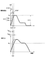
- the vertical axis represents the amount of movement of the movable core 40 and the needle 30, and an increase in the amount of movement indicates a movement in the valve opening direction. Indicates the movement toward the valve closing direction.
- the movable core 40 and the needle 30 start to move in the valve closing direction accordingly, and the undershoot of the movable core 40 occurs as described above.
- the movable core 40 that undershoots passes through the initial position B1 in the valve closing direction at timing tb1, and reaches the most separated position B2 at timing tb2. Thereafter, the movable core 40 returns to the initial position B1 at timing tb3 by moving in the valve opening direction.
- the timing tb3 is referred to as a reference return timing tb3, and the period from the OFF timing ta1 of the first drive signal DS1 to the reference return timing tb3 is referred to as a reference return period Tu. Further, the timing tb2 at which the movable core 40 reaches the most separated position B2 is referred to as the most separated timing tb2. Furthermore, when timing tb1 at which the undershoot of the movable core 40 starts is referred to as start timing tb1, a period from the start timing tb1 to the reference return timing tb3 corresponds to an undershoot period in which the movable core 40 undershoots.
- the electromagnetic attraction force is not applied to the movable core 40 in the undershoot.
- the reference return timing tb3 is earlier than the ON timing ta2 of the second drive signal DS2
- the signal interval Tint is longer than the reference return period Tu.
- the reference return period Tu includes a specific period To1 having the same length as the rising period To.
- the specific period To1 is a period between the specific timing tb5 and the reference return timing tb3.
- the reference return period Tu includes an allowable period Tuo having a length obtained by subtracting the specific period To1 from the reference return period Tu.
- the allowable period Tuo is a period between the OFF timing ta1 of the first drive signal DS1 and the specific timing tb5, and is shorter than the reference return period Tu.
- the reference return timing tb3 and the reference return period Tu by storing past information and experimental information in the storage unit 135b. Also, it is possible to predict the rising period To of the electromagnetic attraction force due to the second drive energization DI2.
- the reference return timing tb3 can also be referred to as a predicted return timing
- the reference return period Tu and the rising period To can also be referred to as a predicted return period and a predicted rising period.
- the movable core 40 in the undershoot in the predicted allowable period Tuo is electromagnetically Suction is applied.
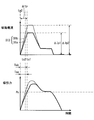
- the signal interval Tint is shorter than the reference return period Tu.
- the signal interval Tint is shorter than the permissible period Tuo.
- the movable core 40 is forcibly pulled back to the initial position B1 side in the allowable period Tuo, so that the undershoot period is shortened.
- the timing at which the movable core 40 returns to the initial position B1 is the core return timing tb4 earlier than the reference return timing tb3.
- the period required for the movable core 40 to return to the initial position B1 from the OFF timing ta1 of the first drive signal DS1 is the core return period Tu1 shorter than the reference return period Tu.
- the core return period Tu1 corresponds to the additional return period
- the core return timing tb4 corresponds to the additional return timing.
- the movable core 40 is not returned to the initial position B1 by the rise timing tc, and the core return timing tb4 is later than the rise timing tc.
- the electromagnetic attraction force increases to at least the movable value Pc.
- the movable core 40 collides with the needle 30 by returning to the initial position B1, and moves the needle 30 together with the needle 30 through the initial position B1 by the electromagnetic attraction force equal to or more than the movable value Pc. Open 30.
- the movable core 40 starts moving from the initial position B1 in the valve opening direction with a delay of the core delay period Tz. Therefore, if the drive command period Tj is constant, the fuel injection amount from the injection hole 11 is reduced by the core delay period Tz as compared with the case where the core delay period Tz is zero.
- the movable core during undershooting is performed as in the case where the reference return timing tb3 is included in the rising period To.
- a magnetic attraction is applied to 40.
- the signal interval Tint is less than or equal to the reference return period Tu because the reference return timing tb3 is later than the ON timing ta2 of the second drive signal DS2.
- the signal interval Tint is equal to or longer than the allowable period Tuo.
- the movable core 40 when the reference return timing tb3 is included in the rising period To, the movable core 40 is forcibly pulled back to the initial position B1 in the specific period To1, so that the undershoot period is shortened. In this case, as in the case where the reference return timing tb3 is later than the rising period To (see FIG. 9), the movable core 40 returns to the initial position B1 at a core return timing tb4 earlier than the reference return timing tb3. As a result, the core return period Tu1 becomes shorter than the reference return period Tu.
- the reason why the undershoot period is shortened in the specific period To1 is that the movable core 40 accelerates due to the electromagnetic attraction force being further applied to the movable core 40 in the core boost.
- the electromagnetic attraction force applied to the movable core 40 in the specific period To1 has not yet reached the movable value Pc, and if the movable core 40 is stopped at the initial position B1, movement can not be started. It is a relatively small force.
- the accelerated movable core 40 temporarily returns to the initial position B1 and collides with the needle 30 so that the needle 30 temporarily passes through the initial position B1 and moves toward the valve-opening side, but the impact force due to the collision By damping, it moves to the valve closing side again and returns to the initial position B1.
- the temporary movement of the movable core 40 toward the valve-opening side from the initial position B1 is referred to as an irregular movement.
- the needle 30 is also temporarily opened. Actuation causes irregular injection in which fuel is unintentionally injected.
- the reference return timing tb3 is included in the rising period To, the inventor of the present invention performs the irregular movement of the movable core 40 or the fuel between the fuel injection by the first drive signal DS1 and the fuel injection by the second drive signal DS2. We found that irregular injection is likely to occur.
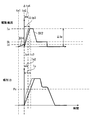
- an intermediate drive signal DS3 as a drive signal is output from the control unit 135 in the allowable period Tuo.
- the intermediate drive signal DS3 is turned on at timing td1 in the signal interval Tint and turned off at timing td2.
- this intermediate command period Tk is between the undershoot start timing tb1 and the most separate timing tb2.
- the intermediate drive signal DS3 is turned on after the start of the undershoot of the movable core 40, and the intermediate drive signal DS3 is turned off before the movable core 40 reaches the most separated position B2.
- a current due to the intermediate drive energization DI3 according to the intermediate drive signal DS3 flows.
- the current due to the intermediate drive energization DI3 gradually increases to the third drive value Ic with the turning on of the intermediate drive signal DS3, and gradually decreases to zero after reaching the third drive value Ic.
- the third drive value Ic is a value between the first drive value Ia and the second drive value Ib.
- the intermediate drive signal DS3 includes information for changing the drive current associated with the intermediate drive energization DI3 to the third drive value Ic.
- the intermediate drive energization DI3 corresponds to additional energization, and may be held for a certain period of time at the third drive value Ic, and may be reduced as soon as the third drive value Ic is reached.
- the electromagnetic attraction force generated by the intermediate drive energization DI3 gradually increases with the increase of the intermediate drive energization DI3, and gradually decreases with the decrease of the intermediate drive energization DI3.
- This electromagnetic attraction does not reach the movable value Pc, unlike the electromagnetic attraction caused by the drive energization DI1 and DI2.
- the movable core 40 is forcibly pulled back to the initial position B1, the undershoot period is Becomes shorter.
- the movable core 40 returns to the initial position B1 at the core return timing tb4 earlier than the reference return timing tb3 and the core return period Tu1 is a reference It is shorter than the return period Tu.
- the intermediate command period Tk and the third drive value Ic are set such that the core return timing tb4 is earlier than the specific period To1.
- the electromagnetic attraction force is not applied to the movable core 40 in the undershoot. . Therefore, the occurrence of the irregular movement of the movable core 40 due to the electromagnetic attraction is suppressed.
- the core return timing tb4 is included in the allowable period Tuo, and the core return period Tu1 is shorter than the allowable period Tuo.
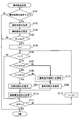
- the control unit 135 performs an injection setting process to set an injection mode when the fuel is injected from the injector 100. This process will be described with reference to the flowchart of FIG.
- the control unit 135 performs fuel injection control for the injector 100 by performing operation control of the injector 100 according to the injection mode set in the injection setting process.
- the flowchart of FIG. 12 also shows a fuel injection control method.
- step S101 it is determined whether the fuel injection mode is set for one combustion cycle.
- the process proceeds to step S102, and the operating state of the internal combustion engine 111 is acquired.
- intake pressure detected using the detection signal of the intake pressure sensor 123, engine rotational speed detected using the detection signal of the crank angle sensor 124, etc. are acquired as information indicating the operating state of the internal combustion engine 111. Do.
- step S103 the fuel injection mode is set. Then, information on the injection mode is stored in the storage unit 135b.
- the injection mode the injection amount Q, the drive command period Tj, the injection start timing SOI, the injection end timing EOI, the injection pressure Pf, and the number of injections Ninj are set.
- the injection amount Q is the total amount of fuel injected in one combustion cycle
- the drive command period Tj is a period during which the drive signal is ON as described above.
- the injection start timing SOI is the timing to start the first fuel injection in one combustion cycle
- the injection end timing EOI is the timing to end the last fuel injection in one combustion cycle.
- the injection pressure Pf is the pressure of fuel injected from the injector 100
- the number of injections Ninj is the number of times of fuel injection in one combustion cycle.
- the injection mode when the number of times of injection Ninj is a plurality of times, the above-described signal interval Tint and the drive command period Tj are set. In addition, drive values Ia and Ib of the drive current are also set.
- step S104 it is determined whether the number of injections Ninj is a plurality of times. When the number of times of injection Ninj is one, the main injection setting process ends. If the number of injections Ninj is a plurality of times, the process proceeds to step S105 as multistage injection, and if the number of injections Ninj is one, the present injection setting processing is ended as it is. In step S105, the counter i is set to "1" in order to individually recognize a plurality of fuel injections.
- steps S106 to S114 an update process is performed to update the setting content regarding the drive current for each of the plurality of fuel injections in the multistage injection.
- the setting content of the drive current for the i-th fuel injection is updated for the counter i. That is, the injection setting for the i-th shot is performed.
- step S106 it is determined whether the counter i is larger than "1". If the counter i is not larger than "1”, the process proceeds to step S111, assuming that the update process is not performed for the first fuel injection in the multistage injection. This means that the setting content of the drive current already set in step S103 is adopted for the first fuel injection.
- step S111 it is determined whether the counter i has reached the number of injections Ninj. If the counter i has reached the number of injections Ninj, it is assumed that the update process has been performed for all of the plurality of fuel injections in the multistage injection, and the present injection setting process is ended. If the counter i has not reached the number of injections Ninj, the process proceeds to step S113, and the counter i is incremented by one. Thereafter, the process returns to step S106. Here, the processing of steps S106 to S113 is repeated until the counter i reaches the number of injections Ninj.
- step S107 it is determined whether the signal interval Tint is greater than or equal to the allowable period Tuo.
- energization for fuel injection targeted in the previous processing is set as a first drive energization DI1
- current for fuel injection targeted in the present processing is set as a second drive energization DI2.
- the drive values Ia and Ib, the drive command period Tj, the signal interval Tint, and the rise period To are obtained as parameters for the drive energization DI1 and DI2, and the tolerance period Tuo is calculated as a predicted value using these parameters.
- the rising period To due to the second drive energization DI2 is also acquired as a predicted value.
- step S108 the reference return period Tu is calculated as a predicted value using the same parameters as step S107, and it is determined whether the signal interval Tint is less than or equal to the reference return period Tu.
- the determinations in steps S107 and S108 are both positive, as shown in FIG. 10, it is assumed that Tuo ⁇ Tint ⁇ Tu, which is a condition that irregular injection tends to occur, and the process proceeds to step S109.
- steps S107 and S108 also determine whether or not the reference return timing tb3 is included in the rising period To due to the second drive energization DI2. Therefore, when the reference return timing tb3 is included in the rising period To, the process proceeds to step S109.
- step S109 an intermediate drive energization DI3 is added between the first drive energization DI1 and the second drive energization DI2.
- the timing of the intermediate drive energization DI3, the energization period, the third drive value Ic, and the like are set such that the core return timing tb4 is earlier than the specific period To1. That is, the waveform of the drive current accompanying the intermediate drive energization DI3 is set.
- the ON timing td1, the OFF timing td2, the intermediate command period Tk, and the like are also set for the intermediate drive signal DS3 so as to realize the waveform of the drive current.
- step S110 information relating to the drive current such as the waveform of the drive current accompanying the second drive energization DI2 and the waveform of the drive current accompanying the intermediate drive energization DI3 is stored in the storage unit 135b in association with the i-th fuel injection.
- step S107 If it is determined in step S107 that the signal interval Tint is not longer than the allowable period Tuo, as shown in FIG. 9, it is determined that Tint ⁇ Tuo, which is a condition under which irregular injection is less likely to occur, and the process proceeds to step S112.
- Tint ⁇ Tuo is satisfied, as described above, the time for the second drive energization DI2 to flow through the coil 70 is shortened by the amount of the core delay period Tz, and the fuel injection amount by the second drive energization DI2 is intended. May decrease without Therefore, in step S112, the drive command period Tj of the second drive signal DS2 is updated to correct the power supply period of the second drive power supply DI2.
- the drive command period Tj is set such that the period in which the second drive energization DI2 flows through the coil 70 becomes longer by the core delay period Tz.
- the control unit 135 has a function of executing the process of each step in the injection setting process.
- the function of executing the process of step S109 corresponds to the additional energizing unit.
- the intermediate drive energization DI3 is performed.
- the core return timing tb4 at which the movable core 40 actually returns to the initial position can be advanced earlier than the specific timing tb5.
- the signal interval Tint is longer than the core return period Tu1
- the condition for the occurrence of the irregular injection that the signal interval Tint is not less than the allowable period Tuo and not more than the reference return period Tu is that the reference return timing tb3 by the first drive energization DI1 is the rise period To in the second drive energization DI2. It is also included. Therefore, performing the intermediate drive energization DI3 causes the core return timing tb4 to be earlier than the rising period To of the second drive energization DI2. As described above, even from the viewpoint of whether or not the core return timing tb4 is earlier than the rising period To, performing the intermediate drive energization DI3 avoids the occurrence condition of the irregular injection.
- the intermediate drive energization DI3 when the signal interval Tint is longer than the reference return period Tu, the intermediate drive energization DI3 is not performed.
- the reference return period Tu is shortened to the core return period Tu1, which may result in the occurrence condition of the irregular injection being satisfied. is there. That is, there is a possibility that the condition that the signal interval Tint is equal to or more than the allowable period Tuo and equal to or less than the core return period Tu1 may be met.
- the intermediate drive energization DI3 is inhibited, and the movable core 40 is accelerated by the electromagnetic attraction force, which corresponds to the condition for generating the irregular injection. That can be reliably avoided.
- the content of the intermediate drive energization DI3 is set such that the core return timing tb4 is earlier than the specific period To1. Therefore, it is possible to avoid the situation where the signal interval Tint is not shorter than the allowable period Tuo despite the addition of the intermediate drive energization DI3. This makes it possible to more reliably suppress the occurrence of irregular injection.
- the core return timing tb4 is earlier than the specific period To1 means that the core return timing tb4 is earlier than the rising period To associated with the second drive energization DI2.
- the core return timing tb4 is earlier than the rising period To, it is possible to perform the intermediate drive energization DI3 so that the core return timing tb4 is earlier than the rising period To. It will avoid the occurrence condition.
- the electromagnetic attraction force is applied to the movable core 40 while the needle 30 is in the valve closing operation. It can be avoided.
- the electromagnetic attraction is applied to the movable core 40 at a timing earlier than the undershoot start timing tb1
- the movement of the movable core 40 which is about to return to the initial position B1 in accordance with the valve closing operation of the needle 30 is There is a possibility that it may be disturbed by electromagnetic attraction.
- the intermediate drive energization DI3 is performed at a timing that does not disturb the valve closing operation of the needle 30. Therefore, it is possible to appropriately suppress the valve closing operation of the needle 30 by the first drive energization DI1, and to suppress the occurrence of the irregular injection of the fuel by the second drive energization DI2.
- the control unit 135 can select the normal energization DIa not shortening the rising period To and the shortened energization DIb shortening the rising period To.
- the shortening gradient Sb which is the current gradient for the shortening energization DIb, corresponds to that for the normal energization DIa.
- the current gradient is larger than the normal gradient Sa.
- the current gradient is a ratio of a change amount ⁇ Ip until the drive current reaches the maximum value with respect to a required period ⁇ tp required for the drive current to reach the maximum value.
- the amount of change ⁇ Ip is the same for the normal energization DIa and the shortening energization DIb, and the required period ⁇ tp is shorter in the shortening energization DIb than in the normal energization DIa.
- the required period ⁇ tp of the normal energization DIa is called a normal required period ⁇ tp1 and the required period ⁇ tp of the shortened energization DIb is called a shortened required period ⁇ tp2
- the shortened required period ⁇ tp2 is shorter than the normal required period ⁇ tp1.
- the relationship of ⁇ Ip / ⁇ tp2> ⁇ Ip / ⁇ tp1 holds.
- the maximum value of the drive current is the first drive value Ia
- the amount of change ⁇ Ip is the same value as the first drive value Ia for both the normal energization DIa and the shortened energization DIb.
- the electromagnetic attraction force reaches the movable value Pc at the normal rise timing tc1, and the period required for the arrival is referred to as the normal rise period Toa.
- the electromagnetic attractive force normally reaches the movable value Pc at the shortening rising timing tc2 earlier than the rising timing tc1, and the period required for the reaching is referred to as a shortening rising period Tob.
- the shortened rising period Tob is shorter than the normal rising period Toa.
- the control unit 135 selects the normal conduction DIa and the short conduction DIb by selecting the voltage applied to the coil 70. Information on the voltage applied to the coil 70 is included in the drive signal.
- the normal energization DIa corresponds to the occurrence condition of irregular injection Tuo ⁇ Tint ⁇ Tu because the normal rising period Toa includes the reference return timing tb3.
- the reduced energization DIb does not fall under the irregular injection condition of Tuo ⁇ Tint ⁇ Tu because the reduced rising period Tob does not include the reference return timing tb3. For this reason, when the rising period To is shortened by selecting not the normal conduction DIa but the short conduction DIb as the second drive conduction DI2, it is possible to avoid the occurrence condition of irregular injection Tuo ⁇ Tint ⁇ Tu. become.
- the control unit 135 basically executes the same injection setting process as the first embodiment. However, in the present embodiment, steps S201 and S202 are executed instead of steps S109 and S113 in the first embodiment.
- step S201 the shortening gradient Sb is set by selecting the shortening energization DIb as the second driving energization DI2. That is, the waveform of the drive current associated with the second drive energization DI2 is set.
- setting the shortening gradient Sb instead of the normal gradient Sa can reduce the possibility that the reference return timing tb3 is included in the shortening rising period Tob.
- the function of executing the process of step S201 corresponds to the change energizing unit.
- step S202 the normal gradient Sa is set by selecting the normal energization DIa as the second drive energization DI2.
- the normal gradient Sa is set by selecting the normal energization DIa as the second drive energization DI2.
- step S110 the process proceeds to step S110, and this time, as information on the waveform of the drive current accompanying the second drive energization DI2, the normal gradient Sa etc. of the drive current accompanying the normal energization DIa is made to correspond to the i-th fuel injection Storage unit 135b.
- the shortened rising period Tob when the shortened energization DIb is selected as the second drive current DI2 is shorter than the normal rising period Toa. That is, the current gradient by the second drive energization DI2 becomes larger than the current gradient by the first drive energization DI1. Therefore, the probability that the reference return timing tb3 is included in the reduced rising period Tob can be reduced. Further, if the shortening rising period Tob is selected and the rising period To is shortened, the allowable period Tuo becomes long, so it becomes easy to avoid the condition of irregular injection where the signal interval Tint is equal to or longer than the allowable period Tuo. In addition, when the occurrence condition of the irregular injection is not met, the normal energization DIa is selected as the second drive energization DI2, so energy saving can be achieved.
- the shortening gradient Sb is larger than the normal gradient Sa
- the increasing rate of the electromagnetic attraction generated by the reduced energization DIb is larger than the increasing rate of the electromagnetic attraction generated by the normal energization DIa.
- the electromagnetic attraction force which sharply increases before and after the reference return timing tb3 is movable against the biasing force of the first spring 80. It becomes possible to move the core 40 in the valve opening direction. Therefore, after the movable core 40 in the core boost passes the initial position B1 in the valve opening direction, the movable core 40 moves again in the valve closing direction by the biasing force of the first spring 80 and returns to the initial position B1. Irregular movement is less likely to occur. That is, irregular injection of fuel can be suppressed.
- the required period ⁇ tp is the same for the normal energization DIa and the shortening energization DIb, and the change amount ⁇ Ip is smaller for the shortening energization DIb.
- the normal change amount ⁇ Ip when change amount ⁇ Ip of normal energization DIa is referred to as normal change amount ⁇ Ip1, and change amount ⁇ Ip of shortening energization DIb is referred to as short change amount ⁇ Ip2, shortening change amount ⁇ Ip2 is larger than normal change amount ⁇ Ip1.
- the shortening energization DIb is the second drive energization DI2 as the second drive energization DI2, it is possible to avoid the generation condition of the irregular injection.
- the first drive value of the normal conduction DIa is the normal change amount ⁇ Ip1
- the first drive value of the short conduction DIb is the shortening change amount ⁇ Ip2.
- the required period ⁇ tp and the change amount ⁇ Ip may be different between the normal energization DIa and the shortening energization DIb.
- the intermediate drive energization DI3 is added to avoid the irregular injection generation condition.
- the pre-drive energization DI4 is started at the pre-timing te1 before starting the second drive energization DI2, and the second drive energization DI2 is continuous without interrupting the pre-drive energization DI4.
- the pre-drive energization DI4 and the second drive energization DI2 are switched at the ON timing ta2 of the second drive signal DS2.
- the pre-drive energization DI4 When the pre-drive energization DI4 is not performed because the drive current has already reached the fourth drive value Id at the ON timing ta2 of the second drive signal DS2 when the pre-drive energization DI4 is performed.
- the drive current reaches the first drive value Ia at an earlier timing than in the comparison.
- the pre no-pass slope Sc in the case where the pre-drive energization DI4 is not performed corresponds to the pre no required period ⁇ tp3 with respect to the change amount ⁇ Ip. It is a ratio.
- the pre-presence slope Sd when the pre-drive energization DI4 is performed is a ratio of the pre-prescription required period ⁇ tp4 to the change amount ⁇ Ip, and is larger than the pre-presence slope Sc. That is, the pre-prerequisite period required ⁇ tp4 is shorter than the non-pre-requisite period ⁇ tp3.
- the electromagnetic attraction force When there is no pre-drive energization DI4, the electromagnetic attraction force reaches the movable value Pc at timing tc3, and when there is the pre-drive energization DI4, the electromagnetic attraction force is movable at timing tc4 earlier than timing tc3. Reach Pc. Therefore, the pre-rising period To2 required for the electromagnetic attraction force to reach the movable value Pc when there is the pre-drive energization DI4 is shorter than the rising period To when the pre-drive energization DI4 is not present. In the case where there is the pre-drive energization DI4, the rate of increase of both the drive current and the electromagnetic attractive force immediately after the second drive signal DS2 is turned on is particularly large, and thereafter, each rate of increase slightly decreases.
- the pre-drive for performing the pre-drive energization DI4 The signal DS4 is turned on.
- the pre-drive signal DS4 is turned ON in a period between the specific timing tb5 and the ON timing ta2 of the second drive signal DS2, and is in a state of being handed over to the second drive signal DS2 without being turned OFF.
- the pre-drive signal DS4 includes information on the maximum value of the drive current and the like associated with the pre-drive energization DI4.
- the pre-drive energization DI4 is performed, whereby the rising period To of the second drive energization DI2 is pre-run. It is shortened to the rising period To2.
- the increasing rate of the electromagnetic attraction force becomes large, so even if the core return timing tb4 is included in the pre-rising period To2, the electromagnetic attraction force sharply increases before and after the core return timing tb4. Irregular movement of the movable core 40 is less likely to occur.
- the electromagnetic attraction force resists the first spring 80, whereby the movable core 40 is moved to the initial position B1. Continue moving in the valve opening direction without returning.
- the control unit 135 basically executes the same injection setting process as the first embodiment. However, in the present embodiment, steps S301 and S302 are executed in place of steps S109 and S113 in the first embodiment.
- step S301 a pre-drive energization DI4 is added before the second drive energization DI2.
- the pre-timing of the pre-drive energization DI4, the fourth drive value Id, and the like are set so that the electromagnetic attraction force is not generated at a timing earlier than the ON timing ta2 of the second drive signal DS2. That is, the waveform of the drive current accompanying the pre-drive energization DI4 is set.
- the function of executing the process of step S301 corresponds to the pre-energization unit.
- step S302 When it does not correspond to Tuo ⁇ Tint ⁇ Tu which is a generation condition of the irregular injection, the process proceeds to step S302, and the setting of the pre-drive energization DI4 is prohibited.
- the pre-drive energization DI4 is added, power consumption is increased as compared with the case where the pre-drive energization DI4 is not added. For this reason, energy saving can be realized by prohibiting the setting of the pre-drive energization DI4.
- step S302 the process proceeds to step S110, and the pre no gradient Sc or the like is stored in the storage unit 135b in association with the i-th fuel injection as information on the waveform of the drive current accompanying the second drive energization DI2.
- the increase rate of the electromagnetic attraction force by the second drive energization DI2 becomes high, so that the movable core 40 is moved irregularly. It becomes difficult. Further, in this case, since the rising period To is shortened to the pre rising period To2 by the addition of the pre-drive energization DI4, the probability that the core return timing tb4 is included in the pre rising period To2 can be reduced. By these things, the irregular injection of a fuel can be suppressed.
- the reference return period Tu and the allowance period Tuo may not be started from the OFF timing ta1 of the first drive signal DS1.
- the reference return period Tu and the allowance period Tuo are configured to start from an undershoot start timing tb1 or a timing when the drive current associated with the first drive signal DS1 becomes zero. The point is that the reference return period Tu and the allowance period Tuo may be coincident with each other at timings earlier than the specific timing tb5.
- the rising period To of the electromagnetic attraction force may be different between the first drive energization DI1 and the second drive energization DI2.
- the reference return timing tb3 and the core return timing tb4 are included in the rising period To of the electromagnetic attraction force by the second drive energization DI2, so that the condition of occurrence of irregular injection Tuo ⁇ Tint ⁇ Tu is satisfied. become.
- the configuration in which the movable core 40 in the undershoot core boosts to the initial position B1 is realized by the restoring force when the second spring 90 extends. It may be realized by the restoring force when the spring 90 is contracted. Further, the second spring 90 may not be provided. Even in this case, for example, when the movable core 40 strikes the step surface 211 or the like of the housing 20 and bounces back, it is possible to realize a configuration in which core boosting is performed toward the initial position B1.
- the third drive value Ic due to the intermediate drive energization DI3 is set to a value smaller than the first drive value Ia and larger than the second drive value Ib. May be larger than the first drive value Ia or smaller than the second drive value Ib.
- the third drive value Ic may be a value that can avoid the irregular injection generation condition Tuo ⁇ Tint ⁇ Tu by the addition of the intermediate drive energization DI3.
- the maximum value of the electromagnetic attraction force by the intermediate drive energization DI3 is a value smaller than the movable value Pc, but may be a value larger than the movable value Pc. Even in this case, the maximum value of the electromagnetic attraction force by the intermediate drive energization DI3 may be set so as to avoid the irregular injection generation condition of Tuo ⁇ Tint ⁇ Tu.
- the intermediate command period Tk of the intermediate drive energization DI3 ends at a timing earlier than the maximum separation timing tb2, but the intermediate command period Tk is disposed after the maximum separation timing tb2. It may be Even in this case, the timing and the length of the intermediate command period Tk may be set so that the occurrence condition of the irregular injection Tuo ⁇ Tint ⁇ Tu can be avoided by the addition of the intermediate drive energization DI3.
- the intermediate drive energization DI3 may be added even when the irregular injection occurrence condition is not met. For example, when the signal interval Tint is longer than the reference return period Tu, or when the signal interval Tint is shorter than the allowable period Tuo, the intermediate drive energization DI3 is added between the first drive energization DI1 and the second drive energization DI2.
- the current gradient due to the second drive energization DI2 is larger than the current gradient due to the first drive energization DI1 when falling under the condition of occurrence of irregular injection Tu0 ⁇ Tint ⁇ Tu.
- the current gradient due to the next drive current conduction is configured to be larger than the current gradient due to the current drive current conduction.
- the drive current for fuel injection is repeatedly performed, whereby the current gradient is gradually increased. Therefore, as the number of times of drive current for fuel injection increases, generation of irregular injection is more reliably suppressed. it can.
- the fourth drive value Id by the pre-drive energization DI4 is set to a value smaller than the second drive value Ib, but the fourth drive value Id is a second drive value Ib. It may be larger.
- the fourth drive value Id may be larger than the first drive value Ia or the third drive value Ic.
- the pre-timing te1 at which the pre-drive energization DI4 is started may be earlier than the specific timing tb5.
- the fourth drive value Id is set to an appropriate value, or the like, so that the electromagnetic attraction force does not become too large at a timing earlier than the start timing tb1 of the second drive signal DS2. It is preferable to set.
- the control unit 135 performs the injection setting process in each of the above-described embodiments as the eleventh modification
- the ECU 125 may perform the injection setting process.
- the ECU 125 corresponds to a fuel injection control device.
- part of the function for executing the injection setting process may be included in the control unit 135, and the remaining function may be included in the ECU 125.
- the control unit 135 and the ECU 125 cooperate as a plurality of arithmetic devices to exhibit the function as a fuel injection control device.
- various programs may be stored in a non-transitional tangible storage medium such as a flash memory or a hard disk provided in each arithmetic device.
- the ECU 125 and the control unit 135 may be configured to include a dedicated electric circuit having at least one integrated circuit and a passive element.
- the additional energizing unit which is a function of executing the process of step S109, for example, is configured by at least one dedicated electric circuit unit.
Abstract
燃料噴射制御装置は、燃料噴射のための第1通電(DI1)により発生するアンダーシュートについて、第1通電から可動コア(40)が初期位置(B1)に戻ってくるまでに要すると予測される期間を戻り期間(Tu)と称し、第1通電から次の燃料噴射のための第2通電(DI2)までの期間を噴射インターバル(Tint)と称し、第2通電について予測される立ち上がり期間(To)を戻り期間から引いた値を許容期間(Tuo)と称すると、噴射インターバルが許容期間以上であり且つ戻り期間以下である場合に、第1通電と第2通電との間に追加通電(DI3)を追加する追加通電部(S109)、を備える。
Description
本出願は、2017年7月28日に出願された日本特許出願番号2017-146905号に基づくもので、ここにその記載内容を援用する。
この明細書による開示は、燃料噴射制御装置及び燃料噴射制御方法に関する。
燃料を噴射する燃料噴射弁として、コイルへの通電に伴って発生する電磁吸引力により移動する可動コアと、可動コアの移動に伴って開弁作動する弁体とを備え、可動コアと弁体との相対的な移動が可能になっている燃料噴射弁がある。例えば、特許文献1には、噴孔を閉鎖する閉弁向きに移動する弁体が閉弁位置にて停止しても、可動コアは、弁体の閉弁位置に対応した初期位置に停止せずに、弁体に対する相対移動として閉弁向きへの移動を継続する、という構成が開示されている。
ここで、弁体が閉弁位置で停止したにもかかわらず可動コアが初期位置よりも閉弁側にある状態をアンダーシュートと称すると、コイルへの次の通電に伴って発生した電磁吸引力によりアンダーシュート中の可動コイルが吸引されることがある。この場合、アンダーシュート中の可動コイルが電磁吸引力により開弁向きに強制的に引き戻されることで、この可動コアが初期位置で停止せずに開弁側に通過することが考えられる。
本発明者は、アンダーシュート中の可動コアに電磁吸引力が加えられるタイミングや電磁吸引力の大きさによっては、可動コアが初期位置を開弁側に通過してもすぐに移動向きが閉弁向きに変わって初期位置に戻ってしまうことがある、という知見を得た。このように、可動コアが初期位置よりも開弁側に意図せずに一時的に移動すると、燃料が意図せずに一時的に噴射される不整噴射が発生するおそれがある。
本開示の目的は、燃料が意図せずに一時的に噴射される不整噴射の発生を抑制できる燃料噴射制御装置及び燃料噴射制御方法を提供することにある。
本開示の第1態様による燃料噴射制御装置は、燃料を噴射する噴孔と、開弁向きに移動することで噴孔を開放する弁体と、コイルへの通電に伴い電磁吸引力を生じさせる固定コアと、弁体に対して相対的な移動が可能であり、所定の初期位置から固定コアに吸引されて開弁向きに移動することで弁体を開弁向きに移動させる可動コアと、弁体を開弁向きとは反対向きの閉弁向きに付勢する弁体付勢部と、を備え、可動コアは、通電に伴う電磁吸引力の立ち上がりに要する立ち上がり期間が経過することで開弁向きに移動を開始し、弁体は、弁体付勢部の付勢力により閉弁向きに移動することで可動コアを閉弁向きに移動させ、閉弁向きに移動する弁体が停止しても可動コアが閉弁向きへの移動を継続するアンダーシュートにおいて、可動コアが移動向きを開弁向きに変えて初期位置に戻る燃料噴射弁、に適用される燃料噴射制御装置であって、燃料噴射のための第1通電により発生するアンダーシュートについて、第1通電から可動コアが初期位置に戻ってくるまでに要すると予測される期間を戻り期間と称し、第1通電から次の燃料噴射のための第2通電までの期間を噴射インターバルと称し、第2通電について予測される立ち上がり期間を戻り期間から引いた値を許容期間と称すると、噴射インターバルが許容期間以上であり且つ戻り期間以下である場合に、第1通電と第2通電との間に追加通電を追加する追加通電部、を備える。
燃料噴射弁においては、可動コアが初期位置に停止している状態で電磁吸引力が生じても、電磁吸引力の大きさが不足している場合には開弁向きへの可動コアの移動が開始しないと考えられる。これに対して、本発明者は、噴射インターバルが許容期間以上であり且つ戻り期間以下である場合に、アンダーシュート中の可動コアが電磁吸引力により加速されて燃料の不整噴射が発生しやすい、という知見を得た。この知見によれば、アンダーシュートにおいてコアブーストで開弁向きに移動している可動コアに電磁吸引力が加えられると、この電磁吸引力が十分に立ち上がっていなくてもコアブースト中の可動コアが加速される。このように加速された可動コアが初期位置に到達すると、可動コアの勢いで弁体がこの可動コアと共に開弁向きに意図せずに移動する、ということが生じやすくなる。その一方で、初期位置よりも開弁側に移動した可動コアは、十分に立ち上がっていない電磁吸引力が弁体付勢部の付勢力に負けることで移動向きを閉弁向きに変えて初期位置に戻り、これに伴って弁体も閉弁する。このようにして燃料の不整噴射が発生すると考えられる。
そこで、上記第1態様によれば、噴射インターバルが許容期間以上である且つ戻り期間以下である場合に、第1通電と第2通電との間で追加通電が行われる。この場合、可動コアが電磁吸引力により加速されることで実際の戻り期間が短縮されるため、実際の戻り期間を噴射インターバルより短くすることが可能になる。すなわち、噴射インターバルが戻り期間以下であるという不整噴射の発生条件を回避することが可能になる。したがって、不整噴射が発生することを抑制できる。
本開示の第2態様による燃料噴射制御装置は、燃料を噴射する噴孔と、開弁向きに移動することで噴孔を開放する弁体と、コイルへの通電に伴い電磁吸引力を生じさせる固定コアと、弁体に対して相対的な移動が可能であり、所定の初期位置から固定コアに吸引されて開弁向きに移動することで弁体を開弁向きに移動させる可動コアと、弁体を開弁向きとは反対向きの閉弁向きに付勢する弁体付勢部と、を備え、可動コアは、通電に伴う電磁吸引力の立ち上がりに要する立ち上がり期間が経過することで開弁向きに移動を開始し、弁体は、弁体付勢部の付勢力により閉弁向きに移動することで可動コアを閉弁向きに移動させ、閉弁向きに移動する弁体が停止しても可動コアが閉弁向きへの移動を継続するアンダーシュートにおいて、可動コアが移動向きを開弁向きに変えて初期位置に戻る燃料噴射弁、に適用される燃料噴射制御装置であって、燃料噴射のための第1通電により発生するアンダーシュートについて、可動コアが初期位置に戻ってくると予測される戻りタイミングが、次の燃料噴射のための第2通電について予測される立ち上がり期間に含まれる場合に、第1通電と第2通電との間に追加通電を追加する追加通電部、を備える。
本発明者は、燃料の不整噴射が発生する条件として、第1通電により発生したアンダーシュートについての戻りタイミングが第2通電についての立ち上がり期間に含まれるという条件がある、という知見を得た。この条件が満たされると、上記第1態様についての説明と同様に、燃料の不整噴射が発生すると考えられる。
そこで、上記第2態様によれば、第1通電による戻りタイミングが第2通電についての立ち上がり期間に含まれている場合に、第1通電と第2通電との間で追加通電が行われる。この場合、可動コアが電磁吸引力により加速されることで実際の戻りタイミングが早められるため、実際の戻りタイミングを第2通電についての立ち上がり期間より早いタイミングにすることが可能になる。すなわち、第1通電による戻りタイミングが第2通電についての立ち上がり期間に含まれるという不整噴射の発生条件を回避することが可能になる。したがって、上記第1態様と同様に、不整噴射が発生することを抑制できる。
本開示の第3態様による燃料噴射制御装置は、燃料を噴射する噴孔と、開弁向きに移動することで噴孔を開放する弁体と、コイルへの通電に伴い電磁吸引力を生じさせる固定コアと、弁体に対して相対的な移動が可能であり、所定の初期位置から固定コアに吸引されて開弁向きに移動することで弁体を開弁向きに移動させる可動コアと、弁体を開弁向きとは反対向きの閉弁向きに付勢する弁体付勢部と、を備え、可動コアは、通電に伴う電磁吸引力の立ち上がりに要する立ち上がり期間が経過することで開弁向きに移動を開始し、弁体は、弁体付勢部の付勢力により閉弁向きに移動することで可動コアを閉弁向きに移動させ、閉弁向きに移動する弁体が停止しても可動コアが閉弁向きへの移動を継続するアンダーシュートにおいて、可動コアが移動向きを開弁向きに変えて初期位置に戻る燃料噴射弁、に適用される燃料噴射制御装置であって、燃料噴射のための第1通電により発生するアンダーシュートについて、第1通電から可動コアが初期位置に戻ってくるまでに要すると予測される期間を戻り期間と称し、第1通電から次の燃料噴射のための第2通電までの期間を噴射インターバルと称し、第2通電について予測される立ち上がり期間を戻り期間から引いた値を許容期間と称すると、噴射インターバルが許容期間以上であり且つ戻り期間以下である場合に、第2通電について予測される立ち上がり期間が、噴射インターバルが許容期間より短い又は戻り期間より長い場合に比べて短くなるように、第2通電の態様を変更する変更通電部、を備える。
上記第3態様によれば、噴射インターバルが許容期間以上であり且つ戻り期間以下であるという不整噴射の発生条件に該当する場合、第2通電についての立ち上がり期間が、この条件に該当しない場合に比べて短くされる。このため、不整条件に該当する場合は、第2通電についての立ち上がり期間が短くなった分だけ許容期間が長くなる。このように許容期間を積極的に長くすることで、噴射インターバルが許容期間以上であるという不整噴射の発生条件を回避することが可能になる。したがって、上記第1態様と同様に、不整噴射が発生することを抑制できる。
また、第2通電によりコイルに流れる電流の増加度合いが、立ち上がり期間の短縮に伴って増加するため、仮に許容期間が噴射インターバルより長くならなかったとしても、電磁吸引力が急峻に増加することで可動コアの開弁向きへの移動が継続されやすくなる。この場合、アンダーシュートの勢いで初期位置を通過した可動コアが、移動向きを変えて再び初期位置に戻るということを抑制できる。したがって、不整噴射が発生することを抑制できる。
本開示の第4態様による燃料噴射制御装置は、燃料を噴射する噴孔と、開弁向きに移動することで噴孔を開放する弁体と、コイルへの通電に伴い電磁吸引力を生じさせる固定コアと、弁体に対して相対的な移動が可能であり、所定の初期位置から固定コアに吸引されて開弁向きに移動することで弁体を開弁向きに移動させる可動コアと、弁体を開弁向きとは反対向きの閉弁向きに付勢する弁体付勢部と、を備え、可動コアは、通電に伴う電磁吸引力の立ち上がりに要する立ち上がり期間が経過することで開弁向きに移動を開始し、弁体は、弁体付勢部の付勢力により閉弁向きに移動することで可動コアを閉弁向きに移動させ、閉弁向きに移動する弁体が停止しても可動コアが閉弁向きへの移動を継続するアンダーシュートにおいて、可動コアが移動向きを開弁向きに変えて初期位置に戻る燃料噴射弁、に適用される燃料噴射制御装置であって、燃料噴射のための第1通電により発生するアンダーシュートについて、第1通電から可動コアが初期位置に戻ってくるまでに要すると予測される期間を戻り期間と称し、第1通電から次の燃料噴射のための第2通電までの期間を噴射インターバルと称し、第2通電について予測される立ち上がり期間を戻り期間から引いた値を許容期間と称すると、噴射インターバルが許容期間以上であり且つ戻り期間以下である場合に、第2通電よりも早いタイミングで開始され、第2通電が開始されるまで継続されるプレ通電を追加するプレ通電部、を備える。
上記第4態様によれば、噴射インターバルが許容期間以上である且つ戻り期間以下である場合に、第2通電よりも早いタイミングでプレ通電が行われる。この場合、第2通電が開始されるよりも前のタイミングでプレ通電により電磁吸引力を立ち上げておくことで、第2通電により電磁吸引力を立ち上げるために要する期間を短縮することが可能になる。この場合、上記第3態様と同様に、第2通電についての立ち上がり期間が短くなった分だけ許容期間が長くなり、噴射インターバルが許容期間以上であるという不整噴射の発生条件を回避することが可能になる。したがって、上記第3態様と同様に、不整噴射が発生することを抑制できる。
また、上記第3態様と同様に、第2通電によりコイルに流れる電流の増加度合いが、立ち上がり期間の短縮に伴って増加するため、燃料の不整噴射が発生することを抑制できる。
本開示の第5態様による燃料噴射制御方法は、燃料を噴射する噴孔と、開弁向きに移動することで噴孔を開放する弁体と、コイルへの通電に伴い電磁吸引力を生じさせる固定コアと、弁体に対して相対的な移動が可能であり、所定の初期位置から固定コアに吸引されて開弁向きに移動することで弁体を開弁向きに移動させる可動コアと、弁体を開弁向きとは反対向きの閉弁向きに付勢する弁体付勢部と、を備え、可動コアは、通電に伴う電磁吸引力の立ち上がりに要する立ち上がり期間が経過することで開弁向きに移動を開始し、弁体は、弁体付勢部の付勢力により閉弁向きに移動することで可動コアを閉弁向きに移動させ、閉弁向きに移動する弁体が停止しても可動コアが閉弁向きへの移動を継続するアンダーシュートにおいて、可動コアが移動向きを開弁向きに変えて初期位置に戻る燃料噴射弁、に適用される燃料噴射制御方法であって、燃料噴射のための第1通電により発生するアンダーシュートについて、第1通電から可動コアが初期位置に戻ってくるまでに要すると予測される期間を戻り期間と称し、第1通電から次の燃料噴射のための第2通電までの期間を噴射インターバルと称し、第2通電について予測される電磁吸引力の立ち上がり期間を戻り期間から引いた値を許容期間と称すると、噴射インターバルが許容期間以上であり且つ戻り期間以下である場合に、第1通電と第2通電との間に追加通電を追加する燃料噴射制御方法である。
上記第5態様によれば、上記第1態様と同様に、不整噴射が発生することを抑制できる。
本開示についての上記目的およびその他の目的、特徴や利点は、添付の図面を参照しながら下記の詳細な記述により、より明確になる。その図面は、
図1は、第1実施形態における燃焼システムの構成を示す概略図であり、
図2は、燃料噴射弁の構成を示す概略縦断面図であり、
図3は、燃料噴射弁の開弁状態を示す図であり、
図4は、燃料噴射弁の開弁途中の状態を示す図であり、
図5は、燃料噴射弁の開弁完了状態を示す図であり、
図6は、燃料噴射弁のニードルがオーバーシュートしている状態を示す図であり、
図7は、燃料噴射弁の可動コアがアンダーシュートしている状態を示す図であり、
図8は、信号インターバルが基準戻り期間より長いことで不整噴射が発生しない場合の可動コアの挙動を示すタイミングチャートであり、
図9は、信号インターバルが許容期間より短いことで不整噴射が発生しない場合の可動コアの挙動を示すタイミングチャートであり、
図10は、不整噴射が発生した場合の可動コアの挙動を示すタイミングチャートであり、
図11は、中間駆動通電により不整噴射が発生しなくなった場合の可動コアの挙動を示すタイミングチャートであり、
図12は、噴射設定処理の手順を示すフローチャートであり、
図13は、第2実施形態における駆動電流の変化態様を示すタイミングチャートであり、
図14は、噴射設定処理の手順を示すフローチャートであり、
図15は、別の駆動電流の変化態様を示すタイミングチャートであり、
図16は、第3実施形態における駆動電流の変化態様を示すタイミングチャートであり、
図17は、プレ駆動通電により不整噴射が発生しなくなった場合の可動コアの挙動を示すタイミングチャートであり、
図18は、噴射設定処理の手順を示すフローチャートである。
以下、本開示の複数の実施形態を図面に基づいて説明する。尚、各実施形態において対応する構成要素には同一の符号を付すことにより、重複する説明を省略する場合がある。各実施形態において構成の一部分のみを説明している場合、当該構成の他の部分については、先行して説明した他の実施例の構成を適用することができる。また、各実施形態の説明において明示している構成の組み合わせばかりではなく、特に組み合わせに支障が生じなければ、明示していなくても複数の実施形態の構成同士を部分的に組み合わせることができる。そして、複数の実施形態及び変形例に記述された構成同士の明示されていない組み合わせも、以下の説明によって開示されているものとする。
(第1実施形態)
図1に示すインジェクタ100は、燃焼システム110に含まれている。燃焼システム110は、内燃機関111、吸気管112、排気管113を有している。内燃機関111は、点火式のエンジンであり、例えばガソリンエンジンである。吸気管112は、内燃機関111の燃焼室111aに吸入空気を供給し、排気管113は燃焼室111aから排気を排出する。
図1に示すインジェクタ100は、燃焼システム110に含まれている。燃焼システム110は、内燃機関111、吸気管112、排気管113を有している。内燃機関111は、点火式のエンジンであり、例えばガソリンエンジンである。吸気管112は、内燃機関111の燃焼室111aに吸入空気を供給し、排気管113は燃焼室111aから排気を排出する。
内燃機関111は、インジェクタ100に加えて、シリンダ114、ピストン115、吸気バルブ116、排気バルブ117、インジェクタ100、点火プラグ122、吸気圧センサ123、クランク角センサ124及びECU125を有している。ピストン115は、往復移動可能な状態でシリンダ114内に設けられている。燃焼室111aは、吸気ポート及び排気ポートを介して吸気管112及び排気管113に連通されており、吸気バルブ116は吸気ポートを開閉し、排気バルブ117は排気ポートを開閉する。インジェクタ100は、燃料を噴射する燃料噴射弁であり、燃焼室111a内に燃料を直接噴射する。点火プラグ122は、燃焼室111a内にて吸入空気と燃料との混合気を点火させる。吸気圧センサ123は、吸気管112に取り付けられており、吸気管112内の圧力を吸気圧として検出する。クランク角センサ124は、クランクシャフトに取り付けられており、クランク角を検出する。
ECU(Engine Control Unit)124は、燃焼システム110の動作制御を行う制御装置である。ECU125は、プロセッサ124a、記憶部124b、入出力インターフェース等を含んで構成されたコンピュータを有している。記憶部124bとしては、RAM等の記憶媒体が挙げられる。ECU125においては、燃焼システム110の動作制御を行うためのプログラムが記憶部124b等に記憶されており、このプログラムがプロセッサ124aにより実行される。ECU125は、吸気圧センサ123やクランク角センサ124等の各種検出部に電気的に接続されており、これら検出部の検出結果に基づいて、点火プラグ122の動作制御や、スロットルバルブの開度制御といったエンジン制御を行う。ECU125は、吸気圧センサ123かECU125をエンジン制御装置と称し、燃焼システム110をエンジン制御システムと称することもできる。
燃焼システム110は、燃焼室111aに燃料を供給する燃料供給システム130を有している。燃料供給システム130は、上述したインジェクタ100に加えて、燃料タンク131、燃料ポンプ132、燃料デリバリ133、噴射圧センサ134及び制御ユニット135を有している。燃料タンク131は燃料を貯留しており、燃料ポンプ132は、燃料タンク131内の燃料を昇圧した状態でインジェクタ100に供給する高圧ポンプである。燃焼システム110は、複数のインジェクタ100を有しており、燃料デリバリ133は、これらインジェクタ100に燃料を分配する。噴射圧センサ134は、燃料デリバリ133に設けられており、インジェクタ100に供給される燃料の圧力を噴射圧として検出する。
制御ユニット135は、燃料供給システム130の動作制御を行う制御装置である。制御ユニット135は、プロセッサ135a、記憶部135b、入出力インターフェース等を含んで構成されたコンピュータを有している。記憶部135bとしては、RAM等の記憶媒体が挙げられる。制御ユニット135においては、インジェクタ100の動作制御を行うためのプログラムが記憶部135b等に記憶されており、このプログラムがプロセッサ135aにより実行される。制御ユニット135は、噴射圧センサ134等の各種検出部に電気的に接続されており、これら検出部の検出結果に基づいて、インジェクタ100や燃料ポンプ132の動作制御を燃料噴射制御として行う。制御ユニット135は、燃料噴射弁であるインジェクタ100の動作制御を行う燃料噴射制御装置に相当する。なお、車両においては、SCU(Sensor Control Unit)が制御ユニット135として用いられていてもよい。
図2に示すインジェクタ100は、ハウジング20、ノズル部10、固定コア60、可動コア40、弁体としてのニードル30、可動プレート50、第1スプリング80、第2スプリング90、および、コイル70等を備えている。インジェクタ100においては、ニードル30を移動させる駆動部が、可動コア40、固定コア60、コイル70、第1スプリング80を含んで構成されている。
ハウジング20は、第1筒部材21、第2筒部材22、第3筒部材23、外周部材25および樹脂モールド部26を有する。第1筒部材21、第2筒部材22および第3筒部材23は、いずれも略円筒状に形成され、第1筒部材21、第2筒部材22、第3筒部材23の順に同軸となるよう配置され、互いに接続している。外周部材25は第1筒部材21と第3筒部材23の外周面に当接している。第1筒部材21、第3筒部材23および外周部材25は、例えばフェライト系ステンレス等の磁性材により形成されている。一方、第2筒部材22は、例えばオーステナイト系ステンレス等の非磁性材により形成されている。
ノズル部10は、第1筒部材21の端部に設けられており、金属製の円板形状に形成されている。ノズル部10の中央には、ノズル部10を板厚方向に貫く噴孔11が形成されている。また、ノズル部10の一方の面には、噴孔11を囲むようにして環状の弁座12が形成されている。ノズル部10は、側壁が第1筒部材21の内壁に嵌合するようにして第1筒部材21に接続している。
固定コア60は、第3筒部材23の端部に設けられており、例えばフェライト系ステンレス等の磁性材により略円筒状に形成されている。固定コア60は、ハウジング20の内側に設けられている。なお、固定コア60およびノズル部10は、溶接によりハウジング20に固定されている。
ニードル30は、例えばマルテンサイト系ステンレス等の金属により棒状に形成されている。ニードル30は、ハウジング20内に軸方向へ往復移動可能に収容されている。ニードル30は、軸方向に延びる棒状の本体32と、本体32のノズル部10側の端部に形成されたシール部31と、本体32のノズル部10側とは反対側の端部に形成された鍔部33と、を有する。ニードル30は、シール部31が弁座12から離間(つまり離座)または弁座12に当接(つまり着座)することで噴孔11を開閉する。以下、適宜、ニードル30が弁座12から離間する向きを開弁向きといい、ニードル30が弁座12に当接する向きを閉弁向きという。本体32の鍔部33側は、中空筒状に形成され、本体32の内壁321と外壁322とを接続する孔34が形成されている。鍔部33は、ハウジング20の内壁24に向けて拡がる円板形状である。
可動コア40は、例えばフェライト系ステンレス等の磁性材により略円筒状に形成されている。可動コア40は、固定コア60とノズル部10との間を往復移動可能な状態で、ハウジング20の内部に収容される。可動コア40の中央には、貫通孔44が形成される。可動コア40の貫通孔44の内壁とニードル30の本体32の外壁322とは摺動可能であり、可動コア40の外壁42とハウジング20の内壁24とは摺動可能である。これにより、可動コア40は、ニードル30およびハウジング20と摺動しながらハウジング20の内側で往復移動可能である。
可動コア40は、固定コア60側の端面41に、貫通孔44の内壁から径外方向へ環状に拡がるよう形成される収容凹部45を有する。また、可動コア40は、固定コア60側の端面41に、収容凹部45の底壁452とは反対側の端なる部から径外方向へ環状に拡がるよう形成される嵌入溝部46を有する。収容凹部45にはニードル30の鍔部33が収容され、嵌入溝部46には後で説明する可動プレート50が嵌入される。
可動プレート50は、例えばマルテンサイト系ステンレス等の金属により収容凹部45よりも径が大きい円盤状に形成され、中央に孔51を有する。可動プレート50は、可動コア40のノズル部10とは反対側に、可動コア40およびニードル30の鍔部33に当接可能に設けられる。可動プレート50は、嵌入溝部46に嵌入可能に設けられる。
コイル70は、略円筒状に形成され、第2筒部材22および第3筒部材23の径方向外側を囲むようにして設けられている。第1筒部材21、第2筒部材22、第3筒部材23および外周部材25との間には、樹脂モールド部26が充填されている。
コイル70に電力が供給されてコイル70に磁力が生じると、固定コア60、可動コア40、第1筒部材21、第3筒部材23および外周部材25に磁気回路が形成される。これにより、電磁吸引力が可動コア40に作用して、可動コア40は固定コア60に吸引される。このとき、収容凹部45の底壁452はニードル30の鍔部33に当接するため、ニードル30は、可動コア40とともに固定コア60側、すなわち開弁向きへ移動する。これにより、シール部31が弁座12から離間し、噴孔11が開放される。また、可動コア40は、端面41が固定コア60に当接することにより、開弁向きへの移動が規制される。
第1スプリング80は、可動プレート50に当接して弾性力を付与することで、可動コア40およびニードル30を閉弁向きに付勢している。第2スプリング90は、可動コア40に当接して弾性力を付与することで、可動プレート50を固定コア60側(つまり開弁向き)に付勢している。第1スプリング80の付勢力は、第2スプリング90の付勢力よりも大きく設定されている。そのため、コイル70に電力が供給されていない状態では、ニードル30は、シール部31が弁座12に当接した閉弁状態となる。なお、第1スプリング80が弁体を付勢する弁体付勢部に相当し、第2スプリング90が固定コア60を付勢するコア付勢部に相当する。
第2スプリング90は、第1端が可動コア40の噴孔11側の端面43に形成された溝部431の底面に当接するように設けられている。第2スプリング90の第2端は、ハウジング20の第1筒部材21の内側に形成された環状の段差面211に当接している。第2スプリング90は、軸方向に延びる力を有している。これにより、第2スプリング90は、可動コア40を付勢することで可動プレート50を固定コア60側に付勢している。この場合の可動コア40の位置を初期位置B1と称する。可動コア40が初期位置B1にある場合、可動コア40の端面43が、軸方向において噴孔11とは反対側に向けて第1筒部材21の段差面から離間している。このため、可動コア40は、初期位置B1よりも噴孔11側に移動することが可能になっている。
図3に示すように、コイル70への通電オフ時には、第1スプリング80および第2スプリング90の付勢力によって、可動プレート50は、ニードル30および可動コア40の両方に当接する。具体的には、可動プレート50の下端面53が、ニードル30の鍔部33の端面331、および可動コア40の嵌入溝部46の底壁461に当接する。この場合の可動コア40、ニードル30は閉弁状態になっている。この場合のニードル30の位置を閉弁位置A1と称する。ここで、鍔部33の軸方向の長さをL1とし、可動プレート50の下端面53と収容凹部45の底壁452との軸方向の距離をL2とする。鍔部33、可動プレート50、収容凹部45および嵌入溝部46は、L1<L2の関係を満たすよう形成されている。
また、鍔部33の下端面332と収容凹部45の底壁452との軸方向の距離をG1とし、可動コア40の端面41と固定コア60の可動コア40側の端面との軸方向の距離をG2とする。鍔部33、可動プレート50、収容凹部45、嵌入溝部46、可動コア40および固定コア60は、G1<G2、および、G1=L2-L1の関係を満たすよう設けられている。
図2の説明に戻り、第3筒部材23の端部には、略円筒状の燃料導入パイプ62が圧入および溶接されている。燃料導入パイプ62から流入した燃料は、固定コア60、可動プレート50の孔51、ニードル30の本体32の内側、ニードル30の孔34、および第1筒部材21とニードル30との間を順に流通する。コイル70への通電オンによりニードル30が開弁している状態では、上述の如く流通した燃料は、シール部31と弁座12との間を流通した後、噴孔11から噴射される。
次に、本実施形態のインジェクタ100の作動を図3~5に基づいて説明する。
コイル70への通電をオフさせた状態では、図3に示すように、第1スプリング80は、可動プレート50を付勢することでニードル30を閉弁向きに付勢し、第2スプリング90は、可動コア40を固定コア60側に付勢している。可動プレート50の下端面53は、ニードル30の鍔部33の端面331、および可動コア40の嵌入溝部46の底壁461に当接し、先述した通りL1<L2かつG1<G2の状態となっている。これにより、ニードル30のシール部31が弁座12に着座した閉塞状態となり、噴孔11は閉弁された状態となる。
コイル70への通電をオンさせると、図4に示すように、可動コア40は、固定コア60に吸引されて固定コア60側へ移動する。可動プレート50は、可動コア40に押されて第1スプリング80の付勢力に抗して第1スプリング80側へ移動する。また、可動コア40は、所定距離G1分加速し、加速距離分の運動エネルギーを持った状態でニードル30の鍔部33の下端面332に衝突する。この衝突により、ニードル30は急速に開弁向きへ移動を開始し、シール部31が弁座12から離間して、噴孔11から燃料が噴射される。
可動コア40は、ニードル30に衝突した後さらに移動を継続し、図5に示すように固定コア60と衝突する。つまり、可動コア40の移動が規制される。ニードル30は、鍔部33が底壁452に係合した状態で、可動コア40により開弁向きへ付勢される。このように付勢される期間は、可動コア40がニードル30に衝突してから、可動コア40が固定コア60に衝突するまでの期間である。
可動コア40が移動停止する一方で、ニードル30は、図6に示すように可動コア40から離れ、慣性によって第1スプリング80の弾性力に抗して移動を継続する。可動プレート50を介してニードル30に押し付けられた第1スプリング80は、限界まで縮んだ後、可動プレート50およびニードル30を閉弁向きの側へ押し戻して移動させる。このように押し戻される可動プレート50およびニードル30は、再び可動コア40に当接した図4の状態で移動停止する。
このように、可動コア40が移動して固定コア60に当接した以降もニードル30が慣性で移動し続ける挙動をオーバーシュートと呼ぶ。図6に示すように、オーバーシュート量L3は、ニードル30と可動コア40との軸方向における離間距離である。具体的には、鍔部33の下端面332から収容凹部45の底壁452までの軸方向における距離である。
コイル70への通電をオフさせると、電磁吸引力は低下していき、開弁保持力を下回ると、可動プレート50、可動コア40およびニードル30は閉弁向きへ移動する。具体的には、先ず、可動プレート50が、第1スプリング80によりニードル30側に付勢されることで、可動コアとともに閉弁向きへの移動を開始する。その後、可動プレート50がニードル30の鍔部33に当接して、閉弁向きへニードル30を付勢する。換言すれば、第1スプリング80の弾性力が、可動プレート50を介してニードル30へ伝達され、その弾性力によりニードル30が閉弁作動を開始する。閉弁向きへ移動するニードル30は、シール部31が弁座12に当接することで移動停止する。
ニードル30の移動停止とともに可動プレート50も移動停止する一方で、可動コア40は、図7に示すように可動プレート50から離れ、慣性によって第2スプリング90の弾性力に抗して閉弁向きへの移動を継続する。この場合、可動コア40は、第2スプリング90が縮むことで初期位置B1を通過して最離位置B2に到達した後、今度は第2スプリング90が伸びることで開弁向きへの移動を開始し、初期位置B1に戻る。最離位置B2から初期位置B1に戻った可動コア40は、図3に示すように、可動プレート50に引っ掛かった状態で初期位置B1にて停止する。
このように、ニードル30が閉弁位置A1に戻った後、可動コア40が初期位置B1よりも最離位置B2側に移動した状態をアンダーシュートと称する。また、アンダーシュート中の可動コア40について、最離位置B2から初期位置B1に向けて開弁向きに移動する状態をコアブーストと称し、コアブースト中の可動コア40は、第2スプリング90の復元力により移動していることになる。
図7に示すように、アンダーシュート中の可動コア40について、初期位置B1からの離間距離をアンダーシュート量L4と称すると、このアンダーシュート量L4は、可動コア40と可動プレート50との軸方向における離間距離になる。具体的には、可動コア40の固定コア60側の端面41と、可動プレート50の固定コア60側の端面との軸方向における離間距離である。アンダーシュート量L4が増加している最中は、可動コア40が初期位置B1から遠ざかっている途中であり、可動コア40の慣性により第2スプリング90が縮んでいる最中である。一方、アンダーシュート量L4が減少している場合は、可動コア40が初期位置B1に近付いている途中であり、第2スプリング90が自身の弾性力により伸びている最中である。
なお、上述したように、可動プレート50は可動コア40とともに軸方向に移動するが、閉弁および開弁のいずれの場合であっても、可動プレート50の移動開始タイミングは可動コア40の移動開始タイミングと同じである。これに対し、ニードル30の移動開始タイミングは、閉弁および開弁のいずれの場合であっても、可動コア40の移動開始タイミングよりも遅れる。ただし、インジェクタ100の動作説明では、ニードル30と可動コア40との移動開始タイミングのずれを無視し、可動コア40の移動開始と共にニードル30も移動開始する。これは、可動プレート50が設けられておらずに第1スプリング80がニードル30を直接的に付勢し、可動コア40が初期位置にある場合にニードル30の鍔部33が可動コア40に引っ掛かった構成により実現可能になっている。
可動プレート50は、可動コア40とは別体に構成され、かつ、可動コア40とともに移動する移動部材を提供する。可動プレート50は、開弁向きには可動コア40に押されて移動し、閉弁向きには第1スプリング80に押されて移動する。また、第1スプリング80に押されて移動する際には、第1スプリング80の弾性力をニードル30に伝達する閉弁力伝達部材として可動プレート50は機能する。
制御ユニット135は、インジェクタ100に対して電気信号としての駆動信号を出力することで、インジェクタ100に燃料噴射を行わせる。インジェクタ100においては、駆動信号に合わせてコイル70への通電が行われる。この場合、駆動信号に応じた駆動電流がコイル70に流れる。制御ユニット135は、多段噴射として、1燃焼サイクル中にインジェクタ100による燃料噴射を複数回行わせることが可能になっている。なお、駆動信号を駆動指令信号や噴射指令信号と称することもできる。
多段噴射が行われる場合の可動コア40の挙動について、図8~図11を参照しつつ説明する。ここでは、駆動信号がハイレベルに移行することをONと称し、駆動信号がローレベルに移行することをOFFと称する。前回の駆動信号を第1駆動信号DS1と称し、今回の駆動信号を第2駆動信号DS2と称すると、図8~図11では、タイミングta1にて第1駆動信号DS1がOFFされ、タイミングta2にて第2信号C2がONされる。第1駆動信号DS1と第2駆動信号DS2との期間を信号インターバルTintと称すると、信号インターバルTintは、第1駆動信号DS1のOFFタイミングta1から第2駆動信号DS2のONタイミングta2までの期間である。駆動信号DS1,DS2がONで継続される期間を駆動指令期間Tjと称すると、この駆動指令期間Tjは、第1駆動信号DS1と第2駆動信号DS2とで同じ長さの場合もあれば異なる長さの場合もある。なお、信号インターバルTintが噴射インターバルに相当する。
駆動信号に応じた駆動電流が流れる通電としては、第1駆動信号DS1に応じた駆動電流が流れる第1駆動通電DI1と、第2駆動信号DS2に応じた駆動電流が流れる第2駆動通電DI2とがある。これら駆動通電DI1,DI2に伴う駆動電流は、駆動信号DS1,DS2のONに伴って第1駆動値Iaまで徐々に増加し、この第1駆動値Iaにてある程度の期間だけ保持される。そして、第1駆動値Iaより小さい第2駆動値Ibまで減少し、この第2駆動値Ibでもある程度の期間だけ保持された後、駆動信号DS1,DS2のOFFに伴って徐々に減少してゼロになる。なお、駆動信号DS1,DS2には、駆動通電DI1,DI2に伴う駆動電流を第1駆動値Ia及び第2駆動値Ibに変化させる情報が含まれている。また、第1駆動通電DI1が第1通電に相当し、第2駆動通電DI2が第2通電に相当する。
駆動通電DI1,DI2により生じる電磁吸引力は、駆動通電DI1,DI2の増加と共に徐々に増加することで可動値Pcまで立ち上がり、この電磁吸引力が可動値Pcに達することで可動コア40が開弁向きへの移動を開始する。これにより、ニードル30が開弁作動して燃料噴射が開始される。可動値Pcは、例えば第1スプリング80の付勢力に打ち勝つことができる値である。電磁吸引力が可動値Pcに到達したタイミングを立ち上がりタイミングtcと称し、駆動信号DS1,DS2がONになったタイミングから電磁吸引力が可動値Pcに達するのに要する期間を立ち上がり期間Toと称する。例えば第2駆動信号DS2については、図8に示すように、ONタイミングta2から立ち上がりタイミングtcまでの期間が立ち上がり期間Toに相当する。本実施形態では、駆動信号DS1,DS2についての各立ち上がり期間Toが同じになるように、駆動信号DS1,DS2や駆動通電DI1,DI2が設定されている。
なお、図8~図11の可動コア挙動及びニードル挙動においては、縦軸が可動コア40及びニードル30の移動量であり、移動量の増加が開弁向きへの移動を示し、移動量の減少が閉弁向きへの移動を示す。
駆動信号DS1,DS2がOFFになった場合、それに合わせて可動コア40及びニードル30は閉弁向きへの移動を開始し、上述したように可動コア40のアンダーシュートが発生する。図8においては、アンダーシュートする可動コア40が、タイミングtb1にて初期位置B1を閉弁向きに通過し、タイミングtb2にて最離位置B2に到達する。その後、可動コア40は、開弁向きに移動することでタイミングtb3にて初期位置B1に戻る。このタイミングtb3を基準戻りタイミングtb3と称し、第1駆動信号DS1のOFFタイミングta1から基準戻りタイミングtb3までの期間を基準戻り期間Tuと称する。また、可動コア40が最離位置B2に到達したタイミングtb2を最離タイミングtb2と称する。さらに、可動コア40のアンダーシュートが開始するタイミングtb1を開始タイミングtb1と称すると、開始タイミングtb1から基準戻りタイミングtb3までの期間が、可動コア40がアンダーシュートするアンダーシュート期間に相当する。
図8に示すように、基準戻りタイミングtb3が第2駆動信号DS2に対する電磁吸引力の立ち上がり期間Toよりも早い場合、アンダーシュート中の可動コア40には電磁吸引力が加えられない。この場合、基準戻りタイミングtb3が第2駆動信号DS2のONタイミングta2よりも早いことで、信号インターバルTintは基準戻り期間Tuよりも長くなっている。
基準戻り期間Tuには、立ち上がり期間Toと同じ長さを有する特定期間To1が含まれている。基準戻り期間Tuにおいて、最離タイミングtb2と基準戻りタイミングtb3との間には特定タイミングtb5が存在しており、特定期間To1は、この特定タイミングtb5と基準戻りタイミングtb3との期間である。また、基準戻り期間Tuには、この基準戻り期間Tuから特定期間To1を引いた長さを有する許容期間Tuoが含まれている。許容期間Tuoは、第1駆動信号DS1のOFFタイミングta1と特定タイミングtb5との期間であり、基準戻り期間Tuより短くなっている。
ここで、第1駆動通電DI1により生じるアンダーシュートについては、過去情報や実験情報が記憶部135bに記憶されていることで、基準戻りタイミングtb3や基準戻り期間Tuを予測することが可能である。また、第2駆動通電DI2による電磁吸引力の立ち上がり期間Toも予測することが可能である。なお、これら基準戻りタイミングtb3を予測戻りタイミングと称することもでき、基準戻り期間Tuや立ち上がり期間Toを予測戻り期間や予測立ち上がり期間と称することもできる。
図9に示すように、予測される基準戻りタイミングtb3が第2駆動信号DS2に対して予測される立ち上がり期間Toよりも遅い場合、予測される許容期間Tuoにおいてアンダーシュート中の可動コア40に電磁吸引力が加えられる。この場合、基準戻りタイミングtb3が第2駆動信号DS2のONタイミングta2よりも遅いことで、信号インターバルTintは基準戻り期間Tuよりも短くなっている。さらに、信号インターバルTintは、許容期間Tuoよりも短くなっている。
このように基準戻りタイミングtb3が立ち上がり期間Toよりも遅い場合、許容期間Tuoにおいて可動コア40が強制的に初期位置B1側に引き戻されることで、アンダーシュート期間が短くなる。この場合、可動コア40が初期位置B1に戻るタイミングは、基準戻りタイミングtb3よりも早いコア戻りタイミングtb4になっている。このため、第1駆動信号DS1のOFFタイミングta1から可動コア40が初期位置B1に戻るために要する期間は、基準戻り期間Tuよりも短いコア戻り期間Tu1になっている。なお、コア戻り期間Tu1が追加戻り期間に相当し、コア戻りタイミングtb4が追加戻りタイミングに相当する。
このように許容期間Tuoにおいてアンダーシュート期間が短縮化されても、立ち上がりタイミングtcまでには可動コア40が初期位置B1に戻っておらず、コア戻りタイミングtb4が立ち上がりタイミングtcよりも遅くなる。換言すれば、可動コア40が初期位置B1に戻ったコア戻りタイミングtb4では、電磁吸引力が少なくとも可動値Pcまで増加している。このため、可動コア40は、初期位置B1に戻ることでニードル30に衝突し、可動値Pc以上の電磁吸引力によりニードル30ごと初期位置B1を通過して開弁側に移動することで、ニードル30を開弁作動させる。
コア戻りタイミングtb4が立ち上がりタイミングtcよりも遅い期間をコア遅れ期間Tzと称すると、可動コア40は、コア遅れ期間Tzだけ遅れて初期位置B1から開弁向きに移動開始する。このため、駆動指令期間Tjが一定であれば、噴孔11からの燃料噴射量は、コア遅れ期間Tzがゼロの場合に比べてコア遅れ期間Tzの分だけ減少することになる。
一方、図10に示すように、基準戻りタイミングtb3が第2駆動信号DS2に対する立ち上がり期間Toに含まれる場合、基準戻りタイミングtb3が立ち上がり期間Toに含まれる場合と同様に、アンダーシュート中の可動コア40に電磁吸引力が加えられる。この場合でも、基準戻りタイミングtb3が第2駆動信号DS2のONタイミングta2よりも遅いことで、信号インターバルTintは基準戻り期間Tu以下になっている。その一方で、信号インターバルTintは、許容期間Tuo以上になっている。これらの関係は、Tuo≦Tint≦Tuを満たしている。
このように基準戻りタイミングtb3が立ち上がり期間Toに含まれる場合、特定期間To1において可動コア40が強制的に初期位置B1側に引き戻されることで、アンダーシュート期間が短くなる。この場合、基準戻りタイミングtb3が立ち上がり期間Toより遅い場合(図9参照)と同様に、可動コア40は、基準戻りタイミングtb3よりも早いコア戻りタイミングtb4にて初期位置B1に戻る。これにより、コア戻り期間Tu1が基準戻り期間Tuより短くなる。
このように特定期間To1においてアンダーシュート期間が短縮化されるのは、コアブースト中の可動コア40に更に電磁吸引力が加えられることで、この可動コア40が加速するためである。ただし、特定期間To1において可動コア40に加えられる電磁吸引力は、まだ可動値Pcに達しておらず、初期位置B1にて停止中の可動コア40であれば移動を開始させることができない程度の比較的小さな力である。このため、加速された可動コア40は、初期位置B1に戻ってニードル30に衝突することで一時的にニードル30ごと初期位置B1を通過して開弁側に移動するものの、衝突による衝撃力が減衰することで再び閉弁側に移動して初期位置B1に戻ってしまう。
このように可動コア40が初期位置B1よりも開弁側に一時的に移動することを不整移動と称すると、可動コア40の不整移動が発生した場合には、ニードル30も一時的に開弁作動することで燃料が意図せずに噴射される不整噴射が発生してしまう。本発明者は、基準戻りタイミングtb3が立ち上がり期間Toに含まれる場合に、第1駆動信号DS1による燃料噴射と第2駆動信号DS2による燃料噴射との間において、可動コア40の不整移動や燃料の不整噴射が発生しやすい、という知見を得た。
そこで、本実施形態では、第2駆動信号DS2のONタイミングta2が特定期間To1に含まれている場合、許容期間Tuoにおいて、駆動信号としての中間駆動信号DS3が制御ユニット135から出力される。図11に示すように、中間駆動信号DS3は、信号インターバルTintにおいてタイミングtd1にてONされ、タイミングtd2にてOFFされる。中間駆動信号DS3がONで継続される期間を中間指令期間Tkと称すると、この中間指令期間Tkは、アンダーシュートの開始タイミングtb1と最離タイミングtb2との間にある。この場合、可動コア40のアンダーシュートの開始後に中間駆動信号DS3がONされ、可動コア40が最離位置B2に到達するよりも前に中間駆動信号DS3がOFFされる。
コイル70には、中間駆動信号DS3に応じた中間駆動通電DI3による電流が流れる。中間駆動通電DI3による電流は、中間駆動信号DS3のONに伴って第3駆動値Icまで徐々に増加し、第3駆動値Icに到達した後は徐々に減少してゼロになる。第3駆動値Icは、第1駆動値Iaと第2駆動値Ibとの間の値になっている。中間駆動信号DS3には、中間駆動通電DI3に伴う駆動電流を第3駆動値Icに変化させる情報が含まれている。なお、中間駆動通電DI3は、追加通電に相当し、第3駆動値Icにてある程度の期間だけ保持されてもよく、第3駆動値Icに到達次第減少してもよい。
中間駆動通電DI3により生じる電磁吸引力は、中間駆動通電DI3の増加と共に徐々に増加し、中間駆動通電DI3の減少と共に徐々に減少する。この電磁吸引力は、駆動通電DI1,DI2による生じる電磁吸引力とは異なり、可動値Pcに達しない。このように可動値Pcより小さい電磁吸引力でも、この電磁吸引力がアンダーシュート中の可動コア40に加えられると、この可動コア40が強制的に初期位置B1に引き戻されることで、アンダーシュート期間が短くなる。この場合、中間駆動通電DI3が流れない場合(図10参照)と同様に、可動コア40は、基準戻りタイミングtb3よりも早いコア戻りタイミングtb4にて初期位置B1に戻り、コア戻り期間Tu1が基準戻り期間Tuより短くなる。
中間駆動通電DI3については、コア戻りタイミングtb4が特定期間To1よりも早くなるように、中間指令期間Tk及び第3駆動値Icが設定されている。この場合、基準戻りタイミングtb3が第2駆動信号DS2に対する電磁吸引力の立ち上がり期間Toよりも早い場合(図8参照)と同様に、アンダーシュート中の可動コア40には電磁吸引力が加えられない。このため、電磁吸引力により可動コア40の不整移動が生じるということが抑制される。また、この場合、コア戻りタイミングtb4は許容期間Tuoに含まれており、コア戻り期間Tu1は許容期間Tuoよりも短くなっている。
制御ユニット135は、インジェクタ100から燃料を噴射させる際の噴射態様を設定する噴射設定処理を行う。この処理については、図12のフローチャートを参照しつつ説明する。なお、制御ユニット135は、噴射設定処理にて設定した噴射態様に応じてインジェクタ100の動作制御を行うことで、インジェクタ100を対象とした燃料噴射制御を行う。また、図12のフローチャートは、燃料噴射制御方法を示すことにもなる。
図12において、ステップS101では、1燃焼サイクルについて燃料の噴射態様を設定するか否かを判定する。噴射態様を設定する場合、ステップS102に進み、内燃機関111の運転状態を取得する。ここでは、吸気圧センサ123の検出信号を用いて検出される吸気圧や、クランク角センサ124の検出信号を用いて検出されるエンジン回転数などを、内燃機関111の運転状態を示す情報として取得する。
ステップS103では、燃料の噴射態様を設定する。そして、噴射態様に関する情報を記憶部135bに記憶する。ここでは、噴射態様として、噴射量Q、駆動指令期間Tj、噴射開始時期SOI、噴射終了時期EOI、噴射圧Pf、噴射回数Ninjを設定する。噴射量Qは、1燃焼サイクルにて噴射される燃料の総量であり、駆動指令期間Tjは、上述したように駆動信号がONで継続される期間である。噴射開始時期SOIは、1燃焼サイクルにおいて最初の燃料噴射を開始するタイミングであり、噴射終了時期EOIは、1燃焼サイクルにおいて最後の燃料噴射を終了させるタイミングである。噴射圧Pfは、インジェクタ100から噴射される燃料圧力であり、噴射回数Ninjは、1燃焼サイクルにおいて燃料噴射を行う回数である。
なお、噴射態様として、噴射回数Ninjが複数回である場合には、上述した信号インターバルTintや駆動指令期間Tjを設定する。また、駆動電流の駆動値Ia,Ibなども設定する。
ステップS104では、噴射回数Ninjが複数回であるか否かを判定する。噴射回数Ninjが1回である場合は、そのまま本噴射設定処理を終了する。噴射回数Ninjが複数回である場合には、多段噴射であるとしてステップS105に進み、噴射回数Ninjが1回である場合にはこのまま本噴射設定処理を終了する。ステップS105では、複数の燃料噴射を個別に認識するためにカウンタiを「1」にセットする。
ステップS106~S114では、多段噴射において複数の燃料噴射のそれぞれについて、駆動電流に関する設定内容を更新する更新処理を行う。この更新処理では、カウンタiについて、i番目の燃料噴射について駆動電流の設定内容を更新する。すなわち、iショット目の噴射設定を行う。この更新処理において、ステップS106では、カウンタiが「1」より大きいか否かを判定する。カウンタiが「1」より大きくない場合、多段噴射のうち1番目の燃料噴射については更新処理を行わないとして、ステップS111に進む。これは、1番目の燃料噴射についてはステップS103にて既に設定した駆動電流の設定内容を採用することを意味する。
ステップS111では、カウンタiが噴射回数Ninjに達したか否かを判定する。カウンタiが噴射回数Ninjに達した場合、多段噴射において複数の燃料噴射の全てについて更新処理を行ったとして、本噴射設定処理を終了する。カウンタiが噴射回数Ninjに達していない場合、ステップS113に進み、カウンタiを1インクリメントする。その後、ステップS106に戻る。ここでは、カウンタiが噴射回数Ninjに達するまでステップS106~S113の処理を繰り返し行う。
ステップS106にてカウンタiが1より大きい場合、多段噴射のうち2回目以降の燃料噴射を対象とした更新処理であるとして、ステップS107に進む。ステップS107では、信号インターバルTintが許容期間Tuo以上であるか否かを判定する。ここでは、多段噴射のうち前回処理で対象とした燃料噴射についての通電を第1駆動通電DI1とし、今回処理で対象とした燃料噴射についての電流を第2駆動通電DI2とする。そして、これら駆動通電DI1,DI2について、駆動値Ia,Ibや駆動指令期間Tj、信号インターバルTint、立ち上がり期間Toをパラメータとして取得し、これらパラメータを用いて許容期間Tuoを予測値として算出する。なお、第2駆動通電DI2による立ち上がり期間Toについても予測値として取得される。
ステップS108では、ステップS107と同様のパラメータを用いて基準戻り期間Tuを予測値として算出し、信号インターバルTintが基準戻り期間Tu以下であるか否かを判定する。そして、ステップS107,S108での判定がいずれも肯定された場合、図10に示すように、不整噴射が発生しやすい条件であるTuo≦Tint≦Tuが満たされるとして、ステップS109に進む。
なお、ステップS107,S108は、第2駆動通電DI2による立ち上がり期間Toに基準戻りタイミングtb3が含まれているか否かを判定していることにもなる。このため、この立ち上がり期間Toに基準戻りタイミングtb3が含まれている場合には、ステップS109に進むことになる。
ステップS109では、第1駆動通電DI1と第2駆動通電DI2との間に中間駆動通電DI3を追加する。ここでは、コア戻りタイミングtb4が特定期間To1よりも早くなるように、中間駆動通電DI3のタイミングや通電期間、第3駆動値Icなどを設定する。すなわち、中間駆動通電DI3に伴う駆動電流の波形を設定する。なお、この駆動電流の波形を実現できるように、中間駆動信号DS3について、ONタイミングtd1やOFFタイミングtd2、中間指令期間Tkなども設定する。
ステップS110では、第2駆動通電DI2に伴う駆動電流の波形及び中間駆動通電DI3に伴う駆動電流の波形など駆動電流に関する情報を、i番目の燃料噴射に対応させて記憶部135bに記憶する。
ステップS108にて、信号インターバルTintが基準戻り期間Tu以下でないと判定された場合、図8に示すように、不整噴射が発生しにくい条件であるTu<Tintが満たされたとして、ステップS113に進み、中間駆動通電DI3の追加を禁止する。これにより、電磁吸引力により基準戻り期間Tuがコア戻り期間Tu1に短縮されて、信号インターバルTintが許容期間Tuo以上であり且つコア戻り期間Tu1以下という条件に該当するということが確実に回避される。その後、ステップS110に進み、第2駆動通電DI2に伴う駆動電流の波形など、駆動電流に関する情報を記憶部135bに記憶する。
ステップS107にて、信号インターバルTintが許容期間Tuo以上でないと判定された場合、図9に示すように、不整噴射が発生しにくい条件であるTint<Tuoが満たされたとして、ステップS112に進む。ここで、Tint<Tuoが満たされる場合、上述したように、コア遅れ期間Tzの分だけ第2駆動通電DI2がコイル70を流れる時間が短くなり、第2駆動通電DI2による燃料噴射量が意図せずに減少するおそれがある。そこで、ステップS112では、第2駆動信号DS2の駆動指令期間Tjを更新することで、第2駆動通電DI2の通電期間を補正する。例えば、第2駆動通電DI2がコイル70を流れる期間がコア遅れ期間Tzだけ長くなるように、駆動指令期間Tjを設定する。
その後、ステップS113にて、中間駆動通電DI3の追加を禁止し、ステップS110にて、ステップS110では、更新した第2駆動通電DI2に伴う駆動電流の波形など、駆動電流に関する情報を記憶部135bに記憶する。
制御ユニット135は、噴射設定処理において各ステップの処理を実行する機能を有している。ステップS109の処理を実行する機能が追加通電部に相当する。
本実施形態によれば、信号インターバルTintが許容期間Tuo以上であり且つ基準戻り期間Tu以下である場合に、中間駆動通電DI3が行われる。この場合、コアブースト中の可動コア40が電磁吸引力により強制的に加速されるため、可動コア40が実際に初期位置に戻るコア戻りタイミングtb4を特定タイミングtb5より早めることができる。このように、信号インターバルTintがコア戻り期間Tu1より長くなることで、信号インターバルTintが基準戻り期間Tu以下であるという不整噴射の発生条件を回避することができる。これにより、不整噴射の発生を抑制できる。
また、信号インターバルTintが許容期間Tuo以上であり且つ基準戻り期間Tu以下であるという不整噴射の発生条件は、第1駆動通電DI1による基準戻りタイミングtb3が第2駆動通電DI2での立ち上がり期間Toに含まれていることでもある。このため、中間駆動通電DI3を行うことは、コア戻りタイミングtb4を第2駆動通電DI2での立ち上がり期間Toより早めることになる。このように、コア戻りタイミングtb4が立ち上がり期間Toより早いか否かという観点からしても、中間駆動通電DI3を行うことは不整噴射の発生条件を回避することになる。
本実施形態によれば、信号インターバルTintが基準戻り期間Tuより長い場合には中間駆動通電DI3が行われない。ここで、信号インターバルTintが基準戻り期間Tuより長い場合に中間駆動通電DI3が行われると、基準戻り期間Tuがコア戻り期間Tu1に短縮されることで、不整噴射の発生条件が満たされるおそれがある。すなわち、信号インターバルTintが許容期間Tuo以上であり且つコア戻り期間Tu1以下である、条件に該当するおそれがある。これに対して、信号インターバルTintが基準戻り期間Tuより長い場合に中間駆動通電DI3が禁止されることで、電磁吸引力による可動コア40が加速されることでかえって不整噴射の発生条件に該当するということを確実に回避できる。
本実施形態によれば、信号インターバルTintが許容期間Tuoより短い場合には中間駆動通電DI3が行われない。ここで、信号インターバルTintが許容期間Tuoより短い場合、その短さの度合いに関係なく不整噴射の発生条件には該当せず、この場合に中間駆動通電DI3が行われても電力を浪費することになってしまう。このため、信号インターバルTintが許容期間Tuoより短い場合に中間駆動通電DI3が行われないことで、省エネルギ化を実現できる。
本実施形態によれば、不整噴射の発生条件が満たされている場合に、コア戻りタイミングtb4が特定期間To1よりも早くなるように中間駆動通電DI3の内容が設定される。このため、中間駆動通電DI3が追加されたにもかかわらず信号インターバルTintが許容期間Tuoより短くならないという事態を回避できる。これにより、不整噴射が発生することをより確実に抑制できる。
また、コア戻りタイミングtb4が特定期間To1よりも早くなるということは、コア戻りタイミングtb4が第2駆動通電DI2に伴う立ち上がり期間Toよりも早くなるということである。このように、コア戻りタイミングtb4が立ち上がり期間Toより早いか否かという観点からしても、コア戻りタイミングtb4が立ち上がり期間Toよりも早くなるように中間駆動通電DI3を行うことは、不整噴射の発生条件を回避することになる。
本実施形態によれば、アンダーシュート中の可動コア40が最離位置B2に到達するよりも早いタイミングで中間駆動通電DI3が開始される。このように、最離タイミングtb2よりも早いタイミングにて電磁吸引力を可動コア40に加えることで、コア戻り期間Tu1を信号インターバルTintより短い状態に移行しやすくなる。このため、信号インターバルTintがコア戻り期間Tu1以下であるという不整条件を回避しやすくなる。本実施形態とは異なり、最離タイミングtb2より遅いタイミングで中間駆動通電DI3が開始された場合、コアブースト中の可動コア40を電磁吸引力により加速してもコア戻り期間Tu1が信号インターバルTintより短くならない可能性が高くなる。
本実施形態によれば、可動コア40のアンダーシュート開始後に中間駆動通電DI3が開始されるため、ニードル30が閉弁作動している最中に可動コア40に電磁吸引力が加えられるということを回避できる。ここで、アンダーシュートの開始タイミングtb1よりも早いタイミングで可動コア40に電磁吸引力が加えられた場合、ニードル30の閉弁作動に合わせて初期位置B1に戻ろうとしている可動コア40の移動が電磁吸引力により妨げられるおそれがある。この場合、閉弁向き屁の可動コア40の移動が停止したり可動コア40の移動速度が低下したりすることで、ニードル30の閉弁作動が停止したりこの閉弁作動に要する時間が長くなったりしやすくなってしまう。これに対して、本実施形態によれば、ニードル30の閉弁作動を妨げないタイミングでは中間駆動通電DI3が行われる。このため、第1駆動通電DI1によるニードル30の閉弁作動を適正に実行させつつ、第2駆動通電DI2による燃料の不整噴射の発生を抑制できる。
(第2実施形態)
上記第1実施形態では、中間駆動通電DI3を追加することで不整噴射の発生条件を回避する構成としたが、第2実施形態では、第2駆動通電DI2による電磁吸引力の立ち上がり期間Toを短縮することで不整噴射の発生条件を回避する構成とする。
上記第1実施形態では、中間駆動通電DI3を追加することで不整噴射の発生条件を回避する構成としたが、第2実施形態では、第2駆動通電DI2による電磁吸引力の立ち上がり期間Toを短縮することで不整噴射の発生条件を回避する構成とする。
制御ユニット135は、立ち上がり期間Toを短縮しない通常通電DIaと、立ち上がり期間Toを短縮する短縮通電DIbとを選択することが可能になっている。図13に示すように、第2駆動通電DI2の開始に伴って増加する駆動電流の増加度合いを電流勾配と称すると、短縮通電DIbについての電流勾配である短縮勾配Sbは、通常通電DIaについての電流勾配である通常勾配Saより大きくなっている。
電流勾配は、駆動電流が最大値に到達するまでに要する所要期間Δtpに対する、駆動電流が最大値に到達するまでの変化量ΔIpの比である。図13では、変化量ΔIpが通常通電DIaと短縮通電DIbとで同じであり、所要期間Δtpが、短縮通電DIbの方が通常通電DIaよりも短くなっている。具体的には、通常通電DIaの所要期間Δtpを通常所要期間Δtp1と称し、短縮通電DIbの所要期間Δtpを短縮所要期間Δtp2と称すると、短縮所要期間Δtp2は通常所要期間Δtp1より短くなっている。この場合、ΔIp/Δtp2>ΔIp/Δtp1という関係が成り立っている。なお、通常通電DIa及び短縮通電DIbのいずれについても、駆動電流の最大値が第1駆動値Iaであり、変化量ΔIpは、第1駆動値Iaと同じ値になっている。
図13に示すように、通常通電DIaにおいては、電磁吸引力が通常立ち上がりタイミングtc1にて可動値Pcに到達しており、その到達に要する期間を通常立ち上がり期間Toaと称する。その一方で、短縮通電DIbにおいては、電磁吸引力が通常立ち上がりタイミングtc1よりも早い短縮立ち上がりタイミングtc2にて可動値Pcに到達しており、その到達に要する期間を短縮立ち上がり期間Tobと称する。この場合、短縮立ち上がり期間Tobは、通常立ち上がり期間Toaより短くなっている。
なお、図13においては、通常通電DIaに伴う駆動電流が第1駆動値Iaに到達するタイミングがたまたま通常立ち上がりタイミングtc1に一致しているだけであり、これらタイミングは異なっていてもよい。同様に、短縮通電DIbに伴う駆動電流が第1駆動値Iaに到達するタイミングがたまたま短縮立ち上がりタイミングtc2に一致しているだけであり、これらタイミングは異なっていてもよい。
インジェクタ100においては、コイル70に対する印加電圧が高いほど立ち上がり期間Toが短くなる。制御ユニット135は、コイル70への印加電圧を選択することで、通常通電DIaと短縮通電DIbとを選択する。コイル70への印加電圧に関する情報は駆動信号に含まれている。
第2駆動通電DI2について、アンダーシュート中の可動コア40が初期位置B1に戻ると予想される基準戻りタイミングtb3が、通常立ち上がり期間Toaに含まれる一方で、短縮立ち上がり期間Tobに含まれない場合を想定する。この場合、通常通電DIaについては、通常立ち上がり期間Toaが基準戻りタイミングtb3を含むことに起因して、Tuo≦Tint≦Tuという不整噴射の発生条件に該当する。その一方で、短縮通電DIbについては、短縮立ち上がり期間Tobが基準戻りタイミングtb3を含まないことに起因して、Tuo≦Tint≦Tuという不整噴射の発生条件には該当しない。このため、第2駆動通電DI2として、通常通電DIaではなく短縮通電DIbが選択されることで立ち上がり期間Toが短縮されると、Tuo≦Tint≦Tuという不整噴射の発生条件を回避することが可能になる。
制御ユニット135は、基本的に上記第1実施形態と同様の噴射設定処理を実行する。ただし、本実施形態では、上記第1実施形態のステップS109,S113に代えてステップS201,S202を実行する。
図14に示すフローチャートでは、ステップS107,S108の判定処理にて、不整噴射の発生条件であるTuo≦Tint≦Tuに該当すると判定された場合、ステップS201に進む。ステップS201では、短縮通電DIbを第2駆動通電DI2として選択することで、短縮勾配Sbを設定する。すなわち、第2駆動通電DI2に伴う駆動電流の波形を設定する。この場合、通常勾配Saではなく短縮勾配Sbを設定することで、短縮立ち上がり期間Tobに基準戻りタイミングtb3が含まれる可能性を低減できる。なお、ステップS201の処理を実行する機能が変更通電部に相当する。
ステップS201の後、ステップS110に進み、第2駆動通電DI2に伴う駆動電流の波形に関する情報として、短縮通電DIbに伴う駆動電流の短縮勾配Sbなどを、i番目の燃料噴射に対応させて記憶部135bに記憶させる。
不整噴射の発生条件であるTuo≦Tint≦Tuに該当しない場合、ステップS202に進む。ステップS202では、通常通電DIaを第2駆動通電DI2として選択することで、通常勾配Saを設定する。ここで、通常通電DIaが選択された場合と短縮通電DIbが選択された場合とを比較すると、短縮通電DIbが選択された場合の方が、コイル70への印加電圧を大きくすることなどに起因して電力消費量が増加しやすい。このため、不整噴射の発生条件に該当しない場合に通常通電DIaを選択することで、省エネルギ化を実現できる。
ステップS202の後もステップS110に進み、今度は、第2駆動通電DI2に伴う駆動電流の波形に関する情報として、通常通電DIaに伴う駆動電流の通常勾配Saなどを、i番目の燃料噴射に対応させて記憶部135bに記憶させる。
本実施形態によれば、短縮通電DIbが第2駆動通電DI2として選択された場合の短縮立ち上がり期間Tobが通常立ち上がり期間Toaに比べて短くなる。すなわち、第2駆動通電DI2による電流勾配が、第1駆動通電DI1による電流勾配より大きくなる。このため、短縮立ち上がり期間Tobに基準戻りタイミングtb3が含まれる確率を低減することができる。また、短縮立ち上がり期間Tobが選択されて立ち上がり期間Toの短縮化が図られると許容期間Tuoが長くなるため、信号インターバルTintが許容期間Tuo以上であるという不整噴射の発生条件を回避しやすくなる。しかも、不整噴射の発生条件に該当しない場合には、通常通電DIaが第2駆動通電DI2として選択されるため、省エネルギ化を図ることができる。
また、短縮勾配Sbが通常勾配Saより大きいため、短縮通電DIbにより発生する電磁吸引力の増加率が、通常通電DIaにより発生する電磁吸引力の増加率より大きくなる。この場合、仮に、短縮立ち上がり期間Tobに基準戻りタイミングtb3が含まれていないとしても、基準戻りタイミングtb3の前後で急峻に増加した電磁吸引力が、第1スプリング80の付勢力に抗して可動コア40を開弁向きに移動させることが可能になる。このため、コアブースト中の可動コア40が開弁向きに初期位置B1を通過した後に、第1スプリング80の付勢力により再び閉弁向きに移動して初期位置B1に戻る、という可動コア40の不整移動が発生しにくくなる。すなわち、燃料の不整噴射を抑制できる。
なお、短縮勾配Sbが通常勾配Saより大きい構成としては、図15に示すように、所要期間Δtpが通常通電DIaと短縮通電DIbとで同じであり、変化量ΔIpが、短縮通電DIbの方が通常通電DIaよりも大きい、という構成が挙げられる。この構成については、通常通電DIaの変化量ΔIpを通常変化量ΔIp1と称し、短縮通電DIbの変化量ΔIpを短縮変化量ΔIp2と称すると、短縮変化量ΔIp2が通常変化量ΔIp1より大きくなっている。この場合でも、ΔIp/Δtp2>ΔIp/Δtp1という関係が成り立ち、短縮立ち上がり期間Tobが通常立ち上がり期間Toaより短くなっている。このため、短縮通電DIbが第2駆動通電DI2として選択されることで、不整噴射の発生条件を回避することが可能になる。図15においては、通常通電DIaの第1駆動値が通常変化量ΔIp1であり、短縮通電DIbの第1駆動値が短縮変化量ΔIp2になっている。
また、短縮勾配Sbが通常勾配Saより大いという条件さえ満たされれば、所要期間Δtpや変化量ΔIpが通常通電DIaと短縮通電DIbとで異なっていてもよい。
(第3実施形態)
上記第1実施形態では、中間駆動通電DI3を追加することで不整噴射の発生条件を回避する構成としたが、第3実施形態では、中間駆動通電DI3ではなくプレ駆動通電を追加することで不整噴射の発生条件の回避を図る構成とする。図16に示すように、第2駆動通電DI2を開始するよりも前のプレタイミングte1でプレ駆動通電DI4を開始し、プレ駆動通電DI4から通電を遮断させることなく第2駆動通電DI2が連続的に開始される。この場合、プレ駆動通電DI4と第2駆動通電DI2とは、第2駆動信号DS2のONタイミングta2にて切り替わることになる。
上記第1実施形態では、中間駆動通電DI3を追加することで不整噴射の発生条件を回避する構成としたが、第3実施形態では、中間駆動通電DI3ではなくプレ駆動通電を追加することで不整噴射の発生条件の回避を図る構成とする。図16に示すように、第2駆動通電DI2を開始するよりも前のプレタイミングte1でプレ駆動通電DI4を開始し、プレ駆動通電DI4から通電を遮断させることなく第2駆動通電DI2が連続的に開始される。この場合、プレ駆動通電DI4と第2駆動通電DI2とは、第2駆動信号DS2のONタイミングta2にて切り替わることになる。
プレ駆動通電DI4に伴う駆動電流は、ゼロから徐々に増加し、第2駆動信号DS2のONタイミングta2にて最大値に到達する。この最大値を第4駆動値Idと称すると、この第4駆動値Idは、第2駆動値Ibよりも小さい値である。なお、プレ駆動通電DI4がプレ通電に相当し、このプレ駆動通電DI4をプレチャージと称することもできる。
プレ駆動通電DI4が行われた場合、第2駆動信号DS2のONタイミングta2で駆動電流が既に第4駆動値Idまで達していることに起因して、プレ駆動通電DI4が行われなかった場合に比べて早いタイミングで駆動電流が第1駆動値Iaに到達する。上記第2実施形態と同様に、電流勾配、変化量ΔIp及び所要期間Δtpを用いると、プレ駆動通電DI4が行われなかった場合のプレ無し勾配Scは、変化量ΔIpに対するプレ無し所要期間Δtp3の比である。同様に、プレ駆動通電DI4が行われた場合のプレ有り勾配Sdは、変化量ΔIpに対するプレ有り所要期間Δtp4の比であり、プレ無し勾配Scに比べて大きくなっている。すなわち、プレ有り所要期間Δtp4はプレ無し所要期間Δtp3に比べて短くなっている。
プレ駆動通電DI4が無い場合については、タイミングtc3にて電磁吸引力が可動値Pcに到達し、プレ駆動通電DI4が有る場合については、タイミングtc3よりも早いタイミングtc4にて電磁吸引力が可動値Pcに到達する。このため、プレ駆動通電DI4が有る場合に電磁吸引力が可動値Pcに達するのに要するプレ立ち上がり期間To2は、プレ駆動通電DI4が無い場合の立ち上がり期間Toに比べて短くなる。プレ駆動通電DI4が有る場合については、第2駆動信号DS2がONされた直後の駆動電流及び電磁吸引力の両方の増加率が特に大きく、その後、各増加率が若干小さくなる。
基準立ち上がり期間Toが基準戻りタイミングtb3を含むことに起因して、Tuo≦Tint≦Tuという不整噴射の発生条件に該当する場合、図17に示すように、プレ駆動通電DI4を行うためのプレ駆動信号DS4がONされる。プレ駆動信号DS4は、特定タイミングtb5と第2駆動信号DS2のONタイミングta2の間の期間でONされ、OFFされずにそのまま第2駆動信号DS2に引き継がれる状態になっている。プレ駆動信号DS4には、プレ駆動通電DI4に伴う駆動電流の最大値等に関する情報が含まれている。
本実施形態では、図17に示すように、不整噴射の発生条件であるTuo≦Tint≦Tuに該当する場合に、プレ駆動通電DI4が行われることで第2駆動通電DI2の立ち上がり期間Toがプレ立ち上がり期間To2に短縮される。この場合、上述したように電磁吸引力の増加率が大きくなるため、コア戻りタイミングtb4がプレ立ち上がり期間To2に含まれていたとしても、コア戻りタイミングtb4の前後で急峻に増加した電磁吸引力により可動コア40の不整移動が生じにくくなる。このため、コアブースト中の可動コア40が、電磁吸引力により加速されて初期位置B1を通過した後、この電磁吸引力が第1スプリング80に抗することで、可動コア40は初期位置B1に戻ることなく開弁向きへの移動を継続する。
制御ユニット135は、基本的に上記第1実施形態と同様の噴射設定処理を実行する。ただし、本実施形態では、上記第1実施形態のステップS109,S113に代えてステップS301,S302を実行する。
図18に示すフローチャートでは、ステップS107,S108の判定処理にて、不整噴射の発生条件であるTuo≦Tint≦Tuに該当すると判定された場合、ステップS301に進む。ステップS301では、第2駆動通電DI2の前にプレ駆動通電DI4を追加する。ここでは、第2駆動信号DS2のONタイミングta2よりも早いタイミングで電磁吸引力が発生しないように、プレ駆動通電DI4のプレタイミングや第4駆動値Idなどを設定する。すなわち、プレ駆動通電DI4に伴う駆動電流の波形を設定する。なお、ステップS301の処理を実行する機能がプレ通電部に相当する。
ステップS301の後、ステップS110に進み、第2駆動通電DI2に伴う駆動電流の波形に関する情報としてプレ有り勾配Sdなどを、i番目の燃料噴射に対応させて記憶部135bに記憶させる。
不整噴射の発生条件であるTuo≦Tint≦Tuに該当しない場合、ステップS302に進み、プレ駆動通電DI4の設定を禁止する。ここで、プレ駆動通電DI4を追加する場合は、プレ駆動通電DI4を追加しない場合に比べて、消費する電力が多くなる。このため、プレ駆動通電DI4の設定を禁止することで、省エネルギ化を実現できる。
ステップS302の後もステップS110に進み、第2駆動通電DI2に伴う駆動電流の波形に関する情報としてプレ無し勾配Scなどを、i番目の燃料噴射に対応させて記憶部135bに記憶させる。
本実施形態によれば、プレ駆動通電DI4が第2駆動通電DI2の前に追加された場合、第2駆動通電DI2による電磁吸引力の増加率が高くなるため、可動コア40の不整移動が生じにくくなる。また、この場合、プレ駆動通電DI4が追加されることで立ち上がり期間Toがプレ立ち上がり期間To2に短縮されるため、プレ立ち上がり期間To2にコア戻りタイミングtb4が含まれる確率を低減できる。これらのことにより、燃料の不整噴射を抑制することができる。
(他の実施形態)
以上、本開示による複数の実施形態について説明したが、本開示は、上記実施形態に限定して解釈されるものではなく、本開示の要旨を逸脱しない範囲内において種々の実施形態及び組み合わせに適用することができる。
以上、本開示による複数の実施形態について説明したが、本開示は、上記実施形態に限定して解釈されるものではなく、本開示の要旨を逸脱しない範囲内において種々の実施形態及び組み合わせに適用することができる。
変形例1として、基準戻り期間Tu及び許容期間Tuoは、第1駆動信号DS1のOFFタイミングta1から開始されなくてもよい。例えば、これら基準戻り期間Tu及び許容期間Tuoが、アンダーシュートの開始タイミングtb1や、第1駆動信号DS1に伴う駆動電流がゼロになったタイミングなどから開始される構成とする。要は、これら基準戻り期間Tu及び許容期間Tuoは、特定タイミングtb5よりも早いタイミングにおいて、開始されるタイミングが一致していればよい。
変形例2として、電磁吸引力の立ち上がり期間Toは、第1駆動通電DI1と第2駆動通電DI2とで異なっていてもよい。この場合でも、第2駆動通電DI2による電磁吸引力の立ち上がり期間Toに基準戻りタイミングtb3やコア戻りタイミングtb4が含まれていることで、Tuo≦Tint≦Tuという不整噴射の発生条件に該当することになる。
変形例3として、上記各実施形態では、アンダーシュート中の可動コア40が初期位置B1に向けてコアブーストする構成が、第2スプリング90が伸びる際の復元力により実現されていたが、第2スプリング90が縮む際の復元力により実現されていてもよい。また、第2スプリング90は設けられていなくてもよい。この場合でも、例えば、可動コア40がハウジング20の段差面211等に当たって跳ね返ることで、初期位置B1に向けてコアブーストする構成を実現できる。
変形例4として、上記第1実施形態では、中間駆動通電DI3による第3駆動値Icが第1駆動値Iaより小さく第2駆動値Ibより大きい値に設定されていたが、第3駆動値Icは、第1駆動値Iaより大きくてもよく、第2駆動値Ibより小さくてもよい。要は、第3駆動値Icが、中間駆動通電DI3の追加によりTuo≦Tint≦Tuという不整噴射の発生条件を回避できる値であればよい。
変形例5として、上記第1実施形態では、中間駆動通電DI3による電磁吸引力の最大値が可動値Pcより小さい値であったが、可動値Pcより大きい値であってもよい。この場合でも、Tuo≦Tint≦Tuという不整噴射の発生条件を回避できるように、中間駆動通電DI3による電磁吸引力の最大値が設定されればよい。
変形例6として、上記第1実施形態では、中間駆動通電DI3の中間指令期間Tkが最離タイミングtb2より早いタイミングで終了していたが、中間指令期間Tkは、最離タイミングtb2より後に配置されていてもよい。この場合でも、中間駆動通電DI3の追加によりTuo≦Tint≦Tuという不整噴射の発生条件を回避できるように、中間指令期間Tkのタイミングや長さが設定されればよい。
変形例7として、上記第1実施形態では、不整噴射の発生条件に該当しない場合でも中間駆動通電DI3が追加されてもよい。例えば、信号インターバルTintが基準戻り期間Tuより長い場合や、信号インターバルTintが許容期間Tuoより短い場合に、中間駆動通電DI3が第1駆動通電DI1と第2駆動通電DI2との間に追加される構成とする。
変形例8として、上記第2実施形態において、Tuo≦Tint≦Tuという不整噴射の発生条件に該当する場合に、第2駆動通電DI2による電流勾配が第1駆動通電DI1による電流勾配より大きくなっていればよい。例えば、今回の駆動通電による電流勾配が、前回の駆動通電による電流勾配より大きくされた後、次回の駆動通電による電流勾配は、今回の駆動通電による電流勾配より大きくされる構成とする。この構成では、燃料噴射のための駆動通電が繰り返し行われることで、電流勾配が段階的に大きくされるため、燃料噴射のための駆動通電の回数が増えるほど不整噴射の発生をより確実に抑制できる。
変形例9として、上記第3実施形態では、プレ駆動通電DI4による第4駆動値Idが第2駆動値Ibより小さい値に設定されていたが、第4駆動値Idは、第2駆動値Ibより大きくてもよい。また、第4駆動値Idは、第1駆動値Iaや第3駆動値Icより大きくてもよい。ただし、第4駆動値Idは、第2駆動信号DS2の開始タイミングtb1よりも早いタイミングで電磁吸引力が大きくなり過ぎないように適当な大きさに設定されることが好ましい。
変形例10として、上記第3実施形態では、プレ駆動通電DI4が開始されるプレタイミングte1が、特定タイミングtb5より早いタイミングでもよい。この場合でも、第4駆動値Idが適正な値に設定されることなどにより、第2駆動信号DS2の開始タイミングtb1よりも早いタイミングで電磁吸引力が大きくなり過ぎないように適当な大きさに設定されることが好ましい。
変形例11として、上記各実施形態では、制御ユニット135が噴射設定処理を行っていたが、ECU125が噴射設定処理を行ってもよい。この場合、ECU125が燃料噴射制御装置に相当する。また、噴射設定処理を実行する機能の一部が制御ユニット135に含まれ、残りの機能がECU125に含まれていてもよい。この場合、制御ユニット135及びECU125が複数の演算装置として協働で燃料噴射制御装置としての機能を発揮することになる。また、各演算装置に設けられたフラッシュメモリやハードディスク等の非遷移的実体的記憶媒体に各種プログラムが記憶されていてもよい。
変形例12として、ECU125や制御ユニット135は、少なくとも1つの集積回路や受動素子を有する専用の電気回路を含んで構成されていてもよい。例えば、制御ユニット135が専用の電気回路部を複数有している構成では、例えばステップS109の処理を実行する機能である追加通電部が、少なくとも1つの専用の電気回路部により構成されている。
本開示は、実施例に準拠して記述されたが、本開示は当該実施例や構造に限定されるものではないと理解される。本開示は、様々な変形例や均等範囲内の変形をも包含する。加えて、様々な組み合わせや形態、さらには、それらに一要素のみ、それ以上、あるいはそれ以下、を含む他の組み合わせや形態をも、本開示の範疇や思想範囲に入るものである。
Claims (11)
- 燃料を噴射する噴孔(11)と、
開弁向きに移動することで前記噴孔を開放する弁体(30)と、
コイル(70)への通電に伴い電磁吸引力を生じさせる固定コア(60)と、
前記弁体に対して相対的な移動が可能であり、所定の初期位置(B1)から前記固定コアに吸引されて前記開弁向きに移動することで前記弁体を前記開弁向きに移動させる可動コア(40)と、
前記弁体を前記開弁向きとは反対向きの閉弁向きに付勢する弁体付勢部(80)と、
を備え、
前記可動コアは、前記通電に伴う前記電磁吸引力の立ち上がりに要する立ち上がり期間(To)が経過することで前記開弁向きに移動を開始し、
前記弁体は、前記弁体付勢部の付勢力により前記閉弁向きに移動することで前記可動コアを前記閉弁向きに移動させ、
前記閉弁向きに移動する前記弁体が停止しても前記可動コアが前記閉弁向きへの移動を継続するアンダーシュートにおいて、前記可動コアが移動向きを前記開弁向きに変えて前記初期位置に戻る燃料噴射弁(100)、に適用される燃料噴射制御装置であって、
燃料噴射のための第1通電(DI1)により発生する前記アンダーシュートについて、前記第1通電から前記可動コアが前記初期位置に戻ってくるまでに要すると予測される期間を戻り期間(Tu)と称し、前記第1通電から次の燃料噴射のための第2通電(DI2)までの期間を噴射インターバル(Tint)と称し、前記第2通電について予測される前記立ち上がり期間を前記戻り期間から引いた値を許容期間(Tuo)と称すると、
前記噴射インターバルが前記許容期間以上であり且つ前記戻り期間以下である場合に、前記第1通電と前記第2通電との間に追加通電(DI3)を追加する追加通電部(S109)、を備える燃料噴射制御装置。 - 前記追加通電部は、
前記噴射インターバルが前記戻り期間より長い場合に前記追加通電を行わない、請求項1に記載の燃料噴射制御装置。 - 前記追加通電部は、
前記噴射インターバルが前記許容期間より短い場合に前記追加通電を行わない、請求項1又は2に記載の燃料噴射制御装置。 - 前記追加通電が追加されない場合の前記第1通電による前記アンダーシュートの前記戻り期間を基準戻り期間(Tu)と称し、前記追加通電が追加されることで短縮される前記戻り期間を追加戻り期間(Tu1)と称すると、
前記追加通電部は、
前記追加戻り期間が前記噴射インターバルより短くなるように前記追加通電を行う、請求項1~3のいずれか1つに記載の燃料噴射制御装置。 - 燃料を噴射する噴孔(11)と、
開弁向きに移動することで前記噴孔を開放する弁体(30)と、
コイル(70)への通電に伴い電磁吸引力を生じさせる固定コア(60)と、
前記弁体に対して相対的な移動が可能であり、所定の初期位置(B1)から前記固定コアに吸引されて前記開弁向きに移動することで前記弁体を前記開弁向きに移動させる可動コア(40)と、
前記弁体を前記開弁向きとは反対向きの閉弁向きに付勢する弁体付勢部(80)と、
を備え、
前記可動コアは、前記通電に伴う前記電磁吸引力の立ち上がりに要する立ち上がり期間(To)が経過することで前記開弁向きに移動を開始し、
前記弁体は、前記弁体付勢部の付勢力により前記閉弁向きに移動することで前記可動コアを前記閉弁向きに移動させ、
前記閉弁向きに移動する前記弁体が停止しても前記可動コアが前記閉弁向きへの移動を継続するアンダーシュートにおいて、前記可動コアが移動向きを前記開弁向きに変えて前記初期位置に戻る燃料噴射弁(100)、に適用される燃料噴射制御装置であって、
燃料噴射のための第1通電(DI1)により発生する前記アンダーシュートについて、前記可動コアが前記初期位置に戻ってくると予測される戻りタイミング(tb3)が、次の燃料噴射のための第2通電(DI2)について予測される前記立ち上がり期間に含まれる場合に、前記第1通電と前記第2通電との間に追加通電(DI3)を追加する追加通電部(S109)、を備える燃料噴射制御装置。 - 前記追加通電が追加されない場合の前記第1通電による前記アンダーシュートでの前記戻りタイミングを基準戻りタイミング(tb3)と称し、前記追加通電が追加されることで早くなる前記戻りタイミングを追加戻りタイミング(tb4)と称すると、
前記追加通電部は、
前記追加戻りタイミングが前記第2通電に伴う前記電磁吸引力の前記立ち上がり期間より早くなるように前記追加通電を行う、請求項5に記載の燃料噴射制御装置。 - 前記追加通電部は、
前記アンダーシュートにおいて前記可動コアが前記初期位置から最も離れる最離タイミング(tb2)よりも早いタイミングで前記追加通電を開始させる、請求項1~6のいずれか1つに記載の燃料噴射制御装置。 - 前記追加通電部は、
前記第1通電により発生する前記アンダーシュートが開始する開始タイミング(tb1)よりも遅いタイミングで前記追加通電を開始させる、請求項1~7のいずれか1つに記載の燃料噴射制御装置。 - 燃料を噴射する噴孔(11)と、
開弁向きに移動することで前記噴孔を開放する弁体(30)と、
コイル(70)への通電に伴い電磁吸引力を生じさせる固定コア(60)と、
前記弁体に対して相対的な移動が可能であり、所定の初期位置(B1)から前記固定コアに吸引されて前記開弁向きに移動することで前記弁体を前記開弁向きに移動させる可動コア(40)と、
前記弁体を前記開弁向きとは反対向きの閉弁向きに付勢する弁体付勢部(80)と、
を備え、
前記可動コアは、前記通電に伴う前記電磁吸引力の立ち上がりに要する立ち上がり期間(To)が経過することで前記開弁向きに移動を開始し、
前記弁体は、前記弁体付勢部の付勢力により前記閉弁向きに移動することで前記可動コアを前記閉弁向きに移動させ、
前記閉弁向きに移動する前記弁体が停止しても前記可動コアが前記閉弁向きへの移動を継続するアンダーシュートにおいて、前記可動コアが移動向きを前記開弁向きに変えて前記初期位置に戻る燃料噴射弁(100)、に適用される燃料噴射制御装置であって、
燃料噴射のための第1通電(DI1)により発生する前記アンダーシュートについて、前記第1通電から前記可動コアが前記初期位置に戻ってくるまでに要すると予測される期間を戻り期間(Tu)と称し、前記第1通電から次の燃料噴射のための第2通電(DI2)までの期間を噴射インターバル(Tint)と称し、前記第2通電について予測される前記立ち上がり期間を前記戻り期間から引いた値を許容期間(Tuo)と称すると、
前記噴射インターバルが前記許容期間以上であり且つ前記戻り期間以下である場合に、前記噴射インターバルが前記許容期間より短い場合又は前記戻り期間より長い場合に比べて、前記第2通電について予測される前記立ち上がり期間(To1)が短くなるように、前記第2通電の態様を変更する変更通電部(S201)、を備える燃料噴射制御装置。 - 燃料を噴射する噴孔(11)と、
開弁向きに移動することで前記噴孔を開放する弁体(30)と、
コイル(70)への通電に伴い電磁吸引力を生じさせる固定コア(60)と、
前記弁体に対して相対的な移動が可能であり、所定の初期位置(B1)から前記固定コアに吸引されて前記開弁向きに移動することで前記弁体を前記開弁向きに移動させる可動コア(40)と、
前記弁体を前記開弁向きとは反対向きの閉弁向きに付勢する弁体付勢部(80)と、
を備え、
前記可動コアは、前記通電に伴う前記電磁吸引力の立ち上がりに要する立ち上がり期間(To)が経過することで前記開弁向きに移動を開始し、
前記弁体は、前記弁体付勢部の付勢力により前記閉弁向きに移動することで前記可動コアを前記閉弁向きに移動させ、
前記閉弁向きに移動する前記弁体が停止しても前記可動コアが前記閉弁向きへの移動を継続するアンダーシュートにおいて、前記可動コアが移動向きを前記開弁向きに変えて前記初期位置に戻る燃料噴射弁(100)、に適用される燃料噴射制御装置であって、
燃料噴射のための第1通電(DI1)により発生する前記アンダーシュートについて、前記第1通電から前記可動コアが前記初期位置に戻ってくるまでに要すると予測される期間を戻り期間(Tu)と称し、前記第1通電から次の燃料噴射のための第2通電(DI2)までの期間を噴射インターバル(Tint)と称し、前記第2通電について予測される前記立ち上がり期間を前記戻り期間から引いた値を許容期間(Tuo)と称すると、
前記噴射インターバルが前記許容期間以上であり且つ前記戻り期間以下である場合に、前記第2通電よりも早いタイミングで開始され、前記第2通電が開始されるまで継続されるプレ通電(DI4)を追加するプレ通電部(S301)、を備える燃料噴射制御装置。 - 燃料を噴射する噴孔(11)と、
開弁向きに移動することで前記噴孔を開放する弁体(30)と、
コイル(70)への通電に伴い電磁吸引力を生じさせる固定コア(60)と、
前記弁体に対して相対的な移動が可能であり、所定の初期位置(B1)から前記固定コアに吸引されて前記開弁向きに移動することで前記弁体を前記開弁向きに移動させる可動コア(40)と、
前記弁体を前記開弁向きとは反対向きの閉弁向きに付勢する弁体付勢部(80)と、
を備え、
前記可動コアは、前記通電に伴う前記電磁吸引力の立ち上がりに要する立ち上がり期間(To)が経過することで前記開弁向きに移動を開始し、
前記弁体は、前記弁体付勢部の付勢力により前記閉弁向きに移動することで前記可動コアを前記閉弁向きに移動させ、
前記閉弁向きに移動する前記弁体が停止しても前記可動コアが前記閉弁向きへの移動を継続するアンダーシュートにおいて、前記可動コアが移動向きを前記開弁向きに変えて前記初期位置に戻る燃料噴射弁(100)、に適用される燃料噴射制御方法であって、
燃料噴射のための第1通電(DI1)により発生する前記アンダーシュートについて、前記第1通電から前記可動コアが前記初期位置に戻ってくるまでに要すると予測される期間を戻り期間(Tu)と称し、前記第1通電から次の燃料噴射のための第2通電(DI2)までの期間を噴射インターバル(Tint)と称し、前記第2通電について予測される前記電磁吸引力の前記立ち上がり期間を前記戻り期間から引いた値を許容期間(Tuo)と称すると、
前記噴射インターバルが前記許容期間以上であり且つ前記戻り期間以下である場合に、前記第1通電と前記第2通電との間に追加通電(DI3)を追加する燃料噴射制御方法。
Priority Applications (3)
| Application Number | Priority Date | Filing Date | Title |
|---|---|---|---|
| CN201880049245.XA CN110959068B (zh) | 2017-07-28 | 2018-06-28 | 燃料喷射控制装置以及燃料喷射控制方法 |
| DE112018003842.4T DE112018003842B4 (de) | 2017-07-28 | 2018-06-28 | Kraftstoffeinspritz-Steuervorrichtung und Verfahren zur Steuerung der Kraftstoffeinspritzung |
| US16/751,870 US11149598B2 (en) | 2017-07-28 | 2020-01-24 | Fuel injection control device and fuel injection control method |
Applications Claiming Priority (2)
| Application Number | Priority Date | Filing Date | Title |
|---|---|---|---|
| JP2017146905A JP6720935B2 (ja) | 2017-07-28 | 2017-07-28 | 燃料噴射制御装置及び燃料噴射制御方法 |
| JP2017-146905 | 2017-07-28 |
Related Child Applications (1)
| Application Number | Title | Priority Date | Filing Date |
|---|---|---|---|
| US16/751,870 Continuation US11149598B2 (en) | 2017-07-28 | 2020-01-24 | Fuel injection control device and fuel injection control method |
Publications (1)
| Publication Number | Publication Date |
|---|---|
| WO2019021732A1 true WO2019021732A1 (ja) | 2019-01-31 |
Family
ID=65039631
Family Applications (1)
| Application Number | Title | Priority Date | Filing Date |
|---|---|---|---|
| PCT/JP2018/024485 WO2019021732A1 (ja) | 2017-07-28 | 2018-06-28 | 燃料噴射制御装置及び燃料噴射制御方法 |
Country Status (5)
| Country | Link |
|---|---|
| US (1) | US11149598B2 (ja) |
| JP (1) | JP6720935B2 (ja) |
| CN (1) | CN110959068B (ja) |
| DE (1) | DE112018003842B4 (ja) |
| WO (1) | WO2019021732A1 (ja) |
Families Citing this family (4)
| Publication number | Priority date | Publication date | Assignee | Title |
|---|---|---|---|---|
| KR20210104317A (ko) * | 2020-02-17 | 2021-08-25 | 현대자동차주식회사 | 인젝터 열림 시간 편차 개선을 위한 연료 분사 제어 장치 및 방법 |
| JP6888146B1 (ja) | 2020-03-27 | 2021-06-16 | 日立Astemo株式会社 | 直噴式燃料噴射弁 |
| JP2023087244A (ja) * | 2021-12-13 | 2023-06-23 | トヨタ自動車株式会社 | 内燃機関システム |
| US11795886B2 (en) | 2021-12-13 | 2023-10-24 | Caterpillar Inc. | Reduced energy waveform for energizing solenoid actuator in fuel injector valve |
Citations (4)
| Publication number | Priority date | Publication date | Assignee | Title |
|---|---|---|---|---|
| JP2008280876A (ja) * | 2007-05-09 | 2008-11-20 | Hitachi Ltd | 電磁式燃料噴射弁の制御回路 |
| JP2011112008A (ja) * | 2009-11-30 | 2011-06-09 | Hitachi Automotive Systems Ltd | 電磁式燃料噴射弁の駆動回路 |
| JP2012177303A (ja) * | 2011-02-25 | 2012-09-13 | Hitachi Automotive Systems Ltd | 電磁式燃料噴射弁の駆動装置 |
| JP2015212536A (ja) * | 2014-05-07 | 2015-11-26 | 株式会社デンソー | 燃料噴射制御装置及び制御方法 |
Family Cites Families (18)
| Publication number | Priority date | Publication date | Assignee | Title |
|---|---|---|---|---|
| US5090378A (en) * | 1991-02-22 | 1992-02-25 | The Cessna Aircraft Company | Dual nozzle single pump fuel injection system |
| JP5698938B2 (ja) * | 2010-08-31 | 2015-04-08 | 日立オートモティブシステムズ株式会社 | 燃料噴射装置の駆動装置及び燃料噴射システム |
| JP2013124577A (ja) * | 2011-12-14 | 2013-06-24 | Toyota Motor Corp | 内燃機関の燃料噴射制御装置 |
| EP2662555A1 (en) * | 2012-05-10 | 2013-11-13 | Continental Automotive GmbH | Method for monitoring an injection valve |
| JP5579787B2 (ja) * | 2012-06-19 | 2014-08-27 | 本田技研工業株式会社 | 内燃機関の制御装置 |
| JP5982484B2 (ja) * | 2012-06-21 | 2016-08-31 | 日立オートモティブシステムズ株式会社 | 内燃機関の制御装置 |
| JP5900369B2 (ja) * | 2013-02-06 | 2016-04-06 | 株式会社デンソー | 電磁弁駆動装置 |
| EP2796695B1 (en) * | 2013-04-26 | 2020-06-10 | Vitesco Technologies GmbH | Method for operating a fuel supply arrangement, control device for a fuel supply arrangement, fuel supply arrangement and computer program product |
| CN105189992B (zh) * | 2013-05-10 | 2017-12-19 | 株式会社电装 | 燃料喷射控制装置和燃料喷射系统 |
| JP6318575B2 (ja) * | 2013-11-21 | 2018-05-09 | 株式会社デンソー | 燃料噴射制御装置および燃料噴射システム |
| GB201511007D0 (en) * | 2015-06-23 | 2015-08-05 | Delphi Int Operations Lux Srl | Nozzle assembly with adaptive closed signal |
| JP6304156B2 (ja) * | 2015-07-15 | 2018-04-04 | 株式会社デンソー | 内燃機関の燃料噴射制御装置 |
| JP2017096233A (ja) * | 2015-11-27 | 2017-06-01 | 株式会社Soken | 燃料噴射制御装置および燃料噴射システム |
| KR102161370B1 (ko) * | 2016-05-03 | 2020-09-29 | 콘티넨탈 오토모티브 게엠베하 | 아이들 행정을 갖는 연료 분사기를 동작시키는 방법 |
| JP6520816B2 (ja) * | 2016-05-06 | 2019-05-29 | 株式会社デンソー | 燃料噴射制御装置 |
| JP6597535B2 (ja) * | 2016-09-13 | 2019-10-30 | 株式会社デンソー | 弁体作動推定装置 |
| JP6717271B2 (ja) | 2017-07-28 | 2020-07-01 | 株式会社デンソー | 内燃機関制御システム |
| US11004587B2 (en) * | 2018-07-16 | 2021-05-11 | The Florida State University Research Foundation, Inc. | Linear actuator for valve control and operating systems and methods |
-
2017
- 2017-07-28 JP JP2017146905A patent/JP6720935B2/ja active Active
-
2018
- 2018-06-28 DE DE112018003842.4T patent/DE112018003842B4/de active Active
- 2018-06-28 WO PCT/JP2018/024485 patent/WO2019021732A1/ja active Application Filing
- 2018-06-28 CN CN201880049245.XA patent/CN110959068B/zh active Active
-
2020
- 2020-01-24 US US16/751,870 patent/US11149598B2/en active Active
Patent Citations (4)
| Publication number | Priority date | Publication date | Assignee | Title |
|---|---|---|---|---|
| JP2008280876A (ja) * | 2007-05-09 | 2008-11-20 | Hitachi Ltd | 電磁式燃料噴射弁の制御回路 |
| JP2011112008A (ja) * | 2009-11-30 | 2011-06-09 | Hitachi Automotive Systems Ltd | 電磁式燃料噴射弁の駆動回路 |
| JP2012177303A (ja) * | 2011-02-25 | 2012-09-13 | Hitachi Automotive Systems Ltd | 電磁式燃料噴射弁の駆動装置 |
| JP2015212536A (ja) * | 2014-05-07 | 2015-11-26 | 株式会社デンソー | 燃料噴射制御装置及び制御方法 |
Also Published As
| Publication number | Publication date |
|---|---|
| US11149598B2 (en) | 2021-10-19 |
| CN110959068B (zh) | 2022-03-15 |
| JP6720935B2 (ja) | 2020-07-08 |
| DE112018003842B4 (de) | 2020-08-13 |
| DE112018003842T5 (de) | 2020-04-09 |
| US20200157980A1 (en) | 2020-05-21 |
| JP2019027348A (ja) | 2019-02-21 |
| CN110959068A (zh) | 2020-04-03 |
Similar Documents
| Publication | Publication Date | Title |
|---|---|---|
| WO2019021732A1 (ja) | 燃料噴射制御装置及び燃料噴射制御方法 | |
| US10087876B2 (en) | Fuel injection control device and fuel injection system | |
| JP4691523B2 (ja) | 電磁式燃料噴射弁の制御回路 | |
| EP3222840B1 (en) | Drive device for fuel injection device | |
| JP6400825B2 (ja) | 燃料噴射装置の駆動装置 | |
| JP2008095521A (ja) | 電磁弁装置およびそれを用いた燃料噴射システム | |
| JP6457908B2 (ja) | 制御装置及び燃料噴射システム | |
| CN104632445A (zh) | 用于识别在喷射器的开启特性中的故障的方法 | |
| US20180320620A1 (en) | Fuel injection control device and fuel injection system | |
| JP5958417B2 (ja) | 燃料噴射制御装置および燃料噴射システム | |
| JP7330759B2 (ja) | 電磁式燃料噴射器の立ち上がり時間を決定する方法 | |
| CN107869399B (zh) | 控制能开关的阀、尤其是机动车的内燃机的喷射阀的方法 | |
| JP2018035728A (ja) | 燃料噴射装置の制御装置 | |
| US20180195477A1 (en) | Valve for metering a fluid | |
| WO2017090320A1 (ja) | 燃料噴射制御装置および燃料噴射システム | |
| JP2014129817A (ja) | 電磁式燃料噴射弁の駆動装置 | |
| US11242830B2 (en) | Fuel injection valve | |
| CN106837638B (zh) | 燃料喷射器和使用该燃料喷射器的燃料喷射装置 | |
| JP2017210964A (ja) | 燃料噴射制御装置および燃料噴射システム | |
| JP6750710B2 (ja) | 燃料噴射制御装置および燃料噴射システム | |
| JP5991419B2 (ja) | 燃料噴射制御装置および燃料噴射システム | |
| JP6237819B2 (ja) | 燃料噴射制御装置および燃料噴射システム | |
| JP6304324B2 (ja) | 燃料噴射制御装置および燃料噴射システム | |
| WO2020100485A1 (ja) | 燃料噴射装置の制御装置 | |
| CN112888850A (zh) | 燃料喷射阀以及发动机系统 |
Legal Events
| Date | Code | Title | Description |
|---|---|---|---|
| 121 | Ep: the epo has been informed by wipo that ep was designated in this application |
Ref document number: 18837996 Country of ref document: EP Kind code of ref document: A1 |
|
| 122 | Ep: pct application non-entry in european phase |
Ref document number: 18837996 Country of ref document: EP Kind code of ref document: A1 |