WO2019009133A1 - 絞り弁装置 - Google Patents
絞り弁装置 Download PDFInfo
- Publication number
- WO2019009133A1 WO2019009133A1 PCT/JP2018/024094 JP2018024094W WO2019009133A1 WO 2019009133 A1 WO2019009133 A1 WO 2019009133A1 JP 2018024094 W JP2018024094 W JP 2018024094W WO 2019009133 A1 WO2019009133 A1 WO 2019009133A1
- Authority
- WO
- WIPO (PCT)
- Prior art keywords
- pressing
- hook
- hook portion
- coil
- throttle valve
- Prior art date
- Legal status (The legal status is an assumption and is not a legal conclusion. Google has not performed a legal analysis and makes no representation as to the accuracy of the status listed.)
- Ceased
Links
Images


Classifications
-
- F—MECHANICAL ENGINEERING; LIGHTING; HEATING; WEAPONS; BLASTING
- F16—ENGINEERING ELEMENTS AND UNITS; GENERAL MEASURES FOR PRODUCING AND MAINTAINING EFFECTIVE FUNCTIONING OF MACHINES OR INSTALLATIONS; THERMAL INSULATION IN GENERAL
- F16K—VALVES; TAPS; COCKS; ACTUATING-FLOATS; DEVICES FOR VENTING OR AERATING
- F16K31/00—Actuating devices; Operating means; Releasing devices
- F16K31/02—Actuating devices; Operating means; Releasing devices electric; magnetic
- F16K31/04—Actuating devices; Operating means; Releasing devices electric; magnetic using a motor
- F16K31/041—Actuating devices; Operating means; Releasing devices electric; magnetic using a motor for rotating valves
- F16K31/043—Actuating devices; Operating means; Releasing devices electric; magnetic using a motor for rotating valves characterised by mechanical means between the motor and the valve, e.g. lost motion means reducing backlash, clutches, brakes or return means
-
- F—MECHANICAL ENGINEERING; LIGHTING; HEATING; WEAPONS; BLASTING
- F02—COMBUSTION ENGINES; HOT-GAS OR COMBUSTION-PRODUCT ENGINE PLANTS
- F02D—CONTROLLING COMBUSTION ENGINES
- F02D9/00—Controlling engines by throttling air or fuel-and-air induction conduits or exhaust conduits
- F02D9/02—Controlling engines by throttling air or fuel-and-air induction conduits or exhaust conduits concerning induction conduits
-
- F—MECHANICAL ENGINEERING; LIGHTING; HEATING; WEAPONS; BLASTING
- F02—COMBUSTION ENGINES; HOT-GAS OR COMBUSTION-PRODUCT ENGINE PLANTS
- F02D—CONTROLLING COMBUSTION ENGINES
- F02D9/00—Controlling engines by throttling air or fuel-and-air induction conduits or exhaust conduits
- F02D9/08—Throttle valves specially adapted therefor; Arrangements of such valves in conduits
- F02D9/10—Throttle valves specially adapted therefor; Arrangements of such valves in conduits having pivotally-mounted flaps
- F02D9/1065—Mechanical control linkage between an actuator and the flap, e.g. including levers, gears, springs, clutches, limit stops of the like
-
- F—MECHANICAL ENGINEERING; LIGHTING; HEATING; WEAPONS; BLASTING
- F16—ENGINEERING ELEMENTS AND UNITS; GENERAL MEASURES FOR PRODUCING AND MAINTAINING EFFECTIVE FUNCTIONING OF MACHINES OR INSTALLATIONS; THERMAL INSULATION IN GENERAL
- F16F—SPRINGS; SHOCK-ABSORBERS; MEANS FOR DAMPING VIBRATION
- F16F1/00—Springs
- F16F1/02—Springs made of steel or other material having low internal friction; Wound, torsion, leaf, cup, ring or the like springs, the material of the spring not being relevant
- F16F1/04—Wound springs
- F16F1/06—Wound springs with turns lying in cylindrical surfaces
-
- F—MECHANICAL ENGINEERING; LIGHTING; HEATING; WEAPONS; BLASTING
- F16—ENGINEERING ELEMENTS AND UNITS; GENERAL MEASURES FOR PRODUCING AND MAINTAINING EFFECTIVE FUNCTIONING OF MACHINES OR INSTALLATIONS; THERMAL INSULATION IN GENERAL
- F16F—SPRINGS; SHOCK-ABSORBERS; MEANS FOR DAMPING VIBRATION
- F16F1/00—Springs
- F16F1/02—Springs made of steel or other material having low internal friction; Wound, torsion, leaf, cup, ring or the like springs, the material of the spring not being relevant
- F16F1/04—Wound springs
- F16F1/12—Attachments or mountings
-
- F—MECHANICAL ENGINEERING; LIGHTING; HEATING; WEAPONS; BLASTING
- F16—ENGINEERING ELEMENTS AND UNITS; GENERAL MEASURES FOR PRODUCING AND MAINTAINING EFFECTIVE FUNCTIONING OF MACHINES OR INSTALLATIONS; THERMAL INSULATION IN GENERAL
- F16F—SPRINGS; SHOCK-ABSORBERS; MEANS FOR DAMPING VIBRATION
- F16F1/00—Springs
- F16F1/02—Springs made of steel or other material having low internal friction; Wound, torsion, leaf, cup, ring or the like springs, the material of the spring not being relevant
- F16F1/14—Torsion springs consisting of bars or tubes
-
- F—MECHANICAL ENGINEERING; LIGHTING; HEATING; WEAPONS; BLASTING
- F16—ENGINEERING ELEMENTS AND UNITS; GENERAL MEASURES FOR PRODUCING AND MAINTAINING EFFECTIVE FUNCTIONING OF MACHINES OR INSTALLATIONS; THERMAL INSULATION IN GENERAL
- F16K—VALVES; TAPS; COCKS; ACTUATING-FLOATS; DEVICES FOR VENTING OR AERATING
- F16K1/00—Lift valves or globe valves, i.e. cut-off apparatus with closure members having at least a component of their opening and closing motion perpendicular to the closing faces
- F16K1/16—Lift valves or globe valves, i.e. cut-off apparatus with closure members having at least a component of their opening and closing motion perpendicular to the closing faces with pivoted closure-members
- F16K1/18—Lift valves or globe valves, i.e. cut-off apparatus with closure members having at least a component of their opening and closing motion perpendicular to the closing faces with pivoted closure-members with pivoted discs or flaps
- F16K1/22—Lift valves or globe valves, i.e. cut-off apparatus with closure members having at least a component of their opening and closing motion perpendicular to the closing faces with pivoted closure-members with pivoted discs or flaps with axis of rotation crossing the valve member, e.g. butterfly valves
- F16K1/221—Lift valves or globe valves, i.e. cut-off apparatus with closure members having at least a component of their opening and closing motion perpendicular to the closing faces with pivoted closure-members with pivoted discs or flaps with axis of rotation crossing the valve member, e.g. butterfly valves specially adapted operating means therefor
-
- F—MECHANICAL ENGINEERING; LIGHTING; HEATING; WEAPONS; BLASTING
- F16—ENGINEERING ELEMENTS AND UNITS; GENERAL MEASURES FOR PRODUCING AND MAINTAINING EFFECTIVE FUNCTIONING OF MACHINES OR INSTALLATIONS; THERMAL INSULATION IN GENERAL
- F16K—VALVES; TAPS; COCKS; ACTUATING-FLOATS; DEVICES FOR VENTING OR AERATING
- F16K11/00—Multiple-way valves, e.g. mixing valves; Pipe fittings incorporating such valves
- F16K11/02—Multiple-way valves, e.g. mixing valves; Pipe fittings incorporating such valves with all movable sealing faces moving as one unit
- F16K11/04—Multiple-way valves, e.g. mixing valves; Pipe fittings incorporating such valves with all movable sealing faces moving as one unit comprising only lift valves
- F16K11/052—Multiple-way valves, e.g. mixing valves; Pipe fittings incorporating such valves with all movable sealing faces moving as one unit comprising only lift valves with pivoted closure members, e.g. butterfly valves
- F16K11/0525—Multiple-way valves, e.g. mixing valves; Pipe fittings incorporating such valves with all movable sealing faces moving as one unit comprising only lift valves with pivoted closure members, e.g. butterfly valves the closure members being pivoted around an essentially central axis
-
- F—MECHANICAL ENGINEERING; LIGHTING; HEATING; WEAPONS; BLASTING
- F16—ENGINEERING ELEMENTS AND UNITS; GENERAL MEASURES FOR PRODUCING AND MAINTAINING EFFECTIVE FUNCTIONING OF MACHINES OR INSTALLATIONS; THERMAL INSULATION IN GENERAL
- F16K—VALVES; TAPS; COCKS; ACTUATING-FLOATS; DEVICES FOR VENTING OR AERATING
- F16K31/00—Actuating devices; Operating means; Releasing devices
- F16K31/02—Actuating devices; Operating means; Releasing devices electric; magnetic
- F16K31/04—Actuating devices; Operating means; Releasing devices electric; magnetic using a motor
- F16K31/041—Actuating devices; Operating means; Releasing devices electric; magnetic using a motor for rotating valves
- F16K31/042—Actuating devices; Operating means; Releasing devices electric; magnetic using a motor for rotating valves with electric means, e.g. for controlling the motor or a clutch between the valve and the motor
-
- F—MECHANICAL ENGINEERING; LIGHTING; HEATING; WEAPONS; BLASTING
- F02—COMBUSTION ENGINES; HOT-GAS OR COMBUSTION-PRODUCT ENGINE PLANTS
- F02D—CONTROLLING COMBUSTION ENGINES
- F02D9/00—Controlling engines by throttling air or fuel-and-air induction conduits or exhaust conduits
- F02D9/02—Controlling engines by throttling air or fuel-and-air induction conduits or exhaust conduits concerning induction conduits
- F02D2009/0201—Arrangements; Control features; Details thereof
- F02D2009/0205—Arrangements; Control features; Details thereof working on the throttle valve and another valve, e.g. choke
-
- F—MECHANICAL ENGINEERING; LIGHTING; HEATING; WEAPONS; BLASTING
- F02—COMBUSTION ENGINES; HOT-GAS OR COMBUSTION-PRODUCT ENGINE PLANTS
- F02D—CONTROLLING COMBUSTION ENGINES
- F02D9/00—Controlling engines by throttling air or fuel-and-air induction conduits or exhaust conduits
- F02D9/02—Controlling engines by throttling air or fuel-and-air induction conduits or exhaust conduits concerning induction conduits
- F02D2009/0201—Arrangements; Control features; Details thereof
- F02D2009/0218—Details of governor springs
-
- F—MECHANICAL ENGINEERING; LIGHTING; HEATING; WEAPONS; BLASTING
- F02—COMBUSTION ENGINES; HOT-GAS OR COMBUSTION-PRODUCT ENGINE PLANTS
- F02D—CONTROLLING COMBUSTION ENGINES
- F02D9/00—Controlling engines by throttling air or fuel-and-air induction conduits or exhaust conduits
- F02D9/02—Controlling engines by throttling air or fuel-and-air induction conduits or exhaust conduits concerning induction conduits
- F02D2009/0201—Arrangements; Control features; Details thereof
- F02D2009/0269—Throttle closing springs; Acting of throttle closing springs on the throttle shaft
Definitions
- the present disclosure relates to a throttle valve device.
- a throttle valve device that increases or decreases the opening degree of a fluid passage formed in a valve body by a throttle valve body is widely known.
- a default spring as a torsion coil spring biases a rotating body that integrally rotates with the throttle valve body due to the generation of a driving force.
- the rotary body can be localized at the default position together with the throttle valve.
- the default spring according to the throttle valve device disclosed in Patent Document 1 has a coil portion between the first hook portion and the second hook portion, and is guided from inside in the radial direction by the guide body.
- the default spring when the rotary body is rotated from the default position due to the generation of the driving force, the first hook portion and the second hook portion are respectively one of the fixed engagement portion of the valve body and the movable engagement portion of the rotary body. Engage with the other.
- the first hook portion and the second hook portion respectively engage at least the movable engagement portion.
- Patent Document 1 describes that the inclined posture of the coil portion can be corrected by pressing the outer peripheral support portion from the outer peripheral side of the first turn portion of the coil portion. It is stated that the wear can be reduced.
- An object of the present disclosure is to provide a throttle valve device that can easily realize posture correction of a coil portion.
- the throttle valve device includes a fixed engagement portion, a valve body that forms a fluid passage, a throttle valve body that increases or decreases the degree of opening of the fluid passage, and movable It has an engaging portion and a rotating body that rotates integrally with the throttle valve body, a torsion coil spring having a coil portion between the first hook portion and the second hook portion, and guides the coil portion from the inner side in the radial direction
- the first hook portion and the second hook portion respectively include at least one of the fixed engagement portion and the movable engagement portion when the rotary body is positioned at the default position due to the loss of the driving force and the guide body is provided.
- the first hook portion and the second hook portion engage with one or the other of the fixed engagement portion and the movable engagement portion, respectively, when the rotating body is rotated from the default position by the generation of the driving force.
- at least one of the first hook portion and the second hook portion Per press comprising a pressing portion for applying a pressing force toward the center of the coil center line direction of the coil portion.
- the inventor can “correct the posture of the coil portion regardless of the helical angle of the torsion coil spring by pushing at least one of the first hook portion and the second hook portion toward the center of the coil center line direction.
- Findings such as In view of this finding, the throttle valve device is provided with a pressing portion that presses against at least one of the first hook portion and the second hook portion and applies a pressing force toward the center of the coil center line direction. I can correct the posture of the department.
- the coil portion is pushed from the outer peripheral side, it is required to push the coil portion at an optimum angle with high precision, but in the above throttle valve device, it is not necessary to make the direction for applying the pressing force accurate.
- the posture correction of the coil portion can be easily realized.
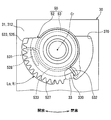
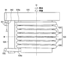
- FIG. 1 is a cross-sectional view showing a throttle valve device according to a first embodiment.
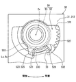
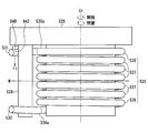
- FIG. 2 is a view showing an operating state of the throttle valve device according to the first embodiment, and is a cross-sectional view taken along the line II-II of FIG. 1;
- FIG. 3 is a view showing an operating state different from FIG. 2 and a cross-sectional view corresponding to FIG. 2.
- FIG. 5 is a view showing an operating state different from FIGS. 2 and 3 and a cross-sectional view corresponding to FIG. 2. It is a front view which shows typically the drive unit by 1st Embodiment.
- FIG. 2 is a view showing an operating state of the throttle valve device according to the first embodiment, and is a cross-sectional view taken along the line II-II of FIG. 1
- FIG. 3 is a view showing an operating state different from FIG. 2 and a cross-sectional view corresponding to FIG. 2.
- FIG. 5 is a view showing an operating state different from FIGS. 2
- FIG. 6 is a view on arrow VI of FIG. 5; It is a figure which shows the groove shape of a movable engagement part in VII arrow of FIG. It is a figure which shows the groove shape of a movable engagement part in VI arrow of FIG.
- FIG. 6 is a cross-sectional view taken along line IX-IX of FIG. 5;
- FIG. 6 is a cross-sectional view taken along the line XX in FIG. It is a perspective view of the torsion coil spring by 1st Embodiment, and a guide body. It is a figure which shows the groove shape of a movable engagement part by the 1st modification with respect to 1st Embodiment.
- FIG. 18 is a cross-sectional view taken along line XVIII-XVIII in FIG. It is a front view which shows the drive unit by 2nd Embodiment typically. It is XX arrow line view of FIG. It is a front view which shows typically a drive unit by the 1st modification with respect to 2nd Embodiment. It is a side view showing typically a drive unit by the 2nd modification to a 2nd embodiment.
- the throttle valve device 1 As shown in FIG. 1, the throttle valve device 1 according to the first embodiment is applied to an electric throttle device mounted on an internal combustion engine of a vehicle.
- the throttle valve device 1 opens and closes a fluid passage 2 which constitutes a part of an intake passage in an internal combustion engine.
- intake air which is drawn into the internal combustion engine as a fluid, flows.
- the throttle valve device 1 adjusts the flow rate of intake air flowing through the fluid passage 2.
- the throttle valve device 1 includes a throttle valve body 10, a valve shaft 20, a valve body 30, a drive unit 50, and a sensor unit 70.
- the throttle valve body 10 is a butterfly type rotary valve.
- the throttle valve body 10 is formed in a disk shape by metal.
- a rotation center line Cr is set substantially perpendicular to the passage axis Aa of the fluid passage 2.
- the throttle valve body 10 is accommodated in the fluid passage 2 so as to be rotatable on both sides around the rotation center line Cr.
- the throttle valve body 10 adjusts the flow rate of intake air in the fluid passage 2 by increasing or decreasing the degree of opening of the fluid passage 2 by rotation around the rotation center line Cr.
- the valve shaft 20 is a shaft for rotationally driving the throttle valve body 10.
- the valve stem 20 is formed of metal in an elongated round bar shape.
- the valve stem 20 crosses the fluid passage 2 by being disposed in a posture extending on the rotation center line Cr of the throttle valve body 10.
- the valve stem 20 is fastened to the throttle valve body 10 so as to be integrally rotatable.
- the valve body 30 is a fixed node fixed to an intake pipe forming an intake passage in an internal combustion engine.
- the valve body 30 is configured by combining a body 31, a body cover 32 and a body hook 33.
- the body main body 31 is formed in a block shape of metal.
- the body main body 31 has a bore portion 310 and housing portions 311 and 312.
- the fluid passage 2 penetrates through the bore portion 310 in a cylindrical hole shape that can be opened and closed by the disc-like throttle valve body 10.
- the housing portions 311 and 312 are respectively provided in a hollow shape on both sides of the bore portion 310 on the rotation center line Cr.
- the radial sliding bearing 34 is housed and fixed in the first housing portion 311.
- the radial sliding bearing 34 radially supports the outer peripheral surface of one end of the valve shaft 20.
- a radial rolling bearing 36 is housed and fixed.
- the radial rolling bearing 36 radially supports an outer peripheral surface of an intermediate portion between the end portions of the valve shaft 20.
- the body cover 32 is formed of resin in a flat plate shape.
- the body cover 32 covers the second accommodation portion 312 by being fastened to the body main body 31.
- the drive unit 50 and the sensor unit 70 are accommodated and disposed in the main accommodation space 37 in which the body cover 32 is formed jointly with the second accommodation portion 312.
- the body hook 33 is formed in a bent shape by metal.
- the body hook 33 is provided in the second housing portion 312 and thus protrudes into the main housing space 37.
- the body hook 33 has a fixed engagement portion 330 at a part where it enters into the main accommodation space 37.
- the fixed engagement portion 330 is formed in a substantially arcuate piece shape that extends in a part around the rotation center line Cr in the main housing space 37.
- the drive unit 50 is an electric actuator for rotationally driving the throttle valve body 10 via the valve shaft 20.
- the drive unit 50 is configured by combining a drive motor 51, a reduction mechanism 52, and a torsion coil spring 53.
- the drive motor 51 shown in FIG. 1 is an electric motor which rotates to both sides around the motor axis line Am by energization from an external control circuit.
- the drive motor 51 has a metal motor shaft 510 that generates a drive force by rotation.
- the reduction gear mechanism 52 shown in FIGS. 1 and 2 has a plurality of resin gears 520, 521, 522, and 523 connected in gear.
- the speed reduction mechanism 52 exhibits a rotational speed reduction function between the first gear 520 and the last gear 523.
- the first gear 520 is integrally rotatably mounted around the motor axis Am with respect to the coaxial motor shaft 510.
- the final-stage gear 523 is integrally fixed to the coaxial valve shaft 20 around the rotation center line Cr, and is thus integrally rotatable with the throttle valve body 10.
- the driving force hereinafter simply referred to as "driving force" input from the driving motor 51 to the first gear 520 is amplified by the rotational speed reduction function and transmitted from the last gear 523 to the valve shaft 20.
- driving force hereinafter simply referred to as "driving force”
- the throttle valve body 10 is rotated to a side corresponding to the drive force among both sides around the rotation center line Cr.
- the final stage gear 523 includes a rotating body 525 and a guide body 526.
- a meshing portion 527 and a movable engagement portion 528 are integrally provided in the generally cylindrical rotary body 525.
- the meshing portion 527 is formed in the shape of a partial spur gear that extends in a part around the rotation center line Cr in the main housing space 37.
- the meshing portion 527 meshes with the gear 522 on the front side of the final gear 523.
- the movable engagement portion 528 is formed in a substantially arc-like piece that extends in a part around the rotation center line Cr in the main housing space 37. In the present embodiment, the movable engagement portion 528 is disposed closer to the rotation center line Cr than the fixed engagement portion 330, that is, displaced radially inward of the fixed engagement portion 330.
- the rotational position of the rotating body 525 shown in FIGS. 1 and 2 is preset to a default position Ld in which the fluid passage 2 is slightly opened from the fully closed state by the throttle valve body 10. At this default position Ld, the rotor 525 is localized due to the loss of the driving force.
- the rotational position of the rotating body 525 shown in FIG. 3 is previously set to the fully open position Lo where the fluid passage 2 is fully opened by the throttle valve 10, ie, the maximum opening degree on product specifications.
- the meshing portion 527 is locked by the second accommodation portion 312 from the opposite side to the default position Ld, whereby the fluid passage 2 is opened in the rotational direction (hereinafter simply referred to as “open side” Rotation is restricted with respect to the rotating body 525. Therefore, on the open side of the default position Ld, a rotation area in which the rotary body 525 is rotationally driven by the generation of the driving force up to the fully open position Lo is defined as a large rotation area Rl.
- the rotational position of the rotating body 525 shown in FIG. 4 is preset to the fully closed position Lc where the fluid passage 2 is fully closed by the throttle valve body 10.
- the second accommodation portion 312 locks the meshing portion 527 from the opposite side to both the fully open position Lo and the default position Ld, thereby closing the fluid passage 2 in the rotational direction.
- the rotation to the side of the rotating body 525 (hereinafter referred to simply as the “closed side”) is restricted.
- the rotation area in which the rotary body 525 is rotationally driven by the generation of the driving force up to the fully closed position Lc is permitted as the small rotation area Rs than the large rotation area Rl It is defined in a small area of the rotation angle.
- the guide body 526 is formed in a cylindrical shape having an outer peripheral surface continuous around the rotation center line Cr in the main housing space 37.
- the guide body 526 is integrally formed coaxially with the meshing portion 527 of the rotating body 525.
- the guide body 526 is coaxially mounted on the valve stem 20 and can be integrated.
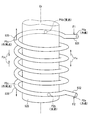
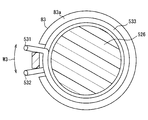
- the torsion coil spring 53 shown in FIGS. 1 and 2 is a torsion spring that is elastically deformed by torsion to generate a restoring force (hereinafter referred to as “torsion elastic force”).
- the torsion coil spring 53 is formed by winding a metal wire.
- the torsion coil spring 53 is disposed around the guide body 526.
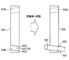
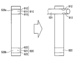
- the torsion coil spring 53 has a coil portion 533 between the hook portions 531 and 532 at both ends.
- the hook portions 531 and 532 are formed in a hook shape (i.e., a hook shape) bent or curved radially outward from the coil portion 533, respectively.
- the hook portions 531 and 532 both extend to the outer side in the radial direction than the movable engagement portion 528 and the fixed engagement portion 330.
- the first hook portion 531 is disposed closer to the meshing portion 527 than the second hook portion 532 in the axial direction along the rotation center line Cr.
- the first hook portion 531 engages with the movable engagement portion 528 that is at least one of the engagement portions 330 and 528 from the open side.
- the second hook portion 532 engages with the movable engagement portion 528 which is at least one of the engagement portions 330 and 528 from the closing side.
- the hooks 531 and 532 apply torsional elastic force to the opposite side with respect to the same engagement target, so that the rotating body 525 whose driving force disappears at the default position Ld is Maintain orientation.
- the torsion coil spring 53 is elastically deformed due to the torsion, and the hook portions 531 and 532 receive the reaction force from the engaging portions 330 and 528.
- the first hook portion 531 becomes the movable engagement portion 528 that becomes one of the engagement portions 330 and 528. , From the open side.
- the second hook portion 532 engages with the fixed engagement portion 330, which is the other of the engagement portions 330 and 528, from the closing side.
- the first hook portion 531 applies a torsional elastic force toward the closing side to the movable engaging portion 528 to be engaged, whereby the torsional elastic force and the drive in the large rotation area Rl are driven.
- the rotating body 525 rotates to a position where the force balances.
- the first hook portion 531 is one of the fixing portions 330 and 528.
- the engagement portion 330 is engaged from the open side.
- the second hook portion 532 engages with the movable engagement portion 528 which is the other of the engagement portions 330 and 528 from the closing side.
- the second hook portion 532 gives the movable engaging portion 528 to be engaged a torsional elastic force toward the release side, thereby causing the torsional elastic force in the small rotation region Rs
- the rotating body 525 rotates to a position where the driving force is balanced.
- the coil portion 533 is formed in a coil shape (i.e., a spiral shape) that leaves a gap between metal wires.
- the coil portion 533 is guided by the guide body 526 from the inside in the radial direction.
- the coil diameter from the coil center line Cc in the coil portion 533 is substantially constant between both ends.
- the sensor unit 70 is configured by combining a rotor magnet 71 and a sensor element 72.
- the rotor magnet 71 is a permanent magnet that constantly forms a magnetic field.
- the rotor magnet 71 is embedded in the rotating body 525 so as to be integrally rotatable.
- the sensor element 72 is a magnetoelectric conversion element that detects a magnetic field and outputs a detection signal, such as a Hall element.
- the sensor element 72 is embedded in the body cover 32.
- the sensor element 72 is disposed inward of the main housing space 37 in the radial direction of the rotating body 525 and the guide body 526.
- the detection signal output from the sensor element 72 represents the rotational position of the rotating body 525 according to the opening degree of the fluid passage 2 opened and closed by the throttle valve body 10. Therefore, the external control circuit can obtain the opening degree of the fluid passage 2 according to the rotational position of the rotating body 525 based on the detection signal output from the sensor element 72.
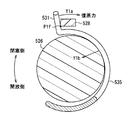
- the posture correction structure is described.
- the posture of the coil portion 533 tends to collapse due to the reaction force applied to the first hook portion 531 and the second hook portion 532 from the engaging portions 330 and 528.
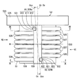
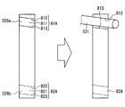
- the movable engagement portion 528 is engaged with the first groove 528a in which the first hook portion 531 is engaged and engaged and the second hook portion 532 And a second groove 528b to be engaged.
- the first groove 528a has a shape opening on the side of the first hook portion 531 (see FIG. 5) and a shape extending in the direction in which the wire of the first hook portion 531 extends, that is, the circumferential direction of the coil portion 533 (FIG. 6) See).
- a portion of the movable engagement portion 528 forming the first groove 528 a corresponds to the first pressing portion 81.
- the first pressing portion 81 has an engagement surface 811, a pressing surface 812 and an opposing surface 813.
- the engagement surface 811 is a flat surface extending perpendicularly to the tangent of the outer periphery of the coil portion 533.
- the pressing surface 812 and the opposing surface 813 are flat surfaces extending perpendicularly to the engagement surface 811.
- the pressing surface 812 is located on the side of the final stage gear 523 in the direction of the coil center line Cc, and the opposing surface 813 is located on the side of the center M (see FIGS. 5 and 6) of the coil center line Cc direction.
- the pressing face 812 of the first hook portion 531 has a tapered shape which is inclined in a direction approaching the center M as it is separated from the radial center of the coil portion 533 (see FIGS. 7 and 8).
- the end face on the meshing portion 527 side of the coil portion 533 in the direction of the coil center line Cc is referred to as a first end face 535a (see FIG. 6), and the end face on the throttle valve body 10 side is referred to as a second end face 536a.
- the distance from the first end surface 535a to the center M in the coil center line Cc direction is equal to the distance from the second end surface 536a to the center M.
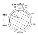
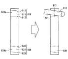
- the second groove 528 b has the same shape as the first groove 528 a, and the portion of the movable engagement portion 528 forming the second groove 528 b corresponds to the second pressing portion 82.
- the second pressing portion 82 has an engagement surface 821, a pressing surface 822 and an opposing surface 823.
- the pressing surface 822 is located on the side of the center M in the direction of the coil center line Cc, and the opposing surface 823 is located on the throttle valve body 10 side in the direction of the coil center line Cc.
- the pressing surface 822 of the second hook portion 532 has a tapered shape which is inclined in a direction approaching the center M as it is separated from the radial direction center of the coil portion 533.
- the pressing surface 812 of the first hook portion 531 is located closer to the center M than the first end surface 535 a in the coil center line Cc direction, and the pressing surface 822 of the second hook portion 532 is a coil It is located closer to the center M than the second end surface 536a in the direction of the center line Cc.
- a region where the first turn portion 535 on the meshing portion 527 side is located is referred to as a first region W1
- a region where the first turn portion 536 on the throttle valve body 10 side is located is the second region. It is called area W2.
- the entire first pressing portion 81 in the direction of the coil center line Cc is disposed in the first region W1
- the entire second pressing portion 82 in the direction of the coil center line Cc is disposed in the second region W2.
- the side surface of the first hook portion 531 fits into the first groove 528 a, and the engaging surface 811 is the first hook portion 531. It receives torsional elastic force from it. In other words, the first hook portion 531 receives a reaction force against the torsional elastic force from the engagement surface 811.
- the first hook portion 531 is disengaged from the first groove 528 a.
- the rotating body 525 rotates to the closing side from the default position or the default position
- the side surface of the second hook portion 532 fits into the second groove 528 b
- the engaging surface 821 is the second hook portion 532 It receives torsional elastic force from it.
- the second hook portion 532 receives a reaction force against the torsional elastic force from the engagement surface 821.
- the first pressing portion 81 presses against the first hook portion 531 and the second hook portion 532 separates from the second pressing portion 82.
- the second pressing portion 82 presses against the second hook portion 532 and the first hook portion 531 separates from the first pressing portion 81.
- FIGS. 9 and 10 show the state of a comparative example in which the grooves 528a and 528b are not formed contrary to the present embodiment.
- the engagement point P1f with the movable engagement portion 528 is engaged when the rotating body 525 stands still at the default position or rotates to the open side. Occurs around the fulcrum. Then, when the rotating body 525 rotates to the closing side, an engagement point with the fixed engaging portion 330 is generated as a fulcrum.
- the position of the coil center line Cc in the portion on the meshing portion 527 side of the coil portion 533 is the rotation center line Cr. With respect to the position, the first hook portion 531 is more eccentric than the target engaging portion.
- the engagement point P2 f with the movable engagement portion 528 is engaged when the rotating body 525 is stopped at the default position or rotated to the closing side. Occurs around the fulcrum.
- an engagement point with the fixed engaging portion 330 is generated as a fulcrum.
- the position of the coil center line Cc is the rotation center line Cr in the portion of the coil portion 533 on the throttle valve body 10 side due to the second hook portion 532 receiving a reaction force from the target engaging portion.
- the second hook portion 532 is more eccentric than the target engaging portion.
- the posture of the coil portion 533 is broken.
- the coil center line Cc does not become straight, if the collapse of the posture is described in detail below.
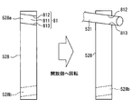
- the coil center line Ccx in the above-described modification looks straight when viewed from the extending direction of the first hook portion 531 and the second hook portion 532 as shown in FIG. 5, the coil center line Ccx in FIG. Tilts with respect to the rotation center line Cr. Further, the coil portion 533 in the above modification is deformed as follows.
- the portions on the side of the hook portions 531 and 532 in the circumferential direction of the coil portion 533 are deformed so as to be stretched in the direction of the coil center line Cc as shown by the arrow Fx in FIG.
- the portion on the non-hook portion side in the circumferential direction of the coil portion 533 is deformed so as to be compressed in the direction of the coil center line Cc as shown by the arrow Fy in FIG.
- the correction of the posture referred to here is correction in which the coil center line Cc is made close to a straight line and correction in which the inclination of the coil center line Cc with respect to the rotation center line Cr is suppressed.
- the pressing surfaces 812 and 822 hit the hook portions 531 and 532 and the pressing force is directed to the center M of the coil center line Cc. It is formed in the structure given to. Therefore, deformation in the compression direction of the non-hook portion side portion of the coil portion 533 caused by the hook portions 531 and 532 receiving a reaction force from the engagement surfaces 811 and 821 acts on the action points P1 c, It is relieved by pressing forces F1 and F2 acting on P2c. Thus, the posture of the coil portion 533 can be corrected.
- the pressing forces F1 and F2 applied to the hook portions 531 and 532 by the pressing faces 812 and 822 are inclined with respect to the rotation center line Cr and the coil center line Cc. It is also good. Even if the pressing direction is inclined, the component of the force in the direction of the coil center line Cc acts as the pressing forces F1 and F2, and the effect of posture correction is exhibited.
- the required accuracy in the pressing direction is lower than in the conventional structure pressing from the outer peripheral side. As a result, posture correction can be easily realized.
- the default position Ld is the fully closed position Lc or the default position Ld.
- the torque required for the rotation of the rotating body 525 has a hysteresis in the range from the point L.sub. And there is a concern that the hysteresis is increased as the wear is larger. Therefore, when the posture of the coil portion 533 is corrected by the present embodiment, an effect of reducing these concerns is exhibited.
- the pressing portions 81 and 82 apply the pressing force F2 to the first hook portion 531 and the second pressing portion 81 to apply the pressing force F1 to the first hook portion 531. And a pressing portion 82. Therefore, since the pressing forces F1 and F2 contributing to the posture correction are applied from both hook portions 531 and 532, the certainty of the posture correction can be improved as compared with the case of applying from either one.
- the first pressing portion 81 and the second pressing portion 82 are provided in the movable engagement portion 528. Then, when the rotating body 525 is rotating from the default position to one side, the first pressing portion 81 presses against the first hook portion 531 and the second hook portion 532 separates from the second pressing portion 82. Conversely, when the rotating body 525 is rotating from the default position to the other side, the second pressing portion 82 presses against the second hook portion 532 and the first hook portion 531 separates from the first pressing portion 81 .
- two of the first pressing portion 81 and the second pressing portion 82 are provided. Therefore, at least one of the two pressing portions 81 and 82 applies a pressing force. Thus, the pressing force can be always applied.
- the movable engagement portion 528 includes a first groove 528a in which the first hook portion 531 is fitted and engaged, and a second groove 528b in which the second hook portion 532 is engaged and engaged. It is formed. Further, pressing faces 812 and 822 which press against the hook portions 531 and 532 of the pressing portions 81 and 82 are formed on the inner wall surfaces of the grooves 528 a and 528 b. Therefore, since the hook portions 531 and 532 are engaged with the grooves 528a and 528b, the engagement and the application of the pressing force are performed, so that a part of the movable engaging portion 528 can be used as the pressing portions 81 and 82.
- the valve device 1 can be miniaturized.
- the pressing face 812 pressing against the first hook portion 531 in the first pressing portion 81 is closer to the center M than the end face 535a on the meshing portion 527 side of the coil portion 533 in the coil centerline Cc direction.
- the pressing surface 822 pressed against the second hook portion 532 is located closer to the center M than the end face 535b on the throttle valve body 10 side of the coil portion 533 in the direction of the coil center line Cc.
- the first pressing portion 81 is disposed in the first region W1 in which the first turn portion 535 is located in the direction of the coil center line Cc.
- at least a portion of the second pressing portion 82 is disposed in the second region W2 in which the first turn portion 536 is located in the direction of the coil center line Cc. Therefore, it can be precisely realized that the direction in which the pressing portions 81, 82 press against the hook portions 531, 532 is the center M side, and the pressing forces F1, F2 can be easily obtained.
- the pressing surfaces 812 and 822 formed in the pressing portions 81 and 82 have a tapered shape that is inclined in a direction approaching the center M as the distance from the radial center of the coil portion 533 increases. Therefore, as shown in FIG. 11, when rotating the first turn portions 535 and 536 in the direction opposite to the arrow Fy with the contact portions P1b and P2b of the coil portion 533 and the guide body 526 as a fulcrum, The corresponding parts 81 and 82 will be pushed. Therefore, it is possible to improve the certainty of alleviating the deformation in the compression direction of the non-hook portion side of the coil portion 533.
- the pressing surfaces 812 and 822 and the opposite surfaces 813 and 823 both hook portions 531 and 532 in the state in which the hook portions 531 and 532 are fitted in the grooves 528 a and 528 b.
- the widths of the grooves 528a and 528b are the same as the diameter of the metal wire.
- the widths of the grooves 528a and 528b may be set to be larger than the diameter of the metal wire as in the pressing portions 81A and 82A shown in FIG. In this case, pressing forces F1 and F2 are applied to the hook portions 531 and 532 by the pressing surfaces 812 and 822 coming into contact with the hook portions 531 and 532, respectively.
- the pressing surfaces 812 and 822 and the opposing surfaces 813 and 823 are both formed in a tapered shape.
- the opposing surfaces 813 and 823 extend perpendicularly to the coil center line Cc. It may be non-tapered.
- both the pressing surfaces 812 and 822 and the opposing surfaces 813 and 823 are both formed in a tapered shape.
- both the pressing surfaces 812 and 822 and the opposing surfaces 813 and 823 have a non-tapered shape extending perpendicularly to the coil center line Cc. It is also good.
- a fourth modification to the first embodiment will be described.
- the pressing surfaces 812 and 822 and the opposing surfaces 813 and 823 both contact the outer peripheral surfaces of the hook portions 531 and 532 doing. That is, the widths of the grooves 528a and 528b are the same as the diameter of the metal wire.
- the width of the grooves 528a and 528b is a metal wire It may be set larger than the diameter of.
- the pressing surfaces 812 and 822 and the opposing surfaces 813 and 823 are disposed at right angles to each other, and the grooves 528 a and 528 b are square in cross section.
- the grooves 528a and 528b may have a circular arc shape in cross section as in the pressing portions 81E and 82E shown in FIG.
- the grooves 528a and 528b have a cross-sectional shape in which the opening area gradually increases as the hook portions 531 and 532 move away from the grooves 528a and 528b as the rotating body 525 rotates.
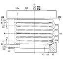
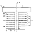
- a push-up portion 83 which pushes a part of the coil portion 533 toward the center M in the direction of the coil center line Cc.
- the pushing portion 83 is disposed in the rotation area of the hook portions 531 and 532.
- the reference symbol W3 in the drawing indicates a region other than the rotation region of the hook portions 531 and 532.
- the push-up portion 83 is provided over the entire rotation area.
- the pushing force F3 is applied to the first-roll portion 536 on the throttle valve body 10 side in a region out of the rotation region where the pushing force 822 applies the pushing force F2.
- the pushing force F3 is applied toward the center M in the direction of the coil center line Cc.
- the push-up portion 83 is attached to and supported by the body main body 31 shown in FIG.
- the push-up portion 83 has a tapered surface 83 a in contact with the first turn portion 536 on the throttle valve body 10 side.
- the tapered surface 83 a is shaped so as to be inclined toward the throttle valve body 10 in the direction of the coil center line Cc as it approaches the coil center line Cc in the radial direction.
- the lifting force F3 is also applied to the coil portion 533, so that the posture correction of the coil portion 533 can be promoted.
- the movable engaging portion 528 is made to function as the pressing portions 81 and 82 by forming the grooves 528 a and 528 b having the pressing surfaces 812 and 822 in the movable engaging portion 528.
- the grooves 528a and 528b are eliminated, and a protruding pressing portion 84 is provided on the rotating body 525.
- the resin rotating body 525 and the pressing portion 84 are integrally molded.
- the pressing portion 84 has a pressing surface 842 pressing against the first hook portion 531.
- the pressing surface 842 applies the pressing force F1 to the first hook portion 531 in the same manner as the pressing surface 812 of the first pressing portion 81.
- the posture of the coil portion 533 can be corrected also in the present embodiment in which the groove 528 a is replaced with the pressing portion 84.
- the pressing surface 842 pressing against the first hook portion 531 in the pressing portion 84 is positioned closer to the center M than the end surface 535a on the meshing portion 527 side of the coil portion 533 in the coil centerline Cc direction.
- the direction in which the pressing portion 84 presses against the first hook portion 531 is the center M side, and the pressing force F1 can be easily obtained. Furthermore, in the present embodiment, at least a portion of the pressing portion 84 is disposed in the first region W1 in which the first turn portion 535 is located in the direction of the coil center line Cc. Therefore, it can be precisely realized that the direction in which the pressing portion 84 presses against the first hook portion 531 is the center M side, and the pressing force F1 can be easily obtained.
- a first modification to the second embodiment will be described.
- the pressing portion 84 is pressed against the first hook portion 531 and pressed. Force F1 is applied.
- the pressing portion 84 is separated from the first hook portion 531 and does not apply the pressing force F1. That is, the pressing portion 84 is not disposed in the entire rotation area of the first hook portion 531.
- the pressing portion 84 ⁇ / b> A may be disposed in the entire rotation area of the first hook portion 531. According to this, even when the first hook portion 531 is engaged with the fixed engagement portion 330, the pressing portion 84 can contact the first hook portion 531 and can apply the pressing force F1. Therefore, the effect of posture correction of the coil portion 533 can be improved.
- the pressing portion 84 is provided on the rotating body 525, and the pressing portion 84 has a shape projecting in the direction of the coil center line Cc.
- the movable engaging portion 528 may be provided with a pressing portion 84B.
- the pressing portion 84B in this case has a shape protruding in the radial direction of the coil portion 533.
- the movable engagement portion 528 is made to function as the pressing portions 81 and 82 by forming the grooves 528 a and 528 b in the movable engagement portion 528.
- a part of the fixed engagement portion 330 may be functioned as a pressing portion by forming a groove in the fixed engagement portion 330.
- grooves may be formed in both the movable engagement portion 528 and the fixed engagement portion 330, and both the movable engagement portion 528 and the fixed engagement portion 330 may function as a pressing portion.
- first hook portion 531 and the second hook portion 532 are engaged with one movable engaging portion 528, the first hook portion 531 and the second hook portion 532 are separately operated in different movable engaging portions. Each hook 532 may be engaged.
- the entire pressing portions 81 and 82 are disposed in the first area W1 and the second area W2.
- at least a part of the pressing parts 81 and 82 is disposed in the first area W1 and the second area W2, that is, a part of the pressing parts 81 and 82 is out of these areas W1 and W2 It may be arranged.
- the pressing portion 84 shown in FIGS. 19 and 20 is disposed at a position away from the movable engaging portion 528, and is disposed so as to press against the tip of the first hook portion 531.
- the pressing portion 84 may be disposed so as to be adjacent to the movable engagement portion 528 and to press against a position away from the tip of the first hook portion 531.
- the guide body 526 is integrally molded with the rotary body 525 so that the guide body 526 rotates integrally with the rotary body 525.
- the guide body 526 is separate from the rotary body 525 It may be formed in
- the fixed engagement portion 330 may be disposed radially inward of the movable engagement portion 528.
- a fixed engagement The portion 330 may be engaged in the default position Ld, in addition to or instead of engaging at least one of the first turn portions 535 and 536 in the coil portion 533 with the movable engagement portion 528.
- one of the rotation areas Rl and Rs may not be set.
- the first hook portion 531 at the default position Ld when the small rotation area Rs is not set, the first hook portion 531 further engages with the movable engagement portion 528 and the second hook portion 532 engages with the fixed engagement portion 330. It is also good. Further, at the default position Ld when the large rotation area Rl is not set, the first hook portion 531 may be engaged with the fixed engagement portion 330 and the second hook portion 532 may be engaged with the movable engagement portion 528. .
- the present disclosure may be applied to, for example, a throttle valve device or the like having a fluid passage 2 through which exhaust gas of an internal combustion engine flows, as a modification of each of the above embodiments.
- the exhaust gas recirculation (EGR (Exhaust Gas Recirculation) device is a throttle valve device having a fluid passage 2 through which exhaust gas flows, or a throttle valve having a fluid passage 2 through which exhaust gas flows and also intake air flows. It is an example of an apparatus.
Landscapes
- Engineering & Computer Science (AREA)
- General Engineering & Computer Science (AREA)
- Mechanical Engineering (AREA)
- Chemical & Material Sciences (AREA)
- Combustion & Propulsion (AREA)
- Control Of Throttle Valves Provided In The Intake System Or In The Exhaust System (AREA)
Priority Applications (3)
| Application Number | Priority Date | Filing Date | Title |
|---|---|---|---|
| CN201880044777.4A CN110869594B (zh) | 2017-07-07 | 2018-06-26 | 节流阀装置 |
| DE112018003440.2T DE112018003440B4 (de) | 2017-07-07 | 2018-06-26 | Drosselventilvorrichtung |
| US16/733,402 US11248714B2 (en) | 2017-07-07 | 2020-01-03 | Throttle valve device |
Applications Claiming Priority (2)
| Application Number | Priority Date | Filing Date | Title |
|---|---|---|---|
| JP2017-133974 | 2017-07-07 | ||
| JP2017133974A JP6720930B2 (ja) | 2017-07-07 | 2017-07-07 | 絞り弁装置 |
Related Child Applications (1)
| Application Number | Title | Priority Date | Filing Date |
|---|---|---|---|
| US16/733,402 Continuation US11248714B2 (en) | 2017-07-07 | 2020-01-03 | Throttle valve device |
Publications (1)
| Publication Number | Publication Date |
|---|---|
| WO2019009133A1 true WO2019009133A1 (ja) | 2019-01-10 |
Family
ID=64950040
Family Applications (1)
| Application Number | Title | Priority Date | Filing Date |
|---|---|---|---|
| PCT/JP2018/024094 Ceased WO2019009133A1 (ja) | 2017-07-07 | 2018-06-26 | 絞り弁装置 |
Country Status (5)
| Country | Link |
|---|---|
| US (1) | US11248714B2 (enExample) |
| JP (1) | JP6720930B2 (enExample) |
| CN (1) | CN110869594B (enExample) |
| DE (1) | DE112018003440B4 (enExample) |
| WO (1) | WO2019009133A1 (enExample) |
Cited By (2)
| Publication number | Priority date | Publication date | Assignee | Title |
|---|---|---|---|---|
| CN112594469A (zh) * | 2020-11-24 | 2021-04-02 | 中国人民解放军96901部队24分队 | 一种基于液压缸销轴的可变节流旋转接头 |
| EP3913202A4 (en) * | 2019-01-15 | 2022-03-16 | Shanghai Auzone Auto Parts Manufacturing Co., Ltd | RETURN MECHANISM FOR ELECTRONIC THROTTLE VALVE |
Families Citing this family (5)
| Publication number | Priority date | Publication date | Assignee | Title |
|---|---|---|---|---|
| JP7004638B2 (ja) * | 2018-12-18 | 2022-01-21 | 株式会社デンソー | スロットル装置、及び、スロットル装置の製造方法 |
| WO2021176489A1 (ja) * | 2020-03-02 | 2021-09-10 | 愛三工業株式会社 | スロットル装置 |
| JP7392619B2 (ja) * | 2020-09-29 | 2023-12-06 | 株式会社デンソー | バルブ装置 |
| JP7428925B2 (ja) * | 2022-06-10 | 2024-02-07 | 株式会社デンソーダイシン | 絞り弁装置及び絞り弁装置の製造方法 |
| JP2024022108A (ja) * | 2022-08-05 | 2024-02-16 | 愛三工業株式会社 | スロットル装置 |
Citations (4)
| Publication number | Priority date | Publication date | Assignee | Title |
|---|---|---|---|---|
| WO2000068555A1 (en) * | 1999-05-10 | 2000-11-16 | Hitachi, Ltd. | Throttle device of internal combustion engine |
| JP2012041887A (ja) * | 2010-08-20 | 2012-03-01 | Denso Corp | 電子スロットル |
| JP2015124646A (ja) * | 2013-12-26 | 2015-07-06 | 株式会社マーレ フィルターシステムズ | 吸気制御弁の組付構造及び組付方法 |
| JP2016020653A (ja) * | 2014-07-14 | 2016-02-04 | 愛三工業株式会社 | 絞り弁制御装置 |
Family Cites Families (13)
| Publication number | Priority date | Publication date | Assignee | Title |
|---|---|---|---|---|
| DE3890168C2 (de) * | 1987-03-02 | 1996-10-02 | Mitsubishi Electric Corp | Rückstelleinrichtung für eine Drosselklappe eines Verbrennungsmotors |
| JP3038282B2 (ja) * | 1993-04-12 | 2000-05-08 | 株式会社日立製作所 | スロットル弁開閉装置 |
| WO2000068556A1 (en) * | 1999-05-10 | 2000-11-16 | Hitachi, Ltd. | Throttle device of internal combustion engine |
| DE10043001A1 (de) | 2000-09-01 | 2002-03-14 | Pierburg Ag | Klammerfederanordnung bei einem Drosselklappenstutzen einer Brennkraftmaschine |
| JP2004150324A (ja) * | 2002-10-30 | 2004-05-27 | Denso Corp | 電子制御式スロットル制御装置 |
| DE602004015940D1 (de) * | 2003-03-07 | 2008-10-02 | Denso Corp | Elektronische Drosselklappensteuereinrichtung |
| JP2005030296A (ja) * | 2003-07-11 | 2005-02-03 | Aisan Ind Co Ltd | スロットル制御装置 |
| JP4457038B2 (ja) * | 2005-04-14 | 2010-04-28 | 日立オートモティブシステムズ株式会社 | 内燃機関のモータ駆動式絞り弁制御装置 |
| JP4651588B2 (ja) * | 2006-07-14 | 2011-03-16 | 株式会社デンソー | バルブ開閉制御装置 |
| JP5971276B2 (ja) | 2014-04-25 | 2016-08-17 | 株式会社デンソー | アクチュエータおよびその組付方法 |
| JP6392146B2 (ja) | 2015-03-10 | 2018-09-19 | 愛三工業株式会社 | スロットル装置 |
| JP2017067067A (ja) * | 2015-09-30 | 2017-04-06 | 株式会社デンソー | 捩りばね |
| JP2019015249A (ja) | 2017-07-07 | 2019-01-31 | 株式会社デンソー | 絞り弁装置 |
-
2017
- 2017-07-07 JP JP2017133974A patent/JP6720930B2/ja not_active Expired - Fee Related
-
2018
- 2018-06-26 CN CN201880044777.4A patent/CN110869594B/zh not_active Expired - Fee Related
- 2018-06-26 DE DE112018003440.2T patent/DE112018003440B4/de active Active
- 2018-06-26 WO PCT/JP2018/024094 patent/WO2019009133A1/ja not_active Ceased
-
2020
- 2020-01-03 US US16/733,402 patent/US11248714B2/en active Active
Patent Citations (4)
| Publication number | Priority date | Publication date | Assignee | Title |
|---|---|---|---|---|
| WO2000068555A1 (en) * | 1999-05-10 | 2000-11-16 | Hitachi, Ltd. | Throttle device of internal combustion engine |
| JP2012041887A (ja) * | 2010-08-20 | 2012-03-01 | Denso Corp | 電子スロットル |
| JP2015124646A (ja) * | 2013-12-26 | 2015-07-06 | 株式会社マーレ フィルターシステムズ | 吸気制御弁の組付構造及び組付方法 |
| JP2016020653A (ja) * | 2014-07-14 | 2016-02-04 | 愛三工業株式会社 | 絞り弁制御装置 |
Cited By (3)
| Publication number | Priority date | Publication date | Assignee | Title |
|---|---|---|---|---|
| EP3913202A4 (en) * | 2019-01-15 | 2022-03-16 | Shanghai Auzone Auto Parts Manufacturing Co., Ltd | RETURN MECHANISM FOR ELECTRONIC THROTTLE VALVE |
| CN112594469A (zh) * | 2020-11-24 | 2021-04-02 | 中国人民解放军96901部队24分队 | 一种基于液压缸销轴的可变节流旋转接头 |
| CN112594469B (zh) * | 2020-11-24 | 2022-06-28 | 中国人民解放军96901部队24分队 | 一种基于液压缸销轴的可变节流旋转接头 |
Also Published As
| Publication number | Publication date |
|---|---|
| JP6720930B2 (ja) | 2020-07-08 |
| DE112018003440T5 (de) | 2020-04-09 |
| DE112018003440B4 (de) | 2024-07-11 |
| CN110869594A (zh) | 2020-03-06 |
| JP2019015248A (ja) | 2019-01-31 |
| US11248714B2 (en) | 2022-02-15 |
| CN110869594B (zh) | 2022-06-17 |
| US20200141511A1 (en) | 2020-05-07 |
Similar Documents
| Publication | Publication Date | Title |
|---|---|---|
| WO2019009133A1 (ja) | 絞り弁装置 | |
| JP6332463B2 (ja) | 電動式パワーステアリング装置 | |
| CN109563910B (zh) | 蜗轮减速器 | |
| JP4518147B2 (ja) | バルブタイミング調整装置 | |
| WO2014077310A1 (ja) | 遠心圧縮機 | |
| KR20040037143A (ko) | 액추에이터 | |
| JP2011252482A (ja) | スロットル装置 | |
| JP2015052387A (ja) | ボールねじ装置 | |
| JP7320367B2 (ja) | 開閉部材駆動装置 | |
| US11105272B2 (en) | Throttle device | |
| JP2019019975A (ja) | 二重偏心弁 | |
| US9441548B2 (en) | Acceleration device | |
| JP7522603B2 (ja) | 電動式ガス流量調節弁 | |
| CN113195880B (zh) | 节流阀装置及节流阀装置的制造方法 | |
| WO2019009134A1 (ja) | 絞り弁装置 | |
| WO2019012850A1 (ja) | 二重偏心弁 | |
| JP2005299413A (ja) | スロットル制御装置 | |
| US20110025314A1 (en) | Angle detector | |
| JP4918942B2 (ja) | ボールねじ | |
| JP7194607B2 (ja) | 回転駆動機構 | |
| CN112127733B (zh) | 用于门或窗的翼扇的驱动装置 | |
| JP4798421B2 (ja) | 電磁クラッチ | |
| JP6443310B2 (ja) | 弁装置 | |
| JP4535276B2 (ja) | 操舵比変更アクチュエータ | |
| JP2023022882A (ja) | 逆入力遮断クラッチ |
Legal Events
| Date | Code | Title | Description |
|---|---|---|---|
| 121 | Ep: the epo has been informed by wipo that ep was designated in this application |
Ref document number: 18828038 Country of ref document: EP Kind code of ref document: A1 |
|
| 122 | Ep: pct application non-entry in european phase |
Ref document number: 18828038 Country of ref document: EP Kind code of ref document: A1 |