JP7004638B2 - スロットル装置、及び、スロットル装置の製造方法 - Google Patents
スロットル装置、及び、スロットル装置の製造方法 Download PDFInfo
- Publication number
- JP7004638B2 JP7004638B2 JP2018236469A JP2018236469A JP7004638B2 JP 7004638 B2 JP7004638 B2 JP 7004638B2 JP 2018236469 A JP2018236469 A JP 2018236469A JP 2018236469 A JP2018236469 A JP 2018236469A JP 7004638 B2 JP7004638 B2 JP 7004638B2
- Authority
- JP
- Japan
- Prior art keywords
- gear
- spring
- valve
- guide
- valve gear
- Prior art date
- Legal status (The legal status is an assumption and is not a legal conclusion. Google has not performed a legal analysis and makes no representation as to the accuracy of the status listed.)
- Active
Links
Images


Classifications
-
- F—MECHANICAL ENGINEERING; LIGHTING; HEATING; WEAPONS; BLASTING
- F02—COMBUSTION ENGINES; HOT-GAS OR COMBUSTION-PRODUCT ENGINE PLANTS
- F02D—CONTROLLING COMBUSTION ENGINES
- F02D9/00—Controlling engines by throttling air or fuel-and-air induction conduits or exhaust conduits
- F02D9/08—Throttle valves specially adapted therefor; Arrangements of such valves in conduits
- F02D9/10—Throttle valves specially adapted therefor; Arrangements of such valves in conduits having pivotally-mounted flaps
- F02D9/1075—Materials, e.g. composites
- F02D9/108—Plastics
-
- F—MECHANICAL ENGINEERING; LIGHTING; HEATING; WEAPONS; BLASTING
- F02—COMBUSTION ENGINES; HOT-GAS OR COMBUSTION-PRODUCT ENGINE PLANTS
- F02D—CONTROLLING COMBUSTION ENGINES
- F02D9/00—Controlling engines by throttling air or fuel-and-air induction conduits or exhaust conduits
- F02D9/08—Throttle valves specially adapted therefor; Arrangements of such valves in conduits
- F02D9/10—Throttle valves specially adapted therefor; Arrangements of such valves in conduits having pivotally-mounted flaps
- F02D9/1065—Mechanical control linkage between an actuator and the flap, e.g. including levers, gears, springs, clutches, limit stops of the like
-
- F—MECHANICAL ENGINEERING; LIGHTING; HEATING; WEAPONS; BLASTING
- F02—COMBUSTION ENGINES; HOT-GAS OR COMBUSTION-PRODUCT ENGINE PLANTS
- F02D—CONTROLLING COMBUSTION ENGINES
- F02D11/00—Arrangements for, or adaptations to, non-automatic engine control initiation means, e.g. operator initiated
- F02D11/06—Arrangements for, or adaptations to, non-automatic engine control initiation means, e.g. operator initiated characterised by non-mechanical control linkages, e.g. fluid control linkages or by control linkages with power drive or assistance
- F02D11/10—Arrangements for, or adaptations to, non-automatic engine control initiation means, e.g. operator initiated characterised by non-mechanical control linkages, e.g. fluid control linkages or by control linkages with power drive or assistance of the electric type
-
- F—MECHANICAL ENGINEERING; LIGHTING; HEATING; WEAPONS; BLASTING
- F02—COMBUSTION ENGINES; HOT-GAS OR COMBUSTION-PRODUCT ENGINE PLANTS
- F02D—CONTROLLING COMBUSTION ENGINES
- F02D9/00—Controlling engines by throttling air or fuel-and-air induction conduits or exhaust conduits
- F02D9/08—Throttle valves specially adapted therefor; Arrangements of such valves in conduits
- F02D9/10—Throttle valves specially adapted therefor; Arrangements of such valves in conduits having pivotally-mounted flaps
- F02D9/1035—Details of the valve housing
- F02D9/104—Shaping of the flow path in the vicinity of the flap, e.g. having inserts in the housing
-
- F—MECHANICAL ENGINEERING; LIGHTING; HEATING; WEAPONS; BLASTING
- F02—COMBUSTION ENGINES; HOT-GAS OR COMBUSTION-PRODUCT ENGINE PLANTS
- F02D—CONTROLLING COMBUSTION ENGINES
- F02D9/00—Controlling engines by throttling air or fuel-and-air induction conduits or exhaust conduits
- F02D9/08—Throttle valves specially adapted therefor; Arrangements of such valves in conduits
- F02D9/10—Throttle valves specially adapted therefor; Arrangements of such valves in conduits having pivotally-mounted flaps
- F02D9/107—Manufacturing or mounting details
-
- F—MECHANICAL ENGINEERING; LIGHTING; HEATING; WEAPONS; BLASTING
- F02—COMBUSTION ENGINES; HOT-GAS OR COMBUSTION-PRODUCT ENGINE PLANTS
- F02D—CONTROLLING COMBUSTION ENGINES
- F02D11/00—Arrangements for, or adaptations to, non-automatic engine control initiation means, e.g. operator initiated
- F02D11/06—Arrangements for, or adaptations to, non-automatic engine control initiation means, e.g. operator initiated characterised by non-mechanical control linkages, e.g. fluid control linkages or by control linkages with power drive or assistance
- F02D11/10—Arrangements for, or adaptations to, non-automatic engine control initiation means, e.g. operator initiated characterised by non-mechanical control linkages, e.g. fluid control linkages or by control linkages with power drive or assistance of the electric type
- F02D2011/101—Arrangements for, or adaptations to, non-automatic engine control initiation means, e.g. operator initiated characterised by non-mechanical control linkages, e.g. fluid control linkages or by control linkages with power drive or assistance of the electric type characterised by the means for actuating the throttles
- F02D2011/102—Arrangements for, or adaptations to, non-automatic engine control initiation means, e.g. operator initiated characterised by non-mechanical control linkages, e.g. fluid control linkages or by control linkages with power drive or assistance of the electric type characterised by the means for actuating the throttles at least one throttle being moved only by an electric actuator
-
- F—MECHANICAL ENGINEERING; LIGHTING; HEATING; WEAPONS; BLASTING
- F02—COMBUSTION ENGINES; HOT-GAS OR COMBUSTION-PRODUCT ENGINE PLANTS
- F02D—CONTROLLING COMBUSTION ENGINES
- F02D9/00—Controlling engines by throttling air or fuel-and-air induction conduits or exhaust conduits
- F02D9/02—Controlling engines by throttling air or fuel-and-air induction conduits or exhaust conduits concerning induction conduits
Landscapes
- Engineering & Computer Science (AREA)
- Chemical & Material Sciences (AREA)
- Combustion & Propulsion (AREA)
- Mechanical Engineering (AREA)
- General Engineering & Computer Science (AREA)
- Manufacturing & Machinery (AREA)
- Control Of Throttle Valves Provided In The Intake System Or In The Exhaust System (AREA)
Description
そして、バルブギヤとスプリングとガイドとが組付けられて構成されたバルブギヤサブアセンブリ(701-704)がボデーのバルブギヤ収容室(13)に収容され、スプリングの第2フックがボデーに係止されている。また、シャフトがバルブギヤのボス部に固定されている。
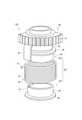
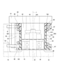
第1実施形態について、図1~図6を参照して説明する。最初に図1を参照し、スロットル装置100の全体構成を説明する。スロットル装置100は、吸気通路11が形成されたボデー10に、スロットルバルブ31、シャフト32、バルブギヤ40、スプリング50、アクチュエータ80、中間ギヤ82等の部品が組み付けられ、カバー20が被せられている。図中、吸気通路11の中心をx軸とし、x軸に直交する平面、すなわち図1の紙面において互いに直交する2軸をy軸及びz軸とする。
上記第1実施形態のスロットル装置100、及び、スロットル装置100の製造方法の効果は、以下の通りである。
次に、バルブギヤサブアセンブリにおけるガイドの構成を第1実施形態から一部変更した第2~第4実施形態について説明する。各実施形態のガイド及びバルブギヤサブアセンブリの符号は、それぞれ、「60」及び「70」に続く3桁目に実施形態の番号を付す。また、ガイドが二分割された第1ガイド及び第2ガイドの符号は、「61」及び「62」に続く3桁目に実施形態の番号を付す。
図8に示すように、第3実施形態のバルブギヤサブアセンブリ703において、ガイド603は、軸方向に二つに分割された第1ガイド613及び第2ガイド623からなる。第1ガイド613及び第2ガイド623は、ツバ部66及び側壁部67に加え、ガイド本体65の軸方向端部から周方向の一部において径外方向に突出し、第1フック51及び第2フック52を覆うフード部68を有する。これにより、第2フック52とボデー係止部16との当接箇所における接触面積が増加し、面圧が低下するため、ボデー10の摩耗量が低減する。また、初期回転位置における第2フック52とボデー係止部16との隙間が減り、ガタつきが抑制される。
図9に示すように、第4実施形態のバルブギヤサブアセンブリ704において、ガイド604は、軸方向に二つに分割された第1ガイド614及び第2ガイド624からなる。第1ガイド614及び第2ガイド624は、円筒状のガイド本体65のみで構成され、第1~第3実施形態のようなツバ部66、側壁部67、フード部68を有していない。この構成でもバルブギヤ40とスプリング50とが直接摺動しないため、バルブギヤ40を摺動性の良い材料で成形する必要がなく、材料コストを低減可能である。
(a)上記第1~第4実施形態は、いずれもガイド601-604を備えている。ただし、材料コスト低減の要求が低い場合や摺動性の良い材料を低コストで入手可能な場合等には、バルブギヤ40を摺動性の良い材料で成形することにより、ガイドを備えなくてもよい。
10・・・ボデー、 11・・・吸気通路、 13・・・バルブギヤ収容室、
31・・・スロットルバルブ、 32・・・シャフト、
40・・・バルブギヤ、 41・・・ギヤ部、 42・・・ボス部、
425・・・外壁、 45・・・延出部、
50・・・スプリング、 51・・・第1フック、 52・・・第2フック、
701-704・・・バルブギヤサブアセンブリ、
80・・・アクチュエータ。
Claims (7)
- 吸気通路(11)が形成されたボデー(10)と、
前記吸気通路に設けられ、開度が調整されるスロットルバルブ(31)と、
前記ボデーに回転自在に支持され、前記スロットルバルブが固定されたシャフト(32)と、
駆動トルクを出力するアクチュエータ(80)と、
前記アクチュエータから伝達される駆動トルクにより回動するギヤ部(41)、前記ギヤ部に設けられ、円筒状の外壁(425)を有するボス部(42)、及び、前記ボス部の径方向外側において前記ギヤ部から軸方向に延出する一つ以上の延出部(45)が一体に形成されたバルブギヤ(40)と、
前記バルブギヤの前記ボス部の外壁に外挿され、前記ギヤ部側の端部に設けられた第1フック(51)、及び、前記ギヤ部とは反対側の端部に設けられた第2フック(52)が前記延出部の周方向における互いに反対側にそれぞれ係止されたコイル状のスプリング(50)と、
前記ボス部の外壁と前記スプリングの内周との間に円筒状のガイド本体(65)を有し、少なくとも軸方向の前記ギヤ部側において、前記ギヤ部の回動に伴う前記ボス部と前記スプリングとの摺動を緩衝するガイド(601-604)と、
を備え、
前記バルブギヤと前記スプリングと前記ガイドとが組付けられて構成されたバルブギヤサブアセンブリ(701-704)が前記ボデーのバルブギヤ収容室(13)に収容され、前記スプリングの前記第2フックが前記ボデーに係止されており、
且つ、前記シャフトが前記バルブギヤの前記ボス部に固定されているスロットル装置。 - 前記ガイドは、軸方向に二つに分割されている請求項1に記載のスロットル装置。
- 少なくとも一つの前記ガイド(601-603)は、前記ガイド本体の軸方向端部から径外方向に突出するツバ部(66)を有する請求項1または2に記載のスロットル装置。
- 少なくとも一つの前記ガイド(602、603)は、前記ツバ部の周縁から軸方向の中央部に向かって延び、少なくとも軸方向端部において前記スプリングを外側から案内する側壁部(67)をさらに有する請求項3に記載のスロットル装置。
- 少なくとも一つの前記ガイド(603)は、前記ガイド本体の軸方向端部から周方向の一部において径外方向に突出し、前記スプリングの前記第1フック及び前記第2フックを覆うフード部(68)を有する請求項1~4のいずれか一項に記載のスロットル装置。
- 前記ボデーは、前記バルブギヤ収容室の底部から突出する突出筒部(14)が形成されており、
前記バルブギヤサブアセンブリは、前記バルブギヤ収容室に収容されたとき前記突出筒部が嵌まり込むことが可能な嵌入空間(54)を前記スプリングの内側に有しており、
前記突出筒部の内側には、軸方向において前記スプリングと重複する位置で、前記シャフトの外周との間に軸受(34)が保持されている請求項1~5のいずれか一項に記載のスロットル装置。 - 吸気通路(11)が形成されたボデー(10)と、
前記吸気通路に設けられ、開度が調整されるスロットルバルブ(31)と、
前記ボデーに回転自在に支持され、前記スロットルバルブが固定されたシャフト(32)と、
駆動トルクを出力するアクチュエータ(80)と、
前記アクチュエータから伝達される駆動トルクにより回動するギヤ部(41)、前記ギヤ部に設けられ、円筒状の外壁(425)を有するボス部(42)、及び、前記ボス部の径方向外側において前記ギヤ部から軸方向に延出する一つ以上の延出部(45)が一体に形成されたバルブギヤ(40)と、
前記バルブギヤの前記ボス部の外壁に外挿され、前記ギヤ部側の端部に設けられた第1フック(51)、及び、前記ギヤ部とは反対側の端部に設けられた第2フック(52)が前記延出部の周方向における互いに反対側にそれぞれ係止されたコイル状のスプリング(50)と、
前記ボス部の外壁と前記スプリングの内周との間に円筒状のガイド本体(65)を有し、少なくとも軸方向の前記ギヤ部側において、前記ギヤ部の回動に伴う前記ボス部と前記スプリングとの摺動を緩衝するガイド(601-604)と、
を備えるスロットル装置の製造方法であって、
前記ボデーに前記スロットルバルブ及び前記シャフトが組付けられるバルブ組付け工程(S1)と、
前記バルブギヤと前記スプリングと前記ガイドとが組付けられ、バルブギヤサブアセンブリ(701-704)が構成されるサブアセンブリ工程(S2)と、
前記バルブ組付け工程及び前記サブアセンブリ工程の後、前記ボデーのバルブギヤ収容室(13)に前記バルブギヤサブアセンブリが収容され、前記スプリングの前記第2フックが前記ボデーに係止される収容工程(S3)と、
前記収容工程の後、前記スロットルバルブの回転位置が調整された状態で前記シャフトが前記バルブギヤの前記ボス部に固定されるシャフト固定工程(S4)と、
を含むスロットル装置の製造方法。
Priority Applications (5)
| Application Number | Priority Date | Filing Date | Title |
|---|---|---|---|
| JP2018236469A JP7004638B2 (ja) | 2018-12-18 | 2018-12-18 | スロットル装置、及び、スロットル装置の製造方法 |
| DE112019006270.0T DE112019006270T5 (de) | 2018-12-18 | 2019-12-13 | Drosselvorrichtung und Verfahren zum Herstellen einer Drosselvorrichtung |
| PCT/JP2019/048983 WO2020129849A1 (ja) | 2018-12-18 | 2019-12-13 | スロットル装置、及び、スロットル装置の製造方法 |
| CN201980083684.7A CN113195880B (zh) | 2018-12-18 | 2019-12-13 | 节流阀装置及节流阀装置的制造方法 |
| US17/338,405 US11401872B2 (en) | 2018-12-18 | 2021-06-03 | Throttle device and method for manufacturing throttle device |
Applications Claiming Priority (1)
| Application Number | Priority Date | Filing Date | Title |
|---|---|---|---|
| JP2018236469A JP7004638B2 (ja) | 2018-12-18 | 2018-12-18 | スロットル装置、及び、スロットル装置の製造方法 |
Publications (3)
| Publication Number | Publication Date |
|---|---|
| JP2020097908A JP2020097908A (ja) | 2020-06-25 |
| JP2020097908A5 JP2020097908A5 (ja) | 2021-03-18 |
| JP7004638B2 true JP7004638B2 (ja) | 2022-01-21 |
Family
ID=71101270
Family Applications (1)
| Application Number | Title | Priority Date | Filing Date |
|---|---|---|---|
| JP2018236469A Active JP7004638B2 (ja) | 2018-12-18 | 2018-12-18 | スロットル装置、及び、スロットル装置の製造方法 |
Country Status (5)
| Country | Link |
|---|---|
| US (1) | US11401872B2 (ja) |
| JP (1) | JP7004638B2 (ja) |
| CN (1) | CN113195880B (ja) |
| DE (1) | DE112019006270T5 (ja) |
| WO (1) | WO2020129849A1 (ja) |
Citations (3)
| Publication number | Priority date | Publication date | Assignee | Title |
|---|---|---|---|---|
| JP2005325701A (ja) | 2004-05-12 | 2005-11-24 | Aisan Ind Co Ltd | スロットル制御装置 |
| JP2009299673A (ja) | 2008-05-13 | 2009-12-24 | Aisan Ind Co Ltd | 内燃機関のスロットル装置 |
| JP2015209812A (ja) | 2014-04-25 | 2015-11-24 | 株式会社デンソー | アクチュエータおよびその組付方法 |
Family Cites Families (30)
| Publication number | Priority date | Publication date | Assignee | Title |
|---|---|---|---|---|
| US4867122A (en) * | 1988-09-12 | 1989-09-19 | Sumitomo Electric Industries, Ltd. | Throttle opening control actuator |
| US5429090A (en) * | 1994-02-28 | 1995-07-04 | Coltec Industries Inc. | Fail safe throttle positioning system |
| DE19735046A1 (de) * | 1997-08-13 | 1999-04-22 | Pierburg Ag | Anordnung einer Klammerfeder |
| JP4151806B2 (ja) * | 1998-04-28 | 2008-09-17 | 本田技研工業株式会社 | スロットルグリップ構造 |
| US6263898B1 (en) * | 1999-08-06 | 2001-07-24 | Siemens Canada Limited | Throttle shaft with return spring and spring cover and method of assembling the same |
| JP3866899B2 (ja) * | 2000-04-06 | 2007-01-10 | 株式会社日立製作所 | 内燃機関のスロットル弁制御装置及び自動車 |
| DE10102775A1 (de) * | 2001-01-23 | 2002-07-25 | Bosch Gmbh Robert | Vorrichtung zur Rückstellung eines Drehglieds |
| JP2002349299A (ja) * | 2001-05-29 | 2002-12-04 | Mitsubishi Electric Corp | 吸気量制御装置 |
| JP4007782B2 (ja) * | 2001-10-05 | 2007-11-14 | 株式会社ミクニ | 吸気制御装置 |
| JP2004150324A (ja) * | 2002-10-30 | 2004-05-27 | Denso Corp | 電子制御式スロットル制御装置 |
| EP1455069B1 (en) * | 2003-03-07 | 2007-04-25 | Denso Corporation | Electronically controlled throttle control apparatus |
| JP2004300944A (ja) * | 2003-03-28 | 2004-10-28 | Denso Corp | 内燃機関用スロットル装置 |
| JP4219841B2 (ja) * | 2004-04-07 | 2009-02-04 | 愛三工業株式会社 | スロットル制御装置 |
| JP4575049B2 (ja) * | 2004-07-02 | 2010-11-04 | 三菱電機株式会社 | エンジン用吸気量制御装置 |
| JP4606829B2 (ja) * | 2004-09-24 | 2011-01-05 | 本田技研工業株式会社 | スロットルバルブ装置 |
| JP4457038B2 (ja) * | 2005-04-14 | 2010-04-28 | 日立オートモティブシステムズ株式会社 | 内燃機関のモータ駆動式絞り弁制御装置 |
| JP2008240610A (ja) * | 2007-03-27 | 2008-10-09 | Aisan Ind Co Ltd | 内燃機関のスロットル装置 |
| JP2009264111A (ja) * | 2008-04-22 | 2009-11-12 | Hitachi Ltd | 内燃機関の吸気絞り弁制御装置 |
| EP2192036A1 (en) * | 2008-11-26 | 2010-06-02 | Magneti Marelli Powertrain S.p.A. | Handle control provided with an angular position sensor |
| KR101147003B1 (ko) * | 2010-01-04 | 2012-05-24 | (주)모토닉 | 전자제어식 스로틀밸브장치 |
| JP2013044309A (ja) * | 2011-08-26 | 2013-03-04 | Denso Corp | 内燃機関の制御装置 |
| JP2013143808A (ja) * | 2012-01-10 | 2013-07-22 | Denso Corp | 電動アクチュエータ |
| US8746210B2 (en) * | 2012-04-26 | 2014-06-10 | Delphi Technologies, Inc. | Throttle return spring with eccentric locator coils |
| US9624837B2 (en) * | 2012-05-08 | 2017-04-18 | Faurecia Emissions Control Technologies, Usa, Llc | Adaptive valve spring retainer |
| DE102013201170A1 (de) * | 2013-01-24 | 2014-07-24 | Mahle International Gmbh | Rückstelleinheit, insbesondere für eine Brennkraftmaschine |
| CN204921172U (zh) * | 2015-05-07 | 2015-12-30 | 大陆汽车电子(芜湖)有限公司 | 一种电子节气门 |
| JP2017067067A (ja) * | 2015-09-30 | 2017-04-06 | 株式会社デンソー | 捩りばね |
| JP6559599B2 (ja) * | 2016-03-16 | 2019-08-14 | 愛三工業株式会社 | スロットル装置 |
| JP6720930B2 (ja) * | 2017-07-07 | 2020-07-08 | 株式会社デンソー | 絞り弁装置 |
| JP7259637B2 (ja) * | 2019-08-19 | 2023-04-18 | 株式会社デンソーダイシン | 絞り弁装置 |
-
2018
- 2018-12-18 JP JP2018236469A patent/JP7004638B2/ja active Active
-
2019
- 2019-12-13 WO PCT/JP2019/048983 patent/WO2020129849A1/ja active Application Filing
- 2019-12-13 CN CN201980083684.7A patent/CN113195880B/zh active Active
- 2019-12-13 DE DE112019006270.0T patent/DE112019006270T5/de active Pending
-
2021
- 2021-06-03 US US17/338,405 patent/US11401872B2/en active Active
Patent Citations (3)
| Publication number | Priority date | Publication date | Assignee | Title |
|---|---|---|---|---|
| JP2005325701A (ja) | 2004-05-12 | 2005-11-24 | Aisan Ind Co Ltd | スロットル制御装置 |
| JP2009299673A (ja) | 2008-05-13 | 2009-12-24 | Aisan Ind Co Ltd | 内燃機関のスロットル装置 |
| JP2015209812A (ja) | 2014-04-25 | 2015-11-24 | 株式会社デンソー | アクチュエータおよびその組付方法 |
Also Published As
| Publication number | Publication date |
|---|---|
| WO2020129849A1 (ja) | 2020-06-25 |
| DE112019006270T5 (de) | 2021-09-23 |
| US20210285388A1 (en) | 2021-09-16 |
| JP2020097908A (ja) | 2020-06-25 |
| US11401872B2 (en) | 2022-08-02 |
| CN113195880B (zh) | 2023-02-28 |
| CN113195880A (zh) | 2021-07-30 |
Similar Documents
| Publication | Publication Date | Title |
|---|---|---|
| US8672408B2 (en) | Hinge mechanism and vehicle seat comprising such a mechanism | |
| JP7128061B2 (ja) | スロットル装置 | |
| NL2012082C2 (en) | Scissor gear assembly. | |
| KR101968854B1 (ko) | 스로틀 밸브 장치 | |
| JP2007127189A (ja) | 回転直動式アクチュエータ、直動軸機構、可変動弁機構及び可変動弁型エンジン | |
| JP5971276B2 (ja) | アクチュエータおよびその組付方法 | |
| JP7259637B2 (ja) | 絞り弁装置 | |
| JPH0849782A (ja) | 直動変換モータのスクリューシャフトの回り止め機構 | |
| JP6720930B2 (ja) | 絞り弁装置 | |
| JP7004638B2 (ja) | スロットル装置、及び、スロットル装置の製造方法 | |
| JP6203044B2 (ja) | 吸気制御弁の組付構造及び組付方法 | |
| JP6845673B2 (ja) | 駆動装置 | |
| WO2021176489A1 (ja) | スロットル装置 | |
| JP2007064314A (ja) | アクチュエータおよびアクチュエータの組み立て方法 | |
| JP4307274B2 (ja) | 軸連結部構造 | |
| WO2016043208A1 (ja) | スロットレスブラシレスモータ駆動式スロットルバルブ装置、エンジン、車両 | |
| WO2021038641A1 (ja) | エンジンの電子制御スロットル装置 | |
| JP5966873B2 (ja) | 減速機付きモータ | |
| US20240044295A1 (en) | Throttle Device | |
| JP6443310B2 (ja) | 弁装置 | |
| JP5256135B2 (ja) | 吸気装置用バルブの構造 | |
| JP2020097908A5 (ja) | ||
| JP2021028508A (ja) | シザーズギア構造および内燃機関 | |
| JP2019138290A (ja) | 永久磁石、開度検出装置、及びスロットル装置 | |
| CN112204858A (zh) | 控制装置 |
Legal Events
| Date | Code | Title | Description |
|---|---|---|---|
| RD02 | Notification of acceptance of power of attorney |
Free format text: JAPANESE INTERMEDIATE CODE: A7422 Effective date: 20200826 |
|
| A521 | Request for written amendment filed |
Free format text: JAPANESE INTERMEDIATE CODE: A523 Effective date: 20210204 |
|
| A621 | Written request for application examination |
Free format text: JAPANESE INTERMEDIATE CODE: A621 Effective date: 20210317 |
|
| TRDD | Decision of grant or rejection written | ||
| A01 | Written decision to grant a patent or to grant a registration (utility model) |
Free format text: JAPANESE INTERMEDIATE CODE: A01 Effective date: 20211207 |
|
| A61 | First payment of annual fees (during grant procedure) |
Free format text: JAPANESE INTERMEDIATE CODE: A61 Effective date: 20220104 |
|
| R150 | Certificate of patent or registration of utility model |
Ref document number: 7004638 Country of ref document: JP Free format text: JAPANESE INTERMEDIATE CODE: R150 |