WO2019004245A1 - 表示システム、表示システムを備える情報提示システム、表示システムの制御方法、プログラム、及び表示システムを備える移動体 - Google Patents
表示システム、表示システムを備える情報提示システム、表示システムの制御方法、プログラム、及び表示システムを備える移動体 Download PDFInfo
- Publication number
- WO2019004245A1 WO2019004245A1 PCT/JP2018/024286 JP2018024286W WO2019004245A1 WO 2019004245 A1 WO2019004245 A1 WO 2019004245A1 JP 2018024286 W JP2018024286 W JP 2018024286W WO 2019004245 A1 WO2019004245 A1 WO 2019004245A1
- Authority
- WO
- WIPO (PCT)
- Prior art keywords
- virtual image
- display system
- information
- image
- moving
- Prior art date
- Legal status (The legal status is an assumption and is not a legal conclusion. Google has not performed a legal analysis and makes no representation as to the accuracy of the status listed.)
- Ceased
Links
Images


Classifications
-
- G—PHYSICS
- G01—MEASURING; TESTING
- G01C—MEASURING DISTANCES, LEVELS OR BEARINGS; SURVEYING; NAVIGATION; GYROSCOPIC INSTRUMENTS; PHOTOGRAMMETRY OR VIDEOGRAMMETRY
- G01C21/00—Navigation; Navigational instruments not provided for in groups G01C1/00 - G01C19/00
- G01C21/26—Navigation; Navigational instruments not provided for in groups G01C1/00 - G01C19/00 specially adapted for navigation in a road network
- G01C21/34—Route searching; Route guidance
- G01C21/36—Input/output arrangements for on-board computers
- G01C21/3626—Details of the output of route guidance instructions
- G01C21/365—Guidance using head up displays or projectors, e.g. virtual vehicles or arrows projected on the windscreen or on the road itself
-
- B—PERFORMING OPERATIONS; TRANSPORTING
- B60—VEHICLES IN GENERAL
- B60K—ARRANGEMENT OR MOUNTING OF PROPULSION UNITS OR OF TRANSMISSIONS IN VEHICLES; ARRANGEMENT OR MOUNTING OF PLURAL DIVERSE PRIME-MOVERS IN VEHICLES; AUXILIARY DRIVES FOR VEHICLES; INSTRUMENTATION OR DASHBOARDS FOR VEHICLES; ARRANGEMENTS IN CONNECTION WITH COOLING, AIR INTAKE, GAS EXHAUST OR FUEL SUPPLY OF PROPULSION UNITS IN VEHICLES
- B60K35/00—Instruments specially adapted for vehicles; Arrangement of instruments in or on vehicles
- B60K35/20—Output arrangements, i.e. from vehicle to user, associated with vehicle functions or specially adapted therefor
- B60K35/21—Output arrangements, i.e. from vehicle to user, associated with vehicle functions or specially adapted therefor using visual output, e.g. blinking lights or matrix displays
- B60K35/215—Output arrangements, i.e. from vehicle to user, associated with vehicle functions or specially adapted therefor using visual output, e.g. blinking lights or matrix displays characterised by the combination of multiple visual outputs, e.g. combined instruments with analogue meters and additional displays
-
- B—PERFORMING OPERATIONS; TRANSPORTING
- B60—VEHICLES IN GENERAL
- B60K—ARRANGEMENT OR MOUNTING OF PROPULSION UNITS OR OF TRANSMISSIONS IN VEHICLES; ARRANGEMENT OR MOUNTING OF PLURAL DIVERSE PRIME-MOVERS IN VEHICLES; AUXILIARY DRIVES FOR VEHICLES; INSTRUMENTATION OR DASHBOARDS FOR VEHICLES; ARRANGEMENTS IN CONNECTION WITH COOLING, AIR INTAKE, GAS EXHAUST OR FUEL SUPPLY OF PROPULSION UNITS IN VEHICLES
- B60K35/00—Instruments specially adapted for vehicles; Arrangement of instruments in or on vehicles
- B60K35/20—Output arrangements, i.e. from vehicle to user, associated with vehicle functions or specially adapted therefor
- B60K35/21—Output arrangements, i.e. from vehicle to user, associated with vehicle functions or specially adapted therefor using visual output, e.g. blinking lights or matrix displays
- B60K35/23—Head-up displays [HUD]
-
- B—PERFORMING OPERATIONS; TRANSPORTING
- B60—VEHICLES IN GENERAL
- B60K—ARRANGEMENT OR MOUNTING OF PROPULSION UNITS OR OF TRANSMISSIONS IN VEHICLES; ARRANGEMENT OR MOUNTING OF PLURAL DIVERSE PRIME-MOVERS IN VEHICLES; AUXILIARY DRIVES FOR VEHICLES; INSTRUMENTATION OR DASHBOARDS FOR VEHICLES; ARRANGEMENTS IN CONNECTION WITH COOLING, AIR INTAKE, GAS EXHAUST OR FUEL SUPPLY OF PROPULSION UNITS IN VEHICLES
- B60K35/00—Instruments specially adapted for vehicles; Arrangement of instruments in or on vehicles
- B60K35/50—Instruments characterised by their means of attachment to or integration in the vehicle
- B60K35/53—Movable instruments, e.g. slidable
-
- B—PERFORMING OPERATIONS; TRANSPORTING
- B60—VEHICLES IN GENERAL
- B60K—ARRANGEMENT OR MOUNTING OF PROPULSION UNITS OR OF TRANSMISSIONS IN VEHICLES; ARRANGEMENT OR MOUNTING OF PLURAL DIVERSE PRIME-MOVERS IN VEHICLES; AUXILIARY DRIVES FOR VEHICLES; INSTRUMENTATION OR DASHBOARDS FOR VEHICLES; ARRANGEMENTS IN CONNECTION WITH COOLING, AIR INTAKE, GAS EXHAUST OR FUEL SUPPLY OF PROPULSION UNITS IN VEHICLES
- B60K35/00—Instruments specially adapted for vehicles; Arrangement of instruments in or on vehicles
- B60K35/60—Instruments characterised by their location or relative disposition in or on vehicles
-
- B—PERFORMING OPERATIONS; TRANSPORTING
- B60—VEHICLES IN GENERAL
- B60K—ARRANGEMENT OR MOUNTING OF PROPULSION UNITS OR OF TRANSMISSIONS IN VEHICLES; ARRANGEMENT OR MOUNTING OF PLURAL DIVERSE PRIME-MOVERS IN VEHICLES; AUXILIARY DRIVES FOR VEHICLES; INSTRUMENTATION OR DASHBOARDS FOR VEHICLES; ARRANGEMENTS IN CONNECTION WITH COOLING, AIR INTAKE, GAS EXHAUST OR FUEL SUPPLY OF PROPULSION UNITS IN VEHICLES
- B60K35/00—Instruments specially adapted for vehicles; Arrangement of instruments in or on vehicles
- B60K35/80—Arrangements for controlling instruments
- B60K35/81—Arrangements for controlling instruments for controlling displays
-
- G—PHYSICS
- G02—OPTICS
- G02B—OPTICAL ELEMENTS, SYSTEMS OR APPARATUS
- G02B27/00—Optical systems or apparatus not provided for by any of the groups G02B1/00 - G02B26/00, G02B30/00
- G02B27/01—Head-up displays
-
- G—PHYSICS
- G08—SIGNALLING
- G08G—TRAFFIC CONTROL SYSTEMS
- G08G1/00—Traffic control systems for road vehicles
- G08G1/09—Arrangements for giving variable traffic instructions
- G08G1/0962—Arrangements for giving variable traffic instructions having an indicator mounted inside the vehicle, e.g. giving voice messages
- G08G1/0968—Systems involving transmission of navigation instructions to the vehicle
- G08G1/0969—Systems involving transmission of navigation instructions to the vehicle having a display in the form of a map
-
- G—PHYSICS
- G02—OPTICS
- G02B—OPTICAL ELEMENTS, SYSTEMS OR APPARATUS
- G02B27/00—Optical systems or apparatus not provided for by any of the groups G02B1/00 - G02B26/00, G02B30/00
- G02B27/01—Head-up displays
- G02B27/0179—Display position adjusting means not related to the information to be displayed
- G02B2027/0185—Displaying image at variable distance
Definitions
- the present disclosure generally relates to a display system, an information presentation system including the display system, a control method of the display system, a program, and a mobile including the display system. More specifically, the present disclosure relates to a display system that projects a virtual image in a target space, an information presentation system that includes the display system, a control method of the display system, a program, and a mobile that includes the display system.
- a display device for vehicles which reflects a display image projected from a display body by a reflector on the inner surface of a windshield (windshield) and displays it remotely as a virtual image. It is disclosed.
- the vehicle display device described in Patent Document 1 includes route guidance information from a navigation device (for example, a road map near the current position, display of a traveling direction), a guidance indicator (for example, arrow indicators such as straight ahead, left turn, right turn, etc.) Is displayed as a virtual image.
- the present disclosure aims to provide a display system that facilitates grasping the condition of a road surface on which a mobile unit is moving, an information presentation system including the display system, a control method of the display system, a program, and the mobile unit including the display system. I assume.
- a display system is a display system that causes a target person to visually recognize a virtual image as projected on a target space in front of a moving object by projecting an image, And a unit.
- the projection unit projects the image.
- the control unit controls display of the image.
- the control unit controls the display of the image so as to display an image having a width in a traveling direction of the moving body and at least an attribute information of a road surface on which the moving body is moving.
- An information presentation system includes the display system described above and a detection system.
- the detection system detects an object around the moving body.
- a control method of a display system is a control method of a display system including a projection unit and a control unit.
- the projection unit projects the image.
- the control unit controls display of the image.
- the control method of the display system displays the image of a content having a width in the traveling direction of the moving body and indicating attribute information of the road surface on which the moving body is moving.
- a program according to an aspect of the present disclosure is a program for causing a computer system to execute the control method of the display system described above.
- a mobile includes the display system described above and a reflective member.
- the reflecting member is light transmissive and reflects light emitted from the projection unit.
- the present disclosure has the advantage that it is easy to grasp the condition of the road surface on which the moving object is moving.
- FIG. 1 is a conceptual view of a vehicle provided with a display system according to an embodiment of the present disclosure.
- FIG. 2 is a conceptual view showing the configuration of the display system and the information presentation system of the same.
- FIG. 3 is a conceptual view showing the field of view of the user when the display system described above is used.
- FIG. 4 is a conceptual view showing the field of view of the user in the case of projecting the virtual image of the first example of content using the above display system.
- FIG. 5 is a conceptual diagram showing the field of view of the user in the case of projecting the virtual image (including the recommended route) of the first example of content using the display system of the above.
- FIG. 6 is a flowchart showing the operation of the display system in the case of projecting the virtual image of the first content example.
- FIG. 7A is a bird's-eye view showing the condition of the road surface in the case of projecting the virtual image of the second content example using the display system of the same as above.
- FIG. 7B is a bird's-eye view showing the condition of the road surface in the case of projecting the virtual image of the second content example using the display system of the same as above.
- FIG. 8 is a conceptual diagram showing the field of view of the user in the case of projecting the virtual image of the second example of content using the display system described above.
- FIG. 9 is a conceptual diagram showing the field of view of the user when the virtual image (including the auxiliary marker) of the second example of the present invention is projected using the display system of the above.
- FIG. 10 is a flowchart showing the operation of the display system in the case of projecting the virtual image of the second content example.
- FIG. 11A is a conceptual diagram showing the field of view of the user in the case of projecting the virtual image of the third example of content using the display system described above.
- FIG. 11B is a conceptual diagram showing the field of view of the user in the case of projecting the virtual image of the third example of content using the display system described above.
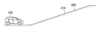
- FIG. 12A is a conceptual diagram showing a situation in which a vehicle is located in front of an ascending slope.
- FIG. 12B is a conceptual diagram showing the user's visual field in the case where the virtual image of the third example of the present invention is projected using the display system described above in the situation where the vehicle is located in front of the upward slope.
- FIG. 11A is a conceptual diagram showing the field of view of the user in the case of projecting the virtual image of the third example of content using the display system described above.
- FIG. 12B is a conceptual diagram showing the user
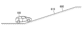
- FIG. 13A is a conceptual diagram showing a situation in which the vehicle is located at the start point of the uphill slope.
- FIG. 13B is a conceptual diagram showing the user's visual field in the case where the virtual image of the third example of the present invention is projected using the display system described above in the situation where the vehicle is located at the slope start point of the upward slope.
- FIG. 14A is a conceptual diagram showing a situation where a car is positioned on the way uphill.
- FIG. 14B is a conceptual diagram showing a user's visual field in the case where the virtual image of the third content example is projected using the display system described above in the situation where the vehicle is located on the way up.
- FIG. 15A is a conceptual diagram showing a field of view of the user in the case of projecting a virtual image (including an auxiliary marker) of the third example of content using the display system of the above.
- FIG. 15B is a conceptual diagram showing the field of view of the user in the case of projecting the partially transmitted virtual image of the third example content using the display system of the above.
- FIG. 16 is a conceptual diagram showing the field of view of the user in the case of projecting the virtual image (sign) of the third example of content using the display system of the above.
- FIG. 17A is a conceptual diagram showing the field of view of the user in the case of projecting the virtual image (name of a road) of the fourth example of content using the display system described above.
- FIG. 17B is a conceptual diagram showing the field of view of the user in the case of projecting a virtual image (name of a road) of the fourth example of content using the display system described above.
- FIG. 18 is a conceptual diagram showing the field of view of the user in the case of projecting the virtual image (the direction of the road) of the fourth example of content using the display system of the above.
- FIG. 19 is a conceptual diagram showing the field of view of the user in the case of projecting the virtual image of the fifth example of content using the display system described above.
- FIG. 20 is a conceptual diagram showing the field of view of the user in the case of projecting the virtual image of the sixth content example using the display system of the above.
- FIG. 21 is a conceptual diagram showing the field of view of the user in the case of projecting the virtual image of the seventh example of content using the display system of the above.
- FIG. 22 is a conceptual diagram showing the field of view of the user in the case of projecting the virtual image of the eighth example content using the display system of the above.
- FIG. 23 is a conceptual diagram showing the field of view of the user in the case of projecting the virtual image of the ninth example of content using the display system described above.
- the driver of the vehicle can grasp the route to the destination, but has a problem that it is difficult to grasp the condition of the road surface on which the vehicle is moving.
- the display system 10 is, for example, a head-up display (HUD) used in an automobile 100 as shown in FIGS. 1 to 3.
- the display system 10 is installed in a cabin of the automobile 100 so as to project an image from below onto the windshield 101 of the automobile 100.
- the display system 10 is disposed in the dashboard 102 below the windshield 101.
- the automobile 100 (moving body) includes the display system 10 and the reflection member (here, the windshield 101).
- the reflective member is light transmissive and reflects light emitted from a projection unit 40 (described later) included in the display system 10.
- the user 200 visually recognizes, through the windshield 101, the virtual image 300 projected on the target space 400 set in front of the vehicle 100 (outside the vehicle).
- virtual image means an image that is formed so that an object is actually present by the diverging rays when light emitted from the display system 10 diverges at a reflecting object such as the windshield 101 or the like. Therefore, the user 200 can see the virtual image 300 projected by the display system 10 superimposed on the real space extending in front of the automobile 100. Therefore, according to the display system 10, various driving support information such as, for example, vehicle speed information, navigation information, pedestrian information, forward vehicle information, lane deviation information, and vehicle condition information are displayed as a virtual image 300, It can be made visible to 200. As a result, the user 200 can visually acquire the driving support information with only a slight line of sight movement from the state where the line of sight is directed to the front of the windshield 101.
- the display system 10 is a part of the information presentation system 1000 as shown in FIG. 2 and acquires from the detection system 7 ADAS information (described later) which is a part of the driving support information. .
- the detection system 7 is configured to detect an object around the vehicle 100.
- the information presentation system 1000 includes the display system 10 and the detection system 7.
- the virtual image 300 formed in the target space 400 includes at least two types of virtual images of the first virtual image 301 and the second virtual image 302, as shown in FIGS. 1 and 3. .
- the “first virtual image” is a virtual image 300 (301) formed on the first virtual surface 501.
- the “first virtual plane” is a virtual plane in which the inclination angle ⁇ with respect to the optical axis 500 of the display system 10 is smaller than a predetermined value ⁇ ( ⁇ ⁇ ).
- the “second virtual image” mentioned here is a virtual image 300 (302) formed on the second virtual surface 502.
- the “second virtual plane” is a virtual plane in which the tilt angle ⁇ with respect to the optical axis 500 of the display system 10 is larger than a predetermined value ⁇ ( ⁇ > ⁇ ).
- the “optical axis” here is an optical axis of an optical system of a projection optical system 4 (see FIG. 2) described later, which means an axis passing through the center of the target space 400 and along the optical path of the virtual image 300.
- the predetermined value ⁇ is 45 degrees as an example, and the inclination angle ⁇ is 90 degrees as an example.
- the virtual image 300 formed in the target space 400 includes the third virtual image 303 (see FIG. 3) in addition to the first virtual image 301 and the second virtual image 302.
- the “third virtual image” is a virtual image 300 (303) formed on the second virtual surface 502 in which the tilt angle ⁇ with respect to the optical axis 500 is larger than the predetermined value ⁇ .
- the virtual image formed by the light transmitted through the movable screen 1a is the second virtual image 302 and is transmitted by the light transmitted through the fixed screen 1b.
- the virtual image formed is the third virtual image 303.
- the optical axis 500 is along the road surface 600 in front of the vehicle 100 in the target space 400 in front of the vehicle 100.
- the first virtual image 301 is formed on a first virtual surface 501 substantially parallel to the road surface 600
- the second virtual image 302 and the third virtual image 303 are on a second virtual surface 502 substantially perpendicular to the road surface 600. It is formed.
- the road surface 600 is a horizontal plane
- the first virtual image 301 is displayed along the horizontal plane
- the second virtual image 302 and the third virtual image 303 are displayed along the vertical plane.
- the first virtual image 301 is different in the distance (also referred to as “visual distance”) from the farthest portion to the farthest portion from the eye (eye point) of the user 200. That is, the first virtual image 301 is a virtual image having a width at the depth in the traveling direction of the mobile object (the automobile 100). In other words, the first virtual image 301 is a virtual image whose depth is different in parallel with the traveling direction of the moving object.
- FIG. 3 is a conceptual view showing the field of view of the user 200.
- the display system 10 of the present embodiment can display the first virtual image 301, the second virtual image 302, and the third virtual image 303.
- the first virtual image 301 is viewed by the user 200 with a depth along the road surface 600.
- the second virtual image 302 and the third virtual image 303 are viewed upright on the road surface 600 at a constant distance from the user 200. Therefore, for the user 200, the first virtual image 301 appears on a plane substantially parallel to the road surface 600, and the second virtual image 302 and the third virtual image 303 are on a plane substantially perpendicular to the road surface 600. looks like.
- the content of the first virtual image 301 is, as an example, information indicating the traveling direction of the vehicle 100 as navigation information, and an arrow indicating right turn or left turn can be presented to the user 200 on the road surface 600 or the like.
- the content of the second virtual image 302 is, as an example, information indicating a distance to a preceding vehicle or a pedestrian, and it is possible to present the distance to the preceding vehicle (inter-vehicle distance) on the preceding vehicle to the user 200 .
- the contents of the third virtual image 303 are, as an example, the current time, vehicle speed information, and vehicle condition information, and for example, the user 200 is presented with information such as letters, numbers, symbols, or a fuel meter. Etc. are possible.
- the content of the virtual image 300 has a width in the traveling direction of the vehicle 100 and includes at least attribute information of the road surface 600 on which the vehicle 100 is traveling. Therefore, it is possible to show the user 200 the condition of the road surface 600 on which the automobile 100 is traveling, etc. by the virtual image 300.
- the “attribute information of the road surface 600” includes information on an object on the road surface 600 as well as information on the road surface 600 itself, such as the slope of the road surface 600 and the name of the road including the road surface 600, for example. .
- the object on the road surface 600 is, for example, another moving object (here, another vehicle) different from the car 100 moving on the road surface 600, an obstacle other than the other moving object on the road surface 600 (eg, a pedestrian , Construction site etc.). Details will be described later in “(4) Content of virtual image”.
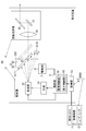
- the display system 10 acquires a plurality of screens 1 a and 1 b, a drive unit 2, an irradiation unit 3, a projection optical system 4, and a control unit 5. And 6 are provided.
- the projection optical system 4 and the irradiation unit 3 constitute a projection unit 40 that projects the virtual image 300 (see FIG. 1) onto the target space 400 (see FIG. 1).
- the plurality of screens 1a and 1b include a stationary screen 1b and a movable screen 1a.
- the fixed screen 1 b is fixed at a fixed position with respect to a housing or the like of the display system 10.
- the movable screen 1 a is inclined at an angle ⁇ with respect to the reference surface 503.
- the movable screen 1a is configured to be movable in a moving direction X (direction shown by an arrow X1-X2 in FIG. 2) orthogonal to the reference surface 503.
- the "reference plane” referred to here is a virtual plane that defines the moving direction of the movable screen 1a, and is not an existing plane.
- the movable screen 1a is configured to be linearly movable in the moving direction X while maintaining the posture inclined by the angle ⁇ with respect to the reference surface 503.
- each of the plurality of screens 1a and 1b may be referred to as "screen 1".
- the screen 1 (each of the movable screen 1a and the fixed screen 1b) has translucency, and forms an image for forming a virtual image 300 (see FIG. 1) in the target space 400 (see FIG. 1). That is, on the screen 1, an image is drawn by the light from the irradiation unit 3, and the light passing through the screen 1 forms a virtual image 300 in the target space 400.
- the screen 1 is made of, for example, a plate-like member having a light diffusing property and formed in a rectangular shape. The screen 1 is disposed between the irradiation unit 3 and the projection optical system 4.
- the drive unit 2 moves the movable screen 1 a in the moving direction X.
- the drive unit 2 can move the movable screen 1 a in both the direction approaching the projection optical system 4 and the direction away from the projection optical system 4 along the moving direction X.
- the drive unit 2 is, for example, an electrically driven actuator such as a voice coil motor, and operates according to a first control signal from the control unit 5.
- the irradiation unit 3 is a scanning-type light irradiation unit, and emits light to the movable screen 1a or the fixed screen 1b.
- the irradiation unit 3 includes a light source 31 and a scanning unit 32. In the irradiation unit 3, each of the light source 31 and the scanning unit 32 operates according to the second control signal from the control unit 5.
- the light source 31 is formed of a laser module that outputs a laser beam.
- the light source 31 includes a red laser diode that outputs red (R) laser light, a green laser diode that outputs green (G) laser light, and a blue laser diode that outputs blue (B) laser light. Contains.
- the laser beams of three colors output from these three types of laser diodes are synthesized by, for example, a dichroic mirror, and enter the scanning unit 32.
- the scanning unit 32 scans the light from the light source 31 to emit light scanning the entire surface of the movable screen 1a or the fixed screen 1b onto the movable screen 1a or the fixed screen 1b.
- the scanning unit 32 performs a raster scan that scans light two-dimensionally on one surface of the movable screen 1a or the fixed screen 1b.
- the projection optical system 4 receives the light output from the irradiation unit 3 and transmitted through the screen 1 as incident light, and projects the virtual image 300 (see FIG. 1) onto the target space 400 (see FIG. 1) by the incident light.
- the projection optical system 4 is arranged in line with the screen 1 in the moving direction X of the movable screen 1 a.
- the projection optical system 4 has a magnifying lens 41, a first mirror 42, and a second mirror 43, as shown in FIG.
- the magnifying lens 41, the first mirror 42, and the second mirror 43 are disposed in this order on the path of light transmitted through the screen 1.
- the magnifying lens 41 is disposed on the side (first direction X1 side) opposite to the irradiation unit 3 in the moving direction X as viewed from the screen 1 so that light output along the moving direction X from the screen 1 is incident It is done.
- the magnifying lens 41 magnifies the image formed on the screen 1 by the light from the irradiating unit 3 and outputs the image to the first mirror 42.
- the first mirror 42 reflects the light from the magnifying lens 41 toward the second mirror 43.
- the second mirror 43 reflects the light from the first mirror 42 toward the windshield 101 (see FIG. 1).
- the projection optical system 4 projects the virtual image 300 on the target space 400 by enlarging the image formed on the screen 1 by the light from the irradiation unit 3 with the magnifying lens 41 and projecting it on the windshield 101.
- the optical axis of the magnifying lens 41 is the optical axis 500 of the projection optical system 4.
- the control unit 5 is configured of, for example, a microcomputer whose main configuration is a CPU (Central Processing Unit) and a memory.
- the control unit 5 is realized by a computer having a CPU and a memory, and the computer functions as the control unit 5 when the CPU executes a program stored in the memory.
- the program is pre-recorded in the memory of the control unit 5, but may be provided through a telecommunication line such as the Internet or in a recording medium such as a memory card.
- the control unit 5 controls display of the virtual image 300 projected on the target space 400 by controlling the drive unit 2 and the irradiation unit 3.
- the control unit 5 controls the drive unit 2 with the first control signal, and controls the irradiation unit 3 with the second control signal. Further, the control unit 5 is configured to synchronize the operation of the drive unit 2 and the operation of the irradiation unit 3. Furthermore, as shown in FIG. 2, the control unit 5 has functions as a drive control unit 51 and a display control unit 52.
- the drive control unit 51 controls the drive unit 2 to move the movable screen 1 a relative to the reference position.
- the “reference position” mentioned here is a position set at a specified position in the movement range of the movable screen 1 a.
- the drive control unit 51 moves the movable screen 1 a to project the first virtual image 301 and the second virtual image 302 to the target space 400 by the light transmitted through the movable screen 1 a, and the irradiation unit 3 moves the movable screen 1 a to the movable screen 1 a.
- the drive unit 2 is controlled in synchronization with the drawing.
- the display control unit 52 cooperates with the drive control unit 51 to display the virtual image 300 of the content based on the one or more pieces of information (also referred to as “moving object information”) acquired from the acquisition unit 6.
- the irradiation unit 3 is controlled.
- the virtual image 300 (here, the first virtual image 301) has a width in the traveling direction of the vehicle 100 (moving object), and includes at least content representing attribute information of the road surface 600 on which the vehicle 100 is moving. It is.
- the acquisition unit 6 includes information on the position of the automobile 100 (moving object) (also referred to as “position information”), information on objects around the automobile 100 (also referred to as “ADAS information”), and information on the state of the automobile 100 (“ “Vehicle information” (also referred to as “vehicle information”) is acquired. That is, the attribute information included in the content of the virtual image 300 is information based on one or more of the position information, the ADAS information, and the vehicle information.
- the ADAS information is information that can be detected by a camera that is a detection unit of an advanced driver assistance system (ADAS: Advanced Driver Assistance System), a sonar sensor, a radar, a LiDAR (Light Detection and Ranging), and the like.
- ADAS Advanced Driver Assistance System
- the acquisition unit 6 acquires ADAS information from the detection system 7 provided with the imaging device 71 and the laser radar 72.
- the imaging device 71 captures a space around the vehicle 100 including the target space 400.
- the laser radar 72 measures the distance from an object present in the space around the vehicle 100 to the vehicle 100, the nature of the object, and the like.
- ADAS information As a specific example of ADAS information, the distance from the moving object to the vehicle moving around the automobile 100, the relative coordinates of this vehicle with respect to the automobile 100, the inter-vehicle distance between a plurality of vehicles, the relative speed of these vehicles, etc. There is.
- objects in the vicinity of the vehicle 100 in the ADAS information include vehicles running or stopping around the vehicle 100, structures such as guard rails, pedestrians, small animals, and the like.
- the vehicle information is information that represents the local state of the vehicle 100 itself, and is information that can be detected by a sensor mounted on the vehicle 100.
- vehicle information include the moving speed of the automobile 100 (traveling speed), the acceleration applied to the automobile 100, the depression amount of the accelerator pedal (accelerator opening degree), the depression amount of the brake pedal, the steering angle, and the inclination of the vehicle. There is inclination of the seat in the vehicle and the like.
- the driver's pulse detected by the driver monitor, the expression, the line of sight, and the like are also included in the vehicle information.
- data specific to the automobile 100 such as vehicle width, vehicle height, total length, and eye point, is also included in the vehicle information.
- Position information is information based on the position of the automobile 100, and is information that can be detected using a positioning system such as GPS (Global Positioning System), such as road information at the position of the vehicle.
- GPS Global Positioning System
- Specific examples of the position information include the number of lanes of the road at the vehicle position, whether it is an intersection, whether it is a double road, whether it is one way, road width, presence of sidewalks, slope, curvature of curve, etc. .
- the control unit 5 controls the irradiating unit 3 to irradiate light from the irradiating unit 3 to the movable screen 1 a.
- light that scans one surface of the movable screen 1 a is emitted from the irradiation unit 3 to the movable screen 1 a.
- an image is formed (projected) on the movable screen 1a.
- the light from the irradiation unit 3 passes through the movable screen 1 a and is irradiated from the projection optical system 4 to the windshield 101.
- the image formed on the movable screen 1 a is projected onto the windshield 101 from the lower side of the windshield 101 in the cabin of the automobile 100.
- the windshield 101 When an image is projected from the projection optical system 4 to the windshield 101, the windshield 101 reflects the light from the projection optical system 4 toward the user 200 (driver) in the vehicle interior. Thereby, the image reflected by the windshield 101 is visually recognized by the user 200. As a result, the user 200 can visually recognize the virtual image 300 (the first virtual image 301 or the second virtual image 302) projected to the front (outside the vehicle) of the automobile 100 through the windshield 101.
- the control unit 5 causes the light to scan on one surface of the movable screen 1 a in a state in which the movable screen 1 a is fixed in the moving direction X, thereby being viewed by the user 200 with depth along the road surface 600.
- the first virtual image 301 is formed.
- the control unit 5 scans light on one surface of the movable screen 1a. Let As a result, a second virtual image 302 that is viewed upright on the road surface 600 at a certain distance from the user 200 is formed.
- control unit 5 controls the drive unit 2 to move the movable screen 1 a in the moving direction X in a period in which light is emitted from the irradiation unit 3 to the movable screen 1 a. From the eye (eye point) of the user 200 to the virtual image 300 when the movable screen 1a moves in the first direction X1 when the irradiation position of light from the irradiation unit 3 on one surface of the movable screen 1a, that is, the position of the bright spot is the same.
- the visual distance of is short.
- the visual distance to the virtual image 300 becomes long (far). That is, the viewing distance to the virtual image 300 changes with the position of the movable screen 1 a in the moving direction X.
- the control unit 5 moves the movable screen 1a in the X direction according to the visual distance, and fixes the movable screen 1a at the position after movement. Light is scanned on one surface of the movable screen 1a.
- the control unit 5 moves the movable screen 1a in the X direction according to the viewing distance. The control unit 5 scans light on one surface of the movable screen 1a while moving the movable screen 1a so that the distance in the X direction from the bright spot to the projection optical system 4 becomes constant based on the position after movement
- control unit 5 controls the irradiating unit 3 to irradiate light from the irradiating unit 3 to the fixed screen 1 b. At this time, light which scans one surface of the fixed screen 1 b is emitted from the irradiation unit 3 to the fixed screen 1 b.
- an image is formed (projected) on the fixed screen 1 b and the image is projected on the windshield 101.
- the user 200 can visually recognize the virtual image 300 (third virtual image 303) projected to the front (outside of the vehicle) of the automobile 100 through the windshield 101.
- the third virtual image 303 is formed of light projected onto the fixed screen 1b whose position is fixed, the third virtual image 303 is on the road surface 600 at a predetermined distance (for example, 2 to 3 m) from the user 200. It is viewed upright.
- the two virtual images 302 and the third virtual image 303 can all be projected.
- the movable screen 1a is irradiated with light to project the first virtual image 301, and then the fixed screen
- the third virtual image 303 is projected by emitting light to 1b.
- the fixed screen 1b is irradiated with light to project the third virtual image 303, and then the light is projected on the movable screen 1a To project the second virtual image 302.
- the first virtual image 301, the third virtual image 303, and the second virtual image 302 are projected on the target space 400 during one cycle in which the scanning unit 32 scans in the vertical direction. Since the scanning in the vertical direction in the irradiation unit 3 is performed at relatively high speed, the user 200 visually recognizes the first virtual image 301, the third virtual image 303, and the second virtual image 302 as being simultaneously displayed.
- the frequency of scanning in the vertical direction in the irradiation unit 3 is, for example, 60 Hz or more.
- the virtual image 300 includes a marker 310 as shown in FIG.
- a marker 310 is a first virtual image 301, and represents a predicted path of the automobile 100 (moving object).
- the “predicted route” is a route that is predicted to be traveled by the vehicle 100 when the user 200 maintains the current steering wheel operation.
- the marker 310 is shaped so as to avoid the other vehicle 110 in the specific area A1 (see the broken line in FIG. 4 and similarly in FIG. 5).
- the boundary with the other vehicle 110 in the specific area A1 is a relatively thick line.
- the specific area A1 is an area that is in the traveling direction of the automobile 100 and the predicted route overlaps with the other automobile 110.
- specific area A1 is a shape which avoids other motor vehicles 110 as mentioned above, and the border line with other motor vehicles 110 becomes a comparatively thick line, and motor vehicle 100 can not enter specific area A1. It shows that it is possible. That is, in the present embodiment, the attribute information of the virtual image 300 is information indicating whether or not the vehicle 100 can enter the specific area A1 in the traveling direction of the vehicle 100.
- the virtual image 300 is displayed, for example, when the road surface 600 satisfies the predetermined criteria.
- the predetermined standard is satisfied, for example, when the road surface 600 is a narrow section, a construction site exists, or the like, and a plurality of vehicles can not travel side by side.
- the control unit 5 is a marker of the content representing a recommended route by which the vehicle 100 can avoid the specific area A1.
- 311 (virtual image 300) is displayed.
- the control unit 5 acquires one or more pieces of moving body information (for example, road information at the vehicle position, object information around the vehicle, etc.) from the acquisition unit 6 (step S101). Then, the control unit 5 constructs a pseudo space (virtual 3D space) imitating the target space 400 based on the acquired one or more pieces of moving body information (step S102).
- a pseudo space virtual 3D space
- step S103 determines whether the road surface 600 on which the automobile 100 is traveling satisfies the predetermined standard.
- step S103 determines whether the road surface 600 on which the automobile 100 is traveling satisfies the predetermined standard.
- step S103: No the control unit 5 does not perform the subsequent processing and executes step S101 again because the road surface 600 is not a narrow section.
- step S103: Yes the control unit 5 determines one or more pieces of mobile object information (for example, vehicle width, steering angle, direction information, etc.) acquired from the acquisition unit 6 , Draw a predicted path in the pseudo space (step S104).
- mobile object information for example, vehicle width, steering angle, direction information, etc.
- the control unit 5 determines whether an object is present on the predicted path (step S105). If an object (for example, another automobile 110) exists on the predicted path (step S105: Yes), the control unit 5 draws entry impossibility information in the pseudo space (step S106). The entry disallowed information is information representing that the vehicle 100 can not enter the specific area A1. Then, when there is a path that can avoid the object, the control unit 5 draws a recommended path in the pseudo space (step S107). After that, the control unit 5 controls the drive unit 2 and the irradiation unit 3 to project the content drawn in the pseudo space as the virtual image 300 on the target space 400 (step S108). Thereby, the marker 310 representing the predicted route and the marker 311 representing the recommended route are projected onto the road surface 600 in the target space 400.
- step S105 determines whether an object exists in the target space 400 (step S109).
- step S109 determines whether an object exists in the target space 400 (step S109: Yes).
- step S109 executes the step S108 after drawing the recommended route in the pseudo space (step S107).
- step S109 executes step S108 without drawing the recommended route in the pseudo space.
- step S109 The situation in which the process of step S109 is performed will be described.
- the predicted path changes.
- the predicted path substantially matches the recommended path, no object is present on the predicted path.
- the marker 311 continues to be projected to the target space 400.
- an object does not exist in the target space 400, for example, when the car 100 passes by the side of another car 110, the marker 311 is not projected to the target space 400.
- a virtual image 300 of content representing whether the vehicle 100 can enter the specific area A1 in the traveling direction of the vehicle 100 is projected onto the target space 400. Therefore, there is an advantage that it is easy for the user 200 to easily determine whether it is necessary to change the traveling direction of the vehicle 100 by visually recognizing the virtual image 300. Further, in the present content example, when the vehicle 100 can not enter the specific area A1, the virtual image 300 of the content representing the avoidance route is projected to the target space 400. For this reason, there is an advantage that it is easy for the user 200 to select the avoidance of the specific area A1 which can not be entered by the user 200 visually recognizing the virtual image 300.
- the processing of steps S101 and S102 may be performed after the processing of step S103, not before the processing of step S103.
- the processes of steps S101 and S102 are performed only when the road surface 600 matches the predetermined standard.
- the color of the specific area A1 in the marker 310 may be different from that of the part other than the specific area A1 if the vehicle 100 can not enter the specific area A1. In this aspect, it is easy for the user 200 to perceive that the automobile 100 can not enter the specific area A1.
- control unit 5 may project the virtual image 300 of the content representing the stop of the vehicle 100 onto the target space 400 when there is no route capable of avoiding the object. In this aspect, it is easy for the user 200 to perceive that the vehicle 100 should be stopped.
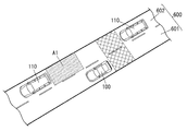
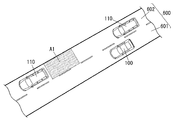
- FIGS. 7A and 7B show the virtual image 300 from the first lane 601 where the automobile 100 (moving object) is traveling to another lane 602. It is projected onto the target space 400 in a lane change situation.
- FIG. 7A shows the state of the road surface 600 where the vehicle 100 can change lanes without acceleration or deceleration.
- FIG. 7B shows the situation of the road surface 600 where the other automobile 110 runs parallel to the automobile 100 and the lane can not be changed unless the automobile 100 accelerates.
- a virtual image 300 composed of two markers 312 and 313 is projected onto the target space 400 as shown in FIG.
- a marker 312 is a first virtual image 301 and represents a specific area A1 in a second lane 602 different from the first lane 601 in which the vehicle 100 is traveling.
- the specific area A1 changes color (or shape) depending on whether the vehicle 100 can enter (that is, lane change is possible) or not.
- a marker 313 is a first virtual image 301 and represents a plurality of (here, two) arrows for prompting the user 200 to change the lane.
- the marker 313 is projected to the target space 400 only when the vehicle 100 can enter.
- the control unit 5 when the user 200 operates the turn signal, the control unit 5 is based on one or more pieces of mobile object information (for example, vehicle speed, object information around the vehicle, etc.) acquired from the acquisition unit 6. Then, it is determined whether the vehicle 100 can enter the specific area A1.
- the control unit 5 also uses detection information from a BSM (Blind Spot Monitor) system as one piece of mobile object information.
- BSM Breast Spot Monitor
- the shaded lines in FIG. 7A represent the detection area of the BSM system.
- a virtual image 300 consisting of three markers 312, 313, 314 is projected onto the target space 400.
- a marker 314 is a first virtual image 301 and represents a plurality of (here, three) arrows for urging the user 200 to accelerate or decelerate (here, acceleration).
- the control unit 5 accelerates or decelerates the vehicle 100 based on the one or more pieces of mobile object information acquired from the acquisition unit 6, and thereby the specific area A1. It is judged whether or not it is possible to enter.
- the control unit 5 uses, for example, information such as a vehicle speed, object information around the own vehicle, and a relative velocity with another vehicle 110 as the moving body information.
- the control unit 5 may use detection information from the BSM system.
- the attribute information of the virtual image 300 is information indicating whether or not the vehicle 100 can enter the specific area A1 in the traveling direction of the vehicle 100. Further, in the present content example, the specific area A1 is in a lane (second lane 602) different from the lane (first lane 601) in which the vehicle 100 travels.
- the control unit 5 acquires one or more pieces of mobile object information from the acquisition unit 6 (step S201). Then, the control unit 5 constructs a pseudo space (virtual 3D space) imitating the target space 400 based on the acquired one or more pieces of moving body information (step S202).
- a pseudo space virtual 3D space
- control unit 5 determines whether the direction indicator is in operation (step S203). If the turn signal indicator is not in operation (No at Step S203), the user 200 does not have the intention to change the lane, and the control unit 5 again executes Step S201 without performing the subsequent processing. On the other hand, when the turn indicator is in operation (step S203: Yes), the control unit 5 determines the specific area A1 that can enter the second lane 602 based on the one or more pieces of mobile object information acquired from the acquisition unit 6. Is determined (step S204).
- step S204 If the specific area A1 accessible to the second lane 602 is present (step S204: Yes), the control unit 5 draws the specific area A1 accessible to the second lane 602 of the pseudo space (step S205). In addition, the control unit 5 draws information for prompting a lane change in the first lane 601 of the pseudo space (step S206). After that, the control unit 5 controls the drive unit 2 and the irradiation unit 3 to project the content drawn in the pseudo space as the virtual image 300 on the target space 400 (step S207). As a result, in the target space 400, the marker 312 representing the specific area A1 is projected to the second lane 602, and the marker 313 for prompting a lane change is projected to the first lane 601.
- step S04 determines whether the specific area A1 accessible can be generated by acceleration or deceleration of the vehicle 100. It judges (step S208).
- step S208 determines whether the specific area A1 accessible can be generated by acceleration or deceleration of the vehicle 100. It judges (step S208).
- step S208: Yes the control unit 5 draws the specific area A1 that can enter the second lane 602 of the pseudo space (step S209). Further, the control unit 5 draws information for prompting a lane change in the first lane 601 of the pseudo space and information for prompting acceleration or deceleration (step S210).
- control unit 5 controls the drive unit 2 and the irradiation unit 3 to project the content drawn in the pseudo space as the virtual image 300 on the target space 400 (step S207).
- the marker 312 representing the specific area A1 is projected to the second lane 602
- the marker 313 for prompting lane change, and the marker 314 for prompting acceleration or deceleration are projected to the first lane 601 .
- step S208 when the entryable specific area A1 does not occur (step S208: No), the control unit 5 draws entry impossibility information in the pseudo space (step S211).
- the entry impossibility information is information indicating that the vehicle 100 can not enter the specific area A1 (that is, it can not change lanes).
- the control unit 5 controls the drive unit 2 and the irradiation unit 3 to project the content drawn in the pseudo space as the virtual image 300 on the target space 400 (step S207). Thereby, in the target space 400, the marker 312 representing the inaccessible specific area A1 is projected to the second lane 602.
- a virtual image 300 of content that indicates whether the vehicle 100 can enter the specific area A1 in the second lane 602 is projected onto the target space 400. Therefore, by visually recognizing the virtual image 300, the user 200 can easily determine whether to change the lane.
- the processes of steps S201 and S202 may be performed after the process of step S203, not before the process of step S203. In this case, the processes of steps S201 and S202 are performed only when it is determined that the turn signal is operating.
- virtual image 300 of this example of contents may be projected on object space 400, for example in the situation which parks car 100 on a road shoulder. This is because when the automobile 100 is to be parked on the road shoulder, the user 200 operates the turn signal as in the case of the lane change. In this case, the specific area A1 is not on the second lane 602 but on the shoulder of the first lane 601.
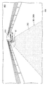
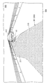
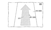
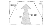
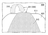
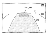
- the virtual image 300 is composed of the marker 315 as shown in FIGS. 11A and 11B.
- a marker 315 is a first virtual image 301 in the form of an arrow, and represents the slope of the road surface 600 on which the vehicle 100 (moving object) is traveling.
- the marker 315 has a shape in which the shaft of the arrow is tapered from the near side to the far side, and has a character string of “UP”.
- the marker 315 indicates that the road surface 600 is an upward slope 610.
- the marker 315 is shaped such that the shaft of the arrow becomes thicker as it goes from the near side to the far side, and has a character string of "DOWN”.
- the marker 315 indicates that the road surface 600 has a downward slope 611. That is, in the present content example, the attribute information of the virtual image 300 is information representing the gradient of the road surface 600 on which the vehicle 100 is moving.
- the virtual image 300 is displayed, for example, from when the vehicle 100 is located in front of the slope until it reaches the road surface 600 without the slope.
- the control unit 5 uses the marker 315 as the target space 400 based on one or more pieces of mobile object information (for example, road information at the vehicle position, vehicle speed, inclination of the vehicle, etc.) acquired from the acquisition unit 6.
- the display of the virtual image 300 is controlled so as to be superimposed and projected on the road surface 600 at the position.
- the virtual image 300 of the content representing the slope of the road surface 600 on which the vehicle 100 is traveling is projected onto the target space 400. Therefore, the user 200 has an advantage of easily grasping whether the road surface 600 is the upward slope 610 or the downward slope 611 by visually recognizing the virtual image 300, and performing the driving according to the slope of the road surface 600 easily.
- the virtual image 300 of this example of content is effective, for example, when it is difficult for the user 200 to notice that there is a gradient due to the structure or scenery of the road surface 600.
- the vehicle 100 may naturally decelerate, leading to traffic congestion.
- the distance between the vehicle 100 and another vehicle ahead may be narrowed more than necessary due to the vehicle 100 accelerating naturally. There is. Even in such a case, the user 200 can perform appropriate acceleration or deceleration by visually recognizing the virtual image 300.
- the marker 315 shown to FIG. 11A and 11B has the character string of "UP” and “DOWN", respectively, it is not the meaning limited to this.
- none of the markers 315 shown in FIGS. 11A and 11B may have a character string.
- the marker 315 shown to FIG. 11A and 11B may be comprised with a moving image instead of a still image.
- the marker 315 illustrated in FIG. 11A may be a moving image that waves toward the near side as time passes.
- the marker 315 illustrated in FIG. 11B may be a moving image that waves back toward the back side with the passage of time.
- the attribute information of the virtual image 300 preferably changes according to the position of the vehicle 100 relative to the slope. Specifically, based on the one or more pieces of mobile object information acquired from the acquisition unit 6, the control unit 5 calculates in advance the inclination of the road surface 600 in front and the coordinates at which the inclination changes. Then, using the calculated coordinates as a starting point, the control unit 5 changes the shape of the marker 315 (here, the shape of the shaft of the arrow) according to the inclination angle of the gradient.
- FIG. 12A when the vehicle 100 approaches the upward slope 610, a marker 315 as shown in FIG. 12B is projected onto the target space 400.
- this marker 315 the width of the arrow shaft and the rate of change in width of the arrow are different between the marker 315A on the front side and the marker 315B on the back side, with the start position of the upward slope 610 as a boundary.
- FIGS. 13A and 14A when the vehicle 100 starts traveling on the up slope 610, the markers 315 as shown in FIGS. 13B and 14B are projected onto the target space 400. In these markers 315, as the inclination of the automobile 100 approaches the inclination angle of the upward slope 610, the width of the shaft of the arrow is narrowed.
- the user 200 recognizes that the slope is before the vehicle 100 reaches the slope by visually recognizing the virtual image 300. It is possible. Further, in this configuration, there is an advantage that the user 200 can easily drive while recognizing the inclination of the road surface 600 by recognizing the virtual image 300.
- the auxiliary marker 316 may be projected onto the target space 400 in addition to the marker 315.
- the auxiliary marker 316 is a first virtual image 301, and has an arrow shape that describes an arch that is convex upward.
- the auxiliary marker 316 indicates that the road surface 600 has a downward slope 611. In this case, by visually recognizing not only the marker 315 but also the auxiliary marker 316, there is an advantage that the gradient of the road surface 600 can be more intuitively recognized.
- the marker 315 is projected onto the target space 400 in such a manner that a part is seen through by changing a part of the transmittance or color. It is also good.
- the portion of the marker 315 extending to the downward slope 611 is represented as being transmitted through the road surface 600. Also in this case, the visual recognition of the marker 315 by the user 200 is advantageous in that the gradient of the road surface 600 can be more intuitively recognized.
- the arrow-shaped marker 315 is projected as the virtual image 300 onto the target space 400, but the present invention is not limited thereto.
- a marker 315 of a marker representing the speed limit on the road surface 600 (here, 50 km / hr) may be projected onto the target space 400 as a virtual image 300.
- the user 200 has an advantage that it is easy to recognize two pieces of information: the slope of the road surface 600 and the speed limit on the road surface 600.
- the marker 315 may be configured by, for example, an icon other than a sign, or may be configured by a character string such as “with gradient”. That is, the marker 315 may be at least an aspect that represents the slope of the road surface 600.
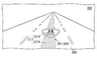
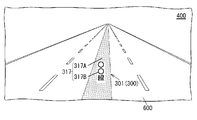
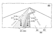
- the virtual image 300 is configured of a marker 317 including two markers 317A and 317B.
- a marker 317A is a first virtual image 301, and represents a predicted path of the automobile 100 (moving object).
- the marker 317B is the first virtual image 301 and represents the name of the road on which the vehicle 100 is traveling (here, the national route ⁇ ), and is projected on the marker 317A. That is, in the present content example, the attribute information of the virtual image 300 is information representing the name of a road including the road surface 600 on which the automobile 100 is moving.
- the virtual image 300 is always displayed, for example, while the automobile 100 is in operation.
- the control unit 5 sets the marker 317 on the road surface 600 in the target space 400 based on one or more pieces of mobile object information (for example, a steering angle, road information at the vehicle position, etc.) acquired from the acquisition unit 6.
- the display of the virtual image 300 is controlled to be superimposed and projected.
- the virtual image 300 of content representing the name of the road on which the vehicle 100 is traveling is projected onto the target space 400. Therefore, by visually recognizing the virtual image 300, the user 200 has an advantage that it is easy to drive while grasping where it is heading.
- the name of the road represented by the marker 317B is a national road, but it may be a prefectural road, a prefectural road, a city road or the like. Further, in the present content example, the name of the road represented by the marker 317B may be, for example, a line (here, an ⁇ line) as shown in FIG. 17B, a streak, a street, a highway, a bypass, etc. It is also good.
- the marker 317B may represent the direction in which the vehicle 100 is traveling (here, ⁇ direction), as shown in FIG. 18, for example. That is, in the present content example, the attribute information of the virtual image 300 may be information indicating the direction of the road including the road surface 600 on which the automobile 100 is moving. In this case, not only the marker 317 representing the direction of the lane in which the vehicle 100 is traveling (the first lane 601) but also the marker 317 representing the direction (here, the XX direction) of the other lane (the second lane 602) May also be projected to the target space 400.
- the virtual image 300 is composed of a plurality of (here, three) markers 318 as shown in FIG. 19 and is a moving image.
- the plurality of markers 318 are not the first virtual image 301 having a width in the traveling direction of the vehicle 100, but a second virtual image 302 viewed upright on the road surface 600 at a certain distance from the user 200. is there.
- the virtual image 300 is viewed by the user 200 as an image having a width in the traveling direction of the automobile 100 as a whole by the plurality of markers 318 being projected on the target space 400 as a moving image. .
- the marker 318 located at the foremost position is referred to as “marker 318A”
- the marker 318 located at the farthest end is referred to as “marker 318C”
- the marker located between markers 318A and 318C is referred to as “marker 318B”.
- the virtual image 300 is projected to the target space 400 when the vehicle 100 enters in front of the curve 603 having a curvature equal to or greater than a predetermined value.
- the control unit 5 determines whether or not the curve 603 exists in front of the automobile 100 based on the one or more pieces of mobile body information (for example, road information at the vehicle position) acquired by the acquisition unit 6. to decide. Then, when the control unit 5 determines that the curve 603 exists in front of the automobile 100, the virtual image is projected so that the three markers 318 are projected above the curve 603 in the target space 400 (above the guardrail in FIG. 19). Control 300 displays.
- the three markers 318 are all projected to the target space 400 as an icon including a figure of an arrow pointing to the left.
- the three markers 318 are all projected onto the target space 400 as icons containing the shape of the arrow pointing to the right.
- the control unit 5 sets the virtual image 300 so that three markers 318 are projected in the order of the marker 318A, the marker 318B, the marker 318C, the marker 318A,... At predetermined intervals (for example, one frame to several frames). Control the display. In addition, the three markers 318 move to the target space 400 so that the icon moves to the left and the size of the icon decreases as the distance from the vehicle 100 increases (that is, as the viewing distance increases). It is projected. Thus, at the user 200, the three markers 318 are viewed as moving smoothly along the curve 603.
- the virtual image 300 is projected as a moving image on the target space 400. Therefore, by visually recognizing the virtual image 300, the user 200 has an advantage that it is easy to drive while intuitively grasping the change in the depth of the road surface 600, the curvature of the curve 603, and the direction of the curve 603.
- the virtual image 300 is effective at night at which the user 200 is less likely to grasp the sense of distance than at daytime. That is, even when the user 200 does not notice the presence of the curve 603 because the front is dark, the user 200 can notice the presence of the curve 603 by visually recognizing the virtual image 300.
- the virtual image 300 is a moving image, it is possible to project a plurality of markers 318 one frame at a time.
- the display system 10 is configured to simultaneously project a plurality of markers 318 into one frame, there is a possibility that the display system 10 can not be mounted on the automobile 100 because the volume of the display system 10 is large.
- the display system 10 is configured to project the plurality of markers 318 one by one in one frame, the volume of the display system 10 does not easily increase, and as a result, can not be mounted on the automobile 100
- the sex can be reduced.
- the user 200 can easily gaze at the condition of the road surface 600 represented by the virtual image 300 as compared with the case where the virtual image 300 is a still image.
- the virtual image 300 is projected above the curve 603 in the target space 400 in this example of content, it is not the meaning limited to this.
- the virtual image 300 may be projected so as to be superimposed on the road surface 600 in the target space 400.
- the plurality of markers 318 may be projected onto the target space 400 as the first virtual image 301.
- the virtual image 300 includes two markers 319A and 319B.
- each of the two markers 319A and 319B may be referred to as a "marker 319".
- a marker 319A is a first virtual image 301, and is another road surface 604 connected to the road surface 600 on which the vehicle 100 (moving object) is traveling, and represents another road surface 604 to which the vehicle 100 can enter.
- the other road surface 604 is an entrance of a freeway.
- the marker 319B is a second virtual image 302 and represents the destination of another road surface 604 indicated by the marker 319A.
- the marker 319B is an icon schematically representing a highway, and is projected on the marker 319A in an overlapping manner.
- the attribute information of the virtual image 300 is information representing another road surface 604 to which the vehicle 100 can enter, among the other road surfaces 604 connected to the road surface 600 on which the vehicle 100 is moving. Therefore, although not shown in FIG. 20, even on the other road surface 604 connected to the road surface 600, the marker 319 is on the other road surface 604 (for example, a one-way road surface) to which the vehicle 100 can not enter. Is not projected.
- the virtual image 300 is always displayed, for example, while the automobile 100 is in operation.
- the control unit 5 superimposes the marker 319 on another road surface 604 in the target space 400 based on one or more pieces of mobile object information (for example, road information at the vehicle position, etc.) acquired from the acquisition unit 6. Control the display of the virtual image 300 so as to be projected.
- the virtual image 300 of content representing another accessible road surface 604 connected to the road surface 600 on which the automobile 100 is traveling is projected to the target space 400. Therefore, there is an advantage that the user 200 can easily drive by visually recognizing the virtual image 300 while considering another route different from the current route of the automobile 100. For example, when the user 200 recognizes that there is an entrance of a freeway by visually recognizing the virtual image 300, it is possible to select a route, such as whether to travel on a general road or travel on a freeway. is there.
- another road surface 604 to which the vehicle 100 can enter is, for example, an entrance of a parking lot, an entrance of a store, or the like.
- the marker 319B indicating the destination of another road surface 604 to which the vehicle 100 can enter is projected to the target space 400, but the marker 319B may not be projected.
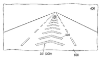
- the virtual image 300 is composed of a plurality of markers 320 as shown in FIG.
- Each of the plurality of markers 320 is projected onto the target space 400 as an arrow directed along the traveling direction of the automobile 100 (mobile body).
- the plurality of markers 320 may cause visual illusion by the user 200 to cause the illusion that the user 200 is accelerating, and may cause the illusion to the user 200 that the vehicle speed of the automobile 100 is faster than the actual vehicle speed. That is, in the present content example, the content of the virtual image 300 is information that causes the user 200 driving the automobile 100 to be considered to be accelerating.
- the virtual image 300 is displayed, for example, when the vehicle speed of the automobile 100 exceeds a threshold speed (here, the speed limit of the road on which the automobile 100 is traveling).
- the control unit 5 sets a plurality of markers 320 in the target space 400 based on one or more pieces of mobile object information (for example, road information at the vehicle position, the vehicle speed of the vehicle, etc.) acquired from the acquisition unit 6.
- the display of the virtual image 300 is controlled so as to be superimposed and projected on the road surface 600 at the position.
- the virtual image 300 which causes the user 200 to be considered as accelerating is projected onto the target space 400. Therefore, by visually recognizing the virtual image 300, the user 200 recognizes that the current vehicle speed is too fast, and tries to lower the current vehicle speed by, for example, stepping on the brake. That is, according to the present embodiment, it is possible to prompt the user 200 to suppress the current vehicle speed to the speed limit or less by making the user 200 visually recognize the virtual image 300.
- the vehicle 100 when the vehicle 100 is provided with a configuration to emit a warning sound when the speed limit is exceeded, the user 200 may feel uncomfortable due to the frequent generation of the warning sound.
- the possibility of giving a sense of discomfort to the user 200 can be reduced by displaying the virtual image 300 instead of the warning sound.
- a paint may be applied to make the user 200 think that the user 200 is accelerating, but the place where such paint is applied is limited.
- the virtual image 300 is not limited to the plurality of markers 320 described above, and may be in another aspect. In other words, the virtual image 300 may be in any mode as long as it allows the user 200 to have an illusion of acceleration.
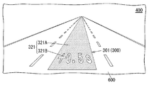
- the virtual image 300 is composed of a marker 321 composed of two markers 321A and 321B.
- a marker 321A is a first virtual image 301, and represents a past route on which the vehicle 100 (moving object) actually travels.
- the departure position and the destination position are the same for the current route and the past route, and the road on which the vehicle 100 travels is the same, for example, a circuit, a route through commuting, and the like.
- the marker 321B is the first virtual image 301, and represents the difference between the time taken for the current route from the departure position to the current position and the time taken for the past route.
- the marker 321B formed of the character string "+0.5 s" is projected on the marker 321A in an overlapping manner. That is, in the present content example, the content of virtual image 300 represents the past route where the current vehicle 100 travels the same position as the departure position and the destination position, and the road on which vehicle 100 travels is the same. It is information.
- the virtual image 300 is displayed, for example, from the start of driving of the automobile 100.
- the control unit 5 records the shortest past route of the required time from the departure position to the destination position among the past routes. Then, when the driving of the automobile 100 is started, the control unit 5 controls the display of the virtual image 300 so that the marker 321A is projected in a superimposed manner on the road surface 600 in the target space 400.
- the information included in the marker 321A is information based on one or more pieces of mobile object information (for example, road information at the vehicle position, etc.) acquired from the acquisition unit 6.
- control unit 5 compares in real time the time taken for the current route from the departure position to the current position and the time taken for the past route so that the marker 321B is projected so as to overlap the marker 321A. , Control the display of the virtual image 300. Thereafter, when the vehicle 100 reaches the target position, if the time taken for the current route from the departure position to the target position is shorter than the time taken for the route in the past, the control unit 5 takes the current route to the past route. Record as
- the virtual image 300 of the content representing the past route is projected onto the target space 400.
- the user 200 can drive while searching for the optimal route to the target position by visually recognizing the virtual image 300 and comparing the current route with the past route. It has the advantage of being possible.
- the display system 10 does not have to project the virtual image 300 of the present content example onto the target space 400.
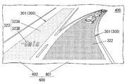
- the virtual image 300 is configured of a marker 322 and a marker 323 formed of two markers 323A and 323B.
- a marker 322 is a first virtual image 301 and represents the current guidance route by the navigation system.
- a marker 323A is the first virtual image 301, and represents the guide route after the re-searching by the navigation system.
- the marker 323B is the first virtual image 301, and represents the difference between the time estimated to be required for the current guide route from the current position to the target position and the time estimated to be required for the guide route after re-searching. There is.
- the virtual image 300 is displayed when the user 200 re-searches the guide route to the target position by the navigation system, for example, when congestion occurs in the current guide route.
- the control unit 5 causes the markers 321 and 322 to be projected on the road surface 600 based on one or more pieces of mobile object information (for example, road information at the vehicle position, etc.) acquired from the acquisition unit 6.
- the marker 321 is projected on the first lane 601 on which the traffic congestion occurs in the road surface 600
- the marker 322 is projected on the second lane 602 branched from the first lane 601.
- the virtual image 300 of the content representing the current guide route and the guide route after the re-search is It is projected.
- the user 200 visually recognizes the virtual image 300 and compares the current guidance route with the guidance route after re-searching, thereby the merit (or disadvantage) of the guidance route after the user 200 searching again.
- the above embodiment is only one of various embodiments of the present disclosure.
- the above embodiment can be variously modified according to the design and the like as long as the object of the present disclosure can be achieved.
- the same function as that of the display system 10 may be embodied by a control method of the display system 10, a computer program, a recording medium recording the program, or the like.
- the control method of the display system 10 is a control method of the display system 10 including the projection unit 40 and the control unit 5.
- the projection unit 40 projects the virtual image 300 on the target space 400.
- the control unit 5 controls the display of the virtual image 300.
- the control method of the display system 10 displays a virtual image 300 of a content having a width in the traveling direction of the moving object (here, the automobile 100) and at least indicating attribute information of the road surface 600 on which the moving object is moving.
- a program according to an aspect is a program for causing a computer system to execute the control method of the display system 10 described above.
- An execution subject of the display system 10 or the control method in the present disclosure includes a computer system.
- the computer system mainly includes a processor and memory as hardware.
- the processor executes the program stored in the memory of the computer system to implement a function as an execution subject of the system or method in the present disclosure.
- the program may be pre-recorded in the memory of the computer system, but may be provided through a telecommunication line. Also, the program may be provided by being recorded in a non-transitory recording medium such as a memory card readable by a computer system, an optical disk, a hard disk drive and the like.
- a processor of a computer system is configured with one or more electronic circuits including a semiconductor integrated circuit (IC) or a large scale integrated circuit (LSI).
- the plurality of electronic circuits may be integrated into one chip or may be distributed to a plurality of chips.
- the plurality of chips may be integrated into one device or may be distributed to a plurality of devices.
- control unit 5 of the display system 10 may be distributed to a plurality of systems (devices).
- at least part of the functions of the control unit 5 may be realized by a cloud (cloud computing).
- the display system 10 communicates directly between a vehicle and a vehicle (between vehicles) or between a vehicle and an infrastructure such as traffic lights and road signs (between roads and vehicles), so-called V2X (Vehicle The communication technology of “everything” may be used.
- V2X communication technology for example, the vehicle 100 can acquire mobile object information from surrounding vehicles or infrastructure. Further, the contents of the virtual image 300 to be projected to the target space 400 may be determined by infrastructure, and in this case, at least a part of the control unit 5 may not be mounted on the vehicle 100.
- the display system 10 is not limited to the configuration in which the virtual image 300 is projected on the target space 400 set ahead of the moving direction of the moving body (the automobile 100).
- the virtual image 300 may be projected upward or the like.
- the display system 10 is not limited to the head-up display used for the automobile 100, and can be applied to mobile bodies other than the automobile 100, such as a two-wheeled vehicle, a train, an aircraft, a construction machine, and a ship. Furthermore, the display system 10 is not limited to a mobile body, and may be used, for example, in an amusement facility, or used as a wearable terminal such as a head mounted display (HMD: Head Mounted Display), a medical facility, or a stationary device. It may be done.
- HMD Head Mounted Display
- the display system 10 is not limited to the configuration in which the virtual image 300 is projected using a laser beam.
- the display system 10 may be configured to project an image (virtual image 300) with a projector from behind the screen 1 on the diffuse transmission type screen 1.
- the display system 10 may be configured to project the virtual image 300 corresponding to the image displayed on the liquid crystal display through the projection unit 40.
- the display system (10) includes the projection unit (40) and the control unit (5).
- the projection unit (40) projects the virtual image (300) onto the target space (400).
- the control unit (5) controls the display of the virtual image (300).
- the control unit (5) displays a virtual image (300) of a content having a width in the traveling direction of the moving body (for example, the car (100)) and at least indicating attribute information of the road surface (600) on which the moving body is moving. Do.
- the user (200) can easily grasp the condition of the road surface (600) by viewing the virtual image (300) displayed in the target space (400). Further, according to this aspect, the virtual image (300) of the content representing the attribute information of the road surface (600) is displayed in the target space (400) regardless of the use of the navigation system. Therefore, according to this aspect, there is an advantage that the user (200) can easily grasp the condition of the road surface (600) without particular awareness.
- the user (200) intuitively grasps the situation of the road surface (600). It has the advantage of being easy to do. That is, when the virtual image (300) is displayed in the target space (400) without having a width in the traveling direction of the moving body, the virtual image (300) is perceived by the user (200) as a planar object. That is, since the virtual image (300) is perceived by the user (200) as a form different from the real space which is a set of three-dimensional objects, the user (200) may feel uncomfortable.
- the user (200) when the user (200) sees such a virtual image (300), the user (200) performs a process of perceiving the virtual image (300) as an object in real space in the brain of the user (200). It is difficult to intuitively grasp the virtual image (300).
- the virtual image (300) since the virtual image (300) has a width in the traveling direction of the moving body, the virtual image (300) is perceived by the user (200) as a solid shaped object having the same form as real space. easy. Therefore, according to this aspect, when the user (200) looks at the virtual image (300), the processing load on the brain of the user (200) is reduced, so that the user (200) generates a virtual image (300). ) Has the advantage of being easy to grasp intuitively.
- the user (200) is compared with the situation of the road surface (600) compared to the user (200) grasping the route information to the destination. It is likely that immediate understanding is required. According to this aspect, since the user (200) can easily grasp the virtual image (300) intuitively, it is easy to satisfy the above-mentioned request for immediacy, and as a result, the function of supporting the driving of the user (200) is improved. Has the advantage of being able to
- the attribute information includes one or more of information on the position of the mobile body, information on an object around the mobile body, and information on the state of the mobile body Information based on
- control unit (5) is configured such that, when the mobile body can not enter the specific area (A1), the mobile body is the specific area (A1) ) Is controlled to display a virtual image (300) of contents representing an avoidable route.
- the specific area (A1) is in another lane (602) different from the lane (601) in which the mobile object is moving.
- the attribute information is information representing the gradient of the road surface (600) on which the moving object is moving.
- the attribute information represents the name or direction of a road including the road surface (600) on which the moving object is moving. It is information.
- the virtual image (300) is a moving image.
- the user (200) can easily gaze at the condition of the road surface (600) represented by the virtual image (300) as compared with the case where the virtual image (300) is a still image.
- the attribute information includes another road surface (604) connected to the road surface (600) on which the moving object is moving. Information indicating the other road surface (604) to which the moving object can enter.
- An information presentation system (1000) according to a tenth aspect includes the display system (10) according to any of the first to ninth aspects and a detection system (7).
- the detection system (7) detects an object around the moving body.
- the user (200) can easily grasp the condition of the road surface (600) by viewing the virtual image (300) displayed in the target space (400).
- a control method of a display system (10) is a control method of a display system (10) including a projection unit (40) and a control unit (5).
- the projection unit (40) projects the virtual image (300) onto the target space (400).
- the control unit (5) controls the display of the virtual image (300).
- the control method of the display system (10) displays a virtual image (300) of contents having a width in the traveling direction of the moving object and at least indicating attribute information of the road surface (600) on which the moving object is moving.
- the user (200) can easily grasp the condition of the road surface (600) by viewing the virtual image (300) displayed in the target space (400).
- a program according to a twelfth aspect is a program for causing a computer system to execute the control method of the display system (10) of the eleventh aspect.
- the user (200) can easily grasp the condition of the road surface (600) by viewing the virtual image (300) displayed in the target space (400).
- a mobile according to a thirteenth aspect includes the display system (10) according to any of the first to ninth aspects, and a reflective member (eg, a windshield (101)).
- a reflective member eg, a windshield (101)
- the user (200) can easily grasp the condition of the road surface (600) by viewing the virtual image (300) displayed in the target space (400).
- various configurations (including modified examples) of the display system (10) according to the embodiment can be embodied by a control method of the display system (10) and a (computer) program.
- the configurations according to the second to ninth aspects are not essential for the display system (10), and can be omitted as appropriate.
Landscapes
- Engineering & Computer Science (AREA)
- Combustion & Propulsion (AREA)
- Mechanical Engineering (AREA)
- Transportation (AREA)
- Chemical & Material Sciences (AREA)
- Radar, Positioning & Navigation (AREA)
- Physics & Mathematics (AREA)
- Remote Sensing (AREA)
- General Physics & Mathematics (AREA)
- Automation & Control Theory (AREA)
- Optics & Photonics (AREA)
- Instrument Panels (AREA)
- Traffic Control Systems (AREA)
- Navigation (AREA)
- Mechanical Optical Scanning Systems (AREA)
- Controls And Circuits For Display Device (AREA)
Priority Applications (1)
| Application Number | Priority Date | Filing Date | Title |
|---|---|---|---|
| DE112018003345.7T DE112018003345B4 (de) | 2017-06-30 | 2018-06-27 | Anzeigesystem, Informationspräsentationssystem mit einem Anzeigesystem, Verfahren zur Steuerung eines Anzeigesystems, Aufzeichnungsmedium und mobiler Körper mit einem Anzeigesystem |
Applications Claiming Priority (2)
| Application Number | Priority Date | Filing Date | Title |
|---|---|---|---|
| JP2017129899A JP7113259B2 (ja) | 2017-06-30 | 2017-06-30 | 表示システム、表示システムを備える情報提示システム、表示システムの制御方法、プログラム、及び表示システムを備える移動体 |
| JP2017-129899 | 2017-06-30 |
Publications (1)
| Publication Number | Publication Date |
|---|---|
| WO2019004245A1 true WO2019004245A1 (ja) | 2019-01-03 |
Family
ID=64742287
Family Applications (1)
| Application Number | Title | Priority Date | Filing Date |
|---|---|---|---|
| PCT/JP2018/024286 Ceased WO2019004245A1 (ja) | 2017-06-30 | 2018-06-27 | 表示システム、表示システムを備える情報提示システム、表示システムの制御方法、プログラム、及び表示システムを備える移動体 |
Country Status (3)
| Country | Link |
|---|---|
| JP (1) | JP7113259B2 (enExample) |
| DE (1) | DE112018003345B4 (enExample) |
| WO (1) | WO2019004245A1 (enExample) |
Cited By (5)
| Publication number | Priority date | Publication date | Assignee | Title |
|---|---|---|---|---|
| WO2020225989A1 (ja) * | 2019-05-08 | 2020-11-12 | 株式会社デンソー | 表示制御装置及び表示制御プログラム |
| JP2020185982A (ja) * | 2019-05-08 | 2020-11-19 | 株式会社デンソー | 表示制御装置及び表示制御プログラム |
| EP3742218A1 (en) * | 2019-05-21 | 2020-11-25 | Yazaki Corporation | Display unit |
| WO2021156678A1 (en) * | 2020-02-05 | 2021-08-12 | Unity Technologies ApS | Industrial head up display |
| US12497063B2 (en) * | 2022-12-26 | 2025-12-16 | Toyota Jidosha Kabushiki Kaisha | Vehicle information output control device, vehicle information output control method, and storage medium |
Families Citing this family (11)
| Publication number | Priority date | Publication date | Assignee | Title |
|---|---|---|---|---|
| JP7234650B2 (ja) * | 2019-01-23 | 2023-03-08 | 株式会社デンソー | 表示制御装置及び表示制御プログラム |
| JP7243660B2 (ja) * | 2019-05-08 | 2023-03-22 | 株式会社デンソー | 表示制御装置及び表示制御プログラム |
| WO2020225990A1 (ja) * | 2019-05-08 | 2020-11-12 | 株式会社デンソー | 表示制御装置及び表示制御プログラム |
| JP7014205B2 (ja) | 2019-06-05 | 2022-02-01 | 株式会社デンソー | 表示制御装置および表示制御プログラム |
| JP7206010B2 (ja) | 2019-09-19 | 2023-01-17 | 株式会社 ミックウェア | 制御装置 |
| FR3101028B1 (fr) * | 2019-09-20 | 2021-12-03 | Cie Plastic Omnium Se | Pièce de véhicule avec interface utilisateur |
| KR102871421B1 (ko) | 2020-08-18 | 2025-10-15 | 삼성전자주식회사 | 컨텐츠를 시각화하는 장치 및 방법 |
| JP7703853B2 (ja) * | 2021-01-08 | 2025-07-08 | 日本電気株式会社 | 車両制御装置、車両制御方法及びプログラム |
| JP7444119B2 (ja) * | 2021-03-25 | 2024-03-06 | トヨタ自動車株式会社 | 車線情報表示装置、車線情報表示方法、および車線情報表示用コンピュータプログラム |
| WO2022219700A1 (ja) * | 2021-04-13 | 2022-10-20 | 三菱電機株式会社 | 運転支援装置および運転支援方法 |
| DE102024113356B3 (de) | 2024-05-14 | 2025-07-17 | Bayerische Motoren Werke Aktiengesellschaft | Visuelle Spurempfehlung für ein Fahrzeug |
Citations (11)
| Publication number | Priority date | Publication date | Assignee | Title |
|---|---|---|---|---|
| JP2006162442A (ja) * | 2004-12-07 | 2006-06-22 | Matsushita Electric Ind Co Ltd | ナビゲーション装置及びナビゲーション方法 |
| JP2006243888A (ja) * | 2005-03-01 | 2006-09-14 | Nippon Seiki Co Ltd | 車両用表示装置 |
| WO2008152784A1 (ja) * | 2007-06-12 | 2008-12-18 | Panasonic Corporation | ナビゲーション装置、ナビゲーション方法、及びナビゲーション用プログラム |
| JP2010236915A (ja) * | 2009-03-30 | 2010-10-21 | Equos Research Co Ltd | 情報表示装置 |
| JP2010257253A (ja) * | 2009-04-24 | 2010-11-11 | Denso Corp | 車両用表示装置 |
| JP2015068831A (ja) * | 2013-09-30 | 2015-04-13 | 本田技研工業株式会社 | 機能拡張された3次元(3−d)ナビゲーション |
| JP2015210644A (ja) * | 2014-04-25 | 2015-11-24 | 日本精機株式会社 | 車両用表示システム |
| JP2016064760A (ja) * | 2014-09-25 | 2016-04-28 | アイシン・エィ・ダブリュ株式会社 | 虚像表示装置 |
| JP2016182845A (ja) * | 2015-03-25 | 2016-10-20 | マツダ株式会社 | ヘッドアップディスプレイ装置 |
| JP2017026417A (ja) * | 2015-07-21 | 2017-02-02 | トヨタ自動車株式会社 | 情報提示システム |
| JP2017091170A (ja) * | 2015-11-09 | 2017-05-25 | 株式会社デンソー | 提示制御装置及び提示制御方法 |
Family Cites Families (9)
| Publication number | Priority date | Publication date | Assignee | Title |
|---|---|---|---|---|
| JP2000214766A (ja) | 1999-01-22 | 2000-08-04 | Fujitsu Ten Ltd | ナビゲ―ション装置 |
| JP2004168230A (ja) * | 2002-11-21 | 2004-06-17 | Nissan Motor Co Ltd | 車両用表示装置 |
| JP2009250827A (ja) | 2008-04-08 | 2009-10-29 | Panasonic Corp | ナビゲーション装置、方法及びプログラム |
| JP5161760B2 (ja) | 2008-12-26 | 2013-03-13 | 株式会社東芝 | 車載用表示システム及び表示方法 |
| JP6058907B2 (ja) | 2012-03-29 | 2017-01-11 | 矢崎エナジーシステム株式会社 | 車載記録装置 |
| JP6273976B2 (ja) | 2014-03-31 | 2018-02-07 | 株式会社デンソー | 車両用表示制御装置 |
| JP6160566B2 (ja) | 2014-06-11 | 2017-07-12 | マツダ株式会社 | 車両制御装置 |
| JP6262111B2 (ja) | 2014-09-29 | 2018-01-17 | 矢崎総業株式会社 | 車両用表示装置 |
| JP2017094882A (ja) | 2015-11-23 | 2017-06-01 | アイシン・エィ・ダブリュ株式会社 | 虚像生成システム、虚像生成方法及びコンピュータプログラム |
-
2017
- 2017-06-30 JP JP2017129899A patent/JP7113259B2/ja active Active
-
2018
- 2018-06-27 DE DE112018003345.7T patent/DE112018003345B4/de active Active
- 2018-06-27 WO PCT/JP2018/024286 patent/WO2019004245A1/ja not_active Ceased
Patent Citations (11)
| Publication number | Priority date | Publication date | Assignee | Title |
|---|---|---|---|---|
| JP2006162442A (ja) * | 2004-12-07 | 2006-06-22 | Matsushita Electric Ind Co Ltd | ナビゲーション装置及びナビゲーション方法 |
| JP2006243888A (ja) * | 2005-03-01 | 2006-09-14 | Nippon Seiki Co Ltd | 車両用表示装置 |
| WO2008152784A1 (ja) * | 2007-06-12 | 2008-12-18 | Panasonic Corporation | ナビゲーション装置、ナビゲーション方法、及びナビゲーション用プログラム |
| JP2010236915A (ja) * | 2009-03-30 | 2010-10-21 | Equos Research Co Ltd | 情報表示装置 |
| JP2010257253A (ja) * | 2009-04-24 | 2010-11-11 | Denso Corp | 車両用表示装置 |
| JP2015068831A (ja) * | 2013-09-30 | 2015-04-13 | 本田技研工業株式会社 | 機能拡張された3次元(3−d)ナビゲーション |
| JP2015210644A (ja) * | 2014-04-25 | 2015-11-24 | 日本精機株式会社 | 車両用表示システム |
| JP2016064760A (ja) * | 2014-09-25 | 2016-04-28 | アイシン・エィ・ダブリュ株式会社 | 虚像表示装置 |
| JP2016182845A (ja) * | 2015-03-25 | 2016-10-20 | マツダ株式会社 | ヘッドアップディスプレイ装置 |
| JP2017026417A (ja) * | 2015-07-21 | 2017-02-02 | トヨタ自動車株式会社 | 情報提示システム |
| JP2017091170A (ja) * | 2015-11-09 | 2017-05-25 | 株式会社デンソー | 提示制御装置及び提示制御方法 |
Cited By (8)
| Publication number | Priority date | Publication date | Assignee | Title |
|---|---|---|---|---|
| WO2020225989A1 (ja) * | 2019-05-08 | 2020-11-12 | 株式会社デンソー | 表示制御装置及び表示制御プログラム |
| JP2020185982A (ja) * | 2019-05-08 | 2020-11-19 | 株式会社デンソー | 表示制御装置及び表示制御プログラム |
| JP7092158B2 (ja) | 2019-05-08 | 2022-06-28 | 株式会社デンソー | 表示制御装置及び表示制御プログラム |
| JP2022118036A (ja) * | 2019-05-08 | 2022-08-12 | 株式会社デンソー | 表示制御装置及び表示制御プログラム |
| US11850940B2 (en) | 2019-05-08 | 2023-12-26 | Denso Corporation | Display control device and non-transitory computer-readable storage medium for display control on head-up display |
| EP3742218A1 (en) * | 2019-05-21 | 2020-11-25 | Yazaki Corporation | Display unit |
| WO2021156678A1 (en) * | 2020-02-05 | 2021-08-12 | Unity Technologies ApS | Industrial head up display |
| US12497063B2 (en) * | 2022-12-26 | 2025-12-16 | Toyota Jidosha Kabushiki Kaisha | Vehicle information output control device, vehicle information output control method, and storage medium |
Also Published As
| Publication number | Publication date |
|---|---|
| DE112018003345T5 (de) | 2020-03-05 |
| JP7113259B2 (ja) | 2022-08-05 |
| JP2019012483A (ja) | 2019-01-24 |
| DE112018003345B4 (de) | 2025-11-06 |
Similar Documents
| Publication | Publication Date | Title |
|---|---|---|
| JP7113259B2 (ja) | 表示システム、表示システムを備える情報提示システム、表示システムの制御方法、プログラム、及び表示システムを備える移動体 | |
| US10600250B2 (en) | Display system, information presentation system, method for controlling display system, computer-readable recording medium, and mobile body | |
| US12025461B2 (en) | Display control device, display control method, and non-transitory tangible computer-readable medium therefor | |
| JP7218822B2 (ja) | 表示制御装置 | |
| CN104515531B (zh) | 增强的3-维(3-d)导航系统和方法 | |
| US20210016793A1 (en) | Control apparatus, display apparatus, movable body, and image display method | |
| JP7028228B2 (ja) | 表示システム、表示制御装置及び表示制御プログラム | |
| US20190005727A1 (en) | Display system, information presentation system, control method of display system, storage medium, and mobile body | |
| US20140362195A1 (en) | Enhanced 3-dimensional (3-d) navigation | |
| WO2021006060A1 (ja) | 表示制御装置および表示制御プログラム | |
| US20160003636A1 (en) | Multi-level navigation monitoring and control | |
| US10649207B1 (en) | Display system, information presentation system, method for controlling display system, recording medium, and mobile body | |
| JP2010143520A (ja) | 車載用表示システム及び表示方法 | |
| JP6883759B2 (ja) | 表示システム、表示システムの制御方法、プログラム、及び移動体 | |
| CN104512336A (zh) | 3维(3d)导航 | |
| JP7697309B2 (ja) | 表示制御装置及び表示制御プログラム | |
| US11493357B2 (en) | Superimposed image display device, superimposed image drawing method, and computer program | |
| CN113109941A (zh) | 一种分层成像的抬头显示系统 | |
| JP7338632B2 (ja) | 表示装置 | |
| JP7234650B2 (ja) | 表示制御装置及び表示制御プログラム | |
| WO2020149109A1 (ja) | 表示システム、表示制御装置及び表示制御プログラム | |
| JP7266257B2 (ja) | 表示システム、及び表示システムの制御方法 | |
| JP2010217099A (ja) | 車両用ナビゲーション装置 | |
| JP2024002225A (ja) | 車両用虚像表示装置 | |
| WO2021139792A1 (zh) | 平视显示系统及其控制方法、交通工具 |
Legal Events
| Date | Code | Title | Description |
|---|---|---|---|
| 121 | Ep: the epo has been informed by wipo that ep was designated in this application |
Ref document number: 18824437 Country of ref document: EP Kind code of ref document: A1 |
|
| WWE | Wipo information: entry into national phase |
Ref document number: 112018003345 Country of ref document: DE |
|
| WWP | Wipo information: published in national office |
Ref document number: 112018003345 Country of ref document: DE |
|
| 122 | Ep: pct application non-entry in european phase |
Ref document number: 18824437 Country of ref document: EP Kind code of ref document: A1 |
|
| WWG | Wipo information: grant in national office |
Ref document number: 112018003345 Country of ref document: DE |