WO2018235604A1 - 容器口部、容器口部を備える樹脂製容器、及び容器口部を備えるプリフォーム - Google Patents
容器口部、容器口部を備える樹脂製容器、及び容器口部を備えるプリフォーム Download PDFInfo
- Publication number
- WO2018235604A1 WO2018235604A1 PCT/JP2018/021755 JP2018021755W WO2018235604A1 WO 2018235604 A1 WO2018235604 A1 WO 2018235604A1 JP 2018021755 W JP2018021755 W JP 2018021755W WO 2018235604 A1 WO2018235604 A1 WO 2018235604A1
- Authority
- WO
- WIPO (PCT)
- Prior art keywords
- container
- top surface
- arc portion
- virtual extension
- arc
- Prior art date
Links
Images


Classifications
-
- B—PERFORMING OPERATIONS; TRANSPORTING
- B65—CONVEYING; PACKING; STORING; HANDLING THIN OR FILAMENTARY MATERIAL
- B65D—CONTAINERS FOR STORAGE OR TRANSPORT OF ARTICLES OR MATERIALS, e.g. BAGS, BARRELS, BOTTLES, BOXES, CANS, CARTONS, CRATES, DRUMS, JARS, TANKS, HOPPERS, FORWARDING CONTAINERS; ACCESSORIES, CLOSURES, OR FITTINGS THEREFOR; PACKAGING ELEMENTS; PACKAGES
- B65D1/00—Containers having bodies formed in one piece, e.g. by casting metallic material, by moulding plastics, by blowing vitreous material, by throwing ceramic material, by moulding pulped fibrous material, by deep-drawing operations performed on sheet material
- B65D1/02—Bottles or similar containers with necks or like restricted apertures, designed for pouring contents
- B65D1/0223—Bottles or similar containers with necks or like restricted apertures, designed for pouring contents characterised by shape
- B65D1/023—Neck construction
- B65D1/0246—Closure retaining means, e.g. beads, screw-threads
-
- B—PERFORMING OPERATIONS; TRANSPORTING
- B65—CONVEYING; PACKING; STORING; HANDLING THIN OR FILAMENTARY MATERIAL
- B65D—CONTAINERS FOR STORAGE OR TRANSPORT OF ARTICLES OR MATERIALS, e.g. BAGS, BARRELS, BOTTLES, BOXES, CANS, CARTONS, CRATES, DRUMS, JARS, TANKS, HOPPERS, FORWARDING CONTAINERS; ACCESSORIES, CLOSURES, OR FITTINGS THEREFOR; PACKAGING ELEMENTS; PACKAGES
- B65D1/00—Containers having bodies formed in one piece, e.g. by casting metallic material, by moulding plastics, by blowing vitreous material, by throwing ceramic material, by moulding pulped fibrous material, by deep-drawing operations performed on sheet material
- B65D1/02—Bottles or similar containers with necks or like restricted apertures, designed for pouring contents
- B65D1/0223—Bottles or similar containers with necks or like restricted apertures, designed for pouring contents characterised by shape
- B65D1/023—Neck construction
-
- B—PERFORMING OPERATIONS; TRANSPORTING
- B65—CONVEYING; PACKING; STORING; HANDLING THIN OR FILAMENTARY MATERIAL
- B65D—CONTAINERS FOR STORAGE OR TRANSPORT OF ARTICLES OR MATERIALS, e.g. BAGS, BARRELS, BOTTLES, BOXES, CANS, CARTONS, CRATES, DRUMS, JARS, TANKS, HOPPERS, FORWARDING CONTAINERS; ACCESSORIES, CLOSURES, OR FITTINGS THEREFOR; PACKAGING ELEMENTS; PACKAGES
- B65D41/00—Caps, e.g. crown caps or crown seals, i.e. members having parts arranged for engagement with the external periphery of a neck or wall defining a pouring opening or discharge aperture; Protective cap-like covers for closure members, e.g. decorative covers of metal foil or paper
- B65D41/02—Caps or cap-like covers without lines of weakness, tearing strips, tags, or like opening or removal devices
- B65D41/04—Threaded or like caps or cap-like covers secured by rotation
- B65D41/0407—Threaded or like caps or cap-like covers secured by rotation with integral sealing means
-
- B—PERFORMING OPERATIONS; TRANSPORTING
- B29—WORKING OF PLASTICS; WORKING OF SUBSTANCES IN A PLASTIC STATE IN GENERAL
- B29C—SHAPING OR JOINING OF PLASTICS; SHAPING OF MATERIAL IN A PLASTIC STATE, NOT OTHERWISE PROVIDED FOR; AFTER-TREATMENT OF THE SHAPED PRODUCTS, e.g. REPAIRING
- B29C2949/00—Indexing scheme relating to blow-moulding
- B29C2949/07—Preforms or parisons characterised by their configuration
- B29C2949/0715—Preforms or parisons characterised by their configuration the preform having one end closed
-
- B—PERFORMING OPERATIONS; TRANSPORTING
- B29—WORKING OF PLASTICS; WORKING OF SUBSTANCES IN A PLASTIC STATE IN GENERAL
- B29C—SHAPING OR JOINING OF PLASTICS; SHAPING OF MATERIAL IN A PLASTIC STATE, NOT OTHERWISE PROVIDED FOR; AFTER-TREATMENT OF THE SHAPED PRODUCTS, e.g. REPAIRING
- B29C49/00—Blow-moulding, i.e. blowing a preform or parison to a desired shape within a mould; Apparatus therefor
- B29C49/02—Combined blow-moulding and manufacture of the preform or the parison
- B29C49/06—Injection blow-moulding
-
- B—PERFORMING OPERATIONS; TRANSPORTING
- B29—WORKING OF PLASTICS; WORKING OF SUBSTANCES IN A PLASTIC STATE IN GENERAL
- B29L—INDEXING SCHEME ASSOCIATED WITH SUBCLASS B29C, RELATING TO PARTICULAR ARTICLES
- B29L2031/00—Other particular articles
- B29L2031/712—Containers; Packaging elements or accessories, Packages
- B29L2031/7158—Bottles
Definitions
- the present invention relates to a container opening that is provided on a container body and sealed when the seal is in contact with the inner peripheral surface when a cap having a seal is mounted inside.
- resin-made containers such as a bottle container manufactured by using a preform and the preform concerned
- a clash may sometimes occur in the mouth of the resin-made container due to a collision between the resin-made containers.
- the cap is attached to the opening of such a scratched resin container, the scratch on the sealing cap of the closure is scratched by the scratch of the opening, and the contents filled in the resin container leak out from the scratched portion of the sealing There is a risk.
- a dent in the mouth of the preform is formed by forming a chamfer between the top surface and the inner circumferential surface of the preform as shown in Patent Document 1, for example, in the container mouth.
- Resin containers have been produced and sold in Europe since 2011 in an attempt to reduce the occurrence of scratches and prevent the sealability of the container opening from being reduced.
- an object of the present invention is to provide a mouth structure which is less likely to cause pitting damage during transportation and the like, and which can prevent deterioration in the sealing performance of the container mouth.
- the characterizing feature of the container port according to the present invention is that the container port is provided in the container body and is sealed by the seal portion coming into contact with the inner circumferential surface when the cap having the seal portion is attached thereto, An arc portion convex toward the inside is formed between the top surface and the inner peripheral surface of the container opening, and a tangent at the arc portion is a connection point between the arc portion and the top surface, Alternatively, the angle between the top surface and the tangent line is 30 ° to 60 ° starting from an intersection point of the virtual extension of the arc portion and the top surface or the virtual extension of the top surface.
- a further characterizing feature of the container mouth portion of the present invention is that the radius of curvature of the arc portion is 6 mm or less.
- a further characterizing feature of the container mouth portion of the present invention is the connection point between the arc portion and the top surface, or the intersection point of a virtual extension of the arc portion and a virtual extension line of the top surface or the top surface.
- the distance to the virtual extension of the inner circumferential surface is 0.3 mm to 3.0 mm.
- a further characterizing feature of the container opening according to the present invention is that the connection point between the arc and the inner circumferential surface, or the intersection between the virtual extension of the arc and the virtual extension of the inner circumferential surface or the inner circumferential surface.
- the distance from the top surface to the virtual extension line is 0.3 mm to 3.0 mm.
- a further characterizing feature of the container mouth portion of the present invention is another arc having a smaller radius of curvature than the arc portion, between the arc portion and the top surface, and between the arc portion and the inner circumferential surface. It is in the point where the part is formed.
- an arc portion convex toward the inside is formed between the top surface and the inner circumferential surface of the container opening, and a tangent at the arc portion is the arc portion and the top surface.
- an angle between the top surface and the tangent is set to 30 ° to 60 °.
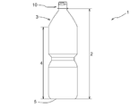
- the bottle container 1 includes a bottomed cylindrical container body 2 and a cylindrical container opening 10 integrally provided at the tip of the container body 2. Equipped with The container port 10 is configured to be able to mount the cap 20.
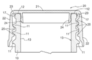
- the cap 20 in the present embodiment includes the top plate portion 21 and a cylindrical portion 22 which is suspended from the peripheral edge of the top plate portion 21 and on which the screw thread 25 is provided on the inner circumferential surface. And an outer ring 23 formed on the inner surface of the top plate 21 and in contact with the outer circumferential surface 17 of the container opening 10 and an inner surface of the top plate 21 and in contact with the inner circumferential surface 13 of the container opening 10 And an inner ring 24 (an example of a seal portion).
- the cap 20 applicable to the present invention is not limited to the one having the above-described configuration, and a conventionally known general cap provided with a seal capable of sealing in contact with the inner peripheral surface of the container opening is used. You may.
- the outer ring 23 and the inner ring 24 have a shape protruding from the inner surface of the top plate 21.
- the length (vertical distance from the top plate portion 21) of the inner ring 24 is longer than the outer ring 23. While the outer ring 23 and the outer peripheral surface 17 of the container opening 10 contact, and the inner ring 24 and the inner peripheral surface 13 of the container opening 10 contact, the bottle container 1 is sealed.
- the material of the cap 20 and the method for producing the same are not particularly limited, and the cap 20 is made of, for example, a resin such as polyethylene, polypropylene, or polystyrene, and the top plate portion 21, the cylindrical portion 22, the outer ring 23, and It can be manufactured by integrally molding the inner ring 24 by a known molding method.
- a resin such as polyethylene, polypropylene, or polystyrene
- the container body 2 is connected to the shoulder 3 connected to the container opening 10, the trunk 4 connected to the shoulder 3, and the trunk 4. And a bottom 5 located at the bottom.
- the bottle container 1 in the present embodiment is a container made of resin such as polyethylene terephthalate (PET), polyethylene, polypropylene or the like.
- PET polyethylene terephthalate
- the bottle container 1 is formed, for example, by injection molding or the like using a preform having a container opening 10, and the container body 2 and the container opening 10 are integrally formed by molding the container body 2 by blow molding. It is what has become.
- Such a bottle container 1 can be used as, for example, a container for beverages such as water and carbonated beverages, and a container for foods such as sources.
- the container opening 10 includes a top surface 12, an inner circumferential surface 13, and an outer circumferential surface 17.
- a thread 11 is provided on the outer peripheral surface 17 of the container port 10.
- the screw thread 11 of the container port 10 and the screw thread 25 of the cap 20 can be screwed together, and the cap 20 is configured to be attachable to and detachable from the container port 10.
- the outer ring 23 contacts the outer peripheral surface 17 of the container opening 10
- the inner ring 24 contacts the inner peripheral surface 13 of the container opening 10. It is done.
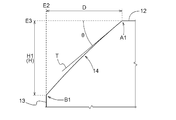
- a circular arc portion 14 which is convex toward the inside of the container is formed between the top surface 12 and the inner peripheral surface 13 of the container opening 10. Furthermore, a second arc 15 that is convex toward the inside of the container is formed between the arc 14 and the top surface 12, and a third arc 16 that is convex toward the inside of the container is an arc. It is formed between 14 and the inner circumferential surface 13. That is, in the container port 10 in the present embodiment, three arcs, that is, the second arc 15, the arc 14, and the third arc 16, are continuously provided from the top surface 12 to the inner circumferential surface 13.
- the second arc portion 15 and the third arc portion 16 correspond to “another arc portion” in the present invention, and the curvature radius of each of the second arc portion 15 and the third arc portion 16 is an arc.
- the radius of curvature of the portion 14 is smaller.
- the tangent line T in the arc portion 14 starts from an intersection point A2 of the virtual extension line E1 of the arc portion 14 and the top surface 12 or the virtual extension line E3 of the top surface 12, and between the top surface 12 and the tangent T
- the angle ⁇ of is preferably 30 ° to 60 °, more preferably 30 ° to 50 °.
- the tangent T in the present embodiment starts from an intersection A2 of the virtual extension E1 of the arc portion 14 and the virtual extension E3 of the top surface 12, and the angle ⁇ is set to 40 °.
- the radius of curvature of the arc portion 14 is 6 mm or less, preferably 1.0 mm to 6.0 mm, and more preferably 1.0 mm to 4.0 mm.
- the radius of curvature of the arc portion 14 in the present embodiment is set to 3.0 mm.
- the radius of curvature of the second arc portion 15 and the third arc portion 16 is preferably 0.1 mm to 1.0 mm.
- the radius of curvature of each of the second arc portion 15 and the third arc portion 16 in the present embodiment is set to 0.3 mm, which is the same.
- the distance D from the intersection point to the virtual extension line E2 of the inner circumferential surface 13 is preferably 0.3 mm to 3.0 mm, more preferably 0.3 mm to 1.0 mm, and most preferably Is 0.3 mm to 0.6 mm.
- the distance D in the present embodiment is 0.33 mm.
- the distance H from the E2 intersection point to the virtual extension line E3 of the top surface 12 is preferably 0.3 mm to 3.0 mm, more preferably 0.3 mm to 1.0 mm, Most preferably, it is 0.3 mm to 0.6 mm.
- the distance H in the present embodiment is 0.32 mm.
- the composition in which the 2nd circular arc part 15 and the 3rd circular arc part 16 are provided is shown, it is not limited to this, The 2nd circular arc part 15 and the 3rd circular arc part 16 It is good also as composition which does not provide.
- the tangent T in the arc portion 14 starts from the connection point A1 between the arc portion 14 and the top surface 12, and the angle ⁇ between the top surface 12 and the tangent T is preferably 30 ° to 60 °, more preferably 30 ° to 50 ° (see FIGS. 4 and 5).
- the distance D from the connection point A1 between the arc portion 14 and the top surface 12 to the virtual extension E2 of the inner circumferential surface 13 is preferably 0.3 mm to 3.0 mm, and the arc portion 14 and the inner circumferential surface It is desirable that the distance H from the connection point B1 with 13 to the virtual extension E3 of the top surface 12 be 0.3 mm to 3.0 mm (see FIGS. 4 and 5).
- the container mouth part of the present invention is applied to the bottle container made of resin
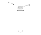
- the present invention may be applied to a bottomed cylindrical preform P or the like in which one end is opened, or may be applied to a container other than resin.
- the shape comparison by the difference in the curvature radius of the circular arc part 14 in the container opening 10 was performed.
- the radius of curvature of the arc portion 14 is 3.0 mm
- the radius of curvature of the arc portion 14 is 6.0 mm.
- no other arc portion than the arc portion 14 is provided, and the angle between the top surface 12 and the tangent line T is 40.degree.
- the distance D from the connection point A1 between the portion 14 and the top surface 12 to the virtual extension E2 of the inner circumferential surface 13 is the same.
- the distance H1 from the connection point B1 with the inner circumferential surface 13 of the arc portion 14 in the embodiment of FIG. 4 to the virtual extension E3 of the top surface 12 is the inner circumferential surface of the arc portion 14 in the embodiment of FIG.
- the distance H2 from the connection point B1 with 13 to the virtual extension E3 of the top surface 12 is longer (H1> H2). That is, even if the angle of the tangent T is the same, it is found that the connection point B1 between the arc portion 14 and the inner circumferential surface 13 is located further downward if the curvature radius of the arc portion 14 is reduced.
- the curvature radius of the arc portion 14 is 3.0 mm
- the curvature radius of each of the second arc portion 15 and the third arc portion 16 is 0.3 mm
- the distance between the top surface 12 and the tangent T is Evaluation which simulated collision of preforms at the time of conveyance by producing 10 preforms (component: PET, weight: 27.5 g) having the container mouth part according to the above-mentioned embodiment whose angle is 40 ° The test was conducted.
- the container port of the present invention can be suitably used in the industrial field relating to a container to which a cap is attached.
Abstract
Description
このような樹脂製容器をコンテナ等に複数収容して搬送する際、樹脂製容器同士の衝突によって、樹脂製容器の口部に打痕傷が生じてしまう場合がある。このような傷のある樹脂製容器の口部にキャップを装着すると、口部の傷によってキャップのシール部に傷がつき、樹脂製容器に充填された内容物がシール部の傷部分から漏れ出す虞がある。
こうした事情を受けて、容器口部に、例えば特許文献1に示されるような、プリフォームの天面と内周面との間に面取り部を形成することによって、プリフォームの口部における打痕傷の発生を低減させて、容器口部の密封性の低下を防止しようとした樹脂製容器が2011年より欧州で製造販売されている。
以下、図面を参照して本発明の容器口部の実施形態について説明する。ここでは、本発明の容器口部を、樹脂製のボトル容器に適用した場合を例として説明する。
上述の実施形態では、第2円弧部15及び第3円弧部16が設けられている構成が示されているが、これに限定されるものではなく、第2円弧部15及び第3円弧部16を設けていない構成としても良い。この場合、円弧部14における接線Tは、円弧部14と天面12との接続点A1を起点とするものとなり、天面12と接線Tとの間の角度θは、好ましくは30°~60°であり、より好ましくは30°~50°である(図4及び図5参照)。また、円弧部14と天面12との接続点A1から内周面13の仮想延長線E2までの距離Dは、0.3mm~3.0mmであることが望ましく、円弧部14と内周面13との接続点B1から天面12の仮想延長線E3までの距離Hは、0.3mm~3.0mmであることが望ましい(図4及び図5参照)。
図4に示される実施例では、円弧部14の曲率半径を3.0mmとし、図5に示される実施例では、円弧部14の曲率半径を6.0mmとした。
2 容器本体
3 肩部
4 胴部
5 底部
10 容器口部
11 ねじ山
12 天面
13 内周面
14 円弧部
15 第2円弧部
16 第3円弧部
17 外周面
20 キャップ
21 天板部
22 筒部
23 アウターリング
24 インナーリング
25 ねじ山
T 接線
E1 円弧部の仮想延長線
E2 内周面の仮想延長線
E3 天面の仮想延長線
A1 円弧部と天面との接続点
A2 円弧部の仮想延長線と天面若しくは天面の仮想延長線との交点
B1 円弧部と内周面との接続点
B2 円弧部の仮想延長線と内周面若しくは内周面の仮想延長線との交点
D 距離
H 距離
P プリフォーム
Claims (7)
- 容器本体に設けられ、内部にシール部を有するキャップを装着したときに、前記シール部が内周面と接触することで密封される容器口部において、
該容器口部の天面と内周面との間に、内側に向かって凸となる円弧部が形成されており、
前記円弧部における接線が、前記円弧部と前記天面との接続点、又は前記円弧部の仮想延長線と前記天面若しくは前記天面の仮想延長線との交点を起点とし、前記天面と前記接線との間の角度が30°~60°であることを特徴とする容器口部。 - 前記円弧部の曲率半径が、6mm以下であることを特徴とする請求項1に記載の容器口部。
- 前記円弧部と前記天面との接続点、又は前記円弧部の仮想延長線と前記天面若しくは前記天面の仮想延長線との交点から、前記内周面の仮想延長線までの距離が、0.3mm~3.0mmであることを特徴とする請求項1又は2に記載の容器口部。
- 前記円弧部と前記内周面との接続点、又は前記円弧部の仮想延長線と前記内周面若しくは前記内周面の仮想延長線との交点から、前記天面の仮想延長線までの距離が、0.3mm~3.0mmであることを特徴とする請求項1~3のいずれか1項に記載の容器口部。
- 前記円弧部と前記天面との間、及び前記円弧部と前記内周面との間に、該円弧部よりも小さい曲率半径を有する別の円弧部が形成されていることを特徴とする請求項1~4のいずれか1項に記載の容器口部。
- 請求項1~5のいずれか1項に記載の容器口部を備える樹脂製容器。
- 請求項1~5のいずれか1項に記載の容器口部を備えるプリフォーム。
Priority Applications (4)
| Application Number | Priority Date | Filing Date | Title |
|---|---|---|---|
| CN201880036826.XA CN110740940A (zh) | 2017-06-23 | 2018-06-06 | 容器口部、具备容器口部的树脂制容器、及具备容器口部的预成形件 |
| US16/618,418 US11518570B2 (en) | 2017-06-23 | 2018-06-06 | Container spout portion, resin made container having the container spout portion and preform having the container spout portion |
| EP18821620.4A EP3643632A4 (en) | 2017-06-23 | 2018-06-06 | CONTAINER MOUTH, RESIN CONTAINER WITH CONTAINER MOUTHING AND PREFORM WITH CONTAINER MOUTHING |
| AU2018288101A AU2018288101B2 (en) | 2017-06-23 | 2018-06-06 | Container spout portion, resin made container having the container spout portion and preform having the container spout portion |
Applications Claiming Priority (2)
| Application Number | Priority Date | Filing Date | Title |
|---|---|---|---|
| JP2017-123442 | 2017-06-23 | ||
| JP2017123442A JP2019006448A (ja) | 2017-06-23 | 2017-06-23 | 容器口部、容器口部を備える樹脂製容器、及び容器口部を備えるプリフォーム |
Publications (1)
| Publication Number | Publication Date |
|---|---|
| WO2018235604A1 true WO2018235604A1 (ja) | 2018-12-27 |
Family
ID=64735922
Family Applications (1)
| Application Number | Title | Priority Date | Filing Date |
|---|---|---|---|
| PCT/JP2018/021755 WO2018235604A1 (ja) | 2017-06-23 | 2018-06-06 | 容器口部、容器口部を備える樹脂製容器、及び容器口部を備えるプリフォーム |
Country Status (6)
| Country | Link |
|---|---|
| US (1) | US11518570B2 (ja) |
| EP (1) | EP3643632A4 (ja) |
| JP (1) | JP2019006448A (ja) |
| CN (1) | CN110740940A (ja) |
| AU (1) | AU2018288101B2 (ja) |
| WO (1) | WO2018235604A1 (ja) |
Citations (5)
| Publication number | Priority date | Publication date | Assignee | Title |
|---|---|---|---|---|
| JPH07257612A (ja) * | 1994-03-25 | 1995-10-09 | Yoshino Kogyosho Co Ltd | 樹脂製容器 |
| JP2005088447A (ja) * | 2003-09-18 | 2005-04-07 | Dainippon Printing Co Ltd | 延伸ブロー成形用中間成形体及び合成樹脂製壜体 |
| JP2015131666A (ja) | 2014-01-14 | 2015-07-23 | 大日本印刷株式会社 | プリフォームおよびプラスチックボトル |
| WO2015181978A1 (ja) * | 2014-05-30 | 2015-12-03 | サントリーホールディングス株式会社 | 容器口部 |
| JP2016159977A (ja) * | 2015-03-05 | 2016-09-05 | 大日本印刷株式会社 | プラスチックボトル、プリフォーム、及び充填体 |
Family Cites Families (5)
| Publication number | Priority date | Publication date | Assignee | Title |
|---|---|---|---|---|
| US4298036A (en) * | 1979-12-13 | 1981-11-03 | Plastic Research Products, Inc. | Dispenser for stick solids |
| FR2839296A1 (fr) * | 2002-07-17 | 2003-11-07 | Tetra Laval Holdings & Finance | Recipient pourvu d'un goulot et equipe d'un bouchon pourvu d'une jupe interne |
| JP4285066B2 (ja) * | 2003-05-02 | 2009-06-24 | 東洋製罐株式会社 | プラスチック容器のキャップ取付構造およびノズルの結晶化方法並びにノズルの内径規制用コアチャック |
| DE20319786U1 (de) * | 2003-12-20 | 2005-05-04 | Alpla-Werke Alwin Lehner Gmbh & Co. Kg | Kunststoffteil (Preform), Kunststoffflasche |
| CN103318495A (zh) * | 2012-09-04 | 2013-09-25 | 西帕机械(杭州)有限公司 | 一种热灌装轻量化饮料瓶瓶口 |
-
2017
- 2017-06-23 JP JP2017123442A patent/JP2019006448A/ja active Pending
-
2018
- 2018-06-06 EP EP18821620.4A patent/EP3643632A4/en active Pending
- 2018-06-06 CN CN201880036826.XA patent/CN110740940A/zh active Pending
- 2018-06-06 WO PCT/JP2018/021755 patent/WO2018235604A1/ja active Application Filing
- 2018-06-06 US US16/618,418 patent/US11518570B2/en active Active
- 2018-06-06 AU AU2018288101A patent/AU2018288101B2/en active Active
Patent Citations (5)
| Publication number | Priority date | Publication date | Assignee | Title |
|---|---|---|---|---|
| JPH07257612A (ja) * | 1994-03-25 | 1995-10-09 | Yoshino Kogyosho Co Ltd | 樹脂製容器 |
| JP2005088447A (ja) * | 2003-09-18 | 2005-04-07 | Dainippon Printing Co Ltd | 延伸ブロー成形用中間成形体及び合成樹脂製壜体 |
| JP2015131666A (ja) | 2014-01-14 | 2015-07-23 | 大日本印刷株式会社 | プリフォームおよびプラスチックボトル |
| WO2015181978A1 (ja) * | 2014-05-30 | 2015-12-03 | サントリーホールディングス株式会社 | 容器口部 |
| JP2016159977A (ja) * | 2015-03-05 | 2016-09-05 | 大日本印刷株式会社 | プラスチックボトル、プリフォーム、及び充填体 |
Non-Patent Citations (1)
| Title |
|---|
| See also references of EP3643632A4 |
Also Published As
| Publication number | Publication date |
|---|---|
| US20200317387A1 (en) | 2020-10-08 |
| CN110740940A (zh) | 2020-01-31 |
| US11518570B2 (en) | 2022-12-06 |
| EP3643632A4 (en) | 2021-04-21 |
| AU2018288101A1 (en) | 2020-01-02 |
| JP2019006448A (ja) | 2019-01-17 |
| EP3643632A1 (en) | 2020-04-29 |
| AU2018288101B2 (en) | 2023-12-07 |
| AU2018288101A2 (en) | 2020-01-16 |
Similar Documents
| Publication | Publication Date | Title |
|---|---|---|
| US4143785A (en) | Plastic vacuum sealing cap | |
| US11807413B2 (en) | Container finish portion with polished buffer zone | |
| US20080128380A1 (en) | Plastic container and closure and system and method of making the same | |
| CA3079406C (en) | Closure and package that vents at high pressure | |
| JP2015131666A (ja) | プリフォームおよびプラスチックボトル | |
| JP6059935B2 (ja) | 包装容器 | |
| JP2009154943A (ja) | 合成樹脂製ボトル | |
| US20230192344A1 (en) | Container preform with tamper evidence finish portion | |
| WO2018235604A1 (ja) | 容器口部、容器口部を備える樹脂製容器、及び容器口部を備えるプリフォーム | |
| JP2007030927A (ja) | キャップ及びキャップ付ボトル缶 | |
| KR20210130135A (ko) | 플라스틱 캡 | |
| JP2000062743A (ja) | 丸型プラスチックボトル | |
| JP2014234162A (ja) | 合成樹脂製ボトル | |
| JP6207896B2 (ja) | プラスチックキャップ及びキャップ付ポリエステルボトル | |
| JP7417870B2 (ja) | プラスチックボトルおよびプリフォーム | |
| JP6831618B2 (ja) | プラスチックボトル、プリフォーム、及び充填体 | |
| JP4531365B2 (ja) | 延伸ブロー成形用中間成形体及び合成樹脂製壜体 | |
| US10874234B2 (en) | Beverage container | |
| JP4017838B2 (ja) | 容器の口部 | |
| CA2412366A1 (en) | Plastic closure cap, with sealing skirt | |
| WO2015181978A1 (ja) | 容器口部 | |
| JP2017081567A (ja) | プラスチック容器 | |
| JP2018070168A (ja) | 合成樹脂製容器 | |
| JP2002205719A (ja) | 容 器 | |
| CN203921424U (zh) | 一种化学容器 |
Legal Events
| Date | Code | Title | Description |
|---|---|---|---|
| 121 | Ep: the epo has been informed by wipo that ep was designated in this application |
Ref document number: 18821620 Country of ref document: EP Kind code of ref document: A1 |
|
| NENP | Non-entry into the national phase |
Ref country code: DE |
|
| ENP | Entry into the national phase |
Ref document number: 2018288101 Country of ref document: AU Date of ref document: 20180606 Kind code of ref document: A |
|
| WWE | Wipo information: entry into national phase |
Ref document number: 2018821620 Country of ref document: EP |
|
| ENP | Entry into the national phase |
Ref document number: 2018821620 Country of ref document: EP Effective date: 20200123 |