WO2018230618A1 - スロット型光ケーブル - Google Patents
スロット型光ケーブル Download PDFInfo
- Publication number
- WO2018230618A1 WO2018230618A1 PCT/JP2018/022638 JP2018022638W WO2018230618A1 WO 2018230618 A1 WO2018230618 A1 WO 2018230618A1 JP 2018022638 W JP2018022638 W JP 2018022638W WO 2018230618 A1 WO2018230618 A1 WO 2018230618A1
- Authority
- WO
- WIPO (PCT)
- Prior art keywords
- slot
- cable
- type optical
- optical fiber
- optical cable
- Prior art date
Links
Images


Classifications
-
- G—PHYSICS
- G02—OPTICS
- G02B—OPTICAL ELEMENTS, SYSTEMS OR APPARATUS
- G02B6/00—Light guides; Structural details of arrangements comprising light guides and other optical elements, e.g. couplings
- G02B6/44—Mechanical structures for providing tensile strength and external protection for fibres, e.g. optical transmission cables
- G02B6/4401—Optical cables
- G02B6/4407—Optical cables with internal fluted support member
- G02B6/4408—Groove structures in support members to decrease or harmonise transmission losses in ribbon cables
-
- G—PHYSICS
- G02—OPTICS
- G02B—OPTICAL ELEMENTS, SYSTEMS OR APPARATUS
- G02B6/00—Light guides; Structural details of arrangements comprising light guides and other optical elements, e.g. couplings
- G02B6/44—Mechanical structures for providing tensile strength and external protection for fibres, e.g. optical transmission cables
- G02B6/4401—Optical cables
- G02B6/4403—Optical cables with ribbon structure
- G02B6/4404—Multi-podded
Definitions
- the present invention relates to a slot type optical cable.
- Patent Document 1 discloses a structure in which a protruding shape is provided on the surface of a cable jacket (also referred to as a sheath).
- a slot-type optical cable of the present disclosure includes an optical fiber core, a slot rod having a plurality of ribs that form a groove capable of accommodating the optical fiber core, and a cable jacket provided around the slot rod.
- the cable jacket includes a sheath portion formed by connecting the outermost peripheral edges of adjacent ribs in a straight line and having the same thickness around the slot rod.
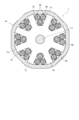
- FIG. 1 is a diagram showing an example of a slotted optical cable according to the first embodiment of the present invention.
- FIG. 2A is a diagram showing an example of the structure of the intermittent tape core wire, and shows a state where the intermittent tape core wire is opened in the arrangement direction.
- FIG. 2B is a cross-sectional view taken along line BB in FIG. 2A.
- FIG. 3 is a diagram illustrating an example of a slot-type optical cable according to the second embodiment of the present invention.
- an object of the present invention is to provide a slot-type optical cable that can be mounted at high density while avoiding an increase in the diameter of the cable and has low friction when laying in the duct.
- a slot-type optical cable includes: (1) an optical fiber core wire, a slot rod having a plurality of ribs that form grooves capable of accommodating the optical fiber core wire, and a periphery of the slot rod.
- a slot-type optical cable having a cable jacket provided, wherein the cable jacket is formed with substantially the same thickness around the slot rod by connecting the outermost peripheral edges of adjacent ribs in a straight line. It has a sheath part.
- the periphery of the slot rod is covered with a sheath with a polygonal outermost shape, and the contact area with the inner wall of the duct is reduced compared to the case where a circular cable is wired in the duct. It becomes easy. There is no need to provide a projection on the cable jacket as in the prior art, and if the cable diameter is kept the same as the conventional one, the diameter of the slot rod can be increased. Density mounting becomes possible.
- the number of the ribs is 6 or more and 8 or less.
- bending directionality appears, so that bending becomes difficult.
- it becomes difficult to bend when the number of grooves is odd, such as 5 grooves.
- the number of ribs exceeds eight, the cable becomes a substantially circular cable and the contact range with the inner wall of the duct increases, so friction increases and wiring into the duct becomes difficult.
- the number of ribs is 6 to 8 and the groove is formed, it is possible to provide a cable that has no bending direction and is easy to be laid in a pipe line.
- the density of the material used for the sheath portion is less than 0.942 g / cm 3 .
- the sheath portion is formed of a relatively low density material, the sheath portion can be easily pushed out around the slot rod, so that the productivity of the cable is improved.
- a tape core wire in which the optical fiber core wires are arranged is housed, and the tape core wire is not connected to the connecting portion in the longitudinal direction between some or all of the adjacent optical fiber core wires. It is the intermittent tape core wire in which the connection part was formed intermittently. Since the intermittent tape core has flexibility, the use rate of the intermittent tape core can be increased as compared with a general tape core.
- FIG. 1 is a diagram showing an example of a slot-type optical cable according to the first embodiment of the present invention
- FIGS. 2A and 2B are diagrams showing an example of the structure of an intermittent tape core.
- the slot-type optical cable 1 shown in FIG. 1 includes, for example, a slot rod 10, an optical unit 30, a press winding tape 40 that is wound vertically or horizontally around the slot rod 10, and a press winding tape 40. And an applied cable jacket 41.
- the slot rod 10 has a tension member 11 embedded in the center thereof.
- a wire having a resistance to tension and compression for example, a steel wire or FRP (Fiber Reinforced Plastics) is used.
- a plurality of (for example, six) slot grooves 12 having a spiral shape or SZ shape are formed on the outer peripheral surface of the slot rod 10 along the longitudinal direction of the cable.
- the slot groove 12 corresponds to the groove of the present invention.
- the slot rod 10 has, for example, six slot ribs 13 extending radially from the periphery of the tension member 11, and the slot rib 13 forms a slot groove 12 and is separated from the other slot grooves 12. Yes.
- the slot rib 13 corresponds to the rib of the present invention.
- a tracer mark for identifying the position of the slot groove 12 can be provided on the outer peripheral surface of the slot rib 13.
- the slot groove 12 accommodates, for example, one using a plurality of 12-core intermittent tape core wires 20.
- Intermittent tape cores are formed by arranging a plurality of optical fiber cores in parallel and intermittently connecting some or all adjacent optical fiber cores by a connecting part and a non-connecting part. It is. 2A shows a state where the intermittent tape cores are opened in the arrangement direction, FIG. 2B shows a cross-sectional view taken along the line BB of FIG. 2A, and the intermittent tape core 20 shown in FIG. The line is configured to be intermittently connected every two cores.
- a tape coating 24 made of an ultraviolet curable resin or the like is provided around each optical fiber core wire 21.
- the core wires obtained by integrating two cores are connected by a connecting portion 22 and a non-connecting portion 23. Intermittently connected.
- the tape coating 24 is connected, and in the non-connecting portion 23, the adjacent tape coating 24 is separated without being connected.
- an intermittent tape core wire does not need to provide a connection part and a non-connection part for every 2 cores, For example, you may connect intermittently by a connection part and a non-connection part for every 1 core.
- the optical fiber core 21 accommodated in the intermittent tape core is, for example, on the outside of what is called an optical fiber strand in which a glass fiber having a standard outer diameter of 125 ⁇ m is coated with a coating outer diameter of about 250 ⁇ m.
- an optical fiber strand in which a glass fiber having a standard outer diameter of 125 ⁇ m is coated with a coating outer diameter of about 250 ⁇ m.
- the present invention is not limited to this, and a thin fiber having a coating outer diameter in the range of 135 ⁇ m to 220 ⁇ m, for example, about 165 ⁇ m or 200 ⁇ m may be used. If a thin fiber is used, high-density mounting becomes even easier.
- the optical unit 30 shown in FIG. 1 is formed by, for example, collecting a plurality of 12-core intermittent tape core wires 20 and twisting them in a spiral shape.
- the plurality of twisted tape core wires 20 may be bundled with a bundle material 31 for identification.
- the twist of the intermittent tape core wire 20 may be an SZ shape that is periodically reversed in addition to a spiral shape in one direction.
- the intermittent tape core wire 20 is more flexible than a general tape core wire, and if the optical unit 30 is composed of an intermittent tape core wire, the occupation ratio of the optical fiber core wire 21 can be increased. .
- a tape core wire which comprises the optical unit 30 such an intermittent tape core wire does not need to be used but a connection type
- the slot rod 10 is wound with a press-wrapping tape 40 so that the optical unit 30 does not jump out, and the outermost peripheral shape is gathered into a polygon (for example, a dodecagon).
- the press-wound tape 40 is wound so that the outermost peripheral edge of the adjacent slot rib 13 (the edge of the slot rib 13 positioned on the outermost side in the radial direction) is linearly tied.
- the presser tape 40 for example, a non-woven fabric formed into a tape shape, a laminate of a base material such as polyethylene terephthalate (PET) and the non-woven fabric, or the like is used.
- a water absorbing agent for example, water absorption powder
- the holding tape functions as a water absorbing layer, it is possible to stop water on the intermittent tape core.
- a cable jacket 41 formed by extruding a resin such as PE (polyethylene) or PVC (polyvinyl chloride) is provided on the outside of the press-wrapping tape 40.
- the cable jacket 41 has a sheath portion 42 whose outermost peripheral shape is formed in a polygon (for example, a dodecagon).
- the cable jacket 41 may be provided with a jacket tear string (not shown) vertically.
- the cable jacket 41 has a jacket tear string in addition to the sheath portion 42.
- a dodecagon is used as an extrusion mold.
- the outermost peripheral edges of the slot ribs 13 are, for example, A, B, and C shown in FIG. 1, and A and B are linearly connected, and B and C are linearly connected.
- the sheath portion 42 is formed with substantially the same thickness around the slot rod 10, specifically, the outside of the slot groove 12 and the outside of the slot rib 13.
- the periphery of the slot rod 10 is covered with the sheath portion 42 whose outermost peripheral shape is a polygon, and the contact range with the inner wall of the duct is reduced compared to the case where a circular cable is wired in the duct. Wiring into the duct is easy. Further, unlike the prior art, there is no need to provide a protrusion on the cable jacket, and if the cable diameter is kept the same as the conventional one, the diameter of the slot rod 10 can be increased. High-density mounting of wires becomes possible.
- Density of the material used in the sheath portion 42 is preferably less than 0.942 g / cm 3 (e.g., 0.93g / cm 3).
- a material having a density of 0.942 g / cm 3 or more is also referred to as high density polyethylene, and a material having a density of less than 0.942 g / cm 3 is also referred to as medium density or low density polyethylene.
- the sheath part 42 is formed of a relatively low density material, the sheath part can be easily pushed out around the slot rod, so that the productivity of the cable is improved.
- FIG. 3 is a diagram illustrating an example of a slot-type optical cable according to the second embodiment of the present invention.
- the slot rod according to the first embodiment is formed by the six slot ribs 13, it may be formed by eight slot ribs 13 as shown in FIG.
- the slot ribs 13 are preferably 6 or more and 8 or less. The reason is that when the number of the slot ribs is less than 6, the bending directionality appears, so that the bending becomes difficult. In particular, when the number of slot grooves is an odd number, for example, five grooves, it becomes difficult to bend. On the other hand, when the number of slot ribs exceeds 8, the cable becomes a substantially circular cable and the contact range with the inner wall of the duct increases, so that friction during installation increases and wiring into the duct becomes difficult.
- SYMBOLS 1 Slot type optical cable, 10 ... Slot rod, 11 ... Tension member, 12 ... Slot groove, 13 ... Slot rib, 20 ... Intermittent tape core wire, 21 ... Optical fiber core wire, 22 ... Connection part, 23 ... Non-connection part 24 ... Tape covering, 30 ... Optical unit, 31 ... Bundle material, 40 ... Press-wrapping tape, 41 ... Cable jacket, 42 ... Sheath part.
Abstract
光ファイバ心線と、光ファイバ心線を収納可能な溝を形成する複数のリブを有したスロットロッドと、スロットロッドの周囲に設けられたケーブル外被とを備えたスロット型光ケーブルである。ケーブル外被は、隣り合うリブの最外周縁を直線状に結んで、スロットロッドの周囲に略同じ厚みで形成されたシース部を有する。
Description
本発明は、スロット型光ケーブルに関する。
特許文献1には、ケーブル外被(シースともいう)の表面に突状形状を設けた構造が開示されている。
本開示のスロット型光ケーブルは、光ファイバ心線と、該光ファイバ心線を収納可能な溝を形成する複数のリブを有したスロットロッドと、該スロットロッドの周囲に設けられたケーブル外被とを備えたスロット型光ケーブルであって、前記ケーブル外被は、隣り合うリブの最外周縁を直線状に結んで、前記スロットロッドの周囲に略同じ厚みで形成されたシース部を有する。
[本開示が解決しようとする課題]
特許文献1のような構造とした場合、突状形状の分だけケーブル径が大きくなる、といった問題が生じる。このため、スロット型光ケーブルにおいて、ケーブルの大径化を避けつつ、布設時の摩擦を低減させる構造が望まれる。
特許文献1のような構造とした場合、突状形状の分だけケーブル径が大きくなる、といった問題が生じる。このため、スロット型光ケーブルにおいて、ケーブルの大径化を避けつつ、布設時の摩擦を低減させる構造が望まれる。
そこで、ケーブルの大径化を避けつつ、高密度実装が可能で、ダクト内布設時の摩擦が小さいスロット型光ケーブルを提供することを目的とする。
[本開示の効果]
本開示によれば、ケーブルの大径化を回避でき、また、光ファイバ心線の高密度実装が可能で、ダクト内布設時の摩擦を小さくすることができる。
本開示によれば、ケーブルの大径化を回避でき、また、光ファイバ心線の高密度実装が可能で、ダクト内布設時の摩擦を小さくすることができる。
[本発明の実施形態の説明]
最初に本発明の実施形態の内容を列記して説明する。
本発明の一態様に係るスロット型光ケーブルは、(1)光ファイバ心線と、該光ファイバ心線を収納可能な溝を形成する複数のリブを有したスロットロッドと、該スロットロッドの周囲に設けられたケーブル外被とを備えたスロット型光ケーブルであって、前記ケーブル外被は、隣り合うリブの最外周縁を直線状に結んで、前記スロットロッドの周囲に略同じ厚みで形成されたシース部を有する。スロットロッドの周囲は、最外周形状が多角形のシース部で覆われており、円形のケーブルをダクト内に配線した場合に比べてダクト内壁との接触範囲が減るため、ダクト内への配線が容易になる。先行技術のように、ケーブル外被に突起を設ける必要も無く、また、仮にケーブル径を従来と同じ大きさに維持した場合には、スロットロッドの径を大きくできることから、光ファイバ心線の高密度実装が可能になる。
(2)前記リブの数が6本以上8本以下である。リブの数が6本未満の場合、曲げの方向性が出てくるため、曲げにくくなる。特に、例えば5溝のように溝が奇数になると、曲げにくくなる。一方、リブの数が8本を超えると、ほぼ円形のケーブルになってダクト内壁との接触範囲が増えるので、摩擦が増え、ダクト内への配線が難しくなる。これに対し、リブの数が6~8本で溝を形成すれば、曲げの方向性が無く、管路に布設しやすいケーブルを提供することができる。
(3)前記シース部に用いられる材料の密度が0.942g/cm3未満である。シース部を比較的低密度の材料で形成すれば、シース部をスロットロッドの周囲に押し出しやすくなるため、ケーブルの生産性が向上する。
(4)前記溝には、前記光ファイバ心線を並べたテープ心線が収納され、該テープ心線は、一部、または全ての隣り合う光ファイバ心線間の長手方向に連結部と非連結部が間欠的に形成された間欠テープ心線である。間欠テープ心線は柔軟性を有するため、間欠テープ心線を用いれば、一般的なテープ心線に比べて占有率を上げることができる。
(3)前記シース部に用いられる材料の密度が0.942g/cm3未満である。シース部を比較的低密度の材料で形成すれば、シース部をスロットロッドの周囲に押し出しやすくなるため、ケーブルの生産性が向上する。
(4)前記溝には、前記光ファイバ心線を並べたテープ心線が収納され、該テープ心線は、一部、または全ての隣り合う光ファイバ心線間の長手方向に連結部と非連結部が間欠的に形成された間欠テープ心線である。間欠テープ心線は柔軟性を有するため、間欠テープ心線を用いれば、一般的なテープ心線に比べて占有率を上げることができる。
[本発明の実施形態の詳細]
以下、添付図面を参照しながら、本発明によるスロット型光ケーブルの好適な実施の形態について説明する。
図1は、本発明の第1実施形態によるスロット型光ケーブルの一例を示す図であり、図2A,2Bは、間欠テープ心線の構造の一例を示す図である。
以下、添付図面を参照しながら、本発明によるスロット型光ケーブルの好適な実施の形態について説明する。
図1は、本発明の第1実施形態によるスロット型光ケーブルの一例を示す図であり、図2A,2Bは、間欠テープ心線の構造の一例を示す図である。
図1に示したスロット型光ケーブル1は、例えばスロットロッド10と、光ユニット30と、スロットロッド10の周囲に縦添えまたは横巻きで巻かれた押さえ巻きテープ40と、押さえ巻きテープ40の周囲に施されたケーブル外被41とを備えている。
スロットロッド10は、その中心部にテンションメンバ11が埋設されている。テンションメンバ11は、引張り及び圧縮に対する耐力を有する線材、例えば、鋼線やFRP(Fiber Reinforced Plastics)などが用いられる。
スロットロッド10は、その中心部にテンションメンバ11が埋設されている。テンションメンバ11は、引張り及び圧縮に対する耐力を有する線材、例えば、鋼線やFRP(Fiber Reinforced Plastics)などが用いられる。
また、スロットロッド10の外周面には、ケーブル長手方向に沿って螺旋状またはSZ状のスロット溝12が複数条(例えば6つ)形成されている。なお、スロット溝12が本発明の溝に相当する。
詳しくは、スロットロッド10は、テンションメンバ11の周囲から放射状に延びた例えば6つのスロットリブ13を有しており、スロットリブ13がスロット溝12を形成し、他のスロット溝12と区分している。なお、スロットリブ13が本発明のリブに相当する。なお、スロットリブ13の外周面には、スロット溝12の位置を識別するトレーサマークを設けることも可能である。
詳しくは、スロットロッド10は、テンションメンバ11の周囲から放射状に延びた例えば6つのスロットリブ13を有しており、スロットリブ13がスロット溝12を形成し、他のスロット溝12と区分している。なお、スロットリブ13が本発明のリブに相当する。なお、スロットリブ13の外周面には、スロット溝12の位置を識別するトレーサマークを設けることも可能である。
スロット溝12には、例えば12心の間欠テープ心線20を複数枚使用したものが収容されている。
間欠テープ心線とは、複数本の光ファイバ心線が平行一列に配列され、一部、または全ての隣り合う光ファイバ心線同士を連結部と非連結部により間欠的に連結してなるものである。図2Aは間欠テープ心線を配列方向に開いた状態を、図2Bは図2AのB-B線矢視断面図をそれぞれ示しており、図示の間欠テープ心線20は、12心のテープ心線が2心毎に間欠的に接続されて構成されている。
間欠テープ心線とは、複数本の光ファイバ心線が平行一列に配列され、一部、または全ての隣り合う光ファイバ心線同士を連結部と非連結部により間欠的に連結してなるものである。図2Aは間欠テープ心線を配列方向に開いた状態を、図2Bは図2AのB-B線矢視断面図をそれぞれ示しており、図示の間欠テープ心線20は、12心のテープ心線が2心毎に間欠的に接続されて構成されている。
図2Bに示すように、各光ファイバ心線21の周囲には、紫外線硬化樹脂等によるテープ被覆24が設けられ、例えば2心を一体化した心線同士が連結部22と非連結部23により間欠的に連結されている。連結部22では、テープ被覆24が連結されており、非連結部23では、隣り合うテープ被覆24が連結されずに分離している。なお、間欠テープ心線は、2心毎に連結部と非連結部を設けなくてもよく、例えば1心毎に連結部と非連結部で間欠的に連結してもよい。
この間欠テープ心線に収容される光ファイバ心線21は、例えば、標準外径125μmのガラスファイバに被覆外径が250μm前後の被覆を施した光ファイバ素線と称されるものの外側に、さらに着色被覆を施したものであるが、これに限られるものでは無く、被覆外径が135μmから220μmの範囲、例えば、165μmや200μm程度の細径ファイバであってもよい。細径ファイバを用いれば、高密度実装がより一層容易になる。
図1に示す光ユニット30は、例えば12心の間欠テープ心線20を複数枚集め、螺旋状に撚って形成されている。なお、撚られた複数枚のテープ心線20は、識別用のバンドル材31で束ねられていてもよい。また、間欠テープ心線20の撚りは、一方向の螺旋状の他、周期的に反転するSZ状であってもよい。
間欠テープ心線20は、一般的なテープ心線に比べて柔軟性を有しており、光ユニット30を間欠テープ心線で構成すれば、光ファイバ心線21の占有率を上げることができる。なお、光ユニット30を構成するテープ心線としては、このような間欠テープ心線を用いなくともよく、連結型のテープ心線を用いたり、単心の光ファイバ心線を複数揃えたりしたものであってもよい。
間欠テープ心線20は、一般的なテープ心線に比べて柔軟性を有しており、光ユニット30を間欠テープ心線で構成すれば、光ファイバ心線21の占有率を上げることができる。なお、光ユニット30を構成するテープ心線としては、このような間欠テープ心線を用いなくともよく、連結型のテープ心線を用いたり、単心の光ファイバ心線を複数揃えたりしたものであってもよい。
スロットロッド10は、光ユニット30が飛び出さないように押さえ巻きテープ40で巻かれ、最外周形状が多角形(例えば十二角形)にまとめられている。詳しくは、押さえ巻きテープ40を、隣り合うスロットリブ13の最外周縁(スロットリブ13の、径方向で最も外周側に位置する縁)を直線状に結ぶように巻いている。
押さえ巻きテープ40は、例えば、不織布をテープ状に形成したものや、ポリエチレンテレフタレート(PET)等の基材と不織布とを貼り合わせたもの等が用いられる。なお、押さえ巻きテープに吸水剤(例えば吸水パウダー)を付与してもよい。押さえ巻きテープを吸水層として機能させれば、間欠テープ心線などへの止水が可能になる。
押さえ巻きテープ40の外側には、例えばPE(ポリエチレン)、PVC(ポリ塩化ビニル)等の樹脂を押し出し成型したケーブル外被41が設けられている。
押さえ巻きテープ40の外側には、例えばPE(ポリエチレン)、PVC(ポリ塩化ビニル)等の樹脂を押し出し成型したケーブル外被41が設けられている。
ケーブル外被41は、最外周形状が多角形(例えば十二角形)に形成されたシース部42を有している。なお、ケーブル外被41中に、外被引き裂き紐(図示省略)を縦添えして設けてもよく、その場合、ケーブル外被41は、シース部42のほか、外被引き裂き紐も有する。
押し出し成型用の型として、例えば十二角形のものを用い、押さえ巻きテープ40で巻かれたリブ本数が6本のスロットロッド10をこの型内に配置し、所定の樹脂を供給すると、図1に示すように、シース部42は、隣り合うスロットリブ13の最外周縁(スロットリブ13の、径方向で最も外周側に位置する縁)を直線状に結んで覆われることになる。具体的には、スロットリブ13の最外周縁は、図1に示す例えばA,B,Cであり、AとBが直線状に結ばれ、BとCが直線状に結ばれている。また、シース部42は、スロットロッド10の周囲、詳しくは、スロット溝12の外側やスロットリブ13の外側を、略同じ厚みで形成される。
押し出し成型用の型として、例えば十二角形のものを用い、押さえ巻きテープ40で巻かれたリブ本数が6本のスロットロッド10をこの型内に配置し、所定の樹脂を供給すると、図1に示すように、シース部42は、隣り合うスロットリブ13の最外周縁(スロットリブ13の、径方向で最も外周側に位置する縁)を直線状に結んで覆われることになる。具体的には、スロットリブ13の最外周縁は、図1に示す例えばA,B,Cであり、AとBが直線状に結ばれ、BとCが直線状に結ばれている。また、シース部42は、スロットロッド10の周囲、詳しくは、スロット溝12の外側やスロットリブ13の外側を、略同じ厚みで形成される。
このように、スロットロッド10の周囲は、最外周形状が多角形のシース部42で覆われており、円形のケーブルをダクト内に配線した場合に比べてダクト内壁との接触範囲が減るため、ダクト内への配線が容易になる。そして、先行技術のように、ケーブル外被に突起を設ける必要も無く、また、仮にケーブル径を従来と同じ大きさに維持した場合には、スロットロッド10の径を大きくできることから、光ファイバ心線の高密度実装が可能になる。
シース部42に用いられる材料の密度は、0.942g/cm3未満(例えば0.93g/cm3)であることが好ましい。なお、0.942g/cm3以上の密度のものを高密度ポリエチレンともいい、0.942g/cm3未満の密度のものを中密度や低密度ポリエチレンともいう。このように、シース部42を比較的低密度の材料で形成すれば、シース部をスロットロッドの周囲に押し出しやすくなるため、ケーブルの生産性が向上する。
図3は、本発明の第2実施形態によるスロット型光ケーブルの一例を示す図である。
上記第1実施形態によるスロットロッドは6本のスロットリブ13で形成したが、図3に示すように、8本のスロットリブ13で形成してもよい。
なお、スロットリブ13は6本以上8本以下であることが好ましい。その理由は、スロットリブの数が6本未満の場合、曲げの方向性が出てくるため、曲げにくくなる。特に、例えば5溝のようにスロット溝の数が奇数になると、曲げにくくなる。一方、スロットリブの数が8本を超えると、ほぼ円形のケーブルになってダクト内壁との接触範囲が増えるので、布設時の摩擦が大きくなり、ダクト内への配線が難しくなる。
上記第1実施形態によるスロットロッドは6本のスロットリブ13で形成したが、図3に示すように、8本のスロットリブ13で形成してもよい。
なお、スロットリブ13は6本以上8本以下であることが好ましい。その理由は、スロットリブの数が6本未満の場合、曲げの方向性が出てくるため、曲げにくくなる。特に、例えば5溝のようにスロット溝の数が奇数になると、曲げにくくなる。一方、スロットリブの数が8本を超えると、ほぼ円形のケーブルになってダクト内壁との接触範囲が増えるので、布設時の摩擦が大きくなり、ダクト内への配線が難しくなる。
今回開示された実施の形態はすべての点で例示であって制限的なものではないと考えられるべきである。本発明の範囲は、上記した意味ではなく、請求の範囲によって示され、請求の範囲と均等の意味および範囲内でのすべての変更が含まれることが意図される。
1…スロット型光ケーブル、10…スロットロッド、11…テンションメンバ、12…スロット溝、13…スロットリブ、20…間欠テープ心線、21…光ファイバ心線、22…連結部、23…非連結部、24…テープ被覆、30…光ユニット、31…バンドル材、40…押さえ巻きテープ、41…ケーブル外被、42…シース部。
Claims (4)
- 光ファイバ心線と、該光ファイバ心線を収納可能な溝を形成する複数のリブを有したスロットロッドと、該スロットロッドの周囲に設けられたケーブル外被とを備えたスロット型光ケーブルであって、
前記ケーブル外被は、隣り合うリブの最外周縁を直線状に結んで、前記スロットロッドの周囲に略同じ厚みで形成されたシース部を有する、スロット型光ケーブル。 - 前記リブの数が6本以上8本以下である、請求項1に記載のスロット型光ケーブル。
- 前記シース部に用いられる材料の密度が0.942g/cm3未満である、請求項1または2に記載のスロット型光ケーブル。
- 前記溝には、前記光ファイバ心線を並べたテープ心線が収納され、該テープ心線は、一部、または全ての隣り合う光ファイバ心線間の長手方向に連結部と非連結部が間欠的に形成された間欠テープ心線である、請求項1から3のいずれか一項に記載のスロット型光ケーブル。
Priority Applications (4)
| Application Number | Priority Date | Filing Date | Title |
|---|---|---|---|
| US16/622,536 US11194108B2 (en) | 2017-06-14 | 2018-06-13 | Slot-type optical cable |
| JP2019525495A JPWO2018230618A1 (ja) | 2017-06-14 | 2018-06-13 | スロット型光ケーブル |
| EP18817845.3A EP3640694A4 (en) | 2017-06-14 | 2018-06-13 | SLOTTED OPTICAL CABLE |
| CN201880039545.XA CN110770621A (zh) | 2017-06-14 | 2018-06-13 | 槽型光缆 |
Applications Claiming Priority (2)
| Application Number | Priority Date | Filing Date | Title |
|---|---|---|---|
| JP2017116639 | 2017-06-14 | ||
| JP2017-116639 | 2017-06-14 |
Publications (1)
| Publication Number | Publication Date |
|---|---|
| WO2018230618A1 true WO2018230618A1 (ja) | 2018-12-20 |
Family
ID=64660197
Family Applications (1)
| Application Number | Title | Priority Date | Filing Date |
|---|---|---|---|
| PCT/JP2018/022638 WO2018230618A1 (ja) | 2017-06-14 | 2018-06-13 | スロット型光ケーブル |
Country Status (5)
| Country | Link |
|---|---|
| US (1) | US11194108B2 (ja) |
| EP (1) | EP3640694A4 (ja) |
| JP (1) | JPWO2018230618A1 (ja) |
| CN (1) | CN110770621A (ja) |
| WO (1) | WO2018230618A1 (ja) |
Cited By (2)
| Publication number | Priority date | Publication date | Assignee | Title |
|---|---|---|---|---|
| WO2020246511A1 (ja) * | 2019-06-07 | 2020-12-10 | 住友電気工業株式会社 | 光ファイバケーブルおよび光ファイバケーブルの製造方法 |
| CN114675386A (zh) * | 2022-04-01 | 2022-06-28 | 杭州富通通信技术股份有限公司 | 一种光缆 |
Families Citing this family (1)
| Publication number | Priority date | Publication date | Assignee | Title |
|---|---|---|---|---|
| CN110770621A (zh) * | 2017-06-14 | 2020-02-07 | 住友电气工业株式会社 | 槽型光缆 |
Citations (9)
| Publication number | Priority date | Publication date | Assignee | Title |
|---|---|---|---|---|
| DE2511019A1 (de) * | 1975-03-11 | 1976-09-23 | Siemens Ag | Grundelement zum aufbau optischer kabel |
| JPH0271808U (ja) | 1988-11-19 | 1990-05-31 | ||
| JPH06102443A (ja) * | 1992-03-31 | 1994-04-15 | American Teleph & Telegr Co <Att> | 光ファイバケーブルおよび光ファイバケーブルコア |
| JP2006018000A (ja) * | 2004-07-01 | 2006-01-19 | Fujikura Ltd | Szスロット型ケーブル及び前記szスロット型ケーブルに使用するszスロット |
| JP2008286940A (ja) * | 2007-05-16 | 2008-11-27 | Furukawa Electric Co Ltd:The | 難燃性光ケーブル |
| WO2011043324A1 (ja) * | 2009-10-06 | 2011-04-14 | 株式会社フジクラ | 光ファイバケーブル |
| JP2013142764A (ja) * | 2012-01-11 | 2013-07-22 | Sumitomo Electric Ind Ltd | 光ファイバケーブル |
| JP2015129887A (ja) * | 2014-01-08 | 2015-07-16 | 住友電気工業株式会社 | 空気圧送用光ファイバケーブル |
| JP2016018088A (ja) * | 2014-07-09 | 2016-02-01 | 住友電気工業株式会社 | 光ケーブルの製造方法 |
Family Cites Families (50)
| Publication number | Priority date | Publication date | Assignee | Title |
|---|---|---|---|---|
| GB1409303A (en) * | 1972-09-20 | 1975-10-08 | Post Office | Optical strands |
| JPH01163710A (ja) * | 1987-02-25 | 1989-06-28 | Sumitomo Electric Ind Ltd | 光ケ−ブル |
| DE58907028D1 (de) * | 1988-08-30 | 1994-03-31 | Siemens Ag | Optisches Kabel mit einem Trägerkörper. |
| GB8908446D0 (en) * | 1989-04-14 | 1989-06-01 | Bicc Plc | Optical cable |
| US5166998A (en) * | 1992-02-21 | 1992-11-24 | Siecor Corporation | Optical ribbon cable component |
| TW289803B (ja) * | 1994-07-06 | 1996-11-01 | Furukawa Electric Co Ltd | |
| US5661836A (en) * | 1995-02-20 | 1997-08-26 | Sumitomo Electric Industries, Ltd. | Optical cable and manufacturing method thereof |
| US5561730A (en) * | 1995-02-23 | 1996-10-01 | Siecor Corporation | Cable containing fiber ribbons with optimized frictional properties |
| JPH08234064A (ja) * | 1995-02-27 | 1996-09-13 | Sumitomo Electric Ind Ltd | 光ファイバケーブル |
| CA2196454C (en) * | 1995-06-08 | 2005-12-27 | Eiji Konda | Optical fiber cable |
| KR970019133U (ko) * | 1995-10-31 | 1997-05-26 | 광케이블의 볼록형 슬롯 코어 형상 | |
| US5668912A (en) * | 1996-02-07 | 1997-09-16 | Alcatel Na Cable Systems, Inc. | Rectangular optical fiber cable |
| US5848212A (en) * | 1996-09-10 | 1998-12-08 | Siecor Corporation | High density optical cable |
| US6160940A (en) * | 1997-06-05 | 2000-12-12 | Corning Cable Systems Llc | Fiber optic cable for installation in a cable passageway and methods and an apparatus for producing the same |
| TW498174B (en) * | 1997-07-15 | 2002-08-11 | Sumitomo Electric Industries | Optical cable and spacer for optical cable |
| US6052502A (en) * | 1997-09-22 | 2000-04-18 | Siecor Corporation | Ribbon optical cable having improved strength |
| JP2000102137A (ja) * | 1998-09-22 | 2000-04-07 | Sumitomo Wiring Syst Ltd | 光ケーブル、その光ケーブルの敷設方法及びその光ケーブルを用いた配線システム |
| JP2000241685A (ja) * | 1999-02-19 | 2000-09-08 | Sumitomo Electric Ind Ltd | 光ケーブル |
| US6424772B1 (en) * | 1999-11-30 | 2002-07-23 | Corning Cable Systems, Llc | Fiber optic cable product and associated fabrication method and apparatus |
| JP2001208943A (ja) * | 2000-01-26 | 2001-08-03 | Sumitomo Electric Ind Ltd | 光ファイバケーブルおよび光伝送システム |
| WO2002072489A2 (en) * | 2001-03-09 | 2002-09-19 | Crystal Fibre A/S | Fabrication of microstructured fibres |
| US6711328B2 (en) * | 2001-07-12 | 2004-03-23 | Nkf Kabel B.V. | Installation bundle with spacer |
| WO2004025346A1 (ja) * | 2002-09-11 | 2004-03-25 | The Furukawa Electric Co.,Ltd. | 低偏波モード分散特性の光ファイバテープ心線及びその心線の動的粘弾性測定法 |
| US20060120676A1 (en) * | 2004-12-08 | 2006-06-08 | Samsung Electronics Co.; Ltd | Slotted-core ribbon optical cable |
| CN102057309B (zh) * | 2008-06-30 | 2014-04-16 | 日本电信电话株式会社 | 光纤缆线以及光纤带 |
| JP2010091842A (ja) * | 2008-10-09 | 2010-04-22 | Sumitomo Electric Ind Ltd | 光ケーブル |
| CN101943775A (zh) * | 2009-07-03 | 2011-01-12 | 华为技术有限公司 | 光缆及光缆系统 |
| JP4865891B1 (ja) * | 2010-07-22 | 2012-02-01 | 古河電気工業株式会社 | 光ファイバ素線、光ファイバテープ心線および光ファイバケーブル |
| CA2813250C (en) * | 2010-10-01 | 2019-09-24 | Afl Telecommunications Llc | Sensing cable |
| JP5852045B2 (ja) | 2013-05-07 | 2016-02-03 | 株式会社フジクラ | 光ファイバテープ心線及び光ファイバケーブル |
| JP2015215448A (ja) * | 2014-05-09 | 2015-12-03 | 株式会社フジクラ | 光ファイバケーブル |
| CN106842462B (zh) * | 2015-03-10 | 2019-04-02 | 江苏华脉光电科技有限公司 | 一种防鸟啄光缆及制作防鸟啄光缆的方法 |
| US9645340B2 (en) * | 2015-04-01 | 2017-05-09 | Sumitomo Electric Industries, Ltd. | Optical fiber cable |
| JP6554875B2 (ja) * | 2015-04-01 | 2019-08-07 | 住友電気工業株式会社 | 光ファイバケーブル |
| US20170031088A1 (en) * | 2015-04-01 | 2017-02-02 | Sumitomo Electric Industries, Ltd. | Optical fiber cable |
| US10036863B2 (en) * | 2015-07-22 | 2018-07-31 | Ofs Fitel, Llc | Optical fiber cables with flat ribbon fibers |
| JP6679875B2 (ja) * | 2015-10-14 | 2020-04-15 | 住友電気工業株式会社 | 光ファイバケーブル用のスロットロッドおよび光ファイバケーブル |
| EP3330760A4 (en) * | 2015-07-31 | 2019-03-27 | Sumitomo Electric Industries, Ltd. | FIBER OPTIC CABLE |
| JP6657976B2 (ja) * | 2016-01-13 | 2020-03-04 | 住友電気工業株式会社 | 間欠連結型光ファイバテープ心線および光ケーブル |
| EP3410168A4 (en) * | 2016-01-28 | 2019-09-25 | Sumitomo Electric Industries, Ltd. | FIBER OPTIC CABLE |
| JP2017142285A (ja) * | 2016-02-08 | 2017-08-17 | 住友電気工業株式会社 | 光ファイバケーブル |
| JP6586925B2 (ja) * | 2016-06-13 | 2019-10-09 | 住友電気工業株式会社 | 光ファイバケーブル |
| CN206021977U (zh) * | 2016-07-13 | 2017-03-15 | 深圳市九洲蓉胜科技有限公司 | 一种多功能集成化微型系留光缆 |
| CN205941998U (zh) * | 2016-07-13 | 2017-02-08 | 深圳市九洲蓉胜科技有限公司 | 耐拉型系留光缆结构 |
| EP3553578B1 (en) * | 2016-12-06 | 2023-06-07 | Sumitomo Electric Industries, Ltd. | Intermittent connection type optical fiber tape core, method for manufacturing same, optical fiber cable, and optical fiber cord |
| EP3593187A4 (en) * | 2017-03-07 | 2021-01-13 | CommScope Technologies LLC | FIBER OPTIC LOCKING SYSTEM INSIDE A FIBER OPTIC CABLE |
| CN110770621A (zh) * | 2017-06-14 | 2020-02-07 | 住友电气工业株式会社 | 槽型光缆 |
| WO2019021998A1 (ja) * | 2017-07-24 | 2019-01-31 | 住友電気工業株式会社 | 光ファイバテープ心線および光ファイバケーブル |
| WO2019059251A1 (ja) * | 2017-09-21 | 2019-03-28 | 住友電気工業株式会社 | 光ファイバケーブル |
| US10983294B2 (en) * | 2018-02-27 | 2021-04-20 | Optical Cable Corporation | Deployable fiber optic cable with partially bonded ribbon fibers |
-
2018
- 2018-06-13 CN CN201880039545.XA patent/CN110770621A/zh active Pending
- 2018-06-13 US US16/622,536 patent/US11194108B2/en active Active
- 2018-06-13 EP EP18817845.3A patent/EP3640694A4/en not_active Withdrawn
- 2018-06-13 WO PCT/JP2018/022638 patent/WO2018230618A1/ja unknown
- 2018-06-13 JP JP2019525495A patent/JPWO2018230618A1/ja active Pending
Patent Citations (9)
| Publication number | Priority date | Publication date | Assignee | Title |
|---|---|---|---|---|
| DE2511019A1 (de) * | 1975-03-11 | 1976-09-23 | Siemens Ag | Grundelement zum aufbau optischer kabel |
| JPH0271808U (ja) | 1988-11-19 | 1990-05-31 | ||
| JPH06102443A (ja) * | 1992-03-31 | 1994-04-15 | American Teleph & Telegr Co <Att> | 光ファイバケーブルおよび光ファイバケーブルコア |
| JP2006018000A (ja) * | 2004-07-01 | 2006-01-19 | Fujikura Ltd | Szスロット型ケーブル及び前記szスロット型ケーブルに使用するszスロット |
| JP2008286940A (ja) * | 2007-05-16 | 2008-11-27 | Furukawa Electric Co Ltd:The | 難燃性光ケーブル |
| WO2011043324A1 (ja) * | 2009-10-06 | 2011-04-14 | 株式会社フジクラ | 光ファイバケーブル |
| JP2013142764A (ja) * | 2012-01-11 | 2013-07-22 | Sumitomo Electric Ind Ltd | 光ファイバケーブル |
| JP2015129887A (ja) * | 2014-01-08 | 2015-07-16 | 住友電気工業株式会社 | 空気圧送用光ファイバケーブル |
| JP2016018088A (ja) * | 2014-07-09 | 2016-02-01 | 住友電気工業株式会社 | 光ケーブルの製造方法 |
Non-Patent Citations (1)
| Title |
|---|
| See also references of EP3640694A4 |
Cited By (3)
| Publication number | Priority date | Publication date | Assignee | Title |
|---|---|---|---|---|
| WO2020246511A1 (ja) * | 2019-06-07 | 2020-12-10 | 住友電気工業株式会社 | 光ファイバケーブルおよび光ファイバケーブルの製造方法 |
| CN114675386A (zh) * | 2022-04-01 | 2022-06-28 | 杭州富通通信技术股份有限公司 | 一种光缆 |
| CN114675386B (zh) * | 2022-04-01 | 2023-09-12 | 杭州富通通信技术股份有限公司 | 一种光缆 |
Also Published As
| Publication number | Publication date |
|---|---|
| EP3640694A1 (en) | 2020-04-22 |
| CN110770621A (zh) | 2020-02-07 |
| EP3640694A4 (en) | 2021-03-03 |
| US20200218021A1 (en) | 2020-07-09 |
| US11194108B2 (en) | 2021-12-07 |
| JPWO2018230618A1 (ja) | 2020-04-16 |
Similar Documents
| Publication | Publication Date | Title |
|---|---|---|
| WO2017022531A1 (ja) | 光ファイバケーブル | |
| WO2018230618A1 (ja) | スロット型光ケーブル | |
| US10914906B2 (en) | Optical fiber cable | |
| JP2009037047A (ja) | 光ファイバケーブル | |
| JP2014211511A (ja) | 光ケーブル | |
| JP2011100115A (ja) | 光ファイバケーブル | |
| JP2016080747A (ja) | 光ファイバケーブル | |
| JPH09152529A (ja) | 光ファイバケーブル | |
| JP5840911B2 (ja) | 光ファイバケーブル | |
| JP2018017774A (ja) | 光ファイバケーブル | |
| JP6459833B2 (ja) | 光ファイバケーブル | |
| JP6268774B2 (ja) | 光ケーブル | |
| JP2006330261A (ja) | 施工性改良光ドロップケーブル | |
| JP6679875B2 (ja) | 光ファイバケーブル用のスロットロッドおよび光ファイバケーブル | |
| JP2007272098A (ja) | 光ファイバケーブル | |
| JP3929629B2 (ja) | ケーブル外被およびこれを用いた光ファイバケーブル | |
| JP2010271515A (ja) | スロット型光ケーブル | |
| JP6323411B2 (ja) | 光ファイバテープ心線および光ファイバケーブル | |
| WO2019004147A1 (ja) | 光ファイバケーブル | |
| JP3531907B2 (ja) | 屋内用ノンメタリック光ケーブル | |
| JP2004226871A (ja) | 光ケーブル | |
| JPH10170780A (ja) | ケーブル | |
| JP2002328281A (ja) | 光ドロップケーブルユニット集合ケーブル | |
| JP2023155697A (ja) | 光ケーブル | |
| JP4047248B2 (ja) | 光ドロップケーブル |
Legal Events
| Date | Code | Title | Description |
|---|---|---|---|
| 121 | Ep: the epo has been informed by wipo that ep was designated in this application |
Ref document number: 18817845 Country of ref document: EP Kind code of ref document: A1 |
|
| ENP | Entry into the national phase |
Ref document number: 2019525495 Country of ref document: JP Kind code of ref document: A |
|
| NENP | Non-entry into the national phase |
Ref country code: DE |
|
| ENP | Entry into the national phase |
Ref document number: 2018817845 Country of ref document: EP Effective date: 20200114 |