WO2018225341A1 - 車載認証装置、携帯機認証方法 - Google Patents
車載認証装置、携帯機認証方法 Download PDFInfo
- Publication number
- WO2018225341A1 WO2018225341A1 PCT/JP2018/012264 JP2018012264W WO2018225341A1 WO 2018225341 A1 WO2018225341 A1 WO 2018225341A1 JP 2018012264 W JP2018012264 W JP 2018012264W WO 2018225341 A1 WO2018225341 A1 WO 2018225341A1
- Authority
- WO
- WIPO (PCT)
- Prior art keywords
- signal
- authentication
- portable device
- vehicle
- authentication request
- Prior art date
- Legal status (The legal status is an assumption and is not a legal conclusion. Google has not performed a legal analysis and makes no representation as to the accuracy of the status listed.)
- Ceased
Links
Images


Classifications
-
- H—ELECTRICITY
- H04—ELECTRIC COMMUNICATION TECHNIQUE
- H04B—TRANSMISSION
- H04B1/00—Details of transmission systems, not covered by a single one of groups H04B3/00 - H04B13/00; Details of transmission systems not characterised by the medium used for transmission
- H04B1/02—Transmitters
- H04B1/03—Constructional details, e.g. casings, housings
- H04B1/034—Portable transmitters
-
- B—PERFORMING OPERATIONS; TRANSPORTING
- B60—VEHICLES IN GENERAL
- B60R—VEHICLES, VEHICLE FITTINGS, OR VEHICLE PARTS, NOT OTHERWISE PROVIDED FOR
- B60R25/00—Fittings or systems for preventing or indicating unauthorised use or theft of vehicles
- B60R25/20—Means to switch the anti-theft system on or off
- B60R25/24—Means to switch the anti-theft system on or off using electronic identifiers containing a code not memorised by the user
- B60R25/245—Means to switch the anti-theft system on or off using electronic identifiers containing a code not memorised by the user where the antenna reception area plays a role
-
- E—FIXED CONSTRUCTIONS
- E05—LOCKS; KEYS; WINDOW OR DOOR FITTINGS; SAFES
- E05B—LOCKS; ACCESSORIES THEREFOR; HANDCUFFS
- E05B49/00—Electric permutation locks; Circuits therefor ; Mechanical aspects of electronic locks; Mechanical keys therefor
-
- G—PHYSICS
- G07—CHECKING-DEVICES
- G07C—TIME OR ATTENDANCE REGISTERS; REGISTERING OR INDICATING THE WORKING OF MACHINES; GENERATING RANDOM NUMBERS; VOTING OR LOTTERY APPARATUS; ARRANGEMENTS, SYSTEMS OR APPARATUS FOR CHECKING NOT PROVIDED FOR ELSEWHERE
- G07C9/00—Individual registration on entry or exit
- G07C9/00174—Electronically operated locks; Circuits therefor; Nonmechanical keys therefor, e.g. passive or active electrical keys or other data carriers without mechanical keys
- G07C9/00309—Electronically operated locks; Circuits therefor; Nonmechanical keys therefor, e.g. passive or active electrical keys or other data carriers without mechanical keys operated with bidirectional data transmission between data carrier and locks
-
- H—ELECTRICITY
- H04—ELECTRIC COMMUNICATION TECHNIQUE
- H04B—TRANSMISSION
- H04B1/00—Details of transmission systems, not covered by a single one of groups H04B3/00 - H04B13/00; Details of transmission systems not characterised by the medium used for transmission
- H04B1/38—Transceivers, i.e. devices in which transmitter and receiver form a structural unit and in which at least one part is used for functions of transmitting and receiving
- H04B1/3822—Transceivers, i.e. devices in which transmitter and receiver form a structural unit and in which at least one part is used for functions of transmitting and receiving specially adapted for use in vehicles
-
- H—ELECTRICITY
- H04—ELECTRIC COMMUNICATION TECHNIQUE
- H04B—TRANSMISSION
- H04B1/00—Details of transmission systems, not covered by a single one of groups H04B3/00 - H04B13/00; Details of transmission systems not characterised by the medium used for transmission
- H04B1/59—Responders; Transponders
-
- H—ELECTRICITY
- H04—ELECTRIC COMMUNICATION TECHNIQUE
- H04Q—SELECTING
- H04Q9/00—Arrangements in telecontrol or telemetry systems for selectively calling a substation from a main station, in which substation desired apparatus is selected for applying a control signal thereto or for obtaining measured values therefrom
-
- H—ELECTRICITY
- H04—ELECTRIC COMMUNICATION TECHNIQUE
- H04W—WIRELESS COMMUNICATION NETWORKS
- H04W12/00—Security arrangements; Authentication; Protecting privacy or anonymity
- H04W12/06—Authentication
-
- H—ELECTRICITY
- H04—ELECTRIC COMMUNICATION TECHNIQUE
- H04W—WIRELESS COMMUNICATION NETWORKS
- H04W12/00—Security arrangements; Authentication; Protecting privacy or anonymity
- H04W12/60—Context-dependent security
- H04W12/63—Location-dependent; Proximity-dependent
- H04W12/64—Location-dependent; Proximity-dependent using geofenced areas
-
- H—ELECTRICITY
- H04—ELECTRIC COMMUNICATION TECHNIQUE
- H04W—WIRELESS COMMUNICATION NETWORKS
- H04W4/00—Services specially adapted for wireless communication networks; Facilities therefor
- H04W4/02—Services making use of location information
-
- H—ELECTRICITY
- H04—ELECTRIC COMMUNICATION TECHNIQUE
- H04W—WIRELESS COMMUNICATION NETWORKS
- H04W4/00—Services specially adapted for wireless communication networks; Facilities therefor
- H04W4/30—Services specially adapted for particular environments, situations or purposes
- H04W4/40—Services specially adapted for particular environments, situations or purposes for vehicles, e.g. vehicle-to-pedestrians [V2P]
- H04W4/48—Services specially adapted for particular environments, situations or purposes for vehicles, e.g. vehicle-to-pedestrians [V2P] for in-vehicle communication
-
- H—ELECTRICITY
- H04—ELECTRIC COMMUNICATION TECHNIQUE
- H04W—WIRELESS COMMUNICATION NETWORKS
- H04W52/00—Power management, e.g. Transmission Power Control [TPC] or power classes
- H04W52/04—Transmission power control [TPC]
- H04W52/18—TPC being performed according to specific parameters
- H04W52/28—TPC being performed according to specific parameters using user profile, e.g. mobile speed, priority or network state, e.g. standby, idle or non-transmission
- H04W52/283—Power depending on the position of the mobile
-
- H—ELECTRICITY
- H04—ELECTRIC COMMUNICATION TECHNIQUE
- H04W—WIRELESS COMMUNICATION NETWORKS
- H04W52/00—Power management, e.g. Transmission Power Control [TPC] or power classes
- H04W52/04—Transmission power control [TPC]
- H04W52/38—TPC being performed in particular situations
- H04W52/383—TPC being performed in particular situations power control in peer-to-peer links
-
- G—PHYSICS
- G07—CHECKING-DEVICES
- G07C—TIME OR ATTENDANCE REGISTERS; REGISTERING OR INDICATING THE WORKING OF MACHINES; GENERATING RANDOM NUMBERS; VOTING OR LOTTERY APPARATUS; ARRANGEMENTS, SYSTEMS OR APPARATUS FOR CHECKING NOT PROVIDED FOR ELSEWHERE
- G07C9/00—Individual registration on entry or exit
- G07C9/00174—Electronically operated locks; Circuits therefor; Nonmechanical keys therefor, e.g. passive or active electrical keys or other data carriers without mechanical keys
- G07C9/00309—Electronically operated locks; Circuits therefor; Nonmechanical keys therefor, e.g. passive or active electrical keys or other data carriers without mechanical keys operated with bidirectional data transmission between data carrier and locks
- G07C2009/00388—Electronically operated locks; Circuits therefor; Nonmechanical keys therefor, e.g. passive or active electrical keys or other data carriers without mechanical keys operated with bidirectional data transmission between data carrier and locks code verification carried out according to the challenge/response method
- G07C2009/00396—Electronically operated locks; Circuits therefor; Nonmechanical keys therefor, e.g. passive or active electrical keys or other data carriers without mechanical keys operated with bidirectional data transmission between data carrier and locks code verification carried out according to the challenge/response method starting with prompting the keyless data carrier
-
- G—PHYSICS
- G07—CHECKING-DEVICES
- G07C—TIME OR ATTENDANCE REGISTERS; REGISTERING OR INDICATING THE WORKING OF MACHINES; GENERATING RANDOM NUMBERS; VOTING OR LOTTERY APPARATUS; ARRANGEMENTS, SYSTEMS OR APPARATUS FOR CHECKING NOT PROVIDED FOR ELSEWHERE
- G07C2209/00—Indexing scheme relating to groups G07C9/00 - G07C9/38
- G07C2209/60—Indexing scheme relating to groups G07C9/00174 - G07C9/00944
- G07C2209/63—Comprising locating means for detecting the position of the data carrier, i.e. within the vehicle or within a certain distance from the vehicle
-
- H—ELECTRICITY
- H04—ELECTRIC COMMUNICATION TECHNIQUE
- H04W—WIRELESS COMMUNICATION NETWORKS
- H04W52/00—Power management, e.g. Transmission Power Control [TPC] or power classes
- H04W52/04—Transmission power control [TPC]
- H04W52/18—TPC being performed according to specific parameters
- H04W52/28—TPC being performed according to specific parameters using user profile, e.g. mobile speed, priority or network state, e.g. standby, idle or non-transmission
- H04W52/287—TPC being performed according to specific parameters using user profile, e.g. mobile speed, priority or network state, e.g. standby, idle or non-transmission when the channel is in stand-by
Definitions
- the present disclosure relates to an in-vehicle authentication device and a portable device authentication method for authenticating a portable device by performing wireless communication with a portable device existing around a vehicle.
- a wireless communication device (hereinafter referred to as an in-vehicle authentication device) mounted on a vehicle and having an authentication function communicates with a small wireless communication device (hereinafter referred to as a portable device) carried by a person trying to get into the vehicle, It authenticates whether the portable device is a regular portable device. And when it passes authentication and it judges that it is a regular portable machine, the door of a vehicle is unlocked or it prepares for unlocking.
- the in-vehicle authentication device transmits a call signal (so-called Wake signal) to a portable device existing in the surroundings at a constant period, and the portable device that has received the call signal from the in-vehicle authentication device Transmits a response signal (so-called Ack signal). If there is a portable device in the vicinity, the response signal from the portable device is returned. Therefore, the in-vehicle authentication apparatus can determine the presence or absence of a portable device in the vicinity based on the presence or absence of the response signal.
- a call signal so-called Wake signal
- Ack signal a response signal
- the in-vehicle authentication device transmits an authentication request signal (so-called Challenge signal) requesting a response of the authentication signal, and the portable device that has received the authentication request signal is requested.
- Authentication signal (so-called Response signal) is transmitted.
- the in-vehicle authentication device authenticates the portable device using this authentication signal, and if the authentication is successful, outputs the fact to the in-vehicle device that controls the unlocking of the door.
- the in-vehicle authentication apparatus continues to transmit the calling signal at a constant period in preparation for a case where a legitimate portable device approaches.
- the in-vehicle authentication device and the portable device need to communicate wirelessly.
- portable devices are used by being carried around, electric power is provided by batteries, so that there is a strong demand for suppressing battery consumption.
- Patent Document 1 A technique has been proposed in which a response signal is not transmitted even if a call signal is received (Patent Document 1).
- Patent Document 1 when the portable device is not used, such as when it is placed on a desk, a response signal is returned every time a call signal is received from the in-vehicle authentication device, and the battery is consumed. Can be prevented.
- the present disclosure has been made in view of the above points, and an object thereof is to provide an in-vehicle authentication device and a mobile device authentication method that can more reliably prevent the battery of the mobile device from being consumed.
- the authentication request signal has a larger amount of data than the call signal. For this reason, depending on the state of the portable device, the reception sensitivity may decrease while receiving the authentication request signal, and the reception of the authentication request signal may not be completed and the authentication signal may not be returned. As a result, it has been found that the battery of the portable device may be exhausted suddenly.
- An in-vehicle authentication device includes a wireless communication unit that authenticates a portable device by performing wireless communication with a portable device that exists around the vehicle and wirelessly communicates with the portable device, and a vehicle
- a response signal is received via a wireless communication unit and a call signal transmission unit that transmits a call signal that requests a response signal to be returned to a portable device existing in the vicinity of the mobile device
- authentication is performed.
- An authentication request signal transmission unit that transmits an authentication request signal for requesting a signal return via the wireless communication unit, and an authentication signal received via the wireless communication unit authenticates the portable device that transmitted the authentication signal.
- An authentication execution unit that performs authentication based on the signal, and the wireless communication unit transmits the authentication request signal with a signal strength greater than that of the paging signal.
- the on-vehicle authentication device if the signal strength of the authentication request signal is greater than the signal strength of the call signal, it is possible to receive the call signal but not to receive the authentication request signal. can do. As a result, it is possible to avoid a situation where the battery of the portable device is suddenly consumed.
- a portable device authentication method is a call that requests a response signal to be returned to a portable device that exists in the vicinity of the vehicle by wirelessly communicating with the portable device that exists in the vicinity of the vehicle.
- a signal is transmitted, it is determined whether or not a response signal is received, and when the response signal is received, an authentication request signal for requesting a return of the authentication signal is transmitted with a signal strength greater than that of the calling signal, and authentication is performed.
- the portable device that has transmitted the authentication signal is authenticated based on the authentication signal.
- the signal strength of the authentication request signal is set to be greater than the signal strength of the call signal, the call request signal can be received but the authentication request signal cannot be received. Can be prevented. As a result, it is possible to avoid a situation where the battery of the portable device is suddenly consumed.
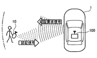
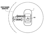
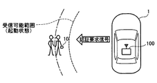
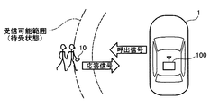
- FIG. 1A is an explanatory diagram when a portable device does not exist within the reach of radio waves from the in-vehicle authentication device
- FIG. 1B is an explanatory diagram when a portable device enters within the reach of radio waves from the in-vehicle authentication device
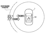
- FIG. 1C is an explanatory diagram when the in-vehicle authentication device authenticates the user's portable device
- FIG. 2 is an explanatory diagram showing the internal structure of the in-vehicle authentication device of this embodiment.
- FIG. 3A is a timing chart showing the state of the portable device when authenticating with the in-vehicle authentication device
- FIG. 3A is a timing chart showing the state of the portable device when authenticating with the in-vehicle authentication device
- FIG. 3B is an explanatory diagram showing a standby state of the portable device
- FIG. 3C is an explanatory diagram showing a startup state of the portable device
- FIG. 4A is an explanatory diagram in a case where the portable device enters a range in which radio waves from the in-vehicle authentication device can be received in a standby state
- FIG. 4B is an explanatory diagram when the portable device falls within a range where radio waves from the in-vehicle authentication device can be received in the activated state
- FIG. 5A is an explanatory diagram when the portable device is between the receivable range in the standby state of the portable device and the receivable range in the activated state of the portable device, and the in-vehicle authentication apparatus transmits a call signal.
- FIG. 5B is an explanatory diagram in the case where there is a portable device between the receivable range in the standby state of the portable device and the receivable range in the activated state of the portable device, and the in-vehicle authentication device transmits an authentication request signal.
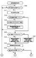
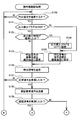
- FIG. 6 is a flowchart of the first half of the portable device authentication process in which the in-vehicle authentication device of this embodiment authenticates the portable device
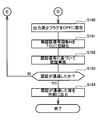
- FIG. 7 is a flowchart showing a part of the second half of the portable device authentication process of this embodiment.
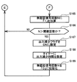
- FIG. 8 is a flowchart showing the remaining part of the second half of the portable device authentication process of this embodiment.
- FIG. 9A is an explanatory diagram when the portable device falls within a range in which radio waves from the in-vehicle authentication device can be received in a standby state
- FIG. 9B is an explanatory diagram when the portable device is between the receivable range in the standby state of the portable device and the receivable range in the activated state of the portable device, and the in-vehicle authentication device transmits the authentication request signal.
- FIG. 9C is an explanatory diagram when the reach of the radio wave from the in-vehicle authentication device is expanded
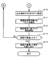
- FIG. 10 is a flowchart of the first half of the mobile device authentication process according to the modification.
- FIG. 11 is a flowchart illustrating a part of the second half of the mobile device authentication process according to the modification.
- FIG. 12 is a flowchart showing the remaining part of the second half of the mobile device authentication process of the modification
- FIG. 13A is an explanatory diagram when the portable device falls within a range in which radio waves from the in-vehicle authentication device can be received in a standby state
- FIG. 13B is an explanatory diagram when the portable device is between the receivable range in the standby state of the portable device and the receivable range in the activated state of the portable device, and the in-vehicle authentication device transmits an authentication request signal.
- FIG. 13C is an explanatory diagram in a case where the reach of radio waves from the in-vehicle authentication device is narrowed.
- FIG. 1A to 1C illustrate a state in which the in-vehicle authentication device 100 of this embodiment mounted on the vehicle 1 authenticates the user's portable device 10.
- the in-vehicle authentication device 100 periodically transmits a call signal (so-called Wake signal) requesting a response signal to be returned to the portable device 10 existing around the vehicle 1.
- a call signal so-called Wake signal
- the call signal does not reach and therefore no response signal is transmitted from the portable device 10.
- FIG. 1A when the portable device 10 does not exist within the reach of the radio wave from the in-vehicle authentication device 100, the call signal does not reach and therefore no response signal is transmitted from the portable device 10.
- FIG. 1A when the portable device 10 does not exist within the reach of the radio wave from the in-vehicle authentication device 100, the call signal does not reach and therefore no response signal is transmitted from the portable device 10.
- FIG. 1A when the portable device 10 does not exist within the reach of the radio wave from the in-vehicle authentication device 100, the call
- the portable device 10 when the portable device 10 enters the reach of the radio wave from the in-vehicle authentication device 100, the portable device 10 receives the call signal from the in-vehicle authentication device 100 and receives a response signal ( So-called Ack signal) is transmitted.
- So-called Ack signal So-called Ack signal
- the in-vehicle authentication apparatus 100 When receiving the response signal, the in-vehicle authentication apparatus 100 recognizes that the portable device 10 has approached the radio wave reachable range, and authenticates the portable device 10 as shown in FIG. An authentication request signal requesting a reply (a so-called Challenge signal) is transmitted. Then, since an authentication signal (a so-called Response signal) is transmitted from the portable device 10, the in-vehicle authentication device 100 authenticates the portable device 10 based on this authentication signal.
- the vehicle-mounted authentication device 100 on the vehicle 1 side needs to periodically transmit a call signal
- the portable device 10 side transmits a response signal or an authentication signal when receiving the call signal or the authentication request signal. Therefore, the power consumption of the portable device 10 can be suppressed.
- the power consumption of the portable device 10 suddenly increases, and it has been observed that the battery is consumed. Therefore, in order to take measures against this point on the vehicle 1 side, the in-vehicle authentication device 100 of the present embodiment has the following internal structure.
- FIG. 2 shows the internal structure of the in-vehicle authentication device 100 of this embodiment.
- the in-vehicle authentication device 100 of this embodiment includes a wireless communication unit 101, a call signal transmission unit 102, an authentication request signal transmission unit 103, an authentication execution unit 104, an unauthenticated signal state detection unit 105, a signal strength.
- a change unit 106 and the like are provided.
- these “units” focus on the functions of the in-vehicle authentication device 100 in order to take measures against the increase in power consumption of the portable device 10 on the in-vehicle authentication device 100 side for the sake of convenience.
- This is a classified abstract concept and does not represent that the in-vehicle authentication device 100 is physically divided into these “parts”. Therefore, these “units” can be realized as a computer program executed by the CPU, can be realized as an electronic circuit including an LSI, or can be realized as a combination thereof.
- the wireless communication unit 101 is connected to the antenna 100a of the in-vehicle authentication device 100, and transmits and receives radio waves by driving the antenna 100a.
- the call signal transmission unit 102 periodically outputs a call signal toward the wireless communication unit 101.
- the wireless communication unit 101 drives the antenna 100a in accordance with the call signal to transmit the radio wave of the call signal wirelessly. Further, when the radio wave of the response signal is returned from the portable device 10 that has received the call signal, the wireless communication unit 101 receives the response signal using the antenna 100 a and outputs the response signal to the authentication request signal transmission unit 103.
- the authentication request signal transmission unit 103 When receiving the response signal from the wireless communication unit 101, the authentication request signal transmission unit 103 outputs the authentication request signal to the wireless communication unit 101. Further, the authentication request signal transmission unit 103 outputs to the unauthenticated signal state detection unit 105 that the authentication request signal has been output.
- the wireless communication unit 101 Upon receiving the authentication request signal from the authentication request signal transmission unit 103, the wireless communication unit 101 transmits the radio wave of the authentication request signal wirelessly by driving the antenna 100a based on the authentication request signal.
- the wireless communication unit 101 receives the authentication signal using the antenna 100 a and outputs it to the authentication execution unit 104.
- the authentication execution unit 104 When the authentication execution unit 104 receives the authentication signal from the wireless communication unit 101, the authentication execution unit 104 outputs a message to that effect to the unauthenticated signal state detection unit 105, and the portable device 10 that has transmitted the authentication signal based on the received authentication signal. Certify.
- the unauthenticated signal state detection unit 105 is connected to the authentication request signal transmission unit 103 and the authentication execution unit 104, and that the authentication request signal is output from the authentication request signal transmission unit 103 (therefore, the radio wave of the authentication request signal is transmitted). Information indicating that an authentication signal has been received from the authentication execution unit 104. Based on these pieces of information, a state in which the authentication signal is not returned although the response signal is returned from the portable device 10 (hereinafter referred to as an unauthenticated signal state) is detected. That is, since the authentication request signal is transmitted when the response signal from the portable device 10 is received, the fact that the authentication request signal is transmitted means that the portable device 10 exists within the radio wave reachable range and the portable device 10 The response signal from the machine 10 is received. And, if the authentication request signal is transmitted in such a situation, it is naturally expected that the authentication signal will be returned, but the state in which the authentication signal cannot be received nevertheless Detect as.
- information indicating that the authentication request signal has been transmitted is output from the authentication request signal transmission unit 103 to the unauthenticated signal state detection unit 105, but before the authentication request signal is transmitted.
- information indicating that a response signal has been received may be output from the authentication request signal transmitting unit 103 to the unauthenticated signal state detecting unit 105 instead of information indicating that the authentication request signal has been transmitted.
- the unauthenticated signal state detection unit 105 receives the information indicating that the authentication signal has been received from the authentication request signal transmitting unit 103 even though the information indicating that the response signal has been received is received from the authentication execution unit 104. A state that does not reach from is detected as an unauthenticated signal state.
- information indicating that the response signal has been received and information indicating that the authentication request signal has been transmitted may be output from the authentication request signal transmitting unit 103 to the unauthenticated signal state detecting unit 105.
- the signal strength changing unit 106 determines whether or not to change the output strength of the authentication request signal. For example, if the unauthenticated signal state continues for a predetermined number of times of 1 or more, it is determined that the output intensity of the authentication request signal is to be increased, and this is output to the wireless communication unit 101. Further, the signal strength changing unit 106 receives information indicating that the authentication request signal has been transmitted from the authentication request signal transmitting unit 103, and the number of times the authentication request signal is transmitted with the output strength increased is a predetermined number. When the upper limit number is reached, the output intensity may be returned to the normal intensity.
- the in-vehicle authentication device 100 of the present embodiment having the internal structure as described above can prevent the battery of the portable device 10 from being suddenly consumed. This is due to the following reasons.
- 3A to 3C show the operation of the portable device 10 when authenticating with the in-vehicle authentication device 100.
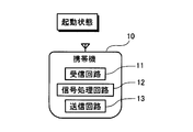
- the portable device 10 transmits and receives radio waves to and from the in-vehicle authentication device 100 while repeating the standby state and the activation state.
- the standby state means that the reception circuit 11 for receiving radio waves operates among the reception circuit 11, the signal processing circuit 12, and the transmission circuit 13 built in the portable device 10.
- the signal processing circuit 12 for processing the received radio wave and the transmission circuit 13 for transmitting the radio wave are not operating. Since the signal processing circuit 12 and the transmission circuit 13 need to be operated only after receiving the radio wave, the operation is stopped until the radio wave is received, thereby suppressing the consumption of the battery.
- the reception circuit 11 is operated so that the call signal from the in-vehicle authentication device 100 can be received whenever it arrives.
- Such a state is a standby state.
- the reception circuit 11 is represented by a solid line, and the signal processing circuit 12 and the transmission circuit 13 are represented by broken lines, although the reception circuit 11 is operating but the signal processing circuit 12 and the transmission circuit 13 are transmitting. The circuit 13 is not operating.
- the portable device 10 will be in an activation state.
- the signal processing circuit 12 and the transmission circuit 13 are operating, and performs predetermined signal processing on the received call signal and transmits a response signal. Can do. After transmitting the response signal, the portable device 10 returns to the standby state as shown in FIG. 3A.
- the portable device 10 is again activated. Then, predetermined signal processing is performed on the authentication request signal, the authentication signal is transmitted, and then the standby state is restored.
- the call signal (so-called Wake signal) is a short signal with a small amount of data, as shown in FIG. 3A, before the signal processing circuit 12 or the transmission circuit 13 starts operating (therefore, before the reception sensitivity is lowered). The reception is completed.
- the authentication request signal (so-called Challenge signal) is a long signal with a large amount of data, reception is not completed before the signal processing circuit 12 or the transmission circuit 13 starts operation. As a result, even if the signal processing circuit 12 and the transmission circuit 13 are operated and the reception sensitivity is lowered, the reception is continued, and in some cases, the authentication request signal cannot be received from the middle.
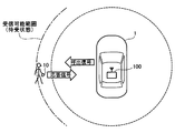
- 4A and 4B show a state where the in-vehicle authentication device 100 authenticates the portable device 10 in a situation where the owner of the portable device 10 approaches the vehicle 1.
- the range indicated by the alternate long and short dash line represents the range in which the radio wave from the in-vehicle authentication device 100 can be received when the portable device 10 is in the standby state
- the range indicated by the broken line is the portable device.
- 10 represents a range in which radio waves can be received when in the activated state.
- the reception sensitivity is lower than that in the standby state. Therefore, the receivable range in the activated state indicated by the broken line is received in the standby state indicated by the alternate long and short dash line. Narrower than possible range.
- the call signal from the in-vehicle authentication device 100 can be received. Since the call signal is a short signal, the reception is completed immediately, and the portable device 10 transmits a response signal toward the in-vehicle authentication device 100. Then, an authentication request signal is transmitted from the in-vehicle authentication device 100.
- the portable device 10 when the owner of the portable device 10 is approaching the vehicle 1, a response signal is transmitted after receiving a call signal from the in-vehicle authentication device 100, and an authentication request signal for the response signal is sent. In the meantime, the portable device 10 moves within the receivable range in the activated state indicated by the broken line. For this reason, as shown in FIG. 4B, the portable device 10 can receive an authentication request signal from the in-vehicle authentication device 100 and send back an authentication signal for the signal.
- FIG. 5A and FIG. 5B show, as an example, a case where the owner of the portable device 10 starts talking in a place where it falls within the receivable range in the standby state.
- reception of a short signal such as a call signal can be completed before the reception sensitivity of the portable device 10 decreases (see FIG. 5A).
- the portable device 10 is switched to an activated state, and the portable device 10 comes out of the receivable range of the authentication request signal in the activated state (See FIG. 5B). For this reason, the in-vehicle authentication apparatus 100 determines that the portable device 10 is gone because the authentication signal does not return even though the authentication request signal is transmitted, and transmits the call signal again.
- this calling signal is a short signal
- the reception can be completed before the portable device 10 switches from the standby state to the activated state, and a response signal is returned from the portable device 10 (see FIG. 5A).
- the authentication request signal is transmitted again from the in-vehicle authentication device 100
- the authentication request signal is a long signal, so that the portable device 10 switches from the standby state to the activated state while receiving the signal, and the reception can be completed. Disappear.
- the in-vehicle authentication device 100 transmits the call signal again.
- the in-vehicle authentication device 100 starts the portable device. 10, the call signal is transmitted many times, and each time the portable device 10 returns a response signal. As a result, it is considered that the battery of the portable device 10 was suddenly consumed. Therefore, the in-vehicle authentication device 100 according to the present embodiment authenticates the portable device 10 by the following method in order to avoid such a situation.
- 6 to 8 show flowcharts of the portable device authentication process in which the in-vehicle authentication device 100 of this embodiment authenticates the portable device 10.
- a call signal is transmitted (S100). Since the call signal is transmitted at a constant cycle, if the elapsed time since the previous call signal was transmitted does not reach the predetermined time, it is determined that the call signal is not transmitted (S100: no). Further, even when the authorized portable device 10 has already been authenticated, it is determined that the call signal is not transmitted (S100: no). When it is determined that the call signal is not transmitted (S100: no), the same determination (S100) is repeated until the call signal is determined to be transmitted.
- a predetermined calling signal is transmitted wirelessly (S101).
- a response signal from the portable device 10 is received (S102). If the portable device 10 is within the reach of the radio wave from the in-vehicle authentication device 100, a response signal should be returned within a certain time after the call signal is transmitted.
- the output increase flag is set to OFF (S103), the number N of unauthenticated signals is initialized to “0”, and the process Returning to the top of the list, it is determined whether or not to transmit a call signal (S100).
- the output increase flag is a flag indicating whether or not to increase the signal output when transmitting the authentication request signal from the standard output.
- the output increase flag is set to OFF in a normal state, but is set to ON when a predetermined condition described later is satisfied.
- the number N of unauthenticated signals is a variable used for counting the number of times that a special state called an unauthenticated signal state has continuously occurred.
- the output increase flag is set to ON. For this reason, when the response signal to the call signal does not return (S102: no), it is not necessary to count the number N of unauthenticated signals and it is not necessary to turn on the output increase flag. In addition, the output increase flag is set to OFF, and the number N of unauthenticated signals is also initialized to “0” (S103, S104).
- the output increase flag is set to ON (S105). As described above, since the output increase flag is set to OFF in the normal state, it is determined as “no” in S105, and the signal strength of the authentication request signal is set to the standard strength (S106). On the other hand, if the output increase flag is set to ON, it is determined as “yes” in S105, and the signal strength of the authentication request signal is set to an increase strength larger than the standard strength (S107). In this embodiment, the increased strength is set to a strength that is about 1 db higher than the standard strength.
- the authentication request signal is a signal that is transmitted when a response signal is received, and the fact that the response signal is received usually means that the portable device 10 is present nearby, and therefore the authentication request signal is normally transmitted. After that, an authentication signal is returned from the portable device 10 during a certain period of time.
- the portable device 10 If the authentication signal is received (S109: yes), the portable device 10 is authenticated based on the authentication signal, but prior to that, the output increase flag is set to OFF (S110 in FIG. 7), and further, The number N of unauthenticated signals is initialized to “0” (S111). That is, as will be described later, the output increase flag and the number N of unauthenticated signals are flags and variables used when the authentication signal cannot be received. Therefore, when the authentication signal can be received (S109: yes), it is necessary to use them. There is no. Therefore, in preparation for the next use, the output increase flag is set to OFF and the number N of unauthenticated signals is initialized to “0” (S110, S111).
- the portable device 10 is authenticated based on the received authentication signal (S112). Then, it is determined whether or not the authentication has passed (S113). If the authentication has passed (S113: yes), the fact that the authentication has passed is output to the outside (S114), and then the above-described portable device authentication process is performed. finish.
- the authentication request signal is a signal that is transmitted when the response signal is returned, and that the response signal is returned means that the portable device 10 is present in a range where the call signal reaches. If so, the authentication signal can be received.
- the portable device 10 moves away from the transmission of the call signal to the transmission of the authentication request signal, or as illustrated in FIGS. 5A and 5B, the portable device 10 receives the call signal. If it stays, it may happen that the authentication signal cannot be received even if the authentication request signal is transmitted. Such a state is an unauthenticated signal state.
- the number N of unauthenticated signals is a variable that counts the number of times that the unauthenticated signal state is continuously generated.
- the threshold number can be set to an appropriate value, but is set to three in this embodiment.
- the process returns to the top of the process and determines again whether or not to transmit a call signal (S100 in FIG. 6). Then, when a call signal is transmitted (S101) and a response signal corresponding to the call signal is received (S102: yes), an authentication request signal is transmitted (S108), and whether or not the authentication signal is received is determined. Judgment is made (S109). As a result, if the authentication signal has not been received (S109: no), after adding “1” again to the number N of unauthenticated signals (S115 in FIG. 8), the number N of unauthenticated signals reaches the threshold number. It is determined whether or not it has been done (S116).
- the output increases.
- the flag is set to OFF (S103, S110 in FIG. 7), and the number N of unauthenticated signals is also initialized to “0” (S104, S111 in FIG. 7).
- the threshold number S116 in FIG. 8: yes
- the upper limit number can be set to an appropriate value larger than the threshold number, but is set to six in this embodiment.
- the output increase flag is set to ON (S118).
- the process returns to the top again and the above-described series of steps is repeated. That is, it is determined whether or not a call signal is transmitted (S100 in FIG. 6), and a call signal is transmitted (S101). If a response signal corresponding to the calling signal is received (S102: yes), it is determined whether or not the output increase flag is set to ON (S105). As a result, it is determined that the output increase flag is set to ON (S105: yes), the signal strength is set to the increased strength (S107), and the authentication request signal is transmitted with the increased strength (S108).
- the authentication request signal is transmitted with a signal strength stronger than the standard, it is possible to avoid a situation where the battery of the portable device 10 is suddenly consumed even in the case illustrated in FIGS. 5A and 5B.
- FIG. 9A to FIG. 9C illustrate how the situation in which the battery of the portable device 10 is suddenly consumed can be avoided by transmitting the authentication request signal with a signal strength stronger than the standard.
- FIG. 9A when the portable device 10 moves toward the vehicle 1, a call from the in-vehicle authentication device 100 is performed at the stage where the portable device 10 has moved into the radio wave receivable range in the standby state. A signal is received and a response signal is returned. At this time, the portable device 10 is switched from the standby state to the activated state. However, when the portable device 10 is activated, the radio wave reception sensitivity is lower than that in the standby state. For this reason, as shown in FIG. 9B, if the owner of the portable device 10 stops at the stage where it has moved to the radio wave receivable range in the standby state, the portable device 10 becomes an in-vehicle authentication device. The authentication request signal from 100 cannot be received.
- the portable device authentication process of this embodiment it is determined that the authentication signal cannot be received (S109: no) even though the authentication request signal is transmitted (S108 in FIG. 6), and the unauthenticated signal “1” is added to the number of times N (S115 in FIG. 8). Thereafter, as in the prior art, the call signal is transmitted again, and if the response signal is returned, the authentication request signal is transmitted (S100 to S108 in FIG. 6), but if the authentication signal cannot be received ( S109: no), “1” is again added to the number N of unauthenticated signals (S115 in FIG. 8).
- the output increase flag is set to ON (S118), and the authentication request signal is transmitted with strong signal strength. (S107 and S108 in FIG. 6).
- the receivable range of the authentication request signal is expanded, so that the authentication request signal can be received even when the portable device 10 is in the activated state, and the authentication signal can be returned.
- the in-vehicle authentication device 100 transmits a call signal many times, and the portable device 10 returns a response signal each time, so that the battery of the portable device 10 is suddenly consumed. It can be avoided.
- the response signal to the call signal returns even though the signal strength of the authentication request signal is increased, but the unauthenticated signal state where the authentication signal for the authentication request signal does not return continues, It is considered that there is a high possibility that some trouble has occurred on the device 10 side and the authentication signal cannot be transmitted. In such a case, if the transmission of the authentication request signal with a large signal strength is repeated, the power consumption of the in-vehicle authentication device 100 increases.
- a predetermined transmission suspension time is set in the timer (S119), and it is determined whether or not the transmission suspension time has passed (S120).
- the transmission suspension time can be set to an appropriate time, but is set to 1 minute in this embodiment.
- the authentication request signal is transmitted with the same strong signal strength while the output increase flag is set to ON.
- the authentication request signal may be transmitted with a signal strength stronger than usual, and the signal strength may be increased each time the authentication request signal is transmitted. In this way, the authentication request signal can be reliably received by the portable device 10 while the authentication request signal is transmitted several times, so that it is possible to reliably avoid a situation where the battery of the portable device 10 is suddenly consumed It becomes possible to do.
- the signal strength of the authentication request signal is increased when the number N of unauthenticated signals reaches a predetermined threshold number. However, it is possible to avoid a situation where the battery of the portable device 10 is suddenly consumed by reducing the signal strength of the calling signal instead of increasing the signal strength of the authentication request signal.
- FIGS. 10 to 12 show flowcharts of the mobile device authentication process of the above-described modification.
- this process weakens the signal strength of the call signal by setting the output decrease flag to ON when the number N of unauthenticated signals reaches a predetermined threshold number.
- the conditions for returning the output reduction flag set to ON to OFF are greatly different.
- the portable device authentication process of the modified example will be briefly described focusing on these differences.
- the portable device authentication process of the modified example first, it is determined whether or not a call signal is transmitted (S150).
- the call signal is transmitted at a constant cycle, and when the elapsed time since the previous call signal was transmitted has not reached the predetermined time, or when the authorized portable device 10 has already been authenticated, the call signal is transmitted. It is determined not to be performed (S150: no), and the standby state is entered by repeating the determination of S150.
- the output reduction flag is a flag indicating whether or not the signal strength of the calling signal is transmitted with a weaker strength than usual.
- the output decrease flag is set to OFF, it is determined as “no” in S151, and the signal strength is set to the standard strength (S155).
- the output decrease time is a time during which the state in which the calling signal is transmitted with a signal strength weaker than usual is continued, and when the output decrease flag is set to ON, the output decrease time is also set. A specific procedure for turning on the output decrease flag and setting the output decrease time will be described in detail later.
- the signal strength of the paging signal is set to be weaker than usual (that is, the decrease strength). (S153). Conversely, if it is determined that the output decrease time has elapsed (S152: yes), after setting the output decrease flag to OFF (S154), the signal strength of the paging signal is set to the standard strength (S155).
- the output decrease flag is set to ON when a predetermined condition described later is satisfied, and while the output decrease flag is set to ON, the call signal is transmitted with a signal strength weaker than usual. After a predetermined output decrease time has elapsed, the output decrease flag is returned to OFF. As a result, the signal strength of the paging signal also returns to the normal strength.
- an authentication request signal is transmitted (S158). Note that the authentication request signal is transmitted at the standard strength regardless of whether the signal strength of the calling signal is set to the standard strength or the reduced strength.
- an authentication signal is received from the portable device 10 (S159). Normally, the authentication signal from the portable device 10 is returned within a certain period of time after the authentication request signal is transmitted.
- the output decrease flag is set to OFF (S160 in FIG. 11)
- the number N of unauthenticated signals is initialized to “0” (S161)
- the authentication signal Based on the above, the portable device 10 is authenticated (S162).
- it is determined whether or not the authentication has passed S163). If the authentication has passed (S163: yes), the fact that the authentication has passed is output to the outside (S164), and then the portable device of the above-described modification example The authentication process ends.
- the number N of unauthenticated signals is set to “1”. Addition is performed (S165 in FIG. 12). As described above, the number N of unauthenticated signals represents the number of times that the unauthenticated signal state occurs continuously.
- FIG. 13A to FIG. 13C illustrate how the situation in which the battery of the portable device 10 is suddenly consumed can be avoided by making the signal strength of the calling signal weaker than usual.
- the situation shown in FIG. 13A to FIG. 13C is similar to the situation shown in FIG. 9A to FIG. 9C, and the owner of the portable device 10 moves toward the vehicle 1 and the call signal from the in-vehicle authentication device 100 This indicates a situation where the user stopped at the stage of receiving the message.
- the portable device 10 when the portable device 10 receives a call signal from the in-vehicle authentication device 100, it returns a response signal. At this time, the portable device 10 switches from the standby state to the activated state, and Reception sensitivity decreases. As a result, as shown in FIG. 13B, the portable device 10 cannot receive the authentication request signal from the in-vehicle authentication device 100 and does not return the authentication signal.
- the receivable range of the call signal from the in-vehicle authentication device 100 is narrowed, and the portable device 10 cannot receive the call signal and does not return a response signal. Since such a situation continues until the output decrease time elapses, the portable device 10 returns a response signal each time the in-vehicle authentication device 100 transmits a call signal, and the battery of the portable device 10 suddenly It is possible to avoid the situation of being exhausted.
- the in-vehicle authentication device 100 continues to transmit the calling signal at a constant period even if the signal strength becomes weak. For this reason, when the owner with the portable device 10 approaches the vehicle 1 again and enters the call signal receivable range, it immediately recognizes the approach of the portable device 10 and authenticates. By transmitting the request signal, authentication of the portable device 10 can be started.
- each unit is expressed as, for example, S100.
- each part can be divided into a plurality of sub-parts, while the plurality of parts can be combined into one part.
- each part configured in this manner can be referred to as a circuit, a device, a module, and a means.
- Each of the above-mentioned plurality of parts or a combination thereof is not only (i) a software part combined with a hardware unit (for example, a computer), but also (ii) hardware (for example, an integrated circuit, As a part of the (wiring logic circuit), it can be realized with or without including the functions of related devices.
- the hardware unit can be configured inside a microcomputer.
Landscapes
- Engineering & Computer Science (AREA)
- Computer Networks & Wireless Communication (AREA)
- Signal Processing (AREA)
- Computer Security & Cryptography (AREA)
- Mechanical Engineering (AREA)
- Physics & Mathematics (AREA)
- General Physics & Mathematics (AREA)
- Lock And Its Accessories (AREA)
- Transceivers (AREA)
- Selective Calling Equipment (AREA)
- Quality & Reliability (AREA)
- Electromagnetism (AREA)
Priority Applications (1)
| Application Number | Priority Date | Filing Date | Title |
|---|---|---|---|
| US16/699,982 US10911953B2 (en) | 2017-06-09 | 2019-12-02 | In-vehicle authentication device and portable device authentication method |
Applications Claiming Priority (2)
| Application Number | Priority Date | Filing Date | Title |
|---|---|---|---|
| JP2017114776A JP6760206B2 (ja) | 2017-06-09 | 2017-06-09 | 車載認証装置、携帯機認証方法 |
| JP2017-114776 | 2017-06-09 |
Related Child Applications (1)
| Application Number | Title | Priority Date | Filing Date |
|---|---|---|---|
| US16/699,982 Continuation US10911953B2 (en) | 2017-06-09 | 2019-12-02 | In-vehicle authentication device and portable device authentication method |
Publications (1)
| Publication Number | Publication Date |
|---|---|
| WO2018225341A1 true WO2018225341A1 (ja) | 2018-12-13 |
Family
ID=64566446
Family Applications (1)
| Application Number | Title | Priority Date | Filing Date |
|---|---|---|---|
| PCT/JP2018/012264 Ceased WO2018225341A1 (ja) | 2017-06-09 | 2018-03-27 | 車載認証装置、携帯機認証方法 |
Country Status (3)
| Country | Link |
|---|---|
| US (1) | US10911953B2 (enExample) |
| JP (1) | JP6760206B2 (enExample) |
| WO (1) | WO2018225341A1 (enExample) |
Families Citing this family (4)
| Publication number | Priority date | Publication date | Assignee | Title |
|---|---|---|---|---|
| CN112085876B (zh) * | 2019-06-14 | 2022-09-30 | 上海华虹计通智能系统股份有限公司 | 一种人员进出管理方法、系统及分体式车载设备 |
| JP7446926B2 (ja) | 2020-06-05 | 2024-03-11 | 株式会社東海理化電機製作所 | 制御装置および制御方法 |
| JP7414648B2 (ja) * | 2020-06-05 | 2024-01-16 | 株式会社東海理化電機製作所 | 制御装置および制御方法 |
| US11463130B1 (en) * | 2021-10-13 | 2022-10-04 | Roku, Inc. | Proving physical possession of internet-of-things (IoT) devices |
Citations (7)
| Publication number | Priority date | Publication date | Assignee | Title |
|---|---|---|---|---|
| JPH11101033A (ja) * | 1997-09-26 | 1999-04-13 | Toyota Motor Corp | 車両用電子キー装置 |
| JP2005112177A (ja) * | 2003-10-08 | 2005-04-28 | Tokai Rika Co Ltd | 制御装置 |
| JP2005325540A (ja) * | 2004-05-12 | 2005-11-24 | Denso Corp | 車両ドア遠隔制御装置 |
| JP2011089264A (ja) * | 2009-10-20 | 2011-05-06 | Tokai Rika Co Ltd | 電子キーシステムの通信パターン切換装置 |
| JP2011223499A (ja) * | 2010-04-14 | 2011-11-04 | Mitsubishi Electric Corp | 無線通信システム |
| JP2016074377A (ja) * | 2014-10-09 | 2016-05-12 | 三菱電機株式会社 | 車両用盗難防止装置 |
| JP2016178617A (ja) * | 2015-03-20 | 2016-10-06 | オムロンオートモーティブエレクトロニクス株式会社 | 車両制御装置 |
Family Cites Families (7)
| Publication number | Priority date | Publication date | Assignee | Title |
|---|---|---|---|---|
| JP4534921B2 (ja) * | 2005-09-13 | 2010-09-01 | 株式会社デンソー | 車載機器制御システム、車両側ユニット及び携帯機 |
| JP2012227586A (ja) | 2011-04-15 | 2012-11-15 | Nippon Soken Inc | 携帯型無線通信装置 |
| JP5974876B2 (ja) * | 2012-12-07 | 2016-08-23 | 株式会社オートネットワーク技術研究所 | 車輌錠制御装置 |
| WO2014104061A1 (ja) * | 2012-12-28 | 2014-07-03 | 株式会社村田製作所 | 積層セラミック電子部品及び該積層セラミック電子部品の製造方法 |
| JP6212973B2 (ja) | 2013-06-19 | 2017-10-18 | 株式会社デンソー | 携帯機探索装置、携帯機探索方法、携帯機探索プログラム |
| EP3037306B1 (en) * | 2013-08-23 | 2018-09-26 | Seoyon Electronics Co., Ltd | Method for preventing relay attack on vehicle smart key system |
| US9710985B2 (en) | 2015-03-20 | 2017-07-18 | Omron Automotive Electronics Co., Ltd. | Vehicle control apparatus |
-
2017
- 2017-06-09 JP JP2017114776A patent/JP6760206B2/ja active Active
-
2018
- 2018-03-27 WO PCT/JP2018/012264 patent/WO2018225341A1/ja not_active Ceased
-
2019
- 2019-12-02 US US16/699,982 patent/US10911953B2/en active Active
Patent Citations (7)
| Publication number | Priority date | Publication date | Assignee | Title |
|---|---|---|---|---|
| JPH11101033A (ja) * | 1997-09-26 | 1999-04-13 | Toyota Motor Corp | 車両用電子キー装置 |
| JP2005112177A (ja) * | 2003-10-08 | 2005-04-28 | Tokai Rika Co Ltd | 制御装置 |
| JP2005325540A (ja) * | 2004-05-12 | 2005-11-24 | Denso Corp | 車両ドア遠隔制御装置 |
| JP2011089264A (ja) * | 2009-10-20 | 2011-05-06 | Tokai Rika Co Ltd | 電子キーシステムの通信パターン切換装置 |
| JP2011223499A (ja) * | 2010-04-14 | 2011-11-04 | Mitsubishi Electric Corp | 無線通信システム |
| JP2016074377A (ja) * | 2014-10-09 | 2016-05-12 | 三菱電機株式会社 | 車両用盗難防止装置 |
| JP2016178617A (ja) * | 2015-03-20 | 2016-10-06 | オムロンオートモーティブエレクトロニクス株式会社 | 車両制御装置 |
Also Published As
| Publication number | Publication date |
|---|---|
| JP6760206B2 (ja) | 2020-09-23 |
| US10911953B2 (en) | 2021-02-02 |
| US20200107194A1 (en) | 2020-04-02 |
| JP2019004202A (ja) | 2019-01-10 |
Similar Documents
| Publication | Publication Date | Title |
|---|---|---|
| CN102542644B (zh) | 电子钥匙系统及电子钥匙 | |
| US10547989B2 (en) | Terminal, vehicle control system, and vehicle control method | |
| CN109552248B (zh) | 终端、车辆控制系统及车辆控制方法 | |
| WO2018225341A1 (ja) | 車載認証装置、携帯機認証方法 | |
| CN108973933B (zh) | 控制系统、车载设备及电子钥匙 | |
| JP2018071213A (ja) | 携帯機器、および携帯機器の制御方法 | |
| JP2020172851A (ja) | 制御装置及び制御システム | |
| CN107444340A (zh) | 无线通信系统 | |
| JP7017049B2 (ja) | 車載機制御装置、車載機制御方法 | |
| CN110710117B (zh) | 便携设备、便携设备的控制方法 | |
| JP2020090159A (ja) | 車載装置、電子キーシステム及び通信方法 | |
| US11059456B2 (en) | In-vehicle authentication device and portable device authentication method | |
| US20230061183A1 (en) | Information processing device, information processing device-equipped vehicle, information processing method, and recording medium recorded with program | |
| CN103368620B (zh) | 便携式设备 | |
| CN108291409B (zh) | 车载器、便携设备以及车辆用无线通信系统 | |
| WO2018116626A1 (ja) | 携帯機検出装置及び携帯機検出方法 | |
| JP7491295B2 (ja) | 車両制御装置、車両、車両制御方法、及びプログラム | |
| JP2020143475A (ja) | 車両制御システム、携帯端末、及び車載装置 | |
| JP6658563B2 (ja) | 通信システム | |
| JP6864118B2 (ja) | 作動制御装置及び作動制御システム | |
| WO2020209254A1 (ja) | 制御装置及び制御システム | |
| US10848954B1 (en) | Conditional repetitive wireless device searching | |
| JP7694309B2 (ja) | 情報処理装置、情報処理方法、及びプログラム | |
| CN116071847A (zh) | 门锁装置 | |
| JP2018035577A (ja) | 通信システム及び携帯機 |
Legal Events
| Date | Code | Title | Description |
|---|---|---|---|
| 121 | Ep: the epo has been informed by wipo that ep was designated in this application |
Ref document number: 18812790 Country of ref document: EP Kind code of ref document: A1 |
|
| NENP | Non-entry into the national phase |
Ref country code: DE |
|
| 122 | Ep: pct application non-entry in european phase |
Ref document number: 18812790 Country of ref document: EP Kind code of ref document: A1 |