WO2018221090A1 - 樹脂モールド金型及び樹脂モールド装置 - Google Patents
樹脂モールド金型及び樹脂モールド装置 Download PDFInfo
- Publication number
- WO2018221090A1 WO2018221090A1 PCT/JP2018/016737 JP2018016737W WO2018221090A1 WO 2018221090 A1 WO2018221090 A1 WO 2018221090A1 JP 2018016737 W JP2018016737 W JP 2018016737W WO 2018221090 A1 WO2018221090 A1 WO 2018221090A1
- Authority
- WO
- WIPO (PCT)
- Prior art keywords
- mold
- block
- resin
- workpiece
- members
- Prior art date
- Legal status (The legal status is an assumption and is not a legal conclusion. Google has not performed a legal analysis and makes no representation as to the accuracy of the status listed.)
- Ceased
Links
Images


Classifications
-
- B—PERFORMING OPERATIONS; TRANSPORTING
- B29—WORKING OF PLASTICS; WORKING OF SUBSTANCES IN A PLASTIC STATE IN GENERAL
- B29C—SHAPING OR JOINING OF PLASTICS; SHAPING OF MATERIAL IN A PLASTIC STATE, NOT OTHERWISE PROVIDED FOR; AFTER-TREATMENT OF THE SHAPED PRODUCTS, e.g. REPAIRING
- B29C33/00—Moulds or cores; Details thereof or accessories therefor
- B29C33/12—Moulds or cores; Details thereof or accessories therefor with incorporated means for positioning inserts, e.g. labels
-
- H—ELECTRICITY
- H01—ELECTRIC ELEMENTS
- H01L—SEMICONDUCTOR DEVICES NOT COVERED BY CLASS H10
- H01L21/00—Processes or apparatus adapted for the manufacture or treatment of semiconductor or solid state devices or of parts thereof
- H01L21/02—Manufacture or treatment of semiconductor devices or of parts thereof
- H01L21/04—Manufacture or treatment of semiconductor devices or of parts thereof the devices having potential barriers, e.g. a PN junction, depletion layer or carrier concentration layer
- H01L21/50—Assembly of semiconductor devices using processes or apparatus not provided for in a single one of the groups H01L21/18 - H01L21/326 or H10D48/04 - H10D48/07 e.g. sealing of a cap to a base of a container
- H01L21/56—Encapsulations, e.g. encapsulation layers, coatings
-
- H—ELECTRICITY
- H01—ELECTRIC ELEMENTS
- H01L—SEMICONDUCTOR DEVICES NOT COVERED BY CLASS H10
- H01L2224/00—Indexing scheme for arrangements for connecting or disconnecting semiconductor or solid-state bodies and methods related thereto as covered by H01L24/00
- H01L2224/01—Means for bonding being attached to, or being formed on, the surface to be connected, e.g. chip-to-package, die-attach, "first-level" interconnects; Manufacturing methods related thereto
- H01L2224/10—Bump connectors; Manufacturing methods related thereto
- H01L2224/15—Structure, shape, material or disposition of the bump connectors after the connecting process
- H01L2224/16—Structure, shape, material or disposition of the bump connectors after the connecting process of an individual bump connector
- H01L2224/161—Disposition
- H01L2224/16151—Disposition the bump connector connecting between a semiconductor or solid-state body and an item not being a semiconductor or solid-state body, e.g. chip-to-substrate, chip-to-passive
- H01L2224/16221—Disposition the bump connector connecting between a semiconductor or solid-state body and an item not being a semiconductor or solid-state body, e.g. chip-to-substrate, chip-to-passive the body and the item being stacked
- H01L2224/16225—Disposition the bump connector connecting between a semiconductor or solid-state body and an item not being a semiconductor or solid-state body, e.g. chip-to-substrate, chip-to-passive the body and the item being stacked the item being non-metallic, e.g. insulating substrate with or without metallisation
-
- H—ELECTRICITY
- H01—ELECTRIC ELEMENTS
- H01L—SEMICONDUCTOR DEVICES NOT COVERED BY CLASS H10
- H01L2224/00—Indexing scheme for arrangements for connecting or disconnecting semiconductor or solid-state bodies and methods related thereto as covered by H01L24/00
- H01L2224/01—Means for bonding being attached to, or being formed on, the surface to be connected, e.g. chip-to-package, die-attach, "first-level" interconnects; Manufacturing methods related thereto
- H01L2224/42—Wire connectors; Manufacturing methods related thereto
- H01L2224/47—Structure, shape, material or disposition of the wire connectors after the connecting process
- H01L2224/48—Structure, shape, material or disposition of the wire connectors after the connecting process of an individual wire connector
- H01L2224/4805—Shape
- H01L2224/4809—Loop shape
- H01L2224/48091—Arched
-
- H—ELECTRICITY
- H01—ELECTRIC ELEMENTS
- H01L—SEMICONDUCTOR DEVICES NOT COVERED BY CLASS H10
- H01L2224/00—Indexing scheme for arrangements for connecting or disconnecting semiconductor or solid-state bodies and methods related thereto as covered by H01L24/00
- H01L2224/73—Means for bonding being of different types provided for in two or more of groups H01L2224/10, H01L2224/18, H01L2224/26, H01L2224/34, H01L2224/42, H01L2224/50, H01L2224/63, H01L2224/71
- H01L2224/732—Location after the connecting process
- H01L2224/73251—Location after the connecting process on different surfaces
- H01L2224/73265—Layer and wire connectors
Definitions
- the present invention relates to a resin mold for resin-molding a workpiece, and a resin mold apparatus including the resin mold.
- a workpiece (molded product) is clamped with a resin mold, and the resin is filled in the cavity while applying resin pressure in that state, and resin molding is performed. Therefore, when filling the cavity with the resin, it is necessary to clamp the workpiece with a sufficient clamping force so that the resin does not leak from the cavity. For this reason, in the resin mold mold, the clamp position of the mold is set in advance according to the thickness of the work, and when the work is clamped, it is clamped by a predetermined clamping force.
- the cavity block that clamps the workpiece is made movable in the mold opening and closing direction, a spring is provided on the back of the cavity block, or the cavity block is hydraulically controlled by pushing the workpiece thickness.
- Patent Document 1 Japanese Patent Application Laid-Open No. 11-58435
- Patent Document 2 Japanese Patent Laid-Open No. 2011-11426) and the like.
- FIG. 17 shows a configuration example of a resin mold die 90 in which the individual movable piece 23 to be abutted has a float structure and an elastic member (for example, a coil spring) 24 is incorporated therein to make the individual movable piece 23 movable.
- work W to some extent is acquired.
- the variation in the height of the chips Wb may increase as the number of chips Wb increases.
- the variation in the height of the chip Wb in the workpiece W may vary depending on the type of product.
- the purpose of exposing the chip Wb differs depending on the type and function of the product, and there are cases where it is necessary to expose all the chips Wb at the time of sealing, and cases where some flash is allowed.
- the thrust (elastic force) of the elastic member 24 is too strong, the tip Wb is damaged, and conversely, if it is too weak, a problem of flashing on the upper surface of the tip Wb is likely to occur. I can't do that.
- the present invention has been made in view of the above circumstances, and in particular, when performing resin molding of a workpiece having a multi-row arrangement in which a plurality of second members are mounted on one first member, the second member is damaged.
- An object of the present invention is to provide a resin mold and a resin mold apparatus that can prevent the occurrence of resin flash on the exposed surface of the second member.
- the present invention solves the above-mentioned problem by a solving means described below as an embodiment.
- the resin mold according to the present invention is a resin mold that resin molds a work in which a plurality of second members are mounted on one first member, and is provided with a work support portion that supports the work. And a second mold provided with a cavity for accommodating the second member of the workpiece, wherein the second mold is configured to expose one end portion at the bottom of the cavity and to mold the second mold.
- a plurality of individual movable pieces that can move in the opening and closing direction and can contact each of the second members, a plurality of rods that respectively push the individual movable pieces, and a resilient force on each of the rods It is necessary to have a plurality of elastic members that act and a block that supports the elastic members.
- the workpiece has a configuration in which the second member is arranged in a matrix in a predetermined X direction on the mounting surface of the first member and a Y direction perpendicular to the X direction, and the X direction or Y
- the adjacent elastic members are arranged such that some areas overlap in a plan view and do not overlap in a side view perpendicular to the one direction, or the X direction and In the respective directions of the Y direction, it is preferable that the adjacent elastic members are arranged so that a part of the elastic members overlap in a plan view and do not overlap in a side view orthogonal to the respective directions.
- the diameter of the elastic member (coil spring) is obtained using a large-diameter elastic member (coil spring) having strength (spring constant) necessary for design.
- Individual movable pieces can be arranged at the following pitch. Therefore, the arrangement of individually movable pieces that can be individually moved can be realized.
- the workpiece has a configuration in which the second member is arranged in a matrix in a predetermined X direction on the mounting surface of the first member and a Y direction orthogonal to the X direction, and as the block,
- Each of the plurality of blocks includes a plurality of blocks, and the elastic members adjacent to each other in one direction of the X direction or the Y direction are arranged in different blocks, or each of the X direction and the Y direction. In this direction, it is preferable that the adjacent elastic members are arranged in different blocks.
- adjacent elastic members do not overlap each other in a partial view in a plan view and in a side view orthogonal to the one direction (that is, in the mold opening / closing direction). It is possible to realize a configuration that is arranged so as not to interfere.
- the workpiece has a configuration in which the second member is arranged in a matrix in a predetermined X direction on the mounting surface of the first member and a Y direction orthogonal to the X direction, and as the block,
- the elastic member provided corresponding to the second member includes a first block, a second block, a third block, and a fourth block that are separately formed and stacked, and the X direction and Y Even when any four adjacent in the direction are extracted, it is preferable that one each is arranged in the first block, the second block, the third block, and the fourth block.
- the rod has a spherical end at the abutting position with the individual movable piece. According to this, not only the variation in the height of the second member but also the influence of the inclination on the individual movable piece can be absorbed even when the upper surface (exposed surface) of the second member is inclined. it can.
- the elastic member is preferably a coil spring formed using a metal material. According to this, it is possible to realize an elastic member having a strength (spring constant) necessary for design in order to give a resilient force to the individual movable piece in a minimum area (projected area in plan view).
- the resin mold apparatus is required to include the resin mold and the film supply mechanism that supplies a release film to the mold surface of the resin mold.
- the individual second member height is increased by using the resin mold die.
- An effect of absorbing the variation in thickness by the movement of each individual movable piece can be obtained.
- a release film excellent in flexibility supplied to the mold surface of the resin mold the effect of absorbing the variation in the height of each second member by the thickness of the release film can be obtained.
- the second member when performing resin molding of a workpiece having a multi-row arrangement in which a plurality of second members (for example, chips) are mounted on one first member (for example, a substrate), the second member is formed. Can be prevented. In addition, it is possible to prevent the resin flash from occurring on the exposed surface of the second member.
- a plurality of second members for example, chips
- FIG. 6 is a sectional view taken along line VI-VI in FIG. 2.
- FIG. 6 shows the schematic (front sectional drawing) which shows the example of the mechanism which adsorb
- FIG. shows the schematic (front sectional drawing) which shows the other example of the resin mold metal mold
- FIG. (front sectional drawing) which shows the other example of the resin mold metal mold
- FIG. 1 is a schematic view (plan view) illustrating an example of a resin mold apparatus 100 including a resin mold 10 according to the first embodiment of the present invention.
- 2 to 5 are schematic views (front sectional views) showing an example of the resin mold 10 according to the first embodiment of the present invention (these figures are also used as operation explanatory diagrams).
- the vertical direction in the resin mold 10 may be described by the top and bottom of the drawing in each drawing.
- a predetermined X direction and a Y direction orthogonal to the X direction are indicated by arrows.
- members having the same function are denoted by the same reference numerals, and repeated description thereof may be omitted.
- the resin molding apparatus 100 is an apparatus that performs resin molding of a workpiece (molded product) W.
- a first mold (lower mold) 20 provided with a pot 35 in which a mold resin (sometimes simply referred to as “resin”) is accommodated, and a second member Wb of the workpiece W are provided.
- a transfer molding apparatus including a resin mold 10 having a second mold (upper mold) 21 provided with a cavity 18 to be accommodated will be described as an example. May be.
- the workpiece W to be formed has a configuration in which the second member Wb is mounted on the first member Wa.
- the first member Wa include various plate-shaped members such as a resin substrate, a ceramic substrate, a metal substrate, a lead frame, a carrier, and a wafer formed in a strip shape.
- the second member Wb include various members such as a semiconductor chip (sometimes simply referred to as “chip”), a MEMS chip, a passive element, a heat sink, and a plate-like member for wiring and heat dissipation. (Hereinafter, these may be referred to as “chips”).
- the workpiece W has a configuration in which the second member Wb is mounted on the first member Wa (flip chip mounting, wire bonding mounting, etc.) and overlapped.
- the workpiece W includes a second member Wb arranged in a matrix in a predetermined X direction on the mounting surface of the first member Wa and a Y direction orthogonal to the X direction. It has a configuration arranged in rows and m columns (one of n and m is an integer of 2 or more).
- one chip or the like may be arranged in n rows and m columns, or a plurality of chips or the like arranged in a predetermined array is regarded as one region. It may be arranged in rows and m columns.
- the resin molding apparatus 100 includes a workpiece supply unit 100A for supplying a workpiece W, a preheating unit 100B for preheating the workpiece W, a press unit 100C for resin molding the workpiece W, and a molded product Wp after the resin molding.
- a molded product storage unit 100D for storage and a transport mechanism 100E are provided.
- the workpiece supply unit 100A includes a stocker 102 that stores a magazine (not shown) that stores workpieces W.
- the workpieces W sent from each magazine by a pusher (not shown) are arranged facing the set table 104 in pairs, for example.
- a tablet supply unit 106 for supplying mold resin (for example, resin tablet T) is provided on the side of the set table 104.
- the workpiece W on the set table 104 is held by a loader 122 of a transfer mechanism 100E described later and transferred to the preheating unit 100B. Further, the resin tablet T of the tablet supply unit 106 is held by the loader 122 and transferred to the press unit 100C.
- the preheating unit 100B includes a heater block 108 that preheats the workpiece W.
- the workpiece W transferred from the workpiece supply unit 100A by the transport mechanism 100E (loader 122) is placed on the heater block 108 and heated (preheated) to a predetermined temperature in that state.
- the preheated workpiece W is held by the loader 122 of the transport mechanism 100E and transferred to the press unit 100C.
- the press unit 100C includes a press device 110 that clamps a preheated work W by opening and closing a resin mold 10 to be described later and resin molds.
- the press device 110 is a known mold-clamping mechanism that pushes the resin mold 10 in the mold opening / closing direction, and a known transfer drive that fills the cavity 18 with the resin melted in the pot 35 of the resin mold 10. It has a mechanism.
- the press device 110 includes a film supply mechanism 112 that supplies the release film F to the mold surface of the resin mold 10.
- the film supply mechanism 112 includes a supply roll 112 a that supplies the release film F to the mold surface (upper mold surface) and a take-up roll 112 b that winds the release film F on both sides of the resin mold 10.
- a film material excellent in heat resistance, ease of peeling, flexibility, and extensibility for example, PTFE, ETFE, PET, FEP, fluorine-impregnated glass cloth, polypropylene, polyvinylidine chloride and the like is preferable. Used.
- the mold surface of the resin mold 10 may not be covered with the release film F.
- the molded product storage unit 100D includes a set unit 114 for setting a molded product Wp after resin molding, a gate break unit 116 for removing unnecessary resin such as a gate from the molded product Wp, and a molded product Wp from which unnecessary resin has been removed. Is provided.
- the molded product Wp is stored in a storage magazine 120, and the magazine 120 in which the molded product is stored is sequentially stored in a stocker 118.
- the transport mechanism 100E includes a loader 122 that carries the workpiece W into the press unit 100C and an unloader 124 that carries the molded product Wp out of the press unit 100C.
- the resin mold apparatus 100 is assembled by connecting the unitized stands.
- Guide units 126 are provided on the back side of each unit, and a guide rail is formed by assembling the guide units 126 so as to be linearly connected.
- Each of the loader 122 and the unloader 124 is provided so as to be linearly movable back and forth along a guide rail from a predetermined position on the guide portion 126 toward the workpiece supply portion 100A, the preheating portion 100B, the press portion 100C, and the molded product storage portion 100D. It has been.
- the configuration of the resin mold apparatus 100 can be changed while maintaining the state where the guide portions 126 are connected to each other.
- the configuration shown in FIG. 1 is an example in which two press devices 110 are installed, but it is also possible to configure a resin molding device (not shown) in which a single press device or a plurality of three or more press devices 110 are connected. It is.
- FIGS. 2 to 5 Schematic views (front sectional views) of the resin mold 10 according to the present embodiment are shown in FIGS. 2 to 5 (these drawings are also used as operation explanatory diagrams).
- the resin mold 10 includes the first mold (lower mold) 20 and the second mold (upper mold) 21.
- the first mold (lower mold) 20 is a movable mold and the second mold (upper mold) 21 is a fixed mold will be described as an example, the present invention is not limited to this configuration.
- the first mold (lower mold) 20 includes a drive transmission mechanism (link mechanism such as a toggle link or a screw shaft) driven by a drive source (electric motor), and a chase (lower The mold is opened and closed by a known mold clamping mechanism that raises and lowers the lower mold movable platen on which the mold chase 33 is placed.
- type) 20 can set a moving speed, a pressurizing force, etc. arbitrarily.
- the first mold (lower mold) 20 has a configuration in which an insert (lower mold insert) 19 and a block (fifth block 15) are fixedly supported by a chase (lower mold chase) 33.
- a work support portion 31 on which a work W (first member Wa side) is placed is provided on the upper surface of the first mold (lower mold) 20 (here, the fifth block 15).
- a plurality of workpiece support portions 31 are provided so that a plurality of workpieces W can be placed thereon.
- the first mold (lower mold) 20 (here, the lower mold insert 19) is provided with a cylindrical pot 35 in which a mold resin (here, resin tablet T) is loaded.
- the upper end surface of the lower mold insert 19 is formed flush with the upper end surface of the pot 35.
- a plunger 36 that moves up and down by a known transfer drive mechanism is provided in the pot 35.
- the plunger 36 employs a multi-plunger structure in which a plurality of plungers 36 are provided on a support block (not shown) corresponding to the plurality of pots 35.
- each plunger 36 is slightly displaced by the elastic force of the elastic member to release an excessive pressing force, and at the time of holding the pressure of the resin tablet T. It is possible to adapt to variations in the amount of resin.
- the plunger 36 is not driven by a known transfer drive mechanism, but is moved up and down in conjunction with mold closing to pressurize the mold resin supplied in the pot 35 or a predetermined mold resin storage area. It is good also as a structure which can be shape
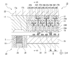
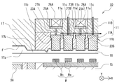
- the second mold (upper mold) 21 has a configuration in which an insert (upper mold insert) 17 and a block are fixedly supported by a chase (upper mold chase) 22.
- the block according to the present embodiment has a configuration in which a plurality of blocks formed as separate bodies (for example, the first block 11 and the second block 12 from the bottom) are stacked.
- the cavity 18 is provided in the block (first block 11), and further, resin flow paths such as an upper mold cull 17 a and an upper mold runner 17 b communicating with the cavity 18 are connected to the upper mold insert 17 and the block ( It is provided in the first block 11).
- the second mold (upper mold) 21 has one end (here, the lower end) exposed at the bottom of the cavity 18 and is movable in the mold opening / closing direction, and one-to-one with each second member Wb.
- a plurality of elastic members 24 in this embodiment, 24A and 24B) that apply elastic force to the rods 27 on a one-on-one basis.
- a relatively small-diameter rod 27 is disposed so as to pass through the gaps between the elastic members 24, the individual movable pieces 23 and the elastic members 24 are connected, and the individual movable pieces 23 are connected to the elastic members 24. It is configured to transmit the elasticity of.
- the support plate 28 is interposed between the rod 27 and the elastic member 24 and fixed.
- the elastic member 24 is a spring (coil spring) formed using a metal material. As described above, the same number of sets of the individual movable pieces 23, the rods 27, and the elastic members 24 are provided for each second member Wb so as to correspond one-to-one.
- adjacent elastic members 24 are arranged in different blocks in one direction of the X direction or the Y direction (described in the example of the X direction in FIG. 2). Yes. That is, the elastic member 24A corresponding to the individual movable piece 23A is supported by the first block 11 and is covered by the upper second block 12, and the elastic member 24B corresponding to the individual movable piece 23B is The upper block is supported by the two blocks 12 and is covered with an upper chase 22 in the upper layer. In other words, the adjacent elastic members 24A and 24B are arranged and accommodated at different height positions in the mold.
- the elastic members 24A and 24B are accommodated and assembled while the first block 11 and the second block 12 are stacked, so that the elastic members 24A and 24B are accommodated at different heights.
- the second mold (upper mold) 21 having the above structure can be manufactured.
- an elastic member is provided on the upper surface of each exposed second member Wb. It is desirable that the individual movable pieces 23 that are individually movable by 24 are arranged so that the variation in the height of each second member Wb is absorbed by the movement of the individual movable pieces 23.
- the pitch of the second member Wb arrangement is equal to or smaller than the diameter of the elastic member (here, the coil spring), the adjacent elastic members 24 interfere with each other when trying to make the movable structure 23 movable.
- each component arrangement that allows individual movement cannot be established, and the entire cavity must be movable integrally. Due to this, if the individual movable piece 23 has an integral structure, variations in the height of the individual second member Wb cannot be absorbed. For this reason, if the variation is large, the second member Wb having a high height is pressed too hard at a certain place and the second member Wb is damaged, or the second member Wb having a low height at a certain place. It is conceivable that the exposed surface of the second member Wb is too weak to cause a resin flash on the upper surface (exposed surface) of the second member Wb.
- the release film F excellent in flexibility, it is possible to exhibit the function of absorbing the variation in the height of the second member Wb to some extent by its elasticity and pressing the exposed surface of the second member Wb.
- the variation in the height of the second member Wb exceeds the thickness of the release film F, the variation in the release film F cannot be absorbed, and it is necessary to increase the thickness of the release film F, which increases the production cost. I could invite you.
- a multistage structure in which the adjacent elastic members 24 are arranged in different blocks in the present embodiment, the first block 11 and the second block 12
- the adjacent elastic members 24 do not overlap with each other when viewed in a side view perpendicular to the one direction. , So as not to interfere in the mold opening / closing direction).
- the individual movable pieces 23 can be arranged at an extremely narrow pitch that is equal to or smaller than the diameter of the elastic member (here, the coil spring) 24, so that the elastic member 24 having a relatively large diameter can be used.
- the rod 27 connected to the elastic member 24 and the support plate 28 to push the individual movable piece 23 has a structure in which the curved tip is pressed against the cavity piece 23 as shown in FIG. It is preferable to do this.
- the end 27a that contacts the individual movable piece 23 is formed in a spherical shape. According to this, not only the variation in the height of the second member Wb but also the case where the upper surface (exposed surface) of the second member Wb is inclined, Therefore, the influence exerted by the inclination of the second member Wb can be absorbed.
- the cavity 18 is usually configured in a Y-direction space similar to the X-direction space in FIG.
- the present invention is not limited to this.
- the Y-direction space is recessed for each individual movable piece 23 corresponding to each second member Wb. It is good also as a structure which the 1st block 11 between the adjacent recessed parts in a Y direction contact
- FIG. 15 enlarged view of the XV part in FIG.
- the first member Wa has a terminal Wa1 on the upper surface
- the second member Wb has a light emitting spot Wb1 on the upper surface
- the work W is supplied to the first mold (lower mold) 20 of the resin mold 10 that has been opened by the loader 122 (see FIG. 1). Further, the release film F is supplied between the second mold (upper mold) and the first mold (lower mold) (above the workpiece W) by the film supply mechanism 112. Further, the resin tablet T is loaded in the pot 35.
- each individual movable piece 23 (23A, 23B) is slidably inserted into each through hole 11a formed in the first block 11, and a downward movement limit is set by the step portion 11b.
- the first block 11 may be formed by a laminated structure of the first block lower step portion 11A and the first block upper step portion 11B.
- the first block 11 (first block lower step portion 11A) is provided with a suction channel 11c that communicates with each through hole 11a and is connected to an external pressure reducing mechanism (not shown). .
- the release film F is not shown in FIGS. 2 to 6 and FIGS. 8 to 12, and the first block lower step portion 11A and the first block upper step portion 11B Are collectively displayed in the first block 11.
- the first mold (lower mold) 20 is raised.
- the individual movable pieces 23 (23A, 23B) provided corresponding to the respective second members Wb are separated from the second member Wb having a high height.
- the contact starts in sequence.
- the individual movable piece 23 (23A, 23B) in contact with the second member Wb moves in the mold opening / closing direction (upward here) while receiving the elastic force of the elastic member 24 (24A, 24B).
- the first mold (lower mold) 20 is further raised to close the resin mold 10.
- the first mold (lower mold) 20 abuts on the second mold (upper mold) 21, and a closed space (cavity 18, upper mold cull 17a, upper mold runner 17b, etc.) is formed therebetween. Is done.
- the closed space is depressurized by a depressurization mechanism (not shown).
- each second member Wb is subjected to a mold closing process.
- individual movable pieces 23 (23A, 23B) sequentially come into contact with the second member Wb.
- the thickness of the bump of the second member Wb from the right is the thickest, the upper surface of the second member Wb is at the highest position. Will be in touch.
- the corresponding elastic members 24 (24A, 24B) are contracted by sequentially abutting from the high second member Wb, so that the individual movable pieces 23 (23A, 23B) are related to the elastic members 24 (24A). , 24B), it is possible to obtain an action of individually moving the optimum amount in the mold opening / closing direction (upward here) while receiving the elastic force. Therefore, since the height variation for each second member Wb can be individually absorbed and the clamping operation can be performed with an appropriate force, damage due to excessive clamping force can be prevented. Incidentally, since the material of the release film F itself is also elastic, the effect of further absorbing the height variation of the second member Wb can be obtained. By using these variation absorbing functions in combination, the height of the second member Wb can be increased. Appropriate clamping can be performed even if the length varies greatly.
- the transfer driving mechanism is operated to push the plunger 36 in the direction of the second mold (upper mold) 21 to melt the mold resin into the upper mold cal 17a and the upper mold runner. It pumps to the cavity 18 through 17b.
- the upper surface of each second member Wb of the workpiece W is pressed and pressed in close contact with the corresponding individual movable piece 23 (23A, 23B) through the release film F with an optimum force. Therefore, it is possible to reliably prevent the resin flush from occurring on the upper surface (exposed surface) of the second member Wb due to insufficient clamping force while preventing damage to the workpiece W due to excessive clamping force.
- the individual movable pieces 23 can be arranged. Accordingly, the individual movable piece 23 that can be individually moved can be installed, the workpiece W can be prevented from being damaged during resin molding, the resin flush can be prevented from occurring on the exposed surface, and the second member Wb mounted on the first member Wa of the workpiece W. It is possible to achieve both a narrow pitch.
- the work W in which the semiconductor chip is mounted on the first member Wa (substrate) as the second member Wb by the flip chip mounting method is described as an example. It is not limited.
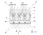
- a sealed object such as the image sensor illustrated in FIG. 8, that is, the second member Wb (image sensor element) is mounted on the first member Wa (substrate) by wire bond connection, Even when the cover glass (transparent member) Wc is placed thereon, the resin molding can be suitably performed.
- the cover glass can be prevented from being damaged, and the cover glass Generation
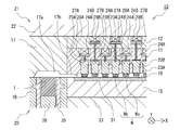
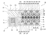
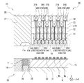
- the workpiece W it is a case in which a resin molded portion is molded on both surfaces (upper and lower surfaces) of the first member Wa (substrate) illustrated in FIG.
- the configuration of the second mold (upper mold) 21 described above is similarly provided to the first mold (lower mold) 20, It is possible to perform resin molding suitably. That is, in the second mold (upper mold) 21, the first block 11 and the second block 12 are provided with individual movable pieces 23A and 23B, elastic members 24A and 24B, rods 27A and 27B, and support plates 28A and 28B.
- the individual movable pieces 23E and 23F are elastically mounted on the fifth block 15 and the sixth block 16 stacked on the lower mold chase 33.
- the members 24E and 24F, the rods 27E and 27F, and the support plates 28E and 28F are provided.
- the resin mold 40 according to the present embodiment has the same basic configuration as the resin mold 10 according to the first embodiment described above, but in particular, the configuration of the second mold (upper mold) 21. Is different.
- the present embodiment will be described focusing on the difference.
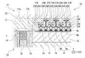
- FIG. 10 to 12 are schematic views (front sectional views) of the resin mold 40 according to the present embodiment.
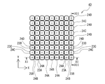
- FIG. 10 is a plan view of the main part of the resin mold 40, and only the individual movable pieces 23 (23A to 23D) and the elastic members 24 (24A to 24D) are illustrated to clarify their arrangement.
- FIG. 11 is a cross-sectional view of the main part of the resin mold 40 (cross-sectional view taken along the line XI-XI in FIG. 10), and is a view seen in a side view orthogonal to the X direction.
- 12 is a cross-sectional view of the principal part of the resin mold 40 (cross-sectional view taken along the line XII-XII in FIG.
- FIG. 10 the individual movable pieces 23C and 23D, the elastic members 24C and 24D, the rods 27C and 27D, and the support plates 28C and 28D in the adjacent rear row are displayed with broken lines, and are displayed with an offset slightly in the left-right direction.
- the arrangement of each component is clarified.
- the individual movable pieces 23A and 23D, the elastic members 24A and 24D, the rods 27A and 27D, and the support plates 28A and 28D in the adjacent rear row are displayed with broken lines and offset slightly in the left-right direction from the actual one.
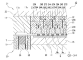
- the resin mold 40 includes an insert (upper mold insert) 17 on a chase (upper mold chase) 22 in a second mold (upper mold) 21.
- the block is provided with the structure supported by the rigid body shape.
- a plurality of blocks formed as separate bodies for example, four blocks of the first block 11, the second block 12, the third block 13, and the fourth block 14 from the bottom
- the resin flow paths such as the cavity 18, the upper mold cull 17a, and the upper mold runner 17b have the same configuration as that of the first embodiment.
- a plurality of individual movable pieces 23 in the present embodiment, 23A, 23B, 23C, and the like
- a plurality of rods 27 in this embodiment, 27A, 27B, 27C, and 27D
- a plurality of elastic members (coil springs) 24 24A, 24B, 24C, 24D in the present embodiment to be acted are provided.
- blocks in which the adjacent elastic members 24 are different in the X direction and the Y direction (in the present embodiment, the first block). 11, the second block 12, the third block 13, and the fourth block 14). That is, the elastic member 24C corresponding to the individual movable piece 23C is supported by the first block 11 and covered with the second block 12 of the upper layer, and the elastic member 24D corresponding to the individual movable piece 23D is the first one.
- the elastic member 24A is supported by the second block 12 and covered by the upper third block 13, and the elastic member 24A corresponding to the individual movable piece 23A is supported by the third block 13 and the upper fourth block 14.
- the elastic member 24B corresponding to the individual movable piece 23B is supported by the fourth block 14 and is covered by the upper chase 22 of the upper layer.
- a multi-stage structure in which the adjacent elastic members 24 are arranged in different blocks in the present embodiment, the first block 11, the second block 12, the third block 13, and the fourth block 14
- adjacent elastic members 24 do not overlap each other in a partial view in a plan view and in a side view perpendicular to the respective directions (that is, interference in the mold opening / closing direction).
- the individual movable pieces 23 can be arranged at a pitch equal to or less than the diameter of the elastic member (here, the coil spring) 24, so that the relative diameter of the elastic force (here, the spring constant) necessary for design is provided.
- the elastic member 24 provided corresponding to the second member Wb even if any four adjacent in the X direction and the Y direction are extracted, the first block 11 and the second block 11 respectively.
- the four adjacent elastic members 24, 24, 24, 24 can be arranged such that a part of the regions overlap in plan view. Accordingly, since the interval between the adjacent individual movable pieces 23 can be further reduced in both the X direction and the Y direction, a plurality of second members Wb are mounted on one first member Wa (substrate).
- the interval between the adjacent second members Wb can be further reduced in both the X direction and the Y direction.
- the pitch of the second member Wb can be further reduced as compared with the first embodiment, and the use area of the first member Wa and the waste of the mold resin can be further reduced to obtain more molded products. Obtainable. Thereby, the production cost of a molded product can also be reduced.
- the basic resin mold operation in the resin mold 40 is the same as that of the resin mold 10 according to the first embodiment described above, and a description thereof will be omitted.
- the elastic member having a large strength (spring constant) necessary for design is used.
- the individual movable pieces can be arranged at a pitch equal to or less than the diameter of the coil spring.
- the present invention is not limited to the embodiments described above, and various modifications can be made without departing from the present invention.
- it is good also as a compression molding die structure which turned the structure as shown in FIGS. 2-6 upside down.
- a mold resin pressure region may be provided in a part of the cavity, and the resin may be filled after the second member Wb is clamped.
Landscapes
- Engineering & Computer Science (AREA)
- Microelectronics & Electronic Packaging (AREA)
- Condensed Matter Physics & Semiconductors (AREA)
- General Physics & Mathematics (AREA)
- Manufacturing & Machinery (AREA)
- Computer Hardware Design (AREA)
- Physics & Mathematics (AREA)
- Power Engineering (AREA)
- Mechanical Engineering (AREA)
- Moulds For Moulding Plastics Or The Like (AREA)
- Encapsulation Of And Coatings For Semiconductor Or Solid State Devices (AREA)
- Casting Or Compression Moulding Of Plastics Or The Like (AREA)
- Injection Moulding Of Plastics Or The Like (AREA)
Applications Claiming Priority (2)
| Application Number | Priority Date | Filing Date | Title |
|---|---|---|---|
| JP2017-110471 | 2017-06-02 | ||
| JP2017110471A JP6891048B2 (ja) | 2017-06-02 | 2017-06-02 | 樹脂モールド金型及び樹脂モールド装置 |
Publications (1)
| Publication Number | Publication Date |
|---|---|
| WO2018221090A1 true WO2018221090A1 (ja) | 2018-12-06 |
Family
ID=64456267
Family Applications (1)
| Application Number | Title | Priority Date | Filing Date |
|---|---|---|---|
| PCT/JP2018/016737 Ceased WO2018221090A1 (ja) | 2017-06-02 | 2018-04-25 | 樹脂モールド金型及び樹脂モールド装置 |
Country Status (3)
| Country | Link |
|---|---|
| JP (1) | JP6891048B2 (enExample) |
| TW (1) | TWI750369B (enExample) |
| WO (1) | WO2018221090A1 (enExample) |
Cited By (1)
| Publication number | Priority date | Publication date | Assignee | Title |
|---|---|---|---|---|
| EP4052879A1 (de) * | 2021-03-01 | 2022-09-07 | Wickert Maschinenbau GmbH | Vorrichtung und verfahren zum einlegen vorgefertigter teile in ein formwerkzeug einer presse sowie presse mit einer solchen vorrichtung |
Families Citing this family (7)
| Publication number | Priority date | Publication date | Assignee | Title |
|---|---|---|---|---|
| JP7121763B2 (ja) * | 2020-02-14 | 2022-08-18 | アピックヤマダ株式会社 | 樹脂モールド装置及び樹脂モールド方法 |
| JP7360368B2 (ja) * | 2020-08-18 | 2023-10-12 | Towa株式会社 | 樹脂成形装置及び樹脂成形品の製造方法 |
| JP7576333B2 (ja) * | 2021-12-06 | 2024-10-31 | アピックヤマダ株式会社 | 樹脂封止装置及び封止金型 |
| JP2023105331A (ja) * | 2022-01-19 | 2023-07-31 | アピックヤマダ株式会社 | 樹脂封止装置 |
| JP2025010701A (ja) * | 2023-07-10 | 2025-01-23 | アピックヤマダ株式会社 | 実装装置及び実装方法 |
| JP7538972B1 (ja) | 2024-02-07 | 2024-08-22 | 日機装株式会社 | 加圧装置 |
| JP7581554B1 (ja) | 2024-04-18 | 2024-11-12 | 日機装株式会社 | 加圧装置 |
Citations (8)
| Publication number | Priority date | Publication date | Assignee | Title |
|---|---|---|---|---|
| JPH11126787A (ja) * | 1997-10-24 | 1999-05-11 | Towa Corp | 電子部品の樹脂封止成形方法及び金型 |
| JP2002254481A (ja) * | 2001-03-01 | 2002-09-11 | Nec Corp | 樹脂モールド金型及び樹脂モールドパッケージの製造方法 |
| JP2004119803A (ja) * | 2002-09-27 | 2004-04-15 | Towa Corp | 電子部品の樹脂注入方法及び装置 |
| JP2010201903A (ja) * | 2009-03-06 | 2010-09-16 | Maxell Seiki Kk | 薄膜状インサート成形品の製造方法、および薄膜状インサート成形品 |
| JP2012200935A (ja) * | 2011-03-24 | 2012-10-22 | Apic Yamada Corp | モールド金型及びこれを用いた樹脂モールド装置並びに圧着装置 |
| JP2013147026A (ja) * | 2011-12-22 | 2013-08-01 | Daikin Industries Ltd | 離型フィルム |
| WO2015159743A1 (ja) * | 2014-04-18 | 2015-10-22 | アピックヤマダ株式会社 | 樹脂モールド金型および樹脂モールド方法 |
| JP2016155301A (ja) * | 2015-02-25 | 2016-09-01 | 新日本無線株式会社 | モールド成型装置及びモールド成型方法 |
Family Cites Families (5)
| Publication number | Priority date | Publication date | Assignee | Title |
|---|---|---|---|---|
| JP4834407B2 (ja) * | 2006-01-17 | 2011-12-14 | アピックヤマダ株式会社 | 樹脂モールド方法および樹脂モールド装置 |
| JP4875927B2 (ja) * | 2006-06-02 | 2012-02-15 | アピックヤマダ株式会社 | 樹脂モールド装置 |
| JP5770537B2 (ja) * | 2011-06-02 | 2015-08-26 | 矢崎総業株式会社 | インサート成形用金型及びカラーのインサート成形方法 |
| JP6062810B2 (ja) * | 2013-06-14 | 2017-01-18 | アピックヤマダ株式会社 | 樹脂モールド金型及び樹脂モールド装置 |
| JP5854096B1 (ja) * | 2014-07-29 | 2016-02-09 | 第一精工株式会社 | 樹脂封止装置 |
-
2017
- 2017-06-02 JP JP2017110471A patent/JP6891048B2/ja active Active
-
2018
- 2018-04-25 WO PCT/JP2018/016737 patent/WO2018221090A1/ja not_active Ceased
- 2018-05-03 TW TW107115086A patent/TWI750369B/zh active
Patent Citations (8)
| Publication number | Priority date | Publication date | Assignee | Title |
|---|---|---|---|---|
| JPH11126787A (ja) * | 1997-10-24 | 1999-05-11 | Towa Corp | 電子部品の樹脂封止成形方法及び金型 |
| JP2002254481A (ja) * | 2001-03-01 | 2002-09-11 | Nec Corp | 樹脂モールド金型及び樹脂モールドパッケージの製造方法 |
| JP2004119803A (ja) * | 2002-09-27 | 2004-04-15 | Towa Corp | 電子部品の樹脂注入方法及び装置 |
| JP2010201903A (ja) * | 2009-03-06 | 2010-09-16 | Maxell Seiki Kk | 薄膜状インサート成形品の製造方法、および薄膜状インサート成形品 |
| JP2012200935A (ja) * | 2011-03-24 | 2012-10-22 | Apic Yamada Corp | モールド金型及びこれを用いた樹脂モールド装置並びに圧着装置 |
| JP2013147026A (ja) * | 2011-12-22 | 2013-08-01 | Daikin Industries Ltd | 離型フィルム |
| WO2015159743A1 (ja) * | 2014-04-18 | 2015-10-22 | アピックヤマダ株式会社 | 樹脂モールド金型および樹脂モールド方法 |
| JP2016155301A (ja) * | 2015-02-25 | 2016-09-01 | 新日本無線株式会社 | モールド成型装置及びモールド成型方法 |
Cited By (1)
| Publication number | Priority date | Publication date | Assignee | Title |
|---|---|---|---|---|
| EP4052879A1 (de) * | 2021-03-01 | 2022-09-07 | Wickert Maschinenbau GmbH | Vorrichtung und verfahren zum einlegen vorgefertigter teile in ein formwerkzeug einer presse sowie presse mit einer solchen vorrichtung |
Also Published As
| Publication number | Publication date |
|---|---|
| JP6891048B2 (ja) | 2021-06-18 |
| JP2018202740A (ja) | 2018-12-27 |
| TWI750369B (zh) | 2021-12-21 |
| TW201902658A (zh) | 2019-01-16 |
Similar Documents
| Publication | Publication Date | Title |
|---|---|---|
| WO2018221090A1 (ja) | 樹脂モールド金型及び樹脂モールド装置 | |
| KR102301482B1 (ko) | 수지 몰드 금형 및 수지 몰드 장치 | |
| TWI641471B (zh) | Resin molding die and resin molding method | |
| JP6273340B2 (ja) | 樹脂モールド金型及び樹脂モールド装置 | |
| WO2017081882A1 (ja) | 樹脂封止装置及び樹脂封止方法 | |
| JP7312421B2 (ja) | モールド金型、樹脂モールド装置及び樹脂モールド方法並びに搬送具 | |
| KR102527948B1 (ko) | 수지 성형 장치 및 수지 성형품의 제조 방법 | |
| JP7029342B2 (ja) | モールド金型、樹脂モールド装置及び樹脂モールド方法 | |
| JP6822901B2 (ja) | 樹脂モールド金型及び樹脂モールド装置 | |
| JP7121705B2 (ja) | 樹脂モールド金型 | |
| JP7644497B2 (ja) | 樹脂封止装置及び封止金型 | |
| TWI648140B (zh) | 使用微柱封裝位於載體上的電子元件的模具、模壓機以及方法 | |
| JP5694486B2 (ja) | 樹脂封止装置 | |
| TWI853274B (zh) | 壓縮成形裝置 | |
| JP7068144B2 (ja) | 樹脂モールドプレス装置及び樹脂モールド装置 | |
| TWI900142B (zh) | 壓縮成形裝置及壓縮成形方法 | |
| EP4661063A1 (en) | Sealing resin used for compression molding, and forming method for same | |
| EP4659930A1 (en) | Compression-molding device and compression-molding method | |
| JP2025049905A (ja) | 圧縮成形装置及び圧縮成形方法 | |
| WO2025057660A1 (ja) | 樹脂封止装置及び樹脂封止方法 | |
| JP2024139406A (ja) | 圧縮成形装置及び圧縮成形方法 |
Legal Events
| Date | Code | Title | Description |
|---|---|---|---|
| 121 | Ep: the epo has been informed by wipo that ep was designated in this application |
Ref document number: 18809011 Country of ref document: EP Kind code of ref document: A1 |
|
| NENP | Non-entry into the national phase |
Ref country code: DE |
|
| 122 | Ep: pct application non-entry in european phase |
Ref document number: 18809011 Country of ref document: EP Kind code of ref document: A1 |