WO2018216530A1 - 全方向移動装置及びその姿勢制御方法 - Google Patents
全方向移動装置及びその姿勢制御方法 Download PDFInfo
- Publication number
- WO2018216530A1 WO2018216530A1 PCT/JP2018/018611 JP2018018611W WO2018216530A1 WO 2018216530 A1 WO2018216530 A1 WO 2018216530A1 JP 2018018611 W JP2018018611 W JP 2018018611W WO 2018216530 A1 WO2018216530 A1 WO 2018216530A1
- Authority
- WO
- WIPO (PCT)
- Prior art keywords
- chassis
- vehicle body
- posture
- wheel
- omnidirectional
- Prior art date
- Legal status (The legal status is an assumption and is not a legal conclusion. Google has not performed a legal analysis and makes no representation as to the accuracy of the status listed.)
- Ceased
Links
Images


Classifications
-
- G—PHYSICS
- G05—CONTROLLING; REGULATING
- G05D—SYSTEMS FOR CONTROLLING OR REGULATING NON-ELECTRIC VARIABLES
- G05D1/00—Control of position, course, altitude or attitude of land, water, air or space vehicles, e.g. using automatic pilots
- G05D1/08—Control of attitude, i.e. control of roll, pitch, or yaw
- G05D1/0891—Control of attitude, i.e. control of roll, pitch, or yaw specially adapted for land vehicles
-
- B—PERFORMING OPERATIONS; TRANSPORTING
- B60—VEHICLES IN GENERAL
- B60B—VEHICLE WHEELS; CASTORS; AXLES FOR WHEELS OR CASTORS; INCREASING WHEEL ADHESION
- B60B19/00—Wheels not otherwise provided for or having characteristics specified in one of the subgroups of this group
- B60B19/003—Multidirectional wheels
-
- B—PERFORMING OPERATIONS; TRANSPORTING
- B60—VEHICLES IN GENERAL
- B60B—VEHICLE WHEELS; CASTORS; AXLES FOR WHEELS OR CASTORS; INCREASING WHEEL ADHESION
- B60B19/00—Wheels not otherwise provided for or having characteristics specified in one of the subgroups of this group
- B60B19/12—Roller-type wheels
-
- B—PERFORMING OPERATIONS; TRANSPORTING
- B60—VEHICLES IN GENERAL
- B60G—VEHICLE SUSPENSION ARRANGEMENTS
- B60G13/00—Resilient suspensions characterised by arrangement, location or type of vibration dampers
- B60G13/001—Arrangements for attachment of dampers
- B60G13/003—Arrangements for attachment of dampers characterised by the mounting on the vehicle body or chassis of the damper unit
-
- B—PERFORMING OPERATIONS; TRANSPORTING
- B60—VEHICLES IN GENERAL
- B60G—VEHICLE SUSPENSION ARRANGEMENTS
- B60G17/00—Resilient suspensions having means for adjusting the spring or vibration-damper characteristics, for regulating the distance between a supporting surface and a sprung part of vehicle or for locking suspension during use to meet varying vehicular or surface conditions, e.g. due to speed or load
- B60G17/015—Resilient suspensions having means for adjusting the spring or vibration-damper characteristics, for regulating the distance between a supporting surface and a sprung part of vehicle or for locking suspension during use to meet varying vehicular or surface conditions, e.g. due to speed or load the regulating means comprising electric or electronic elements
- B60G17/016—Resilient suspensions having means for adjusting the spring or vibration-damper characteristics, for regulating the distance between a supporting surface and a sprung part of vehicle or for locking suspension during use to meet varying vehicular or surface conditions, e.g. due to speed or load the regulating means comprising electric or electronic elements characterised by their responsiveness, when the vehicle is travelling, to specific motion, a specific condition, or driver input
-
- B—PERFORMING OPERATIONS; TRANSPORTING
- B60—VEHICLES IN GENERAL
- B60G—VEHICLE SUSPENSION ARRANGEMENTS
- B60G17/00—Resilient suspensions having means for adjusting the spring or vibration-damper characteristics, for regulating the distance between a supporting surface and a sprung part of vehicle or for locking suspension during use to meet varying vehicular or surface conditions, e.g. due to speed or load
- B60G17/015—Resilient suspensions having means for adjusting the spring or vibration-damper characteristics, for regulating the distance between a supporting surface and a sprung part of vehicle or for locking suspension during use to meet varying vehicular or surface conditions, e.g. due to speed or load the regulating means comprising electric or electronic elements
- B60G17/019—Resilient suspensions having means for adjusting the spring or vibration-damper characteristics, for regulating the distance between a supporting surface and a sprung part of vehicle or for locking suspension during use to meet varying vehicular or surface conditions, e.g. due to speed or load the regulating means comprising electric or electronic elements characterised by the type of sensor or the arrangement thereof
- B60G17/01908—Acceleration or inclination sensors
-
- B—PERFORMING OPERATIONS; TRANSPORTING
- B60—VEHICLES IN GENERAL
- B60G—VEHICLE SUSPENSION ARRANGEMENTS
- B60G21/00—Interconnection systems for two or more resiliently-suspended wheels, e.g. for stabilising a vehicle body with respect to acceleration, deceleration or centrifugal forces
-
- B—PERFORMING OPERATIONS; TRANSPORTING
- B62—LAND VEHICLES FOR TRAVELLING OTHERWISE THAN ON RAILS
- B62D—MOTOR VEHICLES; TRAILERS
- B62D27/00—Connections between superstructure or understructure sub-units
- B62D27/02—Connections between superstructure or understructure sub-units rigid
-
- B—PERFORMING OPERATIONS; TRANSPORTING
- B62—LAND VEHICLES FOR TRAVELLING OTHERWISE THAN ON RAILS
- B62D—MOTOR VEHICLES; TRAILERS
- B62D37/00—Stabilising vehicle bodies without controlling suspension arrangements
-
- B—PERFORMING OPERATIONS; TRANSPORTING
- B62—LAND VEHICLES FOR TRAVELLING OTHERWISE THAN ON RAILS
- B62D—MOTOR VEHICLES; TRAILERS
- B62D51/00—Motor vehicles characterised by the driver not being seated
- B62D51/02—Motor vehicles characterised by the driver not being seated the driver standing in the vehicle
-
- B—PERFORMING OPERATIONS; TRANSPORTING
- B62—LAND VEHICLES FOR TRAVELLING OTHERWISE THAN ON RAILS
- B62D—MOTOR VEHICLES; TRAILERS
- B62D57/00—Vehicles characterised by having other propulsion or other ground- engaging means than wheels or endless track, alone or in addition to wheels or endless track
-
- B—PERFORMING OPERATIONS; TRANSPORTING
- B62—LAND VEHICLES FOR TRAVELLING OTHERWISE THAN ON RAILS
- B62D—MOTOR VEHICLES; TRAILERS
- B62D61/00—Motor vehicles or trailers, characterised by the arrangement or number of wheels, not otherwise provided for, e.g. four wheels in diamond pattern
-
- B—PERFORMING OPERATIONS; TRANSPORTING
- B62—LAND VEHICLES FOR TRAVELLING OTHERWISE THAN ON RAILS
- B62K—CYCLES; CYCLE FRAMES; CYCLE STEERING DEVICES; RIDER-OPERATED TERMINAL CONTROLS SPECIALLY ADAPTED FOR CYCLES; CYCLE AXLE SUSPENSIONS; CYCLE SIDECARS, FORECARS, OR THE LIKE
- B62K17/00—Cycles not otherwise provided for
-
- B—PERFORMING OPERATIONS; TRANSPORTING
- B60—VEHICLES IN GENERAL
- B60B—VEHICLE WHEELS; CASTORS; AXLES FOR WHEELS OR CASTORS; INCREASING WHEEL ADHESION
- B60B2900/00—Purpose of invention
- B60B2900/30—Increase in
- B60B2900/331—Safety or security
- B60B2900/3312—Safety or security during regular use
-
- B—PERFORMING OPERATIONS; TRANSPORTING
- B60—VEHICLES IN GENERAL
- B60G—VEHICLE SUSPENSION ARRANGEMENTS
- B60G2400/00—Indexing codes relating to detected, measured or calculated conditions or factors
- B60G2400/05—Attitude
- B60G2400/051—Angle
-
- B—PERFORMING OPERATIONS; TRANSPORTING
- B60—VEHICLES IN GENERAL
- B60G—VEHICLE SUSPENSION ARRANGEMENTS
- B60G2400/00—Indexing codes relating to detected, measured or calculated conditions or factors
- B60G2400/05—Attitude
- B60G2400/052—Angular rate
-
- B—PERFORMING OPERATIONS; TRANSPORTING
- B60—VEHICLES IN GENERAL
- B60G—VEHICLE SUSPENSION ARRANGEMENTS
- B60G2400/00—Indexing codes relating to detected, measured or calculated conditions or factors
- B60G2400/10—Acceleration; Deceleration
-
- B—PERFORMING OPERATIONS; TRANSPORTING
- B60—VEHICLES IN GENERAL
- B60G—VEHICLE SUSPENSION ARRANGEMENTS
- B60G2500/00—Indexing codes relating to the regulated action or device
Definitions
- the present invention relates to an omnidirectional moving device and a posture control method thereof.
- Japanese Patent No. 3070015 discloses an omnidirectional moving device (omnidirectional moving vehicle).
- this omnidirectional movement device since a single sphere (rotary body) is rotatably mounted on the frame, the frame is statically unstable.
- the sphere is rotated to travel and the posture of the traveling frame is stably maintained, so that the frame is dynamically stabilized.
- the contact with a spherical body and a running path (ground) is a point contact. That is, the contact area between the sphere and the travel path is small, and the sphere cannot obtain a sufficient grip force during travel.
- the present invention provides an omnidirectional movement device capable of dynamically stabilizing a statically unstable vehicle body, improving propulsive force, and improving quietness, and its attitude Provide a control method.
- an omnidirectional movement device includes a chassis having a plurality of wheels that can move in all directions, a vehicle body disposed on the chassis, a chassis, A universal joint that connects the vehicle body so that the posture of the vehicle body can change with respect to the vehicle body, and a posture stabilization system that moves the vehicle body in the direction in which the vehicle body posture changes, and that maintains the vehicle body posture stably. It is equipped with.
- the omnidirectional mobile device includes a chassis and a vehicle body disposed on the chassis.
- a wheel is disposed on the chassis, and the wheel is movable in all directions.
- the omnidirectional movement device includes a universal joint and a posture stabilization system, and a plurality of wheels are arranged on the chassis.
- the universal joint connects the chassis and the vehicle body so that the posture of the vehicle body can be changed with respect to the vehicle body.
- all of these wheels are grounded to the travel path.
- the posture of the chassis changes in accordance with the inclination of the road surface of the traveling road.
- the attitude of the vehicle body is not linked to the attitude of the chassis. That is, since the vehicle body is simply connected to the chassis via a universal joint, it is statically unstable with respect to the chassis.
- the attitude stabilization system moves the chassis in the direction in which the attitude of the vehicle body has changed, and maintains the attitude of the vehicle body stably.
- the posture stabilization system since the posture stabilization system is provided, the posture of the vehicle body is stably maintained when the chassis is moved, and the vehicle body is dynamically stabilized. Since a plurality of grounding points between the wheel and the traveling road are provided, the ground contact area between the wheel and the traveling road is increased, and the wheel can obtain a sufficient grip force when moving. Since a sufficient grip force can be obtained, even if dust or liquid on the traveling road adheres to the wheel surface, slippage of the wheel with respect to the traveling road is reduced. Furthermore, since a plurality of wheels are in contact with the traveling road, the vibration transmitted to the chassis and the vehicle body when moving on a step or rough terrain is smaller than when a single sphere is in contact with the traveling road.
- the number of the universal joints is 2 in the omnidirectional mobile device according to the first embodiment.
- the vehicle body since the number of the universal joint is 2, the vehicle body has two degrees of freedom with respect to the chassis, and the posture of the vehicle body changes in these two directions. Can be made. For example, a degree of freedom to rotate around the first rotation axis with the Y axis direction of the three-dimensional coordinates as the first rotation axis, and a degree of freedom to rotate around the second rotation axis with the X axis direction as the second rotation axis.
- the posture of the vehicle body can be changed within the range of the two degrees of freedom.
- the degree of freedom of rotation around an axis having the Z axis direction as the third rotation axis is not set. For this reason, when the chassis is turned, the vehicle body can be turned following the turning of the chassis.
- the universal joint is supported on the upper part of the chassis, and one of the movement directions of the chassis is defined as the first axial direction.
- a first rotating shaft, a second rotating shaft supported by the lower part of the vehicle body and having a second axis direction that is another one of the moving directions of the chassis and intersecting the first axis direction, and the first rotating shaft And a spider that is rotatable about the second rotation axis.
- a universal joint is provided with a 1st rotating shaft, a 2nd rotating shaft, and a spider.
- the first rotation shaft is supported on the upper part of the chassis, and one of the movement directions of the chassis is defined as the first axis direction.
- the Y axis direction exemplified in the second embodiment is the first axis direction.
- the second rotating shaft is supported at the lower part of the vehicle body, and is a second axis direction that is another one of the moving directions of the chassis and intersects the first axis direction.
- the X axis direction orthogonal to the Y axis direction exemplified in the second embodiment is the second axis direction.
- the spider is rotatable about the first rotation axis and is rotatable about the second rotation axis. For this reason, since the spider can be rotated around the two rotation axes of the first rotation axis and the second rotation axis, a universal joint having two pairs can be easily realized.
- the posture stabilizing system includes a motor provided on the chassis, A drive unit is provided that includes a speed reducer that is provided on the chassis and that reduces the rotational driving force of the motor and transmits it to the wheel, and a servo amplifier that is provided on the vehicle body and is connected to the motor to drive the motor.
- the posture stabilization system includes the drive unit.
- the drive unit includes a motor, a speed reducer, and a servo amplifier.
- the motor is provided on the chassis.
- the speed reducer is provided on the chassis and decelerates the rotational driving force of the motor and transmits it to the wheel.
- the servo amplifier is provided on the vehicle body and is connected to the motor to drive the motor. Since the drive unit including these components is provided, in the attitude stabilization system, the attitude of the vehicle body is stably maintained when the chassis is moved, and the vehicle body can be dynamically stabilized.
- the wheel is at least one of an omni wheel and a mecanum wheel.
- the wheel is at least one of an omni wheel and a mecanum wheel.
- the omni wheel is configured by arranging a plurality of rollers that rotate freely around the circumference of the drive wheel with the circumferential direction as the axial direction.
- the Mecanum wheel is configured by arranging a plurality of rollers that freely rotate on the circumference of the drive wheel with the direction inclined with respect to the rotation axis of the drive wheel as the axial direction. Therefore, regardless of which wheel is used, the chassis can be moved in the direction of movement due to the rotation of the roller in addition to the direction of movement due to the rotation of the drive wheel, so that it can move in all directions on the plane.
- a mobile device can be realized.
- the posture stabilization system includes an angle detection unit that acquires the rotation angle of the motor, the posture angle of the vehicle body, and the vehicle body. Based on the posture angle detection unit that acquires the angular velocity of the vehicle, the rotation angle acquired by the angle detection unit, and the posture angle and angular velocity acquired by the posture angle detection unit, the motion state of the vehicle body that stably maintains the posture is determined.
- a control unit having an arithmetic processing unit that calculates and controls the servo amplifier based on the calculation result is provided.
- the posture stabilization system includes a control unit having an angle detection unit, a posture angle detection unit, and an arithmetic processing unit.
- the angle detection unit of the control unit acquires the rotation angle of the motor.
- the posture angle detection unit acquires the posture angle of the vehicle body and the angular velocity of the vehicle body.
- the arithmetic processing unit calculates a motion state of the vehicle body that maintains the posture stably based on the acquired rotation angle, posture angle, and angular velocity. Further, in the arithmetic processing unit, the servo amplifier is controlled based on the calculation result. For this reason, in the posture stabilization system, when the chassis moves, the posture of the vehicle body is stably maintained, and the vehicle body can be dynamically stabilized.
- transmission is performed from the wheel to the chassis between the wheel and the chassis.
- a shock absorber for reducing the generated vibration.
- the shock absorber is provided between the wheel and the chassis. For this reason, the vibration which generate
- the posture of the vehicle body in the omnidirectional mobile device according to the third embodiment, can be changed when the chassis is moved, and the vehicle body is stopped when the movement of the chassis is stopped.
- a locking device that locks the posture is attached to the first rotating shaft and the second rotating shaft.
- the lock device is attached to the first rotating shaft and the second rotating shaft.
- This locking device makes it possible to change the posture of the vehicle body when the chassis is moved, and locks the posture of the vehicle body when the movement of the chassis is stopped.
- the lock device can lock the posture of the vehicle body even when the chassis is stopped. For this reason, even when the movement of the chassis is stopped, the posture of the vehicle body is stably maintained, so that the safety of the passenger at the time of getting on and off the omnidirectional moving device or in an emergency can be improved.
- An attitude control method for an omnidirectional mobile device includes the attitude stabilization system for an omnidirectional mobile device according to the sixth embodiment, and the step of acquiring the rotation angle of the motor in the attitude stabilization system; A step of obtaining a posture angle of the vehicle body and an angular velocity of the vehicle body, a step of calculating a motion state of the vehicle body that stably maintains the posture based on the rotation angle, the posture angle and the angular velocity, and a servo amplifier based on the calculation result And a step of moving the chassis in a state where the posture is stably maintained by controlling the control.
- the rotation angle of the motor is acquired, and the attitude angle of the vehicle body and the angular velocity of the vehicle body are acquired.
- the motion state of the vehicle body that maintains the posture stably is calculated.
- the chassis moves in a state where the posture of the vehicle body is stably maintained. For this reason, in the attitude control method, the vehicle body of the omnidirectional movement device can be dynamically stabilized to move the chassis.
- an omnidirectional movement device and a posture control method thereof that can dynamically stabilize a statically unstable vehicle body, improve propulsive force, and improve quietness. can do.
- FIG. 1 is a plan view of the omnidirectional mobile device shown in FIG. 1 as viewed from above
- B is a front view of the omnidirectional mobile device as viewed from the front
- C is a side view of the omnidirectional mobile device from the side.
- FIG. (A) is an external perspective view of the chassis of the omnidirectional mobile device shown in FIG. 1 as viewed from diagonally forward and upward
- B is a plan view of the chassis viewed from above
- (C) is a chassis viewed from the front.
- Front view, (D) is a side view of the chassis viewed from the side.
- FIG. 3A is an external perspective view of one wheel of the chassis shown in FIG. 3 and a drive unit having this wheel as viewed obliquely from above
- FIG. 3B is a plan view of the drive unit viewed from above
- (D) is the side view which looked at the wheel and the drive unit from the side.
- (A) The principal part enlarged plan view including the partial cross section which looked at the universal joint and locking device of the omnidirectional movement apparatus shown by FIG. 1 from the upper part
- (B) is the principal part which looked at the universal joint and the locking device from the side. It is an enlarged side view. It is a block diagram explaining the attitude
- FIG. 10A is a plan view of the omnidirectional movement device shown in FIG. 10 as viewed from above, FIG.
- FIG. 10B is a rear view of the omnidirectional movement device as viewed from the rear
- FIG. FIG. 10A is an external perspective view of the chassis of the omnidirectional mobile device shown in FIG. 10 as viewed from diagonally upward and rear left
- FIG. 10B is a plan view of the chassis viewed from above
- FIG. 10C is the chassis viewed from the front.
- Front view (D) is a side view of the chassis viewed from the side.
- (A) is an external perspective view of one wheel of the chassis shown in FIG. 12 and a drive unit having this wheel as seen from diagonally forward and upward
- (B) is a plan view of the wheel and drive unit as seen from above.
- FIG. 1 is the front view which looked at the wheel and the drive unit from the front
- (D) is the side view which looked at the wheel and the drive unit from the side.
- (A) is a schematic perspective view showing a model of the omnidirectional mobile device according to the second embodiment in a three-dimensional coordinate system
- (B) is a model of the chassis and wheels of the omnidirectional mobile device according to the second embodiment.
- the arrow X direction shown as appropriate indicates the vehicle front direction of the omnidirectional mobile device (vehicle), and the arrow Y direction indicates the vehicle width direction of the omnidirectional mobile device orthogonal to the arrow X direction. That is, the arrow X direction and the arrow Y direction coincide with the X axis direction and the Y axis direction indicating the horizontal plane of the three-dimensional coordinates.
- the arrow Z direction indicates the vehicle upward direction in a direction orthogonal to the arrow X direction and the arrow Y direction. The arrow Z direction coincides with the Z-axis direction indicating the vertical direction of the three-dimensional coordinates.
- the application direction of the omnidirectional mobile device is not limited to the present embodiment.
- an omnidirectional moving device 1 As shown in FIGS. 1 and 2 (A) to 2 (C), an omnidirectional moving device 1 according to the present embodiment is disposed on a chassis 2 and a chassis 2 that are movable in all directions. A vehicle body 3 and a posture stabilization system 4 for moving the chassis 2 and maintaining the posture of the vehicle body 3 stably. Furthermore, the omnidirectional moving device 1 includes a universal joint 5 that connects the chassis 2 and the vehicle body 3.
- “all directions” is used in the meaning of all directions including front and rear, right and left, and diagonal directions including turning.
- the chassis 2 includes a chassis main body 21.
- the chassis main body 21 includes a bottom plate portion 211, a top plate portion 212, and a side plate portion 213.
- the bottom plate portion 211 is formed using a plate material whose thickness direction is the vehicle vertical direction, and is formed in a cross shape protruding in the vehicle front-rear direction and the vehicle left-right width direction in plan view.
- the top plate portion 212 is disposed above the bottom plate portion 211 and spaced from the bottom plate portion 211.
- the top plate portion 212 is formed by using a plate material whose vertical direction is the thickness direction of the vehicle, and is formed by a cross-shaped plate material in plan view.
- the side plate portion 213 is provided between the bottom plate portion 211 and the top plate portion 212.
- This side plate portion 213 is formed using a plate material whose plane direction is the plate thickness direction, and is formed by connecting two plate materials whose plate thickness directions are orthogonal to each other, and is formed in a V shape that is open to the peripheral side in plan view. ing.
- the V-shaped side plate portions 213 connecting the two plate members are arranged at four locations in the cross-sectional shape of the bottom plate portion 211 and the top plate portion 212 in plan view, here.
- the V-shaped side plate portion 213 may be formed by bending a single plate material.
- the bottom plate portion 211, the top plate portion 212, and the side plate portion 213 are here formed of a metal material or a resin material having sufficient mechanical strength.
- a metal material for example, at least one selected from iron, iron alloys including stainless steel, and aluminum alloys is used as the metal material.
- the resin material at least one selected from carbon fiber reinforced plastics (CFRP: “Carbon Fiber Reinforced Plastic”) and glass fiber reinforced plastics (GFRP: “Glass Fiber Fiber Reinforced Plastic”) is used.
- a drive unit 22 for constructing the posture stabilization system 4 is disposed in the chassis main body 21. More specifically, between the portion of the bottom plate portion 211 and the top plate portion 212 that protrudes toward the front side of the vehicle and the portion that protrudes to the right in the vehicle width direction when viewed from the passenger who has boarded the omnidirectional movement device 1. A drive unit 22A is provided. Similarly, the drive unit 22B is disposed between the cross-shaped portion of the bottom plate portion 211 and the top plate portion 212 that protrudes to the rear side of the vehicle and the portion that protrudes to the right side in the vehicle width direction.
- a drive unit 22C is disposed between the cross-shaped portion of the bottom plate portion 211 and the top plate portion 212 that protrudes to the rear side of the vehicle and the portion that protrudes to the left side in the vehicle width direction.
- drive unit 22D is arrange
- the drive unit 22 is basically provided with two or more drive units 22, in the present embodiment, three or more drive units 22 are provided, and the static stability of the chassis 2 with respect to the travel path is ensured.
- the drive unit 22A of the drive unit 22 includes a drive unit housing 221, and includes a motor 26, a reducer 24, and FIGS. And a servo amplifier 28 shown.
- the drive unit housing 221 includes a front wall 221A, a rear wall 221B, a pair of left and right side walls 221C and 221D, and a top wall 221E, and a part of the bottom surface (arrangement of a wheel 23 described later). (Part) is formed in an open box shape.
- the front wall 221A is arranged outside the chassis, and the rear wall 221B is arranged inside the chassis than the front wall 221A.
- the side wall 221C and the side wall 221D are spaced apart from each other between the front wall 221A and the rear wall 221B.
- the top wall 221E is disposed on each of the front wall 221A, the rear wall 221B, the side wall 221C, and the side wall 221D.
- the motor 26 is an electric motor and is mounted on the rear wall 221B of the drive unit housing 221.
- the drive rotation shaft (not shown) of the motor 26 is connected to one end (not shown) of the reduction rotation shaft 241 of the speed reducer 24 (not shown) disposed inside the drive unit housing 221.
- the other end of the decelerating rotation shaft 241 is supported on the front wall 221A of the drive unit housing 221 so as to be rotatable about the rotation shaft a (see FIGS. 4A, 4B, and 4D). Has been.
- a wheel 23 capable of moving the chassis 2 in all directions is disposed on the deceleration rotating shaft 241.
- the wheel 23 includes a first omni wheel 231 attached to the outer side of the deceleration rotation shaft 241 and a second omni wheel 232 attached to the inner side of the reduction rotation shaft 241. It has. That is, the first omni wheel 231 and the second omni wheel 232 are attached to the decelerating rotary shaft 241 in a double configuration along the rotational axis a direction of the decelerating rotary shaft 241.
- the first omni wheel 231 is free on the circumference of the disk-shaped drive wheel 231A fixed to the reduction rotation shaft 241 with the circumferential direction as the rotation axis b direction.
- a plurality of rotating barrel-shaped rollers 231B are arranged.
- the rotation axis b is orthogonal to the rotation axis a at a twisted position.
- five rollers 231B are arranged on the circumference of the drive wheel 231A at an equally spaced arrangement pitch.
- the second omni wheel 232 is arranged on the circumference of a disk-shaped drive wheel 232A fixed to the reduction rotation shaft 241 as in the first omni wheel 231.
- a plurality of barrel-shaped rollers 232B that rotate freely with the circumferential direction as the rotation axis direction are arranged.
- the same number of rollers 232B as the rollers 231B are arranged at equal intervals on the circumference of the drive wheel 232A, and the rollers 232B are arranged so as to be shifted by a half pitch with respect to the arrangement pitch of the rollers 231B.
- the drive unit 22A is disposed on the chassis main body 21 via the shock absorber 27.
- the shock absorber 27 attenuates and reduces the vibration transmitted from the traveling road to the chassis 2 via the wheel 23.
- the shock absorber 27 is disposed on the side wall 221C of the drive unit housing 221.
- the first buffer cell 271 and the second buffer cell 272 and the third buffer cell 273 and the fourth buffer cell 274 arranged on the side wall 221D are included in total.
- the first buffer cell 271 is disposed below the side wall 221C, and includes a first support portion 27A, a second support portion 27B, a connecting portion 27C, and a buffer material (not shown).
- the first support portion 27A is supported by the side wall 221C and is erected outward from the side wall 221C.
- the second support portion 27B is supported by the lower portion of the side plate portion 213 of the chassis main body 21 shown in FIGS. 3A to 3D, and is erected outward from the side plate portion 213 so as to be supported by the first support portion 27A.
- the connecting portion 27C is formed in a ring shape that surrounds the first support portion 27A and the second support portion 27B, and connects the first support portion 27A and the second support portion 27B, as well as the first support portion 27A and the second support portion. It is set as the structure rotated around each of the part 27B.
- a rubber spring is used as the buffer material.
- the cushioning material is inserted between the first support portion 27A and the connecting portion 27C, and between the second support portion 27B and the connecting portion 27C, and each of the first support portion 27A and the second support portion 27B.
- the shock absorbing material can attenuate the vibration transmitted from the first support portion 27A to the connection portion 27C and can attenuate the vibration transmitted from the connection portion 27C to the second support portion 27B.
- the second buffer cell 272 is disposed above the first buffer cell 271 and in parallel with the first buffer cell 271 above the side wall 221C.
- the second buffer cell 272 has the same configuration as the first buffer cell 271 and includes a first support portion 27A, a second support portion 27B, a connecting portion 27C, and a buffer material.
- the third buffer cell 273 and the fourth buffer cell 274 are disposed between the side wall 221D of the drive unit housing 221 and the side plate portion 213 of the chassis main body 21, and are the same as the first buffer cell 271 and the second buffer cell 272. It is made up of.
- the drive units 22B to 22D of the drive unit 22 shown in FIGS. 3A to 3D have the same configuration as the drive unit 22A.
- the arrangement direction of the drive units 22C is set to be inclined 45 degrees clockwise in plan view.
- the arrangement direction of the drive units 22D and 22B is set to be inclined 45 degrees counterclockwise with respect to the same direction.
- the arrangement direction of the drive units 22A to 22D is not limited to the present embodiment.
- the arrangement direction of the drive unit 22A and the drive unit 22C is set to be inclined 30 degrees or 60 degrees clockwise with respect to the same direction, and the arrangement direction of the drive unit 22D and the drive unit 22B is 30 degrees counterclockwise. Alternatively, it may be set by tilting 60 degrees.
- the vehicle body 3 includes a vehicle body main body 31, a handle 32, and a footrest portion 33. .
- the vehicle body 31 is disposed on the chassis 2.
- the vehicle body 31 is formed in a generally rectangular shape that covers the chassis 2 in plan view.
- the outer diameter dimension of the vehicle body 31 in the vehicle vertical direction is set to be equal to or larger than the outer diameter dimension of the chassis 2 in the same direction.
- a handle support 321 erected upward is disposed at the center of the vehicle front end portion of the vehicle body 31, and the handle 32 is attached to the upper end portion of the handle support 321.
- the handle 32 is formed in a bar shape that protrudes left and right toward the outer side in the vehicle width direction, and the occupant runs on the omnidirectional mobile device 1 while standing on the handle 32.
- the handle 32 is fixed so as not to pivot about the vertical axis (Z axis).
- a start switch for starting and stopping traveling of the omnidirectional moving device 1, a brake for braking the traveling speed of the omnidirectional moving device 1, and the like are mounted around the handle 32.
- a safety part a light, a front blinker or the like can be attached to the handle 32 or the handle support 321. Furthermore, a rear turn signal, a brake lamp, or the like as a safety part can be mounted at an appropriate location at the rear end of the vehicle body 31.
- the vehicle body 31 is made of a metal material or a resin material, like the bottom plate portion 211 of the chassis body 21 and the like.
- the footrest portion 33 is disposed in a pair of left and right outside the vehicle width direction in the vehicle longitudinal direction intermediate portion of the vehicle body 31.
- the footrest portion 33 has a flat portion that extends in the vehicle front-rear direction and the vehicle width direction, and is used as a portion on which the right foot and left foot of the passenger are placed.
- a pair of left and right vehicle body covers 34 are attached to the outer side in the vehicle width direction than the handle support 321. Inside the vehicle body cover 34 is accommodated a servo amplifier 28 that constructs the drive unit 22 described above.
- a vehicle body cover 35 is attached to a portion of the vehicle body 31 that is sandwiched between the pair of footrests 33 from the vehicle longitudinal direction intermediate portion to the rear end portion.
- a part of the control unit 40 (see FIG. 6) of the posture stabilization system 4 is accommodated in the body cover 35.
- the vehicle body cover 34 and the vehicle body cover 35 including the footrest portion 33 are formed of the same resin material as the resin material used for the bottom plate portion 211 and the like of the chassis main body 21. By using a resin material, a complicated shape can be easily formed.
- the universal joint 5 includes a first rotating shaft 51, a second rotating shaft 52, and a spider 55.
- the spider 55 is formed in a hollow rectangular tube shape having the vehicle vertical direction as an axial direction, and includes an outer peripheral surface 55A and an outer peripheral surface 55B that oppose the vehicle front-rear direction, and an outer peripheral surface 55C and an outer peripheral surface 55D that oppose the vehicle width direction left and right. And has a rectangular end surface shape in plan view. Actually, since the chamfering is performed between the outer peripheral surfaces such as between the adjacent outer peripheral surfaces 55A and 55C, the end surface shape of the spider 55 is formed in an octagonal shape.
- the first rotating shaft 51 is configured with one of the movement directions of the chassis 2, here the vehicle width direction as the first axial direction y, along the first axial direction y in the middle lower part of the vehicle body 31 in the vehicle longitudinal direction.
- a pair is provided apart from each other.
- One first rotating shaft 51 of the pair is formed on the outer peripheral surface 55C of the spider 55 so as to protrude from the outer peripheral surface 55C to the right side in the vehicle width direction.
- the other first rotating shaft 51 is formed on the outer peripheral surface 55D so as to protrude from the outer peripheral surface 55D to the left in the vehicle width direction.
- the length in the first axial direction y of the other first rotation shaft 51 is set to be longer than the one first rotation shaft 51.
- the first rotating shaft 51 is fixed to the spider 55 and is formed integrally with or joined to the spider 55.
- the pair of first rotation shafts 51 are supported by the vehicle longitudinal direction intermediate portion of the vehicle body 31 via a pair of first support portions 53 that are separated from each other in the first axial direction y 1. More specifically, one of the first rotating shafts 51 is fixed to one first support portion 53 of the pair disposed on the right side of the spider 55 in the vehicle width direction and opposed to the outer peripheral surface 55C. The bearing 53A is fitted. The other first rotation shaft 51 is disposed on the left side in the vehicle width direction of the spider 55 and is fitted into a bearing 53B fixed to the other first support portion 53 disposed to face the outer peripheral surface 55D. Yes.
- the second rotating shaft 52 is another one of the moving directions of the chassis 2 and intersects the first axial direction y, and here, the orthogonal vehicle longitudinal direction is defined as the second axial direction x.
- a pair is provided at the center upper portion of the plate portion 212 so as to be separated from each other along the second axial direction x.
- the second axial direction x is set on the same plane as the first axial direction y.
- One second rotating shaft 52 of the pair is formed on the outer peripheral surface 55A of the spider 55 so as to protrude from the outer peripheral surface 55A to the vehicle front side.
- the other second rotating shaft 52 is formed on the outer peripheral surface 55B so as to protrude from the outer peripheral surface 55B to the vehicle rear side.
- the length in the second axial direction x of the other second rotating shaft 52 is set to be longer than that of the one second rotating shaft 52. Similar to the first rotation shaft 51, the second rotation shaft 52 is fixed to the spider 55.
- the pair of second rotation shafts 52 are supported by the central portion of the top plate portion 212 via a pair of second support portions 54 spaced apart from each other on the second rotation shaft x 1. More specifically, one of the second rotating shafts 52 is disposed on the vehicle front side of the spider 55 and is fixed to one first support portion 54 of the pair disposed to face the outer peripheral surface 55A. It is fitted in the bearing 54A. The other second rotating shaft 52 is disposed on the vehicle rear side of the spider 55 and is fitted into a bearing 54B fixed to the other second support portion 54 disposed opposite the outer peripheral surface 55B. .
- the universal joint 5 configured as described above allows the vehicle body 3 to be rotated (rotatable) with respect to the chassis 2 about the first rotation shaft 51, and to the chassis 2 about the second rotation shaft 52.
- the vehicle body 3 is rotatable (rotatable). Therefore, the number of the universal joint 5 is set to 2.
- the first rotating shaft 51, the second rotating shaft 52, and the spider 55 of the universal joint 5 are all made of, for example, a metal material having high mechanical strength.
- the first rotating shaft 51 and the second rotating shaft 52 of the universal joint 5 are set on the same plane, but the first rotating shaft 51 is on the vehicle lower side than the second rotating shaft 52.
- the first rotating shaft 51 and the second rotating shaft 52 may be arranged in a twisted position.
- the lock device 7 includes a first lock device 71 attached to the first rotating shaft 51 of the universal joint 5, And a second locking device 72 mounted on the second rotating shaft 52. Furthermore, the locking device 7 includes a lock operating unit 73 that operates the first locking device 71 and the second locking device 72.
- the first lock device 71 includes a flange joint 711, a brake plate (disk) 712, and a brake caliper 713.
- the flange joint 711 is fixed to an end portion that protrudes to the left in the vehicle width direction with respect to the first support portion 53 of the other first rotating shaft 51, and is configured to connect the brake plate 712. Fastening members such as bolts and nuts are used for the connection.
- the brake plate 712 extends from the connecting portion with the flange joint 711 toward the rear side of the vehicle.
- the vehicle width direction is a plate thickness direction, and the fan plate shape in the side view of the vehicle (the brake plate 722 shown in FIG. 5B). For example).
- the rotation range of the first rotating shaft 51 is limited to an angle range within a maximum of 30 degrees, for example.
- the brake plate 712 is not circular, but has a fan shape that spreads in a range from an angle equivalent to the rotation range of the first rotation shaft 51 to a double angle around the first rotation shaft 51. It ’s enough.
- the brake caliper 713 is configured to sandwich the extended part of the brake plate 712 from both sides via the brake pad 714. That is, the brake caliper 713 sandwiches the brake plate 712 and generates friction between the brake plate 712 and the brake pad 714 to lock the rotation of the brake plate 712 around the first rotation shaft 51.
- the brake caliper 713 is attached to the vehicle body 31 via a bracket 715. Fastening members such as bolts and nuts are used for attachment.
- the second locking device 72 has the same configuration as the first locking device 71, and includes a flange joint 721, a brake plate 722, and a brake caliper 723.
- the flange joint 721 is fixed to an end portion of the other second rotating shaft 52 that protrudes toward the vehicle rear side from the second support portion 54, and is configured to connect the brake plate 722.
- the brake plate 722 extends from the connecting portion with the flange joint 721 toward the right side in the vehicle width direction.
- the vehicle front-rear direction is a plate thickness direction, and is similar to the brake plate 712 by a fan-shaped metal plate in the vehicle rear view. Is formed.
- the brake caliper 723 is configured to sandwich the extended portion of the brake plate 722 from both sides via the brake pad 724. In other words, the brake caliper 723 sandwiches the brake plate 722 and generates friction between the brake plate 722 and the brake pad 724 to lock the rotation of the brake plate 722 around the second rotation shaft 52.
- the brake caliper 723 is attached to the top plate portion 212 via a bracket 725.
- the lock operation unit 73 is simplified and shown as a block in FIG. 5A, in the present embodiment, it is configured as a hydraulic lock operation unit or a mechanical lock operation unit.
- the hydraulic lock operating unit includes a brake lever, a master cylinder, and a brake hose that connects the master cylinder, the brake caliper 713, and the brake caliper 723.
- the brake lever and master cylinder are mounted on a handle 32 shown in FIG.
- the brake pad 714 is pressed against the brake plate 712, and friction is generated between the two.
- the brake pad 724 is pressed against the brake plate 722, and friction is generated between the two.
- the principle of wire and rod is used to transmit force from the brake lever of the hydraulic lock actuating part to the brake pad.
- operation part 73 is connected to the arithmetic processing part 43 which builds the attitude
- the lock operation unit 73 is configured to output a signal representing the lock operation to the arithmetic processing unit 43 when stopping the movement of the chassis 2.
- the locking device 7 allows the posture of the vehicle body 3 to be changed when the chassis 2 is moved, locks the posture of the vehicle body 3 when the movement of the chassis 2 is stopped, and the vehicle body via the arithmetic processing unit 43. The movement of 2 is stopped.
- the locking device 7 can lock the posture of the vehicle body 3 when the chassis 2 is stopped.
- the lock operating unit 73 may be a foot brake system that is attached to the footrest 33 shown in FIG. 1 or the like instead of the brake lever system.
- the lock operating unit 73 may be an electromagnetic lock operating unit that moves the brake pad 714 and the brake pad 724 using an electromagnet.
- the first locking device 71 of the locking device 7 is attached to both ends of the first rotating shaft 51 as a pair, and the second locking device is similarly attached to both ends of the second rotating shaft 52 as a pair. Good. In this case, the braking force for locking the posture of the vehicle body 3 can be improved.
- the attitude stabilization system 4 includes a drive unit 22 shown in FIGS. 1 to 4 and a control unit 40 shown in FIG.
- the control unit 40 is constructed including an angle detection unit, a posture angle detection unit 42, and a calculation processing unit 43.
- the control unit 40 further includes a digital / analog converter (D / A converter) 44.
- D / A converter digital / analog converter
- the posture stabilization system 4 includes an operation display unit 41 and a power source 46.
- the chassis 2 can be driven in a state where the posture of the vehicle body 3 is stably maintained.
- the angle detection unit is not provided with reference numerals, but as shown in FIG. 6, the angle detection unit includes a sensor mounted on the motor 26, a servo motor 28, and a pulse counter 45. .
- the sensor an encoder that detects the rotation speed and position of the rotation shaft of the motor 26 or a resolver that detects the rotation angle of the rotation shaft is used.
- the servo motor 28 amplifies the signal output from the sensor and outputs it to the pulse counter 45.
- the pulse counter 45 counts the number of rotations per unit time of the rotation axis to generate rotation angle information, and outputs this rotation angle information to the arithmetic processing unit 43.
- the posture angle detection unit 42 shown in FIG. 6 is attached to the vehicle body 31.
- an inertial measurement unit (IMU) is used for the posture angle detection unit 42.
- the posture angle detection unit 42 detects posture angle of the vehicle body 3 to acquire posture angle information, and further detects angular velocity associated with a change in posture angle around each axis of the vehicle body 3 to acquire angular acceleration information.
- the posture angle and angular velocity of the vehicle body 3 that rotates about the first rotation shaft 51 of the universal joint 5 and the posture angle and angular velocity of the vehicle body 3 that rotates about the second rotation shaft 52 are determined. Posture angle information and angular velocity information based on each are acquired.
- the arithmetic processing unit 43 calculates the motion state of the vehicle body 3 that stably maintains the posture of the vehicle body 3 with respect to the chassis 2, and controls the rotation of the wheel 23 via the servo amplifier 28 based on the calculation result. Torque command information for causing the chassis 2 to travel while maintaining the attitude of the vehicle is generated. This torque command information is output to the digital / analog converter 44.
- arithmetic processing unit 43 for example, a built-in personal computer conforming to the mini-ITX standard is used. A detailed control method will be described later.
- the digital / analog converter 44 acquires torque command information.
- the digital / analog converter 44 converts the torque command information from digital information to analog information.
- the torque command information converted into the analog information is output to the servo amplifier 28, and the servo amplifier 28 controls the rotation of the motor 26 based on the torque command information. Further, the arithmetic processing unit 43 outputs sequence command information to the servo amplifier 28.
- the operation display unit 41 performs operations for starting and ending the posture stabilization system 4, displaying an operation state of the posture stabilization system 4, and the like.
- the posture stabilizing system 4 is equipped with a power supply 46 that is detachable.
- a secondary battery specifically a battery, is used as the power source 46.
- the power source 46 includes a secondary battery that supplies power to the control system and a secondary battery that supplies power to the power system.
- the control system includes an attitude angle detection unit 42, an operation display unit 41, an arithmetic processing unit 43, a digital / analog converter 44, and a pulse counter 45.
- the power system includes a servo amplifier 28 and a motor 26.
- the power source 46 is housed inside the vehicle body cover 35.
- FIG. 7A is a schematic perspective view showing the omnidirectional moving device 1 according to the first embodiment in a three-dimensional coordinate system as a model
- FIG. It is a schematic plan view showing a wheel (omni wheel) 23 as a model
- FIG. 8 is a block diagram for explaining an algorithm for realizing the attitude control method.
- FIG. 9 is a flowchart for explaining the attitude control method. In the description of the attitude control method, FIGS. 1 to 6 are taken into consideration as appropriate.
- the vehicle longitudinal axis of the chassis 2 is X c axis
- the vehicle width axis of the chassis 2 is Y c axis
- the vertical axis of the chassis 2 passing through the center of the universal joint 5 is Z c. Defined as axis.
- the velocity vector v c at the position of the universal joint 5 attached to the chassis 2 is expressed by the following equation (1).
- the angular velocity vector ⁇ c of the chassis 2 is expressed by the following equation (2).
- the position vector p k of the center of the k-th wheel 23 starting from the center 2C of the chassis 2 is expressed by the following equation (3).
- k is 1,...
- the first omni wheel 231 and the second omni wheel 232 shown in FIG. 4D are regarded as one omni wheel.
- the angular velocity vector of the k-th wheel 23 is ⁇ k
- the angular velocity vector ⁇ k is the magnitude of the angular velocity vector ⁇ k (
- the position vector of the ground contact point of the wheel 23 starting from the center of the wheel 23 is expressed by the following equation (4).
- r w is the radius of the wheel 23.
- a unit vector (omni wheel tangent vector) t k parallel to the rotation axis b of the roller 231B or roller 232B (hereinafter simply referred to as “roller 23B”) starting from the ground contact point of the k-th wheel 23 is expressed by the following equation. It is represented by (5).
- the speed v k of the contact point of the k-th wheel 23 is expressed by the following formula (6).
- the symbol “x” represents a vector product.
- the generalized velocity vector of the chassis 2 is defined by the following equations (11) to (13), respectively. Based on the above definition, the relationship between the angular velocity ⁇ w of the wheel 23 and the generalized velocity vector of the chassis 2 is expressed by the following equation (14).
- the generalized velocity vector is a time derivative of the generalized coordinate q c of the carriage 2.
- T T represents a transposed matrix of the speed transfer matrix T 1. If the arrangement of the wheels 23 is appropriate, an inverse matrix of T T T exists.
- the vector ⁇ w summarizing the torque of the wheel 23 and the generalized force vector expressed by the following equation (16) of the chassis 2 satisfy the relationship of the following equation (17).
- the unit vector f x is the propulsive force of the chassis 2 in the Xc axis direction
- f y is the propulsive force of the chassis 2 in the Y c axis direction
- ⁇ z is the turning torque of the chassis 2 around the Z c axis.
- the longitudinal direction of the vehicle axis X b-axis of the vehicle body 3 the vehicle width direction of the vehicle body 3 axis Y b axis, of the vehicle body 3
- the vertical axis is defined as the Zb axis.
- the vehicle body 3 is connected via a universal joint 5 to a chassis 2 of the omnidirectional moving device 1 that moves (runs) in the X 0 axis-Y 0 axis horizontal plane.
- the universal joint 5 allows the vehicle body 3 to be freely rotated and tilted with respect to the chassis 2 around the Y axis (first axial direction y) and the X axis (second axial direction x).
- the vehicle body 3 is configured to turn around the Z axis following the turning of the chassis 2.
- the posture matrix R b of the vehicle body 3 is expressed by the following equation (21) using the posture angles related to these three axes.
- Rot (A, ⁇ ) represents a rotation transformation matrix when rotating around the A axis by an angle ⁇ .
- ⁇ 1, ⁇ 2, and ⁇ are a yaw angle, a pitch angle, and a roll angle, respectively.
- the center of gravity 3G of the vehicle body 3 shown in FIG. 7A is a constant vector represented by the following formula (22) in the coordinate system fixed to the vehicle body 3. This constant vector is expressed by the following equation (23) in the reference coordinate system.
- the angular velocity ⁇ b of the vehicle body 3 is X Around axis, around Y axis and Z Due to the rotation around the axis, the angular velocity ⁇ b can be calculated as shown in the following equation (24).
- the turning of the vehicle body 3 is equal to the turning of the chassis 2 and is represented by the following equation (25).
- the speed v b of the vehicle body 3 is given by the following equation (26).
- the mass of the vehicle body 3 is defined as m b.
- the inertia tensor around the center of gravity 3G of the vehicle body 3 is a constant matrix and is expressed by the following equation (28).
- the kinetic energy of the vehicle body 3 is the sum of the kinetic energy of the translational motion and the kinetic energy of the rotational motion of the vehicle body 3, and is represented by the following equation (29).
- the potential energy of the vehicle body 3 is given by the following equation (30). Where g is the gravitational acceleration vector.
- Equation of motion of the omnidirectional mobile device 1 is given by the following equation (32) using the Lagrangian of the entire omnidirectional mobile device 1 shown in the following equation (31).
- f x is the propulsive force of the chassis 2 in the vehicle longitudinal direction
- f y is the propulsive force of the chassis 2 in the vehicle longitudinal direction
- ⁇ z is the turning torque of the chassis 2.
- the horizontal position coordinate of the universal joint 5 of the chassis 2 is defined as (x, y).
- the equation of motion represented by the above equation (32) is represented by the following equation (34).
- the input of the linear approximation model shown in the above equation (36) is the generalized force Q c of the chassis 2.
- the linear approximation model is expressed by the following equation (41).
- the generalized force Q c and the new input u satisfy the relationship shown in the following formula (42).
- linearity is determined based on the state quantity of the omnidirectional mobile device 1 expressed by the following equation (43).
- a new input u is required to stabilize the approximate model.
- the generalized force Q c generated by the chassis 2 is calculated by the above equation (42).
- the torque generated by the wheel 23 is calculated by the above equation (18).
- Equation (46) The matrix in the subsystem is expressed by the following equation (46).
- O n denotes the n-th square zero matrix.
- the static stabilization feedback control that minimizes the quadratic evaluation criterion determined by the semi-definite weight matrix Q d is used for the subsystem represented by the above formula (45)
- the vehicle body 3 during traveling is used. Can maintain a stable posture.
- the secondary format evaluation norm is expressed by the following equation (47).
- the static stabilization feedback control is expressed by the following equation (48).
- the input u determined by the above equation (48) Is a generalized target acceleration of the chassis 2, and a new operation amount is used by adding generalized coordinate feedback control of the chassis 2 to the generalized target acceleration, here PID control (Proportional Integral Differential Controller).
- PID control Proportional Integral Differential Controller
- This new operation amount (generalized operation acceleration) is expressed by the following equation (49).
- K I , K P and K D are gains of PID control.
- Each of u 1 , u 2 , u 3 in the above formula (49) is input u The first component, the second component, and the third component.
- v xd , x d , v yd , y d , x , Y Each target value is obtained by the following equation (50).
- the torque to be generated by each wheel 23 is calculated by the following equation (52) based on the above equation (18).
- a shaft 241 the value at the output side of the speed reducer 24 of the inertia moment including the wheel 23 is defined as J w.
- the viscous friction coefficient is defined as F v
- the inertia friction torque is defined as F c
- the reduction ratio of the speed reducer 24 is defined as ir .
- the torque to be output by the motor 26 that drives the kth wheel 23 is calculated by the following equation (53).
- ⁇ wk is the k-th component of ⁇ w .
- sgn (•) is a sign function.
- the angular acceleration of the kth wheel 23, which is the kth component is calculated by the following equation (54).
- Control procedure of omnidirectional mobile device 1 The control procedure of omnidirectional mobile device 1 is as shown in FIG. The control procedure will be described in detail below with appropriate reference to FIGS.
- the attitude angle of the vehicle body 3 and the angular velocity of the vehicle body 3 are detected using the attitude angle detection unit 42.
- the definition of each symbol, symbol name and symbol is as shown in the following table (1).
- the arithmetic processing unit 43 of the posture stabilization system 4 acquires the posture angle and the angular velocity of the vehicle body 3 (Step S1 shown in FIG. 9; hereinafter, simply referred to as “S1”).
- the pulse counter 45 provided in the motor 26 of the drive unit 22 shown in FIG. 4A, FIG. 4B, FIG. 4D and FIG. Angle of rotation
- the detected rotation angle is sent to the arithmetic processing unit 43 as angular velocity information, and the arithmetic processing unit 43 acquires angular velocity information.
- the arithmetic processing unit 43 calculates the angular velocity of the wheel 23 based on the angular velocity information (S2).
- the generalized speed of the chassis 2 is calculated by the above formula (15) based on the generalized inverse matrix of the speed transfer matrix T 1 and the angular speed information of the wheel 23 (S3).
- the portion of the state quantity of the vehicle body 3 according to the above equation (44) is calculated.
- the generalized target acceleration is calculated by the above equation (48) of the static stabilization feedback control (S4).
- the arithmetic processing unit 43 calculates v xd , x d , v yd , y d , x by the above equation (50). , Y Each target value is calculated. Based on the information on each target value and the information on the generalized target acceleration, the arithmetic processing unit 43 calculates the generalized operation acceleration of the chassis 2 by the above formula (49) (S5).
- the calculation processing unit 43 calculates the generalized force that the chassis 2 should generate by the above equation (51). (S6). Subsequently, using the information of the calculated generalization force, the calculation processing unit 43 calculates the output torque that the wheel 23 should generate according to the above equation (52) (S7).
- the arithmetic processing unit 43 calculates the angular acceleration of the wheel 23 by the above equation (54). Based on the information on the angular acceleration of the wheel 23, the information on the output torque to be generated by the wheel 23, and the information on the angular velocity of the wheel 23, the arithmetic processing unit 43 calculates the output torque of the motor 26 by the above equation (53). It is calculated (S8).
- the calculation processing unit 43 sends the output torque obtained by the calculation to the digital-analog converter 44 shown in FIG. 6 as torque command information.
- the torque command information is converted from digital information to analog information, and the converted torque command information is sent to the servo amplifier 28.
- the servo amplifier 28 drives and controls the motor 26, and rotates the wheel 23 to generate output torque.
- the omnidirectional movement device 1 As shown in FIGS. 1 and 2, the omnidirectional movement device 1 according to the present embodiment includes a chassis 2 and a vehicle body 3 disposed on the chassis 2. A wheel 23 is disposed on the chassis 2, and the wheel 23 can move in all directions.
- the omnidirectional moving device 1 includes a universal joint 5 shown in FIGS. 2B, 2C and 3 and particularly a posture stabilization system 4 shown in FIG. 6, and more particularly FIGS.
- a plurality of wheels 23 are disposed on the chassis 2 shown in FIG.
- the universal joint 5 connects the chassis 2 and the vehicle body 3 so that the posture of the vehicle body 3 can be changed with respect to the chassis 2.
- all of these wheels 23 are grounded to the travel path. For this reason, the attitude
- the vehicle body 3 since the vehicle body 3 is connected to the chassis 2 via the universal joint 5, the attitude of the vehicle body 3 is not interlocked with the attitude of the chassis 2.
- the posture stabilization system 4 moves the chassis 2 in the direction in which the posture of the vehicle body 3 has changed, and maintains the posture of the vehicle body 3 stably. That is, since the posture stabilization system 4 is provided, when the chassis 2 moves, the posture of the vehicle body 3 is stably maintained, and the vehicle body 3 is dynamically stabilized. Since a plurality of grounding points between the wheel 23 and the traveling road are provided, the ground contact area between the wheel 23 and the traveling road is increased, and the wheel 23 can obtain a sufficient grip force during movement.
- the vibration transmitted to the chassis 2 and the vehicle body 3 when moving on a step or rough terrain is smaller than when a single sphere is in contact with the traveling road.
- the statically unstable vehicle body 3 can be dynamically stabilized, the propulsive force can be improved, and the quietness can be improved.
- the vehicle body 3 is in two directions with respect to the chassis 2.
- the Y axis direction (first axis direction y) of the three-dimensional coordinates is the first rotation axis 51
- the degree of freedom to rotate around the first rotation axis 51 and the X axis direction (second axis direction x) are the first.
- Two degrees of freedom that is, the degree of freedom to rotate around the second rotation axis 52, are set as the two rotation axes 52.
- the posture of the vehicle body 3 can be changed within the range of these two degrees of freedom.
- the degree of freedom of rotation around an axis having the Z-axis direction as the third rotation axis is not set. For this reason, when the chassis 2 is turned, the vehicle body 3 can be turned following the turning of the chassis 2. That is, the idling of the vehicle body 3 can be eliminated.
- the universal joint 5 includes a first rotating shaft 51, a second rotating shaft 52, and a joint portion 55.
- the first rotating shaft 51 is supported on the upper part of the chassis 2, and one of the movement directions of the chassis 2 is defined as a first axial direction y 1.
- the second rotating shaft 52 is supported at the lower part of the vehicle body 3 and is the other one of the moving directions of the chassis 2 and a direction orthogonal to the first axial direction y is a second axial direction x.
- the joint portion 55 is rotatable about the first axial direction y and is rotatable about the second axial direction x. For this reason, since the joint portion 55 can be rotated about the two rotation axes of the first axial direction y and the second axial direction x, the universal joint 5 having two pairs can be easily realized.
- the posture stabilization system 4 includes a drive unit 22 as shown in FIG.
- the drive unit 22 includes a motor 26, a speed reducer 24 (see, for example, FIG. 4), and a servo amplifier 28.
- the motor 26 is provided in the chassis 2.
- the speed reducer 24 is provided on the chassis 2 as shown in FIG. 4, and reduces the rotational driving force of the motor 26 and transmits it to the wheel 23.
- the servo amplifier 28 is provided in the vehicle body 3 as shown in FIGS. 1 and 2, and is connected to the motor 26 to drive the motor 26 as shown in FIG. Since the drive unit 22 including these components is provided, in the posture stabilization system 4, the posture of the vehicle body 3 is stably maintained when the chassis 2 moves, and the vehicle body 3 can be dynamically stabilized.
- the wheel 23 is a first omni wheel 231 and a second omni wheel 232 as shown in FIG.
- the first omni wheel 231 includes a plurality of rollers 231B that freely rotate on the circumference of the drive wheel 231A with the circumferential direction as the rotation axis b direction.
- the second omni wheel 232 is configured by arranging a plurality of rollers 232B that freely rotate around the circumference of the drive wheel 232A with the circumferential direction as the rotation axis b direction.
- the chassis 2 can be moved in the moving direction due to the rotation of the rollers 231B and 232B in addition to the moving direction due to the rotation of the driving wheels 231A and 232A. It is possible to realize the omnidirectional movement device 1 that can move in the direction of
- the posture stabilization system 4 includes a pulse counter 45, a posture angle detection unit 42, and an arithmetic processing unit 43. 40.
- the pulse counter 45 of the control unit 40 acquires the rotation angle of the motor 26.
- the attitude angle detection unit 42 acquires the attitude angle of the vehicle body 3 and the angular velocity of the vehicle body 3.
- the arithmetic processing unit 43 calculates the motion state of the vehicle body 3 that stably maintains the posture based on the acquired rotation angle, posture angle, and angular velocity. Further, the arithmetic processing unit 43 controls the servo amplifier 28 based on the calculation result. For this reason, in the posture stabilization system 4, when the chassis 2 moves, the posture of the vehicle body 3 is stably maintained, and the vehicle body 3 can be dynamically stabilized.
- a shock absorber 27 is provided.
- the shock absorber 27 is provided between the wheel 23 and the chassis 2. For this reason, the vibration generated in the wheel 23 according to the road surface state of the traveling road while moving on the traveling road is reduced by the shock absorber 27, and the vibration transmitted from the wheel 23 to the chassis 2 and the vehicle body 3 can be reduced.
- the lock device 7 is mounted on the first rotating shaft 51 and the second rotating shaft 52 as shown in FIGS. 5 (A) and 5 (B). Is done.
- the locking device 7 makes it possible to change the posture of the vehicle body 3 when the chassis 2 is moved, and locks the posture of the vehicle body 3 when the movement of the chassis 2 is stopped. Further, the locking device 7 locks the posture of the vehicle body 3 even when the chassis 2 is stopped. For this reason, even when the movement of the chassis 2 is stopped, the posture of the vehicle body 3 is stably maintained, so that it is possible to improve the safety of the passenger when the omnidirectional mobile device 1 gets on and off or in an emergency.
- the attitude control method for the omnidirectional mobile device 1 first uses the attitude stabilization system 4 of the omnidirectional mobile apparatus 1 to cause the attitude stabilization system to execute the following steps shown in FIG.
- the rotation angle of the motor 26 is acquired (S2), and the attitude angle of the vehicle body 3 and the angular velocity of the vehicle body 3 are acquired (S1).
- the posture stabilization system 4 calculates the motion state of the vehicle body 3 that maintains the posture stably. Based on the calculation result, the posture stabilization system 4 moves the chassis 2 in a state where the posture of the vehicle body 3 is stably maintained by controlling the servo amplifier 28. For this reason, in the attitude control method, the vehicle body 2 of the omnidirectional movement device 1 can be dynamically stabilized and the chassis 2 can be moved.
- the omnidirectional movement device and the attitude control method thereof according to the second embodiment of the present invention will be described with reference to FIGS.
- the same or substantially the same configuration as the configuration of the omnidirectional mobile device and its control method according to the first embodiment is given the same reference numeral and is duplicated, and the description of the configuration is omitted. To do.
- the omnidirectional moving device 1 As shown in FIGS. 10 and 11 (A) to 11 (C), the omnidirectional moving device 1 according to the present embodiment is disposed on a chassis 6 and a chassis 6 that are movable in all directions.
- the vehicle body 3 and the posture stabilization system 4 for moving the chassis 6 and maintaining the posture of the vehicle body 3 stably are provided.
- the omnidirectional moving device 1 includes a universal joint 5 that connects the chassis 6 and the vehicle body 3.
- the chassis 6 includes a chassis body 61.
- the chassis main body 61 includes a top plate portion 611 and a pair of left and right side plate portions 612 and 613.
- the top plate portion 611 is formed using a plate material whose thickness direction is the vehicle vertical direction, and is formed in a rectangular shape whose longitudinal direction is the vehicle width direction in plan view.
- a bottom plate portion is disposed at a position facing the top plate portion 611 and spaced from the top plate portion 611 toward the vehicle body lower side. This bottom plate portion is formed in the same shape as the top plate portion 611.
- the side plate portion 612 is disposed at the right end portion in the vehicle width direction of the top plate portion 611 when viewed from the vehicle front side, and the upper end portion of the side plate portion 612 is connected to the right end portion.
- the side plate portion 612 is formed in a plate shape whose thickness direction is the vehicle width direction, and is formed in a rectangular shape whose longitudinal direction is the vehicle front-rear direction in a side view.
- the side plate portion 613 is arranged at the left end portion in the vehicle width direction of the top plate portion 611 when viewed from the vehicle front side, and the upper end portion of the side plate portion 613 is connected to the left end portion.
- the side plate portion 613 is formed in a plate shape and a rectangular shape, similarly to the side plate portion 612.
- the chassis main body 61 is configured as a hollow rectangular frame as viewed from the front side of the vehicle. Moreover, the chassis main body 61 is formed with the metal material or the resin material similarly to the chassis main body 21 of the omnidirectional movement apparatus 1 which concerns on 1st Embodiment.
- a drive unit 62 for constructing the posture stabilization system 4 is disposed in the chassis main body 61. More specifically, when viewed from the front side of the vehicle, one drive unit 62A of the drive unit 62 is disposed on the right side in the vehicle width direction of the chassis main body 61 and on the front side of the vehicle. A drive unit 62B is disposed on the right side in the vehicle width direction of the chassis main body 61 and on the rear side of the vehicle. Similarly, a drive unit 62C is disposed on the left side in the vehicle width direction of the chassis main body 62 and on the front side of the vehicle, and a drive unit 62D is disposed on the left side in the vehicle width direction of the chassis main body 62 and on the rear side of the vehicle. .
- the drive unit 62 includes a total of four drive units 62A to 62D.
- the drive unit 62 is basically provided with two or more drive units, but in this embodiment, it is provided with three or more drive units. Static stability of the chassis 6 with respect to the road is ensured.
- the drive unit 62A of the drive unit 62 includes a drive unit housing 621, and includes a motor 26, a speed reducer 64, and FIGS. And a servo amplifier 28 shown.
- the drive unit housing 621 has a bottom wall 621A, a top wall 621B, a pair of left and right side walls 621C and 621D, and is formed in a frontless box shape whose front surface is open.
- the bottom wall 621A protrudes from the chassis main body 62 toward the vehicle front side, and is formed in a rectangular plate shape with the vehicle vertical direction as the plate thickness direction.
- the top wall 621B is disposed above the bottom wall 621A to face the bottom wall 621A.
- the vehicle front end portion of the top wall 621B protrudes forward of the vehicle relative to the bottom wall 621A, and is bent downward along the vehicle body in an arc.
- the side wall 621C is disposed across the outer end of the bottom wall 621A in the vehicle width direction and the outer end of the top wall 621B in the vehicle width direction, and is formed in a plate shape having the vehicle width direction as the thickness direction.
- the side wall 621C is formed in an inverted V shape or an inverted L shape in a side view by bending the front end portion of the vehicle from the horizontal direction toward the vehicle body lower side.
- the side wall 621D is disposed to face the side wall 621C across the inner end in the vehicle width direction of the bottom wall 621A and the inner end in the vehicle width direction of the top wall 621B, and is formed in a plate shape like the side wall 621C. .
- the vehicle front end portions of the side wall 621C and the side wall 621D are configured to rotatably support the wheel 63.
- the motor 26 is an electric motor similar to the electric motor of the omnidirectional mobile device 1 according to the first embodiment, and is mounted on the side wall 621D of the drive unit housing 621.
- the drive rotation shaft (not shown) of the motor 26 is connected to one end (not shown) of a reduction rotation shaft 641 of a reduction gear 64 (not shown) disposed inside the drive unit housing 621.
- the other end of the deceleration rotating shaft 641 is centered on the rotating shaft c (see FIGS. 13A, 13B, and 13D) at the vehicle front side end of the side wall 621C of the drive unit housing 621. Is supported rotatably.
- a wheel 63 capable of moving the chassis 6 in all directions is disposed on the deceleration rotating shaft 641.
- the wheel 23 of the omnidirectional movement device 1 according to the first embodiment that is, the first omni wheel 231 and the second omni wheel 232, as shown in FIG. Mecanum wheels are used.
- the mecanum wheel has a rotation axis c of the drive wheel 63A on the circumference of the gear-like drive wheel 63A fixed to the reduction rotation shaft 641.
- the rotation axis d is set to an inclination ⁇ of 135 degrees in absolute value, for example, at a position twisted with respect to the rotation axis c (see FIG. 14B).
- twelve rollers 63B are arranged on the circumference of the drive wheel 63A at an equally spaced arrangement pitch.
- the drive unit 62A is disposed on the chassis main body 61 via the shock absorber 67.
- the shock absorber 67 is disposed inside the vehicle rear side of the drive unit housing 621 and is attached to the vehicle front end portion of the side plate portion 612 of the chassis main body 61. Similar to the shock absorber 27 of the omnidirectional mobile device 1 according to the first embodiment, the shock absorber 67 attenuates and reduces the vibration transmitted from the travel path to the chassis 6 via the wheel 63.
- the drive unit 62B of the drive unit 62 shown in FIGS. 12 (A) to 12 (D) is symmetrical with respect to the drive unit 62A about the Y-axis, and has a basic structure with the drive unit 62A.
- the drive unit 62C has a symmetrical shape with respect to the drive unit 62A around the X axis, and the basic structure of the drive unit 62A is the same.
- the drive unit 62D has a symmetrical shape with respect to the drive unit 62C around the Y axis, or a symmetrical shape with respect to the drive unit 62B around the X axis.
- the basic structure is the same.
- the vehicle body 3 includes a vehicle body 31, a handle 32, a footrest portion 33, and a saddle 37. It consists of The vehicle body 31 is disposed on the chassis 2.
- the vehicle body 31 is mainly composed of a hollow tubular member that extends in the longitudinal direction of the vehicle.
- a handle support 321 that is integrally formed and stands upward is disposed at the front end of the vehicle body 31 and the handle 32 is attached to the upper end of the handle support 321.
- the handle 32 is formed in a bar shape protruding left and right toward the outside in the vehicle width direction, and the occupant is caught by the handle 32 and causes the omnidirectional mobile device 1 to travel.
- the handle 32 is a fixed type that does not turn around the vertical axis (Z axis).
- a start switch, a brake, a safety part, and the like can be attached to the handle 32 as in the omnidirectional moving device 1 according to the first embodiment.
- the footrest portion 33 is supported at a front end portion of the vehicle body 31 by a pair of front and rear supports 331 suspended from the vehicle body 31.
- the footrest portion 33 is provided as a pair of left and right outer sides in the vehicle width direction, has flat portions that extend in the vehicle front-rear direction and the vehicle width direction, and is used as a portion on which the right and left feet of the occupant are placed.
- a saddle 37 is attached to a middle portion of the vehicle body 31 in the vehicle longitudinal direction via a saddle support 371 that is erected on the vehicle body upper side. An occupant can be seated on the saddle 37, and the omnidirectional mobile device 1 can travel while the occupant is seated on the saddle 37.
- a box-shaped vehicle body cover 36 is attached to the vehicle rear end of the vehicle body 31.
- the posture stabilization system 4 shown in FIG. 6 is housed inside the vehicle body cover 36. Further, inside the vehicle body cover 36, a servo amplifier 28, a power source 46, and the like that form the drive unit 62 are housed.
- a universal joint 5 for connecting the chassis 6 and the vehicle body 3 is provided.
- the universal joint 5 includes a first rotating shaft 51, a second rotating shaft 52, and a spider 55.
- the first rotation shaft 51 is configured with the vehicle width direction as the first axial direction y, and is provided in a pair in the middle lower portion of the vehicle body body 31 in the vehicle longitudinal direction so as to be separated from each other along the first axial direction y.
- the pair of first rotation shafts 51 are supported by the vehicle longitudinal direction intermediate portion of the vehicle body 31 via a pair of first support portions 53 that are separated from each other in the first axial direction y 1.
- the second rotary shaft 52 is configured with the vehicle front-rear direction as the second axial direction x, and here, along the second axial direction x at the vehicle front-rear direction intermediate portion and the vehicle width direction intermediate portion of the top plate portion 611 of the vehicle case 6. A pair is provided apart from each other.
- the second axial direction x is set on the same plane as the first axial direction y.
- the pair of second rotating shafts 52 are supported by the intermediate portion in the vehicle front-rear direction of the top plate portion 611 via a pair of second supporting portions 54 that are separated from each other on the second rotating shaft x 1.
- the configuration of the spider 55, the configuration of the first rotation shaft 51, the configuration of the first support portion 53, the configuration of the second rotation shaft 52, and the configuration of the second support portion 54 are all omnidirectional according to the first embodiment.
- the configuration of each part of the universal joint 5 of the moving device 1 is the same.
- the universal joint 5 enables the vehicle body 3 to rotate with respect to the chassis 6 around the first rotation shaft 51, and allows the vehicle body 3 to rotate with respect to the chassis 6 around the second rotation shaft 52. . That is, the pair of the universal joint 5 is set to 2.
- the locking device 7 is omnidirectional according to the first embodiment shown in FIGS. 5 (A) and 5 (B).
- the configuration is the same as the configuration of the locking device 7 of the moving device 1. That is, the locking device 7 includes the first locking device 71 attached to the first rotating shaft 51 of the universal joint 5, the second locking device 72 attached to the second rotating shaft 52, the first locking device 71 and the first locking device 71. And a lock actuating portion 73 for actuating the two lock device 72. Detailed description will be omitted because it overlaps.
- the attitude stabilization system 4 includes the drive unit 62 shown in FIGS. 10 to 13 and the control unit 40 shown in FIG.
- the control unit 40 includes a pulse counter 45, an attitude angle detection unit 42, an arithmetic processing unit 43, an analog converter 44, and the like, and has the same configuration as the control unit 40 of the omnidirectional mobile device 1 according to the first embodiment. ing. For this reason, detailed description of the posture stabilization system 4 is omitted.
- the attitude control method of the omnidirectional mobile device 1 is basically the same as the attitude control method of the omnidirectional mobile device 1 according to the first embodiment.
- 14A is a schematic perspective view showing the omnidirectional moving device 1 according to the second embodiment as a model in the three-dimensional coordinate system
- FIG. 14B is a diagram of the chassis 6 of the omnidirectional moving device 1 and It is a schematic plan view showing a wheel (Mecanum wheel) 63 as a model.
- the posture control method will be described with reference to FIGS. 10 to 13 as appropriate with reference to FIGS. 6, 8 and 9 described above.
- the vehicle longitudinal axis of the chassis 6 is the X c axis
- the vehicle width axis of the chassis 6 is the Y c axis
- the vertical axis of the chassis 6 passing through the center of the universal joint 5 is Z c. Defined as axis.
- the velocity vector v c at the position of the universal joint 5 attached to the chassis 6 is expressed by the above formula (1) described in the attitude control method of the omnidirectional mobile device 1 according to the first embodiment.
- the angular velocity vector ⁇ c of the chassis 6 is expressed by the above equation (2).
- the position vector p k of the center of the kth wheel 63 starting from the center 6C of the chassis 6 is expressed by the above equation (3).
- k is 1, since four drive units 62A to 62D are provided and four wheels 63 are provided, k is 1,.
- the angular velocity vector of the k-th wheel 63 is ⁇ k
- the angular velocity vector ⁇ k is the magnitude of the angular velocity vector ⁇ k (
- the angular velocity vector ⁇ k is expressed by the following (56).
- the position vector of the ground contact point of the wheel 63 starting from the center of the wheel 63 is expressed by the above equation (4).
- r w is the radius of the wheel 63.
- a unit vector (tangential vector of the Mecanum wheel) t k parallel to the rotation axis of the roller 63B starting from the contact point of the k-th wheel 63 is expressed by the above equation (5).
- the speed v k of the contact point of the k-th wheel 63 is expressed by the above equation (6).
- the generalized speed vector of the chassis 6 is defined by the above equation (11), the vector ⁇ w summarizing the angular velocities of the wheels 63 is defined by the above equation (12), and the speed transfer matrix T is defined by the following equation (59). .
- the relationship between the angular velocity ⁇ w of the wheel 63 and the generalized velocity vector of the chassis 6 can be expressed by the above equation (14).
- the symbol [] ⁇ 1 represents an inverse matrix.
- the above equation (14) is a generalized velocity vector dominant decision system, and the least square solution of the generalized velocity vector is given by the above equation (15) using the generalized inverse matrix of the velocity transfer matrix T 1. If the arrangement of the wheels 63 is appropriate, there is an inverse matrix of T T T.
- the vector ⁇ w summarizing the torque of the wheel 63 and the generalized force vector expressed by the above equation (16) of the chassis 6 satisfy the relationship of the above equation (17).
- X c-axis direction of the propulsion unit vectors f x is chassis 6
- f y is propulsion Y c-axis direction of the chassis 6
- tau z around Z c axis undercarriage 6 Is the turning torque.
- the formula (17) is underdetermined system of vectors tau w, the minimum norm solution of the vector tau w using a generalized inverse matrix of T T, is given by the equation (18). For example, as shown in FIG. 14 (B), if the wheelbase of the chassis 6 of the omnidirectional mobile device 1 is l w and the tread (axle track) is l t , the matrix component of the above equation (59) The values of are as shown in the following formula (60) to the following formula (62).
- Control method of omnidirectional mobile device 1 The control method of omnidirectional mobile device 1 according to this embodiment is described in “1. Stabilization of vehicle body”, “2. Influence of friction and disturbance on drive system. This is the same as the description of the control method of the omnidirectional mobile device 1 according to the first embodiment, including the respective descriptions of “Reduction of” and “3. Control procedure of the omnidirectional mobile device 1”. Similarly, “chassis 2” in the first embodiment is read as “chassis 6” in the present embodiment.
- the wheel 63 is a mecanum wheel. As shown in FIGS. 13A to 13C, the mecanum wheel is free on the circumference of the drive wheel 63A with the direction inclined with respect to the rotation axis c of the drive wheel 63A as the axial direction d. A plurality of barrel-shaped rollers 63 ⁇ / b> B that rotate in the direction are arranged. For this reason, since the wheel 63 can be used to move the chassis 6 in the moving direction due to the rotation of the roller 63B in addition to the moving direction due to the rotation of the driving wheel 63A and the driving wheel 63A, it can be moved in all directions on the plane. The movable omnidirectional moving device 1 can be realized.
- the present invention is not limited to the above embodiment, and various modifications can be made without departing from the scope of the invention.
- the above formula (6) that gives the speed of the ground contact point to the traveling path of the omni wheel is the same as the formula that gives the speed of the ground contact point to the traveling path of the Mecanum wheel.
- an omnidirectional movement device that mixes Mecanum wheels. That is, this invention can construct
- a seat such as a saddle may be mounted on the vehicle body so that the passenger can travel in the seated state.
- the present invention may be configured such that the saddle is removed from the vehicle body and the occupant runs while standing.
Landscapes
- Engineering & Computer Science (AREA)
- Mechanical Engineering (AREA)
- Chemical & Material Sciences (AREA)
- Combustion & Propulsion (AREA)
- Transportation (AREA)
- Aviation & Aerospace Engineering (AREA)
- Radar, Positioning & Navigation (AREA)
- Remote Sensing (AREA)
- Physics & Mathematics (AREA)
- General Physics & Mathematics (AREA)
- Automation & Control Theory (AREA)
- Motorcycle And Bicycle Frame (AREA)
Abstract
全方向移動装置は、車台と、車体と、自在継手と、姿勢安定システムとを備えている。車台では、全方向へ移動可能なホイールが複数配設されている。車体は車台上に配設されている。自在継手は車台と車体とを連結し、この自在継手により車台に対して車体の姿勢が変化可能とされる。姿勢安定システムは、車体の姿勢の変化に応じた方向へ車台を移動させ、かつ、車体の姿勢を安定に維持する。
Description
本発明は、全方向移動装置及びその姿勢制御方法に関する。
日本国特許第3070015号公報には、全方向移動装置(全方向移動車両)が開示されている。この全方向移動装置では、フレームに単一の球体(回転体)が回転自在に装着されているので、フレームは静力学的に不安定である。そして、全方向移動装置では、球体を回転させて走行し、走行中のフレームの姿勢が安定に維持されるので、フレームは動力学的に安定化される。
ところで、上記全方向移動装置では、球体と走行路(地面)との接触が点接触である。つまり、球体と走行路との接触面積が小さく、走行時に球体は十分なグリップ力を得られない。
加えて、上記全方向移動装置では、走行時に球体が走行路を転動する。走行路の粉塵や液体は球体表面に付着し、粉塵や液体により球体が走行路に対して滑りを生じると、走行時に球体は十分なグリップ力を得られない。このため、前記全方向移動装置の推進力を向上させるには、改善の余地があった。
また、上記全方向移動装置では、球体が走行路に一点で接触するので、複数の車輪が走行路に接触する場合に比べると、段差や不整地の走行時に振動がフレームに直接的に伝わる。このため、上記全方向移動装置の乗り心地を含めて走行時の静粛性について、改善の余地があった。
加えて、上記全方向移動装置では、走行時に球体が走行路を転動する。走行路の粉塵や液体は球体表面に付着し、粉塵や液体により球体が走行路に対して滑りを生じると、走行時に球体は十分なグリップ力を得られない。このため、前記全方向移動装置の推進力を向上させるには、改善の余地があった。
また、上記全方向移動装置では、球体が走行路に一点で接触するので、複数の車輪が走行路に接触する場合に比べると、段差や不整地の走行時に振動がフレームに直接的に伝わる。このため、上記全方向移動装置の乗り心地を含めて走行時の静粛性について、改善の余地があった。
本発明は、上記課題を考慮し、静力学的に不安定な車体を動力学的に安定化し、しかも推進力を向上させ、かつ、静粛性を改善することができる全方向移動装置及びその姿勢制御方法を提供する。
上記課題を解決するため、本発明の第1実施態様に係る全方向移動装置は、全方向へ移動可能なホイールが複数配設された車台と、車台上に配設された車体と、車台と車体とを連結し、車台に対して車体の姿勢が変化可能とされる自在継手と、車体の姿勢が変化した方向へ車台を移動させ、かつ、車体の姿勢を安定に維持する姿勢安定システムと、を備えている。
第1実施態様に係る全方向移動装置は、車台と、車台上に配設された車体とを備えている。車台にはホイールが配設され、ホイールは全方向へ移動可能とされる。
ここで、上記全方向移動装置は自在継手及び姿勢安定システムを備え、更に車台には複数のホイールが配設される。自在継手は、車台と車体とを連結し、車台に対して車体の姿勢を変化可能とする。
ホイールが複数配設されると、これらのホイールのすべてが走行路に接地される。このため、車台の姿勢は走行路の路面の傾斜に合わせて変化する。これに対して、車体は自在継手を介して車台に連結されるので、車体の姿勢は車台の姿勢に連動しない。つまり、車体は、単に自在継手を介して車台に連結されているので、車台に対して静力学的に不安定である。
姿勢安定システムは、車体の姿勢が変化した方向へ車台を移動させ、かつ、車体の姿勢を安定に維持する。つまり、姿勢安定システムを備えるので、車台が移動すると車体の姿勢が安定に維持され、車体は動力学的に安定化される。
そして、複数配設されたホイールと走行路との接地箇所が複数箇所とされるので、ホイールと走行路との接地面積が増加され、移動時にホイールは十分なグリップ力を得られる。十分なグリップ力が得られるので、走行路の粉塵や液体がたとえホイール表面に付着したとしても、走行路に対するホイールの滑りが小さくなる。
さらに、複数のホイールが走行路に接地するので、単一の球体が走行路に接地する場合に比べると、段差や不整地の移動時に車台及び車体に伝わる振動が小さくなる。
ホイールが複数配設されると、これらのホイールのすべてが走行路に接地される。このため、車台の姿勢は走行路の路面の傾斜に合わせて変化する。これに対して、車体は自在継手を介して車台に連結されるので、車体の姿勢は車台の姿勢に連動しない。つまり、車体は、単に自在継手を介して車台に連結されているので、車台に対して静力学的に不安定である。
姿勢安定システムは、車体の姿勢が変化した方向へ車台を移動させ、かつ、車体の姿勢を安定に維持する。つまり、姿勢安定システムを備えるので、車台が移動すると車体の姿勢が安定に維持され、車体は動力学的に安定化される。
そして、複数配設されたホイールと走行路との接地箇所が複数箇所とされるので、ホイールと走行路との接地面積が増加され、移動時にホイールは十分なグリップ力を得られる。十分なグリップ力が得られるので、走行路の粉塵や液体がたとえホイール表面に付着したとしても、走行路に対するホイールの滑りが小さくなる。
さらに、複数のホイールが走行路に接地するので、単一の球体が走行路に接地する場合に比べると、段差や不整地の移動時に車台及び車体に伝わる振動が小さくなる。
本発明の第2実施態様に係る全方向移動装置では、第1実施態様に係る全方向移動装置において、自在継手の対偶が2である。
第2実施態様に係る全方向移動装置によれば、自在継手の対偶が2とされるので、車体は車台に対して2つの方向に自由度があり、この2つの方向において車体の姿勢を変化させることができる。例えば、仮に三次元座標のY 軸方向を第1回転軸として第1回転軸周りに回動する自由度と、X 軸方向を第2回転軸として第2回転軸周りに回動する自由度との2つの自由度が設定されると、2つの自由度の範囲で車体の姿勢を変化させることができる。ここで、Z 軸方向を第3回転軸とする軸周りに回動する自由度は設定されない。このため、車台を旋回させたときに、車台の旋回に追従させて車体を旋回させることができる。
本発明の第3実施態様に係る全方向移動装置では、第2実施態様に係る全方向移動装置において、自在継手は、車台上部に支持され、車台の移動方向の1つを第1軸方向とする第1回転軸と、車体下部に支持され、車台の移動方向の他の1つであって第1軸方向に交差する方向を第2軸方向とする第2回転軸と、第1回転軸を中心として回転可能とされ、かつ、第2回転軸を中心として回転可能とされるスパイダと、を含んで構成されている。
第3実施態様に係る全方向移動装置によれば、自在継手は第1回転軸、第2回転軸及びスパイダを備える。第1回転軸は、車台上部に支持され、車台の移動方向の1つを第1軸方向とする。例えば、第2実施態様において例示されたY 軸方向が第1軸方向とされる。第2回転軸は、車体下部に支持され、車台の移動方向の他の1つであって第1軸方向に交差する方向を第2軸方向とする。例えば、第2実施態様において例示されたY 軸方向に直交するX 軸方向が第2軸方向とされる。スパイダは、第1回転軸を中心として回転可能とされ、かつ、第2回転軸を中心として回転可能とされる。
このため、第1回転軸及び第2回転軸の2つの回転軸を中心としてスパイダが回転可能とされるので、対偶が2の自在継手を簡単に実現することができる。
このため、第1回転軸及び第2回転軸の2つの回転軸を中心としてスパイダが回転可能とされるので、対偶が2の自在継手を簡単に実現することができる。
本発明の第4実施態様に係る全方向移動装置では、第1実施態様~第3実施態様のいずれか1つに係る全方向移動装置において、姿勢安定システムは、車台に設けられたモータと、車台に設けられ、モータの回転駆動力を減速してホイールに伝達する減速機と、車体に設けられ、モータに連結されてモータを駆動するサーボアンプと、を有する駆動ユニットを備えている。
第4実施態様に係る全方向移動装置によれば、姿勢安定システムは駆動ユニットを備える。駆動ユニットは、モータと、減速機と、サーボアンプとを含んで構成される。モータは車台に設けられる。減速機は、車台に設けられ、モータの回転駆動力を減速してホイールに伝達する。サーボアンプは、車体に設けられ、モータに連結されてモータを駆動する。これらを含んで構成される駆動ユニットを備えるので、姿勢安定システムでは、車台が移動すると車体の姿勢が安定に維持され、車体を動力学的に安定化させることができる。
本発明の第5実施態様に係る全方向移動装置では、第1実施態様~第4実施態様に係る全方向移動装置において、ホイールは、オムニホイール及びメカナムホイールの少なくとも一方である。
第5実施態様に係る全方向移動装置によれば、ホイールはオムニホイール及びメカナムホイールの少なくとも一方とされる。オムニホイールは、駆動車輪の円周上に、円周方向を軸方向としてフリーに回転するローラを複数配設して構成される。一方、メカナムホイールは、駆動車輪の円周上に、駆動車輪の回転軸に対して傾斜する方向を軸方向としてフリーに回転するローラを複数配設して構成される。
このため、いずれのホイールを用いても、駆動車輪の回転による移動方向に加えて、ローラの回転による移動方向へ車台を移動させることができるので、平面上のすべての方向へ移動可能な全方向移動装置を実現することができる。
このため、いずれのホイールを用いても、駆動車輪の回転による移動方向に加えて、ローラの回転による移動方向へ車台を移動させることができるので、平面上のすべての方向へ移動可能な全方向移動装置を実現することができる。
本発明の第6実施態様に係る全方向移動装置では、第4実施態様に係る全方向移動装置において、姿勢安定システムは、モータの回転角を取得する角度検出部と、車体の姿勢角及び車体の角速度を取得する姿勢角度検出部と、角度検出部により取得された回転角と、姿勢角度検出部により取得された姿勢角及び角速度とに基づいて、姿勢を安定に維持する車体の運動状態を演算し、この演算結果に基づいてサーボアンプを制御する演算処理部と、を有する制御ユニットを備えている。
第6実施態様に係る全方向移動装置によれば、姿勢安定システムは、角度検出部と、姿勢角度検出部と、演算処理部とを有する制御ユニットを備える。制御ユニットの角度検出部はモータの回転角を取得する。姿勢角度検出部は、車体の姿勢角及び車体の角速度を取得する。演算処理部は、取得された回転角、姿勢角及び角速度に基づいて、姿勢を安定に維持する車体の運動状態を演算する。さらに、演算処理部では、演算結果に基づいてサーボアンプが制御される。このため、姿勢安定システムでは、車台が移動すると車体の姿勢が安定に維持され、車体を動力学的に安定化させることができる。
本発明の第7実施態様に係る全方向移動装置では、第1実施態様~第6実施態様のいずれか1つに係る全方向移動装置において、ホイールと車台との間に、ホイールから車台に伝達される振動を減少させる緩衝装置を更に備えている。
第7実施態様に係る全方向移動装置によれば、緩衝装置がホイールと車台との間に設けられる。このため、走行路を移動中に走行路の路面状態に応じてホイールに発生する振動は緩衝装置により減少され、ホイールから車台及び車体に伝わる振動を小さくすることができる。
本発明の第8実施態様に係る全方向移動装置では、第3実施態様に係る全方向移動装置において、車台の移動の際に車体の姿勢を変化可能とし、車台の移動を停止する際に車体の姿勢をロックするロック装置が、第1回転軸及び第2回転軸に装着されている。
第8実施態様に係る全方向移動装置によれば、ロック装置が第1回転軸及び第2回転軸に装着される。このロック装置は、車台の移動の際に車体の姿勢を変化可能とし、車台の移動を停止する際に車体の姿勢をロックする。また、ロック装置は車台の停止状態においても車体の姿勢をロック可能とする。
このため、車台の移動を停止したときでも、車体の姿勢が安定に保持されるので、全方向移動装置の乗降時や緊急時における搭乗者の安全性を向上させることができる。
このため、車台の移動を停止したときでも、車体の姿勢が安定に保持されるので、全方向移動装置の乗降時や緊急時における搭乗者の安全性を向上させることができる。
本発明の第9実施態様に係る全方向移動装置の姿勢制御方法は、第6実施態様に係る全方向移動装置の姿勢安定システムを備え、姿勢安定システムに、モータの回転角を取得するステップと、車体の姿勢角及び車体の角速度を取得するステップと、回転角、姿勢角及び角速度に基づいて、姿勢を安定に維持する車体の運動状態を演算するステップと、この演算結果に基づいてサーボアンプを制御して姿勢を安定に維持させた状態において車台を移動させるステップと、を実行させる。
第9実施態様に係る全方向移動装置の姿勢制御方法では、まず、モータの回転角が取得され、車体の姿勢角及び車体の角速度が取得される。次に、これらの取得された回転角、姿勢角及び角速度に基づいて、姿勢を安定に維持する車体の運動状態が演算される。演算結果に基づいて、車体の姿勢を安定に維持させた状態において、車台が移動する。このため、姿勢制御方法では、全方向移動装置の車体を動力学的に安定化させて、車台を移動させることができる。
本発明によれば、静力学的に不安定な車体を動力学的に安定化し、しかも推進力を向上させ、かつ、静粛性を改善することができる全方向移動装置及びその姿勢制御方法を提供することができる。
(第1実施の形態)
以下、図1~図9を用いて、本発明の第1実施の形態に係る全方向移動装置及びその姿勢制御方法を説明する。
なお、図中、適宜示される矢印X 方向は全方向移動装置(車両)の車両前方向を示し、矢印Y 方向は矢印X 方向と直交する全方向移動装置の車両幅方向を示している。すなわち、矢印X 方向、矢印Y 方向は、三次元座標の水平面を示すX 軸方向、Y 軸方向に一致する。また、矢印Z 方向は矢印X 方向及び矢印Y 方向に対して直交する方向において車両上方向を示している。矢印Z 方向は三次元座標の垂直方向を示すZ 軸方向に一致する。
ここで、全方向移動装置の適用方向が本実施の形態に限定されるものではない。
以下、図1~図9を用いて、本発明の第1実施の形態に係る全方向移動装置及びその姿勢制御方法を説明する。
なお、図中、適宜示される矢印X 方向は全方向移動装置(車両)の車両前方向を示し、矢印Y 方向は矢印X 方向と直交する全方向移動装置の車両幅方向を示している。すなわち、矢印X 方向、矢印Y 方向は、三次元座標の水平面を示すX 軸方向、Y 軸方向に一致する。また、矢印Z 方向は矢印X 方向及び矢印Y 方向に対して直交する方向において車両上方向を示している。矢印Z 方向は三次元座標の垂直方向を示すZ 軸方向に一致する。
ここで、全方向移動装置の適用方向が本実施の形態に限定されるものではない。
[全方向移動装置の構成]
図1及び図2(A)~図2(C)に示されるように、本実施の形態に係る全方向移動装置1は、全方向へ移動可能な車台2と、車台2上に配設された車体3と、車台2を移動させ、かつ、車体3の姿勢を安定に維持する姿勢安定システム4とを備えている。さらに、全方向移動装置1は車台2と車体3とを連結する自在継手5を含んで構成されている。ここで、全方向とは、旋回を含めて、平面上の前後左右、斜め方向の全ての方向という意味において使用されている。
図1及び図2(A)~図2(C)に示されるように、本実施の形態に係る全方向移動装置1は、全方向へ移動可能な車台2と、車台2上に配設された車体3と、車台2を移動させ、かつ、車体3の姿勢を安定に維持する姿勢安定システム4とを備えている。さらに、全方向移動装置1は車台2と車体3とを連結する自在継手5を含んで構成されている。ここで、全方向とは、旋回を含めて、平面上の前後左右、斜め方向の全ての方向という意味において使用されている。
(1)車台2の構成
図1及び図2(A)~図2(C)、特に図3(A)~図3(D)に示されるように、車台2は車台本体21を備えている。この車台本体21は、底板部211と、天板部212と、側板部213とを含んで構成されている。
底板部211は、車両上下方向を厚さ方向とする板材を用いて形成され、平面視において車両前後方向及び車両左右幅方向に突出する十字形状に形成されている。
天板部212は底板部211の上方に底板部211から離間して配置されている。天板部212は、底板部211と同様に、車両上下方向を板厚方向とする板材を用いて形成され、平面視において十字形状の板材により形成されている。
側板部213は底板部211と天板部212との間に設けられている。この側板部213は、平面方向を板厚方向とする板材を用い、板厚方向を直交させた2枚の板材を繋いで形成され、平面視において周辺側に開口されたV字形状に形成されている。この2枚の板材を繋いだV字形状の側板部213は、平面視において底板部211及び天板部212の十字形状に突出する部位に、ここでは4箇所に配置されている。なお、V字形状の側板部213は1枚の板材を折り曲げて形成してもよい。
図1及び図2(A)~図2(C)、特に図3(A)~図3(D)に示されるように、車台2は車台本体21を備えている。この車台本体21は、底板部211と、天板部212と、側板部213とを含んで構成されている。
底板部211は、車両上下方向を厚さ方向とする板材を用いて形成され、平面視において車両前後方向及び車両左右幅方向に突出する十字形状に形成されている。
天板部212は底板部211の上方に底板部211から離間して配置されている。天板部212は、底板部211と同様に、車両上下方向を板厚方向とする板材を用いて形成され、平面視において十字形状の板材により形成されている。
側板部213は底板部211と天板部212との間に設けられている。この側板部213は、平面方向を板厚方向とする板材を用い、板厚方向を直交させた2枚の板材を繋いで形成され、平面視において周辺側に開口されたV字形状に形成されている。この2枚の板材を繋いだV字形状の側板部213は、平面視において底板部211及び天板部212の十字形状に突出する部位に、ここでは4箇所に配置されている。なお、V字形状の側板部213は1枚の板材を折り曲げて形成してもよい。
底板部211、天板部212、側板部213はここでは十分な機械的強度を有する金属材料又は樹脂材料により形成されている。例えば、金属材料として、鉄、ステンレス鋼を含む鉄合金及びアルミニウム合金から選択された少なくとも1つが使用されている。樹脂材料として、炭素繊維強化プラスチック(CFRP: Carbon Fiber Reinforced Plastic)及びガラス繊維強化プラスチック(GFRP: Glass Fiber Reinforced Plastic)から選択された少なくとも1つが使用されている。
隣合うV字形状の側板部213間において、車台本体21には姿勢安定システム4を構築する駆動ユニット22が配設されている。詳しく説明すると、底板部211及び天板部212の十字形状の車両前方側に突出した部位と、全方向移動装置1に搭乗した搭乗者から見て車両幅方向右側に突出した部位との間に駆動ユニット22Aが配設されている。同様に、底板部211及び天板部212の十字形状の車両後方側に突出した部位と車両幅方向右側に突出した部位との間に駆動ユニット22Bが配設されている。底板部211及び天板部212の十字形状の車両後方側に突出した部位と車両幅方向左側に突出した部位との間に駆動ユニット22Cが配設されている。そして、底板部211及び天板部212の十字形状の車両前方側に突出した部位と車両幅方向左側に突出した部位との間に駆動ユニット22Dが配設されている。
すなわち、駆動ユニット22は合計4個の駆動ユニット22A~駆動ユニット22Dを備えている。駆動ユニット22は、2個以上を備えることを基本構成としているが、本実施の形態では3個以上を備え、走行路に対する車台2の静力学的な安定性が確保されている。
すなわち、駆動ユニット22は合計4個の駆動ユニット22A~駆動ユニット22Dを備えている。駆動ユニット22は、2個以上を備えることを基本構成としているが、本実施の形態では3個以上を備え、走行路に対する車台2の静力学的な安定性が確保されている。
特に図4(A)~図4(D)に示されるように、駆動ユニット22の駆動ユニット22Aは、駆動ユニット筐体221を備え、モータ26と、減速機24と、図1及び図2に示されるサーボアンプ28と、を含んで構成されている。
駆動ユニット筐体221は、前壁221Aと、後壁221Bと、左右一対に配置された側壁221C及び側壁221Dと、天壁221Eとを有し、底面の一部(後述するホイール23の配設部分)が開放された箱状に形成されている。前壁221Aは車台外側に配置され、後壁221Bは前壁221Aよりも車台内側に配置されている。側壁221C及び側壁221Dは前壁221Aと後壁221Bとの間に互いに離間して配置されている。天壁221Eは前壁221A、後壁221B、側壁221C、側壁221Dのそれぞれの上部に配置されている。
駆動ユニット筐体221は、前壁221Aと、後壁221Bと、左右一対に配置された側壁221C及び側壁221Dと、天壁221Eとを有し、底面の一部(後述するホイール23の配設部分)が開放された箱状に形成されている。前壁221Aは車台外側に配置され、後壁221Bは前壁221Aよりも車台内側に配置されている。側壁221C及び側壁221Dは前壁221Aと後壁221Bとの間に互いに離間して配置されている。天壁221Eは前壁221A、後壁221B、側壁221C、側壁221Dのそれぞれの上部に配置されている。
モータ26は、電動モータであり、駆動ユニット筐体221の後壁221Bに装着されている。このモータ26の図示を省略した駆動回転軸は、駆動ユニット筐体221内部に配設された図示を省略した減速機24の減速回転軸241の一端(図示省略)に連結されている。減速回転軸241の他端は、駆動ユニット筐体221の前壁221Aに、回転軸a(図4(A)、図4(B)及び図4(D)参照)を中心として回転自在に支持されている。
減速回転軸241には全方向へ車台2を移動可能なホイール23が配設されている。図4(D)に示されるように、ホイール23は、減速回転軸241の車台外側に取り付けられた第1オムニホイール231と、減速回転軸241の車台内側に取り付けられた第2オムニホイール232とを備えている。すなわち、第1オムニホイール231、第2オムニホイール232は、減速回転軸241の回転軸a方向に沿ってこの減速回転軸241に2連構成により取付けられている。
図4(C)に示されるように、第1オムニホイール231は、減速回転軸241に固定された円板状の駆動車輪231Aの円周上に、円周方向を回転軸b方向としてフリーに回転する樽状のローラ231Bを複数配設して構成されている。回転軸bは回転軸aに対してねじれの位置において直交している。ローラ231Bは、駆動車輪231Aの円周上に、等間隔の配列ピッチにおいて、ここでは5個配列されている。
一方、図4(D)に示されるように、第2オムニホイール232は、第1オムニホイール231と同様に、減速回転軸241に固定された円板状の駆動車輪232Aの円周上に、円周方向を回転軸方向としてフリーに回転する樽状のローラ232Bを複数配設して構成されている。ローラ232Bは、駆動車輪232Aの円周上に等間隔の配列ピッチにおいてローラ231Bと同数配列され、ローラ231Bの配列ピッチに対して半ピッチ分ずらして配列されている。
一方、図4(D)に示されるように、第2オムニホイール232は、第1オムニホイール231と同様に、減速回転軸241に固定された円板状の駆動車輪232Aの円周上に、円周方向を回転軸方向としてフリーに回転する樽状のローラ232Bを複数配設して構成されている。ローラ232Bは、駆動車輪232Aの円周上に等間隔の配列ピッチにおいてローラ231Bと同数配列され、ローラ231Bの配列ピッチに対して半ピッチ分ずらして配列されている。
図3(A)、図3(C)、図3(D)及び図4(A)~図4(D)示されるように、駆動ユニット22Aは緩衝装置27を介して車台本体21に配設されている。緩衝装置27は、走行路からホイール23を介して車台2に伝達される振動を減衰させて小さくする。詳しく説明すると、この個数に限定されるものではないが、図4(A)~図4(D)に示されるように、緩衝装置27は、駆動ユニット筐体221の側壁221Cに配設された第1緩衝セル271及び第2緩衝セル272と、側壁221Dに配設された第3緩衝セル273及び第4緩衝セル274との合計4個を含んで構成されている。
第1緩衝セル271は、側壁221Cの下部に配設され、第1支持部27Aと、第2支持部27Bと、連結部27Cと、図示を省略した緩衝材とを備えている。
第1支持部27Aは、側壁221Cに支持され、この側壁221Cから外側へ立設されている。第2支持部27Bは、図3(A)~図3(D)に示される車台本体21の側板部213の下部に支持され、この側板部213から外側へ立設されて第1支持部27Aと平行に配置されている。連結部27Cは、第1支持部27A及び第2支持部27Bを取り囲むリング状に形成され、第1支持部27Aと第2支持部27Bとを連結すると共に、第1支持部27A、第2支持部27Bのそれぞれを中心として回動する構成とされている。緩衝材には例えばラバースプリングが使用されている。
この緩衝材は、第1支持部27Aと連結部27Cとの間と、第2支持部27Bと連結部27Cとの間に挿入され、第1支持部27A、第2支持部27Bのそれぞれに対して連結部27Cを回動可能に支持している。そして、緩衝材では、第1支持部27Aから連結部27Cへ伝達される振動を減衰し、連結部27Cから第2支持部27Bへ伝達される振動を減衰させることができる。
第1支持部27Aは、側壁221Cに支持され、この側壁221Cから外側へ立設されている。第2支持部27Bは、図3(A)~図3(D)に示される車台本体21の側板部213の下部に支持され、この側板部213から外側へ立設されて第1支持部27Aと平行に配置されている。連結部27Cは、第1支持部27A及び第2支持部27Bを取り囲むリング状に形成され、第1支持部27Aと第2支持部27Bとを連結すると共に、第1支持部27A、第2支持部27Bのそれぞれを中心として回動する構成とされている。緩衝材には例えばラバースプリングが使用されている。
この緩衝材は、第1支持部27Aと連結部27Cとの間と、第2支持部27Bと連結部27Cとの間に挿入され、第1支持部27A、第2支持部27Bのそれぞれに対して連結部27Cを回動可能に支持している。そして、緩衝材では、第1支持部27Aから連結部27Cへ伝達される振動を減衰し、連結部27Cから第2支持部27Bへ伝達される振動を減衰させることができる。
第2緩衝セル272は、側壁221Cの上部において、第1緩衝セル271の上方に第1緩衝セル271と平行に配設されている。第2緩衝セル272は、第1緩衝セル271と同一の構成とされ、第1支持部27A、第2支持部27B、連結部27C及び緩衝材を備えている。
第3緩衝セル273及び第4緩衝セル274は、駆動ユニット筐体221の側壁221Dと車台本体21の側板部213との間に配設され、第1緩衝セル271及び第2緩衝セル272と同一の構成とされている。
第3緩衝セル273及び第4緩衝セル274は、駆動ユニット筐体221の側壁221Dと車台本体21の側板部213との間に配設され、第1緩衝セル271及び第2緩衝セル272と同一の構成とされている。
そして、図3(A)~図3(D)に示される駆動ユニット22の駆動ユニット22B~駆動ユニット22Dは、駆動ユニット22Aと同一の構成とされている。図3(A)及び図3(B)に示されるように、車台本体21の底板部211及び天板部212の車両前後方向へ突出する方向(矢印X 方向)に対して、駆動ユニット22A及び駆動ユニット22Cの配列方向は平面視において時計回りに45度傾けて設定されている。駆動ユニット22D及び駆動ユニット22Bの配列方向は、同一方向に対して、反時計回りに45度傾けて設定されている。
なお、駆動ユニット22A~駆動ユニット22Dの配列方向は本実施の形態に限定されるものではない。例えば、上記同一方向に対して、駆動ユニット22A及び駆動ユニット22Cの配列方向は時計回りに30度又は60度傾けて設定し、駆動ユニット22D及び駆動ユニット22Bの配列方向は反時計回りに30度又は60度傾けて設定してもよい。
なお、駆動ユニット22A~駆動ユニット22Dの配列方向は本実施の形態に限定されるものではない。例えば、上記同一方向に対して、駆動ユニット22A及び駆動ユニット22Cの配列方向は時計回りに30度又は60度傾けて設定し、駆動ユニット22D及び駆動ユニット22Bの配列方向は反時計回りに30度又は60度傾けて設定してもよい。
(2)車体3の構成
図1及び図2(A)~図2(C)に戻って、車体3は、車体本体31と、ハンドル32と、足置き部33とを含んで構成されている。車体本体31は車台2上に配設されている。車体本体31は、平面視において、車台2を覆う、大凡、矩形状に形成されている。車体本体31の車両上下方向の外径寸法は、車台2の同一方向の外径寸法と同等か、それよりも大きい設定とされている。
図1及び図2(A)~図2(C)に戻って、車体3は、車体本体31と、ハンドル32と、足置き部33とを含んで構成されている。車体本体31は車台2上に配設されている。車体本体31は、平面視において、車台2を覆う、大凡、矩形状に形成されている。車体本体31の車両上下方向の外径寸法は、車台2の同一方向の外径寸法と同等か、それよりも大きい設定とされている。
車体本体31の車両前端部中央には上方に立設されたハンドルサポート321が配設され、ハンドルサポート321の上端部にハンドル32が装着されている。ハンドル32は車両幅方向外側へ向かって左右にそれぞれ突出された棒状に形成され、搭乗者はハンドル32に捕まって立ち状態において全方向移動装置1を走行させる。ハンドル32は、ここでは、垂直軸(Z 軸)周りに旋回しない固定式とされている。
図示を省略しているが、全方向移動装置1の走行の開始や停止を行う始動スイッチ、全方向移動装置1の走行中の速度を制動するブレーキ等はハンドル32周りに装着されている。また、保安部品として、ライト、フロントウインカ等が、ハンドル32又はハンドルサポート321に装着可能である。さらに、保安部品としてのリアウインカ、ブレーキランプ等が、車体本体31の車両後端部の適正箇所に装着可能である。
なお、車体本体31は、車台本体21の底板部211等と同様に、金属材料又は樹脂材料により形成されている。
図示を省略しているが、全方向移動装置1の走行の開始や停止を行う始動スイッチ、全方向移動装置1の走行中の速度を制動するブレーキ等はハンドル32周りに装着されている。また、保安部品として、ライト、フロントウインカ等が、ハンドル32又はハンドルサポート321に装着可能である。さらに、保安部品としてのリアウインカ、ブレーキランプ等が、車体本体31の車両後端部の適正箇所に装着可能である。
なお、車体本体31は、車台本体21の底板部211等と同様に、金属材料又は樹脂材料により形成されている。
足置き部33は、車体本体31の車両前後方向中間部において、車両幅方向外側に左右一対に配設されている。足置き部33は、車両前後方向及び車両幅方向に広がる平坦部位を備え、搭乗者の右足及び左足を載せる部位として使用されている。
車体本体31の前端部において、ハンドルサポート321よりも車両幅方向外側には左右一対に車体カバー34が取り付けられている。この車体カバー34の内部には、前述の駆動ユニット22を構築するサーボアンプ28が収納されている。
また、車体本体31の車両前後方向中間部から後端部にわたって、一対の足置き部33に挟まれた部位には車体カバー35が取り付けられている。この車体カバー35の内部には、姿勢安定システム4の制御ユニット40(図6参照)の一部が収納されている。
なお、足置き部33を含み、車体カバー34及び車体カバー35は、車台本体21の底板部211等に使用される樹脂材料と同一樹脂材料により形成されている。樹脂材料が使用されることにより、複雑な形状が簡単に成形可能である。
また、車体本体31の車両前後方向中間部から後端部にわたって、一対の足置き部33に挟まれた部位には車体カバー35が取り付けられている。この車体カバー35の内部には、姿勢安定システム4の制御ユニット40(図6参照)の一部が収納されている。
なお、足置き部33を含み、車体カバー34及び車体カバー35は、車台本体21の底板部211等に使用される樹脂材料と同一樹脂材料により形成されている。樹脂材料が使用されることにより、複雑な形状が簡単に成形可能である。
(3)自在継手5の構成
図2(B)、図2(C)、図3(A)~図3(D)、図5(A)及び図5(B)、特に図5(A)及び図5(B)に示されるように、自在継手5は、第1回転軸51と、第2回転軸52と、スパイダ55とを含んで構成されている。
図2(B)、図2(C)、図3(A)~図3(D)、図5(A)及び図5(B)、特に図5(A)及び図5(B)に示されるように、自在継手5は、第1回転軸51と、第2回転軸52と、スパイダ55とを含んで構成されている。
スパイダ55は、車両上下方向を軸方向とする中空角筒状に形成され、車両前後方向に対向する外周面55A及び外周面55Bと、車両幅方向左右に対向する外周面55C及び外周面55Dとを有し、平面視において矩形状の端面形状に形成されている。実際には、隣接する外周面55Aと外周面55Cとの間等、外周面間に面取りが施されているので、スパイダ55の端面形状は八角形状に形成されている。
第1回転軸51は、車台2の移動方向の1つ、ここでは車両幅方向を第1軸方向y として構成され、車体本体31の車両前後方向の中間下部に第1軸方向y に沿って互いに離間されて一対に設けられている。一対のうちの一方の第1回転軸51は、スパイダ55の外周面55Cにこの外周面55Cから車両幅方向右側へ突出して形成されている。他方の第1回転軸51は、外周面55Dにこの外周面55Dから車両幅方向左側へ突出して形成されている。一方の第1回転軸51よりも他方の第1回転軸51の第1軸方向y の長さは長く設定されている。第1回転軸51は、スパイダ55に固定され、スパイダ55に一体に、又は接合されて形成されている。
この一対の第1回転軸51は、第1軸方向y において互いに離間された一対の第1支持部53を介して車体本体31の車両前後方向中間部に支持されている。
詳しく説明すると、一方の第1回転軸51は、スパイダ55の車両幅方向右側に配置され、かつ、外周面55Cに対向して配置された一対のうちの一方の第1支持部53に固定されたベアリング53Aに嵌込まれている。他方の第1回転軸51は、スパイダ55の車両幅方向左側に配置され、かつ、外周面55Dに対向して配置された他方の第1支持部53に固定されたベアリング53Bに嵌込まれている。
詳しく説明すると、一方の第1回転軸51は、スパイダ55の車両幅方向右側に配置され、かつ、外周面55Cに対向して配置された一対のうちの一方の第1支持部53に固定されたベアリング53Aに嵌込まれている。他方の第1回転軸51は、スパイダ55の車両幅方向左側に配置され、かつ、外周面55Dに対向して配置された他方の第1支持部53に固定されたベアリング53Bに嵌込まれている。
第2回転軸52は、車台2の移動方向の他の1つであって第1軸方向y と交差する、ここでは直交する車両前後方向を第2軸方向x として構成され、車台2の天板部212の中央上部に第2軸方向x に沿って互いに離間されて一対に設けられている。本実施の形態では、第2軸方向x は第1軸方向y と同一平面上に設定されている。一対のうちの一方の第2回転軸52は、スパイダ55の外周面55Aにこの外周面55Aから車両前方側へ突出して形成されている。他方の第2回転軸52は、外周面55Bにこの外周面55Bから車両後方側へ突出して形成されている。一方の第2回転軸52よりも他方の第2回転軸52の第2軸方向x の長さは長く設定されている。第2回転軸52は、第1回転軸51と同様にスパイダ55に固定されている。
この一対の第2回転軸52は、第2回転軸x において互いに離間された一対の第2支持部54を介して天板部212の中央部位に支持されている。
詳しく説明すると、一方の第2回転軸52は、スパイダ55の車両前方側に配置され、かつ、外周面55Aに対向して配置された一対のうちの一方の第1支持部54に固定されたベアリング54Aに嵌込まれている。他方の第2回転軸52は、スパイダ55の車両後方側に配置され、かつ、外周面55Bに対向して配置された他方の第2支持部54に固定されたベアリング54Bに嵌込まれている。
詳しく説明すると、一方の第2回転軸52は、スパイダ55の車両前方側に配置され、かつ、外周面55Aに対向して配置された一対のうちの一方の第1支持部54に固定されたベアリング54Aに嵌込まれている。他方の第2回転軸52は、スパイダ55の車両後方側に配置され、かつ、外周面55Bに対向して配置された他方の第2支持部54に固定されたベアリング54Bに嵌込まれている。
このように構成される自在継手5は第1回転軸51を中心として車台2に対して車体3を回転可能(回動可能)とし、かつ、第2回転軸52を中心として車台2に対して車体3を回転可能(回動可能)としている。従って、自在継手5の対偶は2に設定されている。
自在継手5の第1回転軸51、第2回転軸52、スパイダ55は、いずれも、機械的強度が高い、例えば金属材料により形成されている。
また、本実施の形態では、自在継手5の第1回転軸51及び第2回転軸52は同一平面上に設定されているが、第1回転軸51が第2回転軸52よりも車両下方側に配置されて第1回転軸51と第2回転軸52とがねじれの位置とされてもよい。
自在継手5の第1回転軸51、第2回転軸52、スパイダ55は、いずれも、機械的強度が高い、例えば金属材料により形成されている。
また、本実施の形態では、自在継手5の第1回転軸51及び第2回転軸52は同一平面上に設定されているが、第1回転軸51が第2回転軸52よりも車両下方側に配置されて第1回転軸51と第2回転軸52とがねじれの位置とされてもよい。
(4)ロック装置7の構成
図5(A)及び図5(B)に示されるように、ロック装置7は、自在継手5の第1回転軸51に装着された第1ロック装置71と、第2回転軸52に装着された第2ロック装置72とを含んで構成されている。さらに、ロック装置7は、第1ロック装置71及び第2ロック装置72を作動させるロック作動部73を備えている。
図5(A)及び図5(B)に示されるように、ロック装置7は、自在継手5の第1回転軸51に装着された第1ロック装置71と、第2回転軸52に装着された第2ロック装置72とを含んで構成されている。さらに、ロック装置7は、第1ロック装置71及び第2ロック装置72を作動させるロック作動部73を備えている。
第1ロック装置71は、フランジ継手711と、ブレーキプレート(ディスク)712と、ブレーキキャリパ713とを含んで構成されている。
フランジ継手711は、他方の第1回転軸51の第1支持部53よりも車両幅方向左側へ突出された端部に固定され、ブレーキプレート712を連結する構成とされている。連結には、ボルトナット等の締結部材が使用されている。
ブレーキプレート712は、フランジ継手711との連結部位から車両後方側へ向かって延設され、車両幅方向を板厚方向とし、車両側面視において扇形状(図5(B)に示されるブレーキプレート722を参照)の金属製板材により形成されている。第1回転軸51の回転範囲は例えば最大30度以内の角度範囲に限られている。このため、ブレーキプレート712は、円形状ではなく、第1回転軸51を中心として第1回転軸51の回転範囲と同等の角度から二倍の角度までの範囲において広がりを有する扇形状を持って足りる。
フランジ継手711は、他方の第1回転軸51の第1支持部53よりも車両幅方向左側へ突出された端部に固定され、ブレーキプレート712を連結する構成とされている。連結には、ボルトナット等の締結部材が使用されている。
ブレーキプレート712は、フランジ継手711との連結部位から車両後方側へ向かって延設され、車両幅方向を板厚方向とし、車両側面視において扇形状(図5(B)に示されるブレーキプレート722を参照)の金属製板材により形成されている。第1回転軸51の回転範囲は例えば最大30度以内の角度範囲に限られている。このため、ブレーキプレート712は、円形状ではなく、第1回転軸51を中心として第1回転軸51の回転範囲と同等の角度から二倍の角度までの範囲において広がりを有する扇形状を持って足りる。
ブレーキキャリパ713は、ブレーキプレート712の延設された部位をブレーキパッド714を介して両面から挟込む構成とされている。つまり、ブレーキキャリパ713は、ブレーキプレート712を挟込み、ブレーキプレート712とブレーキパッド714との間に摩擦を発生させて第1回転軸51周りのブレーキプレート712の回転をロックする。ブレーキキャリパ713はブラケット715を介して車体本体31に取付けられている。取付けには、ボルトナット等の締結部材が使用されている。
第2ロック装置72は、第1ロック装置71と同様の構成とされ、フランジ継手721と、ブレーキプレート722と、ブレーキキャリパ723とを含んで構成されている。
フランジ継手721は、他方の第2回転軸52の第2支持部54よりも車両後方側へ突出された端部に固定され、ブレーキプレート722を連結する構成とされている。
ブレーキプレート722は、フランジ継手721との連結部位から車両幅方向右側へ向かって延設され、車両前後方向を板厚方向とし、車両後方視においてブレーキプレート712と同様に扇形状の金属製板材により形成されている。
フランジ継手721は、他方の第2回転軸52の第2支持部54よりも車両後方側へ突出された端部に固定され、ブレーキプレート722を連結する構成とされている。
ブレーキプレート722は、フランジ継手721との連結部位から車両幅方向右側へ向かって延設され、車両前後方向を板厚方向とし、車両後方視においてブレーキプレート712と同様に扇形状の金属製板材により形成されている。
ブレーキキャリパ723は、ブレーキプレート722の延設された部位をブレーキパッド724を介して両面から挟込む構成とされている。つまり、ブレーキキャリパ723は、ブレーキプレート722を挟込み、ブレーキプレート722とブレーキパッド724との間に摩擦を発生させて第2回転軸52周りのブレーキプレート722の回転をロックする。ブレーキキャリパ723はブラケット725を介して天板部212に取付けられている。
ロック作動部73は、図5(A)に簡略化してブロックとして示されているが、本実施の形態では、油圧式ロック作動部又は機械式ロック作動部として構成されている。
図示は省略するが、油圧式ロック作動部は、ブレーキレバーと、マスタシリンダと、マスタシリンダとブレーキキャリパ713及びブレーキキャリパ723との間を連結するブレーキホースとを含んで構成されている。ブレーキレバー及びマスタシリンダは図1等に示されるハンドル32に装着されている。搭乗者がブレーキレバーを握ると、マスタシリンダ内のブレーキフルードが加圧され、ブレーキフルードはブレーキホースを通してブレーキキャリパ713、ブレーキキャリパ723のそれぞれの内部のピストンを加圧する。これにより、ブレーキパッド714はブレーキプレート712に押付けられ、双方の間に摩擦が発生する。同様に、ブレーキパッド724はブレーキプレート722に押付けられ、双方の間に摩擦が発生する。
機械式ロック作動部では、油圧式ロック作動部のブレーキレバーからブレーキパッドへの力の伝達にワイヤと梃の原理とが使用されている。
図示は省略するが、油圧式ロック作動部は、ブレーキレバーと、マスタシリンダと、マスタシリンダとブレーキキャリパ713及びブレーキキャリパ723との間を連結するブレーキホースとを含んで構成されている。ブレーキレバー及びマスタシリンダは図1等に示されるハンドル32に装着されている。搭乗者がブレーキレバーを握ると、マスタシリンダ内のブレーキフルードが加圧され、ブレーキフルードはブレーキホースを通してブレーキキャリパ713、ブレーキキャリパ723のそれぞれの内部のピストンを加圧する。これにより、ブレーキパッド714はブレーキプレート712に押付けられ、双方の間に摩擦が発生する。同様に、ブレーキパッド724はブレーキプレート722に押付けられ、双方の間に摩擦が発生する。
機械式ロック作動部では、油圧式ロック作動部のブレーキレバーからブレーキパッドへの力の伝達にワイヤと梃の原理とが使用されている。
また、ロック作動部73は、図5(A)及び図6に示されるように、後述する姿勢安定システム4を構築する演算処理部43に接続されている。ロック作動部73では、車台2の移動を停止する際に、演算処理部43へロック作動を表す信号が出力される構成とされている。すなわち、ロック装置7は、車台2の移動の際に車体3の姿勢を変化可能とし、車台2の移動を停止する際において車体3の姿勢をロックし、かつ、演算処理部43を介して車台2の移動を停止させる構成とされている。
さらに、車台2が停止状態の際には、演算処理部43からロック作動を表す信号がロック作動部73へ出力される構成とされている。これにより、ロック装置7では、車台2の停止状態の際に車体3の姿勢をロックすることができる。
さらに、車台2が停止状態の際には、演算処理部43からロック作動を表す信号がロック作動部73へ出力される構成とされている。これにより、ロック装置7では、車台2の停止状態の際に車体3の姿勢をロックすることができる。
なお、ロック作動部73は、ブレーキレバー方式に代えて、図1等に示される足置き部33に装着されるフットブレーキ方式としてもよい。また、ロック作動部73は、電磁石を用いてブレーキパッド714及びブレーキパッド724を移動させる電磁式ロック作動部としてもよい。
さらに、ロック装置7の第1ロック装置71は一対として第1回転軸51の両端部に各々装着し、同様に第2ロック装置は一対として第2回転軸52の両端部に各々装着してもよい。この場合、車体3の姿勢をロックする制動力を向上させることができる。
さらに、ロック装置7の第1ロック装置71は一対として第1回転軸51の両端部に各々装着し、同様に第2ロック装置は一対として第2回転軸52の両端部に各々装着してもよい。この場合、車体3の姿勢をロックする制動力を向上させることができる。
(5)姿勢安定システムの構成
姿勢安定システム4は、図1~図4に示される駆動ユニット22と、図6に示される制御ユニット40とを含んで構成されている。制御ユニット40は、角度検出部と、姿勢角度検出部42と、演算処理部43とを含んで構築されている。制御ユニット40は、更にデジタルアナログ変換器(D/A変換器)44を備えている。制御ユニット40の大半の構成要素は、図1及び図2(A)~図2(C)に示される車体本体31に搭載され、車体カバー35の内部に収納されている。
姿勢安定システム4は、図1~図4に示される駆動ユニット22と、図6に示される制御ユニット40とを含んで構成されている。制御ユニット40は、角度検出部と、姿勢角度検出部42と、演算処理部43とを含んで構築されている。制御ユニット40は、更にデジタルアナログ変換器(D/A変換器)44を備えている。制御ユニット40の大半の構成要素は、図1及び図2(A)~図2(C)に示される車体本体31に搭載され、車体カバー35の内部に収納されている。
また、姿勢安定システム4は、操作表示部41、電源46のそれぞれを備えている。
姿勢安定システム4では、車体3の姿勢を安定に維持した状態において、車台2を走行させることができる。
姿勢安定システム4では、車体3の姿勢を安定に維持した状態において、車台2を走行させることができる。
詳しく説明すると、角度検出部は、符号を付していないが、図6に示されるように、モータ26に装着されたセンサと、サーボモータ28と、パルスカウンタ45とを含んで構成されている。センサには、モータ26の回転軸の回転速度と位置とを検出するエンコーダ(Encoder)、又は回転軸の回転角度を検出するレゾルバ(Resolver)が使用されている。サーボモータ28は、センサから出力される信号を増幅し、パルスカウンタ45に出力する。パルスカウンタ45は、回転軸の単位時間当たりの回転数をカウントして回転角情報を生成し、この回転角情報を演算処理部43へ出力する。
図6に示される姿勢角度検出部42は車体本体31に装着されている。姿勢角度検出部42には、例えば慣性計測装置(IMU:Inertial Measurement Unit)が使用されている。姿勢角度検出部42は、車体3の姿勢角を検知して姿勢角情報を取得し、更に車体3の各軸周りの姿勢角の変化に伴う角速度を検知して角加速度情報を取得する。
ここで、姿勢角度検出部42では、自在継手5の第1回転軸51を中心として回転する車体3の姿勢角及び角速度、第2回転軸52を中心として回転する車体3の姿勢角及び角速度のそれぞれに基づく姿勢角情報及び角速度情報が取得される。
ここで、姿勢角度検出部42では、自在継手5の第1回転軸51を中心として回転する車体3の姿勢角及び角速度、第2回転軸52を中心として回転する車体3の姿勢角及び角速度のそれぞれに基づく姿勢角情報及び角速度情報が取得される。
演算処理部43は、車台2に対する車体3の姿勢を安定に維持する車体3の運動状態を演算し、この演算結果に基づいてサーボアンプ28を介してホイール23の回転を制御して、車体3の姿勢を安定に維持させて車台2を走行させるトルク指令情報を生成する。このトルク指令情報はデジタルアナログ変換器44へ出力される。演算処理部43には例えばmini-ITX規格準拠の組込み用パーソナルコンピュータが使用されている。詳細な制御方法は後述する。
デジタルアナログ変換器44はトルク指令情報を取得する。デジタルアナログ変換器44では、トルク指令情報がデジタル情報からアナログ情報に変換される。このアナログ情報に変換されたトルク指令情報はサーボアンプ28へ出力され、トルク指令情報に基づいてサーボアンプ28はモータ26の回転を制御する。また、演算処理部43はサーボアンプ28へシーケンス指令情報を出力する。
操作表示部41は、姿勢安定システム4の起動及び終了の操作、姿勢安定システム4の動作状態の表示等を行う。
そして、姿勢安定システム4には着脱自在とされる電源46が搭載されている。電源46には二次電池、具体的にはバッテリが使用されている。また、電源46は、制御系に電源を供給する二次電池と、動力系に電源を供給する二次電池とを含んで構成されている。詳しく説明すると、制御系には、姿勢角度検出部42、操作表示部41、演算処理部43、デジタルアナログ変換器44及びパルスカウンタ45が含まれている。一方、動力系には、サーボアンプ28及びモータ26が含まれている。電源46は、車体カバー35の内部に収納されている。
そして、姿勢安定システム4には着脱自在とされる電源46が搭載されている。電源46には二次電池、具体的にはバッテリが使用されている。また、電源46は、制御系に電源を供給する二次電池と、動力系に電源を供給する二次電池とを含んで構成されている。詳しく説明すると、制御系には、姿勢角度検出部42、操作表示部41、演算処理部43、デジタルアナログ変換器44及びパルスカウンタ45が含まれている。一方、動力系には、サーボアンプ28及びモータ26が含まれている。電源46は、車体カバー35の内部に収納されている。
[全方向移動装置の姿勢制御方法]
前述の全方向移動装置1の姿勢制御方法は以下の通りである。ここで、図7(A)は三次元座標系において第1実施の形態に係る全方向移動装置1をモデル化して示す概略斜視図、図7(B)は全方向移動装置1の車台2及びホイール(オムニホイール)23をモデル化して示す概略平面図である。図8は姿勢制御方法を実現するアルゴリズムを説明するブロック図である。図9は姿勢制御方法を説明するフローチャートである。また、姿勢制御方法の説明では、適宜、図1~図6が参酌される。
前述の全方向移動装置1の姿勢制御方法は以下の通りである。ここで、図7(A)は三次元座標系において第1実施の形態に係る全方向移動装置1をモデル化して示す概略斜視図、図7(B)は全方向移動装置1の車台2及びホイール(オムニホイール)23をモデル化して示す概略平面図である。図8は姿勢制御方法を実現するアルゴリズムを説明するブロック図である。図9は姿勢制御方法を説明するフローチャートである。また、姿勢制御方法の説明では、適宜、図1~図6が参酌される。
(1)全方向移動装置1の車台2の運動学
まず最初に、図1~図6に示される全方向移動装置1の車台2及び車体3の運動学を、図7(A)を用いて説明する。ここで、三次元座標はX 軸X0 、Y 軸Y0 、Z 軸Z0 により表されている。
まず最初に、図1~図6に示される全方向移動装置1の車台2及び車体3の運動学を、図7(A)を用いて説明する。ここで、三次元座標はX 軸X0 、Y 軸Y0 、Z 軸Z0 により表されている。
全方向移動装置1において、車台2の車両前後方向の軸はXc 軸、車台2の車両幅方向の軸はYc 軸、自在継手5の中心を通る車台2の上下方向の軸はZc 軸と定義される。
車台2に取り付けられた自在継手5の位置の速度ベクトルvc は下記式(1)により表される。

車台2の角速度ベクトルωc は下記式(2)により表される。

車台2の中心2Cを始点とするk 番目のホイール23の中心の位置ベクトルpk は下記式(3)により表される。ここで、本実施の形態では4つの駆動ユニット22A~22Dを備え、4つのホイール23を備えているので、k は1、…、4である。ホイール23は、図4(D)に示される第1オムニホイール231及び第2オムニホイール232を1つのオムニホイールと見なしている。

k 番目のホイール23の角速度ベクトルをωk とし、角速度ベクトルωk は角速度ベクトルωk の大きさ(|ωk|)とされる。
ホイール23の中心を始点とするホイール23の接地点の位置ベクトルは下記式(4)により表される。rw はホイール23の半径である。

k 番目のホイール23の接地点を始点とするローラ231B又はローラ232B(以下、単に「ローラ23B」と省略する)の回転軸bと平行な単位ベクトル(オムニホイールの接線ベクトル)tk は下記式(5)により表される。

車台2の角速度ベクトルωc は下記式(2)により表される。
車台2の中心2Cを始点とするk 番目のホイール23の中心の位置ベクトルpk は下記式(3)により表される。ここで、本実施の形態では4つの駆動ユニット22A~22Dを備え、4つのホイール23を備えているので、k は1、…、4である。ホイール23は、図4(D)に示される第1オムニホイール231及び第2オムニホイール232を1つのオムニホイールと見なしている。
k 番目のホイール23の角速度ベクトルをωk とし、角速度ベクトルωk は角速度ベクトルωk の大きさ(|ωk|)とされる。
ホイール23の中心を始点とするホイール23の接地点の位置ベクトルは下記式(4)により表される。rw はホイール23の半径である。
k 番目のホイール23の接地点を始点とするローラ231B又はローラ232B(以下、単に「ローラ23B」と省略する)の回転軸bと平行な単位ベクトル(オムニホイールの接線ベクトル)tk は下記式(5)により表される。
上記定義により、k 番目のホイール23の接地点の速度vk は下記式(6)により表される。ここで、下記式(6)において、記号「×」はベクトル積を表す。

k 番目のホイール23のローラ23Bが接地点において接地し、ローラ23Bが軸方向に滑らないと仮定すると、速度vk と単位ベクトルtk との間に下記式(7)の関係が成立する。ここで、下記式(7)において、記号「・」はスカラー積を表す。

上記式(6)を式(7)に代入し、角速度ベクトルωc 、位置ベクトルpk 、角速度ベクトルωk 及び単位ベクトルtk がZ 軸Z0 と直交し、角速度ベクトルωc 及び半径rwがZ 軸Z0 に平行であり、更に角速度ベクトルωk と単位ベクトルtk とが直交していることを考慮すると、下記式(8)が得られる。

k を1、…、4として上記式(8)を纏めて表記すると、下記式(9)が得られる。
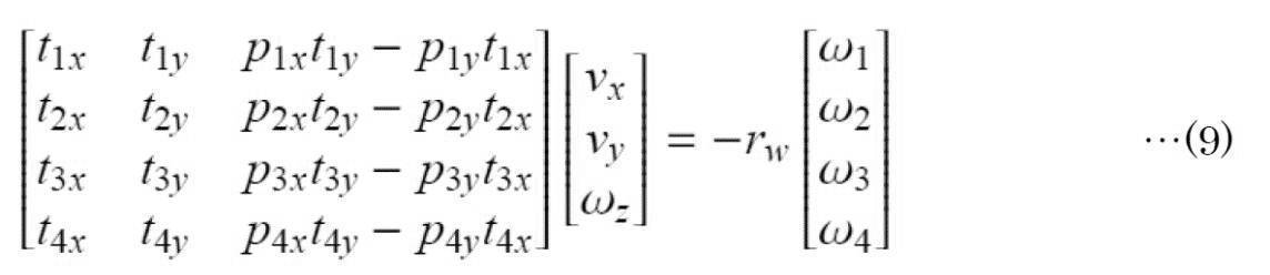
特に、位置ベクトルpk と単位ベクトルtk とが直交する場合(位置ベクトルpk と角速度ベクトルωk とが平行な場合)、上記式(9)は下記式(10)により表される。

車台2の一般化速度ベクトル、ホイール23の角速度を纏めたベクトルωw 、速度伝達行列T は、各々、下記式(11)~下記式(13)により定義される。



上記定義により、ホイール23の角速度ωw と車台2の一般化速度ベクトルとの関係は下記式(14)により表される。ここで、一般化速度ベクトルは台車2の一般化座標qc の時間微分である。

上記定義により、ホイール23の角速度ωw と車台2の一般化速度ベクトルとの関係は下記式(14)により表される。ここで、一般化速度ベクトルは台車2の一般化座標qc の時間微分である。
上記式(14)は一般化速度ベクトルの優決定系であり、一般化速度ベクトルの最小二乗解は速度伝達行列T の一般化逆行列を用いて、下記式(15)により与えられる。

TT は速度伝達行列T の転置行列を表す。ホイール23の配置が適切であれば、TTT の逆行列が存在する。
TT は速度伝達行列T の転置行列を表す。ホイール23の配置が適切であれば、TTT の逆行列が存在する。
仮想仕事の原理に基づいて、ホイール23のトルクを纏めたベクトルτw と車台2の下記式(16)により表される一般化力ベクトルとは下記式(17)の関係を満たす。


ここで、単位ベクトルfx は車台2のXc軸方向の推進力、fy は車台2のYc 軸方向の推進力、τz は車台2のZc 軸周りの旋回トルクである。
ここで、単位ベクトルfx は車台2のXc軸方向の推進力、fy は車台2のYc 軸方向の推進力、τz は車台2のZc 軸周りの旋回トルクである。
上記式(17)はベクトルτw の劣決定系であり、ベクトルτw の最小ノルム解はTT の一般化逆行列を用いて、下記式(18)により与えられる。

例えば、図7(B)に示されるように、車台2の中心2Cから各ホイール23までの距離p がすべて等しい場合、かつ、各ホイール23が互いに90度に等間隔に配列された場合、上記式(13)に記述された速度伝達行列T のそれぞれの行列成分は下記式(19)に示される値となる。

この値を上記式(13)に代入すると、下記式(20)に示される通り、速度伝達行列T を算出することができる。

この値を上記式(13)に代入すると、下記式(20)に示される通り、速度伝達行列T を算出することができる。
(2)全方向移動装置1の車体3の運動学
全方向移動装置1において、車体3の車両前後方向の軸はXb 軸、車体3の車両幅方向の軸はYb 軸、車体3の上下方向の軸はZb 軸と定義される。
車体3は、X0 軸-Y0 軸水平面内を移動(走行)する全方向移動装置1の車台2に自在継手5を介して連結されている。自在継手5により、車体3は、車台2に対して、Y 軸(第1軸方向y )周り及びX軸(第2軸方向x )周りに自由に回転して傾く構成とされている。また、車体3は、車台2の旋回に追従して、Z 軸周りに旋回する構成とされている。
全方向移動装置1において、車体3の車両前後方向の軸はXb 軸、車体3の車両幅方向の軸はYb 軸、車体3の上下方向の軸はZb 軸と定義される。
車体3は、X0 軸-Y0 軸水平面内を移動(走行)する全方向移動装置1の車台2に自在継手5を介して連結されている。自在継手5により、車体3は、車台2に対して、Y 軸(第1軸方向y )周り及びX軸(第2軸方向x )周りに自由に回転して傾く構成とされている。また、車体3は、車台2の旋回に追従して、Z 軸周りに旋回する構成とされている。
車体3の姿勢行列Rb は、これらの3軸に関する姿勢角を使って、下記式(21)により表される。

Rot(A, θ )はA 軸周りに角度θ だけ回転させるときの回転変換行列を表している。ここで、α 、β 、γ はそれぞれヨー角、ピッチ角、ロール角である。
Rot(A, θ )はA 軸周りに角度θ だけ回転させるときの回転変換行列を表している。ここで、α 、β 、γ はそれぞれヨー角、ピッチ角、ロール角である。
図7(A)に示される車体3の重心3Gは、車体3に固定された座標系では下記式(22)に示される定数ベクトルである。この定数ベクトルは基準座標系では下記式(23)により表される。


車体3の角速度ωb はX 軸周り、Y 軸周り及びZ 軸周りの回転に起因するので、下記式(24)に示す通り、角速度ωb を計算することができる。

車体3の旋回は、車台2の旋回と等しく、下記式(25)により表される。

車体3の旋回は、車台2の旋回と等しく、下記式(25)により表される。
車体3の速度vb は下記式(26)により与えられる。

(3)全方向移動装置1の動力学
1.運動方程式の導出
全方向移動装置1において、車台2の質量はmc、車台2のZ 軸周りの慣性モーメントはJczと定義される。車台2の運動エネルギは、車台2の並進運動の運動エネルギと回転運動の運動エネルギとの和であり、下記式(27)により表される。

1.運動方程式の導出
全方向移動装置1において、車台2の質量はmc、車台2のZ 軸周りの慣性モーメントはJczと定義される。車台2の運動エネルギは、車台2の並進運動の運動エネルギと回転運動の運動エネルギとの和であり、下記式(27)により表される。
一方、車体3の質量はmb と定義される。車体3に固定された座標系において、車体3の重心3G周りの慣性テンソルは、定数行列となり、下記式(28)により表される。

車体3の運動エネルギは、車体3の並進運動の運動エネルギと回転運動の運動エネルギとの和であり、下記式(29)により表される。

車体3のポテンシャルエネルギは下記式(30)により与えられる。ここで、g は重力加速度ベクトルである。

下記式(31)に示される全方向移動装置1全体のラグランジュアン(Lagrangian)を用いて、全方向移動装置1の運動方程式は下記式(32)により与えられる。

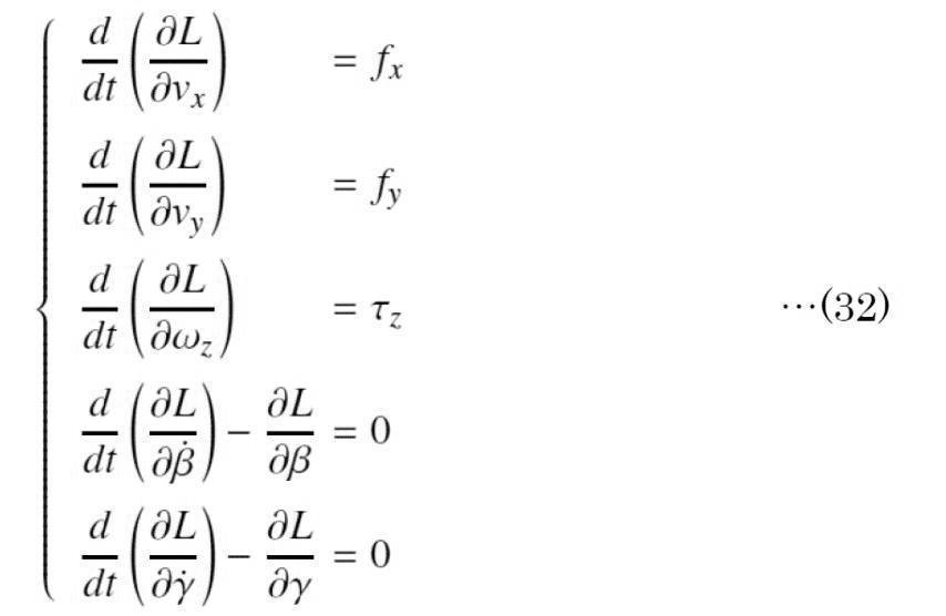
ここで、fx は車台2の車両前後方向の推進力、fy は車台2の車両前後方向の推進力、τz は車台2の旋回トルクである。
ここで、fx は車台2の車両前後方向の推進力、fy は車台2の車両前後方向の推進力、τz は車台2の旋回トルクである。
基準座標系において、車台2の自在継手5の水平方向の位置座標を(x,y) と定義する。
下記式(33)に示される全方向移動装置1の一般化座標を選ぶと、上記式(32)に示される運動方程式は下記式(34)により表される。

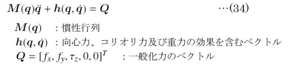
下記式(33)に示される全方向移動装置1の一般化座標を選ぶと、上記式(32)に示される運動方程式は下記式(34)により表される。
2.線形近似モデル
下記式(35)に示される車体3の平衡状態の近傍において、上記式(34)に示される運動方程式の線形近似モデルは下記式(36)により表される。

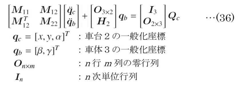
下記式(35)に示される車体3の平衡状態の近傍において、上記式(34)に示される運動方程式の線形近似モデルは下記式(36)により表される。
上記式(36)に示される運動方程式に含まれる部分行列は、下記式(37)~式(40)に示される通りである。



上記式(36)に示される線形近似モデルの入力は車台2の一般化力Qc である。車台2の一般化加速度を新たな入力(一般化目標加速度)u として上記式(36)を書き換えると、線形近似モデルは下記式(41)により表される。
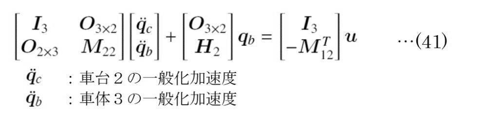
一般化力Qc と新たな入力u とは下記式(42)に示す関係を満たしている。

一般化力Qc と新たな入力u とは下記式(42)に示す関係を満たしている。
上記式(41)に示される新たな線形近似モデルを用いて全方向移動装置1の移動を制御するには、下記式(43)に示される全方向移動装置1の状態量に基づいて、線形近似モデルを安定化させる新たな入力u が求められる。

この新たな入力u に基づいて、上記式(42)により車台2が発生する一般化力Qc が演算される。この演算結果に基づき、ホイール23が発生するトルクが上記式(18)により演算されて求められる。
この新たな入力u に基づいて、上記式(42)により車台2が発生する一般化力Qc が演算される。この演算結果に基づき、ホイール23が発生するトルクが上記式(18)により演算されて求められる。
(4)全方向移動装置1の制御方法
1.車体の安定化
全方向移動装置1では、車体3が車台2に自在継手5を用いて連結されているので、走行時に車体3の姿勢を安定に維持する車台2の適切な運動が必要とされる。このため、本実施の形態では、全方向移動装置1に姿勢安定システム4が組み込まれている。
車台2の適切な運動を求めるため、下記式(44)に示される車体3の状態量の部分空間を状態量として、上記式(41)に示される線形近似モデルのサブシステムが作成される。

このサブシステムは下記式(45)により表される。

上記式(45)に示されるサブシステムを安定化する入力u、すなわち車台2の一般加速度が算出される。
1.車体の安定化
全方向移動装置1では、車体3が車台2に自在継手5を用いて連結されているので、走行時に車体3の姿勢を安定に維持する車台2の適切な運動が必要とされる。このため、本実施の形態では、全方向移動装置1に姿勢安定システム4が組み込まれている。
車台2の適切な運動を求めるため、下記式(44)に示される車体3の状態量の部分空間を状態量として、上記式(41)に示される線形近似モデルのサブシステムが作成される。
このサブシステムは下記式(45)により表される。
上記式(45)に示されるサブシステムを安定化する入力u、すなわち車台2の一般加速度が算出される。
サブシステム中の行列は下記式(46)により表される。ここで、On はn 次正方零行列を意味する。

上記式(45)に示されるサブシステムに対して、一例として半正定の重み行列Qd により決まる二次形式評価規範を最小化する静的な安定化フィードバック制御を用いると、走行時の車体3の姿勢を安定に保つことができる。
ここで、二次形式評価規範は下記式(47)により示される。また、静的な安定化フィードバック制御は下記式(48)により表される。


ここで、二次形式評価規範は下記式(47)により示される。また、静的な安定化フィードバック制御は下記式(48)により表される。
2.摩擦や外乱が駆動系に及ぼす影響の低減
全方向へ移動可能なホイール23を駆動する際には、駆動ユニット22の減速機24に内在する摩擦や慣性モーメントを補償する必要がある。さらに、外乱による影響を低減する必要がある。
全方向へ移動可能なホイール23を駆動する際には、駆動ユニット22の減速機24に内在する摩擦や慣性モーメントを補償する必要がある。さらに、外乱による影響を低減する必要がある。
このため、上記式(48)により決定される入力u を車台2の一般化目標加速度とし、この一般化目標加速度に車台2の一般化座標のフィードバック制御、ここではPID 制御(Proportional Integral Differential Controller)を加えた新たな操作量が使用される。
この新たな操作量(一般化操作加速度)は下記式(49)により表される。
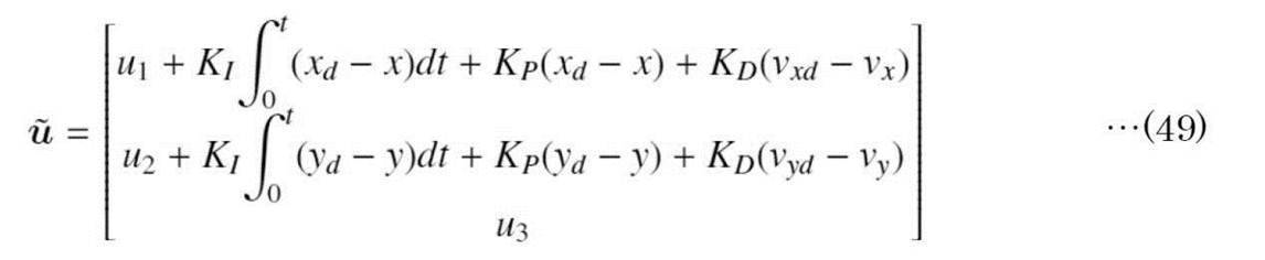
ここで、KI、KP、KDはPID 制御のゲインである。
この新たな操作量(一般化操作加速度)は下記式(49)により表される。
ここで、KI、KP、KDはPID 制御のゲインである。
上記式(49)のu1 、u2、u3 のそれぞれは入力u の第1成分、第2成分、第3成分である。vxd、xd、vyd 、yd、x 、y のそれぞれの目標値は下記式(50)により求められる。
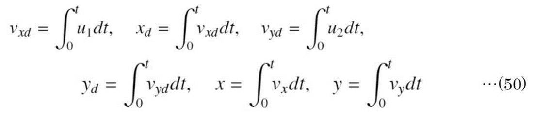
上記式(49)に示される操作量から、車台2が発生すべき一般化力は上記式(42)と同様に下記式(51)により演算される。

各ホイール23が発生すべきトルクは、上記式(18)に基づいて、下記式(52)により演算される。

図4(A)、図4(B)及び図4(D)に示される駆動ユニット22のモータ26の回転軸(図示省略の回転子)と、減速機24の歯車(図示省略)及び減速回転軸241と、ホイール23とを含めた慣性モーメントの減速機24の出力側における値はJw と定義する。また、粘性摩擦係数はFv、慣性摩擦トルクはFc、減速機24の減速比はir と定義する。k 番目のホイール23を駆動するモータ26が出力すべきトルクは下記式(53)により算出される。

ここで、τwk はτw のk 番目の成分である。また、sgn(・)は符号関数である。
上記式(53)において、k 番目の成分であるk 番目のホイール23の角加速度は下記式(54)により算出される。

ここで、τwk はτw のk 番目の成分である。また、sgn(・)は符号関数である。
上記式(53)において、k 番目の成分であるk 番目のホイール23の角加速度は下記式(54)により算出される。
3.全方向移動装置1の制御手順
全方向移動装置1の制御手順は図9に示される通りである。図6及び図8を適宜参酌して、以下に制御手順について詳しく説明する。
全方向移動装置1の制御手順は図9に示される通りである。図6及び図8を適宜参酌して、以下に制御手順について詳しく説明する。
まず、図6及び図8に示される全方向移動装置1の姿勢安定システム4において、姿勢角度検出部42を用いて、車体3の姿勢角及び車体3の角速度が検出される。ここで、各記号、記号名並びに記号の定義は下記表(1)に示される通りである。
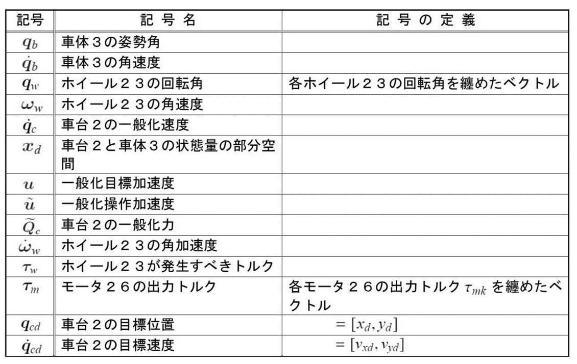
姿勢安定システム4の演算処理部43において、車体3の姿勢角及び角速度が取得される(図9に示されるステップS1。以下、単に「S1」と記載する。)。
姿勢安定システム4の演算処理部43において、車体3の姿勢角及び角速度が取得される(図9に示されるステップS1。以下、単に「S1」と記載する。)。
図4(A)、図4(B)、図4(D)及び図6に示される駆動ユニット22のモータ26に設けられたパルスカウンタ45を用いて、すべてのホイール23の回転角(モータ26の回転角)が検出される。この検出された回転角は角速度情報として演算処理部43へ送られ、演算処理部43は角速度情報を取得する。演算処理部43では、角速度情報に基づいてホイール23の角速度が演算される(S2)。
演算処理部43において、速度伝達行列T の一般化逆行列とホイール23の角速度の情報に基づいて、上記式(15)により車台2の一般化速度が演算される(S3)。
演算処理部43において、速度伝達行列T の一般化逆行列とホイール23の角速度の情報に基づいて、上記式(15)により車台2の一般化速度が演算される(S3)。
演算処理部43において、取得された車体3の姿勢角及び車体3の角速度の情報と、演算により取得された一般化速度の情報とに基づき、上記式(44)により車体3の状態量の部分空間を構成する。演算処理部43では、この部分空間を用いて、静的な安定化フィードバック制御の上記式(48)により、一般化目標加速度が演算される(S4)。
演算された一般化目標加速度の情報と、一般化速度の情報とに基づき、演算処理部43では、上記式(50)によりvxd 、xd、vyd 、yd、x 、y の各目標値が演算される。この各目標値の情報と、一般化目標加速度の情報とに基づき、演算処理部43では上記式(49)により車台2の一般化操作加速度が演算される(S5)。
演算された一般化目標加速度の情報と、取得された車体3の姿勢角の情報とに基づいて、演算処理部43では、上記式(51)により車台2が発生すべき一般化力が演算される(S6)。引き続き、演算された一般化力の情報を用いて、演算処理部43では、上記式(52)によりホイール23が発生すべき出力トルクが演算される(S7)。
演算された一般化操作加速度の情報に基づき、演算処理部43では、上記式(54)によりホイール23の角加速度が演算される。このホイール23の角加速度の情報と、ホイール23が発生すべき出力トルクの情報と、ホイール23の角速度の情報とに基づき、演算処理部43では、上記式(53)によりモータ26の出力トルクが演算される(S8)。
演算処理部43は、演算により得られた出力トルクをトルク指令情報として、図6に示されるデジタルアナログ変換器44へ送る。デジタルアナログ変換器44では、トルク指令情報がデジタル情報からアナログ情報へ変換され、この変換されたトルク指令情報がサーボアンプ28へ送られる。
サーボアンプ28は、モータ26を駆動制御し、ホイール23を回転駆動させて出力トルクを発生させる。
サーボアンプ28は、モータ26を駆動制御し、ホイール23を回転駆動させて出力トルクを発生させる。
なお、図5(A)に示されるロック装置7のロック作動部73が作動されると、ロック装置7により車体3の姿勢がロックされ、かつ、演算処理部43はサーボアンプ28へホイール23の回転を停止させる制御を行う。
(本実施の形態の作用及び効果)
本実施の形態に係る全方向移動装置1は、図1及び図2に示されるように、車台2と、車台2上に配設された車体3とを備えている。車台2にはホイール23が配設され、ホイール23は全方向へ移動可能とされる。
本実施の形態に係る全方向移動装置1は、図1及び図2に示されるように、車台2と、車台2上に配設された車体3とを備えている。車台2にはホイール23が配設され、ホイール23は全方向へ移動可能とされる。
ここで、全方向移動装置1は、図2(B)、図2(C)及び図3に示される自在継手5及び特に図6に示される姿勢安定システム4を備え、更に特に図1~図4に示される車台2には複数のホイール23が配設される。自在継手5は、車台2と車体3とを連結し、車台2に対して車体3の姿勢が変化可能とされる。
ホイール23が複数配設されると、これらのホイール23のすべてが走行路に接地される。このため、車台2の姿勢は走行路の路面の傾斜に合わせて変化する。これに対して、車体3は自在継手5を介して車台2に連結されるので、車体3の姿勢は車台2の姿勢に連動しない。つまり、車体3は、単に自在継手5を介して車台2に連結されているので、車台2に対して静力学的に不安定である。
姿勢安定システム4は、車体3の姿勢が変化した方向へ車台2を移動させ、かつ、車体3の姿勢を安定に維持する。つまり、姿勢安定システム4を備えるので、車台2が移動すると車体3の姿勢が安定に維持され、車体3は動力学的に安定化される。
そして、複数配設されたホイール23と走行路との接地箇所が複数箇所とされるので、ホイール23と走行路との接地面積が増加され、移動時にホイール23は十分なグリップ力を得られる。十分なグリップ力が得られるので、走行路の粉塵や液体がたとえホイール23表面に付着したとしても、走行路に対するホイール23の滑りが小さくなる。
さらに、複数のホイール23が走行路に接地するので、単一の球体が走行路に接地する場合に比べると、段差や不整地の移動時に車台2及び車体3に伝わる振動が小さくなる。
ホイール23が複数配設されると、これらのホイール23のすべてが走行路に接地される。このため、車台2の姿勢は走行路の路面の傾斜に合わせて変化する。これに対して、車体3は自在継手5を介して車台2に連結されるので、車体3の姿勢は車台2の姿勢に連動しない。つまり、車体3は、単に自在継手5を介して車台2に連結されているので、車台2に対して静力学的に不安定である。
姿勢安定システム4は、車体3の姿勢が変化した方向へ車台2を移動させ、かつ、車体3の姿勢を安定に維持する。つまり、姿勢安定システム4を備えるので、車台2が移動すると車体3の姿勢が安定に維持され、車体3は動力学的に安定化される。
そして、複数配設されたホイール23と走行路との接地箇所が複数箇所とされるので、ホイール23と走行路との接地面積が増加され、移動時にホイール23は十分なグリップ力を得られる。十分なグリップ力が得られるので、走行路の粉塵や液体がたとえホイール23表面に付着したとしても、走行路に対するホイール23の滑りが小さくなる。
さらに、複数のホイール23が走行路に接地するので、単一の球体が走行路に接地する場合に比べると、段差や不整地の移動時に車台2及び車体3に伝わる振動が小さくなる。
従って、本実施の形態に係る全方向移動装置1では、静力学的に不安定な車体3を動力学的に安定化し、しかも推進力を向上させ、かつ、静粛性を改善することができる。
また、本実施の形態に係る全方向移動装置1では、図2及び図3に示されるように、自在継手5の対偶が2とされるので、車体3は車台2に対して2つの方向に自由度があり、この2つの方向において車体3の姿勢を変化させることができる。
例えば、仮に三次元座標のY 軸方向(第1軸方向y )を第1回転軸51として第1回転軸51周りに回動する自由度と、X 軸方向(第2軸方向x )を第2回転軸52として第2回転軸52周りに回動する自由度との2つの自由度が設定される。この2つの自由度の範囲において車体3の姿勢を変化させることができる。ここで、Z 軸方向を第3回転軸とする軸周りに回動する自由度は設定されない。このため、車台2を旋回させたときに、車台2の旋回に追従させて車体3を旋回させることができる。つまり、車体3の空回りを無くすことができる。
例えば、仮に三次元座標のY 軸方向(第1軸方向y )を第1回転軸51として第1回転軸51周りに回動する自由度と、X 軸方向(第2軸方向x )を第2回転軸52として第2回転軸52周りに回動する自由度との2つの自由度が設定される。この2つの自由度の範囲において車体3の姿勢を変化させることができる。ここで、Z 軸方向を第3回転軸とする軸周りに回動する自由度は設定されない。このため、車台2を旋回させたときに、車台2の旋回に追従させて車体3を旋回させることができる。つまり、車体3の空回りを無くすことができる。
さらに、本実施の形態に係る全方向移動装置1では、特に図3に示されるように、自在継手5は第1回転軸51、第2回転軸52及び継手部55を備える。第1回転軸51は、車台2上部に支持され、車台2の移動方向の1つを第1軸方向y とする。第2回転軸52は、車体3下部に支持され、車台2の移動方向の他の1つであって第1軸方向y に直交する方向を第2軸方向x とする。継手部55は、第1軸方向y を中心として回転可能とされ、かつ、第2軸方向x を中心として回転可能とされる。
このため、第1軸方向y 及び第2軸方向x の2つの回転軸を中心として継手部55が回転可能とされるので、対偶が2の自在継手5を簡単に実現することができる。
このため、第1軸方向y 及び第2軸方向x の2つの回転軸を中心として継手部55が回転可能とされるので、対偶が2の自在継手5を簡単に実現することができる。
また、本実施の形態に係る全方向移動装置1では、特に図6に示されるように、姿勢安定システム4は駆動ユニット22を備える。駆動ユニット22は、モータ26と、減速機24(例えば図4参照)と、サーボアンプ28とを含んで構成される。図4に示されるように、モータ26は車台2に設けられる。減速機24は、図4に示されるように車台2に設けられ、モータ26の回転駆動力を減速してホイール23に伝達する。サーボアンプ28は、図1及び図2に示されるように車体3に設けられ、図6に示されるようにモータ26に連結されてモータ26を駆動する。
これらを含んで構成される駆動ユニット22を備えるので、姿勢安定システム4では、車台2が移動すると車体3の姿勢が安定に維持され、車体3を動力学的に安定化させることができる。
これらを含んで構成される駆動ユニット22を備えるので、姿勢安定システム4では、車台2が移動すると車体3の姿勢が安定に維持され、車体3を動力学的に安定化させることができる。
さらに、本実施の形態に係る全方向移動装置1では、特に図4(D)に示されるように、ホイール23は第1オムニホイール231及び第2オムニホイール232とされる。第1オムニホイール231は、図4(C)及び図4(D)に示されるように、駆動車輪231Aの円周上に、円周方向を回転軸b方向としてフリーに回転するローラ231Bを複数配設して構成される。同様に、第2オムニホイール232は、駆動車輪232Aの円周上に、円周方向を回転軸b方向としてフリーに回転するローラ232Bを複数配設して構成される。
このため、ホイール23を用いて、駆動車輪231A及び駆動車輪232Aの回転による移動方向に加えて、ローラ231B及びローラ232Bの回転による移動方向へ車台2を移動させることができるので、平面上のすべての方向へ移動可能な全方向移動装置1を実現することができる。
このため、ホイール23を用いて、駆動車輪231A及び駆動車輪232Aの回転による移動方向に加えて、ローラ231B及びローラ232Bの回転による移動方向へ車台2を移動させることができるので、平面上のすべての方向へ移動可能な全方向移動装置1を実現することができる。
また、本実施の形態に係る全方向移動装置1では、図6に示されるように、姿勢安定システム4は、パルスカウンタ45と、姿勢角度検出部42と、演算処理部43とを有する制御ユニット40を備える。制御ユニット40のパルスカウンタ45はモータ26の回転角を取得する。姿勢角度検出部42は、車体3の姿勢角及び車体3の角速度を取得する。演算処理部43は、取得された回転角、姿勢角及び角速度に基づいて、姿勢を安定に維持する車体3の運動状態を演算する。さらに、演算処理部43では、演算結果に基づいてサーボアンプ28が制御される。
このため、姿勢安定システム4では、車台2が移動すると車体3の姿勢が安定に維持され、車体3を動力学的に安定化させることができる。
このため、姿勢安定システム4では、車台2が移動すると車体3の姿勢が安定に維持され、車体3を動力学的に安定化させることができる。
さらに、本実施の形態に係る全方向移動装置1では、特に図3及び図4に示されるように、緩衝装置27が設けられる。緩衝装置27はホイール23と車台2との間に設けられる。このため、走行路を移動中に走行路の路面状態に応じてホイール23に発生する振動は緩衝装置27により減少され、ホイール23から車台2及び車体3に伝わる振動を小さくすることができる。
また、本実施の形態に係る全方向移動装置1では、特に図5(A)及び図5(B)に示されるように、ロック装置7が第1回転軸51及び第2回転軸52に装着される。このロック装置7は、車台2の移動の際に車体3の姿勢を変化可能とし、車台2の移動を停止する際に車体3の姿勢をロックする。また、ロック装置7は車台2の停止状態においても車体3の姿勢をロックする。
このため、車台2の移動を停止したときでも、車体3の姿勢が安定に保持されるので、全方向移動装置1の乗降時や緊急時における搭乗者の安全性を向上させることができる。
このため、車台2の移動を停止したときでも、車体3の姿勢が安定に保持されるので、全方向移動装置1の乗降時や緊急時における搭乗者の安全性を向上させることができる。
さらに、本実施の形態に係る全方向移動装置1の姿勢制御方法は、まず全方向移動装置1の姿勢安定システム4を使用し、姿勢安定システムに図9に示される以下のステップを実行させる。モータ26の回転角が取得され(S2)、車体3の姿勢角及び車体3の角速度が取得される(S1)。次に、これらの取得された回転角、姿勢角及び角速度に基づいて、姿勢安定システム4(図6参照)では姿勢を安定に維持する車体3の運動状態が演算される。演算結果に基づいて、姿勢安定システム4は、サーボアンプ28を制御して車体3の姿勢を安定に維持させた状態において、車台2を移動させる。このため、姿勢制御方法では、全方向移動装置1の車体3を動力学的に安定化させて、車台2を移動させることができる。
(第2実施の形態)
以下、図10~図14を用いて、本発明の第2実施の形態に係る全方向移動装置及びその姿勢制御方法を説明する。
なお、本実施の形態において、第1実施の形態に係る全方向移動装置及びその制御方法の構成と同一又は実質的に同一の構成は同一符号を付し、重複するので、構成の説明は省略する。
以下、図10~図14を用いて、本発明の第2実施の形態に係る全方向移動装置及びその姿勢制御方法を説明する。
なお、本実施の形態において、第1実施の形態に係る全方向移動装置及びその制御方法の構成と同一又は実質的に同一の構成は同一符号を付し、重複するので、構成の説明は省略する。
[全方向移動装置の構成]
図10及び図11(A)~図11(C)に示されるように、本実施の形態に係る全方向移動装置1は、全方向へ移動可能な車台6と、車台6上に配設された車体3と、車台6を移動させ、かつ、車体3の姿勢を安定に維持する姿勢安定システム4とを備えている。さらに、全方向移動装置1は車台6と車体3とを連結する自在継手5を含んで構成されている。
図10及び図11(A)~図11(C)に示されるように、本実施の形態に係る全方向移動装置1は、全方向へ移動可能な車台6と、車台6上に配設された車体3と、車台6を移動させ、かつ、車体3の姿勢を安定に維持する姿勢安定システム4とを備えている。さらに、全方向移動装置1は車台6と車体3とを連結する自在継手5を含んで構成されている。
(1)車台6の構成
図10及び図11(A)~図11(C)、特に図12(A)~図12(D)に示されるように、車台6は車台本体61を備えている。この車台本体61は、天板部611と、左右一対の側板部612及び側板部613とを含んで構成されている。
天板部611は、車両上下方向を厚さ方向とする板材を用いて形成され、平面視において車両幅方向を長手方向とする矩形状に形成されている。ここで、図示を省略しているが、天板部611に対向して天板部611から車体下方側に離間された位置には底板部が配設されている。この底板部は天板部611と同一の形状に形成されている。
側板部612は車両前方側から見て天板部611の車両幅方向右端部に配置され、この右端部に側板部612の上端部が接続されている。側板部612は、車両幅方向を厚さ方向とする板状に形成され、側面視において車両前後方向を長手方向とする矩形状に形成されている。
一方、側板部613は車両前方側から見て天板部611の車両幅方向左端部に配置され、この左端部に側板部613の上端部が接続されている。側板部613は、側板部612と同様に、板状、かつ、矩形状に形成されている。
側板部612の下端部は図示を省略した底板部の右端部に接続され、側板部613の下端部は底板部の左端部に接続されている。従って、車台本体61は、車両前方側から見て中空の矩形枠体として構成されている。また、車台本体61は、第1実施の形態に係る全方向移動装置1の車台本体21と同様に、金属材料又は樹脂材料により形成されている。
図10及び図11(A)~図11(C)、特に図12(A)~図12(D)に示されるように、車台6は車台本体61を備えている。この車台本体61は、天板部611と、左右一対の側板部612及び側板部613とを含んで構成されている。
天板部611は、車両上下方向を厚さ方向とする板材を用いて形成され、平面視において車両幅方向を長手方向とする矩形状に形成されている。ここで、図示を省略しているが、天板部611に対向して天板部611から車体下方側に離間された位置には底板部が配設されている。この底板部は天板部611と同一の形状に形成されている。
側板部612は車両前方側から見て天板部611の車両幅方向右端部に配置され、この右端部に側板部612の上端部が接続されている。側板部612は、車両幅方向を厚さ方向とする板状に形成され、側面視において車両前後方向を長手方向とする矩形状に形成されている。
一方、側板部613は車両前方側から見て天板部611の車両幅方向左端部に配置され、この左端部に側板部613の上端部が接続されている。側板部613は、側板部612と同様に、板状、かつ、矩形状に形成されている。
側板部612の下端部は図示を省略した底板部の右端部に接続され、側板部613の下端部は底板部の左端部に接続されている。従って、車台本体61は、車両前方側から見て中空の矩形枠体として構成されている。また、車台本体61は、第1実施の形態に係る全方向移動装置1の車台本体21と同様に、金属材料又は樹脂材料により形成されている。
車台本体61には姿勢安定システム4を構築する駆動ユニット62が配設されている。詳しく説明すると、車両前方側から見て、車台本体61の車両幅方向右側、かつ、車両前方側に駆動ユニット62の1つの駆動ユニット62Aが配設されている。また、車台本体61の車両幅方向右側、かつ、車両後方側に駆動ユニット62Bが配設されている。同様に、車台本体62の車両幅方向左側、かつ、車両前方側に駆動ユニット62Cが配設され、車台本体62の車両幅方向左側、かつ、車両後方側に駆動ユニット62Dが配設されている。
すなわち、駆動ユニット62は合計4個の駆動ユニット62A~駆動ユニット62Dを備えている。第1実施の形態に係る全方向移動装置1の駆動ユニット22と同様に、駆動ユニット62は、2個以上を備えることを基本構成としているが、本実施の形態では3個以上を備え、走行路に対する車台6の静力学的な安定性が確保されている。
すなわち、駆動ユニット62は合計4個の駆動ユニット62A~駆動ユニット62Dを備えている。第1実施の形態に係る全方向移動装置1の駆動ユニット22と同様に、駆動ユニット62は、2個以上を備えることを基本構成としているが、本実施の形態では3個以上を備え、走行路に対する車台6の静力学的な安定性が確保されている。
特に図13(A)~図13(D)に示されるように、駆動ユニット62の駆動ユニット62Aは、駆動ユニット筐体621を備え、モータ26と、減速機64と、図10及び図11に示されるサーボアンプ28と、を含んで構成されている。
駆動ユニット筐体621は、底壁621Aと、天壁621Bと、左右一対に配置された側壁621C及び側壁621Dとを有し、前面が開放された無前箱状に形成されている。底壁621Aは、車台本体62から車両前方側へ突出され、車両上下方向を板厚方向とする矩形板状に形成されている。天壁621Bは、底壁621Aの車体上方にこの底壁621Aと対向して配置されている。天壁621Bの車両前端部は、底壁621Aよりも車両前方側へ突出されると共に、円弧を描いて車体下方側へ折り曲げられている。
側壁621Cは、底壁621Aの車両幅方向外側端部と天壁621Bの車両幅方向外側端部とにわたって配設され、車両幅方向を厚さ方向とする板状に形成されている。側壁621Cは、水平方向から車両前端部を車体下方側へ向けて屈曲させて、側面視において逆V字形状或いは逆L字形状に形成されている。側壁621Dは、底壁621Aの車両幅方向内側端部と天壁621Bの車両幅方向内側端部とにわたって、側壁621Cに対向して配設され、側壁621Cと同様に板状に形成されている。側壁621C及び側壁621Dの車両前端部はホイール63を回転自在に支持する構成とされている。
駆動ユニット筐体621は、底壁621Aと、天壁621Bと、左右一対に配置された側壁621C及び側壁621Dとを有し、前面が開放された無前箱状に形成されている。底壁621Aは、車台本体62から車両前方側へ突出され、車両上下方向を板厚方向とする矩形板状に形成されている。天壁621Bは、底壁621Aの車体上方にこの底壁621Aと対向して配置されている。天壁621Bの車両前端部は、底壁621Aよりも車両前方側へ突出されると共に、円弧を描いて車体下方側へ折り曲げられている。
側壁621Cは、底壁621Aの車両幅方向外側端部と天壁621Bの車両幅方向外側端部とにわたって配設され、車両幅方向を厚さ方向とする板状に形成されている。側壁621Cは、水平方向から車両前端部を車体下方側へ向けて屈曲させて、側面視において逆V字形状或いは逆L字形状に形成されている。側壁621Dは、底壁621Aの車両幅方向内側端部と天壁621Bの車両幅方向内側端部とにわたって、側壁621Cに対向して配設され、側壁621Cと同様に板状に形成されている。側壁621C及び側壁621Dの車両前端部はホイール63を回転自在に支持する構成とされている。
モータ26は、第1実施の形態に係る全方向移動装置1の電動モータと同様の電動モータであり、駆動ユニット筐体621の側壁621Dに装着されている。このモータ26の図示を省略した駆動回転軸は、駆動ユニット筐体621内部に配設された図示を省略した減速機64の減速回転軸641の一端(図示省略)に連結されている。減速回転軸641の他端は、駆動ユニット筐体621の側壁621Cの車両前方側端部に、回転軸c(図13(A)、図13(B)及び図13(D)参照)を中心として回転自在に支持されている。
減速回転軸641には全方向へ車台6を移動可能なホイール63が配設されている。本実施の形態では、第1実施の形態に係る全方向移動装置1のホイール23、すなわち第1オムニホイール231及び第2オムニホイール232に代えて、特に図13に示されるように、ホイール63にメカナムホイールが使用されている。
特に図13(A)~図13(D)に示されるように、メカナムホイールは、減速回転軸641に固定された歯車状の駆動車輪63Aの円周上に、駆動車輪63Aの回転軸cに対して傾斜する方向を軸方向dとしてフリーに回転する樽状のローラ63Bを複数配設して構成されている。回転軸dは回転軸cに対してねじれの位置において例えば絶対値で135度の傾きαに設定されている(図14(B)参照)。ローラ63Bは、駆動車輪63Aの円周上に、等間隔の配列ピッチにおいて、ここでは12個配列されている。
図12(A)、図12(D)及び図13(A)~図13(D)示されるように、駆動ユニット62Aは緩衝装置67を介して車台本体61に配設されている。具体的には、緩衝装置67は、駆動ユニット筐体621の車両後方側内部に配設され、車台本体61の側板部612の車両前端部に装着されている。第1実施の形態に係る全方向移動装置1の緩衝装置27と同様に、緩衝装置67は、走行路からホイール63を介して車台6に伝達される振動を減衰させて小さくする。
そして、図12(A)~図12(D)に示される駆動ユニット62の駆動ユニット62Bは、Y 軸を中心として、駆動ユニット62Aに対して左右対称の形状とされ、駆動ユニット62Aと基本構造を同一構造としている。駆動ユニット62Cは、X 軸を中心として、駆動ユニット62Aに対して左右対称の形状とされ、駆動ユニット62Aと基本構造を同一構造としている。そして、駆動ユニット62Dは、Y 軸を中心として、駆動ユニット62Cに対して左右対称の形状とされ、又はX 軸を中心として、駆動ユニット62Bに対して左右対称の形状とされ、駆動ユニット62Aと基本構造を同一構造としている。
(2)車体3の構成
図10及び図11(A)~図11(C)に戻って、車体3は、車体本体31と、ハンドル32と、足置き部33と、サドル37と、を含んで構成されている。車体本体31は車台2上に配設されている。本実施の形態では、車体本体31は、車両前後方向を軸方向として延設された中空管状部材を主体に構成されている。
図10及び図11(A)~図11(C)に戻って、車体3は、車体本体31と、ハンドル32と、足置き部33と、サドル37と、を含んで構成されている。車体本体31は車台2上に配設されている。本実施の形態では、車体本体31は、車両前後方向を軸方向として延設された中空管状部材を主体に構成されている。
車体本体31の車両前端部には一体に形成されて上方に立設されたハンドルサポート321が配設され、ハンドルサポート321の上端部にハンドル32が装着されている。ハンドル32は車両幅方向外側へ向かって左右にそれぞれ突出された棒状に形成され、搭乗者はハンドル32に捕まって全方向移動装置1を走行させる。本実施の形態でも、ハンドル32は、垂直軸(Z 軸)周りに旋回しない固定式とされている。
始動スイッチ、ブレーキ、保安部品等は、第1実施の形態に係る全方向移動装置1と同様にハンドル32に装着可能とされている。
始動スイッチ、ブレーキ、保安部品等は、第1実施の形態に係る全方向移動装置1と同様にハンドル32に装着可能とされている。
足置き部33は、車体本体31の車両前端部において、車体本体31から垂下された前後一対のサポート331に支持されている。足置き部33は、車両幅方向外側に左右一対に配設され、車両前後方向及び車両幅方向に広がる平坦部位を備え、搭乗者の右足及び左足を載せる部位として使用されている。
また、車体本体31の車両前後方向中間部には車体上方側へ立設されたサドルサポート371を介してサドル37が装着されている。サドル37には搭乗者が着座可能とされ、搭乗者がサドル37に着座状態において、全方向移動装置1を走行させることができる。
また、車体本体31の車両前後方向中間部には車体上方側へ立設されたサドルサポート371を介してサドル37が装着されている。サドル37には搭乗者が着座可能とされ、搭乗者がサドル37に着座状態において、全方向移動装置1を走行させることができる。
車体本体31の車両後方端部には、箱状の車体カバー36が取付けられている。車体カバー36の内部には、前述の図6に示される姿勢安定システム4が収納されている。また、車体カバー36の内部には、駆動ユニット62を構築するサーボアンプ28、電源46等が収納されている。
(3)自在継手5の構成
第1実施の形態に係る全方向移動装置1の自在継手5と同様に、図10、図11(B)、図11(C)及び図12(A)~図12(D)に示されるように、車台6と車体3とを連結する自在継手5が配設されている。図5(A)及び図5(B)に詳細に示されるように、自在継手5は、第1回転軸51と、第2回転軸52と、スパイダ55とを含んで構成されている。
第1実施の形態に係る全方向移動装置1の自在継手5と同様に、図10、図11(B)、図11(C)及び図12(A)~図12(D)に示されるように、車台6と車体3とを連結する自在継手5が配設されている。図5(A)及び図5(B)に詳細に示されるように、自在継手5は、第1回転軸51と、第2回転軸52と、スパイダ55とを含んで構成されている。
第1回転軸51は、車両幅方向を第1軸方向y として構成され、車体本体31の車両前後方向の中間下部に第1軸方向y に沿って互いに離間されて一対に設けられている。この一対の第1回転軸51は、第1軸方向y において互いに離間された一対の第1支持部53を介して車体本体31の車両前後方向中間部に支持されている。
第2回転軸52は、車両前後方向を第2軸方向x として構成され、ここでは車台6の天板部611の車台前後方向中間部及び車台幅方向中間部に第2軸方向x に沿って互いに離間されて一対に設けられている。本実施の形態では、第2軸方向x は第1軸方向y と同一平面上に設定されている。この一対の第2回転軸52は、第2回転軸x において互いに離間された一対の第2支持部54を介して天板部611の車台前後方向中間部に支持されている。
第2回転軸52は、車両前後方向を第2軸方向x として構成され、ここでは車台6の天板部611の車台前後方向中間部及び車台幅方向中間部に第2軸方向x に沿って互いに離間されて一対に設けられている。本実施の形態では、第2軸方向x は第1軸方向y と同一平面上に設定されている。この一対の第2回転軸52は、第2回転軸x において互いに離間された一対の第2支持部54を介して天板部611の車台前後方向中間部に支持されている。
スパイダ55の構成、第1回転軸51の構成、第1支持部53の構成、第2回転軸52の構成、第2支持部54の構成は、いずれも、第1実施の形態に係る全方向移動装置1の自在継手5の各部位の構成と同一とされている。
これにより、自在継手5は、第1回転軸51を中心として車台6に対して車体3を回転可能とし、かつ、第2回転軸52を中心として車台6に対して車体3を回転可能としている。つまり、自在継手5の対偶は2に設定されている。
これにより、自在継手5は、第1回転軸51を中心として車台6に対して車体3を回転可能とし、かつ、第2回転軸52を中心として車台6に対して車体3を回転可能としている。つまり、自在継手5の対偶は2に設定されている。
(4)ロック装置7の構成
図10~図12における図示を省略するが、ロック装置7は、前述の図5(A)及び図5(B)に示される第1実施の形態に係る全方向移動装置1のロック装置7の構成と同一の構成とされている。つまり、ロック装置7は、自在継手5の第1回転軸51に装着された第1ロック装置71と、第2回転軸52に装着された第2ロック装置72と、第1ロック装置71及び第2ロック装置72を作動させるロック作動部73とを含んで構成されている。詳細な説明は、重複するので、省略する。
図10~図12における図示を省略するが、ロック装置7は、前述の図5(A)及び図5(B)に示される第1実施の形態に係る全方向移動装置1のロック装置7の構成と同一の構成とされている。つまり、ロック装置7は、自在継手5の第1回転軸51に装着された第1ロック装置71と、第2回転軸52に装着された第2ロック装置72と、第1ロック装置71及び第2ロック装置72を作動させるロック作動部73とを含んで構成されている。詳細な説明は、重複するので、省略する。
(5)姿勢安定システムの構成
姿勢安定システム4は、図10~図13に示される駆動ユニット62と、前述の図6に示される制御ユニット40とを含んで構成されている。制御ユニット40は、パルスカウンタ45、姿勢角度検出部42、演算処理部43、アナログ変換器44等を備え、第1実施の形態に係る全方向移動装置1の制御ユニット40と同一の構成とされている。このため、姿勢安定システム4の詳細な説明は省略する。
姿勢安定システム4は、図10~図13に示される駆動ユニット62と、前述の図6に示される制御ユニット40とを含んで構成されている。制御ユニット40は、パルスカウンタ45、姿勢角度検出部42、演算処理部43、アナログ変換器44等を備え、第1実施の形態に係る全方向移動装置1の制御ユニット40と同一の構成とされている。このため、姿勢安定システム4の詳細な説明は省略する。
[全方向移動装置の姿勢制御方法]
全方向移動装置1の姿勢制御方法は、基本的には第1実施の形態に係る全方向移動装置1の姿勢制御方法と同様である。ここで、図14(A)は三次元座標系において第2実施の形態に係る全方向移動装置1をモデル化して示す概略斜視図、図14(B)は全方向移動装置1の車台6及びホイール(メカナムホイール)63をモデル化して示す概略平面図である。前述の図6、図8及び図9を用いつつ、適宜、図10~図13を参酌し、姿勢制御方法を説明する。
全方向移動装置1の姿勢制御方法は、基本的には第1実施の形態に係る全方向移動装置1の姿勢制御方法と同様である。ここで、図14(A)は三次元座標系において第2実施の形態に係る全方向移動装置1をモデル化して示す概略斜視図、図14(B)は全方向移動装置1の車台6及びホイール(メカナムホイール)63をモデル化して示す概略平面図である。前述の図6、図8及び図9を用いつつ、適宜、図10~図13を参酌し、姿勢制御方法を説明する。
(1)全方向移動装置1の車台6の運動学
まず最初に、図10~図13に示される全方向移動装置1の車台6及び車体3の運動学を、図14(A)を用いて説明する。ここで、三次元座標はX 軸X0 、Y 軸Y0 、Z 軸Z0 により表されている。
まず最初に、図10~図13に示される全方向移動装置1の車台6及び車体3の運動学を、図14(A)を用いて説明する。ここで、三次元座標はX 軸X0 、Y 軸Y0 、Z 軸Z0 により表されている。
全方向移動装置1において、車台6の車両前後方向の軸はXc 軸、車台6の車両幅方向の軸はYc 軸、自在継手5の中心を通る車台6の上下方向の軸はZc 軸と定義される。
車台6に取り付けられた自在継手5の位置の速度ベクトルvc は、第1実施の形態に係る全方向移動装置1の姿勢制御方法において説明した上記式(1)により表される。
車台6の角速度ベクトルωc は上記式(2)により表される。
車台6の中心6Cを始点とするk 番目のホイール63の中心の位置ベクトルpk は上記式(3)により表される。ここで、本実施の形態では4つの駆動ユニット62A~62Dを備え、4つのホイール63を備えているので、k は1、…、4である。
車台6の角速度ベクトルωc は上記式(2)により表される。
車台6の中心6Cを始点とするk 番目のホイール63の中心の位置ベクトルpk は上記式(3)により表される。ここで、本実施の形態では4つの駆動ユニット62A~62Dを備え、4つのホイール63を備えているので、k は1、…、4である。
k 番目のホイール63の角速度ベクトルをωk とし、角速度ベクトルωk は角速度ベクトルωk の大きさ(|ωk|)とされる。
角速度ベクトルωk を下記式(55)に記述される同じ向きの単位ベクトルとすると、角速度ベクトルωk は下記(56)により表される。


ホイール63の中心を始点とするホイール63の接地点の位置ベクトルは上記式(4)により表される。rw はホイール63の半径である。
角速度ベクトルωk を下記式(55)に記述される同じ向きの単位ベクトルとすると、角速度ベクトルωk は下記(56)により表される。
ホイール63の中心を始点とするホイール63の接地点の位置ベクトルは上記式(4)により表される。rw はホイール63の半径である。
k 番目のホイール63の接地点を始点とするローラ63Bの回転軸と平行な単位ベクトル(メカナムホイールの接線ベクトル)tk は上記式(5)により表される。
上記定義により、k 番目のホイール63の接地点の速度vk は上記式(6)により表される。
上記定義により、k 番目のホイール63の接地点の速度vk は上記式(6)により表される。
k 番目のホイール63のローラ63Bが接地点において接地し、ローラ63Bが軸方向に滑らないと仮定すると、速度vk と単位ベクトルtk との間に上記式(7)の関係が成立する。
上記式(6)を上記式(7)に代入し、速度vk、位置ベクトルpk 、角速度ベクトルωk及び単位ベクトルtk がZ 軸Z0 と直交し、角速度ベクトルωc 及び半径rwがZ 軸Z0 に平行であることを考慮すると、下記式(57)が得られる。

上記式(6)を上記式(7)に代入し、速度vk、位置ベクトルpk 、角速度ベクトルωk及び単位ベクトルtk がZ 軸Z0 と直交し、角速度ベクトルωc 及び半径rwがZ 軸Z0 に平行であることを考慮すると、下記式(57)が得られる。
上記式(57)を纏めて表記すると、下記式(58)が得られる。
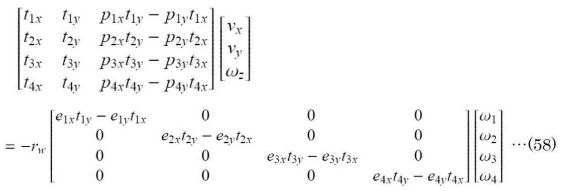
車台6の一般化速度ベクトルは上記式(11)、ホイール63の角速度を纏めたベクトルωw は上記式(12)のそれぞれにより定義され、速度伝達行列T は下記式(59)により定義される。

上記定義により、ホイール63の角速度ωw と車台6の一般化速度ベクトルとの関係は上記式(14)により表すことができる。ここで、上記式(59)において、記号[ ]-1は逆行列を表す。
上記定義により、ホイール63の角速度ωw と車台6の一般化速度ベクトルとの関係は上記式(14)により表すことができる。ここで、上記式(59)において、記号[ ]-1は逆行列を表す。
上記式(14)は一般化速度ベクトルの優決定系であり、一般化速度ベクトルの最小二乗解は速度伝達行列T の一般化逆行列を用いて、上記式(15)により与えられる。
ホイール63の配置が適切あれば、TTT の逆行列が存在する。
ホイール63の配置が適切あれば、TTT の逆行列が存在する。
仮想仕事の原理に基づいて、ホイール63のトルクを纏めたベクトルτw と車台6の上記式(16)により表される一般化力ベクトルとは上記式(17)の関係を満たす。
ここで、上記式(16)において、単位ベクトルfx は車台6のXc 軸方向の推進力、fy は車台6のYc 軸方向の推進力、τz は車台6のZc 軸周りの旋回トルクである。
ここで、上記式(16)において、単位ベクトルfx は車台6のXc 軸方向の推進力、fy は車台6のYc 軸方向の推進力、τz は車台6のZc 軸周りの旋回トルクである。
上記式(17)はベクトルτw の劣決定系であり、ベクトルτw の最小ノルム解はTT の一般化逆行列を用いて、上記式(18)により与えられる。
例えば、図14(B)に示されるように、全方向移動装置1の車台6のホイールベース(wheelbase)をlw 、トレッド(axle track)をlt とすると、上記式(59)の行列成分のそれぞれの値が下記式(60)~下記式(62)に示す通りとなる。



例えば、図14(B)に示されるように、全方向移動装置1の車台6のホイールベース(wheelbase)をlw 、トレッド(axle track)をlt とすると、上記式(59)の行列成分のそれぞれの値が下記式(60)~下記式(62)に示す通りとなる。
この値を上記式(59)に代入すると、下記式(63)に示される通り、速度伝達行列T を算出することができる。

(2)全方向移動装置1の車体3の運動学
本実施の形態に係る全方向移動装置1の車体3の運動学の説明は、第1実施の形態に係る全方向移動装置1の車体3の運動学の説明と同一である。但し、第1実施の形態において「車台2」は、本実施の形態において「車台6」と読み替える。
本実施の形態に係る全方向移動装置1の車体3の運動学の説明は、第1実施の形態に係る全方向移動装置1の車体3の運動学の説明と同一である。但し、第1実施の形態において「車台2」は、本実施の形態において「車台6」と読み替える。
(3)全方向移動装置1の動力学
本実施の形態に係る全方向移動装置1の動力学の説明は、「1.運動方程式の導出」、「2.線形近似モデル」のそれぞれの説明を含み、第1実施の形態に係る全方向移動装置1の動力学の説明と同一である。但し、第1実施の形態において「車台2」は、本実施の形態において「車台6」と読み替える。
本実施の形態に係る全方向移動装置1の動力学の説明は、「1.運動方程式の導出」、「2.線形近似モデル」のそれぞれの説明を含み、第1実施の形態に係る全方向移動装置1の動力学の説明と同一である。但し、第1実施の形態において「車台2」は、本実施の形態において「車台6」と読み替える。
(4)全方向移動装置1の制御方法
本実施の形態に係る全方向移動装置1の制御方法の説明は、「1.車体の安定化」、「2.摩擦や外乱が駆動系に及ぼす影響の低減」、「3.全方向移動装置1の制御手順」のそれぞれの説明を含み、第1実施の形態に係る全方向移動装置1の制御方法の説明と同一である。同様に、第1実施の形態において「車台2」は、本実施の形態において「車台6」と読み替える。
本実施の形態に係る全方向移動装置1の制御方法の説明は、「1.車体の安定化」、「2.摩擦や外乱が駆動系に及ぼす影響の低減」、「3.全方向移動装置1の制御手順」のそれぞれの説明を含み、第1実施の形態に係る全方向移動装置1の制御方法の説明と同一である。同様に、第1実施の形態において「車台2」は、本実施の形態において「車台6」と読み替える。
(本実施の形態の作用及び効果)
本実施の形態に係る全方向移動装置1及びその姿勢制御方法では、第1実施の形態に係る全方向移動装置1及びその姿勢制御方法により得られる作用効果と同様に、静力学的に不安定な車体3を動力学的に安定化し、しかも推進力を向上させ、かつ、静粛性を改善することができるという作用効果が得られる。
本実施の形態に係る全方向移動装置1及びその姿勢制御方法では、第1実施の形態に係る全方向移動装置1及びその姿勢制御方法により得られる作用効果と同様に、静力学的に不安定な車体3を動力学的に安定化し、しかも推進力を向上させ、かつ、静粛性を改善することができるという作用効果が得られる。
また、本実施の形態に係る全方向移動装置1では、特に図13(A)~図13(D)に示されるように、ホイール63はメカナムホイールとされる。メカナムホイールは、図13(A)~図13(C)に示されるように、駆動車輪63Aの円周上に、駆動車輪63Aの回転軸cに対して傾斜する方向を軸方向dとしてフリーに回転する樽状のローラ63Bを複数配設して構成されている。
このため、ホイール63を用いて、駆動車輪63A及び駆動車輪63Aの回転による移動方向に加えて、ローラ63Bの回転による移動方向へ車台6を移動させることができるので、平面上のすべての方向へ移動可能な全方向移動装置1を実現することができる。
このため、ホイール63を用いて、駆動車輪63A及び駆動車輪63Aの回転による移動方向に加えて、ローラ63Bの回転による移動方向へ車台6を移動させることができるので、平面上のすべての方向へ移動可能な全方向移動装置1を実現することができる。
(その他の実施の形態)
本発明は、上記実施の形態に限定されるものではなく、その要旨を逸脱しない範囲において、種々変形可能である。
例えば、本発明では、オムニホイールの走行路への接地点の速度を与える上記式(6)がメカナムホイールの走行路への接地点の速度を与える式と同一であることから、オムニホイールとメカナムホイールとを混在させた全方向移動装置を構築することができる。すなわち、本発明は、第1実施の形態に係る全方向移動装置と第2実施の形態に係る全方向移動装置とを組み合わせた全方向移動装置を構築可能である。
本発明は、上記実施の形態に限定されるものではなく、その要旨を逸脱しない範囲において、種々変形可能である。
例えば、本発明では、オムニホイールの走行路への接地点の速度を与える上記式(6)がメカナムホイールの走行路への接地点の速度を与える式と同一であることから、オムニホイールとメカナムホイールとを混在させた全方向移動装置を構築することができる。すなわち、本発明は、第1実施の形態に係る全方向移動装置と第2実施の形態に係る全方向移動装置とを組み合わせた全方向移動装置を構築可能である。
また、本発明は、第1実施の形態に係る全方向移動装置において、車体にサドル等の座席を装着し、搭乗者が着座状態において走行可能とするようにしてもよい。逆に、本発明は、第2実施の形態に係る全方向移動装置において、車体からサドルを取外し、搭乗者が立ち状態において走行するようにしてもよい。
2017年5月26日に出願された日本国特許出願2017-104669号の開示は、その全体が参照により本明細書に取り込まれる。
Claims (9)
- 全方向へ移動可能なホイールが複数配設された車台と、
当該車台上に配設された車体と、
前記車台と前記車体とを連結し、前記車台に対して前記車体の姿勢が変化可能とされる自在継手と、
前記車体の姿勢が変化した方向へ前記車台を移動させ、かつ、前記車体の姿勢を安定に維持する姿勢安定システムと、
を備えた全方向移動装置。 - 前記自在継手の対偶が2である請求項1に記載の全方向移動装置。
- 前記自在継手は、
前記車台上部に支持され、前記車台の移動方向の1つを第1軸方向とする第1回転軸と、
前記車体下部に支持され、前記車台の移動方向の他の1つであって前記第1軸方向に交差する方向を第2軸方向とする第2回転軸と、
前記第1回転軸を中心として回転可能とされ、かつ、前記第2回転軸を中心として回転可能とされるスパイダと、
を含んで構成されている請求項2に記載の全方向移動装置。 - 前記姿勢安定システムは、
前記車台に設けられたモータと、
前記車台に設けられ、前記モータの回転駆動力を減速して前記ホイールに伝達する減速機と、
前記車体に設けられ、前記モータに連結されて前記モータを駆動するサーボアンプと、
を有する駆動ユニットを備えている請求項1~請求項3のいずれか1項に記載の全方向移動装置。 - 前記ホイールは、オムニホイール及びメカナムホイールの少なくとも一方である請求項1~請求項4のいずれか1項に記載の全方向移動装置。
- 前記姿勢安定システムは、
前記モータの回転角を取得する角度検出部と、
前記車体の姿勢角及び前記車体の角速度を取得する姿勢角度検出部と、
前記角度検出部により取得された前記回転角と、前記姿勢角度検出部により取得された前記姿勢角及び前記角速度とに基づいて、姿勢を安定に維持する前記車体の運動状態を演算し、この演算結果に基づいて前記サーボアンプを制御する演算処理部と、
を有する制御ユニットを備えている請求項4に記載の全方向移動装置。 - 前記ホイールと前記車台との間に、前記ホイールから前記車台に伝達される振動を減少させる緩衝装置を更に備えている請求項1~請求項6のいずれか1項に記載の全方向移動装置。
- 前記車台の移動の際に前記車体の姿勢を変化可能とし、前記車台の移動を停止する際に前記車体の姿勢をロックするロック装置が、前記第1回転軸及び前記第2回転軸に装着されている請求項3に記載の全方向移動装置。
- 請求項6に記載された前記全方向移動装置の前記姿勢安定システムを備え、当該姿勢安定システムに、
前記モータの回転角を取得するステップと、
前記車体の姿勢角及び前記車体の角速度を取得するステップと、
前記回転角、前記姿勢角及び前記角速度に基づいて、姿勢を安定に維持する前記車体の運動状態を演算するステップと、
この演算結果に基づいて前記サーボアンプを制御して姿勢を安定に維持させた状態において前記車台を移動させるステップと、
を実行させる全方向移動装置の姿勢制御方法。
Priority Applications (3)
| Application Number | Priority Date | Filing Date | Title |
|---|---|---|---|
| US16/617,029 US11157020B2 (en) | 2017-05-26 | 2018-05-14 | Omnidirectional moving device and attitude control method for the same |
| JP2019519579A JP7229537B2 (ja) | 2017-05-26 | 2018-05-14 | 全方向移動装置及びその姿勢制御方法 |
| CN201880034669.9A CN110709316B (zh) | 2017-05-26 | 2018-05-14 | 全向移动装置及其姿态控制方法 |
Applications Claiming Priority (2)
| Application Number | Priority Date | Filing Date | Title |
|---|---|---|---|
| JP2017-104669 | 2017-05-26 | ||
| JP2017104669 | 2017-05-26 |
Publications (1)
| Publication Number | Publication Date |
|---|---|
| WO2018216530A1 true WO2018216530A1 (ja) | 2018-11-29 |
Family
ID=64395496
Family Applications (1)
| Application Number | Title | Priority Date | Filing Date |
|---|---|---|---|
| PCT/JP2018/018611 Ceased WO2018216530A1 (ja) | 2017-05-26 | 2018-05-14 | 全方向移動装置及びその姿勢制御方法 |
Country Status (4)
| Country | Link |
|---|---|
| US (1) | US11157020B2 (ja) |
| JP (1) | JP7229537B2 (ja) |
| CN (1) | CN110709316B (ja) |
| WO (1) | WO2018216530A1 (ja) |
Cited By (3)
| Publication number | Priority date | Publication date | Assignee | Title |
|---|---|---|---|---|
| CN111409737A (zh) * | 2020-03-27 | 2020-07-14 | 吉林大学 | 一种无转向系可全向移动的电动运载平台及其控制方法 |
| CN111506054A (zh) * | 2019-01-31 | 2020-08-07 | 上海制驰智能科技有限公司 | 一种4wid-4wis机器人底盘的自动导引方法 |
| JP2023115819A (ja) * | 2022-02-08 | 2023-08-21 | 株式会社ダイヘン | 移動体、及び制御装置 |
Families Citing this family (3)
| Publication number | Priority date | Publication date | Assignee | Title |
|---|---|---|---|---|
| JP6910547B2 (ja) * | 2018-05-16 | 2021-07-28 | 三菱電機株式会社 | 移動台車 |
| JP7347381B2 (ja) * | 2020-09-11 | 2023-09-20 | トヨタ自動車株式会社 | 立ち乗り式車両 |
| CN114719672B (zh) * | 2022-05-26 | 2023-06-20 | 西安航空学院 | 带麦克纳姆轮的多功能单兵模拟作战平台 |
Citations (6)
| Publication number | Priority date | Publication date | Assignee | Title |
|---|---|---|---|---|
| DE19820059A1 (de) * | 1998-05-06 | 1999-11-18 | Werner Bernhard | Einrad zur Beförderung einer Last und Verfahren zu dessen Lage-Regelung |
| JP2010076630A (ja) * | 2008-09-26 | 2010-04-08 | Toshiba Corp | 移動台車 |
| JP2010167807A (ja) * | 2009-01-20 | 2010-08-05 | Toyota Motor Corp | 走行装置及びその制御方法 |
| JP2015047961A (ja) * | 2013-09-02 | 2015-03-16 | 株式会社ジェイテクト | 車両 |
| JP2016198494A (ja) * | 2015-04-10 | 2016-12-01 | オージーオー・テクノロジー・リミテッドOgo Technology Limited | 複数の旋回軸を有する傾斜機構を備えた動力付き移動装置 |
| JP2017052417A (ja) * | 2015-09-10 | 2017-03-16 | 株式会社土佐電子 | 複合メカナムホイールおよび搬送台車 |
Family Cites Families (22)
| Publication number | Priority date | Publication date | Assignee | Title |
|---|---|---|---|---|
| US4237990A (en) * | 1979-01-02 | 1980-12-09 | Hau T | Omnidirectional vehicle |
| JP3070015B2 (ja) * | 1990-11-30 | 2000-07-24 | 本田技研工業株式会社 | 不安定車両の走行制御装置 |
| JP4448759B2 (ja) * | 2004-11-09 | 2010-04-14 | 本田技研工業株式会社 | 自走台車の走行制御方法 |
| JP2006282160A (ja) | 2005-03-07 | 2006-10-19 | Univ Of Tokyo | 全方向移動ロボット及び該ロボットの全方向移動駆動機構 |
| US8285474B2 (en) * | 2006-06-29 | 2012-10-09 | Kabushikikaisha Equos Research | Vehicle |
| JP2008230548A (ja) * | 2007-03-23 | 2008-10-02 | Toyota Motor Corp | 倒立振子型移動体、及びその制御方法 |
| JP4605204B2 (ja) * | 2007-10-24 | 2011-01-05 | トヨタ自動車株式会社 | 倒立振子型移動体、及びその制御方法 |
| JP2009234524A (ja) | 2008-03-28 | 2009-10-15 | Sony Corp | 搬送装置と駆動機構 |
| JP5337408B2 (ja) * | 2008-05-28 | 2013-11-06 | 村田機械株式会社 | 自律移動体及びその移動制御方法 |
| CN102149596B (zh) * | 2008-09-11 | 2013-06-05 | 丰田自动车株式会社 | 移动体及其控制方法 |
| JP5270307B2 (ja) * | 2008-11-12 | 2013-08-21 | トヨタ自動車株式会社 | 移動体 |
| WO2012008005A1 (ja) * | 2010-07-12 | 2012-01-19 | 有限会社ティーエム | 倒立振子型移動体および移動ロボット |
| US8833232B1 (en) * | 2011-11-30 | 2014-09-16 | Drs Sustainment Systems, Inc. | Operational control logic for harmonized turret with gimbaled sub-systems |
| AU2015249084B2 (en) | 2012-02-09 | 2017-09-07 | Omeo Group Limited | Powered Mobility Device with Tilt Mechanism Having Multiple Pivots |
| JP6081271B2 (ja) * | 2013-03-29 | 2017-02-15 | 本田技研工業株式会社 | 倒立振子型車両 |
| AT14540U1 (de) * | 2013-06-13 | 2016-01-15 | Amst Systemtechnik Gmbh | Hochdynamischer selbstfahrender Fahrsimulator sowie Verfahren zur Simulation eines Übergangs von einem unbeschleunigten in einen beschleunigten Zustand |
| US9864396B1 (en) * | 2014-08-05 | 2018-01-09 | Hydro-Gear Limited Partnership | Highly maneuverable mowing vehicle with Mecanum wheels |
| US9999557B2 (en) * | 2016-07-14 | 2018-06-19 | Challenging Solutions, Inc. | Robotic mobility device |
| CN106394715A (zh) * | 2016-12-02 | 2017-02-15 | 河海大学常州校区 | 一种全向移动轮式机器人平台及控制方法 |
| CN107089128B (zh) * | 2017-05-19 | 2023-08-04 | 深圳市优必选科技有限公司 | 机器人行走装置和轮式机器人 |
| CN108883799A (zh) * | 2017-06-30 | 2018-11-23 | 深圳市大疆创新科技有限公司 | 四轮底盘车、两轮底盘车、总成及控制方法 |
| US11052003B2 (en) * | 2017-12-05 | 2021-07-06 | Avanchair S.R.L. | Wheelchair with integrated transfer device |
-
2018
- 2018-05-14 WO PCT/JP2018/018611 patent/WO2018216530A1/ja not_active Ceased
- 2018-05-14 CN CN201880034669.9A patent/CN110709316B/zh active Active
- 2018-05-14 US US16/617,029 patent/US11157020B2/en active Active
- 2018-05-14 JP JP2019519579A patent/JP7229537B2/ja active Active
Patent Citations (6)
| Publication number | Priority date | Publication date | Assignee | Title |
|---|---|---|---|---|
| DE19820059A1 (de) * | 1998-05-06 | 1999-11-18 | Werner Bernhard | Einrad zur Beförderung einer Last und Verfahren zu dessen Lage-Regelung |
| JP2010076630A (ja) * | 2008-09-26 | 2010-04-08 | Toshiba Corp | 移動台車 |
| JP2010167807A (ja) * | 2009-01-20 | 2010-08-05 | Toyota Motor Corp | 走行装置及びその制御方法 |
| JP2015047961A (ja) * | 2013-09-02 | 2015-03-16 | 株式会社ジェイテクト | 車両 |
| JP2016198494A (ja) * | 2015-04-10 | 2016-12-01 | オージーオー・テクノロジー・リミテッドOgo Technology Limited | 複数の旋回軸を有する傾斜機構を備えた動力付き移動装置 |
| JP2017052417A (ja) * | 2015-09-10 | 2017-03-16 | 株式会社土佐電子 | 複合メカナムホイールおよび搬送台車 |
Cited By (5)
| Publication number | Priority date | Publication date | Assignee | Title |
|---|---|---|---|---|
| CN111506054A (zh) * | 2019-01-31 | 2020-08-07 | 上海制驰智能科技有限公司 | 一种4wid-4wis机器人底盘的自动导引方法 |
| CN111506054B (zh) * | 2019-01-31 | 2024-11-01 | 上海制驰智能科技有限公司 | 一种4wid-4wis机器人底盘的自动导引方法 |
| CN111409737A (zh) * | 2020-03-27 | 2020-07-14 | 吉林大学 | 一种无转向系可全向移动的电动运载平台及其控制方法 |
| JP2023115819A (ja) * | 2022-02-08 | 2023-08-21 | 株式会社ダイヘン | 移動体、及び制御装置 |
| JP7792093B2 (ja) | 2022-02-08 | 2025-12-25 | 株式会社ダイヘン | 移動体、及び制御装置 |
Also Published As
| Publication number | Publication date |
|---|---|
| CN110709316A (zh) | 2020-01-17 |
| CN110709316B (zh) | 2021-09-07 |
| JP7229537B2 (ja) | 2023-02-28 |
| US11157020B2 (en) | 2021-10-26 |
| US20210132633A1 (en) | 2021-05-06 |
| JPWO2018216530A1 (ja) | 2020-07-09 |
Similar Documents
| Publication | Publication Date | Title |
|---|---|---|
| JP7229537B2 (ja) | 全方向移動装置及びその姿勢制御方法 | |
| US20200317018A1 (en) | Vehicle and methods for improving stability and occupant comfort | |
| EP1529556B1 (en) | Travelling apparatus and method for controlling thereof | |
| US10894571B2 (en) | Leaning vehicle | |
| US5975225A (en) | Transportation vehicles with stability enhancement using CG modification | |
| US8322471B2 (en) | Angular momentum torque enhancement for spherical vehicles | |
| JP6381813B2 (ja) | バランス一輪車 | |
| US20210394575A1 (en) | Vehicle and methods for improving stability and occupant comfort | |
| CN101568465A (zh) | 倒立双轮式搬运车及其控制方法 | |
| JP4556418B2 (ja) | 走行装置及びその制御方法 | |
| JP4442319B2 (ja) | 走行装置 | |
| JP4734666B2 (ja) | 3輪型乗用移動台車 | |
| JP2008052362A (ja) | 自律移動装置 | |
| CN206243331U (zh) | 基于麦克纳姆轮设计的全向移动平衡车 | |
| CN106882283A (zh) | 一种机器人系统 | |
| JP2006282160A (ja) | 全方向移動ロボット及び該ロボットの全方向移動駆動機構 | |
| JP3560403B2 (ja) | 全方向移動車両およびその制御方法 | |
| JP3826687B2 (ja) | 全方向移動台車 | |
| JPWO2016035726A1 (ja) | 手押し車 | |
| US12204350B1 (en) | Autonomous robot double drive assembly | |
| JP6951611B2 (ja) | 全方向移動装置及びその姿勢制御方法 | |
| KR101788577B1 (ko) | 볼 로봇을 이용한 탑승형 이동장치의 제어방법 | |
| CN109987184B (zh) | 滑板车 | |
| JP5337650B2 (ja) | 倒立振子型移動体 | |
| KR20170107197A (ko) | 볼 로봇을 이용한 탑승형 이동장치 |
Legal Events
| Date | Code | Title | Description |
|---|---|---|---|
| 121 | Ep: the epo has been informed by wipo that ep was designated in this application |
Ref document number: 18805320 Country of ref document: EP Kind code of ref document: A1 |
|
| ENP | Entry into the national phase |
Ref document number: 2019519579 Country of ref document: JP Kind code of ref document: A |
|
| NENP | Non-entry into the national phase |
Ref country code: DE |
|
| 122 | Ep: pct application non-entry in european phase |
Ref document number: 18805320 Country of ref document: EP Kind code of ref document: A1 |