WO2018207556A1 - 冷媒蒸発器およびその製造方法 - Google Patents
冷媒蒸発器およびその製造方法 Download PDFInfo
- Publication number
- WO2018207556A1 WO2018207556A1 PCT/JP2018/015659 JP2018015659W WO2018207556A1 WO 2018207556 A1 WO2018207556 A1 WO 2018207556A1 JP 2018015659 W JP2018015659 W JP 2018015659W WO 2018207556 A1 WO2018207556 A1 WO 2018207556A1
- Authority
- WO
- WIPO (PCT)
- Prior art keywords
- tubes
- refrigerant
- plate
- tube
- flow
- Prior art date
- Legal status (The legal status is an assumption and is not a legal conclusion. Google has not performed a legal analysis and makes no representation as to the accuracy of the status listed.)
- Ceased
Links
Images


Classifications
-
- F—MECHANICAL ENGINEERING; LIGHTING; HEATING; WEAPONS; BLASTING
- F28—HEAT EXCHANGE IN GENERAL
- F28D—HEAT-EXCHANGE APPARATUS, NOT PROVIDED FOR IN ANOTHER SUBCLASS, IN WHICH THE HEAT-EXCHANGE MEDIA DO NOT COME INTO DIRECT CONTACT
- F28D1/00—Heat-exchange apparatus having stationary conduit assemblies for one heat-exchange medium only, the media being in contact with different sides of the conduit wall, in which the other heat-exchange medium is a large body of fluid, e.g. domestic or motor car radiators
- F28D1/02—Heat-exchange apparatus having stationary conduit assemblies for one heat-exchange medium only, the media being in contact with different sides of the conduit wall, in which the other heat-exchange medium is a large body of fluid, e.g. domestic or motor car radiators with heat-exchange conduits immersed in the body of fluid
- F28D1/04—Heat-exchange apparatus having stationary conduit assemblies for one heat-exchange medium only, the media being in contact with different sides of the conduit wall, in which the other heat-exchange medium is a large body of fluid, e.g. domestic or motor car radiators with heat-exchange conduits immersed in the body of fluid with tubular conduits
- F28D1/053—Heat-exchange apparatus having stationary conduit assemblies for one heat-exchange medium only, the media being in contact with different sides of the conduit wall, in which the other heat-exchange medium is a large body of fluid, e.g. domestic or motor car radiators with heat-exchange conduits immersed in the body of fluid with tubular conduits the conduits being straight
- F28D1/0535—Heat-exchange apparatus having stationary conduit assemblies for one heat-exchange medium only, the media being in contact with different sides of the conduit wall, in which the other heat-exchange medium is a large body of fluid, e.g. domestic or motor car radiators with heat-exchange conduits immersed in the body of fluid with tubular conduits the conduits being straight the conduits having a non-circular cross-section
- F28D1/05366—Assemblies of conduits connected to common headers, e.g. core type radiators
- F28D1/05391—Assemblies of conduits connected to common headers, e.g. core type radiators with multiple rows of conduits or with multi-channel conduits combined with a particular flow pattern, e.g. multi-row multi-stage radiators
-
- F—MECHANICAL ENGINEERING; LIGHTING; HEATING; WEAPONS; BLASTING
- F25—REFRIGERATION OR COOLING; COMBINED HEATING AND REFRIGERATION SYSTEMS; HEAT PUMP SYSTEMS; MANUFACTURE OR STORAGE OF ICE; LIQUEFACTION SOLIDIFICATION OF GASES
- F25B—REFRIGERATION MACHINES, PLANTS OR SYSTEMS; COMBINED HEATING AND REFRIGERATION SYSTEMS; HEAT PUMP SYSTEMS
- F25B5/00—Compression machines, plants or systems, with several evaporator circuits, e.g. for varying refrigerating capacity
- F25B5/04—Compression machines, plants or systems, with several evaporator circuits, e.g. for varying refrigerating capacity arranged in series
-
- F—MECHANICAL ENGINEERING; LIGHTING; HEATING; WEAPONS; BLASTING
- F25—REFRIGERATION OR COOLING; COMBINED HEATING AND REFRIGERATION SYSTEMS; HEAT PUMP SYSTEMS; MANUFACTURE OR STORAGE OF ICE; LIQUEFACTION SOLIDIFICATION OF GASES
- F25B—REFRIGERATION MACHINES, PLANTS OR SYSTEMS; COMBINED HEATING AND REFRIGERATION SYSTEMS; HEAT PUMP SYSTEMS
- F25B39/00—Evaporators; Condensers
- F25B39/02—Evaporators
- F25B39/022—Evaporators with plate-like or laminated elements
- F25B39/024—Evaporators with plate-like or laminated elements with elements constructed in the shape of a hollow panel
-
- F—MECHANICAL ENGINEERING; LIGHTING; HEATING; WEAPONS; BLASTING
- F25—REFRIGERATION OR COOLING; COMBINED HEATING AND REFRIGERATION SYSTEMS; HEAT PUMP SYSTEMS; MANUFACTURE OR STORAGE OF ICE; LIQUEFACTION SOLIDIFICATION OF GASES
- F25B—REFRIGERATION MACHINES, PLANTS OR SYSTEMS; COMBINED HEATING AND REFRIGERATION SYSTEMS; HEAT PUMP SYSTEMS
- F25B39/00—Evaporators; Condensers
- F25B39/02—Evaporators
- F25B39/028—Evaporators having distributing means
-
- F—MECHANICAL ENGINEERING; LIGHTING; HEATING; WEAPONS; BLASTING
- F28—HEAT EXCHANGE IN GENERAL
- F28D—HEAT-EXCHANGE APPARATUS, NOT PROVIDED FOR IN ANOTHER SUBCLASS, IN WHICH THE HEAT-EXCHANGE MEDIA DO NOT COME INTO DIRECT CONTACT
- F28D1/00—Heat-exchange apparatus having stationary conduit assemblies for one heat-exchange medium only, the media being in contact with different sides of the conduit wall, in which the other heat-exchange medium is a large body of fluid, e.g. domestic or motor car radiators
- F28D1/02—Heat-exchange apparatus having stationary conduit assemblies for one heat-exchange medium only, the media being in contact with different sides of the conduit wall, in which the other heat-exchange medium is a large body of fluid, e.g. domestic or motor car radiators with heat-exchange conduits immersed in the body of fluid
- F28D1/04—Heat-exchange apparatus having stationary conduit assemblies for one heat-exchange medium only, the media being in contact with different sides of the conduit wall, in which the other heat-exchange medium is a large body of fluid, e.g. domestic or motor car radiators with heat-exchange conduits immersed in the body of fluid with tubular conduits
- F28D1/0408—Multi-circuit heat exchangers, e.g. integrating different heat exchange sections in the same unit or heat exchangers for more than two fluids
- F28D1/0417—Multi-circuit heat exchangers, e.g. integrating different heat exchange sections in the same unit or heat exchangers for more than two fluids with particular circuits for the same heat exchange medium, e.g. with the heat exchange medium flowing through sections having different heat exchange capacities or for heating/cooling the heat exchange medium at different temperatures
-
- F—MECHANICAL ENGINEERING; LIGHTING; HEATING; WEAPONS; BLASTING
- F28—HEAT EXCHANGE IN GENERAL
- F28F—DETAILS OF HEAT-EXCHANGE AND HEAT-TRANSFER APPARATUS, OF GENERAL APPLICATION
- F28F1/00—Tubular elements; Assemblies of tubular elements
- F28F1/02—Tubular elements of cross-section which is non-circular
- F28F1/022—Tubular elements of cross-section which is non-circular with multiple channels
-
- F—MECHANICAL ENGINEERING; LIGHTING; HEATING; WEAPONS; BLASTING
- F28—HEAT EXCHANGE IN GENERAL
- F28F—DETAILS OF HEAT-EXCHANGE AND HEAT-TRANSFER APPARATUS, OF GENERAL APPLICATION
- F28F1/00—Tubular elements; Assemblies of tubular elements
- F28F1/10—Tubular elements and assemblies thereof with means for increasing heat-transfer area, e.g. with fins, with projections, with recesses
- F28F1/12—Tubular elements and assemblies thereof with means for increasing heat-transfer area, e.g. with fins, with projections, with recesses the means being only outside the tubular element
- F28F1/126—Tubular elements and assemblies thereof with means for increasing heat-transfer area, e.g. with fins, with projections, with recesses the means being only outside the tubular element consisting of zig-zag shaped fins
-
- F—MECHANICAL ENGINEERING; LIGHTING; HEATING; WEAPONS; BLASTING
- F28—HEAT EXCHANGE IN GENERAL
- F28F—DETAILS OF HEAT-EXCHANGE AND HEAT-TRANSFER APPARATUS, OF GENERAL APPLICATION
- F28F17/00—Removing ice or water from heat-exchange apparatus
- F28F17/005—Means for draining condensates from heat exchangers, e.g. from evaporators
-
- F—MECHANICAL ENGINEERING; LIGHTING; HEATING; WEAPONS; BLASTING
- F28—HEAT EXCHANGE IN GENERAL
- F28F—DETAILS OF HEAT-EXCHANGE AND HEAT-TRANSFER APPARATUS, OF GENERAL APPLICATION
- F28F9/00—Casings; Header boxes; Auxiliary supports for elements; Auxiliary members within casings
- F28F9/02—Header boxes; End plates
- F28F9/0202—Header boxes having their inner space divided by partitions
- F28F9/0204—Header boxes having their inner space divided by partitions for elongated header box, e.g. with transversal and longitudinal partitions
- F28F9/0214—Header boxes having their inner space divided by partitions for elongated header box, e.g. with transversal and longitudinal partitions having only longitudinal partitions
- F28F9/0217—Header boxes having their inner space divided by partitions for elongated header box, e.g. with transversal and longitudinal partitions having only longitudinal partitions the partitions being separate elements attached to header boxes
-
- F—MECHANICAL ENGINEERING; LIGHTING; HEATING; WEAPONS; BLASTING
- F28—HEAT EXCHANGE IN GENERAL
- F28D—HEAT-EXCHANGE APPARATUS, NOT PROVIDED FOR IN ANOTHER SUBCLASS, IN WHICH THE HEAT-EXCHANGE MEDIA DO NOT COME INTO DIRECT CONTACT
- F28D21/00—Heat-exchange apparatus not covered by any of the groups F28D1/00 - F28D20/00
- F28D2021/0019—Other heat exchangers for particular applications; Heat exchange systems not otherwise provided for
- F28D2021/008—Other heat exchangers for particular applications; Heat exchange systems not otherwise provided for for vehicles
- F28D2021/0085—Evaporators
-
- F—MECHANICAL ENGINEERING; LIGHTING; HEATING; WEAPONS; BLASTING
- F28—HEAT EXCHANGE IN GENERAL
- F28F—DETAILS OF HEAT-EXCHANGE AND HEAT-TRANSFER APPARATUS, OF GENERAL APPLICATION
- F28F9/00—Casings; Header boxes; Auxiliary supports for elements; Auxiliary members within casings
- F28F9/22—Arrangements for directing heat-exchange media into successive compartments, e.g. arrangements of guide plates
- F28F2009/222—Particular guide plates, baffles or deflectors, e.g. having particular orientation relative to an elongated casing or conduit
- F28F2009/224—Longitudinal partitions
Definitions
- the present disclosure relates to a refrigerant evaporator that cools a fluid to be cooled and a manufacturing method thereof.
- the inside of the intermediate tank section has substantially the same cross-sectional area in the refrigerant flow direction (longitudinal direction of the intermediate tank section), and the refrigerant flow rate changes in the process of collecting refrigerant from the tubes and distributing the refrigerant to the tubes. .
- the static pressure applied to the inner wall surface varies depending on the position in the longitudinal direction in the intermediate tank, and a difference occurs between the pressure applied to the inlet and the pressure applied to the outlet in each tube. For this reason, there is a possibility that refrigerant distribution may deteriorate.
- Patent Document 1 two heat exchange core parts are arranged in series with respect to the air flow direction, and two heat exchanger core parts arranged in a superimposed manner when viewed from the air flow direction.
- a refrigerant evaporator in which tubes are connected by an intermediate flow path is disclosed.
- the intermediate flow path is configured by superposing three plate materials of a first plate material, a second plate material, and a third plate material. Specifically, a tube insertion hole into which an end portion of the tube is inserted is formed in the first plate material. A through hole communicating with the tube insertion hole is formed in the second plate material. The third plate material is formed in a flat plate shape without a through hole. Then, when these three plate materials are overlapped, an intermediate flow path is formed by the through hole of the second plate material.
- the first heat exchange core part and the second heat exchange core part are connected to each set of tubes that are superposed when viewed from the air flow direction. Can do. For this reason, since the intermediate tank unit for collecting and distributing the refrigerant with respect to the plurality of tubes can be eliminated, an increase in pressure loss, deterioration of refrigerant distribution, and the like are unlikely to occur.
- the present disclosure suppresses an increase in pressure loss at the connection part of the two core parts while suppressing an increase in the number of parts, and It aims at suppressing the deterioration of the refrigerant
- the refrigerant evaporator performs heat exchange between the fluid to be cooled and the refrigerant.
- the refrigerant evaporator includes a first evaporator, a second evaporator, a first core, a second core, a first plate, and a second plate.
- the first evaporator is configured so that the fluid to be cooled passes through the inside in the flow direction.
- the second evaporator is configured so that the fluid to be cooled passes through the inside in the flow direction, and is disposed in series with the first evaporator in the flow direction.
- the first core part includes a plurality of first tubes through which the refrigerant flows.
- the plurality of first tubes extend in the tube longitudinal direction perpendicular to the flow direction and are laminated in the tube lamination direction perpendicular to both the flow direction and the tube longitudinal direction.
- the second core part includes a plurality of second tubes through which the refrigerant flows.
- the plurality of second tubes extend in the tube longitudinal direction and are stacked in the tube stacking direction.
- the first plate is connected to one end portion of the first core portion and one end portion of the second core portion on one side of the tube longitudinal direction, and is connected to one end portion of the plurality of first tubes and one end portion of the plurality of second tubes. To accommodate.
- the second plate faces the first core portion and the second core portion across the first plate in the tube longitudinal direction, and is joined to the first plate.
- the second plate has a plurality of ribs extending in the flow direction while projecting away from the first core portion and the second core portion in the tube longitudinal direction.
- the plurality of ribs together with the first plate define a plurality of intermediate flow paths therein.
- the plurality of first tubes and the plurality of second tubes are arranged so as to overlap each other when viewed from the flow direction, and are a set of one first tube and one second tube facing each other in the flow direction.
- a plurality of sets of tubes are formed.
- a plurality of intermediate flow paths communicate a plurality of sets of tubes.
- a plurality of intermediate flow paths respectively connect a plurality of sets of tubes. That is, one first tube of the plurality of first tubes and one second tube of the plurality of second tubes can be connected by one intermediate flow path. For this reason, the intermediate tank part with a large internal volume which distributes or aggregates the refrigerant to the plurality of tubes can be eliminated. Then, in a plurality of intermediate flow paths that are connecting portions of the plurality of first tubes and the plurality of second tubes, a rapid expansion of the refrigerant flow paths formed inside the plurality of first tubes and the plurality of second tubes, respectively.
- FIG. 2 is an exploded perspective view of FIG. 1. It is an expansion perspective view which shows a part of 1st core part and 2nd core part in 1st Embodiment. It is an expansion perspective view which shows the intermediate tank part vicinity in 1st Embodiment. It is an expansion perspective view which shows the 1st plate in 1st Embodiment. It is an expansion perspective view which shows the 2nd plate in 1st Embodiment. It is an expanded sectional view showing the middle tank part neighborhood in a 1st embodiment.
- FIG. 8 is a sectional view taken along line VIII-VIII in FIG.
- the refrigerant evaporator according to the present embodiment is applied to a vapor compression refrigeration cycle of a vehicle air conditioner that adjusts the temperature in the passenger compartment, and absorbs heat from the air (blowing air) blown into the passenger compartment to generate a refrigerant (liquid phase). It is a cooling heat exchanger that cools the air by evaporating the refrigerant.
- air corresponds to “cooled fluid”.
- illustration of the fin 30 mentioned later is abbreviate
- the refrigeration cycle includes a compressor, a radiator (condenser), an expansion valve, and the like (not shown) in addition to the refrigerant evaporator 1, and in this embodiment, liquid is received between the radiator and the expansion valve. It is configured as a receiver cycle in which a device is arranged.
- the refrigerant of the refrigeration cycle is mixed with refrigeration oil for lubricating the compressor, and a part of the refrigeration oil circulates in the cycle together with the refrigerant.
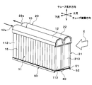
- the refrigerant evaporator 1 of the present embodiment includes a first evaporator 10 and a second evaporator that are arranged in series with respect to the air flow direction (flow direction of the fluid to be cooled) X.
- the unit 20 is provided.
- the first evaporator 10 is disposed on the downstream side (leeward side) in the air flow direction X with respect to the second evaporator 20.
- the basic configuration of the first evaporator 10 and the second evaporator 20 is the same, and includes the heat exchange core parts 11 and 21 and the tank parts 12 and 22 disposed above the heat exchange core parts 11 and 21, respectively. Configured.
- the heat exchange core part in the first evaporator 10 is referred to as a first core part 11, and the heat exchange core part in the second evaporator 20 is referred to as a second core part 21.
- the tank part in the first evaporator 10 is referred to as a first tank part 12, and the tank part in the second evaporator 20 is referred to as a second tank part 22.
- each of the first core portion 11 and the second core portion 21 a plurality of tubes 15 and 25 extending in the vertical direction and fins 30 (see FIG. 3) joined between the adjacent tubes 15 and 25 are alternately stacked. It is comprised by the laminated body arrange
- the stacking direction in the stacked body of the plurality of tubes 15 and 25 and the plurality of fins 30 is referred to as a tube stacking direction.
- a plurality of tubes constituting the first core portion 11 are referred to as a plurality of first tubes 15, and a plurality of tubes constituting the second core portion 21 are referred to as a plurality of second tubes 25.
- the longitudinal direction of each of the plurality of first tubes 15 and the plurality of second tubes 25 is referred to as a tube longitudinal direction.
- the plurality of first tubes 15 since the plurality of first tubes 15 have the same configuration, the plurality of first tubes 15 may be collectively referred to as the first tube 15 in the following description. Further, since the plurality of second tubes 25 have the same configuration, the plurality of second tubes 25 may be collectively referred to as the second tube 25 in the following description.
- a refrigerant passage through which a refrigerant flows is formed in each of the first tube 15 and the second tube 25.
- the first tube 15 and the second tube 25 are each formed of a flat tube having a flat shape with a cross-sectional shape extending along the air flow direction X.
- the first tube 15 and the second tube 25 are arranged so as to overlap each other when viewed from the air flow direction X.
- the first tube 15 and the second tube 25 that is superposed when viewed from the air flow direction X with respect to the first tube 15 are referred to as a pair of tubes 15 and 25.
- the refrigerant evaporator 1 has a plurality of sets of tubes 15 and 25.
- An intermediate flow path 40 that connects the pair of tubes 15 and 25 to each other is provided on one end side in the tube longitudinal direction of the pair of tubes 15 and 25.
- the intermediate flow path 40 is disposed on the lower end side of the pair of tubes 15 and 25.
- a plurality of intermediate flow paths 40 are provided below the first core portion 11 and the second core portion 21.
- the plurality of intermediate flow paths 40 are arranged side by side in the tube stacking direction. The details of the intermediate flow path 40 will be described later.
- the other end side (upper end side) of the first tube 15 in the longitudinal direction of the tube is connected to the first tank portion 12.
- the second tube 25 is connected to the second tank portion 22 at the other end side (upper end side) in the tube longitudinal direction.
- the fin 30 is a corrugated fin formed by bending a thin plate material into a wave shape.
- the fin 30 is joined to the flat outer surface side of the first tube 15 and the second tube 25 and functions as a heat exchange promoting part for expanding the heat transfer area between the air and the refrigerant.
- the fin 30 is joined to both the pair of tubes 15 and 25.
- side plates 113 and 213 that reinforce the core portions 11 and 22 are provided at both ends in the tube stacking direction in the stacked body of the first tube 15, the second tube 25, and the fin 30, respectively. Is arranged.
- the side plates 113 and 213 are joined to the fins 30 arranged on the outermost side in the tube stacking direction.
- the first tank portion 12 is constituted by a cylindrical member in which one end side in the tube stacking direction is closed and a refrigerant introduction portion 12a is formed on the other end side in the tube stacking direction.
- the refrigerant introduction part 12a introduces the low-pressure refrigerant decompressed by an expansion valve (not shown) into the tank of the first tank part 12.
- the first tank portion 12 is closed at the left end when viewed from the upstream side of the air flow, and the refrigerant introduction portion 12a is formed at the right end when viewed from the upstream side of the air flow. ing.
- the first tank portion 12 has a through hole (not shown) in which the tube longitudinal direction other end side (upper end side) of each first tube 15 is inserted and joined to the bottom portion.
- the first tank portion 12 is configured such that its internal space communicates with each first tube 15 of the first core portion 11.
- the first tank unit 12 functions as a refrigerant distribution unit that distributes the refrigerant to the first core unit 11.
- the second tank portion 22 is configured by a cylindrical member having one end side in the tube stacking direction closed and a refrigerant outlet portion 22a formed on the other end side in the tube stacking direction.
- the refrigerant derivation unit 22a derives the refrigerant from the inside of the tank of the second tank unit 22 to the suction side of a compressor (not shown).
- the second tank portion 22 is closed at the left end when viewed from the upstream side of the air flow, and the refrigerant outlet portion 22a is formed at the right end when viewed from the upstream side of the air flow. ing.
- the second tank portion 22 has a through hole (not shown) in which the other end side (upper end side) in the tube longitudinal direction of each second tube 25 is inserted and joined at the bottom.
- the second tank portion 22 is configured such that its internal space communicates with each second tube 25 of the second core portion 21.
- the second tank unit 22 functions as a refrigerant collecting unit that collects the refrigerant from the second core unit 21.
- an intermediate tank portion 50 that is a flow path forming member that forms a plurality of intermediate flow paths 40 at one end side (lower end side) in the tube longitudinal direction of the first core section 11 and the second core section 21.
- the intermediate tank unit 50 is formed by combining the first plate 51 and the second plate 52.
- the first plate 51 is formed in a substantially rectangular plate shape. One end (lower end) of each of the first tube 15 and the second tube 25 in the tube longitudinal direction is joined to the first plate 51. Specifically, the first plate 51 has a first insertion hole 511 into which one end of the first tube 15 in the longitudinal direction of the tube is inserted, and a first insertion end of the second tube 25 in the longitudinal direction of the tube. 2 insertion holes 512 are formed. The first insertion hole 511 and the second insertion hole 512 are each formed by burring the first plate 51.
- the second plate 52 has a substantially U-shaped cross section viewed from the tube stacking direction.
- the second plate 52 includes a flat surface portion 521 and two side surface portions 522.
- the flat portion 521 is formed in a substantially rectangular plate shape and extends in a direction perpendicular to the tube longitudinal direction.
- the side surface portions 522 extend from both end portions of the plane portion 521 in the air flow direction X so as to be separated from the first core portion 11 and the second core portion 21 in the tube longitudinal direction.
- the flat surface portion 521 and the two side surface portions 522 are integrally formed.
- the flat portion 521 is formed with a plurality of ribs 523 that protrude in the longitudinal direction of the tube so as to be separated from the first core portion 11 and the second core portion 21 and extend in the air flow direction X.
- a plurality of concave portions 524 that are recessed so as to be separated from the first plate 51 in the tube longitudinal direction are formed on the surface of the flat portion 521 on the first plate 51 side.
- Each recess 524 communicates with a first insertion hole 511 and a second insertion hole 512 into which a pair of tubes 15 and 25 are inserted.
- the portion of the flat portion 521 where the plurality of ribs 523 are not formed is joined to the first plate 51.
- the plurality of recesses 524 of the second plate 52 define a plurality of intermediate flow paths 40 together with the surface of the first plate 51 that faces the plurality of ribs 523.
- the plurality of intermediate flow paths 40 are configured by the inner surfaces of the plurality of ribs 523 in the second plate 52 and the surface of the first plate 51 that faces the plurality of ribs 523.
- each of the plurality of ribs 523 has a substantially U-shaped cross section viewed from the air flow direction X. More specifically, each of the plurality of ribs 523 has a substantially U-shaped cross section as viewed from the air flow direction X over the entire region in the air flow direction X.
- the plurality of ribs 523 since the plurality of ribs 523 have the same configuration, hereinafter, the plurality of ribs 523 are collectively referred to as ribs 523. Since the plurality of intermediate flow paths 40 have the same configuration, the plurality of intermediate flow paths 40 will be collectively referred to as intermediate flow paths 40 hereinafter.
- the intermediate flow path 40 is configured so that the length in the tube stacking direction is constant. For this reason, the cross-sectional area of the intermediate flow path 40 is determined based on the length of the intermediate flow path 40 in the tube longitudinal direction.
- the intermediate flow path 40 includes an upstream portion 41, a midstream portion 42, and a downstream portion 43.
- the upstream part 41, the midstream part 42, and the downstream part 43 are arranged in this order from the refrigerant flow upstream side.
- the cross-sectional area of the midstream portion 42 is larger than both the cross-sectional area of the upstream portion 41 and the cross-sectional area of the downstream portion 43.
- the upstream portion 41 is configured such that the cross-sectional area gradually increases toward the downstream side of the refrigerant flow.
- the upstream portion 41 is configured such that the cross-sectional area linearly increases toward the refrigerant flow downstream side. Specifically, the length in the tube longitudinal direction of the upstream portion 41 is gradually increased toward the refrigerant flow downstream side.
- the upstream portion 41 is disposed on one end side (lower end side) of the first tube 15 in the longitudinal direction of the tube.
- the upstream portion 41 communicates with the first tube 15. For this reason, the refrigerant that has flowed out of the first tube 15 flows into the upstream portion 41.
- the midstream portion 42 is configured to have a constant cross-sectional area toward the downstream side of the refrigerant flow.
- the midstream portion 42 is disposed at a position corresponding to the gap 60 between the first tube 15 and the second tube 25.
- the midstream portion 42 is connected to the upstream portion 41. For this reason, the refrigerant that has flowed out of the upstream portion 41 flows into the midstream portion 42.
- the downstream portion 43 is configured such that the cross-sectional area gradually decreases toward the downstream side of the refrigerant flow.
- the downstream part 43 is comprised so that a cross-sectional area may reduce linearly toward a refrigerant
- the length in the tube longitudinal direction is gradually shortened toward the downstream side of the refrigerant flow.
- the downstream portion 43 is disposed on one end side (lower end side) of the second tube 25 in the tube longitudinal direction.
- the upstream side of the downstream portion 43 in the refrigerant flow is connected to the midstream portion 42. For this reason, the refrigerant flowing out from the midstream portion 42 flows into the downstream portion 43.
- the downstream side of the refrigerant flow in the downstream portion 43 communicates with the second tube 25. For this reason, the refrigerant that has flowed through the downstream portion 43 flows into the second tube 25.
- the first tube 15 has a first partition member 151 that partitions the first refrigerant flow path formed in the first tube 15 into a plurality of narrow flow paths 150 arranged in the air flow direction X.
- the second tube 25 includes a second partition member 251 that partitions the second coolant channel formed in the second tube 25 into a plurality of narrow channels 250 arranged in the air flow direction X.
- the cross-sectional area of the midstream portion 42 of the intermediate flow path 40 is set to 0.3 to 3.0 times the cross-sectional area of the first tube 15 or the second tube 25.
- the cross-sectional area of the midstream portion 42 of the intermediate flow path 40 is the sum of the cross-sectional areas of the plurality of narrow channels 150 in the first tube 15 or the sum of the cross-sectional areas of the plurality of narrow channels 250 in the second tube 25. It is set from 0.3 times to 3.0 times.
- the most upstream portion in the air flow direction X is referred to as the most upstream portion 44.
- the most downstream portion in the air flow direction X is referred to as the most downstream portion 45.
- the most upstream part 44 and the most downstream part 45 are configured such that the cross-sectional area of the intermediate flow path 40 is the smallest.
- the cross-sectional areas of the most upstream portion 44 and the most downstream portion 45 are set to 0.3 to 3.0 times the cross-sectional areas of the plurality of narrow channels 150 and the plurality of narrow channels 250, respectively. ing.
- the cross-sectional areas of the most upstream part 44 and the most downstream part 45 are each 0.3 times the cross-sectional area of one of the plurality of narrow channels 150 or one of the plurality of narrow channels 250. It is set to 3.0 times.
- the plurality of narrow channels 150 in the first tube 15 are configured by a first narrow channel 1501 to an nth narrow channel 150 n (n is a natural number) arranged in order toward the second tube 25.
- the first narrow channel 1501 is located farthest from the second tube 25, and the nth narrow channel 150 n is located closest to the second tube 25.
- the portion of the intermediate flow path 40 where the refrigerant flows immediately after flowing out from the nth narrow flow path 150n is referred to as an nth outflow portion 46n.
- the plurality of narrow channels 150 in the first tube 15 are configured by a first narrow channel 1501 to a seventh narrow channel 1507 arranged in order toward the second tube 25. For this reason, in the intermediate flow path 40, a first outflow portion 461 to a seventh outflow portion 467 arranged in order toward the second tube 25 are configured.
- various components of the refrigerant evaporator that is, the first tube 15, the second tube 25, the fins 30, the first tank unit 12, the second tank unit 22, the first plate 51, the second plate 52, and the like are manufactured.
- a method for manufacturing the first plate 51 and the second plate 52 of the intermediate tank unit 50 will be described in detail.
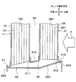
- the first plate 51 of the intermediate tank unit 50 is formed by roll forming. Specifically, as shown in FIG. 9, a strip-shaped first thin plate 710 is prepared as a roll material 711. A plurality of insertion holes 511 and 512 that are a plurality of through holes are formed by roll forming the roll material 711 with a first roll mold 712. Then, the first thin plate 710 in which the plurality of insertion holes 511 and 512 are formed is cut into a predetermined reference first length by the cutter 713. Thereby, the first plate 51 is formed.
- the second plate 52 of the intermediate tank unit 50 is formed by roll forming.
- a belt-like second thin plate 720 is prepared as a roll material 721.
- a plurality of ribs 523 are formed by roll-forming the roll material 721 with the second roll mold 722.
- the second thin plate 720 formed with the plurality of ribs 523 is cut into a predetermined second reference length by the cutter 723. Thereby, the second plate 52 is formed.
- the plurality of first tubes 15 and the plurality of second tubes 25 are temporarily fixed to the first plate 51 and the second plate 52 formed as described above. Further, the fins 30, the first tank part 12, and the second tank part 22 are temporarily fixed to the first tube 15 and the second tube 25 temporarily fixed in this way. Thereby, the temporary assembly in which the various components of the refrigerant evaporator are temporarily fixed is completed.
- this temporary assembly is heated in a heating furnace and brazed. Thereby, the various components of the refrigerant evaporator are joined by brazing, and the refrigerant evaporator is completed.
- a plurality of intermediate flow paths 40 that respectively connect the plurality of sets of tubes 15 and 25 are provided on one end side of the plurality of sets of tubes 15 and 25 in one longitudinal direction.
- the plurality of first tubes 15 and the plurality of second tubes 25 are respectively paired to form a plurality of sets of tubes 15 and 25. That is, one intermediate flow path 40 can be provided for each of the plurality of sets of tubes 15 and 25, and the one set of tubes 15 and 25 can be connected by one intermediate flow path 40.
- the intermediate tank portion with a large internal volume that distributes or collects the refrigerant to the plurality of tubes 15 and 25.
- the intermediate flow path 40 which is a connection part of a set of tubes 15 and 25
- the rapid expansion and contraction of the refrigerant flow path formed inside each of the set of tubes 15 and 25 are suppressed,
- the difference in the refrigerant flow rate between the tubes 15 and 25 and the intermediate flow path 40 can be reduced. Thereby, it is possible to suppress an increase in pressure loss in the intermediate flow path 40 and deterioration of refrigerant distribution to the plurality of second tubes 25.
- the heat exchange efficiency of the refrigerant evaporator can be increased, and the cooling capacity of the vehicle air conditioner can be improved.
- the cooling capacity is the same, it is possible to reduce the power consumption of the compressor and reduce the size and weight of the refrigerant evaporator.
- the cross-sectional area of the nth narrow channel 150n of the first tube 15 is Sn. Further, the cross-sectional area of the n-th outflow portion 46n in the intermediate flow path 40 is Mn.
- the intermediate flow path 40 of this embodiment is comprised so that the relationship of following formula (1) may be satisfy
- k is a natural number of n or less.
- the intermediate flow path 40 of the present embodiment is configured to satisfy the following relationship.
- the intermediate flow path 40 is configured to satisfy the relationship of the following formula (2).
- k is a natural number of n or less.
- the intermediate flow path 40 of the present embodiment is configured to satisfy the following relationship.
- the refrigerant evaporator according to Comparative Example 1 is replaced with a conventional refrigerant evaporator that has an intermediate tank portion with a large internal volume that distributes or collects refrigerant to the plurality of first tubes 15 and the plurality of second tubes 25. That's it.
- a plurality of first tubes 15 and a plurality of second tubes are obtained by the presence of a gas-liquid two-phase refrigerant in the intermediate tank and the ratio of the gas phase and the liquid phase of the refrigerant flowing through the tubes 15 and 25 being different.
- the pressure difference between the inlet and the outlet differs between the two and the refrigerant flows through the plurality of first tubes 15 and the plurality of second tubes 25 are biased. For this reason, there exists a possibility that refrigerant distribution may deteriorate.
- the liquid level of the refrigerant may reach the outlet part to the second tube 25 in the intermediate tank part.
- abnormal noise may occur when the refrigerant flows out.
- the first tube 15 of the first core portion 11 and the second tube 25 of the second core portion 21 are connected by the intermediate flow path 40 having a small internal volume. For this reason, even when the refrigerant flow rate is small, the liquid-phase refrigerant and the refrigerating machine oil that flow into the intermediate flow path 40 flow out to the second tube 25 without stagnation. Thereby, the refrigerant
- the refrigerant evaporator is attached by connecting the first tube 15 of the first core portion 11 and the second tube 25 of the second core portion 21 one by one through the intermediate flow path 40. Even when the angle (posture) is inclined from the vertical, the distribution amount of the refrigerant flowing into each second tube 25 does not change and can be maintained uniform. For this reason, the cooling capacity of the vehicle air conditioner can be maintained.
- the refrigerant evaporator of the comparative example 2 is a conventional refrigerant evaporator configured by superimposing three plate materials of the first plate material, the second plate material, and the third plate material on the intermediate flow path 40. That's it.
- the intermediate flow path 40 is constituted by the three plate members, so that the number of parts increases.
- the second plate material for forming the intermediate flow path is formed by subjecting a flat metal material to press punching. Therefore, the flow path area of the intermediate flow path depends on the thickness of the second plate material. However, since the thickness of the second plate material is generally thin, the flow passage area of the intermediate flow passage cannot be increased, and the pressure loss increases. Although it is conceivable to increase the thickness of the second plate material to increase the flow channel area of the intermediate flow channel, the required amount of material for the second plate material increases, resulting in an increase in weight or processing. There is a risk that the property will deteriorate and the material cost will increase.
- brazing and joining a plurality of tubes and three plate materials when brazing and joining a plurality of tubes and three plate materials, the heat capacity of each of the three plate materials is large, and the heat capacity and heat transfer method of the members to be joined differ greatly. For this reason, brazing conditions become severe and manufacture becomes difficult.
- the intermediate flow path 40 is constituted by the first plate 51 and the second plate 52.
- the increase in the number of parts can be suppressed.
- the amount of material used required for constituting the refrigerant evaporator can be reduced, weight reduction can be achieved and deterioration of workability can be suppressed. For this reason, material cost and processing cost can be reduced.
- first tank 51 and the second plate 52 are brazed by configuring the intermediate tank portion 50 (the first plate 51 and the second plate 52) with two thin plates 710 and 720 having a small heat capacity and a small deviation. Can be joined. For this reason, in the intermediate tank part 50, reliable airtight sealing can be performed by an easy method of brazing.
- first plate 51 and the second plate 52 by roll forming, continuous processing using the roll molds 712 and 722 becomes possible. For this reason, since the production rate of the intermediate tank unit 50 can be increased, a large amount of refrigerant evaporators can be produced in the same time.
- the thin plates 710 and 720 are made to have plate lengths corresponding to the cooling capacity. It is possible to cope with a simple method of cutting. For this reason, design man-hours and manufacturing setup man-hours can be simplified.
- the rigidity of the second plate 52 can be improved by the rib effect. For this reason, since the thickness of the second plate 52 can be reduced, the weight of the refrigerant evaporator can be reduced.
- the cross-sectional area of the first tube 15 is smaller than the cross-sectional area of the second tube 25.
- the length of the air flow direction X in the first tube 15 is shorter than the length of the air flow direction X in the second tube 25.
- the number of narrow channels 150 in the first tube 15 is smaller than the number of narrow channels 250 in the second tube 25.
- the cross-sectional area of the first tube 15 through which a large amount of liquid-phase refrigerant flows is reduced, and the cross-sectional area of the second tube 25 through which a large amount of gas-phase refrigerant flows. Can be bigger. For this reason, since the refrigerant
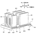
- FIGS. 13 and 14 a third embodiment of the present disclosure will be described based on FIGS. 13 and 14.
- the third embodiment is different from the first embodiment in the shape of the intermediate tank portion 50 and the like.
- the shapes of the plurality of intermediate flow paths 40 arranged in the tube stacking direction, that is, the ribs 523 are different from each other.
- the plurality of intermediate flow paths 40 (the plurality of ribs 523) have different lengths in the tube longitudinal direction. Thereby, the flow path areas of the plurality of intermediate flow paths 40 are different from each other.
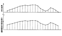
- the flow path area of the intermediate flow path 40 is larger as the air-side heat load is larger. More specifically, as shown in FIG. 14, in the intermediate tank unit 50, the flow area of the intermediate flow path 40 is larger as the air velocity is higher. That is, the longer the air velocity, the longer the length in the tube longitudinal direction of the intermediate flow path 40 (rib 523). Note that the lengths in the tube stacking direction of the plurality of intermediate flow paths 40 (the plurality of ribs 523) are equal.
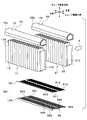
- FIG. 10 (Fourth embodiment) Next, a fourth embodiment of the present disclosure will be described based on FIG.
- the fourth embodiment differs from the first embodiment in the shape of the first tank portion 12 and the like.
- illustration of the fin 30 is abbreviate
- the first tank portion 12 of the present embodiment has a refrigerant outlet portion 12b formed on one end side in the tube stacking direction (the right side of the drawing in FIG. 15).
- the refrigerant derivation unit 12b derives the refrigerant from the inside of the tank of the first tank unit 12 to the suction side of a compressor (not shown).
- a partition member 120 that partitions the tank internal space of the first tank portion 12 into two in the tube stacking direction is provided inside the first tank portion 12.
- the partition member 120 partitions the tank internal space of the first tank portion 12 into a first space 121 and a second space 122.
- the partition member 120 is disposed closer to the refrigerant introduction part 12a than the central part in the tube stacking direction in the first tank part 12.
- the first space 121 communicates with the refrigerant introduction part 12a.
- the refrigerant introduction part 12a constitutes an inflow part through which the refrigerant flows into the first space 121 from the outside.
- the second space 122 communicates with the refrigerant outlet 12b.
- the refrigerant derivation part 12b constitutes an outflow part for allowing the refrigerant to flow out from the second space 122 to the outside.
- the first tube 15 communicating with the first space 121 is referred to as a first inflow side tube 15 a
- the first tube 15 communicating with the second space 122 is referred to as the first tube 15.
- This is referred to as the first outflow side tube 15b.
- the second tube 25 facing the first inflow side tube 15a that is, the second tube disposed on the upstream side of the air flow of the first inflow side tube 15a. 25 is referred to as a second inflow side tube 25a.
- the second tube 25 facing the second outflow side tube 15b that is, the second tube 25 arranged on the upstream side of the air flow of the second outflow side tube 15b is provided.
- the second outflow side tube 25b is provided.
- the low-pressure refrigerant decompressed by the expansion valve is introduced into the first space 121 from the refrigerant introduction part 12a formed on the other end side in the tube stacking direction of the first tank part 12 as indicated by an arrow a.
- the refrigerant introduced into the first space 121 descends the first inflow side tube 15a of the first core portion 11 as indicated by an arrow b.
- the refrigerant descending the first inflow side tube 15a flows through the intermediate flow path 40 of the intermediate tank portion 50 from the downstream side toward the upstream side, as indicated by an arrow c, and the second inflow side tube of the second core portion 21. Flows into 25a.
- the refrigerant flowing into the second inflow side tube 25a ascends the second inflow side tube 25a as shown by an arrow d and flows into the second tank portion 22.
- the refrigerant flowing into the second tank part 22 flows from the other end side in the tube stacking direction toward the one end side (from the left side to the right side in FIG. 15) in the second tank part 22 as indicated by an arrow e.
- the refrigerant flowing into the second outflow side tube 25b descends the second outflow side tube 25b as shown by the arrow f and flows into the intermediate flow path 40 of the intermediate tank unit 50.
- the refrigerant that has flowed into the intermediate flow path 40 flows through the intermediate flow path 40 from the upstream side to the downstream side as indicated by an arrow g, and flows into the first outflow side tube 15b of the first core portion 11.
- the refrigerant flowing into the first outflow side tube 15b ascends the first outflow side tube 15b as shown by an arrow h and flows into the second space 122 of the first tank portion 12.
- the refrigerant that has flowed into the second space 122 is led out to the compressor suction side from a refrigerant lead-out portion 12b formed on one end side in the tube stacking direction of the first tank portion 12 as indicated by an arrow i.
- the number of tubes 15 and 25 used on the upstream side of the refrigerant flow is reduced and used on the downstream side of the refrigerant flow.
- the number of tubes 15 and 25 to be increased can be increased.
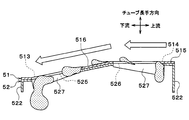
- FIGS. 16, 17, 18, and 19 a fifth embodiment of the present disclosure will be described based on FIGS. 16, 17, 18, and 19.
- the fifth embodiment is different from the first embodiment in that a configuration for improving drainage from the intermediate tank unit 50 is provided.
- illustration of the fins 30 is omitted.
- a drain hole 513 that is a through-hole penetrating both the first plate 51 and the second plate 52 is provided in a portion of the first plate 51 and the second plate 52 that does not constitute the intermediate flow path 40. 514, 525, and 526 are provided.
- the first plate 51 is formed with drain holes 513 and 514 for discharging condensed water. Further, drain holes 525 and 526 for discharging condensed water are formed in the second plate 52. The drain holes 525 and 526 of the second plate 52 are disposed at portions corresponding to the drain holes 513 and 514 of the first plate 51.
- the condensed water generated in the core portions 11 and 21 descends through the tubes 15 and 25 or the fins 30 and is discharged to the lower side of the refrigerant evaporator through the drain holes 513, 514, 525, and 526. .
- first drain holes 513 are provided between adjacent first insertion holes 511 in the first plate 51.
- a second drain hole 514 is provided between the adjacent second insertion holes 512 in the first plate 51.
- the first drain hole 513 and the second drain hole 514 are through holes that penetrate the front and back of the first plate 51.
- the first drain hole 513 and the second drain hole 514 are formed in a triangular shape. Specifically, the first drain hole 513 is formed in an isosceles triangle shape having a base on the downstream side of the air flow. The second drain hole 514 is formed in an isosceles triangle shape having a base on the upstream side of the air flow.
- a third drain hole 525 and a fourth drain hole 526 are provided between adjacent ribs 523 in the second plate 52.
- the third drain hole 525 and the fourth drain hole 526 are arranged side by side in the air flow direction X.
- the third drain hole 525 is disposed on the downstream side of the air flow with respect to the fourth drain hole 526.
- the third drain hole 525 and the fourth drain hole 526 are through holes that penetrate the front and back of the second plate 52.
- the third drain hole 525 is disposed at a portion corresponding to the first drain hole 513 of the first plate 51.
- the third drain hole 525 is formed in the same shape as the first drain hole 513. That is, the third drain hole 525 is formed in an isosceles triangle shape having a base on the downstream side of the air flow.
- the fourth drain hole 526 is disposed at a portion corresponding to the second drain hole 514 of the first plate 51. When viewed from the tube longitudinal direction, the fourth drain hole 526 is formed in the same shape as the second drain hole 514. That is, the fourth drain hole 526 is formed in an isosceles triangle shape having a base on the upstream side of the air flow.
- a cut-and-raised portion 527 cut and raised toward the lower side is provided on the outer peripheral edge portion of the third drain hole 525.
- the cut and raised portion 527 is a portion that is cut and raised when the third drain hole 525 is formed by roll forming.
- the cut-and-raised portions 527 are respectively connected to two equal sides of the third drainage hole 525 having an isosceles triangle shape.
- a similar raised portion 527 is also provided at the outer peripheral edge of the fourth drain hole 526.
- the condensed water generated in the core portions 11 and 21 is discharged to the drain holes 513, 514, and 525. 526 can be discharged.
- drain holes 513, 514, 525, and 526 can be formed in addition to the insertion holes 511 and 512 and the rib 523 in the first plate 51 and the second plate 52. Become.
- the cut-and-raised part 527 is provided in the outer peripheral edge part of the drain holes 525 and 526 of the second plate 52. Therefore, the water drainage of the water droplet dripped from the drain holes 525 and 526 can be improved.
- the first plate 51 of the present embodiment is configured to have a flat surface 515 and an inclined surface 516.
- the flat surface 515 is a surface that is orthogonal to the longitudinal direction of the tube, that is, that extends in the horizontal direction.
- a second insertion hole 512 is formed in the flat surface 515.
- the inclined surface 516 is gradually inclined downward toward the downstream side of the air flow.
- a first insertion hole 511 is formed in the inclined surface 516.
- the inclined surface 516 is connected to the air flow downstream side of the flat surface 515. Further, the flat surface 515 and the inclined surface 516 are integrally formed.
- the inclined surface 516 that is gradually inclined downward toward the air flow downstream side is provided on the air flow downstream side of the first plate 51, the drainage of the condensed water is further improved. Can do.
- the intermediate tank unit 50 is arranged on one end side (lower end side) of the core units 11 and 21 in the tube longitudinal direction, but the arrangement of the intermediate tank unit 50 is not limited thereto.
- the intermediate tank portion 50 may be disposed on the other end side (upper end side) of the core portions 11 and 21 in the tube longitudinal direction.
- the rib 523 has a substantially U-shaped cross section when viewed from the air flow direction X
- the shape of the rib 523 is not limited thereto.
- the rib 523 may have a substantially V-shaped cross section viewed from the air flow direction X.
- the fin 30 is joined to both the pair of tubes 15 and 25 has been described, but the arrangement of the fin 30 is not limited thereto.
- the fins 30 joined to the first tubes 15 adjacent in the tube stacking direction and the fins 30 joined to the second tubes 25 adjacent in the tube stacking direction may be provided separately.
- the intermediate tank unit 50 may be configured such that the flow path area of the intermediate flow path 40 changes according to the temperature distribution (humidity distribution) of air. Specifically, the flow channel area of the intermediate flow channel 40 may be increased as the temperature (humidity) of the air is higher.
- the example in which the cut and raised portions 527 are provided on the outer peripheral edge portions of the third drain hole 525 and the fourth drain hole 526 of the second plate 52 has been described.
- the configurations of the drain holes 525 and the fourth drain holes 526 are not limited to this.
- the cut-and-raised portion 527 may not be provided on the outer peripheral edge portions of the third drain hole 525 and the fourth drain hole 526.
Landscapes
- Engineering & Computer Science (AREA)
- Physics & Mathematics (AREA)
- Mechanical Engineering (AREA)
- Thermal Sciences (AREA)
- General Engineering & Computer Science (AREA)
- Geometry (AREA)
- Heat-Exchange Devices With Radiators And Conduit Assemblies (AREA)
Priority Applications (3)
| Application Number | Priority Date | Filing Date | Title |
|---|---|---|---|
| CN201880031072.9A CN110651162B (zh) | 2017-05-10 | 2018-04-16 | 制冷剂蒸发器及其制造方法 |
| DE112018002406.7T DE112018002406T5 (de) | 2017-05-10 | 2018-04-16 | Kältemittelverdampfer und Verfahren zu dessen Herstellung |
| US16/654,086 US11346584B2 (en) | 2017-05-10 | 2019-10-16 | Refrigerant evaporator and method for manufacturing same |
Applications Claiming Priority (2)
| Application Number | Priority Date | Filing Date | Title |
|---|---|---|---|
| JP2017-094153 | 2017-05-10 | ||
| JP2017094153A JP6717256B2 (ja) | 2017-05-10 | 2017-05-10 | 冷媒蒸発器およびその製造方法 |
Related Child Applications (1)
| Application Number | Title | Priority Date | Filing Date |
|---|---|---|---|
| US16/654,086 Continuation US11346584B2 (en) | 2017-05-10 | 2019-10-16 | Refrigerant evaporator and method for manufacturing same |
Publications (1)
| Publication Number | Publication Date |
|---|---|
| WO2018207556A1 true WO2018207556A1 (ja) | 2018-11-15 |
Family
ID=64104456
Family Applications (1)
| Application Number | Title | Priority Date | Filing Date |
|---|---|---|---|
| PCT/JP2018/015659 Ceased WO2018207556A1 (ja) | 2017-05-10 | 2018-04-16 | 冷媒蒸発器およびその製造方法 |
Country Status (5)
| Country | Link |
|---|---|
| US (1) | US11346584B2 (https=) |
| JP (1) | JP6717256B2 (https=) |
| CN (1) | CN110651162B (https=) |
| DE (1) | DE112018002406T5 (https=) |
| WO (1) | WO2018207556A1 (https=) |
Cited By (2)
| Publication number | Priority date | Publication date | Assignee | Title |
|---|---|---|---|---|
| CN112240714A (zh) * | 2019-07-19 | 2021-01-19 | 广州汽车集团股份有限公司 | 一种蒸发器 |
| JP7701779B2 (ja) | 2019-11-22 | 2025-07-02 | 株式会社富士通ゼネラル | 熱交換器 |
Families Citing this family (4)
| Publication number | Priority date | Publication date | Assignee | Title |
|---|---|---|---|---|
| KR20230089605A (ko) * | 2021-12-13 | 2023-06-21 | 삼성전자주식회사 | 열 교환기 및 이를 포함하는 열 교환 시스템 |
| JP2024046157A (ja) * | 2022-09-22 | 2024-04-03 | パナソニックIpマネジメント株式会社 | 熱交換器、及び室外機 |
| CN116817630A (zh) * | 2023-07-13 | 2023-09-29 | 河北秦淮数据有限公司 | 换热器及换热系统 |
| CN116907131B (zh) * | 2023-08-22 | 2026-03-10 | 珠海格力节能环保制冷技术研究中心有限公司 | 分流器及具有其的空调器 |
Citations (10)
| Publication number | Priority date | Publication date | Assignee | Title |
|---|---|---|---|---|
| JP2004053132A (ja) * | 2002-07-19 | 2004-02-19 | Denso Corp | 冷却器 |
| JP2004163036A (ja) * | 2002-11-14 | 2004-06-10 | Japan Climate Systems Corp | 複列型熱交換器 |
| JP2007057176A (ja) * | 2005-08-25 | 2007-03-08 | Calsonic Kansei Corp | 熱交換器 |
| JP2008025956A (ja) * | 2006-07-25 | 2008-02-07 | Showa Denko Kk | 熱交換器 |
| JP2009014282A (ja) * | 2007-07-05 | 2009-01-22 | Japan Climate Systems Corp | 熱交換器 |
| JP2009275956A (ja) * | 2008-05-13 | 2009-11-26 | Denso Corp | 熱交換器 |
| JP2011214827A (ja) * | 2010-03-31 | 2011-10-27 | Modine Manufacturing Co | 熱交換器 |
| WO2011161918A1 (ja) * | 2010-06-25 | 2011-12-29 | 株式会社デンソー | 熱交換器 |
| JP2015152209A (ja) * | 2014-02-13 | 2015-08-24 | パナソニックIpマネジメント株式会社 | 熱交換器 |
| WO2015189990A1 (ja) * | 2014-06-13 | 2015-12-17 | 三菱電機株式会社 | 熱交換器 |
Family Cites Families (12)
| Publication number | Priority date | Publication date | Assignee | Title |
|---|---|---|---|---|
| DE9400687U1 (de) * | 1994-01-17 | 1995-05-18 | Thermal-Werke, Wärme-, Kälte-, Klimatechnik GmbH, 68766 Hockenheim | Verdampfer für Klimaanlagen in Kraftfahrzeugen mit Mehrkammerflachrohren |
| TW552382B (en) * | 2001-06-18 | 2003-09-11 | Showa Dendo Kk | Evaporator, manufacturing method of the same, header for evaporator and refrigeration system |
| JP2005513403A (ja) | 2001-12-21 | 2005-05-12 | ベール ゲーエムベーハー ウント コー カーゲー | 特に自動車用の熱交換器 |
| JP4124136B2 (ja) * | 2003-04-21 | 2008-07-23 | 株式会社デンソー | 冷媒蒸発器 |
| JP4193741B2 (ja) | 2004-03-30 | 2008-12-10 | 株式会社デンソー | 冷媒蒸発器 |
| JP2008116102A (ja) * | 2006-11-02 | 2008-05-22 | Denso Corp | 冷却用熱交換器 |
| JP5136050B2 (ja) * | 2007-12-27 | 2013-02-06 | 株式会社デンソー | 熱交換器 |
| WO2012105524A1 (ja) | 2011-01-31 | 2012-08-09 | 味の素株式会社 | 複室容器 |
| JP5796564B2 (ja) * | 2011-11-30 | 2015-10-21 | 株式会社デンソー | 熱交換器 |
| JP6050978B2 (ja) * | 2012-07-23 | 2016-12-21 | 株式会社ケーヒン・サーマル・テクノロジー | エバポレータ |
| EP3064880B1 (en) * | 2013-10-30 | 2021-03-24 | Mitsubishi Electric Corporation | Laminated header, heat exchanger, and air-conditioning apparatus |
| JP6341099B2 (ja) | 2015-01-14 | 2018-06-13 | 株式会社デンソー | 冷媒蒸発器 |
-
2017
- 2017-05-10 JP JP2017094153A patent/JP6717256B2/ja not_active Expired - Fee Related
-
2018
- 2018-04-16 DE DE112018002406.7T patent/DE112018002406T5/de not_active Withdrawn
- 2018-04-16 CN CN201880031072.9A patent/CN110651162B/zh not_active Expired - Fee Related
- 2018-04-16 WO PCT/JP2018/015659 patent/WO2018207556A1/ja not_active Ceased
-
2019
- 2019-10-16 US US16/654,086 patent/US11346584B2/en active Active
Patent Citations (10)
| Publication number | Priority date | Publication date | Assignee | Title |
|---|---|---|---|---|
| JP2004053132A (ja) * | 2002-07-19 | 2004-02-19 | Denso Corp | 冷却器 |
| JP2004163036A (ja) * | 2002-11-14 | 2004-06-10 | Japan Climate Systems Corp | 複列型熱交換器 |
| JP2007057176A (ja) * | 2005-08-25 | 2007-03-08 | Calsonic Kansei Corp | 熱交換器 |
| JP2008025956A (ja) * | 2006-07-25 | 2008-02-07 | Showa Denko Kk | 熱交換器 |
| JP2009014282A (ja) * | 2007-07-05 | 2009-01-22 | Japan Climate Systems Corp | 熱交換器 |
| JP2009275956A (ja) * | 2008-05-13 | 2009-11-26 | Denso Corp | 熱交換器 |
| JP2011214827A (ja) * | 2010-03-31 | 2011-10-27 | Modine Manufacturing Co | 熱交換器 |
| WO2011161918A1 (ja) * | 2010-06-25 | 2011-12-29 | 株式会社デンソー | 熱交換器 |
| JP2015152209A (ja) * | 2014-02-13 | 2015-08-24 | パナソニックIpマネジメント株式会社 | 熱交換器 |
| WO2015189990A1 (ja) * | 2014-06-13 | 2015-12-17 | 三菱電機株式会社 | 熱交換器 |
Cited By (2)
| Publication number | Priority date | Publication date | Assignee | Title |
|---|---|---|---|---|
| CN112240714A (zh) * | 2019-07-19 | 2021-01-19 | 广州汽车集团股份有限公司 | 一种蒸发器 |
| JP7701779B2 (ja) | 2019-11-22 | 2025-07-02 | 株式会社富士通ゼネラル | 熱交換器 |
Also Published As
| Publication number | Publication date |
|---|---|
| JP6717256B2 (ja) | 2020-07-01 |
| CN110651162B (zh) | 2021-12-07 |
| DE112018002406T5 (de) | 2020-01-23 |
| US20200049382A1 (en) | 2020-02-13 |
| US11346584B2 (en) | 2022-05-31 |
| CN110651162A (zh) | 2020-01-03 |
| JP2018189337A (ja) | 2018-11-29 |
Similar Documents
| Publication | Publication Date | Title |
|---|---|---|
| WO2018207556A1 (ja) | 冷媒蒸発器およびその製造方法 | |
| US10337808B2 (en) | Condenser | |
| WO2014041771A1 (ja) | 熱交換器 | |
| WO2008079135A1 (en) | Heat exchanger design for improved performance and manufacturability | |
| JP6341099B2 (ja) | 冷媒蒸発器 | |
| JP6558269B2 (ja) | 冷媒蒸発器 | |
| WO2014068842A1 (ja) | 冷媒蒸発器 | |
| CN107208948B (zh) | 制冷剂蒸发器 | |
| WO2014188689A1 (ja) | 冷媒蒸発器 | |
| JP2013024517A (ja) | 積層型熱交換器 | |
| JP6842915B2 (ja) | エバポレータ | |
| JP6558268B2 (ja) | 冷媒蒸発器 | |
| KR20170011736A (ko) | 열교환기용 튜브 | |
| JP6322982B2 (ja) | 冷媒蒸発器 | |
| JP2007078292A (ja) | 熱交換器および複式熱交換器 | |
| JP2010107131A (ja) | 冷媒蒸発器 | |
| JPH03247992A (ja) | 積層型熱交換器 | |
| JP6613996B2 (ja) | 冷媒蒸発器 | |
| WO2014181547A1 (ja) | 冷媒蒸発器 | |
| US20200217589A1 (en) | Tube assembly for heat management apparatus and method of manufacturing the same | |
| JPWO2006129598A1 (ja) | 熱交換器 | |
| JP6432275B2 (ja) | 冷媒蒸発器 | |
| JP2008256248A (ja) | 冷却用熱交換器 | |
| JP2007178017A (ja) | 熱交換器 | |
| JP2006284163A (ja) | 一体型熱交換装置 |
Legal Events
| Date | Code | Title | Description |
|---|---|---|---|
| 121 | Ep: the epo has been informed by wipo that ep was designated in this application |
Ref document number: 18798503 Country of ref document: EP Kind code of ref document: A1 |
|
| 122 | Ep: pct application non-entry in european phase |
Ref document number: 18798503 Country of ref document: EP Kind code of ref document: A1 |