WO2018207556A1 - 冷媒蒸発器およびその製造方法 - Google Patents
冷媒蒸発器およびその製造方法 Download PDFInfo
- Publication number
- WO2018207556A1 WO2018207556A1 PCT/JP2018/015659 JP2018015659W WO2018207556A1 WO 2018207556 A1 WO2018207556 A1 WO 2018207556A1 JP 2018015659 W JP2018015659 W JP 2018015659W WO 2018207556 A1 WO2018207556 A1 WO 2018207556A1
- Authority
- WO
- WIPO (PCT)
- Prior art keywords
- tubes
- refrigerant
- plate
- tube
- flow
- Prior art date
Links
Images


Classifications
-
- F—MECHANICAL ENGINEERING; LIGHTING; HEATING; WEAPONS; BLASTING
- F28—HEAT EXCHANGE IN GENERAL
- F28D—HEAT-EXCHANGE APPARATUS, NOT PROVIDED FOR IN ANOTHER SUBCLASS, IN WHICH THE HEAT-EXCHANGE MEDIA DO NOT COME INTO DIRECT CONTACT
- F28D1/00—Heat-exchange apparatus having stationary conduit assemblies for one heat-exchange medium only, the media being in contact with different sides of the conduit wall, in which the other heat-exchange medium is a large body of fluid, e.g. domestic or motor car radiators
- F28D1/02—Heat-exchange apparatus having stationary conduit assemblies for one heat-exchange medium only, the media being in contact with different sides of the conduit wall, in which the other heat-exchange medium is a large body of fluid, e.g. domestic or motor car radiators with heat-exchange conduits immersed in the body of fluid
- F28D1/04—Heat-exchange apparatus having stationary conduit assemblies for one heat-exchange medium only, the media being in contact with different sides of the conduit wall, in which the other heat-exchange medium is a large body of fluid, e.g. domestic or motor car radiators with heat-exchange conduits immersed in the body of fluid with tubular conduits
- F28D1/053—Heat-exchange apparatus having stationary conduit assemblies for one heat-exchange medium only, the media being in contact with different sides of the conduit wall, in which the other heat-exchange medium is a large body of fluid, e.g. domestic or motor car radiators with heat-exchange conduits immersed in the body of fluid with tubular conduits the conduits being straight
- F28D1/0535—Heat-exchange apparatus having stationary conduit assemblies for one heat-exchange medium only, the media being in contact with different sides of the conduit wall, in which the other heat-exchange medium is a large body of fluid, e.g. domestic or motor car radiators with heat-exchange conduits immersed in the body of fluid with tubular conduits the conduits being straight the conduits having a non-circular cross-section
- F28D1/05366—Assemblies of conduits connected to common headers, e.g. core type radiators
- F28D1/05391—Assemblies of conduits connected to common headers, e.g. core type radiators with multiple rows of conduits or with multi-channel conduits combined with a particular flow pattern, e.g. multi-row multi-stage radiators
-
- F—MECHANICAL ENGINEERING; LIGHTING; HEATING; WEAPONS; BLASTING
- F25—REFRIGERATION OR COOLING; COMBINED HEATING AND REFRIGERATION SYSTEMS; HEAT PUMP SYSTEMS; MANUFACTURE OR STORAGE OF ICE; LIQUEFACTION SOLIDIFICATION OF GASES
- F25B—REFRIGERATION MACHINES, PLANTS OR SYSTEMS; COMBINED HEATING AND REFRIGERATION SYSTEMS; HEAT PUMP SYSTEMS
- F25B5/00—Compression machines, plants or systems, with several evaporator circuits, e.g. for varying refrigerating capacity
- F25B5/04—Compression machines, plants or systems, with several evaporator circuits, e.g. for varying refrigerating capacity arranged in series
-
- F—MECHANICAL ENGINEERING; LIGHTING; HEATING; WEAPONS; BLASTING
- F25—REFRIGERATION OR COOLING; COMBINED HEATING AND REFRIGERATION SYSTEMS; HEAT PUMP SYSTEMS; MANUFACTURE OR STORAGE OF ICE; LIQUEFACTION SOLIDIFICATION OF GASES
- F25B—REFRIGERATION MACHINES, PLANTS OR SYSTEMS; COMBINED HEATING AND REFRIGERATION SYSTEMS; HEAT PUMP SYSTEMS
- F25B39/00—Evaporators; Condensers
- F25B39/02—Evaporators
- F25B39/022—Evaporators with plate-like or laminated elements
- F25B39/024—Evaporators with plate-like or laminated elements with elements constructed in the shape of a hollow panel
-
- F—MECHANICAL ENGINEERING; LIGHTING; HEATING; WEAPONS; BLASTING
- F25—REFRIGERATION OR COOLING; COMBINED HEATING AND REFRIGERATION SYSTEMS; HEAT PUMP SYSTEMS; MANUFACTURE OR STORAGE OF ICE; LIQUEFACTION SOLIDIFICATION OF GASES
- F25B—REFRIGERATION MACHINES, PLANTS OR SYSTEMS; COMBINED HEATING AND REFRIGERATION SYSTEMS; HEAT PUMP SYSTEMS
- F25B39/00—Evaporators; Condensers
- F25B39/02—Evaporators
- F25B39/028—Evaporators having distributing means
-
- F—MECHANICAL ENGINEERING; LIGHTING; HEATING; WEAPONS; BLASTING
- F28—HEAT EXCHANGE IN GENERAL
- F28D—HEAT-EXCHANGE APPARATUS, NOT PROVIDED FOR IN ANOTHER SUBCLASS, IN WHICH THE HEAT-EXCHANGE MEDIA DO NOT COME INTO DIRECT CONTACT
- F28D1/00—Heat-exchange apparatus having stationary conduit assemblies for one heat-exchange medium only, the media being in contact with different sides of the conduit wall, in which the other heat-exchange medium is a large body of fluid, e.g. domestic or motor car radiators
- F28D1/02—Heat-exchange apparatus having stationary conduit assemblies for one heat-exchange medium only, the media being in contact with different sides of the conduit wall, in which the other heat-exchange medium is a large body of fluid, e.g. domestic or motor car radiators with heat-exchange conduits immersed in the body of fluid
- F28D1/04—Heat-exchange apparatus having stationary conduit assemblies for one heat-exchange medium only, the media being in contact with different sides of the conduit wall, in which the other heat-exchange medium is a large body of fluid, e.g. domestic or motor car radiators with heat-exchange conduits immersed in the body of fluid with tubular conduits
- F28D1/0408—Multi-circuit heat exchangers, e.g. integrating different heat exchange sections in the same unit or heat exchangers for more than two fluids
- F28D1/0417—Multi-circuit heat exchangers, e.g. integrating different heat exchange sections in the same unit or heat exchangers for more than two fluids with particular circuits for the same heat exchange medium, e.g. with the heat exchange medium flowing through sections having different heat exchange capacities or for heating/cooling the heat exchange medium at different temperatures
-
- F—MECHANICAL ENGINEERING; LIGHTING; HEATING; WEAPONS; BLASTING
- F28—HEAT EXCHANGE IN GENERAL
- F28F—DETAILS OF HEAT-EXCHANGE AND HEAT-TRANSFER APPARATUS, OF GENERAL APPLICATION
- F28F1/00—Tubular elements; Assemblies of tubular elements
- F28F1/02—Tubular elements of cross-section which is non-circular
- F28F1/022—Tubular elements of cross-section which is non-circular with multiple channels
-
- F—MECHANICAL ENGINEERING; LIGHTING; HEATING; WEAPONS; BLASTING
- F28—HEAT EXCHANGE IN GENERAL
- F28F—DETAILS OF HEAT-EXCHANGE AND HEAT-TRANSFER APPARATUS, OF GENERAL APPLICATION
- F28F1/00—Tubular elements; Assemblies of tubular elements
- F28F1/10—Tubular elements and assemblies thereof with means for increasing heat-transfer area, e.g. with fins, with projections, with recesses
- F28F1/12—Tubular elements and assemblies thereof with means for increasing heat-transfer area, e.g. with fins, with projections, with recesses the means being only outside the tubular element
- F28F1/126—Tubular elements and assemblies thereof with means for increasing heat-transfer area, e.g. with fins, with projections, with recesses the means being only outside the tubular element consisting of zig-zag shaped fins
-
- F—MECHANICAL ENGINEERING; LIGHTING; HEATING; WEAPONS; BLASTING
- F28—HEAT EXCHANGE IN GENERAL
- F28F—DETAILS OF HEAT-EXCHANGE AND HEAT-TRANSFER APPARATUS, OF GENERAL APPLICATION
- F28F17/00—Removing ice or water from heat-exchange apparatus
- F28F17/005—Means for draining condensates from heat exchangers, e.g. from evaporators
-
- F—MECHANICAL ENGINEERING; LIGHTING; HEATING; WEAPONS; BLASTING
- F28—HEAT EXCHANGE IN GENERAL
- F28F—DETAILS OF HEAT-EXCHANGE AND HEAT-TRANSFER APPARATUS, OF GENERAL APPLICATION
- F28F9/00—Casings; Header boxes; Auxiliary supports for elements; Auxiliary members within casings
- F28F9/02—Header boxes; End plates
- F28F9/0202—Header boxes having their inner space divided by partitions
- F28F9/0204—Header boxes having their inner space divided by partitions for elongated header box, e.g. with transversal and longitudinal partitions
- F28F9/0214—Header boxes having their inner space divided by partitions for elongated header box, e.g. with transversal and longitudinal partitions having only longitudinal partitions
- F28F9/0217—Header boxes having their inner space divided by partitions for elongated header box, e.g. with transversal and longitudinal partitions having only longitudinal partitions the partitions being separate elements attached to header boxes
-
- F—MECHANICAL ENGINEERING; LIGHTING; HEATING; WEAPONS; BLASTING
- F28—HEAT EXCHANGE IN GENERAL
- F28D—HEAT-EXCHANGE APPARATUS, NOT PROVIDED FOR IN ANOTHER SUBCLASS, IN WHICH THE HEAT-EXCHANGE MEDIA DO NOT COME INTO DIRECT CONTACT
- F28D21/00—Heat-exchange apparatus not covered by any of the groups F28D1/00 - F28D20/00
- F28D2021/0019—Other heat exchangers for particular applications; Heat exchange systems not otherwise provided for
- F28D2021/008—Other heat exchangers for particular applications; Heat exchange systems not otherwise provided for for vehicles
- F28D2021/0085—Evaporators
-
- F—MECHANICAL ENGINEERING; LIGHTING; HEATING; WEAPONS; BLASTING
- F28—HEAT EXCHANGE IN GENERAL
- F28F—DETAILS OF HEAT-EXCHANGE AND HEAT-TRANSFER APPARATUS, OF GENERAL APPLICATION
- F28F9/00—Casings; Header boxes; Auxiliary supports for elements; Auxiliary members within casings
- F28F9/22—Arrangements for directing heat-exchange media into successive compartments, e.g. arrangements of guide plates
- F28F2009/222—Particular guide plates, baffles or deflectors, e.g. having particular orientation relative to an elongated casing or conduit
- F28F2009/224—Longitudinal partitions
Definitions
- the present disclosure relates to a refrigerant evaporator that cools a fluid to be cooled and a manufacturing method thereof.
- the inside of the intermediate tank section has substantially the same cross-sectional area in the refrigerant flow direction (longitudinal direction of the intermediate tank section), and the refrigerant flow rate changes in the process of collecting refrigerant from the tubes and distributing the refrigerant to the tubes. .
- the static pressure applied to the inner wall surface varies depending on the position in the longitudinal direction in the intermediate tank, and a difference occurs between the pressure applied to the inlet and the pressure applied to the outlet in each tube. For this reason, there is a possibility that refrigerant distribution may deteriorate.
- Patent Document 1 two heat exchange core parts are arranged in series with respect to the air flow direction, and two heat exchanger core parts arranged in a superimposed manner when viewed from the air flow direction.
- a refrigerant evaporator in which tubes are connected by an intermediate flow path is disclosed.
- the intermediate flow path is configured by superposing three plate materials of a first plate material, a second plate material, and a third plate material. Specifically, a tube insertion hole into which an end portion of the tube is inserted is formed in the first plate material. A through hole communicating with the tube insertion hole is formed in the second plate material. The third plate material is formed in a flat plate shape without a through hole. Then, when these three plate materials are overlapped, an intermediate flow path is formed by the through hole of the second plate material.
- the first heat exchange core part and the second heat exchange core part are connected to each set of tubes that are superposed when viewed from the air flow direction. Can do. For this reason, since the intermediate tank unit for collecting and distributing the refrigerant with respect to the plurality of tubes can be eliminated, an increase in pressure loss, deterioration of refrigerant distribution, and the like are unlikely to occur.
- the present disclosure suppresses an increase in pressure loss at the connection part of the two core parts while suppressing an increase in the number of parts, and It aims at suppressing the deterioration of the refrigerant
- the refrigerant evaporator performs heat exchange between the fluid to be cooled and the refrigerant.
- the refrigerant evaporator includes a first evaporator, a second evaporator, a first core, a second core, a first plate, and a second plate.
- the first evaporator is configured so that the fluid to be cooled passes through the inside in the flow direction.
- the second evaporator is configured so that the fluid to be cooled passes through the inside in the flow direction, and is disposed in series with the first evaporator in the flow direction.
- the first core part includes a plurality of first tubes through which the refrigerant flows.
- the plurality of first tubes extend in the tube longitudinal direction perpendicular to the flow direction and are laminated in the tube lamination direction perpendicular to both the flow direction and the tube longitudinal direction.
- the second core part includes a plurality of second tubes through which the refrigerant flows.
- the plurality of second tubes extend in the tube longitudinal direction and are stacked in the tube stacking direction.
- the first plate is connected to one end portion of the first core portion and one end portion of the second core portion on one side of the tube longitudinal direction, and is connected to one end portion of the plurality of first tubes and one end portion of the plurality of second tubes. To accommodate.
- the second plate faces the first core portion and the second core portion across the first plate in the tube longitudinal direction, and is joined to the first plate.
- the second plate has a plurality of ribs extending in the flow direction while projecting away from the first core portion and the second core portion in the tube longitudinal direction.
- the plurality of ribs together with the first plate define a plurality of intermediate flow paths therein.
- the plurality of first tubes and the plurality of second tubes are arranged so as to overlap each other when viewed from the flow direction, and are a set of one first tube and one second tube facing each other in the flow direction.
- a plurality of sets of tubes are formed.
- a plurality of intermediate flow paths communicate a plurality of sets of tubes.
- a plurality of intermediate flow paths respectively connect a plurality of sets of tubes. That is, one first tube of the plurality of first tubes and one second tube of the plurality of second tubes can be connected by one intermediate flow path. For this reason, the intermediate tank part with a large internal volume which distributes or aggregates the refrigerant to the plurality of tubes can be eliminated. Then, in a plurality of intermediate flow paths that are connecting portions of the plurality of first tubes and the plurality of second tubes, a rapid expansion of the refrigerant flow paths formed inside the plurality of first tubes and the plurality of second tubes, respectively.
- FIG. 2 is an exploded perspective view of FIG. 1. It is an expansion perspective view which shows a part of 1st core part and 2nd core part in 1st Embodiment. It is an expansion perspective view which shows the intermediate tank part vicinity in 1st Embodiment. It is an expansion perspective view which shows the 1st plate in 1st Embodiment. It is an expansion perspective view which shows the 2nd plate in 1st Embodiment. It is an expanded sectional view showing the middle tank part neighborhood in a 1st embodiment.
- FIG. 8 is a sectional view taken along line VIII-VIII in FIG.
- the refrigerant evaporator according to the present embodiment is applied to a vapor compression refrigeration cycle of a vehicle air conditioner that adjusts the temperature in the passenger compartment, and absorbs heat from the air (blowing air) blown into the passenger compartment to generate a refrigerant (liquid phase). It is a cooling heat exchanger that cools the air by evaporating the refrigerant.
- air corresponds to “cooled fluid”.
- illustration of the fin 30 mentioned later is abbreviate
- the refrigeration cycle includes a compressor, a radiator (condenser), an expansion valve, and the like (not shown) in addition to the refrigerant evaporator 1, and in this embodiment, liquid is received between the radiator and the expansion valve. It is configured as a receiver cycle in which a device is arranged.
- the refrigerant of the refrigeration cycle is mixed with refrigeration oil for lubricating the compressor, and a part of the refrigeration oil circulates in the cycle together with the refrigerant.
- the refrigerant evaporator 1 of the present embodiment includes a first evaporator 10 and a second evaporator that are arranged in series with respect to the air flow direction (flow direction of the fluid to be cooled) X.
- the unit 20 is provided.
- the first evaporator 10 is disposed on the downstream side (leeward side) in the air flow direction X with respect to the second evaporator 20.
- the basic configuration of the first evaporator 10 and the second evaporator 20 is the same, and includes the heat exchange core parts 11 and 21 and the tank parts 12 and 22 disposed above the heat exchange core parts 11 and 21, respectively. Configured.
- the heat exchange core part in the first evaporator 10 is referred to as a first core part 11, and the heat exchange core part in the second evaporator 20 is referred to as a second core part 21.
- the tank part in the first evaporator 10 is referred to as a first tank part 12, and the tank part in the second evaporator 20 is referred to as a second tank part 22.
- each of the first core portion 11 and the second core portion 21 a plurality of tubes 15 and 25 extending in the vertical direction and fins 30 (see FIG. 3) joined between the adjacent tubes 15 and 25 are alternately stacked. It is comprised by the laminated body arrange
- the stacking direction in the stacked body of the plurality of tubes 15 and 25 and the plurality of fins 30 is referred to as a tube stacking direction.
- a plurality of tubes constituting the first core portion 11 are referred to as a plurality of first tubes 15, and a plurality of tubes constituting the second core portion 21 are referred to as a plurality of second tubes 25.
- the longitudinal direction of each of the plurality of first tubes 15 and the plurality of second tubes 25 is referred to as a tube longitudinal direction.
- the plurality of first tubes 15 since the plurality of first tubes 15 have the same configuration, the plurality of first tubes 15 may be collectively referred to as the first tube 15 in the following description. Further, since the plurality of second tubes 25 have the same configuration, the plurality of second tubes 25 may be collectively referred to as the second tube 25 in the following description.
- a refrigerant passage through which a refrigerant flows is formed in each of the first tube 15 and the second tube 25.
- the first tube 15 and the second tube 25 are each formed of a flat tube having a flat shape with a cross-sectional shape extending along the air flow direction X.
- the first tube 15 and the second tube 25 are arranged so as to overlap each other when viewed from the air flow direction X.
- the first tube 15 and the second tube 25 that is superposed when viewed from the air flow direction X with respect to the first tube 15 are referred to as a pair of tubes 15 and 25.
- the refrigerant evaporator 1 has a plurality of sets of tubes 15 and 25.
- An intermediate flow path 40 that connects the pair of tubes 15 and 25 to each other is provided on one end side in the tube longitudinal direction of the pair of tubes 15 and 25.
- the intermediate flow path 40 is disposed on the lower end side of the pair of tubes 15 and 25.
- a plurality of intermediate flow paths 40 are provided below the first core portion 11 and the second core portion 21.
- the plurality of intermediate flow paths 40 are arranged side by side in the tube stacking direction. The details of the intermediate flow path 40 will be described later.
- the other end side (upper end side) of the first tube 15 in the longitudinal direction of the tube is connected to the first tank portion 12.
- the second tube 25 is connected to the second tank portion 22 at the other end side (upper end side) in the tube longitudinal direction.
- the fin 30 is a corrugated fin formed by bending a thin plate material into a wave shape.
- the fin 30 is joined to the flat outer surface side of the first tube 15 and the second tube 25 and functions as a heat exchange promoting part for expanding the heat transfer area between the air and the refrigerant.
- the fin 30 is joined to both the pair of tubes 15 and 25.
- side plates 113 and 213 that reinforce the core portions 11 and 22 are provided at both ends in the tube stacking direction in the stacked body of the first tube 15, the second tube 25, and the fin 30, respectively. Is arranged.
- the side plates 113 and 213 are joined to the fins 30 arranged on the outermost side in the tube stacking direction.
- the first tank portion 12 is constituted by a cylindrical member in which one end side in the tube stacking direction is closed and a refrigerant introduction portion 12a is formed on the other end side in the tube stacking direction.
- the refrigerant introduction part 12a introduces the low-pressure refrigerant decompressed by an expansion valve (not shown) into the tank of the first tank part 12.
- the first tank portion 12 is closed at the left end when viewed from the upstream side of the air flow, and the refrigerant introduction portion 12a is formed at the right end when viewed from the upstream side of the air flow. ing.
- the first tank portion 12 has a through hole (not shown) in which the tube longitudinal direction other end side (upper end side) of each first tube 15 is inserted and joined to the bottom portion.
- the first tank portion 12 is configured such that its internal space communicates with each first tube 15 of the first core portion 11.
- the first tank unit 12 functions as a refrigerant distribution unit that distributes the refrigerant to the first core unit 11.
- the second tank portion 22 is configured by a cylindrical member having one end side in the tube stacking direction closed and a refrigerant outlet portion 22a formed on the other end side in the tube stacking direction.
- the refrigerant derivation unit 22a derives the refrigerant from the inside of the tank of the second tank unit 22 to the suction side of a compressor (not shown).
- the second tank portion 22 is closed at the left end when viewed from the upstream side of the air flow, and the refrigerant outlet portion 22a is formed at the right end when viewed from the upstream side of the air flow. ing.
- the second tank portion 22 has a through hole (not shown) in which the other end side (upper end side) in the tube longitudinal direction of each second tube 25 is inserted and joined at the bottom.
- the second tank portion 22 is configured such that its internal space communicates with each second tube 25 of the second core portion 21.
- the second tank unit 22 functions as a refrigerant collecting unit that collects the refrigerant from the second core unit 21.
- an intermediate tank portion 50 that is a flow path forming member that forms a plurality of intermediate flow paths 40 at one end side (lower end side) in the tube longitudinal direction of the first core section 11 and the second core section 21.
- the intermediate tank unit 50 is formed by combining the first plate 51 and the second plate 52.
- the first plate 51 is formed in a substantially rectangular plate shape. One end (lower end) of each of the first tube 15 and the second tube 25 in the tube longitudinal direction is joined to the first plate 51. Specifically, the first plate 51 has a first insertion hole 511 into which one end of the first tube 15 in the longitudinal direction of the tube is inserted, and a first insertion end of the second tube 25 in the longitudinal direction of the tube. 2 insertion holes 512 are formed. The first insertion hole 511 and the second insertion hole 512 are each formed by burring the first plate 51.
- the second plate 52 has a substantially U-shaped cross section viewed from the tube stacking direction.
- the second plate 52 includes a flat surface portion 521 and two side surface portions 522.
- the flat portion 521 is formed in a substantially rectangular plate shape and extends in a direction perpendicular to the tube longitudinal direction.
- the side surface portions 522 extend from both end portions of the plane portion 521 in the air flow direction X so as to be separated from the first core portion 11 and the second core portion 21 in the tube longitudinal direction.
- the flat surface portion 521 and the two side surface portions 522 are integrally formed.
- the flat portion 521 is formed with a plurality of ribs 523 that protrude in the longitudinal direction of the tube so as to be separated from the first core portion 11 and the second core portion 21 and extend in the air flow direction X.
- a plurality of concave portions 524 that are recessed so as to be separated from the first plate 51 in the tube longitudinal direction are formed on the surface of the flat portion 521 on the first plate 51 side.
- Each recess 524 communicates with a first insertion hole 511 and a second insertion hole 512 into which a pair of tubes 15 and 25 are inserted.
- the portion of the flat portion 521 where the plurality of ribs 523 are not formed is joined to the first plate 51.
- the plurality of recesses 524 of the second plate 52 define a plurality of intermediate flow paths 40 together with the surface of the first plate 51 that faces the plurality of ribs 523.
- the plurality of intermediate flow paths 40 are configured by the inner surfaces of the plurality of ribs 523 in the second plate 52 and the surface of the first plate 51 that faces the plurality of ribs 523.
- each of the plurality of ribs 523 has a substantially U-shaped cross section viewed from the air flow direction X. More specifically, each of the plurality of ribs 523 has a substantially U-shaped cross section as viewed from the air flow direction X over the entire region in the air flow direction X.
- the plurality of ribs 523 since the plurality of ribs 523 have the same configuration, hereinafter, the plurality of ribs 523 are collectively referred to as ribs 523. Since the plurality of intermediate flow paths 40 have the same configuration, the plurality of intermediate flow paths 40 will be collectively referred to as intermediate flow paths 40 hereinafter.
- the intermediate flow path 40 is configured so that the length in the tube stacking direction is constant. For this reason, the cross-sectional area of the intermediate flow path 40 is determined based on the length of the intermediate flow path 40 in the tube longitudinal direction.
- the intermediate flow path 40 includes an upstream portion 41, a midstream portion 42, and a downstream portion 43.
- the upstream part 41, the midstream part 42, and the downstream part 43 are arranged in this order from the refrigerant flow upstream side.
- the cross-sectional area of the midstream portion 42 is larger than both the cross-sectional area of the upstream portion 41 and the cross-sectional area of the downstream portion 43.
- the upstream portion 41 is configured such that the cross-sectional area gradually increases toward the downstream side of the refrigerant flow.
- the upstream portion 41 is configured such that the cross-sectional area linearly increases toward the refrigerant flow downstream side. Specifically, the length in the tube longitudinal direction of the upstream portion 41 is gradually increased toward the refrigerant flow downstream side.
- the upstream portion 41 is disposed on one end side (lower end side) of the first tube 15 in the longitudinal direction of the tube.
- the upstream portion 41 communicates with the first tube 15. For this reason, the refrigerant that has flowed out of the first tube 15 flows into the upstream portion 41.
- the midstream portion 42 is configured to have a constant cross-sectional area toward the downstream side of the refrigerant flow.
- the midstream portion 42 is disposed at a position corresponding to the gap 60 between the first tube 15 and the second tube 25.
- the midstream portion 42 is connected to the upstream portion 41. For this reason, the refrigerant that has flowed out of the upstream portion 41 flows into the midstream portion 42.
- the downstream portion 43 is configured such that the cross-sectional area gradually decreases toward the downstream side of the refrigerant flow.
- the downstream part 43 is comprised so that a cross-sectional area may reduce linearly toward a refrigerant
- the length in the tube longitudinal direction is gradually shortened toward the downstream side of the refrigerant flow.
- the downstream portion 43 is disposed on one end side (lower end side) of the second tube 25 in the tube longitudinal direction.
- the upstream side of the downstream portion 43 in the refrigerant flow is connected to the midstream portion 42. For this reason, the refrigerant flowing out from the midstream portion 42 flows into the downstream portion 43.
- the downstream side of the refrigerant flow in the downstream portion 43 communicates with the second tube 25. For this reason, the refrigerant that has flowed through the downstream portion 43 flows into the second tube 25.
- the first tube 15 has a first partition member 151 that partitions the first refrigerant flow path formed in the first tube 15 into a plurality of narrow flow paths 150 arranged in the air flow direction X.
- the second tube 25 includes a second partition member 251 that partitions the second coolant channel formed in the second tube 25 into a plurality of narrow channels 250 arranged in the air flow direction X.
- the cross-sectional area of the midstream portion 42 of the intermediate flow path 40 is set to 0.3 to 3.0 times the cross-sectional area of the first tube 15 or the second tube 25.
- the cross-sectional area of the midstream portion 42 of the intermediate flow path 40 is the sum of the cross-sectional areas of the plurality of narrow channels 150 in the first tube 15 or the sum of the cross-sectional areas of the plurality of narrow channels 250 in the second tube 25. It is set from 0.3 times to 3.0 times.
- the most upstream portion in the air flow direction X is referred to as the most upstream portion 44.
- the most downstream portion in the air flow direction X is referred to as the most downstream portion 45.
- the most upstream part 44 and the most downstream part 45 are configured such that the cross-sectional area of the intermediate flow path 40 is the smallest.
- the cross-sectional areas of the most upstream portion 44 and the most downstream portion 45 are set to 0.3 to 3.0 times the cross-sectional areas of the plurality of narrow channels 150 and the plurality of narrow channels 250, respectively. ing.
- the cross-sectional areas of the most upstream part 44 and the most downstream part 45 are each 0.3 times the cross-sectional area of one of the plurality of narrow channels 150 or one of the plurality of narrow channels 250. It is set to 3.0 times.
- the plurality of narrow channels 150 in the first tube 15 are configured by a first narrow channel 1501 to an nth narrow channel 150 n (n is a natural number) arranged in order toward the second tube 25.
- the first narrow channel 1501 is located farthest from the second tube 25, and the nth narrow channel 150 n is located closest to the second tube 25.
- the portion of the intermediate flow path 40 where the refrigerant flows immediately after flowing out from the nth narrow flow path 150n is referred to as an nth outflow portion 46n.
- the plurality of narrow channels 150 in the first tube 15 are configured by a first narrow channel 1501 to a seventh narrow channel 1507 arranged in order toward the second tube 25. For this reason, in the intermediate flow path 40, a first outflow portion 461 to a seventh outflow portion 467 arranged in order toward the second tube 25 are configured.
- various components of the refrigerant evaporator that is, the first tube 15, the second tube 25, the fins 30, the first tank unit 12, the second tank unit 22, the first plate 51, the second plate 52, and the like are manufactured.
- a method for manufacturing the first plate 51 and the second plate 52 of the intermediate tank unit 50 will be described in detail.
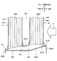
- the first plate 51 of the intermediate tank unit 50 is formed by roll forming. Specifically, as shown in FIG. 9, a strip-shaped first thin plate 710 is prepared as a roll material 711. A plurality of insertion holes 511 and 512 that are a plurality of through holes are formed by roll forming the roll material 711 with a first roll mold 712. Then, the first thin plate 710 in which the plurality of insertion holes 511 and 512 are formed is cut into a predetermined reference first length by the cutter 713. Thereby, the first plate 51 is formed.
- the second plate 52 of the intermediate tank unit 50 is formed by roll forming.
- a belt-like second thin plate 720 is prepared as a roll material 721.
- a plurality of ribs 523 are formed by roll-forming the roll material 721 with the second roll mold 722.
- the second thin plate 720 formed with the plurality of ribs 523 is cut into a predetermined second reference length by the cutter 723. Thereby, the second plate 52 is formed.
- the plurality of first tubes 15 and the plurality of second tubes 25 are temporarily fixed to the first plate 51 and the second plate 52 formed as described above. Further, the fins 30, the first tank part 12, and the second tank part 22 are temporarily fixed to the first tube 15 and the second tube 25 temporarily fixed in this way. Thereby, the temporary assembly in which the various components of the refrigerant evaporator are temporarily fixed is completed.
- this temporary assembly is heated in a heating furnace and brazed. Thereby, the various components of the refrigerant evaporator are joined by brazing, and the refrigerant evaporator is completed.
- a plurality of intermediate flow paths 40 that respectively connect the plurality of sets of tubes 15 and 25 are provided on one end side of the plurality of sets of tubes 15 and 25 in one longitudinal direction.
- the plurality of first tubes 15 and the plurality of second tubes 25 are respectively paired to form a plurality of sets of tubes 15 and 25. That is, one intermediate flow path 40 can be provided for each of the plurality of sets of tubes 15 and 25, and the one set of tubes 15 and 25 can be connected by one intermediate flow path 40.
- the intermediate tank portion with a large internal volume that distributes or collects the refrigerant to the plurality of tubes 15 and 25.
- the intermediate flow path 40 which is a connection part of a set of tubes 15 and 25
- the rapid expansion and contraction of the refrigerant flow path formed inside each of the set of tubes 15 and 25 are suppressed,
- the difference in the refrigerant flow rate between the tubes 15 and 25 and the intermediate flow path 40 can be reduced. Thereby, it is possible to suppress an increase in pressure loss in the intermediate flow path 40 and deterioration of refrigerant distribution to the plurality of second tubes 25.
- the heat exchange efficiency of the refrigerant evaporator can be increased, and the cooling capacity of the vehicle air conditioner can be improved.
- the cooling capacity is the same, it is possible to reduce the power consumption of the compressor and reduce the size and weight of the refrigerant evaporator.
- the cross-sectional area of the nth narrow channel 150n of the first tube 15 is Sn. Further, the cross-sectional area of the n-th outflow portion 46n in the intermediate flow path 40 is Mn.
- the intermediate flow path 40 of this embodiment is comprised so that the relationship of following formula (1) may be satisfy
- k is a natural number of n or less.
- the intermediate flow path 40 of the present embodiment is configured to satisfy the following relationship.
- the intermediate flow path 40 is configured to satisfy the relationship of the following formula (2).
- k is a natural number of n or less.
- the intermediate flow path 40 of the present embodiment is configured to satisfy the following relationship.
- the refrigerant evaporator according to Comparative Example 1 is replaced with a conventional refrigerant evaporator that has an intermediate tank portion with a large internal volume that distributes or collects refrigerant to the plurality of first tubes 15 and the plurality of second tubes 25. That's it.
- a plurality of first tubes 15 and a plurality of second tubes are obtained by the presence of a gas-liquid two-phase refrigerant in the intermediate tank and the ratio of the gas phase and the liquid phase of the refrigerant flowing through the tubes 15 and 25 being different.
- the pressure difference between the inlet and the outlet differs between the two and the refrigerant flows through the plurality of first tubes 15 and the plurality of second tubes 25 are biased. For this reason, there exists a possibility that refrigerant distribution may deteriorate.
- the liquid level of the refrigerant may reach the outlet part to the second tube 25 in the intermediate tank part.
- abnormal noise may occur when the refrigerant flows out.
- the first tube 15 of the first core portion 11 and the second tube 25 of the second core portion 21 are connected by the intermediate flow path 40 having a small internal volume. For this reason, even when the refrigerant flow rate is small, the liquid-phase refrigerant and the refrigerating machine oil that flow into the intermediate flow path 40 flow out to the second tube 25 without stagnation. Thereby, the refrigerant
- the refrigerant evaporator is attached by connecting the first tube 15 of the first core portion 11 and the second tube 25 of the second core portion 21 one by one through the intermediate flow path 40. Even when the angle (posture) is inclined from the vertical, the distribution amount of the refrigerant flowing into each second tube 25 does not change and can be maintained uniform. For this reason, the cooling capacity of the vehicle air conditioner can be maintained.
- the refrigerant evaporator of the comparative example 2 is a conventional refrigerant evaporator configured by superimposing three plate materials of the first plate material, the second plate material, and the third plate material on the intermediate flow path 40. That's it.
- the intermediate flow path 40 is constituted by the three plate members, so that the number of parts increases.
- the second plate material for forming the intermediate flow path is formed by subjecting a flat metal material to press punching. Therefore, the flow path area of the intermediate flow path depends on the thickness of the second plate material. However, since the thickness of the second plate material is generally thin, the flow passage area of the intermediate flow passage cannot be increased, and the pressure loss increases. Although it is conceivable to increase the thickness of the second plate material to increase the flow channel area of the intermediate flow channel, the required amount of material for the second plate material increases, resulting in an increase in weight or processing. There is a risk that the property will deteriorate and the material cost will increase.
- brazing and joining a plurality of tubes and three plate materials when brazing and joining a plurality of tubes and three plate materials, the heat capacity of each of the three plate materials is large, and the heat capacity and heat transfer method of the members to be joined differ greatly. For this reason, brazing conditions become severe and manufacture becomes difficult.
- the intermediate flow path 40 is constituted by the first plate 51 and the second plate 52.
- the increase in the number of parts can be suppressed.
- the amount of material used required for constituting the refrigerant evaporator can be reduced, weight reduction can be achieved and deterioration of workability can be suppressed. For this reason, material cost and processing cost can be reduced.
- first tank 51 and the second plate 52 are brazed by configuring the intermediate tank portion 50 (the first plate 51 and the second plate 52) with two thin plates 710 and 720 having a small heat capacity and a small deviation. Can be joined. For this reason, in the intermediate tank part 50, reliable airtight sealing can be performed by an easy method of brazing.
- first plate 51 and the second plate 52 by roll forming, continuous processing using the roll molds 712 and 722 becomes possible. For this reason, since the production rate of the intermediate tank unit 50 can be increased, a large amount of refrigerant evaporators can be produced in the same time.
- the thin plates 710 and 720 are made to have plate lengths corresponding to the cooling capacity. It is possible to cope with a simple method of cutting. For this reason, design man-hours and manufacturing setup man-hours can be simplified.
- the rigidity of the second plate 52 can be improved by the rib effect. For this reason, since the thickness of the second plate 52 can be reduced, the weight of the refrigerant evaporator can be reduced.
- the cross-sectional area of the first tube 15 is smaller than the cross-sectional area of the second tube 25.
- the length of the air flow direction X in the first tube 15 is shorter than the length of the air flow direction X in the second tube 25.
- the number of narrow channels 150 in the first tube 15 is smaller than the number of narrow channels 250 in the second tube 25.
- the cross-sectional area of the first tube 15 through which a large amount of liquid-phase refrigerant flows is reduced, and the cross-sectional area of the second tube 25 through which a large amount of gas-phase refrigerant flows. Can be bigger. For this reason, since the refrigerant
- FIGS. 13 and 14 a third embodiment of the present disclosure will be described based on FIGS. 13 and 14.
- the third embodiment is different from the first embodiment in the shape of the intermediate tank portion 50 and the like.
- the shapes of the plurality of intermediate flow paths 40 arranged in the tube stacking direction, that is, the ribs 523 are different from each other.
- the plurality of intermediate flow paths 40 (the plurality of ribs 523) have different lengths in the tube longitudinal direction. Thereby, the flow path areas of the plurality of intermediate flow paths 40 are different from each other.
- the flow path area of the intermediate flow path 40 is larger as the air-side heat load is larger. More specifically, as shown in FIG. 14, in the intermediate tank unit 50, the flow area of the intermediate flow path 40 is larger as the air velocity is higher. That is, the longer the air velocity, the longer the length in the tube longitudinal direction of the intermediate flow path 40 (rib 523). Note that the lengths in the tube stacking direction of the plurality of intermediate flow paths 40 (the plurality of ribs 523) are equal.
- FIG. 10 (Fourth embodiment) Next, a fourth embodiment of the present disclosure will be described based on FIG.
- the fourth embodiment differs from the first embodiment in the shape of the first tank portion 12 and the like.
- illustration of the fin 30 is abbreviate
- the first tank portion 12 of the present embodiment has a refrigerant outlet portion 12b formed on one end side in the tube stacking direction (the right side of the drawing in FIG. 15).
- the refrigerant derivation unit 12b derives the refrigerant from the inside of the tank of the first tank unit 12 to the suction side of a compressor (not shown).
- a partition member 120 that partitions the tank internal space of the first tank portion 12 into two in the tube stacking direction is provided inside the first tank portion 12.
- the partition member 120 partitions the tank internal space of the first tank portion 12 into a first space 121 and a second space 122.
- the partition member 120 is disposed closer to the refrigerant introduction part 12a than the central part in the tube stacking direction in the first tank part 12.
- the first space 121 communicates with the refrigerant introduction part 12a.
- the refrigerant introduction part 12a constitutes an inflow part through which the refrigerant flows into the first space 121 from the outside.
- the second space 122 communicates with the refrigerant outlet 12b.
- the refrigerant derivation part 12b constitutes an outflow part for allowing the refrigerant to flow out from the second space 122 to the outside.
- the first tube 15 communicating with the first space 121 is referred to as a first inflow side tube 15 a
- the first tube 15 communicating with the second space 122 is referred to as the first tube 15.
- This is referred to as the first outflow side tube 15b.
- the second tube 25 facing the first inflow side tube 15a that is, the second tube disposed on the upstream side of the air flow of the first inflow side tube 15a. 25 is referred to as a second inflow side tube 25a.
- the second tube 25 facing the second outflow side tube 15b that is, the second tube 25 arranged on the upstream side of the air flow of the second outflow side tube 15b is provided.
- the second outflow side tube 25b is provided.
- the low-pressure refrigerant decompressed by the expansion valve is introduced into the first space 121 from the refrigerant introduction part 12a formed on the other end side in the tube stacking direction of the first tank part 12 as indicated by an arrow a.
- the refrigerant introduced into the first space 121 descends the first inflow side tube 15a of the first core portion 11 as indicated by an arrow b.
- the refrigerant descending the first inflow side tube 15a flows through the intermediate flow path 40 of the intermediate tank portion 50 from the downstream side toward the upstream side, as indicated by an arrow c, and the second inflow side tube of the second core portion 21. Flows into 25a.
- the refrigerant flowing into the second inflow side tube 25a ascends the second inflow side tube 25a as shown by an arrow d and flows into the second tank portion 22.
- the refrigerant flowing into the second tank part 22 flows from the other end side in the tube stacking direction toward the one end side (from the left side to the right side in FIG. 15) in the second tank part 22 as indicated by an arrow e.
- the refrigerant flowing into the second outflow side tube 25b descends the second outflow side tube 25b as shown by the arrow f and flows into the intermediate flow path 40 of the intermediate tank unit 50.
- the refrigerant that has flowed into the intermediate flow path 40 flows through the intermediate flow path 40 from the upstream side to the downstream side as indicated by an arrow g, and flows into the first outflow side tube 15b of the first core portion 11.
- the refrigerant flowing into the first outflow side tube 15b ascends the first outflow side tube 15b as shown by an arrow h and flows into the second space 122 of the first tank portion 12.
- the refrigerant that has flowed into the second space 122 is led out to the compressor suction side from a refrigerant lead-out portion 12b formed on one end side in the tube stacking direction of the first tank portion 12 as indicated by an arrow i.
- the number of tubes 15 and 25 used on the upstream side of the refrigerant flow is reduced and used on the downstream side of the refrigerant flow.
- the number of tubes 15 and 25 to be increased can be increased.
- FIGS. 16, 17, 18, and 19 a fifth embodiment of the present disclosure will be described based on FIGS. 16, 17, 18, and 19.
- the fifth embodiment is different from the first embodiment in that a configuration for improving drainage from the intermediate tank unit 50 is provided.
- illustration of the fins 30 is omitted.
- a drain hole 513 that is a through-hole penetrating both the first plate 51 and the second plate 52 is provided in a portion of the first plate 51 and the second plate 52 that does not constitute the intermediate flow path 40. 514, 525, and 526 are provided.
- the first plate 51 is formed with drain holes 513 and 514 for discharging condensed water. Further, drain holes 525 and 526 for discharging condensed water are formed in the second plate 52. The drain holes 525 and 526 of the second plate 52 are disposed at portions corresponding to the drain holes 513 and 514 of the first plate 51.
- the condensed water generated in the core portions 11 and 21 descends through the tubes 15 and 25 or the fins 30 and is discharged to the lower side of the refrigerant evaporator through the drain holes 513, 514, 525, and 526. .
- first drain holes 513 are provided between adjacent first insertion holes 511 in the first plate 51.
- a second drain hole 514 is provided between the adjacent second insertion holes 512 in the first plate 51.
- the first drain hole 513 and the second drain hole 514 are through holes that penetrate the front and back of the first plate 51.
- the first drain hole 513 and the second drain hole 514 are formed in a triangular shape. Specifically, the first drain hole 513 is formed in an isosceles triangle shape having a base on the downstream side of the air flow. The second drain hole 514 is formed in an isosceles triangle shape having a base on the upstream side of the air flow.
- a third drain hole 525 and a fourth drain hole 526 are provided between adjacent ribs 523 in the second plate 52.
- the third drain hole 525 and the fourth drain hole 526 are arranged side by side in the air flow direction X.
- the third drain hole 525 is disposed on the downstream side of the air flow with respect to the fourth drain hole 526.
- the third drain hole 525 and the fourth drain hole 526 are through holes that penetrate the front and back of the second plate 52.
- the third drain hole 525 is disposed at a portion corresponding to the first drain hole 513 of the first plate 51.
- the third drain hole 525 is formed in the same shape as the first drain hole 513. That is, the third drain hole 525 is formed in an isosceles triangle shape having a base on the downstream side of the air flow.
- the fourth drain hole 526 is disposed at a portion corresponding to the second drain hole 514 of the first plate 51. When viewed from the tube longitudinal direction, the fourth drain hole 526 is formed in the same shape as the second drain hole 514. That is, the fourth drain hole 526 is formed in an isosceles triangle shape having a base on the upstream side of the air flow.
- a cut-and-raised portion 527 cut and raised toward the lower side is provided on the outer peripheral edge portion of the third drain hole 525.
- the cut and raised portion 527 is a portion that is cut and raised when the third drain hole 525 is formed by roll forming.
- the cut-and-raised portions 527 are respectively connected to two equal sides of the third drainage hole 525 having an isosceles triangle shape.
- a similar raised portion 527 is also provided at the outer peripheral edge of the fourth drain hole 526.
- the condensed water generated in the core portions 11 and 21 is discharged to the drain holes 513, 514, and 525. 526 can be discharged.
- drain holes 513, 514, 525, and 526 can be formed in addition to the insertion holes 511 and 512 and the rib 523 in the first plate 51 and the second plate 52. Become.
- the cut-and-raised part 527 is provided in the outer peripheral edge part of the drain holes 525 and 526 of the second plate 52. Therefore, the water drainage of the water droplet dripped from the drain holes 525 and 526 can be improved.
- the first plate 51 of the present embodiment is configured to have a flat surface 515 and an inclined surface 516.
- the flat surface 515 is a surface that is orthogonal to the longitudinal direction of the tube, that is, that extends in the horizontal direction.
- a second insertion hole 512 is formed in the flat surface 515.
- the inclined surface 516 is gradually inclined downward toward the downstream side of the air flow.
- a first insertion hole 511 is formed in the inclined surface 516.
- the inclined surface 516 is connected to the air flow downstream side of the flat surface 515. Further, the flat surface 515 and the inclined surface 516 are integrally formed.
- the inclined surface 516 that is gradually inclined downward toward the air flow downstream side is provided on the air flow downstream side of the first plate 51, the drainage of the condensed water is further improved. Can do.
- the intermediate tank unit 50 is arranged on one end side (lower end side) of the core units 11 and 21 in the tube longitudinal direction, but the arrangement of the intermediate tank unit 50 is not limited thereto.
- the intermediate tank portion 50 may be disposed on the other end side (upper end side) of the core portions 11 and 21 in the tube longitudinal direction.
- the rib 523 has a substantially U-shaped cross section when viewed from the air flow direction X
- the shape of the rib 523 is not limited thereto.
- the rib 523 may have a substantially V-shaped cross section viewed from the air flow direction X.
- the fin 30 is joined to both the pair of tubes 15 and 25 has been described, but the arrangement of the fin 30 is not limited thereto.
- the fins 30 joined to the first tubes 15 adjacent in the tube stacking direction and the fins 30 joined to the second tubes 25 adjacent in the tube stacking direction may be provided separately.
- the intermediate tank unit 50 may be configured such that the flow path area of the intermediate flow path 40 changes according to the temperature distribution (humidity distribution) of air. Specifically, the flow channel area of the intermediate flow channel 40 may be increased as the temperature (humidity) of the air is higher.
- the example in which the cut and raised portions 527 are provided on the outer peripheral edge portions of the third drain hole 525 and the fourth drain hole 526 of the second plate 52 has been described.
- the configurations of the drain holes 525 and the fourth drain holes 526 are not limited to this.
- the cut-and-raised portion 527 may not be provided on the outer peripheral edge portions of the third drain hole 525 and the fourth drain hole 526.
Abstract
冷媒蒸発器は、第1コア部(11)、第2コア部(21)、第1プレート(51)、および第2プレート(52)を備える。第1コア部および第2コア部は、チューブ長手方向に延伸すると共にチューブ長手方向に垂直なチューブ積層方向に積層された複数の第1チューブ(15)と複数の第2チューブ(25)をそれぞれ含む。第1プレートは、複数の第1チューブおよび複数の第2チューブの一端部を収容する。第2プレートは、チューブ長手方向において第1プレートを挟んで第1コア部および第2コア部と対向すると共に、第1プレートに接合されている。第2プレートは、複数のリブ(523)を有している。複数のリブは、第1プレートとともに、その内部に複数の中間流路(40)を画定している。複数の中間流路が、複数の第1チューブと複数の第2チューブとを連通させている。
Description
本出願は、当該開示内容が参照によって本出願に組み込まれた、2017年5月10日に出願された日本特許出願2017-094153号を基にしている。
本開示は、被冷却流体を冷却する冷媒蒸発器およびその製造方法に関する。
従来、空調装置の冷凍サイクルに適用される冷媒蒸発器として、少なくとも2つの熱交換コア部と、一方の熱交換コア部からの冷媒を集合させるとともに他方の熱交換コア部に冷媒を分配する中間タンク部とを備えるものが種々提案されている。
このような冷媒蒸発器では、中間タンク部に、冷媒が流通する複数のチューブが挿入接合されているので、中間タンク部の内容積が大きくなる。このため、一方の熱交換コア部のチューブから中間タンク部に冷媒が流入する際に、冷媒断面積が急拡大する。また、中間タンク部から他方の熱交換コア部に冷媒が流出する際に、冷媒断面積が急縮小する。
したがって、特に夏季等の冷房熱負荷が高く冷媒流量が多い場合には、チューブから中間タンク部への冷媒流入部、および中間タンク部からチューブへの冷媒流出部において、圧力損失が増大する。これにより、空調装置の冷房性能が悪化する恐れがある。
また、中間タンク部内は、冷媒の流れ方向(中間タンク部の長手方向)においてほぼ同一の断面積であり、チューブから冷媒が集合する過程やチューブに冷媒を分配する過程で冷媒流速の変化を伴う。このため、中間タンク部内における長手方向の位置によって内壁面に加わる静圧が変化し、各チューブにおいて、入口に加わる圧力と出口に加わる圧力との間に差が生じる。このため、冷媒分配が悪化する恐れがある。
これに対し、特許文献1には、2つの熱交換コア部を空気流れ方向に対して直列に配置するとともに、空気の流れ方向から見たときに重合配置される2つの熱交換器コア部のチューブ同士を中間流路にて接続した冷媒蒸発器が開示されている。
この特許文献1において、中間流路は、第1プレート材、第2プレート材および第3プレート材の3枚のプレート材を重ね合わせることにより構成されている。具体的には、第1プレート材には、チューブの端部が挿入されるチューブ挿入穴が形成されている。第2プレート材には、チューブ挿入穴と連通する貫通穴が形成されている。第3プレート材は、貫通穴が設けられていない平板状に形成されている。そして、これら3枚のプレート材を重ね合わせると、第2プレート材の貫通穴により、中間流路が形成される。
このように、特許文献1の冷媒蒸発器では、第1熱交換コア部と第2熱交換コア部とを、空気の流れ方向からみたときに重合配置される一組のチューブ毎に接続することができる。このため、複数のチューブに対して冷媒の集合および分配を行う中間タンク部を廃止できるので、圧力損失の増大や冷媒分配の悪化等が生じ難くなる。
しかしながら、上記特許文献1に記載の冷媒蒸発器では、中間タンク部を3枚のプレート材により構成しているため、部品点数が増加する恐れがある。
本開示は上記点に鑑みて、少なくとも2つのコア部を備える冷媒蒸発器において、部品点数の増加を抑制しつつ、2つのコア部の接続部における圧力損失の増大を抑制するとともに、接続部の下流側のチューブへの冷媒分配の悪化を抑制することを目的とする。
本開示の一態様に係る冷媒蒸発器は、被冷却流体と冷媒との間で熱交換を行う。冷媒蒸発器は、第1蒸発部、第2蒸発部、第1コア部、第2コア部、第1プレート、および第2プレートを備える。第1蒸発部は、被冷却流体が内部を流れ方向に通過するように構成されている。第2蒸発部は、被冷却流体が内部を流れ方向に通過するように構成されると共に、流れ方向において第1蒸発部と直列に配置されている。第1コア部は、冷媒が内部を流通する複数の第1チューブを含む。複数の第1チューブは、流れ方向と垂直なチューブ長手方向に延伸すると共に、流れ方向およびチューブ長手方向の双方に垂直なチューブ積層方向に積層されている。第2コア部は、冷媒が内部を流通する複数の第2チューブを含む。複数の第2チューブは、チューブ長手方向に延伸すると共に、チューブ積層方向に積層されている。第1プレートは、チューブ長手方向の一方において、第1コア部の一端部および第2コア部の一端部に接続されると共に、複数の第1チューブの一端部および複数の第2チューブの一端部を収容する。第2プレートは、チューブ長手方向において第1プレートを挟んで第1コア部および第2コア部と対向すると共に、第1プレートに接合されている。第2プレートは、チューブ長手方向において第1コア部および第2コア部から離間するように突出するとともに、流れ方向に延びる複数のリブを有している。複数のリブは、第1プレートとともに、その内部に複数の中間流路を画定している。複数の第1チューブおよび複数の第2チューブは、流れ方向から見たときに互いに重合するように配置されて、流れ方向に対向する1つの第1チューブおよび1つの第2チューブからなる一組のチューブを複数組形成している。複数の中間流路が、複数組のチューブを連通させている。
これによれば、チューブ長手方向の一方において、複数の中間流路が複数組のチューブをそれぞれ連通させる。つまり、複数の第1チューブのうちの1つの第1チューブと複数の第2チューブのうちの1つの第2チューブとを1つの中間流路により接続することができる。このため、複数のチューブに対して冷媒の分配または集合を行う、内容積の大きい中間タンク部を廃止することができる。そして、複数の第1チューブと複数の第2チューブとの接続部である複数の中間流路において、複数の第1チューブ及び複数の第2チューブそれぞれの内部に形成された冷媒流路の急拡大や急縮小を抑制し、複数の第1および第2チューブと複数の中間流路との間の冷媒流速の差を小さくすることができる。これにより、複数の中間流路において圧力損失が増大すること、および、複数の第2チューブへの冷媒分配が悪化することを抑制できる。このとき、複数の中間流路を第1プレートおよび第2プレートにより構成しているので、部品点数の増加を抑制できる。
以下、本開示の実施形態について図に基づいて説明する。なお、以下の各実施形態相互において、互いに同一もしくは均等である部分には、図中、同一符号を付してある。
(第1実施形態)
本開示の第1実施形態について図1~図10を用いて説明する。本実施形態に係る冷媒蒸発器は、車室内の温度を調整する車両用空調装置の蒸気圧縮式の冷凍サイクルに適用され、車室内へ送風する空気(送風空気)から吸熱して冷媒(液相冷媒)を蒸発させることで、空気を冷却する冷却用熱交換器である。
本開示の第1実施形態について図1~図10を用いて説明する。本実施形態に係る冷媒蒸発器は、車室内の温度を調整する車両用空調装置の蒸気圧縮式の冷凍サイクルに適用され、車室内へ送風する空気(送風空気)から吸熱して冷媒(液相冷媒)を蒸発させることで、空気を冷却する冷却用熱交換器である。
なお、本実施形態では、空気が「被冷却流体」に相当する。また、図1および図2では、後述するフィン30の図示を省略している。
冷凍サイクルは、周知の如く、冷媒蒸発器1以外に、図示しない圧縮機、放熱器(凝縮器)、膨張弁等を備えおり、本実施形態では、放熱器と膨張弁との間に受液器を配置するレシーバサイクルとして構成されている。また、冷凍サイクルの冷媒には、圧縮機を潤滑するための冷凍機油が混入されており、冷凍機油の一部は冷媒とともにサイクルを循環している。
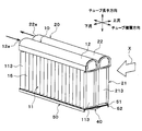
図1および図2に示すように、本実施形態の冷媒蒸発器1は、空気の流れ方向(被冷却流体の流れ方向)Xに対して直列に配置された第1蒸発部10および第2蒸発部20を備えて構成されている。本実施形態では、第1蒸発部10は、第2蒸発部20に対して、空気の流れ方向Xの下流側(風下側)に配置されている。
第1蒸発部10および第2蒸発部20の基本的構成は同一であり、それぞれ熱交換コア部11、21と、熱交換コア部11、21の上側に配置されたタンク部12、22を有して構成されている。
以下、本実施形態では、第1蒸発部10における熱交換コア部を第1コア部11と称し、第2蒸発部20における熱交換コア部を第2コア部21と称する。また、第1蒸発部10におけるタンク部を第1タンク部12と称し、第2蒸発部20におけるタンク部を第2タンク部22と称する。
第1コア部11および第2コア部21それぞれは、上下方向に延びる複数のチューブ15、25と、隣り合うチューブ15、25の間に接合されるフィン30(図3参照)とが交互に積層配置された積層体で構成されている。
以下、複数のチューブ15、25および複数のフィン30の積層体における積層方向を、チューブ積層方向と称する。また、第1コア部11を構成する複数のチューブを複数の第1チューブ15と称し、第2コア部21を構成する複数のチューブを複数の第2チューブ25と称する。また、複数の第1チューブ15および複数の第2チューブ25それぞれの長手方向を、チューブ長手方向と称する。本実施形態において、複数の第1チューブ15はそれぞれ同様の構成を有しているため、以下の説明では複数の第1チューブ15を総称して第1チューブ15と言う場合がある。また、複数の第2チューブ25はそれぞれ同様の構成を有しているため、以下の説明では複数の第2チューブ25を総称して第2チューブ25と言う場合がある。
第1チューブ15および第2チューブ25それぞれの内部には、冷媒が流れる冷媒通路が形成されている。第1チューブ15および第2チューブ25は、それぞれ、断面形状が空気の流れ方向Xに沿って延びる扁平形状となる扁平チューブで構成されている。
第1チューブ15および第2チューブ25は、空気の流れ方向Xから見たときに、互いに重合するように配置されている。以下、第1チューブ15、および、当該第1チューブ15に対して空気の流れ方向Xから見たときに重合配置される第2チューブ25を、一組のチューブ15、25と称する。冷媒蒸発器1は、複数組のチューブ15、25を有している。
一組のチューブ15、25におけるチューブ長手方向の一端側には、一組のチューブ15、25同士を連通させる中間流路40が設けられている。本実施形態では、中間流路40は、一組のチューブ15、25の下端側に配置されている。このため、第1コア部11および第2コア部21の下方側には、複数の中間流路40が設けられている。複数の中間流路40は、チューブ積層方向に並んで配置されている。なお、この中間流路40の詳細については後述する。
第1チューブ15は、チューブ長手方向の他端側(上端側)が第1タンク部12に接続されている。また、第2チューブ25は、チューブ長手方向の他端側(上端側)が第2タンク部22に接続されている。
図3に示すように、フィン30は、薄板材を波形状に折り曲げて成形したコルゲートフィンである。フィン30は、第1チューブ15と第2チューブ25における平坦な外面側に接合され、空気と冷媒との伝熱面積を拡大させるための熱交換促進部として機能する。本実施形態では、フィン30は、一組のチューブ15、25の双方に接合されている。
図1および図2に戻り、第1チューブ15、第2チューブ25およびフィン30の積層体には、チューブ積層方向の両端部に、各コア部11、22を補強するサイドプレート113、213がそれぞれ配置されている。なお、サイドプレート113、213は、チューブ積層方向の最も外側に配置されたフィン30に接合されている。
第1タンク部12は、チューブ積層方向一端側が閉塞されると共に、チューブ積層方向他端側に冷媒導入部12aが形成された筒状の部材で構成されている。冷媒導入部12aは、第1タンク部12のタンク内部に膨張弁(図示略)にて減圧された低圧冷媒を導入するものである。本実施形態では、第1タンク部12は、空気流れ上流側から見たときの左側端部が閉塞されると共に、空気流れ上流側から見たときの右側端部に冷媒導入部12aが形成されている。
第1タンク部12は、底部に各第1チューブ15のチューブ長手方向他端側(上端側)が挿入接合される貫通穴(図示略)が形成されている。第1タンク部12は、その内部空間が第1コア部11の各第1チューブ15に連通するように構成されている。第1タンク部12は、第1コア部11へ冷媒を分配する冷媒分配部として機能する。
第2タンク部22は、チューブ積層方向一端側が閉塞されると共に、チューブ積層方向他端側に冷媒導出部22aが形成された筒状の部材で構成されている。冷媒導出部22aは、第2タンク部22のタンク内部から圧縮機(図示略)の吸入側に冷媒を導出するものである。本実施形態では、第2タンク部22は、空気流れ上流側から見たときの左側端部が閉塞されると共に、空気流れ上流側から見たときの右側端部に冷媒導出部22aが形成されている。
第2タンク部22は、底部に各第2チューブ25のチューブ長手方向他端側(上端側)が挿入接合される貫通穴(図示略)が形成されている。第2タンク部22は、その内部空間が第2コア部21の各第2チューブ25に連通するように構成されている。第2タンク部22は、第2コア部21からの冷媒を集合させる冷媒集合部として機能する。
図4に示すように、第1コア部11および第2コア部21のチューブ長手方向一端側(下端側)には、複数の中間流路40を形成する流路形成部材である中間タンク部50が設けられている。中間タンク部50は、第1プレート51および第2プレート52を組み合わせることにより形成されている。
図5に示すように、第1プレート51は、略長方形の板状に形成されている。第1プレート51には、第1チューブ15および第2チューブ25それぞれのチューブ長手方向の一端部(下端部)が接合されている。具体的には、第1プレート51には、第1チューブ15におけるチューブ長手方向の一端部が挿入される第1挿入穴511と、第2チューブ25におけるチューブ長手方向の一端部が挿入される第2挿入穴512とが形成されている。第1挿入穴511および第2挿入穴512は、それぞれ、第1プレート51にバーリング加工を施すことにより形成されている。
図6に示すように、第2プレート52は、チューブ積層方向から見た断面が略U字状に形成されている。具体的には、第2プレート52は、平面部521と、2つの側面部522を有して構成されている。平面部521は、略長方形の板状に形成されるとともに、チューブ長手方向に直行する方向に伸びている。側面部522は、平面部521における空気の流れ方向Xの両端部のそれぞれから、チューブ長手方向に置いて第1コア部11および第2コア部21から離間するように延びている。平面部521および2つの側面部522は、一体に形成されている。
平面部521には、チューブ長手方向において第1コア部11および第2コア部21から離間するように突出するとともに、空気の流れ方向Xに延びる複数のリブ523が形成されている。複数のリブ523により、平面部521における第1プレート51側の面には、チューブ長手方向において第1プレート51から離間するように凹んだ複数の凹部524が形成されている。各凹部524は、一組のチューブ15、25が挿入される第1挿入穴511および第2挿入穴512と連通している。
平面部521のうち複数のリブ523が形成されていない部位は、第1プレート51に接合されている。そして、図7に示すように、第2プレート52の複数の凹部524は、第1プレート51のうち複数のリブ523と対向する面と共に、複数の中間流路40を画定している。換言すると、第2プレート52における複数のリブ523の内側面、および、第1プレート51のうち複数のリブ523と対向する面により、複数の中間流路40が構成されている。
図8に示すように、複数のリブ523はそれぞれ、空気の流れ方向Xから見た断面が略U字状に構成されている。より詳細には、複数のリブ523はそれぞれ、空気の流れ方向Xの全域にわたって、空気の流れ方向Xから見た断面が略U字状に構成されている。本実施形態では、複数のリブ523は同様の構成を有しているため、以下、複数のリブ523を総称してリブ523と言う。また、複数の中間流路40は同様の構成を有しているため、以下、複数の中間流路40を総称して中間流路40と言う。
本実施形態では、中間流路40は、チューブ積層方向の長さが一定となるように構成されている。このため、中間流路40の断面積は、中間流路40のチューブ長手方向の長さに基づいて決定される。
図7に戻り、中間流路40は、上流部41、中流部42、下流部43を有して構成されている。上流部41、中流部42および下流部43は、冷媒流れ上流側からこの順に配置されている。また、中流部42の断面積は、上流部41の断面積および下流部43の断面積の双方に対して大きい。
上流部41は、冷媒流れ下流側に向かって断面積が徐々に拡大するように構成されている。本実施形態では、上流部41は、冷媒流れ下流側に向かって断面積が直線的に拡大するように構成されている。具体的には、上流部41は、冷媒流れ下流側に向かって、チューブ長手方向の長さが徐々に長くなっている。
上流部41は、第1チューブ15のチューブ長手方向一端側(下端側)に配置されている。上流部41は、第1チューブ15と連通している。このため、上流部41には、第1チューブ15から流出した冷媒が流入する。
中流部42は、冷媒流れ下流側に向かって断面積が一定となるように構成されている。中流部42は、第1チューブ15および第2チューブ25間の隙間60に対応する位置に配置されている。中流部42は、上流部41に接続されている。このため、中流部42には、上流部41から流出した冷媒が流入する。
下流部43は、冷媒流れ下流側に向かって断面積が徐々に縮小するように構成されている。本実施形態では、下流部43は、冷媒流れ下流側に向かって断面積が直線的に縮小するように構成されている。具体的には、下流部43は、冷媒流れ下流側に向かって、チューブ長手方向の長さが徐々に短くなっている。下流部43は、第2チューブ25のチューブ長手方向一端側(下端側)に配置されている。
下流部43の冷媒流れ上流側は、中流部42に接続されている。このため、下流部43には、中流部42から流出した冷媒が流入する。また、下流部43の冷媒流れ下流側は、第2チューブ25と連通している。このため、下流部43を流れた冷媒は、第2チューブ25に流入する。
ところで、第1チューブ15は、第1チューブ15内に形成される第1冷媒流路を空気の流れ方向Xに並ぶ複数の細流路150に仕切る第1仕切部材151を有している。同様に、第2チューブ25は、第2チューブ25内に形成される第2冷媒流路を空気の流れ方向Xに並ぶ複数の細流路250に仕切る第2仕切部材251を有している。
中間流路40の中流部42の断面積は、第1チューブ15または第2チューブ25の断面積の0.3倍から3.0倍に設定されている。換言すると、中間流路40の中流部42の断面積は、第1チューブ15における複数の細流路150の断面積の合計、または、第2チューブ25における複数の細流路250の断面積の合計の0.3倍から3.0倍に設定されている。
ここで、中間流路40のうち、空気の流れ方向Xの最上流側の部位を最上流部44という。また、中間流路40のうち、空気の流れ方向Xの最下流側の部位を最下流部45という。
最上流部44および最下流部45は、中間流路40のうち断面積が最も小さくなるように構成されている。具体的には、最上流部44および最下流部45の断面積は、それぞれ、複数の細流路150および複数の細流路250のそれぞれの断面積の0.3倍~3.0倍に設定されている。換言すれば、最上流部44および最下流部45の断面積は、それぞれ、複数の細流路150のうちの1つ、または複数の細流路250のうちの1つ断面積の0.3倍~3.0倍に設定されている。
ところで、第1チューブ15における複数の細流路150は、第2チューブ25に向かって順に並ぶ、第1細流路1501から第n細流路150n(nは自然数)で構成されている。換言すれば、第1細流路1501は第2チューブ25から一番遠くに位置しており、第n細流路150nは第2チューブ25に対して一番近くに位置している。以下、中間流路40における第n細流路150nから流出直後の冷媒が流通する部位を、第n流出部46nという。
本実施形態では、第1チューブ15における複数の細流路150は、第2チューブ25に向かって順に並ぶ第1細流路1501から第7細流路1507で構成されている。このため、中間流路40には、第2チューブ25に向かって順に並ぶ第1流出部461から第7流出部467が構成されている。
ここで、本実施形態の冷媒蒸発器の製造方法について説明する。
はじめに、冷媒蒸発器の各種構成部品、すなわち第1チューブ15、第2チューブ25、フィン30、第1タンク部12、第2タンク部22、第1プレート51および第2プレート52等を製造する。以下、中間タンク部50の第1プレート51および第2プレート52の製造方法について詳細に説明する。
まず、中間タンク部50の第1プレート51を、ロール成形により形成する。具体的には、図9に示すように、帯状の第1薄板710をロール材711として用意する。このロール材711に対して、第1ロール金型712によりロール成形を施すことにより、複数の貫通穴である複数の挿入穴511、512を形成する。そして、複数の挿入穴511、512が形成された第1薄板710を、カッター713により、予め定めた基準第1長さに切断する。これにより、第1プレート51が形成される。
次に、中間タンク部50の第2プレート52を、ロール成形により形成する。具体的には、図10に示すように、帯状の第2薄板720をロール材721として用意する。このロール材721に対して、第2ロール金型722によりロール成形を施すことにより、複数のリブ523を形成する。そして、複数のリブ523が形成された第2薄板720を、カッター723により、予め定めた基準第2長さに切断する。これにより、第2プレート52が形成される。
続いて、上述のように形成された第1プレート51および第2プレート52に、複数の第1チューブ15および複数の第2チューブ25を仮固定する。さらに、このように仮固定された第1チューブ15および第2チューブ25に、フィン30、第1タンク部12および第2タンク部22を仮固定する。これにより、冷媒蒸発器の各種構成部品が仮固定された仮組み付け体が完成する。
続いて、この仮組み付け体を加熱炉内で加熱し、ろう付けする。これにより、冷媒蒸発器の各種構成部品がろう付けにより接合され、冷媒蒸発器が完成する。
以上説明したように、本実施形態では、長手方向の一方において、複数組のチューブ15、25の一端側に、複数組のチューブ15、25をそれぞれ連通させる複数の中間流路40を設けている。これによれば、複数の第1チューブ15と複数の第2チューブ25とそれぞれ対にして複数組のチューブ15、25を形成している。つまり、複数組のチューブ15、25のそれぞれに対して1つの中間流路40を設けて、1つの中間流路40によって一組のチューブ15、25を接続することができる。
このため、複数のチューブ15、25に対して冷媒の分配または集合を行う、内容積の大きい中間タンク部を廃止することができる。そして、一組のチューブ15、25の接続部である中間流路40において、一組のチューブ15、25のそれぞれの内部に形成された冷媒流路の急拡大や急縮小を抑制し、一組のチューブ15、25と中間流路40との間の冷媒流速の差を小さくすることができる。これにより、中間流路40において圧力損失が増大すること、および、複数の第2チューブ25への冷媒分配が悪化することを抑制できる。
このように、圧力損失の低減および冷媒分配の均一化を図ることで、冷媒蒸発器の熱交換効率を高効率化し、車両用空調装置の冷房能力を向上させることができる。そして、冷房能力が同一の場合、圧縮機の消費動力の低減、並びに、冷媒蒸発器の小型化および軽量化を図ることができる。
ここで、図7に示すように、第1チューブ15の第n細流路150nの断面積をSnとする。また、中間流路40における第n流出部46nの断面積をMnとする。このとき、本実施形態の中間流路40は、下記の式(1)の関係を満たすように構成されている。式(1)において、kはn以下の自然数である。

0.3S1<M1<3.0S1、
0.3(S1+S2)<M2<3.0(S1+S2)、
0.3(S1+S2+S3)<M7<3.0(S1+S2+S3)、
0.3(S1+S2+S3+S4)<M7<3.0(S1+S2+S3+S4)、
0.3(S1+S2+S3+S4+S5)<M7<3.0(S1+S2+S3+S4+S5)、
0.3(S1+S2+S3+S4+S5+S6)<M7<3.0(S1+S2+S3+S4+S5+S6)、かつ
0.3(S1+S2+S3+S4+S5+S6+S7)<M7<3.0(S1+S2+S3+S4+S5+S6+S7)
これによれば、第1チューブ15の各細流路150から中間流路40に冷媒が流出する際に冷媒流路面積が急拡大することを抑制できるので、圧力損失を低減できる。
さらに、中間流路40は、下記の式(2)の関係を満たすように構成されていることが望ましい。式(2)において、kはn以下の自然数である。

0.5S1<M1<2.0S1、
0.5(S1+S2)<M2<2.0(S1+S2)、
0.5(S1+S2+S3)<M2<2.0(S1+S2+S3)、
0.5(S1+S2+S3+S4)<M2<2.0(S1+S2+S3+S4)、
0.5(S1+S2+S3+S4+S5)<M2<2.0(S1+S2+S3+S4+S5)、
0.5(S1+S2+S3+S4+S5+S6)<M2<2.0(S1+S2+S3+S4+S5+S6)、かつ
0.5(S1+S2+S3+S4+S5+S6+S7)<M7<2.0(S1+S2+S3+S4+S5+S6+S7)
これによれば、第1チューブ15の各細流路150から中間流路40に冷媒が流出する際に冷媒流路面積が急拡大することをより抑制できるので、圧力損失をより低減できる。
ここで、複数の第1チューブ15および複数の第2チューブ25に対して冷媒の分配または集合を行う、内容積の大きい中間タンク部を備える従来の冷媒蒸発器を、比較例1の冷媒蒸発器という。
比較例1の冷媒蒸発器では、中間期や冬季等の冷房熱負荷が低く冷媒流量が少ない場合、かつ、中間タンク部を熱交換コア部の下方側に配置した場合には、中間タンク部内の内容積が大きく冷媒流速低下が著しいことにより、冷媒中に混在する冷凍機油が中間タンク部内に停滞しやすい。また、冷房熱負荷が低いことにより、中間タンク部内に冷媒が液相状態で停滞しやすい。このため、冷凍サイクルが冷凍機油不足運転や冷媒不足運転となり、冷凍機故障や性能不足に至るおそれがある。
また、中間タンク部内に気液二相状態の冷媒が存在し、各チューブ15、25を流れる冷媒の気相と液相の割合が異なることにより、複数の第1チューブ15および複数の第2チューブ25同士の間において入口と出口との圧力差が異なり、複数の第1チューブ15および複数の第2チューブ25を流れる冷媒流量に偏りが生じる。このため、冷媒分布が悪化するおそれがある。
さらに、中間タンク部内に液相冷媒が停滞すると、中間タンク部における第2チューブ25への出口部まで冷媒の液面が到達する場合がある。このとき、第2チューブ25に対して冷媒が気液混在で流出すると、冷媒流出時に異音が発生するおそれがある。
これに対し、本実施形態では、第1コア部11の第1チューブ15と第2コア部21の第2チューブ25とを内容積の小さい中間流路40により接続している。このため、冷媒流量が少ない場合でも、中間流路40に流入した液相冷媒や冷凍機油は停滞することなく第2チューブ25へ流出する。これにより、冷凍サイクルの冷媒不足運転および冷凍機油不足運転を抑制できる。
その結果、冷凍サイクルの冷媒充填量や冷凍機油封入量を低減できる。また、中間タンク部の底部において液相冷媒や冷凍機油の滞留(淀み)が抑制されるため、冷媒通過音を低減できる。
また、本実施形態のように、第1コア部11の第1チューブ15と第2コア部21の第2チューブ25とを1本ずつ中間流路40により接続することで、冷媒蒸発器の取付角度(姿勢)が垂直から傾斜した場合でも、各第2チューブ25に流入する冷媒の分配量は変化せず均一を維持できる。このため、車両用空調装置の冷房能力を維持することができる。
ここで、中間流路40を、第1プレート材、第2プレート材および第3プレート材の3枚のプレート材を重ね合わせることにより構成した従来の冷媒蒸発器を、比較例2の冷媒蒸発器という。比較例2の冷媒蒸発器は、3枚のプレート材により中間流路40を構成しているので、部品点数が増加する。
また、比較例2の冷媒蒸発器では、中間流路を形成するための第2プレート材を、平板状の金属材にプレス打ち抜き加工を施すことにより形成している。したがって、中間流路の流路面積は第2プレート材の板厚に依存することとなる。しかしながら、一般に第2プレート材の板厚は薄いため、中間流路の流路面積を大きくできず、圧力損失が増加する。また、第2プレート材の板厚を厚くして、中間流路の流路面積を大きくすることも考えられるが、第2プレート材の材料の必要量が多くなり、重量が増加したり、加工性が悪化したり、材料コストが増加したりする恐れがある。
さらに、複数のチューブおよび3枚のプレート材をろう付け接合する際には、3枚のプレート材それぞれの熱容量が大きく、接合される部材同士の熱容量や伝熱の仕方が大きく異なる。このため、ろう付け条件が厳しくなり、製造が困難となる。
これに対し、本実施形態では、中間流路40を第1プレート51および第2プレート52により構成している。このため、部品点数の増加を抑制できる。また、冷媒蒸発器を構成するために必要な材料使用量を削減できるので、軽量化を図るとともに、加工性の悪化を抑制できる。このため、材料コストおよび加工コストを低減できる。
また、中間タンク部50(第1プレート51および第2プレート52)を、熱容量が小さく偏りの少ない2枚の薄板710、720で構成することで、第1プレート51および第2プレート52をろう付けにより接合することができる。このため、中間タンク部50において、信頼性の高い気密封止をろう付けという容易な方法で行うことができる。
また、第1プレート51および第2プレート52をそれぞれロール成形にて構成することで、ロール金型712、722を使用した連続加工が可能となる。このため、中間タンク部50の生産速度を上昇させることができるので、同一時間において冷媒蒸発器を大量に生産することができる。
また、第1プレート51および第2プレート52をそれぞれロール成形にて構成することで、冷媒蒸発器に要求される冷房能力が変化した場合に、薄板710、720を、冷房能力に応じたプレート長さに切断するという簡易な方法で対応することができる。このため、設計工数や製造段取り工数を簡素化できる。
また、第2プレート52を、チューブ積層方向から見た断面がコの字状となるように形成することで、リブ効果により第2プレート52の剛性を向上させることができる。このため、第2プレート52の薄肉化を図ることができるので、冷媒蒸発器の軽量化を図ることが可能となる。
(第2実施形態)
次に、本開示の第2実施形態について図11および図12に基づいて説明する。本第2実施形態は、上記第1実施形態と比較して、チューブ15、25の形状等が異なるものである。
次に、本開示の第2実施形態について図11および図12に基づいて説明する。本第2実施形態は、上記第1実施形態と比較して、チューブ15、25の形状等が異なるものである。
図11および図12に示すように、本実施形態では、第1チューブ15の断面積が、第2チューブ25の断面積より小さい。具体的には、第1チューブ15における空気の流れ方向Xの長さが、第2チューブ25における空気の流れ方向Xの長さよりも短い。また、第1チューブ15内の細流路150の数が、第2チューブ25内の細流路250の数よりも少ない。
本実施形態によれば、第1チューブ15および第2チューブ25のうち、液相冷媒が多く流れる第1チューブ15の断面積を小さくし、気相冷媒が多く流れる第2チューブ25の断面積を大きくすることができる。このため、チューブ15、25内の冷媒流速の最大化および冷媒圧力損失量の最小化を図ることができるので、車両用空調装置の冷房性能を向上させることが可能となる。
(第3実施形態)
次に、本開示の第3実施形態について図13および図14に基づいて説明する。本第3実施形態は、上記第1実施形態と比較して、中間タンク部50の形状等が異なるものである。
次に、本開示の第3実施形態について図13および図14に基づいて説明する。本第3実施形態は、上記第1実施形態と比較して、中間タンク部50の形状等が異なるものである。
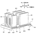
図13に示すように、本実施形態では、チューブ積層方向に並んでいる複数の中間流路40、すなわちリブ523の形状が互いに異なっている。具体的には、空気の流れ方向Xから見たときに、複数の中間流路40(複数のリブ523)は、チューブ長手方向の長さが互いに異なっている。これにより、複数の中間流路40の流路面積が互いに異なっている。
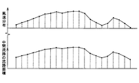
具体的には、本実施形態の中間タンク部50では、空気側熱負荷が大きい部分ほど、中間流路40の流路面積が大きい。より詳細には、図14に示すように、中間タンク部50では、空気の風速が速い部分ほど、中間流路40の流路面積が大きい。すなわち、空気の風速が速い部分ほど、中間流路40(リブ523)におけるチューブ長手方向の長さが長い。なお、複数の中間流路40(複数のリブ523)におけるチューブ積層方向の長さは、等しくなっている。
本実施形態によれば、空気側熱負荷が大きい部分における中間流路40の流路面積を大きくし、空気側熱負荷が小さい部分における中間流路40の流路面積を小さくすることができる。このため、中間流路40から各第2チューブ25の最下流側に流出する気相冷媒の過熱度を均一化することができるので、冷媒蒸発器全域で冷媒が蒸発領域となる。その結果、圧縮機へ液相冷媒が流入すること(液バック)や、過大な過熱度の気相冷媒が圧縮機へ流入することを抑制できる。このため、車両用空調装置の冷房性能を向上することができるとともに、圧縮機の消費動力を低減できる。
(第4実施形態)
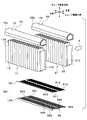
次に、本開示の第4実施形態について図15に基づいて説明する。本第4実施形態は、上記第1実施形態と比較して、第1タンク部12の形状等が異なるものである。なお、図15では、フィン30の図示を省略している。
次に、本開示の第4実施形態について図15に基づいて説明する。本第4実施形態は、上記第1実施形態と比較して、第1タンク部12の形状等が異なるものである。なお、図15では、フィン30の図示を省略している。
図15に示すように、本実施形態の第1タンク部12は、チューブ積層方向一端側(図15の紙面右側)に、冷媒導出部12bが形成されている。冷媒導出部12bは、第1タンク部12のタンク内部から圧縮機(図示略)の吸入側に冷媒を導出するものである。
第1タンク部12の内部には、第1タンク部12のタンク内空間をチューブ積層方向に2つに仕切る仕切部材120が設けられている。この仕切部材120により、第1タンク部12のタンク内空間は、第1空間121と第2空間122とに仕切られている。本実施形態では、仕切部材120は、第1タンク部12におけるチューブ積層方向の中央部よりも冷媒導入部12aに近い側に配置されている。
第1空間121は、冷媒導入部12aと連通している。冷媒導入部12aは、第1空間121に外部から冷媒を流入させる流入部を構成している。
第2空間122は、冷媒導出部12bと連通している。冷媒導出部12bは、第2空間122から外部へ冷媒を流出させる流出部を構成している。
以下、第1コア部11を構成する第1チューブ15のうち、第1空間121と連通する第1チューブ15を第1流入側チューブ15aといい、第2空間122と連通する第1チューブ15を第1流出側チューブ15bという。
また、第2コア部21を構成する第2チューブ25のうち、第1流入側チューブ15aと対向する第2チューブ25、すなわち第1流入側チューブ15aの空気流れ上流側に配置される第2チューブ25を、第2流入側チューブ25aという。第2コア部21を構成する第2チューブ25のうち、第2流出側チューブ15bと対向する第2チューブ25、すなわち第2流出側チューブ15bの空気流れ上流側に配置される第2チューブ25を、第2流出側チューブ25bという。
次に、本実施形態に係る冷媒蒸発器における冷媒の流れについて、図15を用いて説明する。
膨張弁にて減圧された低圧冷媒は、矢印aの如く、第1タンク部12のチューブ積層方向他端側に形成された冷媒導入部12aから、第1空間121に導入される。第1空間121に導入された冷媒は、矢印bの如く第1コア部11の第1流入側チューブ15aを下降する。
第1流入側チューブ15aを下降した冷媒は、矢印cの如く、中間タンク部50の中間流路40を空気流れ下流側から上流側に向かって流れ、第2コア部21の第2流入側チューブ25aに流入する。第2流入側チューブ25aに流入した冷媒は、矢印dの如く第2流入側チューブ25aを上昇し、第2タンク部22に流入する。
第2タンク部22に流入した冷媒は、矢印eの如く第2タンク部22をチューブ積層方向他端側から一端側(図15の紙面左側から右側)に向かって流れて、第2コア部21の第2流出側チューブ25bに流入する。第2流出側チューブ25bに流入した冷媒は、矢印fの如く第2流出側チューブ25bを下降し、中間タンク部50の中間流路40に流入する。
中間流路40に流入した冷媒は、矢印gの如く、中間流路40を空気流れ上流側から下流側に向かって流れ、第1コア部11の第1流出側チューブ15bに流入する。第1流出側チューブ15bに流入した冷媒は、矢印hの如く第1流出側チューブ15bを上昇して、第1タンク部12の第2空間122に流入する。第2空間122に流入した冷媒は、矢印iの如く、第1タンク部12のチューブ積層方向一端側に形成された冷媒導出部12bから圧縮機吸入側に導出される。
本実施形態によれば、第1タンク部12内に仕切部材120を設けることで、冷媒蒸発器において、冷媒流れ上流側で使用するチューブ15、25の本数を少なくし、冷媒流れ下流側で使用するチューブ15、25の本数を多くすることができる。これにより、チューブ15、25内の冷媒流速の最大化および冷媒圧力損失量の最小化を図ることができるので、車両用空調装置の冷房性能を向上させることが可能となる。
(第5実施形態)
次に、本開示の第5実施形態について図16、図17、図18、および図19に基づいて説明する。本第5実施形態は、上記第1実施形態と比較して、中間タンク部50からの排水性を向上させる構成を設けた点が異なるものである。なお、図16では、フィン30の図示を省略している。
次に、本開示の第5実施形態について図16、図17、図18、および図19に基づいて説明する。本第5実施形態は、上記第1実施形態と比較して、中間タンク部50からの排水性を向上させる構成を設けた点が異なるものである。なお、図16では、フィン30の図示を省略している。
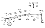
図16に示すように、第1プレート51および第2プレート52における中間流路40を構成しない部位には、第1プレート51および第2プレート52の双方を貫通する貫通穴である排水孔513、514、525、526が設けられている。
すなわち、第1プレート51には、凝縮水を排出させるための排水孔513、514が形成されている。また、第2プレート52には、凝縮水を排出させる排水孔525、526が形成されている。第2プレート52の排水孔525、526は、第1プレート51の排水孔513、514と対応する部位に配置されている。
このため、コア部11、21で生じた凝縮水は、チューブ15、25またはフィン30を伝って下降し、排水孔513、514、525、526を介して冷媒蒸発器の下方側に排出される。
具体的には、図17に示すように、第1プレート51における隣り合う第1挿入穴511の間に、第1排水孔513が設けられている。また、第1プレート51における隣り合う第2挿入穴512の間に、第2排水孔514が設けられている。第1排水孔513および第2排水孔514は、第1プレート51の表裏を貫通する貫通穴である。
本実施形態では、第1排水孔513および第2排水孔514は、三角形状に形成されている。具体的には、第1排水孔513は、空気流れ下流側に底辺を有する二等辺三角形状に形成されている。第2排水孔514は、空気流れ上流側に底辺を有する二等辺三角形状に形成されている。
図18に示すように、第2プレート52における隣り合うリブ523の間に、第3排水孔525および第4排水孔526が設けられている。第3排水孔525および第4排水孔526は、空気の流れ方向Xに並んで配置されている。第3排水孔525は、第4排水孔526よりも空気流れ下流側に配置されている。第3排水孔525および第4排水孔526は、第2プレート52の表裏を貫通する貫通穴である。
第3排水孔525は、第1プレート51の第1排水孔513と対応する部位に配置されている。チューブ長手方向から見たときに、第3排水孔525は、第1排水孔513と同様の形状に形成されている。すなわち、第3排水孔525は、空気流れ下流側に底辺を有する二等辺三角形状に形成されている。
第4排水孔526は、第1プレート51の第2排水孔514と対応する部位に配置されている。チューブ長手方向から見たときに、第4排水孔526は、第2排水孔514と同様の形状に形成されている。すなわち、第4排水孔526は、空気流れ上流側に底辺を有する二等辺三角形状に形成されている。
図19に示すように、第3排水孔525の外周縁部には、下方側に向けて切り起こされた切り起こし部527が設けられている。この切り起こし部527は、第3排水孔525をロール成形により形成する際に切り起こされた部分である。本実施形態では、二等辺三角形状の第3排水孔525の2つの等辺に、切り起こし部527がそれぞれ接続されている。なお、図示を省略しているが、第4排水孔526の外周縁部にも、同様の切り起こし部527が設けられている。
本実施形態によれば、第1プレート51および第2プレート52に排水孔513、514、525、526を設けることで、コア部11、21で生じた凝縮水を、排水孔513、514、525、526を介して排出することができる。
このとき、第1プレート51および第2プレート52は、ローラ成形(圧延プレス加工)により生産されているので、微細加工を行うことが可能である。このため、本実施形態のように、第1プレート51および第2プレート52に対して、挿入穴511、512およびリブ523に加えて排水孔513、514、525、526を形成することが可能となる。
さらに、本実施形態では、第2プレート52の排水孔525、526の外周縁部に、切り起こし部527を設けている。これにより、排水孔525、526から滴下する水滴の水切れ性を向上させることができる。
(第6実施形態)
次に、本開示の第6実施形態について図20および図21に基づいて説明する。本第6実施形態は、上記第5実施形態と比較して、中間タンク部50の形状が異なるものである。
次に、本開示の第6実施形態について図20および図21に基づいて説明する。本第6実施形態は、上記第5実施形態と比較して、中間タンク部50の形状が異なるものである。
図20および図21に示すように、本実施形態の第1プレート51は、平坦面515および傾斜面516を有して構成されている。平坦面515は、チューブ長手方向に直行する、すなわち水平方向に延びる面である。平坦面515には、第2挿入穴512が形成されている。
傾斜面516は、空気流れ下流側に向かって徐々に下方に傾斜している。傾斜面516には、第1挿入穴511が形成されている。傾斜面516は、平坦面515の空気流れ下流側に接続されている。また、平坦面515および傾斜面516は、一体に形成されている。
本実施形態によれば、第1プレート51の空気流れ下流側に、空気流れ下流側に向かって徐々に下方に傾斜した傾斜面516を設けているので、凝縮水の排水性をより向上させることができる。
(他の実施形態)
本開示は上述の実施形態に限定されることなく、本開示の趣旨を逸脱しない範囲内で、例えば以下のように種々変形可能である。また、上記各実施形態に開示された技術的特徴は、実施可能な範囲で適宜組み合わせてもよい。
本開示は上述の実施形態に限定されることなく、本開示の趣旨を逸脱しない範囲内で、例えば以下のように種々変形可能である。また、上記各実施形態に開示された技術的特徴は、実施可能な範囲で適宜組み合わせてもよい。
(1)上記実施形態では、中間タンク部50を、コア部11、21のチューブ長手方向一端側(下端側)に配置した例について説明したが、中間タンク部50の配置はこれに限定されない。例えば、中間タンク部50を、コア部11、21のチューブ長手方向他端側(上端側)に配置してもよい。
(2)上記実施形態では、リブ523を、空気の流れ方向Xから見た断面が略U字状に構成した例について説明したが、リブ523の形状はこれに限定されない。例えば、図22に示すように、リブ523を、空気の流れ方向Xから見た断面が略V字状に構成してもよい。
(3)上記実施形態では、フィン30を、一組のチューブ15、25の双方に接合した例について説明したが、フィン30の配置はこれに限定されない。例えば、チューブ積層方向に隣り合う第1チューブ15同士に接合されるフィン30と、チューブ積層方向に隣り合う第2チューブ25同士に接合されるフィン30とを別体として設けてもよい。
(4)上記第3実施形態では、中間タンク部50を、空気の風速分布に応じて中間流路40の流路面積が変化するように構成した例について説明したが、中間タンク部50の構成はこれに限定されない。
例えば、中間タンク部50を、空気の温度分布(湿度分布)に応じて中間流路40の流路面積が変化するように構成してもよい。具体的には、空気の温度(湿度)が高い部位ほど、中間流路40の流路面積を大きくしてもよい。
(5)上記第5、6実施形態では、第2プレート52の第3排水孔525および第4排水孔526の外周縁部に、切り起こし部527をそれぞれ設けた例について説明したが、第3排水孔525および第4排水孔526の構成はこれに限定されない。例えば、第3排水孔525および第4排水孔526の外周縁部に、切り起こし部527を設けなくてもよい。
Claims (14)
- 被冷却流体と冷媒との間で熱交換を行う冷媒蒸発器であって、
前記被冷却流体が内部を流れ方向に通過するように構成された第1蒸発部(10)と、
前記被冷却流体が内部を前記流れ方向に通過するように構成されると共に、前記流れ方向において前記第1蒸発部と直列に配置された第2蒸発部(20)と、
前記流れ方向と垂直なチューブ長手方向に延伸すると共に前記流れ方向および前記チューブ長手方向の双方に垂直なチューブ積層方向に積層されて前記冷媒が内部を流通する複数の第1チューブ(15)を含み、前記第1蒸発部を構成する第1コア部(11)と、
前記チューブ長手方向に延伸すると共に前記チューブ積層方向に積層されて前記冷媒が内部を流通する複数の第2チューブ(25)を含み、前記第2蒸発部を構成する第2コア部(21)と、
前記チューブ長手方向の一方において、前記第1コア部の一端部および前記第2コア部の一端部に接続されると共に、前記複数の第1チューブの一端部および前記複数の第2チューブの一端部を収容する第1プレート(51)と、
前記チューブ長手方向において前記第1プレートを挟んで前記第1コア部および前記第2コア部と対向すると共に、前記第1プレートに接合された第2プレート(52)と、を備え、
前記第2プレートは、前記チューブ長手方向において前記第1コア部および前記第2コア部から離間するように突出するとともに前記流れ方向に延びる複数のリブ(523)を有し、
前記複数のリブは、前記第1プレートとともに、その内部に複数の中間流路(40)を画定し、
前記複数の第1チューブおよび前記複数の第2チューブは、前記流れ方向から見たときに互いに重合するように配置されて、前記流れ方向に対向する1つの第1チューブおよび1つの第2チューブからなる一組のチューブを複数組形成し、
前記複数の中間流路が、前記複数組のチューブを連通させる冷媒蒸発器。 - 前記複数の中間流路は、前記複数の第1チューブから流出した前記冷媒を前記複数の第2チューブに流入させるように構成されており、
前記複数の第1チューブのそれぞれが、その内部に冷媒流路を形成しており、
前記冷媒流路は、複数の細流路(150)に分割されており、
前記複数の細流路は、前記流れ方向に並んで配置されており、
前記複数の細流路は、前記複数の第2チューブからに向かって順に並ぶ第1細流路から第n細流路(nは自然数)で構成されており、
前記第n細流路の断面積をSnとし、
前記複数の中間流路のそれぞれにおける前記第n細流路から流出直後の冷媒が流通する部位の断面積をMnとしたとき、
前記複数の中間流路のそれぞれは、下記の式(1)の関係を満たすように構成されており、
前記式(1)において、kはn以下の自然数である請求項1に記載の冷媒蒸発器。

- 前記複数の中間流路はそれぞれ、下記の式(2)の関係を満たすように構成されており、
前記式(2)において、kはn以下の自然数である請求項2に記載の冷媒蒸発器。

- 前記第1蒸発部は、前記第2蒸発部に対して前記流れ方向の下流側に配置されており、
前記複数の中間流路は、前記複数の第1チューブから流出した前記冷媒を前記複数の第2チューブに流入させるように構成されており、
前記複数の第1チューブのそれぞれは、その内部に第1冷媒流路を形成し、
前記複数の第2チューブのそれぞれは、その内部に第2冷媒流路を形成しており、
前記第1冷媒流路は、前記流れ方向に並ぶ複数の細流路(150)に分割されており、
前記第2冷媒流路は、前記流れ方向に並ぶ複数の細流路(250)に分割されており、
前記複数の中間流路それぞれのうち、前記流れ方向の最下流側の部位(44)における断面積は、前記複数の第1チューブのうち対応する1つの第1チューブに形成された前記複数の細流路(150)の断面積の合計または前記複数の第2チューブのうち対応する1つの第2チューブに形成された前記複数の細流路(250)の断面積の合計の0.3倍から3.0倍に設定されている請求項1ないし3のいずれか1つに記載の冷媒蒸発器。 - 前記第1蒸発部は、前記第2蒸発部に対して前記流れ方向の下流側に配置されており、
前記複数の中間流路は、前記複数の第1チューブから流出した前記冷媒を前記複数の第2チューブに流入させるように構成されており、
前記複数の第1チューブのそれぞれは、その内部に第1冷媒流路を形成しており、
前記複数の第2チューブのそれぞれは、その内部に第2冷媒流路を形成しており、
前記第1冷媒流路は、前記流れ方向に並ぶ複数の細流路(150)に分割されており、
前記第2冷媒流路は、前記流れ方向に並ぶ複数の細流路(250)に分割されており、
前記複数の中間流路それぞれのうち、前記流れ方向の最上流側の部位(45)における断面積は、前記第1冷媒流路内の前記複数の細流路(150)および前記第2冷媒流路内の前記複数の細流路(250)のそれぞれの断面積の0.3倍から3.0倍に設定されている請求項1ないし4のいずれか1つに記載の冷媒蒸発器。 - 前記複数の中間流路はそれぞれ、前記流れ方向から見た断面形状がU字状またはV字状である請求項1ないし5のいずれか1つに記載の冷媒蒸発器。
- 前記複数の中間流路は、前記複数組のチューブの下方側にそれぞれ配置されている請求項1ないし6のいずれか1つに記載の冷媒蒸発器。
- 前記複数の中間流路は、前記複数の第1チューブから流出した前記冷媒を前記複数の第2チューブに流入させるように構成されており、
前記第1蒸発部は、前記第2蒸発部に対して前記流れ方向の下流側に配置されており、
前記複数の第1チューブそれぞれの断面積は、前記複数の第2チューブそれぞれの断面積よりも小さい請求項1ないし7のいずれか1つに記載の冷媒蒸発器。 - 前記複数の中間流路のうち少なくとも1つの中間流路の断面積は、前記複数の中間流路のうち他の中間流路の断面積と異なる請求項1ないし8のいずれか1つに記載の冷媒蒸発器。
- 前記第1蒸発部は、前記複数の第1チューブにおける前記チューブ長手方向の他端部に接続されるとともに、前記複数の第1チューブに対して前記冷媒の集合あるいは分配を行う第1タンク部(12)を有しており、
前記第2蒸発部は、前記複数の第2チューブのチューブ長手方向他端部に接続されるとともに、前記複数の第2チューブに対して前記冷媒の集合あるいは分配を行う第2タンク部(22)を有しており、
前記第1タンク部には、
当該第1タンク部内の空間を前記複数の第1チューブの積層方向に並ぶ第1空間(121)および第2空間(122)に仕切る仕切部材(120)と、
前記第1空間に外部から前記冷媒を流入させる流入部(12a)と、
前記第2空間から外部へ前記冷媒を流出させる流出部(12b)と、が設けられている請求項1ないし9のいずれか1つに記載の冷媒蒸発器。 - 前記複数の中間流路は、前記複数組のチューブの下方側にそれぞれ配置されており、
前記第1プレートおよび前記第2プレートのうち前記複数の中間流路を構成しない部位には、前記第1プレートおよび前記第2プレートの双方を貫通する貫通穴(513、514、525、526)が設けられている請求項1ないし10のいずれか1つに記載の冷媒蒸発器。 - 前記貫通穴の外周縁部には、前記第2プレートから下方側に向かって切り起こされた切り起こし部(527)が接続されている請求項11に記載の冷媒蒸発器。
- 前記第1プレートにおける前記流れ方向の下流側には、前記流れ方向の下流側に向かって下方側に傾斜した傾斜面(516)が設けられている請求項1ないし12のいずれか1つに記載の冷媒蒸発器。
- 請求項1ないし13のいずれか1つに記載の冷媒蒸発器の製造方法であって、
帯状の第1薄板(710)に対して、第1ロール金型(712)によりロール成形を施すことにより、前記複数の第1チューブおよび前記複数の第2チューブを挿入するための複数の貫通穴(511、512)を形成する工程と、
前記貫通穴が形成された前記第1薄板を予め定めた基準第1長さに切断することにより、前記第1プレートを形成する工程と、
帯状の第2薄板(720)に対して、第2ロール金型(722)によりロール成形を施すことにより、前記複数のリブを形成する工程と、
前記複数のリブが形成された前記第2薄板を予め定めた基準第2長さに切断することにより、前記第2プレートを形成する工程と、
前記複数の第1チューブおよび前記複数の第2チューブを、前記第1プレートおよび前記第2プレートに仮固定する工程と、
前記複数の第1チューブ、前記複数の第2チューブ、前記第1プレートおよび前記第2プレートを仮固定した仮組み付け体を加熱炉内で加熱し、ろう付けする工程と、を備える冷媒蒸発器の製造方法。
Priority Applications (3)
| Application Number | Priority Date | Filing Date | Title |
|---|---|---|---|
| DE112018002406.7T DE112018002406T5 (de) | 2017-05-10 | 2018-04-16 | Kältemittelverdampfer und Verfahren zu dessen Herstellung |
| CN201880031072.9A CN110651162B (zh) | 2017-05-10 | 2018-04-16 | 制冷剂蒸发器及其制造方法 |
| US16/654,086 US11346584B2 (en) | 2017-05-10 | 2019-10-16 | Refrigerant evaporator and method for manufacturing same |
Applications Claiming Priority (2)
| Application Number | Priority Date | Filing Date | Title |
|---|---|---|---|
| JP2017094153A JP6717256B2 (ja) | 2017-05-10 | 2017-05-10 | 冷媒蒸発器およびその製造方法 |
| JP2017-094153 | 2017-05-10 |
Related Child Applications (1)
| Application Number | Title | Priority Date | Filing Date |
|---|---|---|---|
| US16/654,086 Continuation US11346584B2 (en) | 2017-05-10 | 2019-10-16 | Refrigerant evaporator and method for manufacturing same |
Publications (1)
| Publication Number | Publication Date |
|---|---|
| WO2018207556A1 true WO2018207556A1 (ja) | 2018-11-15 |
Family
ID=64104456
Family Applications (1)
| Application Number | Title | Priority Date | Filing Date |
|---|---|---|---|
| PCT/JP2018/015659 WO2018207556A1 (ja) | 2017-05-10 | 2018-04-16 | 冷媒蒸発器およびその製造方法 |
Country Status (5)
| Country | Link |
|---|---|
| US (1) | US11346584B2 (ja) |
| JP (1) | JP6717256B2 (ja) |
| CN (1) | CN110651162B (ja) |
| DE (1) | DE112018002406T5 (ja) |
| WO (1) | WO2018207556A1 (ja) |
Cited By (1)
| Publication number | Priority date | Publication date | Assignee | Title |
|---|---|---|---|---|
| CN112240714A (zh) * | 2019-07-19 | 2021-01-19 | 广州汽车集团股份有限公司 | 一种蒸发器 |
Families Citing this family (1)
| Publication number | Priority date | Publication date | Assignee | Title |
|---|---|---|---|---|
| KR20230089605A (ko) * | 2021-12-13 | 2023-06-21 | 삼성전자주식회사 | 열 교환기 및 이를 포함하는 열 교환 시스템 |
Citations (10)
| Publication number | Priority date | Publication date | Assignee | Title |
|---|---|---|---|---|
| JP2004053132A (ja) * | 2002-07-19 | 2004-02-19 | Denso Corp | 冷却器 |
| JP2004163036A (ja) * | 2002-11-14 | 2004-06-10 | Japan Climate Systems Corp | 複列型熱交換器 |
| JP2007057176A (ja) * | 2005-08-25 | 2007-03-08 | Calsonic Kansei Corp | 熱交換器 |
| JP2008025956A (ja) * | 2006-07-25 | 2008-02-07 | Showa Denko Kk | 熱交換器 |
| JP2009014282A (ja) * | 2007-07-05 | 2009-01-22 | Japan Climate Systems Corp | 熱交換器 |
| JP2009275956A (ja) * | 2008-05-13 | 2009-11-26 | Denso Corp | 熱交換器 |
| JP2011214827A (ja) * | 2010-03-31 | 2011-10-27 | Modine Manufacturing Co | 熱交換器 |
| WO2011161918A1 (ja) * | 2010-06-25 | 2011-12-29 | 株式会社デンソー | 熱交換器 |
| JP2015152209A (ja) * | 2014-02-13 | 2015-08-24 | パナソニックIpマネジメント株式会社 | 熱交換器 |
| WO2015189990A1 (ja) * | 2014-06-13 | 2015-12-17 | 三菱電機株式会社 | 熱交換器 |
Family Cites Families (12)
| Publication number | Priority date | Publication date | Assignee | Title |
|---|---|---|---|---|
| DE9400687U1 (de) * | 1994-01-17 | 1995-05-18 | Thermal Waerme Kaelte Klima | Verdampfer für Klimaanlagen in Kraftfahrzeugen mit Mehrkammerflachrohren |
| TW552382B (en) * | 2001-06-18 | 2003-09-11 | Showa Dendo Kk | Evaporator, manufacturing method of the same, header for evaporator and refrigeration system |
| JP4121085B2 (ja) | 2001-12-21 | 2008-07-16 | ベール ゲーエムベーハー ウント コー カーゲー | 特に自動車用の熱交換器 |
| JP4124136B2 (ja) | 2003-04-21 | 2008-07-23 | 株式会社デンソー | 冷媒蒸発器 |
| JP4193741B2 (ja) * | 2004-03-30 | 2008-12-10 | 株式会社デンソー | 冷媒蒸発器 |
| JP2008116102A (ja) * | 2006-11-02 | 2008-05-22 | Denso Corp | 冷却用熱交換器 |
| JP5136050B2 (ja) * | 2007-12-27 | 2013-02-06 | 株式会社デンソー | 熱交換器 |
| CN103338738B (zh) | 2011-01-31 | 2017-08-29 | Ea制药株式会社 | 多室容器 |
| JP5796564B2 (ja) * | 2011-11-30 | 2015-10-21 | 株式会社デンソー | 熱交換器 |
| JP6050978B2 (ja) * | 2012-07-23 | 2016-12-21 | 株式会社ケーヒン・サーマル・テクノロジー | エバポレータ |
| EP3064880B1 (en) * | 2013-10-30 | 2021-03-24 | Mitsubishi Electric Corporation | Laminated header, heat exchanger, and air-conditioning apparatus |
| JP6341099B2 (ja) | 2015-01-14 | 2018-06-13 | 株式会社デンソー | 冷媒蒸発器 |
-
2017
- 2017-05-10 JP JP2017094153A patent/JP6717256B2/ja active Active
-
2018
- 2018-04-16 CN CN201880031072.9A patent/CN110651162B/zh active Active
- 2018-04-16 WO PCT/JP2018/015659 patent/WO2018207556A1/ja active Application Filing
- 2018-04-16 DE DE112018002406.7T patent/DE112018002406T5/de not_active Withdrawn
-
2019
- 2019-10-16 US US16/654,086 patent/US11346584B2/en active Active
Patent Citations (10)
| Publication number | Priority date | Publication date | Assignee | Title |
|---|---|---|---|---|
| JP2004053132A (ja) * | 2002-07-19 | 2004-02-19 | Denso Corp | 冷却器 |
| JP2004163036A (ja) * | 2002-11-14 | 2004-06-10 | Japan Climate Systems Corp | 複列型熱交換器 |
| JP2007057176A (ja) * | 2005-08-25 | 2007-03-08 | Calsonic Kansei Corp | 熱交換器 |
| JP2008025956A (ja) * | 2006-07-25 | 2008-02-07 | Showa Denko Kk | 熱交換器 |
| JP2009014282A (ja) * | 2007-07-05 | 2009-01-22 | Japan Climate Systems Corp | 熱交換器 |
| JP2009275956A (ja) * | 2008-05-13 | 2009-11-26 | Denso Corp | 熱交換器 |
| JP2011214827A (ja) * | 2010-03-31 | 2011-10-27 | Modine Manufacturing Co | 熱交換器 |
| WO2011161918A1 (ja) * | 2010-06-25 | 2011-12-29 | 株式会社デンソー | 熱交換器 |
| JP2015152209A (ja) * | 2014-02-13 | 2015-08-24 | パナソニックIpマネジメント株式会社 | 熱交換器 |
| WO2015189990A1 (ja) * | 2014-06-13 | 2015-12-17 | 三菱電機株式会社 | 熱交換器 |
Cited By (1)
| Publication number | Priority date | Publication date | Assignee | Title |
|---|---|---|---|---|
| CN112240714A (zh) * | 2019-07-19 | 2021-01-19 | 广州汽车集团股份有限公司 | 一种蒸发器 |
Also Published As
| Publication number | Publication date |
|---|---|
| DE112018002406T5 (de) | 2020-01-23 |
| JP2018189337A (ja) | 2018-11-29 |
| CN110651162A (zh) | 2020-01-03 |
| CN110651162B (zh) | 2021-12-07 |
| JP6717256B2 (ja) | 2020-07-01 |
| US20200049382A1 (en) | 2020-02-13 |
| US11346584B2 (en) | 2022-05-31 |
Similar Documents
| Publication | Publication Date | Title |
|---|---|---|
| EP2097707A1 (en) | Heat exchanger design for improved performance and manufacturability | |
| WO2014041771A1 (ja) | 熱交換器 | |
| US9797656B2 (en) | Vehicle interior heat exchanger and inter-header connecting member of vehicle interior heat exchanger | |
| JP6341099B2 (ja) | 冷媒蒸発器 | |
| WO2014188689A1 (ja) | 冷媒蒸発器 | |
| WO2018207556A1 (ja) | 冷媒蒸発器およびその製造方法 | |
| JP6842915B2 (ja) | エバポレータ | |
| WO2014068842A1 (ja) | 冷媒蒸発器 | |
| JP2013024517A (ja) | 積層型熱交換器 | |
| JP6558269B2 (ja) | 冷媒蒸発器 | |
| JP6558268B2 (ja) | 冷媒蒸発器 | |
| JP6322982B2 (ja) | 冷媒蒸発器 | |
| JPWO2006129598A1 (ja) | 熱交換器 | |
| JP2010107131A (ja) | 冷媒蒸発器 | |
| WO2014181547A1 (ja) | 冷媒蒸発器 | |
| JP2008256234A (ja) | エバポレータ | |
| JPH03247992A (ja) | 積層型熱交換器 | |
| JP2007178017A (ja) | 熱交換器 | |
| JP6613996B2 (ja) | 冷媒蒸発器 | |
| US20200217589A1 (en) | Tube assembly for heat management apparatus and method of manufacturing the same | |
| JP2006284163A (ja) | 一体型熱交換装置 | |
| JP6432275B2 (ja) | 冷媒蒸発器 | |
| JP2017190896A (ja) | 熱交換器 | |
| WO2006033371A1 (en) | Integrated heat exchange apparatus | |
| KR20170011736A (ko) | 열교환기용 튜브 |
Legal Events
| Date | Code | Title | Description |
|---|---|---|---|
| 121 | Ep: the epo has been informed by wipo that ep was designated in this application |
Ref document number: 18798503 Country of ref document: EP Kind code of ref document: A1 |
|
| 122 | Ep: pct application non-entry in european phase |
Ref document number: 18798503 Country of ref document: EP Kind code of ref document: A1 |