WO2018199261A1 - 蓋 - Google Patents
蓋 Download PDFInfo
- Publication number
- WO2018199261A1 WO2018199261A1 PCT/JP2018/017068 JP2018017068W WO2018199261A1 WO 2018199261 A1 WO2018199261 A1 WO 2018199261A1 JP 2018017068 W JP2018017068 W JP 2018017068W WO 2018199261 A1 WO2018199261 A1 WO 2018199261A1
- Authority
- WO
- WIPO (PCT)
- Prior art keywords
- resin
- resin sheet
- molds
- molded body
- corner
- Prior art date
- Legal status (The legal status is an assumption and is not a legal conclusion. Google has not performed a legal analysis and makes no representation as to the accuracy of the status listed.)
- Ceased
Links
Images




























Classifications
-
- A—HUMAN NECESSITIES
- A47—FURNITURE; DOMESTIC ARTICLES OR APPLIANCES; COFFEE MILLS; SPICE MILLS; SUCTION CLEANERS IN GENERAL
- A47K—SANITARY EQUIPMENT; ACCESSORIES THEREFOR, e.g. TOILET ACCESSORIES
- A47K3/00—Baths; Showers; Appurtenances therefor
Definitions
- the present invention relates to a lid that covers an opening.
- an edge protector is attached to the peripheral edge of the lid body, and the edge protector is in contact with the upper surface of the flange portion of the bathtub.
- a synthetic resin tube body that can be freely deformed according to the shape of the upper surface is formed, and the synthetic resin tube body is brought into contact with the upper surface of the flange portion of the bathtub when the lid is applied.
- a bathtub lid is disclosed.
- the lid disclosed in Patent Document 1 can prevent a gap from being formed between the lid body and the bathtub body while the peripheral edge of the lid body is protected.
- providing a synthetic resin tube body that can be freely deformed corresponding to the shape of the upper surface of the bathtub increases the man-hours for manufacturing.
- the present invention has been made in view of such circumstances, is easy to manufacture, and can reduce the occurrence of a gap between the lid and the mounting surface while appropriately protecting the corner of the lid.
- a lid is provided.
- a lid that covers an opening, comprising a main body and a corner material that protects a corner of the main body, wherein the main body and the corner material are formed of different materials.
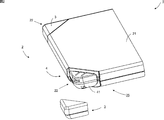
- the lid 1 includes a main body 2 and a corner material 3 that protects a corner 22 of the main body 2.
- the main body 2 and the corner material 3 are formed of different materials. Thereby, the corner 22 of the main body 2 can be appropriately protected by the corner material 3, and the sliding of the lid 1 with the placement surface due to the frictional force between the corner material 3 and the placement surface can be reduced.
- the corner material is formed of an elastomer.
- the bottom surface of the main body and the bottom surface of the corner member are configured to be flush with each other when the lid is placed.
- the main body includes a base portion and an attachment portion protruding from the base portion, and the corner material is attached to the attachment portion.
- the attachment portion includes a protrusion protruding in the thickness direction of the main body.
- the corner member is configured to be deformed by the protrusion when mounted on the attachment portion.
- the protrusion is provided on an arm provided on the main body.
- the attachment portion includes a protrusion portion protruding from the base portion and an attachment member attached to the protrusion portion, and the protrusion is provided on the attachment member.
- the attachment member is attached to the protrusion so as to accommodate at least a part of the protrusion.
- the corner member accommodates at least a part of the attachment member and is mounted so that an end surface thereof is in contact with the base portion.
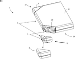
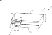
- FIG. 1 is a perspective view of a lid 1 according to the first embodiment of the present invention. It is a perspective view showing the state which removed the corner material 3 from FIG. 2, and represents the state which attached the attachment member 41 to the base
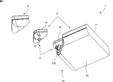
- FIG. FIG. 4 is a view corresponding to FIG. 3, and is an exploded perspective view seen from below the main body 2, the corner material 3, and the attachment portion 4 (projection portion 23 + attachment member 41) constituting the lid 1.
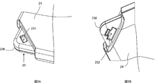
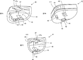
- 5A and 5B are a top perspective view and a bottom perspective view around the protrusion 23.
- FIG. 2 is a perspective view of a main body 2.
- 7A and 7B are perspective views of the attachment member 41
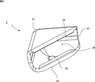
- FIG. 7C is a cross section passing through the middle point of the upper slit 47. It is the figure which looked at the attachment member 41 from the direction of the arrow X of FIG. 3 is a perspective view of a corner material 3.
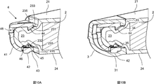
- FIG. 10A is a cross-sectional perspective view showing a state in which the attachment member 41 is mounted on the protrusion 23.
- FIG. 10B is a cross-sectional perspective view showing a state in which the corner member 3 is attached to the attachment member 41. It is sectional drawing which looked at the plane Z of FIG. 1 from the UL direction in the state which attached the attachment member 41 and the corner material 3 to the base 21.
- FIG. 12 is a view corresponding to FIG. 11, and is a cross-sectional view of the main body 2 placed on the placement surface 10. It is the elements on larger scale of the area
- region X1 of FIG. FIG. 16 is a cross-sectional view taken along line AA of FIG. It is the elements on larger scale of the area
- the hatching of the spacer member 130 is omitted, and the outer edge thereof is illustrated by a dotted line.
- FIG. 4 is a perspective view of a spacer member 130 used for manufacturing the structure 150.
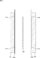
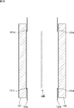
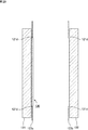
- FIG. It is the elements on larger scale which looked at the area
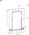
- FIG. 2 is a perspective view of a first mold 121.
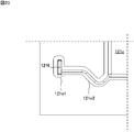
- FIG. It is an enlarged view of the periphery of the discarded bag forming part 121e1s.
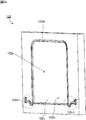
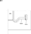
- FIG. 5 is a perspective view of a second mold 122. It is an enlarged view around the discarded bag forming part 122e1.
- FIG. 3 It is sectional drawing seen from the other direction of the 1st and 2nd metal mold
- FIG. It is the elements on larger scale of the area
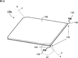
- FIG. 33 is a sectional view taken along line AA in FIG. 32.
- region Y2 of FIG. 16 is a partially enlarged view of the vicinity of the notch 132 in the BB cross-sectional view of FIG. FIG.
- FIG. 21 is a conceptual diagram virtually illustrating a planar resin molded body 140 passing through a hole 141 in a partially enlarged view of a region Z2 in FIG. 20. It is a partially cutaway perspective view of a resin panel 330 according to a third embodiment of the present invention. It is a figure which shows an example of the molding machine 1 which can be utilized with the manufacturing method of the resin panels 330. It is an enlarged view of the vicinity of the 1st and 2nd metal mold
- FIG. 331 It is a bottom perspective view of foam 331 concerning a 3rd embodiment of the present invention. It is a side view of the foam 31 seen from the arrow Y direction of FIG. It is the elements on larger scale of the area
- FIG. It is a top view showing the modification 1 of the foam 331.
- FIG. It is a top view showing the modification 2 of the foam 331.
- FIG. It is a perspective view of the resin molding 401 of one Embodiment of this invention.
- It is a block diagram (The longitudinal cross-sectional view about the metal mold
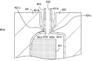
- 57A is an enlarged cross-sectional view of the vicinity of the upper ends of the molds 421 and 431 in FIG. 56, and FIG.
- FIG. 57B is a cross-sectional view showing a state in which the molds 421 and 431 are brought into contact with the state of FIG. 57A. It is sectional drawing which shows the state which inject
- FIG. 59 is a cross-sectional view showing a state after the resin sheet 423 is shaped along the cavity inner surface of the mold 421 from the state of FIG. 59 is a cross-sectional view showing a state after the insert member 407 is attached to the resin sheet 423 and the resin sheet 433 is injected between the molds 421 and 431 from the state of FIG.
- FIG. 61 is a cross-sectional view showing a state after the resin sheet 433 is shaped along the cavity inner surface of the mold 431 from the state of FIG. 60.
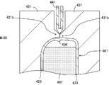
- FIG. 57B is an enlarged cross-sectional view corresponding to FIG. 57A, showing a state immediately before mold clamping, in which the molds 421 and 431 are brought close to the state of FIG. 61.
- FIG. 62 is a cross-sectional view showing a state after the molds 421 and 431 are clamped from the state of FIG. 61.
- FIG. 63 is an enlarged cross-sectional view in the vicinity of the upper ends of molds 421 and 431 in FIG. 62. It is sectional drawing of the state which took out the resin molding 401 from the state of FIG. FIG.
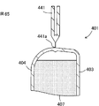
- FIG. 66 is a cross-sectional view of the state after the burr 441 is removed from the state of FIG.
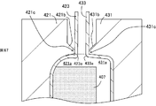
- FIG. 62B is a cross-sectional view corresponding to FIG. 62A when molding is performed using the mold of the reference example.
- FIG. 68 is a cross-sectional view showing a state after the molds 421 and 431 are clamped from the state of FIG. 67.
- FIG. 69 is a cross-sectional view of a state where a resin molded body 401 is taken out from the state of FIG.
- FIG. 70 is a cross-sectional view of the state after the burr 441 is removed from the state of FIG. 69.
- the lid 1 which concerns on this embodiment is a lid
- the lid 1 includes a main body 2 and a corner member 3 that protects a corner 22 of the main body 2.
- a general bath lid may be warped due to a temperature difference between a bath temperature (inner side of the bath lid) and a bathroom temperature (outer side of the bath lid). Such warpage is particularly likely to occur at corners. And with the curvature of a bath lid, a clearance gap will arise in the mounting surface of a bath lid and a bathtub, and the temperature of a bathtub will fall.
- cover 1 which concerns on this embodiment makes it one of the objectives to reduce that a clearance gap produces between a lid
- the main body 2 includes a base body 25 and a mounting member 41.
- the material and shape of the main body 2 are not particularly limited, and can be any material and shape according to the bathtub.
- the main body 2 is preferably a resin molded body, and more preferably a vacuum molded body.
- the raw material resin constituting the main body 2 is a thermoplastic resin such as polyolefin, for example.
- the polyolefin include low density polyethylene, linear low density polyethylene, high density polyethylene, polypropylene, and ethylene-propylene copolymer. And coalesced and mixtures thereof. Moreover, you may contain an additive.
- the additive examples include inorganic fillers such as silica, mica, talc, calcium carbonate, glass fiber, and carbon fiber, plasticizers, stabilizers, colorants, antistatic agents, flame retardants, and foaming agents.
- silica, mica, glass fiber or the like is added in an amount of 50 wt% or less, preferably 30 to 40 wt% with respect to the molding resin.
- the base body 25 includes a base portion 21 and a protruding portion 23. Further, as shown in FIGS. 11 to 14, the base body 25 is a hollow body, and the foam material 5 is inserted therein.
- the material of the foam material 5 is not particularly limited, but is preferably the same material as the base body 25. This is because heat welding occurs when the base 25 and the foam material 5 are made of the same material, and the two members can be bonded without using a solvent or the like.
- the expansion ratio of the foam material 5 is 10 to 30 times, preferably 15 to 20%. In addition, the expansion ratio of the foam material 5 is not limited to these, and can be appropriately selected in consideration of rigidity and heat insulation.
- the foam material 5 may contain an additive.
- the additive include inorganic fillers such as silica, mica, talc, calcium carbonate, glass fiber, and carbon fiber, plasticizers, stabilizers, colorants, antistatic agents, flame retardants, and foaming agents.
- the foam material 5 is not essential and can be omitted as appropriate according to the design concept.
- the main body 2 includes a base body 25 (base portion 21 + projection portion 23) and a mounting portion 4 that projects from the base portion 21.
- the base 21 is a substantially flat plate-like member.
- the attachment portion 4 is configured by a protrusion 23 protruding from the base portion 21 and an attachment member 41 attached to the protrusion 23. Therefore, in this embodiment, it can be said that the corner member 3 is attached to the attachment portion 4.
- the corner 22 of the main body 2 includes the vicinity of the protruding portion 23.
- the protruding portion 23 is a substantially triangular shape having the protruding end 236 as a vertex in plan view. Further, an upper engagement portion 231 that engages with an upper claw 44 of a mounting member 41 described later is provided on the upper surface of the protruding portion 23. Further, a lower engagement portion 232 that engages with a lower claw 45 of the attachment member 41 described later is provided on the lower surface of the protruding portion 23. And the protrusion part 23 is provided so that it may protrude from the base part 21, as shown in FIG.
- the protruding portion 23 is located between the two side walls 234 formed on the base portion 21, and is connected to the standing wall surface 235 through the up and down inclination 233.
- the thickness of the protrusion part 23 is not specifically limited, It is preferable that it is 1/2 or more of the thickness D1 of the base part 21.
- the values of “thickness of the protrusion 23 / thickness D1 of the base 21” are, for example, 0.5, 0.6, 0.7, 0.8, and 0.9. It may be within a range between any two of the numerical values.
- the midpoint of the protrusion 23 in the thickness direction and the midpoint of the base 21 in the thickness D1 direction are substantially the same.
- the attachment member 41 is a plastic member formed by, for example, injection molding.
- the attachment member 41 is a substantially triangular member having a protruding end 411 as an apex in plan view, as shown in FIGS. 7A to 7C.
- the attachment member 41 includes an accommodation space 40 that accommodates at least a part of the protruding portion 23 therein. Further, the inner wall of the accommodation space 40 has a shape along the protruding end 236 of the protruding portion 23.
- an upper claw 44 that engages with the upper engagement portion 231 of the protruding portion 23 is provided on the upper surface of the mounting member 41.
- the upper claw 44 is provided on an upper arm 47 a formed between two upper slits 47 formed on the upper surface of the mounting member 41.
- the upper claw 44 is formed from the bottom surface of the upper arm 47a toward the inside of the accommodation space 40, and has a substantially triangular shape in a side view (see FIGS. 11 to 14).
- the mounting member 41 is provided with two lower claws 45 so as to face the upper claws 44.
- the lower claw 45 is formed from the bottom surface of the mounting member 41 toward the inside of the accommodation space 40, and has a substantially triangular shape in a side view (see FIGS. 11 to 14).
- Each of the lower claws 45 is engaged with the protruding portion 23 by being fitted into both ends of the lower engaging portion 232 of the protruding portion 23.
- the attachment member 41 accommodates at least a part of the protruding portion 23 by engaging the upper claw 44 and the lower claw 45 with the upper engaging portion 231 and the lower engaging portion 232 of the protruding portion 23. It mounts
- the mounting member 41 is formed with a substantially semicircular arc-shaped arm slit 46 on the bottom surface inside the accommodating space 40.
- the arm 43 is formed inside the arm slit 46.
- the protrusion 42 which protrudes in the thickness D1 direction of the main body 2 (base 21) is formed in the bottom face of the arm 43 (surface outside the attachment member 41).
- the main body 2 includes the base body 25 (base portion 21 + projection portion 23) and the attachment portion 4 (attachment member 41 + projection portion 23).
- the attachment portion 4 includes a protrusion 42 protruding in the direction of the thickness D1 of the main body 2.
- the attachment portion 4 is also a part of the main body 2, it can be said that the protrusion 42 is provided on the arm 43 provided on the main body 2.
- the height D3 of the protrusion 42 is not particularly limited, but is preferably 1 mm to 30 mm. Specifically, for example, 1, 2, 3, 4, 5, 6, 7, 8, 9, 10, 11, 12, 13, 14, 15, 16, 17, 18, 19, 20, 21, 22, 23, 24, 25, 26, 27, 28, 29, and 30 mm, and may be within a range between any two of the numerical values exemplified here.
- the value of the ratio of the height D2 / D3 of the mounting member 41 is not particularly limited, but is preferably 2 to 50. Specifically, for example, 2, 3, 4, 5, 6, 7, 8, 9, 10, 11, 12, 13, 14, 15, 16, 17, 18, 19, 20, 21, 22, 23, 24, 25, 26, 27, 28, 29, 30, 31, 32, 33, 34, 35, 36, 37, 38, 39, 40, 41, 42, 43, 44, 45, 46, 47, 48, 49 and 50, and may be within a range between any two of the numerical values exemplified here.
- one and two openings 48 are provided in the portion corresponding to the protruding end 236 on the side wall of the mounting member 41 and the slope connecting the side wall and the bottom surface 49, respectively.
- the opening 48 is arranged on the apex of a substantially triangle.
- the opening 48 provided at a position corresponding to the protruding end 236 on the side wall of the mounting member 41 is set such that the other opening 48 is longer in the width direction.
- the opening 48 is for appropriately deforming the attachment member 41 when the attachment member 41 is attached to the protruding portion 23, and may be omitted as necessary.
- Corner material 3 The corner material 3 protects the corner 22 of the main body 2.
- at least a part of the corner material 3 is formed of an elastomer.
- the elastomer is a material having rubber elasticity.
- elastomer examples include olefin elastomers such as ethylene-propylene copolymer (EPR), ethylene-propylene-diene copolymer (EPDM), and ethylene-butene copolymer, styrene and butadiene.
- EPR ethylene-propylene copolymer
- EPDM ethylene-propylene-diene copolymer
- ethylene-butene copolymer ethylene-butene copolymer
- styrene and butadiene examples include olefin elastomers such as ethylene-propylene copolymer (EPR), ethylene-propylene-diene copolymer (EPDM), and ethylene-butene copolymer, styrene and butadiene.
- SBR made of a copolymer of SBR such as styrene elastomer, silicon elastomer, nitrile elastomer, acrylate elastomer, butadiene elastomer, urethane elastomer, nylon elastomer, ester elastomer, fluorine elastomer, and these elastomers
- SBR a copolymer of SBR such as styrene elastomer, silicon elastomer, nitrile elastomer, acrylate elastomer, butadiene elastomer, urethane elastomer, nylon elastomer, ester elastomer, fluorine elastomer, and these elastomers
- examples thereof include copolymers and modified products in which reaction sites (double bonds, anhydrous carboxyl groups, etc.) are introduced.
- olefin-based elastomer examples include polybutadiene, polyisoprene, styrene-butadiene random copolymers and block copolymers, hydrogenated block copolymers, and butadiene-isoprene copolymers.
- Elastomers random copolymers and block copolymers of ethylene-propylene, random copolymers and block copolymers of ethylene-butene, copolymers of ethylene and ⁇ -olefin, ethylene and fatty acids such as ethylene-vinyl acetate
- a copolymer with vinyl, an ethylene-propylene non-conjugated diene terpolymer such as an ethylene-propylene-hexadiene copolymer, a butylene-isoprene copolymer, and a chlorinated polyethylene are preferred.
- the Duro hardness A of the polyolefin-based elastomer is 53 to 85, preferably 54 to 83, more preferably 55 to 81 in accordance with JIS K6253 from the viewpoint of the balance between appearance and scratch resistance. From the viewpoint of scratch resistance, it is 55 to 70, preferably 57 to 70, more preferably 60 to 70.
- the flexural modulus of the polyolefin-based elastomer is 500 MPa or less, preferably 200 MPa or less in accordance with ASTM D790 from the viewpoint of deformability due to the protrusions 42.
- the corner member 3 is a substantially triangular member having a protruding end 37 as a vertex in plan view.
- the corner member 3 includes an accommodation space 36 that accommodates at least a part of the attachment member 41 therein.
- the inner wall of the accommodation space 36 has a shape along the protruding end 411 of the mounting member 41.
- the upper surface of the corner member 3 has a wall surface in the space formed by the upper claw 44 of the mounting member 41, the inclination 233 of the protruding portion 23, and the standing wall surface 235.
- An upper claw 34 is provided to engage with.
- the upper claw 34 is formed from the upper surface of the corner member 3 toward the inside of the accommodation space 36, and has a substantially rectangular shape in a side view (see FIGS. 11 to 14).
- the corner member 3 is provided with a lower claw 35 so as to face the upper claw 34.
- the lower claw 35 is formed from the bottom surface of the corner member 3 toward the inside of the accommodation space 36, and has a substantially rectangular shape in a side view (see FIGS. 11 to 14). Similar to the upper claw 34, the lower claw 35 engages with the wall surface in the space formed by the lower claw 45 of the attachment member 41, the inclination 233 of the protruding portion 23, and the standing wall surface 235.
- the lid 1 according to the present embodiment is constituted by the various members described above. Specifically, as illustrated in FIG. 10A, the attachment member 41 is attached to the protrusion 23 so as to accommodate at least a part of the protrusion 23. Then, as shown in FIG. 10B, the corner member 3 is attached to the attachment member 41 so as to accommodate at least a part of the attachment member 41. At this time, the corner member 3 is attached to the mounting member 41 so that the end surface 33 of the corner member 3 contacts the base 21.
- the attachment member 41 is provided between the main body 2 and the corner member 3 in order to ensure the engagement strength between the main body 2 and the corner member 3. That is, when the attachment member 41 is not provided, the corner member 3 is an elastomer in the present embodiment, and therefore the corner member 3 is easily detached from the main body 2.
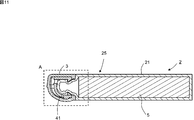
- FIG. 11 is a cross-sectional view of the plane Z in FIG. 1 as viewed from the UL direction in a state in which the mounting member 41 and the corner member 3 are mounted on the base 21.
- FIG. 12 is a partially enlarged view of region A in FIG.
- the protrusion 42 presses the bottom surface 32 of the corner member 3 from the inside of the main body 2, thereby The portion 31) is deformed toward the outside of the protrusion 42. That is, in the present embodiment, the corner member 3 is configured to be deformed by the protrusions 42 when being attached to the attachment portion 4.
- the lid 1 is configured such that the deformed portion 31 protrudes toward the outside of the protrusion 42 by forming the mounting member 41 with plastic and the corner member 3 with an elastomer softer than plastic.
- the corner material 3 protrudes downward (see FIG. 12). And the occurrence of a gap in the mounting surface 10 can be reduced.
- the lid 1 can be easily manufactured, and a gap is generated between the lid 1 and the placement surface 10 while appropriately protecting the corner 22 of the lid 1 (main body 2). Can be reduced.
- the mounting member 41 is omitted and the protrusion 42 is provided on the bottom of the protrusion 23.
- the arm slit 46 is formed by post-processing.
- the mounting member 41 is omitted and the corner material 3 is welded to the main body 2.
- the shape of the protrusion 42 is an arm shape in which the diameter of the portion that contacts the placement surface 10 is increased. -Two or more protrusions 42 are provided.
- the main body 2 is formed by injection molding.
- the attachment method of the attachment member 41 and the corner material 3 is not specifically limited, It can implement
- Embodiment related to structure and manufacturing method When manufacturing a structure, in order to prevent molding defects due to expansion of air inside the structure, holes may be made in the resin molded body to discharge the air inside.
- the present embodiment has been made in view of such circumstances, and provides a structure and a manufacturing method capable of discharging an air pocket even when a spacer member is set up to the vicinity of the inner wall of a resin molded body.
- a hollow resin molded body and a spacer member are provided, the spacer member is disposed in the resin molded body, and the resin molded body includes a parting line, and is disposed on the parting line.
- a structure is provided in which holes are provided.
- a hollow resin molded body includes a parting line.
- a hole is provided on the parting line. The structure can exhaust air from such holes.
- the resin molded body includes an upper surface, a lower surface facing the upper surface, and a connection surface that connects the upper surface and the lower surface, and the holes are provided at corners of the connection surface.
- the peripheral edge portion of the spacer member has a shape along the inner wall of the resin molded body.
- the spacer member includes an upper surface, a lower surface opposite to the upper surface, and a connection surface that connects the upper surface and the lower surface, and a notch that connects the upper surface and the lower surface of the spacer member to the connection surface of the spacer member. Is provided.
- the notch is configured so that air in the resin molded body can be discharged through the hole.
- a hollow waste bag and a hollow air discharge path are provided, the air discharge path is configured to connect the hole and the waste bag, and the waste bag includes an air discharge hole.
- a corner member is provided, and the corner member is attached to the corner portion and configured to seal the hole.
- the method includes a drooping process, an insert process, and a mold clamping process. In the dripping process, the first and second resin sheets are drooped between the first and second molds, and the insert process is performed.
- the spacer member is fixed to the first resin sheet, and in the mold clamping step, the first and second molds are clamped to form a molded body, and the spacer member is between the first and second resin sheets.
- the structure manufacturing method is provided in which air in the molded body can be discharged through a hole provided on a parting line of the molded body in the mold clamping step.
- the first and second molds include a molded body forming portion for forming the molded body, and a discarded bag forming portion for forming a discarded bag communicated with the hole, and the mold clamping step Thereafter, the step of removing the molded body from the first and second molds and cutting the discarded bag formed on the molded body is provided.
- air existing between the first and second resin sheets and the spacer member is discharged through the discard bag.
- corner portions of the spacer member are dissolved by the first and second molds.
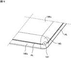
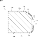
- a structure 150 As shown in FIGS. 15 to 18, a structure 150 according to an embodiment of the present invention includes a hollow resin molded body 140 and a spacer member 130. A parting line PL is formed on the resin molded body 140. The spacer member 130 is disposed in the resin molded body 140. In addition, a hole 141 is provided in the parting line PL.
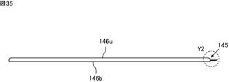
- the resin molded body 140 includes an upper surface 146u, a lower surface 146b facing the upper surface 146u, and a connecting surface 146c that connects the upper surface 146u and the lower surface 146b.
- the hole 141 is provided in the corner
- the structure 150 includes a corner member 134.
- the corner member 134 is attached to the corner portion 145 of the structure 150. Further, the corner member 134 is configured to seal the hole 141.
- FIG. 15 shows a state in which the corner member 134 is removed.
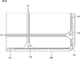
- the peripheral portion 135 of the spacer member 130 has a shape along the inner wall of the resin molded body 140. Further, an air flow path 147 is formed between the hole 141 and the peripheral portion 135 in the direction along the parting line PL (see FIG. 15).
- the spacer member 130 is, for example, a bead foam having an expansion ratio of 25 to 60 times, and a member having a thickness after molding of 15 to 25 mm can be used.
- the expansion ratio is preferably 30 to 55 times, more preferably 40 to 50 times.
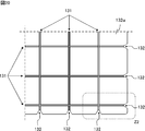
- the spacer member 130 includes an upper surface 133u, a lower surface 133b that faces the upper surface 133u, and a connecting surface 133c that connects the upper surface 133u and the lower surface 133b.
- grooves 131 that are orthogonal to each other are provided on the upper surface 133u.
- the connecting surface 133c of the spacer member 130 is provided with a notch 132 that connects the upper surface 133u and the lower surface 133b.
- the notch 132 is connected to the groove 131 while connecting the upper surface 133u and the lower surface 133b.
- the notch 132 is configured to be able to discharge the air in the resin molded body 140 toward the flow path 147 through the hole 141.
- the notch 132 is a V-shaped notch in plan view.
- the width of the notch 132 is preferably 4 to 10 mm.
- the groove 131 and the notch 132 are used to discharge an air pocket formed between the spacer member 130 and the resin molded body 140. The operation of the groove 131 and the notch 132 will be described later with reference to FIG.
- the spacer member 130 can be formed by cutting the foam from above the foam larger than the spacer member 130 with a cutter having a shape corresponding to the shape of the notch 132. Thereby, when forming the spacer member 130, the notch 132 can be formed together and manufacturing man-hours can be reduced.
- the molding machine 101 includes a resin supply device 102, a T die 118, and first and second molds 121 and 122.
- the resin supply device 102 includes a hopper 112, an extruder 113, and an accumulator 117.
- the extruder 113 and the accumulator 117 are connected via a connecting pipe 125.
- the accumulator 117 and the T die 118 are connected via a connecting pipe 127.
- the hopper 112 is used to feed the raw resin 111 into the cylinder 113a of the extruder 113.
- the form of the raw material resin 111 is not particularly limited, but is usually a pellet.
- the raw material resin is a thermoplastic resin such as polyolefin, and examples of the polyolefin include low density polyethylene, linear low density polyethylene, high density polyethylene, polypropylene, ethylene-propylene copolymer, and mixtures thereof.
- the raw material resin 111 is charged into the cylinder 113a from the hopper 112 and then melted by being heated in the cylinder 113a to become a molten resin.
- a screw is arrange
- a gear device is provided at the base end of the screw, and the screw is driven to rotate by the gear device.
- the number of screws arranged in the cylinder 113a may be one or two or more.
- the molten resin 111 a is pushed out from the resin extrusion port of the cylinder 113 a and injected into the accumulator 117 through the connecting pipe 125.
- the accumulator 117 includes a cylinder 117a and a piston 117b that can slide inside the cylinder 117a, and the molten resin 111a can be stored in the cylinder 117a. Then, by moving the piston 117b after a predetermined amount of foamed resin is stored in the cylinder 117a, the foamed resin is pushed out from the slit provided in the T-die 118 through the connecting pipe 127, and is dropped. Resin sheets 123a and 123b are formed.
- First and second molds 121 and 122 The first and second resin sheets 123 a and 123 b are guided between the first and second molds 121 and 122. As shown in FIG. 22, the first mold 121 is provided with a number of reduced-pressure suction holes (not shown), and the first resin sheet 123 a is sucked under reduced pressure along the cavity 121 b of the first mold 121. It is possible to shape into different shapes.
- the cavity 121b has a shape having a recess 121c, and a pinch-off portion 121d is provided so as to surround the recess 121c.
- a part of the pinch-off portion 121d constitutes a discarded bag forming portion 121e1 having a shape corresponding to the shape of the discarded bag 142 described later.
- the discarded bag forming portion 121e1 is for forming the discarded bag 142 communicated with the hole 141.
- the discarded bag forming portion 121e1 is connected to the recess 121c through the air discharge path forming portion 121e2. Further, the discard bag forming portion 121e1 includes a pin insertion hole 121f through which a pin forming an air discharge hole 143 described later is inserted. In other words, a pin for discharging air is taken in and out through the pin insertion hole 121f.
- portions of the cavity 121b and the recess 121c other than the discarded bag forming portion 121e1 and the air discharge path forming portion 121e2 correspond to the molded body forming portion 121g.
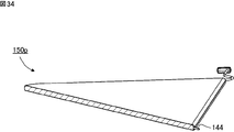
- the molded body forming portion 121g is for forming a molded body 150p (see FIG. 32).
- the second mold 122 is provided with a number of vacuum suction holes (not shown), and the second resin sheet 123b is suctioned under reduced pressure along the cavity 122b of the second mold 122. It is possible to shape into different shapes.
- the cavity 122b has a shape having a recess 122c, and a pinch-off portion 122d is provided so as to surround the recess 122c.
- a part of the pinch-off portion 122d constitutes a discarded bag forming portion 122e1 having a shape corresponding to the shape of the discarded bag 142 described later.
- the discarded bag forming portion 122e1 is for forming the discarded bag 142 communicated with the hole 141.
- the discarded bag forming part 122e1 is connected to the concave part 122c through the air discharge path forming part 122e2.
- portions of the cavity 122b and the concave portion 122c other than the discarded bag forming portion 122e1 and the air discharge path forming portion 122e2 correspond to the molded body forming portion 122g.
- the molded body forming portion 122g is for forming a molded body 150p (see FIG. 32).
- the vacuum suction hole is a very small hole, and one end communicates with the inner surfaces of the cavities 121b and 122b through the first and second molds 121 and 122, and the other end is connected to the decompression device. Has been.
- Method for Manufacturing Structure 150 Next, a method for manufacturing the structure 150 according to an embodiment of the present invention will be described with reference to FIGS.
- the method of this embodiment includes a drooping process, a shaping process, an insert process, and a mold clamping process. Details will be described below.
- the spacer member 130 is disposed between the first and second molds 121 and 122 using a jig (not shown).
- the jig supports the spacer member 130 by sucking the spacer member 130 with a suction cup or the like provided on the jig.
- a first resin sheet 123a formed by extruding a molten foamed resin from the slit of the T die 118 and dripping between the first and second molds 121 and 122 is suspended.
- the first and second resin sheets 123a and 123b are kept at room temperature before forming.
- the solidified first and second resin sheets 123a and 123b are not heated before being molded.
- the spacer member 130 is illustrated between the first and second resin sheets 123a and 123b during the drooping process. However, in the drooping process, the spacer member 130 is made to wait in another place. It may be left.
- the first and second molds 121 and 122 are moved closer to the first and second resin sheets 123a and 123b. Then, as shown in FIG. 28, the first and second molds 121 and 122 suck the first and second resin sheets 123a and 123b under reduced pressure, and the first and second molds 121 and 122 have cavities 121b and 122b. Shape to the shape along.
- the spacer member 130 is set on a jig (not shown). The jig supports the spacer member 130 by sucking the spacer member 130 with a suction cup or the like provided on the jig.
- the spacer member 130 is moved and fixed to the first resin sheet 123a by a jig (not shown).
- the spacer member 130 is a foam
- the spacer is fixed to the first resin sheet 123a by melting the foam by the heat of the first resin sheet 123a.
- the first and second molds 121 and 122 are clamped as shown in FIGS. Thereby, the structure 150 (equivalent to a 1st structure) of the shape along the cavities 121b and 122b of the 1st and 2nd metal molds 121 and 122 is obtained.
- the corner C of the spacer member 130 and the first and second molds 121 and 122 are configured to interfere with each other.
- the corner portion C of the spacer member 130 in the molten state is crushed and melted by the first and second molds 121 and 122, so that the peripheral portion 135 of the spacer member 130 becomes the resin molded body 140.
- the shape is along the inner wall.
- Waste bag 142 Next, the discard bag 142 will be described with reference to FIGS.
- the molded body 150p taken out from the first and second molds 121 and 122 includes a hollow disposal bag 142 and a hollow air discharge path 144. This is formed by the discarded bag forming portions 121e1 and 122e1 and the air discharge path forming portions 121e2 and 121e2 of the first and second molds 121 and 122. Further, in the mold clamping process, the air discharge hole 143 is formed in the disposal bag 142 by the pin output from the pin insertion hole 121 f of the first mold 121.
- the air discharge path 144 is configured to connect the hole 141 and the disposal bag 142.
- the disposal bag 142 includes an air discharge hole 143. That is, in the present embodiment, the air pocket formed between the spacer member 130 and the resin molded body 140 is discharged from the hole 141 through the flow path 147 and reaches the disposal bag 142 through the air discharge path 144. And the air in the disposal bag 142 is discharged
- the molded body 150 p (structure 150) has a shape in which the peripheral portion 135 of the spacer member 130 extends along the inner wall of the resin molded body 140.
- the peripheral portion 135 seals the periphery of the inner wall of the resin molded body 140, so that the space between the spacer member 130 and the first and second resin sheets 123a and 123b. The air pocket formed in the air will not be discharged to the outside.
- the hole 141 is provided on the parting line PL of the resin molded body 140. Also, as shown in FIG. 37, a groove 131 is provided on the upper surface 133u, and a notch 132 is provided on the spacer member 130. As a result, as indicated by the arrows in FIGS. 36 to 38, in the insert process, an air pocket formed between the spacer member 130 and the first resin sheet 123a passes through the groove 131 and the notch 132. It flows into the flow path 147 and is discharged from the hole 141. Then, the air reaches the disposal bag 142 through the air discharge path 144 and is discharged from the air discharge hole 143 to the outside of the structure 150.
- the air remaining between the spacer member 130 and the first resin sheet 123a and the air between the spacer member 130 and the second resin sheet 123b remaining in the insert process are transferred into the grooves 131 and It flows into the flow path 147 through the notch 132 and is discharged from the hole 141. Then, the air reaches the disposal bag 142 through the air discharge path 144 and is discharged from the air discharge hole 143 to the outside of the molded body 150p (structure 150). In other words, in the mold clamping process, the air existing between the first and second resin sheets 123a and 123b and the spacer member 130 is discharged through the disposal bag 142.
- the structure 50 provided with the hole 141 on the parting line PL can be obtained by cutting the air discharge path 144 and the disposal bag 142 formed in the molded body 150p shown in FIG.
- the manufacturing method of the structure 150 is as follows. It has a drooping process, an insert process, and a mold clamping process.
- the first and second resin sheets 123a and 123b are suspended between the first and second molds 121 and 122, and
- the spacer member 130 is fixed to the first resin sheet 123a
- the mold clamping step the first and second molds 121 and 122 are clamped to form a molded body 150p
- the spacer member 130 is disposed between the first and second resin sheets 123a and 123b
- the air in the molded body 150p can be discharged through the holes 141 provided on the parting line of the molded body 150p.
- the method of manufacturing the structure 150 according to the embodiment of the present invention further includes
- the first and second molds 121 and 122 include molded body forming portions 121g and 122g for forming the molded body 150p and discarded bag forming portions 121e1 and 122e1 for forming a discarded bag 142 communicated with the hole 141.
- the molded body 150p is taken out from the first and second molds 121 and 122, A step of cutting the waste bag 142 formed on the molded body 150p to form the structure 150 is provided.
- it is comprised so that a pin may stab in the disposal bag formation part 121e1.
- the hole 141 is formed in the corner portion 145, but the appearance can be prevented from being deteriorated by attaching the corner member 134 to the corner portion 145 and sealing the hole 141. Moreover, since the hole 141 is sealed by the corner material 134, the structure 150 is preferably used as a bath lid, for example.
- the spacer member 130 is set up to the vicinity of the inner wall of the resin molded body 140, the structure 150 capable of discharging the air pocket is realized.
- ⁇ Others> -It is good also as a structure which does not provide the air exhaust path 144 but connects the hole 141 and the disposal bag 142 directly. -You may provide the groove
- hird embodiment an embodiment relating to a resin panel and a manufacturing method
- a resin panel and a manufacturing method are provided.
- the foam comprises a drooping process, an insert process, and a mold clamping process.
- the first and second resin sheets are drooped between the first and second molds, and the insert process
- the foam is welded to the first and second resin sheets, and in the mold clamping step, the first and second molds are clamped, and the foam is disposed between the first and second resin sheets.
- the foam has a convex portion or a concave portion on the second opposing surface on the side facing the second resin sheet, and the convex portion or the concave portion is independent in a 2 cm ⁇ 2 cm reference region of the second opposing surface. Two or more are provided in the state.
- the foam includes a convex portion or a concave portion on the second opposing surface on the side facing the second resin sheet, and is in a 2 cm ⁇ 2 cm reference region of the second opposing surface.
- two or more convex portions or concave portions are provided in an independent state.
- a 2nd resin sheet and a foam can contact the periphery of a convex part or a recessed part partially, and an air pocket can be disperse
- the volume around the convex portion or the concave portion is smaller than that of the groove portion, so that the second resin sheet can be sufficiently melted and the aesthetics are improved.
- the reference area is 3 cm ⁇ 3 cm, and five or more protrusions or recesses are provided in the reference area in an independent state.
- three or more of the convex portions or the concave portions are provided in the adjacent reference regions in an independent state.
- the value of the total area of the protrusions or the recesses in the reference region / the area of the reference region is 0.05 to 1.
- the height of the convex portion or the depth of the concave portion is 1/3 or less of the thickness of the foam.
- the interval between the convex portions or the concave portions is 3 mm or less.
- the convex portion is formed in a tapered shape toward the tip of the convex portion.
- each of the convex portions has a mountain shape.
- each of the recesses is provided discontinuously.
- the foam includes a connecting surface that connects the first facing surface and the second facing surface, and a notch-like air pocket space is formed on the connecting surface.
- a hollow resin molded body and a foam are provided, the foam is disposed in the resin molded body, and the foam includes a facing surface facing one surface of the resin molded body.
- the opposing surface includes a convex portion or a concave portion, and two or more of the convex portions or the concave portions are provided in a 2 cm ⁇ 2 cm reference area of the opposing surface, and the convex portion or the concave portion A resin panel is provided in which a part is melted by the resin sheet on which the resin molded body is formed.
- a resin panel 330 As shown in FIG. 39, a resin panel 330 according to an embodiment of the present invention includes a hollow resin molded body 336 and a foam 331. A parting line PL is formed on the resin molded body 336. The foam 331 is disposed in the resin molded body 336.
- the molding machine 301 includes a resin supply device 302, a T die 318, and first and second molds 321 and 322.
- the resin supply device 302 includes a hopper 312, an extruder 313, and an accumulator 317.
- the extruder 313 and the accumulator 317 are connected via a connecting pipe 325.
- the accumulator 317 and the T die 318 are connected via a connecting pipe 327.
- the hopper 312 is used for charging the raw material resin 311 into the cylinder 313 a of the extruder 313.
- the form of the raw material resin 311 is not particularly limited, but is usually a pellet.
- the raw material resin is a thermoplastic resin such as polyolefin, and examples of the polyolefin include low density polyethylene, linear low density polyethylene, high density polyethylene, polypropylene, ethylene-propylene copolymer, and mixtures thereof. Moreover, you may mix
- the raw material resin 311 is poured into the cylinder 313a from the hopper 312 and then melted by being heated in the cylinder 313a to become a molten resin. Moreover, it is conveyed toward the front-end
- a screw is arrange
- a gear device is provided at the base end of the screw, and the screw is driven to rotate by the gear device.
- the number of screws arranged in the cylinder 313a may be one or two or more.
- the molten resin 311 a is extruded from the resin extrusion port of the cylinder 313 a and is injected into the accumulator 317 through the connecting pipe 325.
- the accumulator 317 includes a cylinder 317a and a piston 317b that can slide inside the cylinder 317a, and the molten resin 311a can be stored in the cylinder 317a. Then, by moving the piston 317b after a predetermined amount of foamed resin is stored in the cylinder 317a, the foamed resin is extruded from the slit provided in the T-die 318 through the connecting pipe 327, and is dropped. Resin sheets 323a and 323b are formed.
- First and second molds 321 and 322 The first and second resin sheets 323a and 323b are guided between the first and second molds 321 and 322. As shown in FIG. 41, the first mold 321 is provided with a number of reduced-pressure suction holes (not shown), and the first resin sheet 323a is sucked under reduced pressure along the cavity 321b of the first mold 321. It is possible to shape into different shapes.
- the cavity 321b has a shape having a recess 321c, and a pinch-off portion 321d is provided so as to surround the recess 321c.
- the second mold 322 is provided with a number of vacuum suction holes (not shown), and the second resin sheet 323b is vacuum-sucked and shaped into a shape along the cavity 322b of the second mold 322. Is possible.
- the cavity 322b has a shape having a recess 322c, and a pinch-off portion 322d is provided so as to surround the recess 322c.
- the decompression suction hole is a very small hole, and one end is connected to the inner surfaces of the cavities 321b and 232b through the first and second molds 321 and 322, and the other end is connected to the decompression device. Has been.
- the method of this embodiment includes a drooping process, a shaping process, an insert process, and a mold clamping process. Details will be described below.
- the timing which processes the 1st resin sheet 323a and the 2nd resin sheet 323b is shifted.
- the foam 331 used for manufacturing the resin panel 330 will be described.
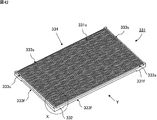
- the foam 331 is disposed in the resin molded body 36, and is, for example, a bead foam having a foaming ratio of 25 to 60 times, and has a thickness after molding of 15 to 25 mm. Can be used.
- the expansion ratio is preferably 30 to 55 times, more preferably 40 to 50 times.
- the foam 331 is selected from resins that can be welded to the first resin sheet 323a and the second resin sheet 323b.
- the foam 331 includes a facing surface that faces one surface of the resin molded body 336. In the present embodiment, as shown in FIGS.
- the foam 331 includes a first opposing surface 331f on the side facing the first resin sheet 323a (described later with reference to FIG. 41), and a second resin sheet 323b.
- the facing surface includes a convex portion 334.
- the foam 331 includes a convex portion 334 on the second facing surface 331 s.
- the convex portion 334 is formed in a tapered shape toward the tip of the convex portion 334. In other words, each of the convex portions 334 has a mountain shape.
- the convex part 34 As a method of providing the convex part 34 on the surface of the foam 331, there is a method of forming the convex part 334 on the surface by post-processing on a flat foam. As another method, there is a method of forming the convex portion 334 by forming a shape corresponding to the convex portion 334 in the mold and transferring the mold shape during foam molding.
- the transfer shape is limited. Therefore, when the latter method is employed, among the tapered shapes, a simple shape such as a mountain shape, in particular, an arc-shaped convex portion or a frustum-shaped convex portion is preferable.
- the shape of the convex part 334 is not limited to these, The aspect which the convex part formed in the surface of the foam 331 by transferring the mesh shape provided in the metal mold
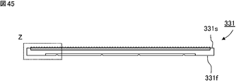
- the convex part 334 is a part which protrudes from the 2nd opposing surface 331s.
- the definition of the convex part 334 is not limited to this. For example, as illustrated in FIG. 46, when the height d from the second facing surface 331 s is defined, a part protruding more than 1 ⁇ 2d is the convex part 334. It is good.
- 100 convex portions 334 are provided in the reference region S.
- the number of convex portions 334 in the reference region S is, for example, 1 to 500.
- the number of protrusions 334 in the reference region S is 2 to 400, more preferably 5 to 300, and still more preferably 9 to 200.
- There are 250, 300, 350, 400, 450, and 500 and may be in the range between any two of the numerical values exemplified here.
- the size of the reference region S is a square of 2 cm ⁇ 2 cm, and 100 convex portions 334 are provided. Moreover, the space
- the size of the reference region S is, for example, 4 to 2,500 cm2. Specifically, they are 2 cm ⁇ 2 cm, 3 cm ⁇ 3 cm, 5 cm ⁇ 5 cm, 10 cm ⁇ 10 cm, 20 cm ⁇ 20 cm, 25 cm ⁇ 25 cm, 50 cm ⁇ 50 cm.
- the reference area S may be other than a square, and may be, for example, a rectangle, a circle, an ellipse, a triangle, a polygon, a star, or the like.
- the reference region S is 3 cm ⁇ 3 cm, it is preferable that five or more convex portions 334 are provided in the reference region S in an independent state (225 in this embodiment).
- the adjacent reference regions S it is preferable that three or more convex portions 334 are provided in the adjacent reference regions S in an independent state.
- the total area of the protrusions 334 in the reference region S / the area of the reference region S is, for example, 0.05 to 1.
- a value is preferably from 0.1 to 0.8, more preferably from 0.2 to 0.7, and even more preferably from 0.3 to 0.6.
- the case where the value of the total area of the protrusions 334 in the reference region S / the area of the reference region S is 1 includes, for example, a mode in which the quadrangular pyramid-shaped protrusions 334 are spread without gaps.
- the area of the convex portion 334 is an area when the convex portion 334 is vertically projected onto the second facing surface 331s. As described above, when the portion protruding from the second facing surface 331s by 1 ⁇ 2d or more is the convex portion 334, the portion protruding from the second facing surface 331s by 1 ⁇ 2d or more is the second facing surface 331s. Is the area when projected vertically.
- the height d of the convex portion 334 is 1/3 or less of the thickness of the foam 331.
- a value is 1/10 or less, more preferably 1/20 or less.
- 1/50, 1/40, 1/30, 1/20, 1/10, 1/5, 1/3 or less and the range between any two of the numerical values exemplified here It may be within.
- the height d of the convex portion 334 is preferably 0.05 to 10 mm. If it is 0.05 mm or less, there is a high possibility that welding will occur before air can escape from the gaps between the projections 334, and if it is 10 mm or more, it is difficult to provide the set number of projections 334 in the reference area S. Because.
- the surface area including the convex portion 334 in the reference region S / the value of the area of the reference region S is, for example, 1.01 to 2.0.
- a value is 1.03 to 1.5, more preferably 1.05 to 1.3.
- 1.01, 1.03, 1.05, 1.1, 1.2, 1.3, 1.4, 1.5, 1.6, 1.7, 1.8, 1.9 and 2.0 and may be within a range between any two of the numerical values exemplified here.
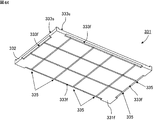
- a groove 335 is provided on the first facing surface 331f of the foam 331. As shown in FIG. Further, a notch-like air pocket space is formed on the connecting surface 332. Specifically, of the connecting surfaces 332, a first air pool space 333f is provided on the first facing surface 331f side, and a second air pool space 333s is provided on the second facing surface 331s side. Each of the grooves 335 communicates with the first air pool space 333f. The significance of the first air pool space 333f and the second air pool space 333s will be described later with reference to FIGS. 48 and 51.
- the resin panel 330 has a structure in which the foam 331 is disposed in the resin molded body 336.
- the fine protrusions 334 are formed on the foam 331 before the resin panel 330 is manufactured.
- the second resin sheet 323b protrudes.
- the portion 334 is melted, and the second facing surface 331 s has a flat shape (described later with reference to FIG. 51). In other words, a part of the convex portion 334 is melted by the second resin sheet 323b on which the resin molded body 336 is formed.
- the first and second resin sheets 323a and 323b are prepared by mixing polypropylene with talc, and the foam 331 is polypropylene having a foaming ratio of 45 times.
- the foam 331 is disposed between the first and second molds 321 and 322 using a jig (not shown). At this time, it arrange
- FIG. 41 the foam 331 is disposed between the first and second molds 321 and 322 using a jig (not shown). At this time, it arrange
- a first resin sheet 323a formed by extruding a foamed resin in a molten state from the slit of the T die 318 and dripping between the first and second molds 321 and 322 is suspended.
- the temperature of the 1st resin sheet 323a at this time is about 200 degreeC.
- the thickness of the first resin sheet 323a is preferably 0.5 to 1 mm, but may be 1 to 1.5 mm.
- the first and second resin sheets 323a and 323b are allowed to have room temperature before forming.
- the solidified first and second resin sheets 323a and 323b are not heated before being molded.
- the foam 331 is illustrated between the first and second resin sheets 323a and 323b during the drooping process. However, in the drooping process, the foam 331 is waited at another place. It may be left.
- the first resin sheet 323a is sucked under reduced pressure by the first mold 321 and shaped into the shape along the cavity 321b of the first mold 321. .
- a jig (not shown) is set on the foam 331.
- the jig supports the foam 331 by sucking the second opposing surface 331s side of the foam 331 with a suction cup or the like provided on the jig.
- the first resin sheet 323a is cooled to 70 to 90 ° C., and then an insert process described later is started.
- a resin cooling step is provided before the below-described insert step.
- the process waits for the temperature of the first resin sheet 23a of about 200 ° C. to cool to 70 to 90 ° C.
- Such temperature is preferably 72 to 88 ° C, more preferably 74 to 86 ° C, and further preferably 76 to 84 ° C.
- 70, 72, 74, 76, 78, 80, 82, 84, 86, 88, 90 ° C. and may be within a range between any two of the numerical values exemplified here. .
- the temperature is preferably an average value.
- an average value of nine temperatures of the first resin sheet 323a can be employed.
- the temperature of the first resin sheet 323a can be measured by a non-contact temperature sensor or the like.
- the temperature of the first resin sheet 323a varies depending on the type of resin and the presence or absence of additives (glass fiber, talc, pigment, etc.). Therefore, the cooling temperature varies depending on the resin used.
- the insert step is started after the first resin sheet is cooled to 70 to 90 ° C.
- the insert step is started after the first resin sheet is cooled to 70 to 90 ° C.
- the foam 331 is moved and fixed to the first resin sheet 323a by a jig (not shown).
- the foam 331 is fixed to the first resin sheet 323a by melting the foam by the heat of the first resin sheet 323a.
- the rigidity of the first resin sheet 323a is improved by waiting for the temperature of the first resin sheet 323a to be cooled to 70 to 90 ° C., the first resin sheet 323a is formed in the groove 335 of the foam 331. Conformity can be reduced.
- the groove 335 provided in the first facing surface 331f of the foam 331 communicates with the first air pool space 333f, it is unintentionally formed between the first resin sheet 323a and the first facing surface 331f.
- the air reservoir can be dispersed in the first air reservoir space 333f through the groove 335. Thereby, even if it is the 1st resin sheet 323a which temperature cooled, it can fully be welded with the 1st opposing surface 331f.
- Second resin sheet 323b 3.3.1 Dripping process In the dripping process, as shown in FIG. 49, a foamed resin in a molten state is extruded from the slit of the T-die 318 and formed between the first and second molds 321 and 322. The second resin sheet 323b is suspended. In this embodiment, the temperature of the 2nd resin sheet 323b at this time is about 200 degreeC. The thickness of the second resin sheet 323b is preferably 0.5 to 1 mm.
- the second resin sheet 323b is sucked under reduced pressure by the second mold 322 and shaped into the shape along the cavity 322b of the second mold 322. .
- the first and second molds 321 and 322 are clamped as shown in FIG. Unlike the first resin sheet 323a, the second resin sheet 323b does not wait for cooling to 70 to 90 ° C., and the second resin sheet 323b and the second facing surface 331s are partially in contact with each other at the convex portion 334. Therefore, even if the thickness of the 2nd resin sheet 323b is comparatively thin, the convex part 334 provided in the 2nd opposing surface 331s of the foam 331 melts
- the temperature of the first resin sheet 323a is lower than the temperature of the second resin sheet 323b.
- the second resin sheet 323b and the second facing surface 331s are not in surface contact, and the second resin sheet 323b and the convex portion 334 are partially in contact with each other.
- an air reservoir is less likely to be formed between the second resin sheet 323b and the second facing surface 331s.
- the air reservoir can be dispersed in the second air reservoir space 333s through the portion of the first facing surface 331f other than the convex portion 334.
- the temperature of the first resin sheet 323a is cooled to 70 to 90 ° C.
- the temperature of the second resin sheet 323b is before being cooled, so the pinch-off portions 321d and 322d cause the first resin sheet 323a and the second resin sheet to be cooled.
- 323b is sufficiently welded to form the parting line PL.
- the molded body is taken out from the first and second molds 321 and 322, and the burr 326 outside the pinch-off portions 321d and 322d is removed, whereby the resin panel 330 shown in FIG. 39 is obtained.
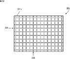
- Modification 1 of the foam 331 according to the present embodiment will be described with reference to FIG. 52, grooves 335 having a narrow interval may be provided in a lattice shape on the second facing surface 331s of the foam 331.
- a portion other than the groove 335 of the second facing surface 331 s has the same function as the above-described convex portion 334.
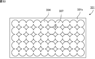
- Modification 2 of the foam 331 according to the present embodiment will be described with reference to FIG.
- the second facing surface 331s on the side facing the second resin sheet 323b is provided with a recess 337, and in the reference region S (see FIG. 43) of the second facing surface 331s, Two or more recesses 337 are provided in an independent state.
- each of the recesses 337 is provided discontinuously.
- the concave portion 337 is formed by a convex portion 334 provided continuously on the second facing surface 331s.
- the depth of the recessed part 337 is 1/3 or less of the thickness of the foam 331.
- ⁇ Others> You may provide the groove
- the present embodiment provides a method for manufacturing a resin molded body that can suppress the occurrence of a step near the parting line of the resin molded body when the timing of injecting two resin sheets is shifted. is there.
- an injection process, a shaping process, and a mold clamping process are provided.
- the first and second resin sheets are injected between the first and second molds, and the first And the second mold each include a cavity
- the shaping step the first and second resin sheets are shaped along the inner surfaces of the cavities of the first and second molds, respectively, and the mold clamping step is performed.
- the first and second molds are clamped, and in the injection step, after starting the injection of the first resin sheet, the injection of the second resin sheet is started, and the edge of the cavity of the first mold is Provided is a method for producing a resin molded body, which is configured to be outside the edge of the cavity of the second mold.
- the present inventor investigated the cause of the occurrence of a step in the vicinity of the parting line of the resin molded body, and when the timing of injecting the two resin sheets was shifted, at the time of clamping, It was found that the portion formed by the resin sheet that started injection had a greater degree of contraction than the portion formed by the resin sheet that started injection later.
- the edge of the cavity of the mold that shapes the resin sheet that has started injection is outside the edge of the cavity that shapes the resin sheet that has started injection later. As a result, it was found that the level difference of the resin molded body can be reduced, and the present invention has been completed.
- the distance between the edge of the cavity of the first mold and the edge of the cavity of the second mold when the first and second molds are in contact with each other is 0. 05 to 1 times.
- an insert process is provided, and in the insert process, the first resin sheet is shaped along the inner surface of the cavity of the first mold, and then the insert member is attached to the first resin sheet.
- the method includes an injection process, a shaping process, an insert process, and a mold clamping process.
- the first and second resin sheets are provided between the first and second molds.
- the first and second molds each have a cavity
- the shaping step the first and second resin sheets are shaped along the inner surfaces of the cavities of the first and second molds, respectively.
- the mold clamping step the first and second molds are clamped, and in the injection step, the injection of the second resin sheet is started after the injection of the first resin sheet is started.
- a method for producing a resin molded body in which an insert member is attached to the first resin sheet after shaping the first resin sheet along the inner surface of the cavity of the first mold.
- the first and second resin sheets are shaped by being sucked under reduced pressure by the first and second molds, respectively.
- the injection of the second resin sheet is started after the first resin sheet is shaped along the inner surface of the cavity of the first mold.
- the first and second resin sheets are shaped so as to be in direct contact with the first and second molds without using another member, respectively.
- the injection of the second resin sheet is started after the insert member is attached to the first resin sheet.
- a resin molded body 401 includes a front wall 403 and a back wall 404.
- the front wall 403 and the back wall 404 are opposed to each other with an interval.
- the periphery of the front wall 403 and the back wall 404 is connected by a peripheral wall 406.
- a parting line PL is provided at substantially the center in the thickness direction of the peripheral wall 406. There is almost no step between the part 406a on the front wall 403 side and the part 406b on the back wall 404 side of the peripheral wall 406 from the parting line PL, and the part 406a and the part 406b are smoothly connected.
- the skin material is not affixed to either the front wall 403 or the back wall 404, it is easy to notice if there is a step in the parting line PL.
- the resin molded body 401 of this embodiment is manufactured by a manufacturing method described later. Therefore, the occurrence of a step is suppressed.
- the insert member 407 is a member that is disposed for the purpose of securing a space between the front wall 403 and the back wall 404 or increasing the strength and heat insulating properties of the resin molded body 401, and is preferably composed of a foam. Is done.
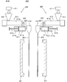
- the molding machine 410 includes a pair of resin sheet forming apparatuses 420 and first and second molds 421 and 431.
- Each resin sheet forming apparatus 420 includes a hopper 412, an extruder 413, an accumulator 417, and a T die 418.
- the extruder 413 and the accumulator 417 are connected via a connecting pipe 425.
- the accumulator 417 and the T die 418 are connected via a connecting pipe 427.
- each configuration will be described in detail.
- the hopper 412 is used to feed the raw resin 411 into the cylinder 413 a of the extruder 413.
- the raw material resin is a thermoplastic resin such as polyolefin, and examples of the polyolefin include low density polyethylene, linear low density polyethylene, high density polyethylene, polypropylene, ethylene-propylene copolymer, and mixtures thereof.
- the raw material resin 411 is poured into the cylinder 413a from the hopper 412 and then melted by being heated in the cylinder 413a to become a molten resin.
- a screw is arrange
- a gear device is provided at the base end of the screw, and the screw is driven to rotate by the gear device.
- the number of screws arranged in the cylinder 413a may be one or two or more.
- the molten resin is extruded from the resin extrusion port of the cylinder 413 a and injected into the accumulator 417 through the connecting pipe 425.
- the accumulator 417 includes a cylinder 417a and a piston 417b that can slide inside the cylinder 417a, and a molten resin can be stored in the cylinder 417a. Then, after a predetermined amount of molten resin is stored in the cylinder 417a, the piston 417b is moved, so that the molten resin is pushed out from the slit provided in the T-die 418 through the connecting pipe 427 and injected to be injected into the first molten state. And second resin sheets 423 and 433 are formed.
- the resin sheets 423 and 433 are injected between the molds 421 and 431.
- the molds 421 and 431 have cavities 421a and 431a, and pinch-off portions 421b and 431b are provided so as to surround the cavities 421a and 431a.
- the cavities 421a and 431a are provided with reduced-pressure suction holes (not shown), and the resin sheets 423 and 433 are suctioned through the reduced-pressure suction holes along the inner surfaces of the cavities 421a and 431a of the molds 421 and 431. It is possible to shape into different shapes.
- the decompression suction hole is a very small hole, and one end thereof communicates with the inner surfaces of the cavities 421a and 431a through the molds 421 and 431, and the other end is connected to the decompression device.
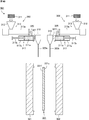
- the distance between the edges 421c and 431c (that is, the step 435) when the molds 421 and 431 are in contact with each other (the state shown in FIG. 57B) is as small as possible at the parting line PL of the resin molded body 401.
- 0.05 to 1 times the thickness of the resin sheet 423 specifically 0.05, 0.1, 0.15, 0.2, 0.25, 0. 3, 0.35, 0.4, 0.45, 0.5, 0.55, 0.6, 0.65, 0.7, 0.75, 0.8, 0.85, 0.9, 0.95 and 1 and may be within a range between any two of the numerical values exemplified here.
- this distance is 0.1 to 2 mm, specifically, for example, 0.1, 0.2, 0.3, 0.4, 0.5, 0.6, 0.7 0.8, 0.9, 1, 1.1, 1.2, 1.3, 1.4, 1.5, 1.6, 1.7, 1.8, 1.9, 2 mm It may be within a range between any two of the numerical values exemplified here.
- the method of the present embodiment includes an injection process, a shaping process, an insert process, and a mold clamping process. Details will be described below.
- the thicknesses of the resin sheets 423 and 433 are the same or different and are, for example, 0.5 to 5 mm, and specifically, for example, 0.5, 1, 1.5, 2, 2.5, 3 , 3.5, 4, 4.5, 5 mm, and may be within a range between any two of the numerical values exemplified here.
- the thickness of the resin sheet 423 is 1.5 mm or less, the resin sheet 423 has a large temperature drop due to contact with the mold 423, and the resin sheet 423 contracts significantly due to the temperature drop. Therefore, the significance of applying the present invention is great.
- the resin sheets 423 and 433 are sucked by the molds 421 and 431 while being in contact with the pinch-off portions 421b and 431b, respectively.
- the resin sheets 423 and 433 are shaped into shapes along the inner surfaces of the cavities 421a and 431a.
- another member such as a skin material is not disposed between the resin sheet 423 and the mold 421 and between the resin sheet 433 and the mold 431, the resin sheets 423 and 433 are respectively , It is shaped so as to be in direct contact with the molds 421,431.
- the timing of shaping the resin sheets 423 and 433 is shifted, only the resin sheet 423 is shaped at the stage of FIG. 59, and the resin sheet 433 is shaped at the stage of FIG.
- the insert member 407 is welded to the resin sheet 423 as shown in FIGS.
- the insert member 407 is formed of a foam
- the foam is melted by the heat of the resin sheet 423, whereby one surface 407 a of the insert member 407 is welded to the resin sheet 423.
- the other surface 407b of the insert member 407 is welded to the resin sheet 433 at the time of mold clamping shown in FIG.
- the temperature of the resin sheet 433 at the time of clamping is increased by that much, and the weldability of the insert member 407 is improved.
- the corner 407c of the insert member 407 is melted and rounded along the inner surface shape of the cavities 421a and 431a.
- molds 421 and 431 are clamped as shown in FIG.
- the resin sheets 423 and 433 are welded to each other along the pinch-off portions 421b and 431b, and a resin molded body 401 having a shape along the inner surface of the cavity formed by the pair of molds 421 and 431 is obtained.
- the outside of the pinch-off portions 421b and 431b is a burr 441.
- the molds 421 and 431 are opened, the resin molded body 401 is taken out, and the burr 441 is removed, whereby the resin molded body 401 shown in FIG. 54 is obtained.
- the temperature of the resin sheet 433 at the time of clamping is increased by that much, and the weldability between the resin sheets 423 and 433 is improved. As a result, the strength of the parting line PL is increased.
- the edge 421c of the cavity 421a of the mold 421 is configured to be outside the edge 431c of the cavity 431a of the mold 431.
- the shrinkage of the resin sheet 423 is offset by the distance between the edge 421c and the edge 431c, and the positions of the bent portions 423a and 433a of the resin sheets 423 and 433 in the vicinity of the pinch-off portions 421b and 431b coincide with each other. Yes.
- FIG. 65 shows a state where the resin molded body 401 is taken out from the molds 421 and 431 from the state shown in FIG.
- the state shown in FIG. 66 is obtained.
- the trace from which the end portion 441a is removed becomes the parting line PL.
- FIG. 69 shows a state where the resin molded body 401 is taken out from the molds 421 and 431 from the state of FIG.
- the burr 441 is removed at the end 441a of the burr 441 from the state shown in FIG. 69
- the state shown in FIG. 70 is obtained.
- the trace from which the end portion 441a is removed becomes the parting line PL.
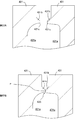
- a groove 437 caused by a step between the resin sheets 423 and 433 is formed at a position adjacent to the parting line PL. Therefore, a step is formed between a portion 406a on the front wall 403 side and a portion 406b on the back wall 404 side of the peripheral wall 406 with respect to the parting line PL.
- the injection of the resin sheet 433 can be started at an arbitrary timing after the injection of the resin sheet 423 is started.
- the injection of the resin sheet 433 may be started before the resin sheet 423 is shaped, after the resin sheet 423 is shaped, before the insert member 407 is pasted, or after the insert member 407 is pasted. From the viewpoint of reducing the temperature drop of the resin sheet 433, the start of the injection of the resin sheet 433 is preferably after the shaping of the resin sheet 423, and more preferably after the pasting of the insert member 407.
- the insert member 407 can be omitted.
Landscapes
- Health & Medical Sciences (AREA)
- Public Health (AREA)
- Epidemiology (AREA)
- General Health & Medical Sciences (AREA)
- Moulds For Moulding Plastics Or The Like (AREA)
Abstract
【課題】製造が容易であり、且つ、蓋のコーナーを適切に保護しつつ蓋と載置面に隙間が生じることを低減することが可能な蓋を提供する。 【解決手段】本発明によれば、開口部を覆う蓋であって、本体と、前記本体のコーナーを保護するコーナー材を備え、前記本体及び前記コーナー材は、互いに異なる素材で形成される、蓋が提供される。
Description
本発明は、開口部を覆う蓋に関するものである。
特許文献1には、蓋本体の周縁部にエッジプロテクターを取付け、当該エッジプロテクターが浴槽のフランジ部の上面に当接するようになっている浴槽用蓋において、前記エッジプロテクターの外周部に、浴槽の上面形状に対応して自在に変形が可能な合成樹脂製チューブ体を形成し、当該合成樹脂製チューブ体を施蓋の際に浴槽のフランジ部の上面に当接させるようにしたことを特徴とする浴槽用蓋が開示されている。
特許文献1に開示される蓋は、蓋本体の周縁部を保護しつつ、施蓋状態において浴槽本体との間に隙間が生ずることを防止できる。しかし、浴槽の上面形状に対応して自在に変形が可能な合成樹脂製チューブ体を設けることにより、製造に工数がかかる。
本発明はこのような事情に鑑みてなされたものであり、製造が容易であり、且つ、蓋のコーナーを適切に保護しつつ蓋と載置面に隙間が生じることを低減することが可能な蓋を提供するものである。
本発明によれば、開口部を覆う蓋であって、本体と、前記本体のコーナーを保護するコーナー材を備え、前記本体及び前記コーナー材は、互いに異なる素材で形成される、蓋が提供される。
本発明に係る蓋1は、本体2と、本体2のコーナー22を保護するコーナー材3を備える。そして、本体2とコーナー材3は、互いに異なる素材で形成される。これにより、コーナー材3により適切に本体2のコーナー22を保護することができるとともに、コーナー材3と載置面の摩擦力により、蓋1が載置面と滑ることを低減することができる。
以下、本発明の種々の実施形態を例示する。以下に示す実施形態は互いに組み合わせ可能である。
好ましくは、前記コーナー材の少なくとも一部はエラストマーで形成される。
好ましくは、前記蓋の載置時に前記本体の底面と前記コーナー材の底面が互いに同一平面になるように構成される。
好ましくは、前記本体は、基部と、前記基部から突出する取付部を備え、前記コーナー材は、前記取付部に装着される。
好ましくは、前記取付部は、前記本体の厚さ方向に突出する突起を備える。
好ましくは、前記コーナー材は、前記取付部への装着時に前記突起により変形するように構成される。
好ましくは、前記突起は、前記本体に設けられたアームに設けられる。
好ましくは、前記取付部は、前記基部から突出する突出部と、前記突出部に装着された取付部材によって構成され、前記突起は、前記取付部材に設けられる。
好ましくは、前記取付部材は、前記突出部の少なくとも一部を収容するように前記突出部に装着される。
好ましくは、前記コーナー材は、前記取付部材の少なくとも一部を収容し、且つその端面が前記基部に接触するように装着される。
好ましくは、前記コーナー材の少なくとも一部はエラストマーで形成される。
好ましくは、前記蓋の載置時に前記本体の底面と前記コーナー材の底面が互いに同一平面になるように構成される。
好ましくは、前記本体は、基部と、前記基部から突出する取付部を備え、前記コーナー材は、前記取付部に装着される。
好ましくは、前記取付部は、前記本体の厚さ方向に突出する突起を備える。
好ましくは、前記コーナー材は、前記取付部への装着時に前記突起により変形するように構成される。
好ましくは、前記突起は、前記本体に設けられたアームに設けられる。
好ましくは、前記取付部は、前記基部から突出する突出部と、前記突出部に装着された取付部材によって構成され、前記突起は、前記取付部材に設けられる。
好ましくは、前記取付部材は、前記突出部の少なくとも一部を収容するように前記突出部に装着される。
好ましくは、前記コーナー材は、前記取付部材の少なくとも一部を収容し、且つその端面が前記基部に接触するように装着される。
以下、本発明の実施形態について説明する。以下に示す実施形態中で示した各種特徴事項は、互いに組み合わせ可能である。また、各特徴について独立して発明が成立する。
(第1の実施形態:蓋に関する実施形態)
1.蓋1
以下、図1~図14を用いて、本発明の本実施形態に係る蓋1について説明する。本実施形態に係る蓋1は、開口部を覆う蓋であり、例えば浴槽を覆う風呂蓋である。図1~図4に示すように、本実施形態では、蓋1は、本体2と、本体2のコーナー22を保護するコーナー材3を備える。
1.蓋1
以下、図1~図14を用いて、本発明の本実施形態に係る蓋1について説明する。本実施形態に係る蓋1は、開口部を覆う蓋であり、例えば浴槽を覆う風呂蓋である。図1~図4に示すように、本実施形態では、蓋1は、本体2と、本体2のコーナー22を保護するコーナー材3を備える。
ここで、一般的な風呂蓋は、浴槽の温度(風呂蓋内面側)と浴室の温度(風呂蓋外面側)との温度差により、風呂蓋に反りが生じる場合がある。かかる反りは、特に角部において生じやすい。そして、風呂蓋の反りに伴い、風呂蓋と浴槽の載置面に隙間が生じ、浴槽の温度が低下してしまう。本実施形態に係る蓋1は、蓋と載置面に隙間が生じることを低減することを目的の1つとするものである。
2.本体2
図1~図4に示すように、本体2は、基体25と取付部材41により構成される。本体2の素材及び形状は特に限定されず、浴槽に合わせて任意の素材及び形状とすることができる。本体2は、樹脂成形体であることが好ましく、真空成形体であることがさらに好ましい。本実施形態では、本体2を構成する原料樹脂は、例えばポリオレフィン等の熱可塑性樹脂であり、ポリオレフィンとしては、低密度ポリエチレン、直鎖状低密度ポリエチレン、高密度ポリエチレン、ポリプロピレン、エチレン-プロピレン共重合体及びその混合物等が挙げられる。また、添加剤を含有してもよい。添加剤としては例えば、シリカ、マイカ、タルク、炭酸カルシウム、ガラス繊維、カーボン繊維等の無機フィラー、可塑剤、安定剤、着色剤、帯電防止剤、難燃剤、発泡剤等が挙げられる。具体的には例えば、シリカ、マイカ、ガラス繊維等を成形樹脂に対して50wt%以下、好ましくは30~40wt%添加する。
図1~図4に示すように、本体2は、基体25と取付部材41により構成される。本体2の素材及び形状は特に限定されず、浴槽に合わせて任意の素材及び形状とすることができる。本体2は、樹脂成形体であることが好ましく、真空成形体であることがさらに好ましい。本実施形態では、本体2を構成する原料樹脂は、例えばポリオレフィン等の熱可塑性樹脂であり、ポリオレフィンとしては、低密度ポリエチレン、直鎖状低密度ポリエチレン、高密度ポリエチレン、ポリプロピレン、エチレン-プロピレン共重合体及びその混合物等が挙げられる。また、添加剤を含有してもよい。添加剤としては例えば、シリカ、マイカ、タルク、炭酸カルシウム、ガラス繊維、カーボン繊維等の無機フィラー、可塑剤、安定剤、着色剤、帯電防止剤、難燃剤、発泡剤等が挙げられる。具体的には例えば、シリカ、マイカ、ガラス繊維等を成形樹脂に対して50wt%以下、好ましくは30~40wt%添加する。
2-1.基体25
本実施形態では、図2に示すように、基体25は、基部21と突出部23により構成される。また、図11~図14に示すように、基体25は中空体であり、その内部に発泡材5が挿入される。発泡材5の材質は特に限定されないが、基体25と同じ材質とすることが好ましい。これは、基体25と発泡材5を同じ材質とすることにより熱溶着が生じ、溶剤等を用いることなく2つの部材を接着させることができるためである。また、発泡材5の発泡倍率は10~30倍であり、好ましくは15~20%である。なお、発泡材5の発泡倍率はこれらに限定されず、剛性及び断熱性を考慮して適宜選定することができる。また、発泡材5は、添加剤を含有してもよい。添加剤としては、シリカ、マイカ、タルク、炭酸カルシウム、ガラス繊維、カーボン繊維等の無機フィラー、可塑剤、安定剤、着色剤、帯電防止剤、難燃剤、発泡剤等が挙げられる。なお、発泡材5は必須ではなく、設計思想に応じて適宜省略することができる。
本実施形態では、図2に示すように、基体25は、基部21と突出部23により構成される。また、図11~図14に示すように、基体25は中空体であり、その内部に発泡材5が挿入される。発泡材5の材質は特に限定されないが、基体25と同じ材質とすることが好ましい。これは、基体25と発泡材5を同じ材質とすることにより熱溶着が生じ、溶剤等を用いることなく2つの部材を接着させることができるためである。また、発泡材5の発泡倍率は10~30倍であり、好ましくは15~20%である。なお、発泡材5の発泡倍率はこれらに限定されず、剛性及び断熱性を考慮して適宜選定することができる。また、発泡材5は、添加剤を含有してもよい。添加剤としては、シリカ、マイカ、タルク、炭酸カルシウム、ガラス繊維、カーボン繊維等の無機フィラー、可塑剤、安定剤、着色剤、帯電防止剤、難燃剤、発泡剤等が挙げられる。なお、発泡材5は必須ではなく、設計思想に応じて適宜省略することができる。
3.基部21及び取付部4
図1~図4に示すように、本体2は、基体25(基部21+突出部23)と、基部21から突出する取付部4を備える。基部21は、略平板状の部材である。ここで、図10Aに示すように、本実施形態では、取付部4は、基部21から突出する突出部23と、突出部23に装着された取付部材41によって構成される。したがって、本実施形態では、コーナー材3は、取付部4に装着されるということができる。なお、本実施形態では、本体2のコーナー22は、突出部23近傍を含むものである。
図1~図4に示すように、本体2は、基体25(基部21+突出部23)と、基部21から突出する取付部4を備える。基部21は、略平板状の部材である。ここで、図10Aに示すように、本実施形態では、取付部4は、基部21から突出する突出部23と、突出部23に装着された取付部材41によって構成される。したがって、本実施形態では、コーナー材3は、取付部4に装着されるということができる。なお、本実施形態では、本体2のコーナー22は、突出部23近傍を含むものである。
図5A及び図5Bに示すように、突出部23は、平面視において突出端236を頂点とする略三角形である。また、突出部23の上面には、後述する取付部材41の上側爪44と係合する上側係合部231が設けられる。また、突出部23の下面には、後述する取付部材41の下側爪45と係合する下側係合部232が設けられる。そして、図6に示すように、基部21から突出するように突出部23が設けられる。突出部23は、基部21に形成された2つの側壁234の間に位置し、上下の傾斜233を経て立設壁面235に接続される。突出部23の厚さは特に限定されないが、基部21の厚さD1の1/2以上であることが好ましい。「突出部23の厚さ/基部21の厚さD1」の値は、具体的には例えば、0.5、0.6、0.7、0.8、0.9であり、ここで例示した数値の何れか2つの間の範囲内であってもよい。ここで、突出部23の厚さを小さくしすぎると、取付部材41及びコーナー材3と基部21の係合が弱くなるため、適宜設計することが好ましい。また、安定性の観点から、突出部23の厚さ方向の中点と、基部21の厚さD1方向の中点が略同一となるように構成されることが好ましい。
次に、取付部材41について説明する。取付部材41は、例えば射出成形により形成されるプラスチックの部材である。取付部材41は、本実施形態では、図7A~図7Cに示すように、平面視において突出端411を頂点とする略三角形の部材である。取付部材41は、内部に突出部23の少なくとも一部を収容する収容空間40を備える。また、収容空間40の内壁は、突出部23の突出端236に沿った形状である。
また、取付部材41の上面には、突出部23の上側係合部231と係合する上側爪44が設けられる。具体的には、上側爪44は、取付部材41の上面に形成された2つの上側スリット47の間に形成される上側アーム47aに設けられる。上側爪44は、上側アーム47aの底面から収容空間40の内部に向けて形成されるものであり、側面視において略三角形である(図11~図14参照)。かかる構成とすることで、取付部材41を突出部23に装着する際に、上側アーム47aごと図7Aの上方向に変形することにより、取付部材41を突出部23に装着しやすくしている。
また、取付部材41には、上側爪44と対向するように、2つの下側爪45が設けられる。下側爪45は、取付部材41の底面から収容空間40の内部に向けて形成されるものであり、側面視において略三角形である(図11~図14参照)。下側爪45はそれぞれ、突出部23の下側係合部232の両端にはめ込まれることにより、突出部23と係合するものである。
かかる構成により、取付部材41は、上側爪44及び下側爪45を突出部23の上側係合部231及び下側係合部232に係合させることにより、突出部23の少なくとも一部を収容するように突出部23に装着される。
また、取付部材41には、収容空間40内部の底面に、略半円弧状のアームスリット46が形成される。これにより、アームスリット46の内側にアーム43が形成される。そして、アーム43の底面(取付部材41の外側の面)に、本体2(基部21)の厚さD1方向に突出する突起42が形成される。ここで、本実施形態では、本体2は、基体25(基部21+突出部23)と取付部4(取付部材41+突出部23)により構成される。このため、取付部4は、本体2の厚さD1方向に突出する突起42を備えるということができる。また、取付部4も本体2の一部であるので、突起42は、本体2に設けられたアーム43に設けられるということができる。
図8に示すように、突起42の高さD3は特に限定されないが、1mm~30mmが好ましい。具体的には例えば、1、2、3、4、5、6、7、8、9、10、11、12、13、14、15、16、17、18、19、20、21、22、23、24、25、26、27、28、29、30mmであり、ここで例示した数値の何れか2つの間の範囲内であってもよい。
また、取付部材41の高さD2/D3の比の値は特に限定されないが、2~50が好ましい。具体的には例えば、2、3、4、5、6、7、8、9、10、11、12、13、14、15、16、17、18、19、20、21、22、23、24、25、26、27、28、29、30、31、32、33、34、35、36、37、38、39、40、41、42、43、44、45、46、47、48、49、50であり、ここで例示した数値の何れか2つの間の範囲内であってもよい。
さらに、取付部材41の側壁における突出端236に相当する箇所と、側壁及び底面49を連結する斜面には、開口部48がそれぞれ1つ及び2つずつ設けられる。本実施形態では、かかる開口部48が略三角形の頂点上に配置される。また、取付部材41の側壁における突出端236に相当する箇所に設けられる開口部48は、幅方向の長さが他の開口部48も長く設定されている。かかる開口部48は、取付部材41を突出部23に装着する際において、取付部材41を適切に変形させるためのものであり、必要に応じて省略してもよい。
4.コーナー材3
コーナー材3は、本体2のコーナー22を保護するものであり、例えば、コーナー材3の少なくとも一部はエラストマーにより形成される。ここで、エラストマーとは、ゴム弾性を有する材料である。コーナー材3がエラストマーで形成されることにより、本体2のコーナー22を適切に保護することができる。なお、本実施形態では、図1に示される2つのコーナー22に着目して説明しており、他のコーナーについては議論しない。
コーナー材3は、本体2のコーナー22を保護するものであり、例えば、コーナー材3の少なくとも一部はエラストマーにより形成される。ここで、エラストマーとは、ゴム弾性を有する材料である。コーナー材3がエラストマーで形成されることにより、本体2のコーナー22を適切に保護することができる。なお、本実施形態では、図1に示される2つのコーナー22に着目して説明しており、他のコーナーについては議論しない。
ここで、エラストマーとしては、具体的には例えば、エチレン-プロピレン共重合体(EPR)、エチレン-プロピレン-ジエン共重合体(EPDM)、エチレン-ブテン共重合体等のオレフィン系エラストマー、スチレンとブタジエンの共重合体から成るSBR等のスチレン系エラストマー、シリコン系エラストマー、ニトリル系エラストマー、アクリレート系エラストマー、ブタジエン系エラストマー、ウレタン系エラストマー、ナイロン系エラストマー、エステル系エラストマー、フッ素系エラストマー、及びこれらのエラストマーの共重合体や、これらに反応部位(二重結合、無水カルボキシル基等)を導入した変性物等が挙げられる。特に、コスト、成形性、耐候性、耐水性、耐酸・アルカリ性に優れ、軽量であるオレフィン系エラストマーが好ましい。
オレフィン系エラストマーとしては、具体的には例えば、ポリブタジエン、ポリイソプレン、スチレン-ブタジエンのランダム共重合体及びブロック共重合体、ブロック共重合体の水素添加物、ブタジエン-イソプレン共重合体等のジエン系エラストマー、エチレン-プロピレンのランダム共重合体及びブロック共重合体、エチレン-ブテンのランダム共重合体及びブロック共重合体、エチレンとα-オレフィンとの共重合体、エチレン-酢酸ビニル等のエチレンと脂肪酸ビニルとの共重合体、エチレン-プロピレン-ヘキサジエン共重合体等のエチレン-プロピレン非共役ジエン3元共重合体、ブチレン-イソプレン共重合体、塩素化ポリエチレン等が好ましい。ここで、エラストマーに公知の改質剤や添加剤を配合しても良い。
さらに、ポリオレフィン系エラストマーのデュロ硬度Aは、外観と防傷性とのバランスの点から、JIS K6253に準拠して、53~85、好ましくは54~83、さらに好ましくは55~81である。また、防傷性の点から、55~70、好ましくは57~70、さらに好ましくは60~70である。また、ポリオレフィン系エラストマーの曲げ弾性率は、突起42による変形性の点から、ASTMD790に準拠して、500MPa以下、好ましくは200MPa以下である。
図9に示すように、コーナー材3は、平面視において突出端37を頂点とする略三角形の部材である。コーナー材3は、内部に取付部材41の少なくとも一部を収容する収容空間36を備える。また、収容空間36の内壁は、取付部材41の突出端411に沿った形状である。
また、図9、図10A及び図10Bに示すように、コーナー材3の上面には、取付部材41の上側爪44並びに突出部23の傾斜233及び立設壁面235により形成される空間内の壁面と係合する上側爪34が設けられる。上側爪34は、コーナー材3の上面から収容空間36の内部に向けて形成されるものであり、側面視において略四角形である(図11~図14参照)。
また、コーナー材3には、上側爪34と対向するように、下側爪35が設けられる。また、下側爪35は、コーナー材3の底面から収容空間36の内部に向けて形成されるものであり、側面視において略四角形である(図11~図14参照)。下側爪35は、上側爪34と同様に、取付部材41の下側爪45並びに突出部23の傾斜233及び立設壁面235により形成される空間内の壁面と係合するものである。
以上説明した種々の部材により、本実施形態に係る蓋1が構成される。具体的には、図10Aに示すように、突出部23の少なくとも一部を収容するように、取付部材41を突出部23に装着する。そして、図10Bに示すように、取付部材41の少なくとも一部を収容するように、コーナー材3を取付部材41に装着する。このとき、コーナー材3の端面33が基部21に接触するように、コーナー材3が取付部材41に装着される。
このように、本体2とコーナー材3の間に取付部材41を設けているのは、本体2とコーナー材3の係合強度を担保するためである。すなわち、取付部材41を設けない場合には、本実施形態ではコーナー材3がエラストマーであるので、本体2からコーナー材3が外れやすくなるためである。
5.蓋1の載置時における変形
次に、蓋1を載置面10に載置した状態における蓋1の変形について、図11~図14を用いて説明する。図11は、基部21に取付部材41及びコーナー材3を装着した状態における、図1の平面ZをUL方向から見た断面図である。また、図12は、図11の領域Aの部分拡大図である。
次に、蓋1を載置面10に載置した状態における蓋1の変形について、図11~図14を用いて説明する。図11は、基部21に取付部材41及びコーナー材3を装着した状態における、図1の平面ZをUL方向から見た断面図である。また、図12は、図11の領域Aの部分拡大図である。
図12に示すように、基部21に取付部材41及びコーナー材3を装着した状態では、突起42が本体2の内側からコーナー材3の底面32を押圧することにより、底面32の一部(変形箇所31)が突起42の外側に向けて変形する。つまり、本実施形態では、コーナー材3は、取付部4への装着時に、突起42により変形するように構成される。本実施形態では、取付部材41をプラスチック、コーナー材3をプラスチックよりも柔らかいエラストマーで形成することにより、変形箇所31が突起42の外側に向けて突出するように蓋1を構成している。
そして、図13及び図14に示すように、蓋1を載置面10に載置した状態において、本体2の底面24とコーナー材3の底面32が互いに同一平面となるように構成される。これは、蓋1の自重により、側面視における点P2を起点とし、アーム43が屈曲変形しつつ本体2の内側に押し込まれ、かかる屈曲変形における復元力により、コーナー材3が側面視における点P1周辺で弾性変形するためである。
本実施形態に係る蓋1を風呂蓋として利用する場合、浴室の温度差により蓋1が上方に反った場合でも、コーナー材3が下方に突出した状態(図12参照)となるので、蓋1と載置面10に隙間が生じることを低減できる。
以上説明したように、本実施形態によれば、蓋1を容易に製造でき、且つ、蓋1(本体2)のコーナー22を適切に保護しつつ蓋1と載置面10に隙間が生じることを低減することが可能となる。
<その他>
本発明は、これらに限定されず、以下の態様とすることもできる。
・取付部材41を省略し、突出部23の底部に突起42を設ける。この場合、アームスリット46は後加工により形成する。
・取付部材41を省略し、本体2にコーナー材3を溶着する。
・突起42の形状を、載置面10と接触する箇所の径を大きくしたアーム形状とする。
・突起42を2つ以上設ける。
・本体2を射出成形により形成する。
・取付部材41及びコーナー材3の装着方法は特に限定されず、挟着、溶着、嵌合等、種々の方法で実現することができる。
本発明は、これらに限定されず、以下の態様とすることもできる。
・取付部材41を省略し、突出部23の底部に突起42を設ける。この場合、アームスリット46は後加工により形成する。
・取付部材41を省略し、本体2にコーナー材3を溶着する。
・突起42の形状を、載置面10と接触する箇所の径を大きくしたアーム形状とする。
・突起42を2つ以上設ける。
・本体2を射出成形により形成する。
・取付部材41及びコーナー材3の装着方法は特に限定されず、挟着、溶着、嵌合等、種々の方法で実現することができる。
(第2の実施形態:構造体及び製造方法に関する実施形態)
構造体を製造する際に、構造体の内部の空気が膨張することによる成形不良を防止するために、樹脂成形体に穴を開けて内部の空気を排出する場合がある。
構造体を製造する際に、構造体の内部の空気が膨張することによる成形不良を防止するために、樹脂成形体に穴を開けて内部の空気を排出する場合がある。
しかし、かかる穴を設けることにより、構造体の美観が損なわれることになる。
本実施形態はこのような事情に鑑みてなされたものであり、樹脂成形体の内壁近傍までスペーサー部材を設定した場合でも、空気溜まりを排出可能な構造体及び製造方法を提供するものである。
本実施形態によれば、中空の樹脂成形体と、スペーサー部材を備え、前記スペーサー部材は、前記樹脂成形体内に配置され、前記樹脂成形体は、パーティングラインを備え、前記パーティングライン上に孔が設けられる、構造体が提供される。
本実施形態に係る構造体は、中空の樹脂成形体がパーティングラインを備える。そして、パーティングライン上に孔が設けられる。構造体は、かかる孔から空気を排出することができる。
以下、本発明の種々の実施形態を例示する。以下に示す実施形態は互いに組み合わせ可能である。
好ましくは、前記樹脂成形体は、上面と、前記上面と対向する下面と、前記上面及び前記下面を連結する連結面を備え、前記孔は、前記連結面の角部に設けられる。
好ましくは、前記スペーサー部材の周縁部は、前記樹脂成形体の内壁に沿った形状となっている。
好ましくは、前記スペーサー部材は、上面と、前記上面と対向する下面と、前記上面及び前記下面を連結する連結面を備え、前記スペーサー部材の連結面に、前記スペーサー部材の上面及び下面を結ぶノッチが設けられる。
好ましくは、前記ノッチは、前記孔を通じて、前記樹脂成形体内の空気が排出可能に構成される。
好ましくは、中空の捨て袋と、中空の空気排出経路を備え、前記空気排出経路は、前記孔と前記捨て袋を接続するように構成され、前記捨て袋は、空気排出孔を備える。
好ましくは、コーナー材を備え、前記コーナー材は、前記角部に取付けられ、且つ、前記孔を封止するように構成される。
他の観点によれば、垂下工程と、インサート工程と、型締工程を備え、前記垂下工程では、第1及び第2金型の間に第1及び第2樹脂シートを垂下させ、前記インサート工程では、スペーサー部材を第1樹脂シートに固着させ、前記型締工程では、第1及び第2金型を型締めして成形体を形成し、前記スペーサー部材は、第1及び第2樹脂シート間に配置され、前記型締工程において前記成形体のパーティングライン上に設けられた孔を通じて、前記成形体内の空気が排出可能になっている、構造体の製造方法が提供される。
好ましくは、第1及び第2金型は、前記成形体を形成するための成形体形成部と、前記孔に連通される捨て袋を形成するための捨て袋形成部を備え、前記型締工程の後、第1及び第2金型から前記成形体を取り出し、前記成形体に形成された前記捨て袋を切断する工程を備える。
好ましくは、前記型締工程において、第1及び第2樹脂シートと前記スペーサー部材の間に存在する空気を、前記捨て袋を介して排出する。
好ましくは、前記型締工程において、第1及び第2金型により前記スペーサー部材の角部を溶解させる。
好ましくは、前記樹脂成形体は、上面と、前記上面と対向する下面と、前記上面及び前記下面を連結する連結面を備え、前記孔は、前記連結面の角部に設けられる。
好ましくは、前記スペーサー部材の周縁部は、前記樹脂成形体の内壁に沿った形状となっている。
好ましくは、前記スペーサー部材は、上面と、前記上面と対向する下面と、前記上面及び前記下面を連結する連結面を備え、前記スペーサー部材の連結面に、前記スペーサー部材の上面及び下面を結ぶノッチが設けられる。
好ましくは、前記ノッチは、前記孔を通じて、前記樹脂成形体内の空気が排出可能に構成される。
好ましくは、中空の捨て袋と、中空の空気排出経路を備え、前記空気排出経路は、前記孔と前記捨て袋を接続するように構成され、前記捨て袋は、空気排出孔を備える。
好ましくは、コーナー材を備え、前記コーナー材は、前記角部に取付けられ、且つ、前記孔を封止するように構成される。
他の観点によれば、垂下工程と、インサート工程と、型締工程を備え、前記垂下工程では、第1及び第2金型の間に第1及び第2樹脂シートを垂下させ、前記インサート工程では、スペーサー部材を第1樹脂シートに固着させ、前記型締工程では、第1及び第2金型を型締めして成形体を形成し、前記スペーサー部材は、第1及び第2樹脂シート間に配置され、前記型締工程において前記成形体のパーティングライン上に設けられた孔を通じて、前記成形体内の空気が排出可能になっている、構造体の製造方法が提供される。
好ましくは、第1及び第2金型は、前記成形体を形成するための成形体形成部と、前記孔に連通される捨て袋を形成するための捨て袋形成部を備え、前記型締工程の後、第1及び第2金型から前記成形体を取り出し、前記成形体に形成された前記捨て袋を切断する工程を備える。
好ましくは、前記型締工程において、第1及び第2樹脂シートと前記スペーサー部材の間に存在する空気を、前記捨て袋を介して排出する。
好ましくは、前記型締工程において、第1及び第2金型により前記スペーサー部材の角部を溶解させる。
1.構造体150
図15~図18に示すように、本発明の一実施形態に係る構造体150は、中空の樹脂成形体140と、スペーサー部材130を備える。樹脂成形体140には、パーティングラインPLが形成される。スペーサー部材130は、樹脂成形体140内に配置される。また、パーティングラインPLには、孔141が設けられる。
図15~図18に示すように、本発明の一実施形態に係る構造体150は、中空の樹脂成形体140と、スペーサー部材130を備える。樹脂成形体140には、パーティングラインPLが形成される。スペーサー部材130は、樹脂成形体140内に配置される。また、パーティングラインPLには、孔141が設けられる。
具体的には、図16~図18に示すように、樹脂成形体140は、上面146uと、上面146uと対向する下面146bと、上面146u及び下面146bを連結する連結面146cを備える。そして、孔141は、連結面146cの角部145に設けられる。
図15に示すように、構造体150は、コーナー材134を備える。本実施形態では、構造体150の角部145にコーナー材134が取付けられる。また、コーナー材134は、孔141を封止するように構成される。なお、図15では、コーナー材134を外した状態を図示している。
図18に示すように、スペーサー部材130の周縁部135は、樹脂成形体140の内壁に沿った形状となっている。また、孔141と周縁部135の間に、パーティングラインPLに沿った方向(図15参照)に空気の流路147が形成される。
2.スペーサー部材130
次に、構造体150の製造に用いるスペーサー部材130について説明する。スペーサー部材130は、例えば発泡倍率25~60倍のビーズ発泡体であり、成形後の厚さが15~25mmとなるものを用いることができる。発泡倍率は、好ましくは、30~55倍、さらに好ましくは、40~50倍である。図19及び図20に示すように、スペーサー部材130は、上面133uと、上面133uと対向する下面133bと、上面133u及び下面133bを連結する連結面133cを備える。また、上面133uには、互いに直交する溝131が設けられる。そして、スペーサー部材130の連結面133cに、上面133u及び下面133bを結ぶノッチ132が設けられる。本実施形態では、ノッチ132は、上面133u及び下面133bを結びつつ、溝131と接続している。また、ノッチ132は、孔141を通じて、樹脂成形体140内の空気を流路147に向けて排出可能に構成される。本実施形態では、ノッチ132は平面視においてV字形状の切込である。また、ノッチ132の幅は4~10mmが好ましい。かかる溝131及びノッチ132は、スペーサー部材130と樹脂成形体140の間に形成される空気溜まりを排出するものである。溝131及びノッチ132の作用については、図20において後述する。
次に、構造体150の製造に用いるスペーサー部材130について説明する。スペーサー部材130は、例えば発泡倍率25~60倍のビーズ発泡体であり、成形後の厚さが15~25mmとなるものを用いることができる。発泡倍率は、好ましくは、30~55倍、さらに好ましくは、40~50倍である。図19及び図20に示すように、スペーサー部材130は、上面133uと、上面133uと対向する下面133bと、上面133u及び下面133bを連結する連結面133cを備える。また、上面133uには、互いに直交する溝131が設けられる。そして、スペーサー部材130の連結面133cに、上面133u及び下面133bを結ぶノッチ132が設けられる。本実施形態では、ノッチ132は、上面133u及び下面133bを結びつつ、溝131と接続している。また、ノッチ132は、孔141を通じて、樹脂成形体140内の空気を流路147に向けて排出可能に構成される。本実施形態では、ノッチ132は平面視においてV字形状の切込である。また、ノッチ132の幅は4~10mmが好ましい。かかる溝131及びノッチ132は、スペーサー部材130と樹脂成形体140の間に形成される空気溜まりを排出するものである。溝131及びノッチ132の作用については、図20において後述する。
かかるスペーサー部材130は、スペーサー部材130よりも大きな発泡体の上側から、ノッチ132の形状に対応した形状のカッターで発泡体を切断することにより形成することができる。これにより、スペーサー部材130を形成する際に、あわせてノッチ132を形成することができ、製造工数を削減することができる。
3.成形機101の構成
次に、図21~図26を用いて、本発明の一実施形態の構造体150の製造方法の実施に利用可能な成形機101について説明する。
次に、図21~図26を用いて、本発明の一実施形態の構造体150の製造方法の実施に利用可能な成形機101について説明する。
成形機101は、樹脂供給装置102と、Tダイ118と、第1及び第2金型121,122を備える。樹脂供給装置102は、ホッパー112と、押出機113と、アキュームレータ117を備える。押出機113とアキュームレータ117は、連結管125を介して連結される。アキュームレータ117とTダイ118は、連結管127を介して連結される。以下、各構成について詳細に説明する。
<ホッパー112,押出機113>
ホッパー112は、原料樹脂111を押出機113のシリンダ113a内に投入するために用いられる。原料樹脂111の形態は、特に限定されないが、通常は、ペレット状である。原料樹脂は、例えばポリオレフィンなどの熱可塑性樹脂であり、ポリオレフィンとしては、低密度ポリエチレン、直鎖状低密度ポリエチレン、高密度ポリエチレン、ポリプロピレン、エチレン-プロピレン共重合体及びその混合物などが挙げられる。原料樹脂111は、ホッパー112からシリンダ113a内に投入された後、シリンダ113a内で加熱されることによって溶融されて溶融樹脂になる。また、シリンダ113a内に配置されたスクリューの回転によってシリンダ113aの先端に向けて搬送される。スクリューは、シリンダ113a内に配置され、その回転によって溶融樹脂を混練しながら搬送する。スクリューの基端にはギア装置が設けられており、ギア装置によってスクリューが回転駆動される。シリンダ113a内に配置されるスクリューの数は、1本でもよく、2本以上であってもよい。
ホッパー112は、原料樹脂111を押出機113のシリンダ113a内に投入するために用いられる。原料樹脂111の形態は、特に限定されないが、通常は、ペレット状である。原料樹脂は、例えばポリオレフィンなどの熱可塑性樹脂であり、ポリオレフィンとしては、低密度ポリエチレン、直鎖状低密度ポリエチレン、高密度ポリエチレン、ポリプロピレン、エチレン-プロピレン共重合体及びその混合物などが挙げられる。原料樹脂111は、ホッパー112からシリンダ113a内に投入された後、シリンダ113a内で加熱されることによって溶融されて溶融樹脂になる。また、シリンダ113a内に配置されたスクリューの回転によってシリンダ113aの先端に向けて搬送される。スクリューは、シリンダ113a内に配置され、その回転によって溶融樹脂を混練しながら搬送する。スクリューの基端にはギア装置が設けられており、ギア装置によってスクリューが回転駆動される。シリンダ113a内に配置されるスクリューの数は、1本でもよく、2本以上であってもよい。
<アキュームレータ117、Tダイ118>
溶融樹脂111aは、シリンダ113aの樹脂押出口から押し出され、連結管125を通じてアキュームレータ117内に注入される。アキュームレータ117は、シリンダ117aとその内部で摺動可能なピストン117bを備えており、シリンダ117a内に溶融樹脂111aが貯留可能になっている。そして、シリンダ117a内に発泡樹脂が所定量貯留された後にピストン117bを移動させることによって、連結管127を通じて発泡樹脂をTダイ118内に設けられたスリットから押し出して垂下させて第1及び第2樹脂シート123a,123bを形成する。
溶融樹脂111aは、シリンダ113aの樹脂押出口から押し出され、連結管125を通じてアキュームレータ117内に注入される。アキュームレータ117は、シリンダ117aとその内部で摺動可能なピストン117bを備えており、シリンダ117a内に溶融樹脂111aが貯留可能になっている。そして、シリンダ117a内に発泡樹脂が所定量貯留された後にピストン117bを移動させることによって、連結管127を通じて発泡樹脂をTダイ118内に設けられたスリットから押し出して垂下させて第1及び第2樹脂シート123a,123bを形成する。
<第1及び第2金型121,122>
第1及び第2樹脂シート123a,123bは、第1及び第2金型121,122間に導かれる。図22に示すように、第1金型121には、多数の減圧吸引孔(不図示)が設けられており、第1樹脂シート123aを減圧吸引して第1金型121のキャビティ121bに沿った形状に賦形することが可能になっている。キャビティ121bは、凹部121cを有する形状になっており、凹部121cを取り囲むようにピンチオフ部121dが設けられている。本実施形態では、ピンチオフ部121dの一部は、後述する捨て袋142の形状に対応した形状の捨て袋形成部121e1を構成する。捨て袋形成部121e1は、孔141に連通される捨て袋142を形成するためのものである。
第1及び第2樹脂シート123a,123bは、第1及び第2金型121,122間に導かれる。図22に示すように、第1金型121には、多数の減圧吸引孔(不図示)が設けられており、第1樹脂シート123aを減圧吸引して第1金型121のキャビティ121bに沿った形状に賦形することが可能になっている。キャビティ121bは、凹部121cを有する形状になっており、凹部121cを取り囲むようにピンチオフ部121dが設けられている。本実施形態では、ピンチオフ部121dの一部は、後述する捨て袋142の形状に対応した形状の捨て袋形成部121e1を構成する。捨て袋形成部121e1は、孔141に連通される捨て袋142を形成するためのものである。
図23に示すように、捨て袋形成部121e1は、空気排出経路形成部121e2を介して凹部121cと接続される。また、捨て袋形成部121e1は、後述する空気排出孔143を形成するピンが挿通されるピン挿通孔121fを備える。換言すると、ピン挿通孔121fを介して、空気を排出するためのピンが出し入れされる。ここで、キャビティ121b及び凹部121cのうち、捨て袋形成部121e1及び空気排出経路形成部121e2以外の部分が成形体形成部121gに相当する。成形体形成部121gは、成形体150p(図32参照)を形成するためのものである。
図24に示すように、第2金型122には、多数の減圧吸引孔(不図示)が設けられており、第2樹脂シート123bを減圧吸引して第2金型122のキャビティ122bに沿った形状に賦形することが可能になっている。キャビティ122bは、凹部122cを有する形状になっており、凹部122cを取り囲むようにピンチオフ部122dが設けられている。本実施形態では、ピンチオフ部122dの一部は、後述する捨て袋142の形状に対応した形状の捨て袋形成部122e1を構成する。捨て袋形成部122e1は、孔141に連通される捨て袋142を形成するためのものである。
図25に示すように、捨て袋形成部122e1は、空気排出経路形成部122e2を介して凹部122cと接続される。ここで、キャビティ122b及び凹部122cのうち、捨て袋形成部122e1及び空気排出経路形成部122e2以外の部分が成形体形成部122gに相当する。成形体形成部122gは、成形体150p(図32参照)を形成するためのものである。
ここで、減圧吸引孔は、極小の孔であり、一端が第1及び第2金型121,122内部を通ってキャビティ121b,122bの内面にまで連通されてり、他端が減圧装置に接続されている。
4.構造体150の製造方法
次に、図26~図36を用いて、本発明の一実施形態の構造体150の製造方法について説明する。本実施形態の方法は、垂下工程と、賦形工程と、インサート工程と、型締工程を備える。以下、詳細に説明する。
次に、図26~図36を用いて、本発明の一実施形態の構造体150の製造方法について説明する。本実施形態の方法は、垂下工程と、賦形工程と、インサート工程と、型締工程を備える。以下、詳細に説明する。
4.1 垂下工程
垂下工程では、図26に示すように、不図示の治具を用いて、スペーサー部材130を第1及び第2金型121,122間に配置する。治具は、治具に設けられた吸盤等により、スペーサー部材130を吸引することで、スペーサー部材130を支持する。
垂下工程では、図26に示すように、不図示の治具を用いて、スペーサー部材130を第1及び第2金型121,122間に配置する。治具は、治具に設けられた吸盤等により、スペーサー部材130を吸引することで、スペーサー部材130を支持する。
そして、第1及び第2金型121,122間に、溶融状態の発泡樹脂をTダイ118のスリットから押し出して垂下させて形成した第1樹脂シート123aを垂下する。本実施形態では、Tダイ118から押し出された第1及び第2樹脂シート123a,123bをそのまま使用するダイレクト真空成形が行われるので、第1及び第2樹脂シート123a,123bは、成形前に室温にまで冷却されて固化されることがなく、固化された第1及び第2樹脂シート123a,123bが成形前に加熱されることもない。ここで、図26では、垂下工程中において、第1及び第2樹脂シート123a,123bの間にスペーサー部材130を図示しているが、垂下工程では、スペーサー部材130を他の場所に待機させておいてもよい。
4.2 賦形工程
次に、図27に示すように、第1及び第2金型121,122を第1及び第2樹脂シート123a,123bに近づける。そして、図28に示すように、第1及び第2金型121,122によって第1及び第2樹脂シート123a,123bを減圧吸引して第1及び第2金型121,122のキャビティ121b,122bに沿った形状に賦形する。また、この時点までに、スペーサー部材130を不図示の治具にセットする。治具は、治具に設けられた吸盤等により、スペーサー部材130を吸引することで、スペーサー部材130を支持する。
次に、図27に示すように、第1及び第2金型121,122を第1及び第2樹脂シート123a,123bに近づける。そして、図28に示すように、第1及び第2金型121,122によって第1及び第2樹脂シート123a,123bを減圧吸引して第1及び第2金型121,122のキャビティ121b,122bに沿った形状に賦形する。また、この時点までに、スペーサー部材130を不図示の治具にセットする。治具は、治具に設けられた吸盤等により、スペーサー部材130を吸引することで、スペーサー部材130を支持する。
4.3 インサート工程
次に、図28に示すように、不図示の治具により、スペーサー部材130を移動させ、第1樹脂シート123aに固着させる。ここで、本実施形態では、スペーサー部材130は発泡体であるので、第1樹脂シート123aの熱によって発泡体が溶融されることによってスペーサー部材130が第1樹脂シート123aに固着される。
次に、図28に示すように、不図示の治具により、スペーサー部材130を移動させ、第1樹脂シート123aに固着させる。ここで、本実施形態では、スペーサー部材130は発泡体であるので、第1樹脂シート123aの熱によって発泡体が溶融されることによってスペーサー部材130が第1樹脂シート123aに固着される。
4.4 型締工程
型締工程では、図30及び図31に示すように、第1及び第2金型121,122を型締めする。これにより、第1及び第2金型121,122のキャビティ121b,122bに沿った形状の構造体150(第1構造体に相当)が得られる。
型締工程では、図30及び図31に示すように、第1及び第2金型121,122を型締めする。これにより、第1及び第2金型121,122のキャビティ121b,122bに沿った形状の構造体150(第1構造体に相当)が得られる。
ここで、本実施形態では、図36に示すように、スペーサー部材130の角部Cと第1及び第2金型121,122が干渉するように構成される。そして、型締工程において、溶融状態のスペーサー部材130の角部Cを第1及び第2金型121,122で押し潰して溶解させることにより、スペーサー部材130の周縁部135が樹脂成形体140の内壁に沿った形状となる。
5. 捨て袋142
次に、図32~図36を用いて、捨て袋142について説明する。型締工程後、第1及び第2金型121,122から取り出した成形体150p(図32参照)は、中空の捨て袋142と、中空の空気排出経路144を備える。これは、第1及び第2金型121,122の捨て袋形成部121e1,122e1及び空気排出経路形成部121e2,121e2により形成されるものである。また、型締工程において、第1金型121のピン挿通孔121fから出力されるピンにより、捨て袋142に空気排出孔143が形成される。
次に、図32~図36を用いて、捨て袋142について説明する。型締工程後、第1及び第2金型121,122から取り出した成形体150p(図32参照)は、中空の捨て袋142と、中空の空気排出経路144を備える。これは、第1及び第2金型121,122の捨て袋形成部121e1,122e1及び空気排出経路形成部121e2,121e2により形成されるものである。また、型締工程において、第1金型121のピン挿通孔121fから出力されるピンにより、捨て袋142に空気排出孔143が形成される。
図33に示すように、空気排出経路144は、孔141と捨て袋142を接続するように構成される。また、捨て袋142は、空気排出孔143を備える。つまり、本実施形態では、スペーサー部材130と樹脂成形体140の間に形成された空気溜まりが流路147を通って孔141から排出され、空気排出経路144を通って捨て袋142まで到着する。そして、捨て袋142内の空気が、空気排出孔143から成形体150p(構造体150)の外部に排出される。
6. 空気の排出
次に、インサート工程及び型締工程において、スペーサー部材130と第1及び第2樹脂シート123a,213bの間に形成される空気溜まりを外部に排出する機能について説明する。
次に、インサート工程及び型締工程において、スペーサー部材130と第1及び第2樹脂シート123a,213bの間に形成される空気溜まりを外部に排出する機能について説明する。
図19、図20及び図34~図36に示すように、成形体150p(構造体150)は、スペーサー部材130の周縁部135が樹脂成形体140の内壁に沿った形状となっている。これにより、孔141を設けない構造体の場合には、樹脂成形体140の内壁の周囲を周縁部135が封止することにより、スペーサー部材130と第1及び第2樹脂シート123a,123bの間に形成された空気溜まりが外部に排出されなくなってしまう。
しかし、本発明の一実施形態の成形体150p(構造体150)は、樹脂成形体140のパーティングラインPL上に孔141が設けられる。また、図37に示されるように、上面133uに溝131が設けられ、スペーサー部材130にノッチ132が設けられる。これにより、図36~図38中の矢印で示されるように、インサート工程の際には、スペーサー部材130と第1樹脂シート123aの間に形成された空気溜まりが溝131及びノッチ132を通って流路147に流れ、孔141から排出される。そして、かかる空気は、空気排出経路144を通って捨て袋142まで到達し、空気排出孔143から構造体150の外部に排出される。
また、型締工程の際には、インサート工程において残留していたスペーサー部材130と第1樹脂シート123aの間の空気と、スペーサー部材130と第2樹脂シート123bの間の空気が、溝131及びノッチ132を通って流路147に流れ、孔141から排出される。そして、かかる空気は、空気排出経路144を通って捨て袋142まで到達し、空気排出孔143から成形体150p(構造体150)の外部に排出される。換言すると、型締工程において、第1及び第2樹脂シート123a,123bとスペーサー部材130の間に存在する空気を、捨て袋142を介して排出する。
そして、図32に示される成形体150pに形成された空気排出経路144及び捨て袋142を切断することにより、パーティングラインPL上に孔141が設けられた構造体50を得ることができる。
換言すると、本発明の一実施形態の構造体150の製造方法は、
垂下工程と、インサート工程と、型締工程を備え、
垂下工程では、第1及び第2金型121,122の間に第1及び第2樹脂シート123a,123bを垂下させ、
インサート工程では、スペーサー部材130を第1樹脂シート123aに固着させ、
型締工程では、第1及び第2金型121,122を型締めして成形体150pを形成し、
スペーサー部材130は、第1及び第2樹脂シート123a,123b間に配置され、
型締工程において成形体150pのパーティングライン上に設けられた孔141を通じて、成形体150p内の空気が排出可能になっている。
垂下工程と、インサート工程と、型締工程を備え、
垂下工程では、第1及び第2金型121,122の間に第1及び第2樹脂シート123a,123bを垂下させ、
インサート工程では、スペーサー部材130を第1樹脂シート123aに固着させ、
型締工程では、第1及び第2金型121,122を型締めして成形体150pを形成し、
スペーサー部材130は、第1及び第2樹脂シート123a,123b間に配置され、
型締工程において成形体150pのパーティングライン上に設けられた孔141を通じて、成形体150p内の空気が排出可能になっている。
また、本発明の一実施形態の構造体150の製造方法はさらに、
第1及び第2金型121,122は、成形体150pを形成するための成形体形成部121g,122gと、孔141に連通される捨て袋142を形成するための捨て袋形成部121e1,122e1を備え、
型締工程の後、第1及び第2金型121,122から成形体150pを取り出し、
成形体150pに形成された捨て袋142を切断し、構造体150を形成する工程を備える。
また、捨て袋形成部121e1には、ピンが刺さるように構成される。
第1及び第2金型121,122は、成形体150pを形成するための成形体形成部121g,122gと、孔141に連通される捨て袋142を形成するための捨て袋形成部121e1,122e1を備え、
型締工程の後、第1及び第2金型121,122から成形体150pを取り出し、
成形体150pに形成された捨て袋142を切断し、構造体150を形成する工程を備える。
また、捨て袋形成部121e1には、ピンが刺さるように構成される。
また、構造体150は、孔141が角部145に形成されるが、コーナー材134を角部145に取付けて孔141を封止することにより、美観が低下することを防止することができる。また、コーナー材134により孔141が封止されるので、構造体150は、例えば風呂蓋として用いることが好適である。
以上説明した製造方法により、樹脂成形体140の内壁近傍までスペーサー部材130を設定した場合でも、空気溜まりを排出可能な構造体150が実現される。
<その他>
・空気排出経路144を設けず、孔141と捨て袋142を直接接続する構成としてもよい。
・溝131を下面133bに設けてもよい。
・空気排出経路144を設けず、孔141と捨て袋142を直接接続する構成としてもよい。
・溝131を下面133bに設けてもよい。
(第3の実施形態:樹脂製パネル及び製造方法に関する実施形態)
本実施形態は、厚みの薄い樹脂シートを用いた場合でも、樹脂シートと発泡体の溶着時に両者の間に空気溜まりが形成されることを低減しつつ、樹脂シートの変形を低減することが可能な樹脂製パネル及び製造方法を提供するものである。
本実施形態は、厚みの薄い樹脂シートを用いた場合でも、樹脂シートと発泡体の溶着時に両者の間に空気溜まりが形成されることを低減しつつ、樹脂シートの変形を低減することが可能な樹脂製パネル及び製造方法を提供するものである。
本実施形態によれば、垂下工程と、インサート工程と、型締工程を備え、前記垂下工程では、第1及び第2金型の間に第1及び第2樹脂シートを垂下させ、前記インサート工程では、発泡体を第1及び第2樹脂シートに溶着させ、前記型締工程では、第1及び第2金型を型締めし、前記発泡体は、第1及び第2樹脂シート間に配置され、前記発泡体は、第2樹脂シートと対向する側の第2対向面に凸部又は凹部を備え、第2対向面の2cm×2cmの基準領域中に、前記凸部又は前記凹部が独立した状態で2個以上設けられる。
本実施形態に係る樹脂製パネルの製造方法は、発泡体は、第2樹脂シートと対向する側の第2対向面に凸部又は凹部を備え、第2対向面の2cm×2cmの基準領域中に、凸部又は凹部が独立した状態で2個以上設けられる。これにより、第2樹脂シートと発泡体が凸部又は凹部の周辺と部分的に接触し、空気溜まりを外縁に分散することができる。さらに、第2樹脂シートの厚みが薄い場合であっても、溝部と比べて凸部又は凹部の周辺の体積の方が小さいので、十分に溶かすことができ、美観が向上する。
以下、本発明の種々の実施形態を例示する。以下に示す実施形態は互いに組み合わせ可能である。
好ましくは、前記基準領域は、3cm×3cmであり、前記基準領域中に、前記凸部又は前記凹部が独立した状態で5個以上設けられる。
好ましくは、隣接した前記基準領域中に、前記凸部又は前記凹部が独立した状態でそれぞれ3個以上設けられる。
好ましくは、前記基準領域中における前記凸部又は前記凹部の総面積/前記基準領域の面積の値が、0.05~1である。
好ましくは、前記凸部の高さ又は前記凹部の深さが、前記発泡体の厚みの1/3以下である。
好ましくは、前記凸部又は前記凹部の間隔は、3mm以下である。
好ましくは、前記凸部は、前記凸部の先端に向けて先細り形状に形成される。
好ましくは、前記凸部は、それぞれが山形状である。
好ましくは、前記凹部は、それぞれが非連続に設けられる。
好ましくは、前記発泡体は、第1対向面及び第2対向面を連結する連結面を備え、前記連結面に、切欠状の空気溜まり空間が形成される。
他の観点によれば、中空の樹脂成形体と、発泡体を備え、前記発泡体は、前記樹脂成形体内に配置され、前記発泡体は、前記樹脂成形体の一面と対向する対向面を備え、前記対向面は、凸部又は凹部を備え、前記対向面の2cm×2cmの基準領域中に、前記凸部又は前記凹部が独立した状態で2個以上設けられ、前記凸部又は前記凹部の一部が、前記樹脂成形体を形成した樹脂シートにより融解されている、樹脂製パネルが提供される。
好ましくは、前記基準領域は、3cm×3cmであり、前記基準領域中に、前記凸部又は前記凹部が独立した状態で5個以上設けられる。
好ましくは、隣接した前記基準領域中に、前記凸部又は前記凹部が独立した状態でそれぞれ3個以上設けられる。
好ましくは、前記基準領域中における前記凸部又は前記凹部の総面積/前記基準領域の面積の値が、0.05~1である。
好ましくは、前記凸部の高さ又は前記凹部の深さが、前記発泡体の厚みの1/3以下である。
好ましくは、前記凸部又は前記凹部の間隔は、3mm以下である。
好ましくは、前記凸部は、前記凸部の先端に向けて先細り形状に形成される。
好ましくは、前記凸部は、それぞれが山形状である。
好ましくは、前記凹部は、それぞれが非連続に設けられる。
好ましくは、前記発泡体は、第1対向面及び第2対向面を連結する連結面を備え、前記連結面に、切欠状の空気溜まり空間が形成される。
他の観点によれば、中空の樹脂成形体と、発泡体を備え、前記発泡体は、前記樹脂成形体内に配置され、前記発泡体は、前記樹脂成形体の一面と対向する対向面を備え、前記対向面は、凸部又は凹部を備え、前記対向面の2cm×2cmの基準領域中に、前記凸部又は前記凹部が独立した状態で2個以上設けられ、前記凸部又は前記凹部の一部が、前記樹脂成形体を形成した樹脂シートにより融解されている、樹脂製パネルが提供される。
1.樹脂製パネル330
図39に示すように、本発明の一実施形態に係る樹脂製パネル330は、中空の樹脂成形体336と、発泡体331を備える。樹脂成形体336には、パーティングラインPLが形成される。また、発泡体331は、樹脂成形体336内に配置される。
図39に示すように、本発明の一実施形態に係る樹脂製パネル330は、中空の樹脂成形体336と、発泡体331を備える。樹脂成形体336には、パーティングラインPLが形成される。また、発泡体331は、樹脂成形体336内に配置される。
2.成形機301の構成
次に、図40及び図41を用いて、本発明の一実施形態の樹脂製パネル330の製造方法の実施に利用可能な成形機301について説明する。
次に、図40及び図41を用いて、本発明の一実施形態の樹脂製パネル330の製造方法の実施に利用可能な成形機301について説明する。
成形機301は、樹脂供給装置302と、Tダイ318と、第1及び第2金型321,322を備える。樹脂供給装置302は、ホッパー312と、押出機313と、アキュームレータ317を備える。押出機313とアキュームレータ317は、連結管325を介して連結される。アキュームレータ317とTダイ318は、連結管327を介して連結される。以下、各構成について詳細に説明する。
<ホッパー312,押出機313>
ホッパー312は、原料樹脂311を押出機313のシリンダ313a内に投入するために用いられる。原料樹脂311の形態は、特に限定されないが、通常は、ペレット状である。原料樹脂は、例えばポリオレフィンなどの熱可塑性樹脂であり、ポリオレフィンとしては、低密度ポリエチレン、直鎖状低密度ポリエチレン、高密度ポリエチレン、ポリプロピレン、エチレン-プロピレン共重合体及びその混合物などが挙げられる。また、これらにガラス繊維、タルク、顔料などの添加剤を配合しても良い。原料樹脂311は、ホッパー312からシリンダ313a内に投入された後、シリンダ313a内で加熱されることによって溶融されて溶融樹脂になる。また、シリンダ313a内に配置されたスクリューの回転によってシリンダ313aの先端に向けて搬送される。スクリューは、シリンダ313a内に配置され、その回転によって溶融樹脂を混練しながら搬送する。スクリューの基端にはギア装置が設けられており、ギア装置によってスクリューが回転駆動される。シリンダ313a内に配置されるスクリューの数は、1本でもよく、2本以上であってもよい。
ホッパー312は、原料樹脂311を押出機313のシリンダ313a内に投入するために用いられる。原料樹脂311の形態は、特に限定されないが、通常は、ペレット状である。原料樹脂は、例えばポリオレフィンなどの熱可塑性樹脂であり、ポリオレフィンとしては、低密度ポリエチレン、直鎖状低密度ポリエチレン、高密度ポリエチレン、ポリプロピレン、エチレン-プロピレン共重合体及びその混合物などが挙げられる。また、これらにガラス繊維、タルク、顔料などの添加剤を配合しても良い。原料樹脂311は、ホッパー312からシリンダ313a内に投入された後、シリンダ313a内で加熱されることによって溶融されて溶融樹脂になる。また、シリンダ313a内に配置されたスクリューの回転によってシリンダ313aの先端に向けて搬送される。スクリューは、シリンダ313a内に配置され、その回転によって溶融樹脂を混練しながら搬送する。スクリューの基端にはギア装置が設けられており、ギア装置によってスクリューが回転駆動される。シリンダ313a内に配置されるスクリューの数は、1本でもよく、2本以上であってもよい。
<アキュームレータ317、Tダイ318>
溶融樹脂311aは、シリンダ313aの樹脂押出口から押し出され、連結管325を通じてアキュームレータ317内に注入される。アキュームレータ317は、シリンダ317aとその内部で摺動可能なピストン317bを備えており、シリンダ317a内に溶融樹脂311aが貯留可能になっている。そして、シリンダ317a内に発泡樹脂が所定量貯留された後にピストン317bを移動させることによって、連結管327を通じて発泡樹脂をTダイ318内に設けられたスリットから押し出して垂下させて第1及び第2樹脂シート323a,323bを形成する。
溶融樹脂311aは、シリンダ313aの樹脂押出口から押し出され、連結管325を通じてアキュームレータ317内に注入される。アキュームレータ317は、シリンダ317aとその内部で摺動可能なピストン317bを備えており、シリンダ317a内に溶融樹脂311aが貯留可能になっている。そして、シリンダ317a内に発泡樹脂が所定量貯留された後にピストン317bを移動させることによって、連結管327を通じて発泡樹脂をTダイ318内に設けられたスリットから押し出して垂下させて第1及び第2樹脂シート323a,323bを形成する。
<第1及び第2金型321,322>
第1及び第2樹脂シート323a,323bは、第1及び第2金型321,322間に導かれる。図41に示すように、第1金型321には、多数の減圧吸引孔(不図示)が設けられており、第1樹脂シート323aを減圧吸引して第1金型321のキャビティ321bに沿った形状に賦形することが可能になっている。キャビティ321bは、凹部321cを有する形状になっており、凹部321cを取り囲むようにピンチオフ部321dが設けられている。第2金型322には、多数の減圧吸引孔(不図示)が設けられており、第2樹脂シート323bを減圧吸引して第2金型322のキャビティ322bに沿った形状に賦形することが可能になっている。キャビティ322bは、凹部322cを有する形状になっており、凹部322cを取り囲むようにピンチオフ部322dが設けられている。ここで、減圧吸引孔は、極小の孔であり、一端が第1及び第2金型321,322内部を通ってキャビティ321b,232bの内面にまで連通されてり、他端が減圧装置に接続されている。
第1及び第2樹脂シート323a,323bは、第1及び第2金型321,322間に導かれる。図41に示すように、第1金型321には、多数の減圧吸引孔(不図示)が設けられており、第1樹脂シート323aを減圧吸引して第1金型321のキャビティ321bに沿った形状に賦形することが可能になっている。キャビティ321bは、凹部321cを有する形状になっており、凹部321cを取り囲むようにピンチオフ部321dが設けられている。第2金型322には、多数の減圧吸引孔(不図示)が設けられており、第2樹脂シート323bを減圧吸引して第2金型322のキャビティ322bに沿った形状に賦形することが可能になっている。キャビティ322bは、凹部322cを有する形状になっており、凹部322cを取り囲むようにピンチオフ部322dが設けられている。ここで、減圧吸引孔は、極小の孔であり、一端が第1及び第2金型321,322内部を通ってキャビティ321b,232bの内面にまで連通されてり、他端が減圧装置に接続されている。
3.樹脂製パネル330の製造方法
次に、図41~図51を用いて、本発明の第3の一実施形態の樹脂製パネル330の製造方法について説明する。本実施形態の方法は、垂下工程と、賦形工程と、インサート工程と、型締工程を備える。以下、詳細に説明する。本実施形態では、第1樹脂シート323aと第2樹脂シート323bを処理するタイミングをずらしている。
次に、図41~図51を用いて、本発明の第3の一実施形態の樹脂製パネル330の製造方法について説明する。本実施形態の方法は、垂下工程と、賦形工程と、インサート工程と、型締工程を備える。以下、詳細に説明する。本実施形態では、第1樹脂シート323aと第2樹脂シート323bを処理するタイミングをずらしている。
3.1 発泡体331
まず、樹脂製パネル330の製造に用いる発泡体331について説明する。図39~図46に示すように、発泡体331は、樹脂成形体36内に配置され、例えば発泡倍率25~60倍のビーズ発泡体であり、成形後の厚さが15~25mmとなるものを用いることができる。発泡倍率は、好ましくは、30~55倍、さらに好ましくは、40~50倍である。また、発泡体331は、第1樹脂シート323a及び第2樹脂シート323bと溶着可能な樹脂から選定される。発泡体331は、樹脂成形体336の一面と対向する対向面を備える。本実施形態では、発泡体331は、図42~図46に示すように、第1樹脂シート323a(図41を用いて後述)と対向する側の第1対向面331fと、第2樹脂シート323b(図41を用いて後述)と対向する第2対向面331sと、第1対向面331f及び第2対向面331sを連結する連結面332を備える。また、対向面は、凸部334を備える。ここで、図42、図43及び図46に示すように、本実施形態では、発泡体331は、第2対向面331sに凸部334を備える。ここで、図46に示すように、本実施形態では、凸部334は、凸部334の先端に向けて先細り形状に形成される。換言すると、凸部334は、それぞれが山形状である。
まず、樹脂製パネル330の製造に用いる発泡体331について説明する。図39~図46に示すように、発泡体331は、樹脂成形体36内に配置され、例えば発泡倍率25~60倍のビーズ発泡体であり、成形後の厚さが15~25mmとなるものを用いることができる。発泡倍率は、好ましくは、30~55倍、さらに好ましくは、40~50倍である。また、発泡体331は、第1樹脂シート323a及び第2樹脂シート323bと溶着可能な樹脂から選定される。発泡体331は、樹脂成形体336の一面と対向する対向面を備える。本実施形態では、発泡体331は、図42~図46に示すように、第1樹脂シート323a(図41を用いて後述)と対向する側の第1対向面331fと、第2樹脂シート323b(図41を用いて後述)と対向する第2対向面331sと、第1対向面331f及び第2対向面331sを連結する連結面332を備える。また、対向面は、凸部334を備える。ここで、図42、図43及び図46に示すように、本実施形態では、発泡体331は、第2対向面331sに凸部334を備える。ここで、図46に示すように、本実施形態では、凸部334は、凸部334の先端に向けて先細り形状に形成される。換言すると、凸部334は、それぞれが山形状である。
なお、発泡体331の表面に凸部34を設ける方法としては、平坦な発泡体に対して、後加工によって表面に凸部334を形成する方法がある。また、他の方法として、発泡体成形時に、金型に凸部334に対応する形状を設けておき、金型形状を転写させることにより、凸部334を形成する方法がある。ここで、前者の場合、作業工数が増えてしまい、また、後者の場合、転写形状が制限される。したがって、後者の方法を採用する場合には、先細り形状の中でも、山形状、特に円弧状の凸部や、錐台形状の凸部等の単純な形状が好ましい。なお、凸部334の形状はこれらに限定されず、金型に設けた網目形状を転写することにより発泡体331の表面に形成される凸部や、複数形状の凸部が混在する態様でもよい。
図43に示すように、第2対向面331sの破線で囲まれた基準領域S中に、凸部334が独立した状態で2個以上設けられる。ここで、基準領域Sは、発泡体331の平面視における部分的な領域である。また、基準領域S中に、凸部334が独立した状態とは、少なくとも基準領域S中において、複数の凸部334が非連続であることである。さらに、図46に示すように、本実施形態では、凸部334とは、第2対向面331sから突出している部分である。ここで、凸部334の定義はこれに限定されず、例えば、図46に示すように、第2対向面331sからの高さdとした場合、1/2d以上突出している部分を凸部334としてもよい。
図43に示すように、本実施形態では、基準領域S中に凸部334が100個設けられる。基準領域Sにおける凸部334の個数は、例えば1~500個である。好ましくは、基準領域Sにおける凸部334の個数は、2~400個、さらに好ましくは、5~300個、さらに好ましくは、9~200個である。具体的には例えば、1、2、3、4、5、6、7、8、9、10、15、20、30、40、50、60、70、80、90、100、150、200、250、300、350、400、450、500個であり、ここで例示した数値の何れか2つの間の範囲内であってもよい。
また、本実施形態では、基準領域Sの大きさは2cm×2cmの正方形であり、凸部334が100個設けられる。また、凸部334の間隔は、3mm以下である。基準領域Sの大きさは、例えば4~2,500cm2である。具体的には、2cm×2cm、3cm×3cm、5cm×5cm、10cm×10cm、20cm×20cm、25cm×25cm、50cm×50cmである。なお、基準領域Sは、正方形以外でもよく、例えば、長方形、円形、楕円形、三角形、多角形、星型等とすることができる。
ここで、基準領域Sを3cm×3cmとした場合、凸部334は、基準領域S中に独立した状態で5個以上(本実施形態では225個)設けられることが好ましい。また、隣接した基準領域Sを観察した場合、隣接した基準領域S中に、凸部334が独立した状態でそれぞれ3個以上設けられることが好ましい。
図43及び図46に示すように、基準領域S中における凸部334の総面積/基準領域Sの面積の値は、例えば、0.05~1である。好ましくは、かかる値は、好ましくは、0.1~0.8、さらに好ましくは、0.2~0.7、さらに好ましくは、0.3~0,6である。具体的には例えば、0.05、0.1、0.2、0.3、0.4、0.5、0.6、0.7、0.8、0.9であり、ここで例示した数値の何れか2つの間の範囲内であってもよい。なお、基準領域S中における凸部334の総面積/基準領域Sの面積の値が1になる場合とは、例えば四角錐形状の凸部334を隙間なく敷き詰めた態様が挙げられる。
ここで、凸部334の面積とは、凸部334を第2対向面331sに垂直投影した場合の面積である。なお、上記のごとく、第2対向面331sから1/2d以上突出している部分を凸部334とした場合には、第2対向面331sから1/2d以上突出している部分を第2対向面331sに垂直投影した場合の面積である。
図46に示すように、本実施形態では、凸部334の高さdが、発泡体331の厚みの1/3以下である。好ましくは、かかる値は、1/10以下、さらに好ましくは、1/20以下である。具体的には例えば、1/50、1/40、1/30、1/20、1/10、1/5、1/3以下であり、ここで例示した数値の何れか2つの間の範囲内であってもよい。
凸部334の高さdは、0.05~10mmが好ましい。0.05mm以下だと、凸部334間の隙間から空気が抜けきる前に溶着する可能性が高くなり、10mm以上だと基準領域内Sに凸部334を設定された個数分設けることが難しいためである。
基準領域Sにおける凸部334を含む表面積/基準領域Sの面積の値は、例えば、1.01~2.0である。好ましくは、かかる値は、1.03~1.5、さらに好ましくは、1.05~1.3である。具体的には例えば、1.01、1.03、1.05、1.1、1.2、1.3、1.4、1.5、1.6、1.7、1.8、1.9、2.0であり、ここで例示した数値の何れか2つの間の範囲内であってもよい。
また、図44に示すように、発泡体331の第1対向面331fに溝335が設けられる。さらに、連結面332に、切欠状の空気溜まり空間が形成される。具体的には、連結面332のうち、第1対向面331fの側に第1空気溜まり空間333fが、第2対向面331sの側に第2空気溜まり空間333sが設けられる。そして、溝335はそれぞれ、第1空気溜まり空間333fに連通する。なお、第1空気溜まり空間333f及び第2空気溜まり空間333sの意義については、図48及び図51を用いて後述する。
以上説明したように、本実施形態に係る樹脂製パネル330は、発泡体331が樹脂成形体336内に配置された構造である。ここで、図39に示すように、樹脂製パネル330の製造前においては発泡体331に微細な凸部334が形成されているが、樹脂製パネル330の完成時には、第2樹脂シート323bにより凸部334が溶けて、第2対向面331sは平坦な形状となっている(図51を用いて後述)。換言すると、凸部334の一部が、樹脂成形体336を形成した第2樹脂シート323bにより融解されている。
次に、各工程について説明する。なお、以下では、第1及び第2樹脂シート323a,323bとして、ポリプロピレンにタルクを混ぜたものを、発泡体331として、発泡倍率45倍のポリプロピレンを用いるものとする。
3.2 第1樹脂シート323a
3.2.1 垂下工程
垂下工程では、図41に示すように、不図示の治具を用いて、発泡体331を第1及び第2金型321,322間に配置する。このとき、第1対向面331fが第1金型321と対向し、第2対向面331sが第2金型322と対向するように配置する。
3.2.1 垂下工程
垂下工程では、図41に示すように、不図示の治具を用いて、発泡体331を第1及び第2金型321,322間に配置する。このとき、第1対向面331fが第1金型321と対向し、第2対向面331sが第2金型322と対向するように配置する。
そして、第1及び第2金型321,322間に、溶融状態の発泡樹脂をTダイ318のスリットから押し出して垂下させて形成した第1樹脂シート323aを垂下する。本実施形態では、このときの第1樹脂シート323aの温度は約200℃である。また、第1樹脂シート323aの厚みは、0.5~1mmが好ましいが、1~1.5mmであってもよい。本実施形態では、Tダイ318から押し出された第1及び第2樹脂シート323a,323bをそのまま使用するダイレクト真空成形が行われるので、第1及び第2樹脂シート323a,323bは、成形前に室温にまで冷却されて固化されることがなく、固化された第1及び第2樹脂シート323a,323bが成形前に加熱されることもない。ここで、図41では、垂下工程中において、第1及び第2樹脂シート323a,323bの間に発泡体331を図示しているが、垂下工程では、発泡体331を他の場所に待機させておいてもよい。
3.2.2 賦形工程
次に、図47に示すように、第1金型321によって第1樹脂シート323aを減圧吸引して第1金型321のキャビティ321bに沿った形状に賦形する。また、この時点までに、不図示の治具を発泡体331にセットする。治具は、治具に設けられた吸盤等により、発泡体331の第2対向面331s側を吸引することで、発泡体331を支持する。そして、賦形工程にて第1樹脂シート323aが賦形された後、第1樹脂シート323aが70~90℃まで冷めてから、後述のインサート工程を開始する。換言すると、後述のインサート工程の前に、樹脂の冷却工程を備える。ここで、本実施形態では、約200℃の第1樹脂シート23aの温度が70~90℃まで冷めるのを待つ。かかる温度は、好ましくは、72~88℃、さらに好ましくは、74~86℃、さらに好ましくは、76~84℃である。具体的には例えば、70、72、74、76、78、80、82、84、86、88、90℃であり、ここで例示した数値の何れか2つの間の範囲内であってもよい。かかる温度は、平均値の値を採用することが好ましい。例えば、第1樹脂シート323aの9点の温度の平均値を採用することができる。ここで、第1樹脂シート323aの温度は、非接触の温度センサー等で計測することができる。
次に、図47に示すように、第1金型321によって第1樹脂シート323aを減圧吸引して第1金型321のキャビティ321bに沿った形状に賦形する。また、この時点までに、不図示の治具を発泡体331にセットする。治具は、治具に設けられた吸盤等により、発泡体331の第2対向面331s側を吸引することで、発泡体331を支持する。そして、賦形工程にて第1樹脂シート323aが賦形された後、第1樹脂シート323aが70~90℃まで冷めてから、後述のインサート工程を開始する。換言すると、後述のインサート工程の前に、樹脂の冷却工程を備える。ここで、本実施形態では、約200℃の第1樹脂シート23aの温度が70~90℃まで冷めるのを待つ。かかる温度は、好ましくは、72~88℃、さらに好ましくは、74~86℃、さらに好ましくは、76~84℃である。具体的には例えば、70、72、74、76、78、80、82、84、86、88、90℃であり、ここで例示した数値の何れか2つの間の範囲内であってもよい。かかる温度は、平均値の値を採用することが好ましい。例えば、第1樹脂シート323aの9点の温度の平均値を採用することができる。ここで、第1樹脂シート323aの温度は、非接触の温度センサー等で計測することができる。
ここで、樹脂の種類、添加剤の有無(ガラス繊維やタルク、顔料など)によって、第1樹脂シート323aの温度はそれぞれ異なる。したがって、用いる樹脂に応じて、上記冷却温度はそれぞれ異なる。
3.2.3 インサート工程
次に、垂下工程の後、第1樹脂シートが70~90℃まで冷めてから、インサート工程を開始する。換言すると、賦形工程にて第1樹脂シートが賦形された後、第1樹脂シートが70~90℃まで冷めてから、インサート工程を開始する。インサート工程では、図48に示すように、不図示の治具により、発泡体331を移動させ、第1樹脂シート323aに固着させる。ここで、本実施形態では、発泡体331は発泡体であるので、第1樹脂シート323aの熱によって発泡体が溶融されることによって発泡体331が第1樹脂シート323aに固着される。本実施形態では、第1樹脂シート323aの温度が70~90℃まで冷めるのを待つことにより、第1樹脂シート323aの剛性が向上するので、発泡体331の溝335に第1樹脂シート323aが沿うことを低減することができる。
次に、垂下工程の後、第1樹脂シートが70~90℃まで冷めてから、インサート工程を開始する。換言すると、賦形工程にて第1樹脂シートが賦形された後、第1樹脂シートが70~90℃まで冷めてから、インサート工程を開始する。インサート工程では、図48に示すように、不図示の治具により、発泡体331を移動させ、第1樹脂シート323aに固着させる。ここで、本実施形態では、発泡体331は発泡体であるので、第1樹脂シート323aの熱によって発泡体が溶融されることによって発泡体331が第1樹脂シート323aに固着される。本実施形態では、第1樹脂シート323aの温度が70~90℃まで冷めるのを待つことにより、第1樹脂シート323aの剛性が向上するので、発泡体331の溝335に第1樹脂シート323aが沿うことを低減することができる。
さらに、発泡体331の第1対向面331fに設けられた溝335が第1空気溜まり空間333fと連通しているので、第1樹脂シート323aと第1対向面331fの間に意図せず形成される空気溜まりを、溝335を通して第1空気溜まり空間333fに分散させることができる。これにより、温度が冷めた第1樹脂シート323aであっても、第1対向面331fと十分に溶着させることができる。
3.3 第2樹脂シート323b
3.3.1 垂下工程
垂下工程では、図49に示すように、第1及び第2金型321,322間に、溶融状態の発泡樹脂をTダイ318のスリットから押し出して垂下させて形成した第2樹脂シート323bを垂下する。本実施形態では、このときの第2樹脂シート323bの温度は約200℃である。また、第2樹脂シート323bの厚みは、0.5~1mmが好ましい。
3.3.1 垂下工程
垂下工程では、図49に示すように、第1及び第2金型321,322間に、溶融状態の発泡樹脂をTダイ318のスリットから押し出して垂下させて形成した第2樹脂シート323bを垂下する。本実施形態では、このときの第2樹脂シート323bの温度は約200℃である。また、第2樹脂シート323bの厚みは、0.5~1mmが好ましい。
3.3.2 賦形工程
次に、図50に示すように、第2金型322によって第2樹脂シート323bを減圧吸引して第2金型322のキャビティ322bに沿った形状に賦形する。
次に、図50に示すように、第2金型322によって第2樹脂シート323bを減圧吸引して第2金型322のキャビティ322bに沿った形状に賦形する。
3.4 型締工程
型締工程では、図51に示すように、第1及び第2金型321,322を型締めする。第2樹脂シート323bについては、第1樹脂シート323aと異なり、70~90℃まで冷めるのを待たず、第2樹脂シート323bと第2対向面331sが凸部334において部分的に接触しているので、発泡体331の第2対向面331sに設けられた凸部334は、第2樹脂シート323bの厚みが比較的薄い場合であっても、第2樹脂シート323bの温度により溶ける。これにより、第2対向面331sが略平坦な形状になる。ここで、型締め時には、第1樹脂シート323aの温度の方が第2樹脂シート323bの温度より低くなっている。
型締工程では、図51に示すように、第1及び第2金型321,322を型締めする。第2樹脂シート323bについては、第1樹脂シート323aと異なり、70~90℃まで冷めるのを待たず、第2樹脂シート323bと第2対向面331sが凸部334において部分的に接触しているので、発泡体331の第2対向面331sに設けられた凸部334は、第2樹脂シート323bの厚みが比較的薄い場合であっても、第2樹脂シート323bの温度により溶ける。これにより、第2対向面331sが略平坦な形状になる。ここで、型締め時には、第1樹脂シート323aの温度の方が第2樹脂シート323bの温度より低くなっている。
本実施形態では、第2樹脂シート323bと第2対向面331sが面接触せずに、第2樹脂シート323bと凸部334が部分的に接触しているので、従来のように発泡体に溝部を設けた場合と比べ、第2樹脂シート323bと第2対向面331sの間に空気溜まりが形成されにくい。さらに、それでも空気溜まりが形成された場合には、第1対向面331fのうち凸部334以外の部分を通って、空気溜まりを第2空気溜まり空間333sに分散させることができる。さらに、第1樹脂シート323aの温度が70~90℃まで冷めているが、第2樹脂シート323bの温度は冷める前であるので、ピンチオフ部321d,322dにより第1樹脂シート323a及び第2樹脂シート323bが十分に溶着され、パーティングラインPLが形成される。
これにより、第1及び第2金型321,322のキャビティ321b,322bに沿った形状の成形体が得られる。
そして、第1及び第2金型321,322から成形体を取り出し、ピンチオフ部321d,322dの外側のバリ326を除去することによって、図39に示される樹脂製パネル330が得られる。
<変形例1>
次に、図52を用いて、本実施形態に係る発泡体331の変形例1について説明する。図52に示すように、発泡体331の第2対向面331sに間隔の狭い溝335を格子状に設けてもよい。変形例1では、第2対向面331sの溝335以外の部分が、上述の凸部334と同様の機能を奏する。
次に、図52を用いて、本実施形態に係る発泡体331の変形例1について説明する。図52に示すように、発泡体331の第2対向面331sに間隔の狭い溝335を格子状に設けてもよい。変形例1では、第2対向面331sの溝335以外の部分が、上述の凸部334と同様の機能を奏する。
<変形例2>
次に、図53を用いて、本実施形態に係る発泡体331の変形例2について説明する。図53に示すように、変形例2では、第2樹脂シート323bと対向する側の第2対向面331sに凹部337を備え、第2対向面331sの基準領域S(図43参照)中に、凹部337が独立した状態で2個以上設けられる。本変形例では、凹部337は、それぞれが非連続に設けられる。ここで、かかる凹部337は、第2対向面331sに連続的に設けられた凸部334により形成される。また、凹部337の深さは、発泡体331の厚みの1/3以下であることが好ましい。
次に、図53を用いて、本実施形態に係る発泡体331の変形例2について説明する。図53に示すように、変形例2では、第2樹脂シート323bと対向する側の第2対向面331sに凹部337を備え、第2対向面331sの基準領域S(図43参照)中に、凹部337が独立した状態で2個以上設けられる。本変形例では、凹部337は、それぞれが非連続に設けられる。ここで、かかる凹部337は、第2対向面331sに連続的に設けられた凸部334により形成される。また、凹部337の深さは、発泡体331の厚みの1/3以下であることが好ましい。
<その他>
・第1対向面331f及び第2対向面331sに、溝335を設けてもよい。
・第1対向面331f及び第2対向面331sに、凸部334を設けてもよい。
・凸部は間引かれていてもよい。
・第1対向面331f及び第2対向面331sに、溝335を設けてもよい。
・第1対向面331f及び第2対向面331sに、凸部334を設けてもよい。
・凸部は間引かれていてもよい。
(第4の実施形態:樹脂成形体の製造方法に関する実施形態)
本実施形態は、2枚の樹脂シートを射出させるタイミングをずらした場合に樹脂成形体のパーティングライン近傍に段差が発生することを抑制することができる樹脂成形体の製造方法を提供するものである。
本実施形態は、2枚の樹脂シートを射出させるタイミングをずらした場合に樹脂成形体のパーティングライン近傍に段差が発生することを抑制することができる樹脂成形体の製造方法を提供するものである。
本実施形態によれば、射出工程と、賦形工程と、型締め工程を備え、前記射出工程では、第1及び第2金型の間に第1及び第2樹脂シートを射出させ、第1及び第2金型は、それぞれ、キャビティを備え、前記賦形工程では、第1及び第2樹脂シートをそれぞれ第1及び第2金型のキャビティの内面に沿って賦形し、前記型締め工程では、第1及び第2金型を型締めし、前記射出工程では、第1樹脂シートの射出を開始した後に、第2樹脂シートの射出が開始され、第1金型のキャビティの縁が、第2金型のキャビティの縁よりも外側になるように構成されている、樹脂成形体の製造方法が提供される。
本発明者は、樹脂成形体のパーティングライン近傍に段差が発生する原因について調査を行ったところ、2枚の樹脂シートを射出させるタイミングをずらした場合には、型締めの時点において、先に射出を開始させた樹脂シートによって構成された部位が、後に射出を開始させた樹脂シートによって構成された部位よりも収縮の程度が大きくなるためであることが分かった。
そして、このような知見に基づき、先に射出を開始させた樹脂シートを賦形する金型のキャビティの縁が、後に射出を開始させた樹脂シートを賦形するキャビティの縁よりも外側になるように構成したところ、樹脂成形体の段差を低減することができることを見出し、本発明の完成に到った。
以下、本発明の種々の実施形態を例示する。以下に示す実施形態は互いに組み合わせ可能である。
好ましくは、第1及び第2金型が当接した状態での第1金型のキャビティの縁と第2金型のキャビティの縁の間の距離が、第1樹脂シートの厚さの0.05~1倍である。
好ましくは、インサート工程を備え、前記インサート工程では、第1樹脂シートを第1金型のキャビティの内面に沿って賦形した後に第1樹脂シートにインサート部材が貼り付けられる。
好ましくは、第1及び第2金型が当接した状態での第1金型のキャビティの縁と第2金型のキャビティの縁の間の距離が、第1樹脂シートの厚さの0.05~1倍である。
好ましくは、インサート工程を備え、前記インサート工程では、第1樹脂シートを第1金型のキャビティの内面に沿って賦形した後に第1樹脂シートにインサート部材が貼り付けられる。
本発明の別の観点によれば、射出工程と、賦形工程と、インサート工程、型締め工程を備え、前記射出工程では、第1及び第2金型の間に第1及び第2樹脂シートを射出させ、第1及び第2金型は、それぞれ、キャビティを備え、前記賦形工程では、第1及び第2樹脂シートをそれぞれ第1及び第2金型のキャビティの内面に沿って賦形し、前記型締め工程では、第1及び第2金型を型締めし、前記射出工程では、第1樹脂シートの射出を開始した後に、第2樹脂シートの射出が開始され、前記インサート工程では、第1樹脂シートを第1金型のキャビティの内面に沿って賦形した後に第1樹脂シートにインサート部材が貼り付けられる、樹脂成形体の製造方法が提供される。
好ましくは、第1及び第2樹脂シートは、それぞれ第1及び第2金型によって減圧吸引されて賦形される。
好ましくは、第1樹脂シートを第1金型のキャビティの内面に沿って賦形した後に第2樹脂シートの射出が開始される。
好ましくは、第1及び第2樹脂シートは、それぞれ、別の部材を介さずに、第1及び第2金型に直接接触するように賦形される。
好ましくは、第1樹脂シートにインサート部材が貼り付けられた後に第2樹脂シートの射出が開始される。
好ましくは、第1樹脂シートを第1金型のキャビティの内面に沿って賦形した後に第2樹脂シートの射出が開始される。
好ましくは、第1及び第2樹脂シートは、それぞれ、別の部材を介さずに、第1及び第2金型に直接接触するように賦形される。
好ましくは、第1樹脂シートにインサート部材が貼り付けられた後に第2樹脂シートの射出が開始される。
1.樹脂成形体の構造
図54に示すように、本発明の第4の実施形態の樹脂成形体401は、表壁403と、裏壁404を備える。表壁403と裏壁404は、間隔をおいて対向している。表壁403と裏壁404の周囲は、周囲壁406によって繋がれている。周囲壁406の厚さ方向の略中央には、パーティングラインPLが設けられている。周囲壁406の、パーティングラインPLよりも表壁403側の部位406aと裏壁404側の部位406bの間には段差がほとんどなく、部位406aと部位406bはスムーズに繋がっている。表壁403と裏壁404のどちらにも表皮材が貼られていないので、パーティングラインPLに段差があれば目立ちやすいが、本実施形態の樹脂成形体401では、後述する製法によって製造されているので、段差の発生が抑制されている。
図54に示すように、本発明の第4の実施形態の樹脂成形体401は、表壁403と、裏壁404を備える。表壁403と裏壁404は、間隔をおいて対向している。表壁403と裏壁404の周囲は、周囲壁406によって繋がれている。周囲壁406の厚さ方向の略中央には、パーティングラインPLが設けられている。周囲壁406の、パーティングラインPLよりも表壁403側の部位406aと裏壁404側の部位406bの間には段差がほとんどなく、部位406aと部位406bはスムーズに繋がっている。表壁403と裏壁404のどちらにも表皮材が貼られていないので、パーティングラインPLに段差があれば目立ちやすいが、本実施形態の樹脂成形体401では、後述する製法によって製造されているので、段差の発生が抑制されている。
表壁403と裏壁404の間にはインサート部材407(図63を参照)が設けられている。インサート部材407は、表壁403と裏壁404の間のスペースを確保したり、樹脂成形体401の強度や断熱性を高めたりする目的で配置される部材であり、好ましくは、発泡体で構成される。
2.成形機410
次に、図55~図57を用いて、本発明の第3の実施形態の樹脂成形体の製造方法の実施に利用可能な成形機410について説明する。成形機410は、一対の樹脂シート形成装置420と、第1及び第2金型421,431を備える。各樹脂シート形成装置420は、ホッパー412と、押出機413と、アキュームレータ417と、Tダイ418を備える。押出機413とアキュームレータ417は、連結管425を介して連結される。アキュームレータ417とTダイ418は、連結管427を介して連結される。
以下、各構成について詳細に説明する。
次に、図55~図57を用いて、本発明の第3の実施形態の樹脂成形体の製造方法の実施に利用可能な成形機410について説明する。成形機410は、一対の樹脂シート形成装置420と、第1及び第2金型421,431を備える。各樹脂シート形成装置420は、ホッパー412と、押出機413と、アキュームレータ417と、Tダイ418を備える。押出機413とアキュームレータ417は、連結管425を介して連結される。アキュームレータ417とTダイ418は、連結管427を介して連結される。
以下、各構成について詳細に説明する。
<ホッパー412,押出機413>
ホッパー412は、原料樹脂411を押出機413のシリンダ413a内に投入するために用いられる。原料樹脂411の形態は、特に限定されないが、通常は、ペレット状である。原料樹脂は、例えばポリオレフィンなどの熱可塑性樹脂であり、ポリオレフィンとしては、低密度ポリエチレン、直鎖状低密度ポリエチレン、高密度ポリエチレン、ポリプロピレン、エチレン-プロピレン共重合体及びその混合物などが挙げられる。原料樹脂411は、ホッパー412からシリンダ413a内に投入された後、シリンダ413a内で加熱されることによって溶融されて溶融樹脂になる。また、シリンダ413a内に配置されたスクリューの回転によってシリンダ413aの先端に向けて搬送される。スクリューは、シリンダ413a内に配置され、その回転によって溶融樹脂を混練しながら搬送する。スクリューの基端にはギア装置が設けられており、ギア装置によってスクリューが回転駆動される。シリンダ413a内に配置されるスクリューの数は、1本でもよく、2本以上であってもよい。
ホッパー412は、原料樹脂411を押出機413のシリンダ413a内に投入するために用いられる。原料樹脂411の形態は、特に限定されないが、通常は、ペレット状である。原料樹脂は、例えばポリオレフィンなどの熱可塑性樹脂であり、ポリオレフィンとしては、低密度ポリエチレン、直鎖状低密度ポリエチレン、高密度ポリエチレン、ポリプロピレン、エチレン-プロピレン共重合体及びその混合物などが挙げられる。原料樹脂411は、ホッパー412からシリンダ413a内に投入された後、シリンダ413a内で加熱されることによって溶融されて溶融樹脂になる。また、シリンダ413a内に配置されたスクリューの回転によってシリンダ413aの先端に向けて搬送される。スクリューは、シリンダ413a内に配置され、その回転によって溶融樹脂を混練しながら搬送する。スクリューの基端にはギア装置が設けられており、ギア装置によってスクリューが回転駆動される。シリンダ413a内に配置されるスクリューの数は、1本でもよく、2本以上であってもよい。
<アキュームレータ417、Tダイ418>
溶融樹脂は、シリンダ413aの樹脂押出口から押し出され、連結管425を通じてアキュームレータ417内に注入される。アキュームレータ417は、シリンダ417aとその内部で摺動可能なピストン417bを備えており、シリンダ417a内に溶融樹脂が貯留可能になっている。そして、シリンダ417a内に溶融樹脂が所定量貯留された後にピストン417bを移動させることによって、連結管427を通じて溶融樹脂をTダイ418内に設けられたスリットから押し出して射出させて溶融状態の第1及び第2樹脂シート423,433を形成する。
溶融樹脂は、シリンダ413aの樹脂押出口から押し出され、連結管425を通じてアキュームレータ417内に注入される。アキュームレータ417は、シリンダ417aとその内部で摺動可能なピストン417bを備えており、シリンダ417a内に溶融樹脂が貯留可能になっている。そして、シリンダ417a内に溶融樹脂が所定量貯留された後にピストン417bを移動させることによって、連結管427を通じて溶融樹脂をTダイ418内に設けられたスリットから押し出して射出させて溶融状態の第1及び第2樹脂シート423,433を形成する。
<金型421,431>
樹脂シート423,433は、金型421,431の間に射出される。図56~図57に示すように、金型421,431は、キャビティ421a,431aを有し、キャビティ421a,431aを取り囲むようにピンチオフ部421b,431bが設けられている。キャビティ421a,431a内には、減圧吸引孔(図示せず)が設けられており、減圧吸引孔を通じて樹脂シート423,433を減圧吸引して金型421,431のキャビティ421a,431aの内面に沿った形状に賦形することが可能になっている。減圧吸引孔は、極小の孔であり、一端が金型421,431内部を通ってキャビティ421a,431aの内面にまで連通されてり、他端が減圧装置に接続されている。
樹脂シート423,433は、金型421,431の間に射出される。図56~図57に示すように、金型421,431は、キャビティ421a,431aを有し、キャビティ421a,431aを取り囲むようにピンチオフ部421b,431bが設けられている。キャビティ421a,431a内には、減圧吸引孔(図示せず)が設けられており、減圧吸引孔を通じて樹脂シート423,433を減圧吸引して金型421,431のキャビティ421a,431aの内面に沿った形状に賦形することが可能になっている。減圧吸引孔は、極小の孔であり、一端が金型421,431内部を通ってキャビティ421a,431aの内面にまで連通されてり、他端が減圧装置に接続されている。
図57Bに示すように、ピンチオフ部421b,431bが当接するまで金型421,431を近づけると、ピンチオフ部421b,431bの先端面が互いに当接する。この当接する面がパーティング面Pである。金型421のキャビティ421aの縁421cが、金型431のキャビティ431aの縁431cよりも外側になるように構成されているので、金型421,431と閉じたときにパーティング面Pにおいて、縁421c,431cの間に段差435が設けられる。樹脂シート423,433を射出するタイミングをずらした場合、樹脂成形体401のパーティングラインPLに段差が発生しやすいが、本実施形態のように縁421cと縁431cの位置をずらずことによって樹脂成形体401に段差が発生することが抑制される。その原理は、後述する。
金型421,431が当接した状態(図57Bの状態)での縁421c,431c間の距離(つまり、段差435)は、樹脂成形体401のパーティングラインPLでの段差ができるだけ小さくなるように設定され、例えば、樹脂シート423の厚さの0.05~1倍であり、具体的には例えば、0.05、0.1、0.15、0.2、0.25、0.3、0.35、0.4、0.45、0.5、0.55、0.6、0.65、0.7、0.75、0.8、0.85、0.9、0.95、1であり、ここで例示した数値の何れか2つの間の範囲内であってもよい。この距離は、別の表現では、0.1~2mmであり、具体的には例えば、0.1、0.2、0.3、0.4、0.5、0.6、0.7、0.8、0.9、1、1.1、1.2、1.3、1.4、1.5、1.6、1.7、1.8、1.9、2mmであり、ここで例示した数値の何れか2つの間の範囲内であってもよい。
3.樹脂成形体の製造方法
ここで、図58~図63を用いて、本発明の第4の実施形態の樹脂成形体401の製造方法について説明する。本実施形態の方法は、射出工程と、賦形工程と、インサート工程と、型締め工程を備える。以下、詳細に説明する。
ここで、図58~図63を用いて、本発明の第4の実施形態の樹脂成形体401の製造方法について説明する。本実施形態の方法は、射出工程と、賦形工程と、インサート工程と、型締め工程を備える。以下、詳細に説明する。
3-1.射出工程
射出工程では、図58~図60に示すように、金型421,431の間に樹脂シート423,433を射出させる。本実施形態では樹脂シート423,433を射出させるタイミングがずれており、図58の段階では、樹脂シート423のみが射出され、図60の段階で、樹脂シート433の射出が開始される。樹脂シート423,433を射出させるタイミングをずらすのは、インサート部材407が樹脂シート433に溶着されるまでの樹脂シート433の温度低下を小さくして溶着性を向上させることである。インサート部材407は、樹脂シート423に溶着された後に樹脂シート433に溶着されるので、本実施形態では、樹脂シート423を樹脂シート433よりも先に射出している。樹脂シート423,433の厚さは、同一又は異なっており、それぞれ、例えば0.5~5mmであり、具体的には例えば、0.5、1、1.5、2、2.5、3、3.5、4、4.5、5mmであり、ここで例示した数値の何れか2つの間の範囲内であってもよい。樹脂シート423の厚さが1.5mm以下である場合には、樹脂シート423が金型423に接触することによる樹脂シート423の温度低下が大きく、温度低下に伴う樹脂シート423の収縮が顕著になるので、本発明を適用する意義が大きい。
射出工程では、図58~図60に示すように、金型421,431の間に樹脂シート423,433を射出させる。本実施形態では樹脂シート423,433を射出させるタイミングがずれており、図58の段階では、樹脂シート423のみが射出され、図60の段階で、樹脂シート433の射出が開始される。樹脂シート423,433を射出させるタイミングをずらすのは、インサート部材407が樹脂シート433に溶着されるまでの樹脂シート433の温度低下を小さくして溶着性を向上させることである。インサート部材407は、樹脂シート423に溶着された後に樹脂シート433に溶着されるので、本実施形態では、樹脂シート423を樹脂シート433よりも先に射出している。樹脂シート423,433の厚さは、同一又は異なっており、それぞれ、例えば0.5~5mmであり、具体的には例えば、0.5、1、1.5、2、2.5、3、3.5、4、4.5、5mmであり、ここで例示した数値の何れか2つの間の範囲内であってもよい。樹脂シート423の厚さが1.5mm以下である場合には、樹脂シート423が金型423に接触することによる樹脂シート423の温度低下が大きく、温度低下に伴う樹脂シート423の収縮が顕著になるので、本発明を適用する意義が大きい。
3-2.賦形工程
賦形工程では、図59~図61に示すように、樹脂シート423,433を、それぞれ、ピンチオフ部421b,431bに当接させた状態で金型421,431によって減圧吸引を行って樹脂シート423、433をキャビティ421a,431aの内面に沿った形状に賦形する。本実施形態では、樹脂シート423と金型421の間、及び樹脂シート433と金型431の間には、表皮材などの別の部材が配置されていないので、樹脂シート423,433は、それぞれ、金型421,431に直接接触するように賦形される。
賦形工程では、図59~図61に示すように、樹脂シート423,433を、それぞれ、ピンチオフ部421b,431bに当接させた状態で金型421,431によって減圧吸引を行って樹脂シート423、433をキャビティ421a,431aの内面に沿った形状に賦形する。本実施形態では、樹脂シート423と金型421の間、及び樹脂シート433と金型431の間には、表皮材などの別の部材が配置されていないので、樹脂シート423,433は、それぞれ、金型421,431に直接接触するように賦形される。
本実施形態では、樹脂シート423,433を賦形させるタイミングがずれており、図59の段階では、樹脂シート423のみが賦形され、図61の段階で、樹脂シート433が賦形される。
3-3.インサート工程
インサート工程では、図59~図60に示すように、インサート部材407を樹脂シート423に溶着させる。インサート部材407が発泡体で構成されている場合、樹脂シート423の熱によって発泡体が溶融されることによってインサート部材407の一方の面407aが樹脂シート423に溶着される。インサート部材407の他方の面407bは、図63に示す型締めの際に樹脂シート433に溶着される。本実施形態では、樹脂シート433が樹脂シート423よりも遅れて射出されるので、その分だけ、型締め時点での樹脂シート433の温度が高くなり、インサート部材407の溶着性が向上する。また、インサート部材407が樹脂シート423,433に溶着される際にインサート部材407の角407cが溶融されてキャビティ421a,431aの内面形状に沿って丸められる。
インサート工程では、図59~図60に示すように、インサート部材407を樹脂シート423に溶着させる。インサート部材407が発泡体で構成されている場合、樹脂シート423の熱によって発泡体が溶融されることによってインサート部材407の一方の面407aが樹脂シート423に溶着される。インサート部材407の他方の面407bは、図63に示す型締めの際に樹脂シート433に溶着される。本実施形態では、樹脂シート433が樹脂シート423よりも遅れて射出されるので、その分だけ、型締め時点での樹脂シート433の温度が高くなり、インサート部材407の溶着性が向上する。また、インサート部材407が樹脂シート423,433に溶着される際にインサート部材407の角407cが溶融されてキャビティ421a,431aの内面形状に沿って丸められる。
3-4.型締め工程
型締め工程では、図63に示すように、金型421,431の型締めを行う。これによって、ピンチオフ部421b,431bに沿って樹脂シート423,433が互いに溶着されて、一対の金型421,431によって形成されるキャビティの内面に沿った形状の樹脂成形体401が得られる。ピンチオフ部421b,431bの外側がバリ441となる。この後は、金型421,431を開いて樹脂成形体401を取り出し、バリ441を除去にすることによって、図54に示す樹脂成形体401が得られる。本実施形態では、樹脂シート433が樹脂シート423よりも遅れて射出されるので、その分だけ、型締め時点での樹脂シート433の温度が高くなり、樹脂シート423,433間の溶着性が向上してパーティングラインPLの強度が高まる。
型締め工程では、図63に示すように、金型421,431の型締めを行う。これによって、ピンチオフ部421b,431bに沿って樹脂シート423,433が互いに溶着されて、一対の金型421,431によって形成されるキャビティの内面に沿った形状の樹脂成形体401が得られる。ピンチオフ部421b,431bの外側がバリ441となる。この後は、金型421,431を開いて樹脂成形体401を取り出し、バリ441を除去にすることによって、図54に示す樹脂成形体401が得られる。本実施形態では、樹脂シート433が樹脂シート423よりも遅れて射出されるので、その分だけ、型締め時点での樹脂シート433の温度が高くなり、樹脂シート423,433間の溶着性が向上してパーティングラインPLの強度が高まる。
ところで、樹脂シート423が金型421に減圧吸引された賦形された直後の状態(図59の状態)では、キャビティ421aの内面全体において樹脂シート423がキャビティ421aの内面に密着している。しかし、その後に、インサート部材407のインサートと、樹脂シート433の射出と賦形を行っている間に、樹脂シート423の熱が金型421に奪われて樹脂シート423が急速に冷却される。この冷却によって樹脂シート423に収縮応力が発生する。金型421は樹脂シート423の賦形後も減圧吸引を継続しているが、パーティング面Pの近傍には、通常、減圧吸引孔が設けられていないので、この部位では金型421による樹脂シート423の吸着が弱い。このため、樹脂シート423に収縮応力が発生すると、図62に示すように、パーティング面Pの近傍において樹脂シート423が収縮してキャビティ421aの内面421dから剥がれて、型締め工程を行う直前の時点では図62に示すような状態になる。一方、樹脂シート433は、図61の段階で賦形されるので、型締め工程を行う時点までの時間が短いので、キャビティ431aの内面全体において樹脂シート433がキャビティ431aの内面に密着している。つまり、樹脂シート423のみがパーティング面Pの近傍においてキャビティ421aの内面421dから剥がれている。
本実施形態の金型421,431では、金型421のキャビティ421aの縁421cが、金型431のキャビティ431aの縁431cよりも外側になるように構成されている。このため、樹脂シート423の収縮分が縁421cと縁431cの間の距離によって相殺されて、ピンチオフ部421b,431bの近傍での樹脂シート423、433の屈曲部423a,433aの位置が一致している。
図62の状態から、型締めを行うと、図63~図64に示すように樹脂シート423,433が溶着されて一体化される。この際、樹脂シート423,433のうち、ピンチオフ部421b,431bによって挟まれた部位がキャビティ側に押し出されて、樹脂シート423,433の溶着面近傍に突起436が形成される。
図64の状態から樹脂成形体401を金型421,431から取り出した状態を図65に示す。図65の状態からバリ441の端部441aにおいて、バリ441を除去すると、図66に示す状態になる。端部441aを除去した跡がパーティングラインPLとなる。周囲壁406の、パーティングラインPLよりも表壁403側の部位406aと裏壁404側の部位406bの間には段差がほとんどなく、部位406aと部位406bはスムーズに繋がっている。
ここで、図67~図70を用いて、金型421,431のキャビティの縁421c,431cの位置が一致している参考例の金型421,431を用いて成形を行った場合の問題点について説明する。
このような金型を用いた場合、図67に示すように、ピンチオフ部421bの近傍で樹脂シート423のみが収縮してキャビティ421aの内面から剥がれると、ピンチオフ部421b,431bの近傍での樹脂シート423,433の屈曲部423a,433aの位置がずれる。
図67の状態から、型締めを行うと、図68に示すように樹脂シート423,433の端部が溶着されて一体化される。この際、樹脂シート423,433のうち、ピンチオフ部421b,431bによって挟まれた部位がキャビティ側に押し出されて、樹脂シート423,433の溶着面近傍に突起436が形成される。また、この際、キャビティ側に押し出された樹脂によって樹脂シート423が内側に押されることによって、樹脂シート423,433間の段差が助長される。
図68の状態から樹脂成形体401を金型421,431から取り出した状態を図69に示す。図69の状態からバリ441の端部441aにおいて、バリ441を除去すると、図70に示す状態になる。端部441aを除去した跡がパーティングラインPLとなる。パーティングラインPLに隣接した位置には、樹脂シート423,433間の段差に起因する溝437が形成されている。このため、周囲壁406の、パーティングラインPLよりも表壁403側の部位406aと裏壁404側の部位406bの間には段差が形成されている。
4.その他の実施形態
・樹脂シート433の射出は、樹脂シート423の射出開始後の任意のタイミングで開始することができる。樹脂シート433の射出の開始は、樹脂シート423の賦形前、樹脂シート423の賦形後でインサート部材407の貼付け前、インサート部材407の貼付け後の何れであってもよい。樹脂シート433の温度低下を低減するという観点からは、樹脂シート433の射出の開始は、樹脂シート423の賦形後が好ましく、インサート部材407の貼付け後がさらに好ましい。
・インサート部材407は省略可能である。
・樹脂シート433の射出は、樹脂シート423の射出開始後の任意のタイミングで開始することができる。樹脂シート433の射出の開始は、樹脂シート423の賦形前、樹脂シート423の賦形後でインサート部材407の貼付け前、インサート部材407の貼付け後の何れであってもよい。樹脂シート433の温度低下を低減するという観点からは、樹脂シート433の射出の開始は、樹脂シート423の賦形後が好ましく、インサート部材407の貼付け後がさらに好ましい。
・インサート部材407は省略可能である。
Claims (40)
- 開口部を覆う蓋であって、
本体と、前記本体のコーナーを保護するコーナー材を備え、
前記本体及び前記コーナー材は、互いに異なる素材で形成される、蓋。 - 前記コーナー材の少なくとも一部はエラストマーで形成される、請求項1に記載の蓋。
- 前記蓋の載置時に前記本体の底面と前記コーナー材の底面が互いに同一平面になるように構成される、請求項1又は請求項2に記載の蓋。
- 前記本体は、基部と、前記基部から突出する取付部を備え、
前記コーナー材は、前記取付部に装着される、請求項1~請求項3の何れか1つに記載の蓋。 - 前記取付部は、前記本体の厚さ方向に突出する突起を備える、請求項4に記載の蓋。
- 前記コーナー材は、前記取付部への装着時に前記突起により変形するように構成される、請求項5に記載の蓋。
- 前記突起は、前記本体に設けられたアームに設けられる、請求項5又は請求項6に記載の蓋。
- 前記取付部は、前記基部から突出する突出部と、前記突出部に装着された取付部材によって構成され、
前記突起は、前記取付部材に設けられる、請求項5~請求項7の何れか1つに記載の蓋。 - 前記取付部材は、前記突出部の少なくとも一部を収容するように前記突出部に装着される、請求項8に記載の蓋。
- 前記コーナー材は、前記取付部材の少なくとも一部を収容し、且つその端面が前記基部に接触するように装着される、請求項8又は請求項9に記載の蓋。
- 中空の樹脂成形体と、スペーサー部材を備え、
前記スペーサー部材は、前記樹脂成形体内に配置され、
前記樹脂成形体は、パーティングラインを備え、
前記パーティングライン上に孔が設けられる、構造体。 - 前記樹脂成形体は、上面と、前記上面と対向する下面と、前記上面及び前記下面を連結する連結面を備え、
前記孔は、前記連結面の角部に設けられる、請求項11に記載の構造体。 - 前記スペーサー部材の周縁部は、前記樹脂成形体の内壁に沿った形状となっている、請求項11又は請求項12に記載の構造体。
- 前記スペーサー部材は、上面と、前記上面と対向する下面と、前記上面及び前記下面を連結する連結面を備え、
前記スペーサー部材の連結面に、前記スペーサー部材の上面及び下面を結ぶノッチが設けられる、請求項11~請求項13の何れか1つに記載の構造体。 - 前記ノッチは、前記孔を通じて、前記樹脂成形体内の空気が排出可能に構成される、請求項14に記載の構造体。
- 中空の捨て袋と、中空の空気排出経路を備え、
前記空気排出経路は、前記孔と前記捨て袋を接続するように構成され、
前記捨て袋は、空気排出孔を備える、請求項11~請求項15の何れか1つに記載の構造体。 - コーナー材を備え、
前記コーナー材は、前記角部に取付けられ、且つ、前記孔を封止するように構成される、請求項12に記載の構造体。 - 垂下工程と、インサート工程と、型締工程を備え、
前記垂下工程では、第1及び第2金型の間に第1及び第2樹脂シートを垂下させ、
前記インサート工程では、スペーサー部材を第1樹脂シートに固着させ、
前記型締工程では、第1及び第2金型を型締めして成形体を形成し、
前記スペーサー部材は、第1及び第2樹脂シート間に配置され、
前記型締工程において前記成形体のパーティングライン上に設けられた孔を通じて、前記成形体内の空気が排出可能になっている、構造体の製造方法。 - 第1及び第2金型は、前記成形体を形成するための成形体形成部と、前記孔に連通される捨て袋を形成するための捨て袋形成部を備え、
前記型締工程の後、第1及び第2金型から前記成形体を取り出し、
前記成形体に形成された前記捨て袋を切断する工程を備える、請求項18に記載の方法。 - 前記型締工程において、第1及び第2樹脂シートと前記スペーサー部材の間に存在する空気を、前記捨て袋を介して排出する、請求項19に記載の方法体。
- 前記型締工程において、第1及び第2金型により前記スペーサー部材の角部を溶解させる、請求項18~請求項20の何れか1つに記載の方法。
- 垂下工程と、インサート工程と、型締工程を備え、
前記垂下工程では、第1及び第2金型の間に第1及び第2樹脂シートを垂下させ、
前記インサート工程では、発泡体を第1及び第2樹脂シートに溶着させ、
前記型締工程では、第1及び第2金型を型締めし、
前記発泡体は、第1及び第2樹脂シート間に配置され、
前記発泡体は、第2樹脂シートと対向する側の第2対向面に凸部又は凹部を備え、第2対向面の2cm×2cmの基準領域中に、前記凸部又は前記凹部が独立した状態で2個以上設けられる、樹脂製パネルの製造方法。 - 前記基準領域は、3cm×3cmであり、
前記基準領域中に、前記凸部又は前記凹部が独立した状態で5個以上設けられる、請求項22に記載の方法。 - 隣接した前記基準領域中に、前記凸部又は前記凹部が独立した状態でそれぞれ3個以上設けられる、請求項22又は請求項23に記載の方法。
- 前記基準領域中における前記凸部又は前記凹部の総面積/前記基準領域の面積の値が、0.05~1である、請求項22~請求項24の何れか1つに記載の方法。
- 前記凸部の高さ又は前記凹部の深さが、前記発泡体の厚みの1/3以下である、請求項22~請求項25の何れか1つに記載の方法。
- 前記凸部又は前記凹部の間隔は、3mm以下である、請求項22~請求項26の何れか1つに記載の方法。
- 前記凸部は、前記凸部の先端に向けて先細り形状に形成される、請求項22~請求項27の何れか1つに記載の方法。
- 前記凸部は、それぞれが山形状である、請求項22~請求項28の何れか1つに記載の方法。
- 前記凹部は、それぞれが非連続に設けられる、請求項22~請求項29の何れか1つに記載の方法。
- 前記発泡体は、第1対向面及び第2対向面を連結する連結面を備え、
前記連結面に、切欠状の空気溜まり空間が形成される、請求項22~請求項30の何れか1つに記載の方法。 - 中空の樹脂成形体と、発泡体を備え、
前記発泡体は、前記樹脂成形体内に配置され、
前記発泡体は、前記樹脂成形体の一面と対向する対向面を備え、
前記対向面は、凸部又は凹部を備え、
前記対向面の2cm×2cmの基準領域中に、前記凸部又は前記凹部が独立した状態で2個以上設けられ、
前記凸部又は前記凹部の一部が、前記樹脂成形体を形成した樹脂シートにより融解されている、
樹脂製パネル。 - 射出工程と、賦形工程と、型締め工程を備え、
前記射出工程では、第1及び第2金型の間に第1及び第2樹脂シートを射出させ、
第1及び第2金型は、それぞれ、キャビティを備え、
前記賦形工程では、第1及び第2樹脂シートをそれぞれ第1及び第2金型のキャビティの内面に沿って賦形し、
前記型締め工程では、第1及び第2金型を型締めし、
前記射出工程では、第1樹脂シートの射出を開始した後に、第2樹脂シートの射出が開始され、
第1金型のキャビティの縁が、第2金型のキャビティの縁よりも外側になるように構成されている、樹脂成形体の製造方法。 - 第1及び第2金型が当接した状態での第1金型のキャビティの縁と第2金型のキャビティの縁の間の距離が、第1樹脂シートの厚さの0.05~1倍である、請求項33に記載の方法。
- インサート工程を備え、
前記インサート工程では、第1樹脂シートを第1金型のキャビティの内面に沿って賦形した後に第1樹脂シートにインサート部材が貼り付けられる、請求項33又は請求項34に記載の方法。 - 射出工程と、賦形工程と、インサート工程、型締め工程を備え、
前記射出工程では、第1及び第2金型の間に第1及び第2樹脂シートを射出させ、
第1及び第2金型は、それぞれ、キャビティを備え、
前記賦形工程では、第1及び第2樹脂シートをそれぞれ第1及び第2金型のキャビティの内面に沿って賦形し、
前記型締め工程では、第1及び第2金型を型締めし、
前記射出工程では、第1樹脂シートの射出を開始した後に、第2樹脂シートの射出が開始され、
前記インサート工程では、第1樹脂シートを第1金型のキャビティの内面に沿って賦形した後に第1樹脂シートにインサート部材が貼り付けられる、樹脂成形体の製造方法。 - 第1及び第2樹脂シートは、それぞれ第1及び第2金型によって減圧吸引されて賦形される、請求項33~請求項36の何れか1つに記載の方法。
- 第1樹脂シートを第1金型のキャビティの内面に沿って賦形した後に第2樹脂シートの射出が開始される、請求項33~請求項37の何れか1つに記載の方法。
- 第1及び第2樹脂シートは、それぞれ、別の部材を介さずに、第1及び第2金型に直接接触するように賦形される、請求項33~請求項38の何れか1つに記載の方法。
- 第1樹脂シートにインサート部材が貼り付けられた後に第2樹脂シートの射出が開始される、請求項35又は請求項36に記載の方法。
Applications Claiming Priority (8)
| Application Number | Priority Date | Filing Date | Title |
|---|---|---|---|
| JP2017088290A JP2018183504A (ja) | 2017-04-27 | 2017-04-27 | 蓋 |
| JP2017-088290 | 2017-04-27 | ||
| JP2017147913A JP6985591B2 (ja) | 2017-07-31 | 2017-07-31 | 樹脂製パネル及び製造方法 |
| JP2017-147847 | 2017-07-31 | ||
| JP2017147847A JP6908846B2 (ja) | 2017-07-31 | 2017-07-31 | 構造体及び製造方法 |
| JP2017-147913 | 2017-07-31 | ||
| JP2017-189606 | 2017-09-29 | ||
| JP2017189606A JP6933806B2 (ja) | 2017-09-29 | 2017-09-29 | 樹脂成形体の製造方法 |
Publications (1)
| Publication Number | Publication Date |
|---|---|
| WO2018199261A1 true WO2018199261A1 (ja) | 2018-11-01 |
Family
ID=63920103
Family Applications (1)
| Application Number | Title | Priority Date | Filing Date |
|---|---|---|---|
| PCT/JP2018/017068 Ceased WO2018199261A1 (ja) | 2017-04-27 | 2018-04-26 | 蓋 |
Country Status (1)
| Country | Link |
|---|---|
| WO (1) | WO2018199261A1 (ja) |
Citations (3)
| Publication number | Priority date | Publication date | Assignee | Title |
|---|---|---|---|---|
| JP2000106954A (ja) * | 1998-10-07 | 2000-04-18 | Polymer Kasei Kk | テーブルエッジ及びテーブル天板 |
| JP2006326114A (ja) * | 2005-05-27 | 2006-12-07 | Kubota Engineer:Kk | 風呂蓋 |
| JP2016067572A (ja) * | 2014-09-30 | 2016-05-09 | Toto株式会社 | 風呂蓋 |
-
2018
- 2018-04-26 WO PCT/JP2018/017068 patent/WO2018199261A1/ja not_active Ceased
Patent Citations (3)
| Publication number | Priority date | Publication date | Assignee | Title |
|---|---|---|---|---|
| JP2000106954A (ja) * | 1998-10-07 | 2000-04-18 | Polymer Kasei Kk | テーブルエッジ及びテーブル天板 |
| JP2006326114A (ja) * | 2005-05-27 | 2006-12-07 | Kubota Engineer:Kk | 風呂蓋 |
| JP2016067572A (ja) * | 2014-09-30 | 2016-05-09 | Toto株式会社 | 風呂蓋 |
Similar Documents
| Publication | Publication Date | Title |
|---|---|---|
| EP0856390B1 (en) | Method for producing a composite molded article of thermoplastic resins | |
| KR102082989B1 (ko) | 수지로 제조된 패널 및 성형 방법 | |
| CN104837606B (zh) | 发泡结构件、树脂制面板、树脂制面板的制造方法 | |
| TWI763798B (zh) | 層疊剝離容器 | |
| JPWO1996030185A1 (ja) | 多層成形品の製造方法 | |
| CN1129920A (zh) | 叠层板及其制造方法 | |
| JP3905652B2 (ja) | 電気音響変換器用振動板の製造方法 | |
| US8070479B2 (en) | Injection mold device | |
| KR20180038765A (ko) | 성형용 필름부재를 사용한 전지케이스의 제조 방법 | |
| WO2018221484A1 (ja) | 樹脂製パネル及び製造方法、構造体及びその製造方法 | |
| JP2000034834A (ja) | 樹脂製コンクリート型枠 | |
| JPH10109357A (ja) | 合成樹脂成形体の成形方法及びその成形装置 | |
| WO2018230331A1 (ja) | ガスケット | |
| JP4884755B2 (ja) | ガスケット、その製造方法及びその施工方法 | |
| JP2008223953A (ja) | フィルム仮留め一体型ガスケットとその製造方法およびガスケットの取り付け方法 | |
| JP7457245B2 (ja) | 樹脂製パネルの製造方法 | |
| CN1418803A (zh) | 玻璃基板搬运用箱形部件 | |
| JPH10264206A (ja) | 熱可塑性樹脂複合成形品の製造方法 | |
| JP7057496B2 (ja) | 構造体及びその製造方法 | |
| JP6908846B2 (ja) | 構造体及び製造方法 | |
| JP2001301042A (ja) | ウエザストリップ接続用金型、ウエザストリップの接続方法及びウエザストリップ | |
| JP6882672B2 (ja) | 樹脂製パネル及び製造方法 | |
| JP2024013073A (ja) | 床材補修構造、床材の補修方法および床構造 | |
| JP6829807B2 (ja) | 成形方法 | |
| WO2007058363A1 (ja) | 積層防振ゴム |
Legal Events
| Date | Code | Title | Description |
|---|---|---|---|
| 121 | Ep: the epo has been informed by wipo that ep was designated in this application |
Ref document number: 18789837 Country of ref document: EP Kind code of ref document: A1 |
|
| NENP | Non-entry into the national phase |
Ref country code: DE |
|
| 122 | Ep: pct application non-entry in european phase |
Ref document number: 18789837 Country of ref document: EP Kind code of ref document: A1 |