WO2018180397A1 - ロック装置 - Google Patents
ロック装置 Download PDFInfo
- Publication number
- WO2018180397A1 WO2018180397A1 PCT/JP2018/009384 JP2018009384W WO2018180397A1 WO 2018180397 A1 WO2018180397 A1 WO 2018180397A1 JP 2018009384 W JP2018009384 W JP 2018009384W WO 2018180397 A1 WO2018180397 A1 WO 2018180397A1
- Authority
- WO
- WIPO (PCT)
- Prior art keywords
- moving body
- lock
- locking device
- contact portion
- locking
- Prior art date
- Legal status (The legal status is an assumption and is not a legal conclusion. Google has not performed a legal analysis and makes no representation as to the accuracy of the status listed.)
- Ceased
Links
Images







Classifications
-
- B—PERFORMING OPERATIONS; TRANSPORTING
- B60—VEHICLES IN GENERAL
- B60N—SEATS SPECIALLY ADAPTED FOR VEHICLES; VEHICLE PASSENGER ACCOMMODATION NOT OTHERWISE PROVIDED FOR
- B60N3/00—Arrangements or adaptations of other passenger fittings, not otherwise provided for
- B60N3/10—Arrangements or adaptations of other passenger fittings, not otherwise provided for of receptacles for food or beverages, e.g. refrigerated
- B60N3/102—Arrangements or adaptations of other passenger fittings, not otherwise provided for of receptacles for food or beverages, e.g. refrigerated storable or foldable in a non-use position
-
- B—PERFORMING OPERATIONS; TRANSPORTING
- B60—VEHICLES IN GENERAL
- B60N—SEATS SPECIALLY ADAPTED FOR VEHICLES; VEHICLE PASSENGER ACCOMMODATION NOT OTHERWISE PROVIDED FOR
- B60N3/00—Arrangements or adaptations of other passenger fittings, not otherwise provided for
- B60N3/10—Arrangements or adaptations of other passenger fittings, not otherwise provided for of receptacles for food or beverages, e.g. refrigerated
- B60N3/105—Arrangements or adaptations of other passenger fittings, not otherwise provided for of receptacles for food or beverages, e.g. refrigerated for receptables of different size or shape
- B60N3/106—Arrangements or adaptations of other passenger fittings, not otherwise provided for of receptacles for food or beverages, e.g. refrigerated for receptables of different size or shape with adjustable clamping mechanisms
-
- B—PERFORMING OPERATIONS; TRANSPORTING
- B60—VEHICLES IN GENERAL
- B60N—SEATS SPECIALLY ADAPTED FOR VEHICLES; VEHICLE PASSENGER ACCOMMODATION NOT OTHERWISE PROVIDED FOR
- B60N3/00—Arrangements or adaptations of other passenger fittings, not otherwise provided for
- B60N3/10—Arrangements or adaptations of other passenger fittings, not otherwise provided for of receptacles for food or beverages, e.g. refrigerated
- B60N3/105—Arrangements or adaptations of other passenger fittings, not otherwise provided for of receptacles for food or beverages, e.g. refrigerated for receptables of different size or shape
- B60N3/108—Arrangements or adaptations of other passenger fittings, not otherwise provided for of receptacles for food or beverages, e.g. refrigerated for receptables of different size or shape with resilient holding elements
-
- B—PERFORMING OPERATIONS; TRANSPORTING
- B60—VEHICLES IN GENERAL
- B60R—VEHICLES, VEHICLE FITTINGS, OR VEHICLE PARTS, NOT OTHERWISE PROVIDED FOR
- B60R7/00—Stowing or holding appliances inside vehicle primarily intended for personal property smaller than suit-cases, e.g. travelling articles, or maps
- B60R7/04—Stowing or holding appliances inside vehicle primarily intended for personal property smaller than suit-cases, e.g. travelling articles, or maps in driver or passenger space, e.g. using racks
- B60R7/06—Stowing or holding appliances inside vehicle primarily intended for personal property smaller than suit-cases, e.g. travelling articles, or maps in driver or passenger space, e.g. using racks mounted on or below dashboards
-
- F—MECHANICAL ENGINEERING; LIGHTING; HEATING; WEAPONS; BLASTING
- F16—ENGINEERING ELEMENTS AND UNITS; GENERAL MEASURES FOR PRODUCING AND MAINTAINING EFFECTIVE FUNCTIONING OF MACHINES OR INSTALLATIONS; THERMAL INSULATION IN GENERAL
- F16D—COUPLINGS FOR TRANSMITTING ROTATION; CLUTCHES; BRAKES
- F16D69/00—Friction linings; Attachment thereof; Selection of coacting friction substances or surfaces
Definitions
- the present invention relates to a lock device that locks a mobile body at a specific position and releases the lock.
- the lock device is used for a cup holder provided in a console of an automobile, for example.
- the cup holder described in the following Patent Document 1 has a configuration in which a circular cup tray and an annular regulating body are connected via a rack and pinion.
- the cup tray and the regulating body are housed inside the console and locked.
- the operation button is pushed by the occupant and the lock is released, the cup tray is lowered by its own weight and the restricting body is raised, so that a container such as a beverage can be accommodated.
- the operation of lowering the cup tray is buffered by the air damper.
- the regulating body is pushed down, the cup tray is pushed up to return to the original state.
- the cup holder described above operates suddenly because the cup tray descends at the same time as the lock is released, so it may give a low impression to the occupant.
- an air damper is necessary to cushion the lowering of the cup tray, the number of parts increases, and further, it is necessary to secure the arrangement position of the air damper.
- an object of the present invention is to provide a locking device that can realize a smooth operation and can realize a cup holder that gives a high-quality impression to an occupant.
- a locking device is a lock provided with a moving body arranged at a first position or a second position, and a lock member for locking the moving body at the first position.
- the locking member is provided with a speed reduction unit that decelerates at least a part of a process in which the moving body moves to the second position, and the moving body is moved to the speed reducing portion by releasing the lock. And is moved to the second position.
- a contact portion that contacts the lock member at the first position is provided in the moving body, and the contact portion is in contact with the speed reducing portion in a direction that intersects a direction in which the moving body moves.
- a first urging member that urges the moving member or the lock member in a direction away from the portion is provided in the movable body or the lock member, and the movable body and the lock member are released from the first urging member when the lock is released.
- the moving body moves to the second position as the speed reduction portion and the contact portion slide against the first biasing member.
- the locking device is formed at a position farther from the locking member than the first abutting portion at the first position, and a first abutting portion that abuts the locking member at the first position.
- a second contact portion is provided in the moving body, and is attached in a direction separating the speed reduction portion from the first contact portion and the second contact portion in a direction intersecting a direction in which the moving body moves.
- the first urging member to be urged is provided in the moving body or the lock member, and the lock is released so that the movable body and the lock member are relatively in a direction against the first urging member.
- the sliding portion and the first contact portion slide against the first biasing member, and then the deceleration portion and the second contact portion against the first biasing member.
- the moving body moves to the second position by sliding with a contact portion.
- the locking member includes an inclined surface portion as the speed reduction portion, and includes a flat surface portion and a passage groove portion formed on both sides of the inclined surface portion, and the abutting portion is provided on the flat surface portion.
- the locking device according to the present invention is characterized in that the speed reducing portion is a friction member that generates sliding resistance.
- the moving body is provided with a seat surface portion on which an object is placed, the locking member is formed in an annular shape, the moving body is passed through, and the locking member is supported. And the movable body is movably supported, and the lock is released so that the lock member rotates in the circumferential direction, and the movable body passes through the lock member and the second member. It moves to a position.
- the locking device according to the present invention is characterized in that a second urging member that urges the movable body toward the second position is provided.
- the lock device has the above-described configuration. That is, since the moving body is decelerated by the deceleration unit, the moving body moves slowly. Therefore, a smooth operation can be realized, and a cup holder that gives a high-grade impression to the occupant can be realized. Moreover, since a member for buffering the operation of the moving body is not required, a compact configuration can be realized.
- a contact portion that contacts the lock member at the first position is provided in the moving body, and in a direction that separates the speed reduction portion and the contact portion in a direction that intersects the direction in which the moving body moves.
- the first urging member to be urged is provided in the moving body or the lock member, and when the lock is released, the moving body and the lock member relatively move in a direction against the first urging member.
- the speed reducing portion and the contact portion slide against the first urging member and the moving body moves to the second position.
- the repulsive force of the first biasing member acts on the lock member, whereby the moving body is decelerated and moves slowly. Therefore, a smooth operation can be realized.
- the locking device includes a first contact portion that contacts the lock member at a first position, and a second contact portion formed at a position farther from the lock member than the first contact portion at the first position.
- the first urging member that is provided in the moving body and urges in a direction that separates the speed reducing portion from the first abutting portion and the second abutting portion in a direction that intersects the direction in which the moving body moves.
- the speed reducing part and the second contact part slide against the first urging member, and the moving body moves to the second position. That is, in addition to the resistance caused by sliding between the speed reducing portion and the first contact portion and the resistance caused by the repulsive force of the first urging member acting on the lock member, When the resistance due to sliding acts, the moving body is further decelerated and moves slowly. Therefore, a smooth operation can be realized.
- the locking member has the speed reducing portion that is an inclined surface portion, and is provided with a flat surface portion and a passage groove portion that are formed on both sides of the inclined surface portion, respectively.
- the lock member moves and the inclined surface portion moves to the contact portion and slides on the contact portion.
- the moving body moves to the second position through the passage groove. That is, the moving body moves slowly while being decelerated as the contact portion gradually slides along the inclined surface portion. Therefore, a smooth operation can be realized.
- the speed reducing portion is a friction member that generates sliding resistance. That is, the moving body is decelerated and moved slowly by the frictional resistance caused by the sliding between the speed reducing portion and the contact portion. Therefore, a smooth operation can be realized.
- the moving body is provided with a seat surface portion on which an object is placed, the locking member is formed in an annular shape, the moving body is passed, and the locking member is supported.
- the lock member rotates in the circumferential direction and the movable body moves to the second position through the lock member. That is, since the lock member is passed through the moving body, a compact configuration can be realized.
- the contents can be placed on the seat surface.
- the locking device includes a second urging member that urges the moving body toward the second position. With this configuration, the moving body can be reliably moved to the second position.
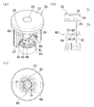
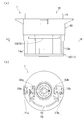
- FIG. 1A and 1B show a support for a cup holder provided with a locking device according to an embodiment of the present invention, wherein FIG. 1A is a plan view seen from above, and FIG. .
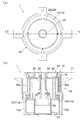
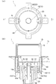
- the state in which the cup holder provided with the locking device according to the embodiment of the present invention is in operation is shown, (a) is an internal perspective view, (b) is a CC partial cross-sectional arrow view in (c), (C) is a plane perspective view.
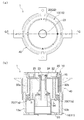
- the state after the operation of the cup holder provided with the locking device according to the embodiment of the present invention is shown, (a) is an internal perspective view, (b) is a DD partial sectional view in (c), (C) is a plane perspective view.
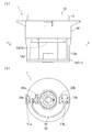
- movement of the cup holder provided with the locking device concerning embodiment of this invention is shown, (a) is a top view, (b) is EE side surface sectional drawing of (a).
- movement of the cup holder provided with the locking device concerning embodiment of this invention is shown, (a) is a top view, (b) is II side sectional drawing of (a).
- movement of the cup holder provided with the locking device concerning embodiment of this invention is shown, (a) is a side view, (b) is JJ plane sectional drawing of (a).
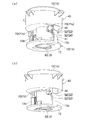
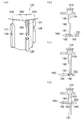
- the modification and operation state of the locking device concerning the embodiment of the present invention are shown, (a) is a perspective view of a part of the locking device, (b) is the partial section schematic diagram showing the state before operation, c) (d) is a schematic partial cross-section showing the operating state.
- the locking device according to the embodiment of the present invention locks a moving moving body at a specific position or releases the lock, and is used for various mechanisms.
- This embodiment which is an example thereof, is a configuration when the locking device is incorporated in a cup holder provided in a console of an automobile (not shown), for example.
- the locking device concerning the embodiment of the present invention is explained based on a drawing with a cup holder.
- FIG. 1 and 2 show a state in which the cup holder 1 incorporating the locking device is attached to the console 2, FIG. 1 shows a state before the cup holder 1 is used, and FIG. The holder 1 is in a used state.
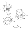
- FIG. 3 shows the appearance of the components of the cup holder 1 in which the locking device is incorporated.
- FIG. 4 shows the cup holder 1 in an exploded state.
- the cup holder 1 includes a first member 10 that moves up and down relatively and a second member 20 as a moving body supported by a support body 40. However, it is a structure which can move to the direction which mutually approaches or leaves
- the members 10 and 20 are arranged flat on the same plane as the surface of the console 2 and are accommodated inside the console 2.
- the first member 10 protrudes from the surface of the console 2 and the second member 20 is drawn into the console 2.
- the upward direction is the upward direction
- the downward direction is the downward direction
- the direction orthogonal to the vertical direction is the lateral direction.
- the position of each member 10, 20 in a state of non-use (see reference numeral Y 1 in see FIG. 12 (b)) and the non-use position as the first position, the position of the members 10, 20 in the state in use and a use position Y 2 as a second position (see symbol Y 2 in FIG. 16 (b)).
- the cup holder 1 can move the first member 10 and the second member 20, and the members 10 and 20 between the non-use position Y 1 and the use position Y 2.
- a support 40 for supporting the a locking member 60 for locking the second member 20 to the support member 40 is supported with a second member 20 in the non-use position Y 1, a first member 10 and second member 20 It is comprised from the interlocking member 70 to be interlocked.
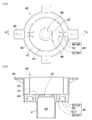
- FIG. 5 shows a plane and a cross section of the support 40.
- the support body 40 includes a lower cylindrical portion 41 formed in a cylindrical shape, and a circle that is connected to the peripheral edge of the upper end of the lower cylindrical portion 41 and expands toward the side. It is comprised from the cyclic
- the support bottom portion 44 is formed with a locking rod portion 48 protruding upward from the upper surface.
- the lower cylinder part 41 has a retaining part 42 formed inside the periphery of the upper end.
- the retaining portion 42 protrudes inward and is formed in an annular shape.
- the accommodation hole 43 which is the inner side of the lower cylinder part 41 penetrates up and down.
- the outer upper cylinder portion 45 is raised upward from the circumferential edge of the support bottom 44 and is formed with a plurality of attachment portions 46 extending from the upper circumferential edge to the side.
- the attachment portions 46 are arranged in four directions at intervals of about 90 degrees with respect to the central axis of the support body 40.
- the inner upper tube portion 47 is formed to have a smaller diameter than the outer upper tube portion 45, is disposed inside the outer upper tube portion 45, and is formed to have a larger diameter than the lower tube portion 41.
- the support body bottom portion 44 is formed with an interlocking member accommodating portion 49 on the lower surface on the side of the lower cylinder portion 41.
- the interlocking member accommodating portions 49 are a pair, and are arranged at an interval of about 180 degrees with respect to the central axis of the support body 40. Moreover, the interlocking member accommodating part 49 protrudes toward the downward direction, and the interlocking part support part 50 and the rack accommodating hole 52 are formed inside.
- the interlocking part support part 50 is formed with an interlocking part support hole 51 penetrating in a direction orthogonal to the vertical direction.
- the rack accommodation hole 52 passes through the support bottom 44 in the vertical direction.
- the rack housing hole 52 includes an outer housing hole 53 disposed between the inner upper tube portion 47 and the outer upper tube portion 45, and an inner housing hole disposed between the inner upper tube portion 47 and the lower tube portion 41. 54.
- the first member 10 is composed of a first member main body 11 and an accommodation support 15.
- the first member main body 11 is composed of a first member bottom 12 formed in a disk shape, and first racks 13a and 13b raised upward from the periphery of the first member bottom 12. Yes.
- the first member bottom 12 has a passage hole 14 through which the second member 20 passes in the center.
- the first racks 13 a and 13 b are a pair, and are arranged at an interval of about 180 degrees with respect to the central axis of the support body 40.
- the first racks 13a and 13b face each other, and teeth are formed on the sides facing each other.
- the container support 15 is formed in a cylindrical shape and is connected to the upper ends of the first racks 13a and 13b.
- the accommodated item support unit 15 is sized to accommodate an accommodated item (not shown) such as a beverage container, and supports the side surface of the container.
- the second member 20 includes a second member main body 21 and a second member driving portion 33.
- the second member main body 21 includes a seat surface portion 22 formed in a disk shape, an operation portion 23 formed in the center of the seat surface portion 22, and a coil spring for operation formed on a lower surface of the operation portion 23. 24 (refer FIG. 12), It is comprised from the 2nd racks 32a and 32b extended toward the downward direction from the peripheral edge of the seat surface part 22.
- the second member drive unit 33 is attached to the lower end of the drive coil spring 34 as a second biasing member through which the release member 25 is passed, and is connected to the lower end of the release member 25.
- a cylindrical or columnar second member bottom 35 is formed.
- the release member 25 has a locking overhang portion 27 and a contact overhang portion 29 formed on the side surface of a column or cylindrical column portion 26 extending vertically.
- the locking overhang portions 27 are a pair, and are arranged at an interval of about 180 degrees with respect to the central axis of the support column portion 26.
- the locking overhang portion 27 is a bar-like shape extending vertically on the side surface of the support column portion 26 and is extended toward the side, and a locking portion 28 is formed in part.
- the locking part 28 is a notch.
- the contact overhang portions 29 are a pair, and are arranged at an interval of about 180 degrees with respect to the central axis of the support column portion 26.
- the abutting overhanging portion 29 is a bar-like shape extending up and down on the side surface of the support column portion 26 and overhanging to the side, and a gap 30 is formed in a part thereof and is vertically divided.
- a contact portion 31 is formed on the lower end surface of the contact overhang portion 29 in the gap 30.
- the locking overhanging portion 27 and the contact overhanging portion 29 are arranged at an interval of about 90 degrees with respect to the central axis of the support column portion 26.
- locking part 28 and the contact part 31 are arrange
- the overhang portions 27 and 29 are spaced apart from each other by about 90 degrees with respect to the central axis of the column portion 26 and are alternately arranged in the circumferential direction.
- the second racks 32a and 32b are a pair, and are arranged at an interval of about 180 degrees with respect to the central axis of the support 40.
- the second racks 32a and 32b face each other, and teeth are formed on the side opposite to the side facing each other.
- the seat surface portion 22 has a size on which the container is placed.
- FIG. 6 shows the appearance of the lock member 60.
- the lock member 60 is a ring, a pair of passage groove portions 61 and a pair of locking groove portions 62 are formed on the inner peripheral surface, and a plurality of protrusions 63 are formed on the outer peripheral surface.
- a locking projection 64 is formed on the upper surface.
- the pair of passage grooves 61 are formed so as to be spaced apart from each other by about 180 degrees with respect to the central axis of the lock member 60.
- the locking groove 62 is also a pair, and is formed with an interval of about 180 degrees with respect to the central axis of the lock member 60.
- the grooves 61 and 62 are spaced apart from each other by about 90 degrees with respect to the central axis of the lock member 60 and are alternately arranged in the circumferential direction.
- a first flat surface portion 65 and a second flat surface portion 69 as a flat surface portion are formed between the passage groove portion 61 and the locking groove portion 62.
- the flat portions 65 and 69 protrude toward the center of the lock member 60 between the groove portions 61 and 62.
- the passage groove portion 61 is formed with a deceleration inclined surface portion 66 as a deceleration portion at the boundary with the first flat surface portion 65.
- the deceleration inclined surface portion 66 is inclined in the passage groove portion 61 by gradually projecting in the circumferential direction from the upper surface to the lower surface of the lock member 60.
- the plane portion 65 and the passage groove portion 61 are formed on both sides of the deceleration inclined surface portion 66 in the circumferential direction.
- the deceleration inclined surface portion 66 is a member having a frictional force that generates a predetermined sliding resistance.
- the locking groove 62 is formed with a locking inclined surface 67 at the boundary with the second flat surface 69.
- the locking inclined surface portion 67 is inclined by gradually protruding in the circumferential direction from the upper surface to the lower surface of the locking member 60 in the locking groove portion 62.
- the second flat surface portion 69 and the locking groove portion 62 are formed on both sides of the locking inclined surface portion 67 in the circumferential direction.
- the protrusion 63 protrudes toward the side, and is formed at three positions with an interval of about 120 degrees with respect to the central axis of the lock member 60.
- the locking protrusion 64 protrudes upward, and the upper end is refracted in the circumferential direction.
- the locking projection 64 is connected to a torsion spring 68 as a first biasing member.
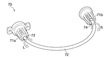
- FIG. 7 shows the external appearance of the interlocking member 70.
- the interlocking member 70 includes a plurality of connection transmission members 71a and 71b that connect the first member 10 and the second member 20, and deformation transmission that connects the connection transmission members 71a and 71b.
- the member 72 is comprised.
- the connection transmission members 71a and 71b are gears, for example, and a hole is formed in the center.
- the interlocking member 70 is configured by connecting the gears 71a and 71b via the deformation transmitting member 72 passed through the holes of the gears 71a and 71b.
- the gears 71a and 71b may be provided with a rotary damper.
- the deformation transmitting member 72 is, for example, a close coil spring or a torsion wire, and freely deforms in a non-linear manner.
- non-linear means that it is not a straight line. That is, the deformation transmission member 72 is freely bent or bent.
- the deformation transmission member 72 is compressed by the rotation of the gears 71a and 71b. If the contact coil spring is described in detail as an example, the contact coil spring is wound in a compressing direction when the gear 71a rotates in the direction of arrow L. From this, when the gear 71a rotates, the one end portion 73 of the contact coil spring is twisted in the direction of the arrow L.
- the close contact coil spring compresses and increases its rigidity, follows the one end portion 73 and twists the other end portion 74 in the direction of arrow R. At the same time, the gear 71b rotates in the direction of arrow R. This action is the same even when the deformation transmitting member 72 is a twisted wire.
- each member 10, 20, 40, 60, 70 is configured. Next, the assembly procedure of each member 10, 20, 40, 60, 70 will be described based on FIG. 4, FIG. 6, FIG. 7, and FIG. FIG. 8 shows the appearance of the cup holder 1.
- the interlocking member 70 is accommodated in the interlocking member accommodating portion 49 of the support body 40. More specifically, the gears 71a and 71b of the interlocking member 70 are accommodated in the interlocking portion support hole 51 of the interlocking member accommodating portion 49, and the deformation transmission member 72 of the interlocking member 70 is curved to make the lower cylinder portion 41 of the support 40 half a circumference. In this state, it is arranged on the outer periphery of the lower cylinder part 41.
- the lock member 60 is attached to the second member main body 21 of the second member 20. Specifically, the lock member 60 is passed through the release member 25 of the second member main body 21, and the locking inclined surface portion 67 of the lock member 60 is locked to the lock portion 28 of the lock overhang portion 27 of the release member 25. Then, the contact portion 31 of the contact overhang portion 29 of the release member 25 is brought into contact with the first flat surface portion 65 of the lock member 60.
- the second member main body 21 and the second member driving portion 33 are attached to the support 40 from above and below. More specifically, the release member 25 is passed through the accommodation hole 43 of the support body 40 from above, and the protrusion 63 of the lock member 60 is disposed on the retaining portion 42 of the support body 40, so The leading ends of the second racks 32 a and 32 b are passed through the inner accommodation hole 54 of the interlocking member accommodation portion 49.
- the lock member 60 is rotatable in the circumferential direction at the retaining portion 42.
- the second racks 32a and 32b are meshed with the gears 71a and 71b.
- the torsion spring 68 is connected to the locking bar portion 48 of the support bottom portion 44 of the support body 40.
- the second member driving portion 33 is passed through the accommodation hole 43 from below, and the second member bottom portion 35 is at the lower end of the release member 25 in a state where the driving coil spring 34 is in contact with the retaining portion 42 and compressed. Connected.
- the accommodation support 15 and the first member main body 11 are attached to the support 40 from above and below. More specifically, the front end portions of the first racks 13 a and 13 b of the first member main body portion 11 are passed from below to the outer receiving hole 53 of the interlocking member receiving portion 49, and the second hole is passed through the passage hole 14 of the first member bottom portion 12. A member bottom 35 is disposed. The first racks 13a and 13b are engaged with the gears 71a and 71b. Further, the stored matter support portion 15 is passed between the outer upper tube portion 45 and the inner upper tube portion 47 from above and connected to the upper ends of the first racks 13a and 13b.
- the interlocking member 70 is disposed inside the accommodation support 15 and outside the release member 25 (see FIG. 12B).
- the locking device of the present embodiment is realized by the release member 25, the lock member 60, and the second member driving unit 33. Further, an interlocking mechanism is realized by the interlocking member 70, the first racks 31a and 31b, and the second racks 32a and 32b.
- the second member 20 is the state of the locking device when moving from a non-use position Y 1 in the use position Y 2 is shown in the cup holder 1.
- Figure 9 shows a state where the second member 20 locking device is activated at the non-use position Y 1 is locked, and FIG. 10, the way the lock is released state, and FIG. 11, The state immediately after the lock is released is shown.
- the locking inclined surface portion 67 of the locking member 60 is locked to the locking portion 28 of the locking overhanging portion 27 of the release member 25, and
- the contact portion 31 of the contact overhang portion 29 of the release member 25 is in contact with the first flat surface portion 65.
- the second member 20 is biased downward toward the use position Y 2 by the driving coil spring 34 compressed.
- the torsion spring 68 is in a state where no external force is applied.
- the deceleration inclined surface portion 66 and the contact portion 31 are The torsion spring 68 may be urged in the direction of leaving. That is, in FIG. 9C, the lock member 60 may be biased counterclockwise.
- the locking member 60, second member 20 is in the part of the process of moving to the use position Y 2, decelerated reached immediately from just before the lock is released.
- the first member 10 and the second member 20 are disposed in a direction away from each other in the vertical direction. That is, the first member 10 is disposed at the lowermost end, and the second member 20 is disposed at the uppermost end. Further, the second racks 32 a and 32 b are arranged so as to face the inner peripheral surface of the storage object support portion 15. In this state, as shown in FIG. 14 and FIG. 15, when the operation portion 23 is pushed downward against the operation coil spring 24, the lock by the lock device is released, and each member is connected via the interlocking member 70. The members 10 and 20 move relatively up and down.
- the second racks 32a and 32b are lowered so that the gears 71a and 71b are rotated in the direction in which the second racks 32a and b are lowered (FIG. 14B).
- the gear 71a rotates in the direction of arrow R and the gear 71b rotates in the direction of arrow L), and the deformation transmitting member 72 also rotates in the same direction.
- the gears 71 a and 71 b are linked via the deformation transmission member 72.
- the gears 71a and 71b rotate, the first member 10 ascends together with the first racks 13a and 13b as shown in FIGS.
- the members 10 and 20 move relative to each other up and down, so that the accommodation support 15 is raised and protrudes from the surface of the console 2, and the seat surface portion 22 is drawn into the console 2, members 10, 20 are moved to the use position Y 2.
- the first racks 13 a and 13 b are disposed so as to face the outer peripheral surface of the seat surface portion 22.
- the gear 71a rotates in the direction of arrow L, so that one end 73 of the deformation transmission member 72 is twisted in the direction of arrow L.
- the deformation transmitting member 72 compresses and increases its rigidity, follows the one end portion 73, twists the other end portion 74 in the direction of arrow R, and simultaneously rotates the gear 71b in the direction of arrow R.
- the first member 10 descends substantially horizontally, at the same time the second member 20 is raised, the members 10 and 20 return to the non-use position Y 1. Note that this effect is the same even if only touched position X 2 is the accommodation object supporting section 15 is pushed pushed.
- the interlocking mechanism and the locking device operate together with the cup holder 1.
- the locking member 60 is a ring, and a pair of passage groove portions 61 and a pair of locking groove portions 62 are formed on the inner peripheral surface.
- the passage groove portion 61 is formed with a deceleration inclined surface portion 66 at the boundary with the first flat surface portion 65.
- the locking member 60 has a locking projection 64 formed on the upper surface, and a torsion spring 68 is connected thereto.
- the release member 25 of the second member 20 has a contact overhang portion 29 formed on the side surface of the column portion 26.
- the abutting overhanging portion 29 is a bar-like shape extending vertically on the side surface of the support column portion 26 and overhanging to the side, and the abutting portion 31 is formed on the lower end surface of the gap 30.
- the lock member 60 is passed through the release member 25, and the contact portion 31 of the release member 25 contacts the first flat surface portion 65 of the lock member 60.
- the lock member 60 rotates in the circumferential direction against the torsion spring 68 as shown in FIGS. 9 and 10.
- the lock member 60 rotates, the first flat surface portion 65 slides with respect to the contact portion 31, and further, the lock member 60 continues to rotate and the deceleration inclined surface portion 66 slides with respect to the contact portion 31.
- the restoring force of the driving coil spring 34 acts to push the second member bottom portion 35 downward, and the contact portion 31 gradually slides along the deceleration inclined surface portion 66. While passing through the passage groove 61.
- releasing member 25 is lowered through the locking member 60, second member 20 is moved to the use position Y 2.
- the cup holder 1 that can realize a smooth operation and can give a high-class impression to the occupant. Moreover, since it is not necessary to buffer the operation of the second member 20 using, for example, an air damper, a compact configuration can be realized.
- the deceleration inclined surface portion 66 is inclined by gradually protruding in the circumferential direction from the upper surface to the lower surface of the lock member 60 in the passage groove portion 61. Therefore, as shown in FIGS. 9 to 11, the second member 20 is decelerated and moves slowly as the contact portion 31 gradually slides along the deceleration inclined surface portion 66. Therefore, a smooth operation can be realized.
- the deceleration inclined surface portion 66 is a member having a frictional force that generates a predetermined sliding resistance. That is, the second member 20 is decelerated and moved slowly by the frictional resistance caused by the sliding between the deceleration inclined surface portion 66 and the contact portion 31. Therefore, a smooth operation can be realized.
- the second member driving portion 33 of the second member 20 is provided with the driving coil spring 34, and as shown in FIGS. 12 and 16, the second member 20 is biased downwardly toward the use position Y 2 by the driving coil spring 34 compressed. Therefore, it is possible to move the second member 20 to reliably use position Y 2.
- the present invention may be the following embodiments in addition to the above-described embodiment.
- the deceleration inclined surface portion 66 is a member having a frictional force that generates a predetermined sliding resistance.
- the contact portion generates a predetermined sliding resistance.
- a member having a frictional force may be used.
- the lock member 60 rotates in the circumferential direction with respect to the second member 20, but the present invention has a configuration in which the second member rotates with respect to the lock member as another configuration. May be.
- the first urging member is provided in the release member, and the release member is urged by the first urging member in a direction to separate the deceleration inclined surface portion and the contact portion.
- the first urging member is the torsion spring 68
- the second urging member and the operation coil spring are the coil springs 24 and 34.
- the present invention can be realized as other configurations if the same action can be realized. These may be coil springs, torsion springs, leaf springs, and the like.
- This embodiment has the drive spring 34 which is compressed second member 20 is urged downward toward the use position Y 2, the present invention provides, as another configuration, the second member by elongated drive spring May be pulled downward toward the use position.
- the drive coil spring 34 is provided, but the present invention may be configured such that the drive coil spring is not provided and the second member is lowered by its own weight as another configuration.
- the release member 25 of the second member 20 has a single contact portion 31 formed on the locking portion 28, but the present invention has a plurality of contact portions as a modification. It may be.
- FIG. 18 shows a modified example of the locking device and the state of the locking member 160 when the second member 20 moves.
- the contact overhang portion 129 is formed with a first contact portion 181 with the lower end overhanging in the circumferential direction of the column portion 126. Further, the protruding portion 129 is formed with a raised portion 180 at a position farther upward from the lock member 160 than the first contacting portion 181. The raised portion 180 projects in the circumferential direction, and a second contact portion 182 is formed on the lower end surface.
- the other configuration is the same as that of the lock member 60, and thus the description thereof is omitted.
- the first abutting portion 181 of the abutting overhanging portion 129 of the release member 125 is abutted against the first flat surface portion 165 of the locking member 160. ing.
- the release member 125 is lowered and the lock member 160 is moved in the circumferential direction against the torsion spring.
- the flat surface portion 165 slides with respect to the first contact portion 181, and the lock member 160 continues to rotate and the deceleration inclined surface portion 166 slides with respect to the first contact portion 181.
- the release member 125 After the first abutting portion 181 passes through the passage groove portion 161, as shown in FIG. 18D, the release member 125 further descends, and the deceleration inclined surface portion 166 is against the torsion spring and the second inclined surface portion 166 is applied. Slide against the contact portion 182.
- the lock member 160 is actuated by a restoring force due to the torsion spring when rotating in the circumferential direction, and further, a frictional force due to sliding between the deceleration inclined surface portion 166 and the first contact portion 181 acts. Further, since the frictional force and the deceleration slope portion 166 due to sliding between the second contact portion 182 acts, locking member 160, the part of the process of the second member 20 is moved to the use position Y 2, locks Decelerate from just before the release to immediately after. Therefore, a smooth operation can be realized.
- the structure which a 2nd member rotates with respect to a lock member may be sufficient.
- the first urging member is provided in the release member, and the release member is urged by the first urging member in a direction to separate the deceleration inclined surface portion and the contact portion.
- the interlocking member 70 includes a plurality of gears 71 a, b and a deformation transmission member 72 that connects the gears 71 a, b to each other.
- the gears 71a and 71b are connected to each other through a deformation transmission member 72 that is passed through the holes of the gears 71a and 71b.
- the deformation transmission member 72 is a close-contact coil spring, a torsion wire, or the like, and can be freely bent or bent. Therefore, the layout of the interlocking member 70 is free, and the layout can be designed flexibly. Furthermore, the interlocking member 70 can be configured with a small number of parts.
- the first member 10 is the first member 10.
- the rack 13a is lowered slightly earlier than the first rack 13b, but the first rack 13b is also lowered following immediately. Specifically, as the first rack 13a is lowered, the gear 71a rotates in the direction of arrow L, so that one end 73 of the deformation transmission member 72 is twisted in the direction of arrow L.
- the deformation transmitting member 72 compresses and increases its rigidity, follows the one end portion 73, twists the other end portion 74 in the direction of arrow R, and simultaneously rotates the gear 71b in the direction of arrow R.
- the first member 10 descends substantially horizontally. That is, since the gear 71a rotates through the racks 13a and 32a and the deformation transmitting member 72 is twisted to rotate the gear 71b, the gears 71a and 71b are interlocked almost simultaneously, and the racks 13b and 32b are also interlocked. . Therefore, the first member 10 or the second member 20 can be raised and lowered quickly and stably.
- the deformation transmitting member 72 is a close contact coil spring or a twisted wire, and can be freely bent or bent, so that the layout of the interlocking member 70 can be designed flexibly.
- the first member 10 is provided with the accommodation support portion 15 formed in a cylindrical shape, and the seat surface portion 22 formed in a disk shape is the first.
- Two members 20 are provided. Further, in the non-use position Y 1, the second rack 32a facing the inner peripheral surface of the accommodation object supporting portion 15, b is disposed in the use position Y 2, a first rack 13a on the outer periphery of the seat portion 22, b Is arranged.
- the interlocking member 70 is disposed on the inner side of the accommodation support 15 and on the outer side of the release member 25.
- each rack 13a, b, 32a is the seat surface portion 22 together with the contained goods support 15 via the b rises and descends, and the first member 10 and second member 20 is moved to the use position Y 2 . Therefore, the stored item can be placed on the seat surface portion 22 and appropriately supported by the stored item support unit 15.
- interlocking mechanism may have the following configuration.
- the interlocking mechanism is configured such that when the first member 10 is lowered, the deformation transmission member 72 is twisted and compressed.
- the deformation transmission member 72 is twisted and compressed. It may be a configuration. Referring to FIG. 12B, in this configuration, as the second rack 32a is lowered, the gear 71a rotates clockwise, so that the deformation transmission member 72 is also twisted in the same direction.
- the deformation transmitting member 72 compresses and increases its rigidity, follows the one end portion, twists the other end portion in the counterclockwise direction, and simultaneously rotates the gear 71b counterclockwise.
- the second member 20 descends substantially horizontally, and increases the first member 10 at the same time, the members 10, 20 are disposed in the use position Y 2. That is, since the gear 71a rotates and the deformation transmitting member 72 is twisted to rotate the gear 71b, the gears 71a and 71b are interlocked almost simultaneously.
- Interlocking mechanism is a first member 10 and second member 20 is configured to move to the non-use position Y 1 or use position Y 2, as another example, only the first member second member is fixed
- a configuration in which the first member is lifted and moved to the use position, or a configuration in which only the second member is lowered and moved to the use position may be employed.
- the rack is provided only on one of the first member and the second member.
- connection transmission member is composed of two gears 71a and 71b, but as another example, it may be composed of three or more gears. In this configuration, a plurality of racks are provided on the first member and the second member according to the number of gears.
- the coupling transmission member is the gears 71a and 71b, but as another example, the coupling transmission member may be configured by a link mechanism. In this configuration, the interlocking member and the second member are connected via the link mechanism.
Landscapes
- Engineering & Computer Science (AREA)
- Mechanical Engineering (AREA)
- Physics & Mathematics (AREA)
- Thermal Sciences (AREA)
- Transportation (AREA)
- General Engineering & Computer Science (AREA)
- Passenger Equipment (AREA)
- Vehicle Step Arrangements And Article Storage (AREA)
- Braking Arrangements (AREA)
Abstract
滑らかな動作を実現することができ、また、乗員に対して高級な印象を与えるカップホルダを実現することができるロック装置を提供する。 【解決手段】ロック装置は、第一平面部65と、第二部材20が使用位置Y2に移動する過程の少なくとも一部を減速させる減速傾斜面部66とが形成されたロック部材60、不使用位置Y1において第一平面部65と当接する当接部31が形成された解除部材25、第二部材20が移動する方向を中心としてロック部材60が回転する方向において減速傾斜面部66と当接部31とを離す方向に付勢するトーションバネ68、が備えられ、解除部材65が下降してロックが解除されることで、ロック部材60がトーションバネ68に抗して回転すると共に減速傾斜面部66と当接部31とが摺動した後、当接部31が通過溝部61を通過して第二部材20が不使用位置Y2に移動する。
Description
本発明は、移動体を特定の位置でロックし、また、ロックを解除するロック装置に関するものである。
従来、ロック装置は、例えば自動車のコンソールに備えられたカップホルダなどに用いられている。下記特許文献1に記載されたカップホルダは、円形状のカップトレイと円環状の規制体とが、ラック・ピニオンを介して連結された構成である。カップホルダが不使用の状態では、カップトレイおよび規制体は、コンソールの内側に収められてロックされている。乗員によって操作ボタンが押されてロックが解除されると、自重によってカップトレイが下降すると共に規制体が上昇し、飲料などの容器を収容することができる状態となる。カップトレイが下降する動作は、エアダンパによって緩衝される。一方、規制体が押し下げられると、カップトレイが押し上げられて元の状態に戻る。
しかし、上記したカップホルダは、ロックが解除されるのと同時にカップトレイが下降することから、唐突に動作するため、乗員に対して低級な印象を与える場合がある。また、カップトレイが下降する動作を緩衝するために、エアダンパが必要であるため、部品数が増え、さらに、エアダンパの配置位置の確保が必要となる。
本発明は、この様な実情に鑑みて提案されたものである。すなわち、滑らかな動作を実現することができ、また、乗員に対して高級な印象を与えるカップホルダを実現することができるロック装置の提供を目的とする。
上記目的を達成するために、本発明に係るロック装置は、第一位置または第二位置に配置される移動体と、この移動体を前記第一位置でロックするロック部材とが備えられたロック装置であって、前記ロック部材は、前記移動体が前記第二位置に移動する過程の少なくとも一部を減速させる減速部が備えられ、ロックが解除されることで、前記移動体が前記減速部によって減速されて前記第二位置に移動する、ことを特徴とする。
本発明に係るロック装置は、前記第一位置において前記ロック部材と当接する当接部が、前記移動体に備えられ、前記移動体が移動する方向と交差する方向において前記減速部と前記当接部とを離す方向に付勢する第一付勢部材が、前記移動体または前記ロック部材に備えられ、ロックが解除されることで、前記移動体と前記ロック部材とが前記第一付勢部材に抗する方向に相対的に移動すると共に、前記第一付勢部材に抗して前記減速部と前記当接部とが摺動して前記移動体が前記第二位置に移動する、ことを特徴とする。
本発明に係るロック装置は、前記第一位置において前記ロック部材と当接する第一当接部と、前記第一位置における前記第一当接部よりも前記ロック部材から離れた位置に形成された第二当接部とが、前記移動体に備えられ、前記移動体が移動する方向と交差する方向において前記減速部と前記第一当接部および前記第二当接部とを離す方向に付勢する第一付勢部材が、前記移動体または前記ロック部材に備えられ、ロックが解除されることで、前記移動体と前記ロック部材とが前記第一付勢部材に抗する方向に相対的に移動すると共に、前記第一付勢部材に抗して前記減速部と前記第一当接部とが摺動した後、前記第一付勢部材に抗して前記減速部と前記第二当接部とが摺動して前記移動体が前記第二位置に移動する、ことを特徴とする。
本発明に係るロック装置は、前記ロック部材は、前記減速部が傾斜面部であり、この傾斜面部の両側にそれぞれ形成された平面部と通過溝部とが備えられ、前記平面部に前記当接部が当接することで前記移動体が前記第一位置でロックされ、ロックが解除されることで、前記ロック部材が移動すると共に前記傾斜面部が前記当接部に移動して前記当接部と摺動した後、前記当接部が前記通過溝部を通過して前記移動体が前記第二位置に移動する、
ことを特徴とする。
ことを特徴とする。
本発明に係るロック装置は、前記減速部は、摺動抵抗を生じさせる摩擦部材である、ことを特徴とする。
本発明に係るロック装置は、前記移動体は、収容物が載置される座面部が備えられ、前記ロック部材は、円環状に形成されて前記移動体が通され、前記ロック部材が支持されると共に前記移動体が移動可能に支持された支持体が備えられ、ロックが解除されることで、前記ロック部材が円周方向に回転すると共に前記移動体が前記ロック部材を通って前記第二位置に移動する、ことを特徴とする。
本発明に係るロック装置は、前記移動体を前記第二位置に向けて付勢する第二付勢部材が備えられた、ことを特徴とする。
本発明に係るロック装置は上記した構成である。すなわち、移動体が減速部によって減速されるため、移動体がゆっくりと移動する。したがって、滑らかな動作を実現することができ、乗員に対して高級な印象を与えるカップホルダを実現することができる。また、移動体の動作を緩衝するための部材を必要としないため、コンパクトな構成を実現することができる。
本発明に係るロック装置は、第一位置においてロック部材と当接する当接部が、移動体に備えられ、移動体が移動する方向と交差する方向において減速部と当接部とを離す方向に付勢する第一付勢部材が、移動体またはロック部材に備えられ、ロックが解除されることで、移動体とロック部材とが第一付勢部材に抗する方向に相対的に移動すると共に、第一付勢部材に抗して減速部と当接部とが摺動して移動体が第二位置に移動する。すなわち、減速部と当接部との摺動による抵抗が作用することに加えて、第一付勢部材の反発力がロック部材に作用することで、移動体が減速されてゆっくりと移動する。したがって、滑らかな動作を実現することがきる。
本発明に係るロック装置は、第一位置においてロック部材と当接する第一当接部と、第一位置における第一当接部よりもロック部材から離れた位置に形成された第二当接部とが、移動体に備えられ、移動体が移動する方向と交差する方向において減速部と第一当接部および第二当接部とを離す方向に付勢する第一付勢部材が、移動体またはロック部材に備えられ、ロックが解除されることで、移動体とロック部材とが第一付勢部材に抗する方向に相対的に移動すると共に、第一付勢部材に抗して減速部と第一当接部とが摺動した後、第一付勢部材に抗して減速部と第二当接部とが摺動して移動体が第二位置に移動する。すなわち、減速部と第一当接部との摺動による抵抗、および、第一付勢部材の反発力がロック部材に作用することによる抵抗に加えて、減速部と第二当接部との摺動による抵抗が作用することで、移動体が更に減速されてゆっくりと移動する。したがって、滑らかな動作を実現することがきる。
本発明に係るロック装置によれば、ロック部材は、減速部が傾斜面部であり、この傾斜面部の両側にそれぞれ形成された平面部と通過溝部とが備えられ、平面部に当接部が当接することで移動体が第一位置でロックされ、ロックが解除されることで、ロック部材が移動すると共に傾斜面部が当接部に移動して当接部と摺動した後、当接部が通過溝部を通過して移動体が第二位置に移動する。すなわち、移動体は、当接部が傾斜面部に沿って徐々に摺動することで、減速されてゆっくりと移動する。したがって、滑らかな動作を実現することがきる。
本発明に係るロック装置によれば、減速部は、摺動抵抗を生じさせる摩擦部材である。すなわち、減速部と当接部との摺動による摩擦抵抗により、移動体が減速されてゆっくりと移動する。したがって、滑らかな動作を実現することがきる。
本発明に係るロック装置によれば、移動体は、収容物が載置される座面部が備えられ、ロック部材は、円環状に形成されて移動体が通され、ロック部材が支持されると共に移動体が移動可能に支持された支持体が備えられ、ロックが解除されることで、ロック部材が円周方向に回転すると共に移動体がロック部材を通って第二位置に移動する。すなわち、ロック部材が移動体に通されているため、コンパクトな構成を実現することができる。また、収容物を座面部に載置することができる。
本発明に係るロック装置は、移動体を第二位置に向けて付勢する第二付勢部材が備えられている。この構成により、移動体を確実に第二位置に移動させることができる。
本発明の実施形態に係るロック装置は、移動する移動体を特定の位置でロックし、または、ロックを解除するものであり、様々な機構に利用される。その一例である本実施形態は、ロック装置が、例えば自動車(図示省略)のコンソールに備えられたカップホルダに組み込まれた場合の構成である。以下に、本発明の実施形態に係るロック装置をカップホルダと共に図面に基づいて説明する。
図1および図2は、ロック装置が組み込まれたカップホルダ1がコンソール2に取り付けられた状態が示され、図1は、カップホルダ1が使用される前の状態であり、図2は、カップホルダ1が使用されている状態である。図3は、ロック装置が組み込まれたカップホルダ1の構成部材の外観が示されている。図4は、カップホルダ1が分解されて示されている。
図1および図2に示されているとおり、カップホルダ1は、互いが相対的に昇降する第一部材10および移動体としての第二部材20が支持体40に支持され、各部材10,20が、互いに近づく方向または離れる方向に移動可能な構成である。図1に示されているとおり、カップホルダ1は、不使用の場合、各部材10,20がコンソール2の表面と同一平面上において平坦に配置され、コンソール2の内側に収容されている。一方、図2に示されているとおり、使用中の場合、コンソール2の表面から第一部材10が突出すると共に、第二部材20がコンソール2の内側に引き込まれる。なお、以下の説明では、各部材10,20の移動方向において、上昇する方向を上方とし、下降する方向を下方とし、上下方向と直交する方向を側方とする。また、不使用の状態における各部材10,20の位置を、第一位置としての不使用位置とし(図12(b)の符号Y1参照)、使用中の状態における各部材10,20の位置を、第二位置としての使用位置Y2とする(図16(b)の符号Y2参照)。
図3および図4に示されているとおり、カップホルダ1は、第一部材10および第二部材20と、各部材10,20を不使用位置Y1と使用位置Y2との間で移動可能に支持する支持体40と、この支持体40に第二部材20と共に支持されて第二部材20を不使用位置Y1でロックするロック部材60と、第一部材10と第二部材20とを連動させる連動部材70とから構成されている。
ここで、支持体40を図4および図5に基づいて説明する。図5は、支持体40の平面および断面が示されている。
<支持体40>
図4および図5に示されているとおり、支持体40は、円筒状に形成された下筒部41と、この下筒部41の上端の周縁に連接されて側方に向けて広がった円環状の支持体底部44と、この支持体底部44の上面に形成されて同心円上に配置された円筒状の外側上筒部45および内側上筒部47とから構成されている。支持体底部44は、上面から上方に向けて突出した係止棒部48が形成されている。
図4および図5に示されているとおり、支持体40は、円筒状に形成された下筒部41と、この下筒部41の上端の周縁に連接されて側方に向けて広がった円環状の支持体底部44と、この支持体底部44の上面に形成されて同心円上に配置された円筒状の外側上筒部45および内側上筒部47とから構成されている。支持体底部44は、上面から上方に向けて突出した係止棒部48が形成されている。
下筒部41は、上端の周縁の内側に留部42が形成されている。この留部42は、内側に向けて突出して環状に形成されている。下筒部41の内側である収容孔43は、上下に貫通している。外側上筒部45は、支持体底部44の円周縁から上方に向けて立ち上げられ、上端の円周縁から側方に向けて伸びた複数の取付部46が形成されている。取付部46は、支持体40の中心軸に対して互いに約90度の間隔が空けられて四方に配置されている。内側上筒部47は、外側上筒部45よりも直径が小さく形成されると共に外側上筒部45よりも内側に配置され、かつ、下筒部41よりも直径が大きく形成されている。
支持体底部44は、下面において下筒部41の側方に連動部材収容部49が形成されている。この連動部材収容部49は、一対であり、支持体40の中心軸に対して互いに約180度の間隔が空けられて配置されている。また、連動部材収容部49は、下方に向けて突出し、連動部支持部50とラック収容孔52とが内側に形成されている。連動部支持部50は、上下方向と直交する方向に貫通した連動部支持孔51が形成されている。ラック収容孔52は、支持体底部44を上下に貫通している。ラック収容孔52は、内側上筒部47と外側上筒部45との間に配置された外側収容孔53と、内側上筒部47と下筒部41との間に配置された内側収容孔54とから構成されている。
次に、第一部材10および第二部材20を図3および図4に基づいて説明する。
<第一部材10>
図3および図4に示されているとおり、第一部材10は、第一部材本体部11と収容物支持部15とから構成されている。第一部材本体部11は、円板状に形成された第一部材底部12と、この第一部材底部12の周縁から上方に向けて立ち上げられた第一ラック13a,bとから構成されている。第一部材底部12は、中央に第二部材20が通る通過孔14が形成されている。第一ラック13a,bは、一対であり、支持体40の中心軸に対して互いに約180度の間隔が空けられて配置されている。第一ラック13a,bは、互いに対面し、互いが対面する側に歯が形成されている。収容物支持部15は、円筒状に形成され、第一ラック13a,bの上端に接続されている。収容物支持部15は、例えば飲料の容器などの収容物(図示省略)が収容される大きさであり、容器の側面が支持される。
図3および図4に示されているとおり、第一部材10は、第一部材本体部11と収容物支持部15とから構成されている。第一部材本体部11は、円板状に形成された第一部材底部12と、この第一部材底部12の周縁から上方に向けて立ち上げられた第一ラック13a,bとから構成されている。第一部材底部12は、中央に第二部材20が通る通過孔14が形成されている。第一ラック13a,bは、一対であり、支持体40の中心軸に対して互いに約180度の間隔が空けられて配置されている。第一ラック13a,bは、互いに対面し、互いが対面する側に歯が形成されている。収容物支持部15は、円筒状に形成され、第一ラック13a,bの上端に接続されている。収容物支持部15は、例えば飲料の容器などの収容物(図示省略)が収容される大きさであり、容器の側面が支持される。
<第二部材20>
図3および図4に示されているとおり、第二部材20は、第二部材本体部21と第二部材駆動部33とから構成されている。第二部材本体部21は、円板状に形成された座面部22と、この座面部22の中央に形成された操作部23と、円筒状に形成されて操作部23の下面に操作用コイルバネ24(図12参照)を介して連結された解除部材25と、座面部22の周縁から下方に向けて伸びた第二ラック32a,bとから構成されている。一方、第二部材駆動部33は、解除部材25が通される第二付勢部材としての駆動用コイルバネ34と、この駆動用コイルバネ34の下端に取り付けられると共に解除部材25の下端に接続される円筒状または円柱状の第二部材底部35とから構成されている。
図3および図4に示されているとおり、第二部材20は、第二部材本体部21と第二部材駆動部33とから構成されている。第二部材本体部21は、円板状に形成された座面部22と、この座面部22の中央に形成された操作部23と、円筒状に形成されて操作部23の下面に操作用コイルバネ24(図12参照)を介して連結された解除部材25と、座面部22の周縁から下方に向けて伸びた第二ラック32a,bとから構成されている。一方、第二部材駆動部33は、解除部材25が通される第二付勢部材としての駆動用コイルバネ34と、この駆動用コイルバネ34の下端に取り付けられると共に解除部材25の下端に接続される円筒状または円柱状の第二部材底部35とから構成されている。
解除部材25は、上下に伸びた円柱または円筒状の支柱部26の側面に係止張出し部27および当接張出し部29が形成されている。係止張出し部27は一対であり、支柱部26の中心軸に対して互いに約180度の間隔が空けられて配置されている。係止張出し部27は、支柱部26の側面において、上下に伸びた棒状であると共に側方に向けて張り出し、一部に係止部28が形成されている。係止部28は切欠きである。当接張出し部29は、一対であり、支柱部26の中心軸に対して互いに約180度の間隔が空けられて配置されている。当接張出し部29は、支柱部26の側面において、上下に伸びた棒状であると共に側方に向けて張り出し、一部に空隙30が形成されて上下に分断されている。空隙30における当接張出し部29の下端面に、当接部31が形成されている。係止張出し部27および当接張出し部29は、支柱部26の中心軸に対して互いに約90度の間隔が空けられて配置されている。また、係止部28と当接部31とは、上下においてほぼ同じ位置に配置されている。各張出し部27,29は、支柱部26の中心軸に対して互いに約90度の間隔が空けられ、円周方向に互い違いに配置されている。
第二ラック32a,bは一対であり、支持体40の中心軸に対して互いに約180度の間隔が空けられて配置されている。第二ラック32a,bは互いに対面し、互いが対面する側と反対側の側面に歯が形成されている。座面部22は、容器が載置される大きさである。
次に、ロック部材60を図6に基づいて説明する。図6は、ロック部材60の外観が示されている。
<ロック部材60>
図6に示されているとおり、ロック部材60は円環であり、内周面に、一対の通過溝部61と一対の係止溝部62とが形成され、外周面に複数の突起部63が形成され、上面に係止突部64が形成されている。通過溝部61は一対であり、ロック部材60の中心軸に対して互いに約180度の間隔が空けられて形成されている。一方、係止溝部62も一対であり、ロック部材60の中心軸に対して互いに約180度の間隔が空けられて形成されている。各溝部61,62は、ロック部材60の中心軸に対して互いに約90度の間隔が空けられ、円周方向に互い違いに配置されている。ロック部材60は、上面において、通過溝部61と係止溝部62との間に、平面部としての第一平面部65および第二平面部69が形成されている。換言すれば、各平面部65,69は、各溝部61,62同士の間において、ロック部材60の中心に向けて突出している。
図6に示されているとおり、ロック部材60は円環であり、内周面に、一対の通過溝部61と一対の係止溝部62とが形成され、外周面に複数の突起部63が形成され、上面に係止突部64が形成されている。通過溝部61は一対であり、ロック部材60の中心軸に対して互いに約180度の間隔が空けられて形成されている。一方、係止溝部62も一対であり、ロック部材60の中心軸に対して互いに約180度の間隔が空けられて形成されている。各溝部61,62は、ロック部材60の中心軸に対して互いに約90度の間隔が空けられ、円周方向に互い違いに配置されている。ロック部材60は、上面において、通過溝部61と係止溝部62との間に、平面部としての第一平面部65および第二平面部69が形成されている。換言すれば、各平面部65,69は、各溝部61,62同士の間において、ロック部材60の中心に向けて突出している。
通過溝部61は、第一平面部65との境界に、減速部としての減速傾斜面部66が形成されている。減速傾斜面部66は、通過溝部61において、ロック部材60の上面から下面に向かうにしたがって、徐々に円周方向に張り出すことで傾斜している。換言すれば、円周方向において、減速傾斜面部66の両側に平面部65と通過溝部61とがそれぞれ形成されている。また、減速傾斜面部66は、所定の摺動抵抗を生じさせる摩擦力を有する部材である。
係止溝部62は、第二平面部69との境界に、係止傾斜面部67が形成されている。係止傾斜面部67は、係止溝部62において、ロック部材60の上面から下面に向かうにしたがって、徐々に円周方向に張り出すことで傾斜している。換言すれば、円周方向において、係止傾斜面部67の両側に第二平面部69と係止溝部62とがそれぞれ形成されている。
突起部63は、側方に向けて突出し、ロック部材60の中心軸に対して互いに約120度の間隔が空けられて三か所に形成されている。係止突部64は、上方に向けて突出すると共に、上端が円周方向に屈折している。係止突部64は、第一付勢部材としてのトーションバネ68が接続されている。
次に、連動部材70を図7に基づいて説明する。図7は、連動部材70の外観が示されている。
<連動部材70>
図7に示されているとおり、連動部材70は、第一部材10と第二部材20とを連結する複数の連結伝達部材71a,bと、この連結伝達部材71a,b同士を連結する変形伝達部材72とから構成されている。連結伝達部材71a,bは、例えばギヤであり、中心に孔が形成されている。このギヤ71a,bの孔に通された変形伝達部材72を介してギヤ71a,b同士が連結されて連動部材70が構成されている。なお、ギヤ71a,bは、回転式ダンパーが備えられていてもよい。
図7に示されているとおり、連動部材70は、第一部材10と第二部材20とを連結する複数の連結伝達部材71a,bと、この連結伝達部材71a,b同士を連結する変形伝達部材72とから構成されている。連結伝達部材71a,bは、例えばギヤであり、中心に孔が形成されている。このギヤ71a,bの孔に通された変形伝達部材72を介してギヤ71a,b同士が連結されて連動部材70が構成されている。なお、ギヤ71a,bは、回転式ダンパーが備えられていてもよい。
変形伝達部材72は、例えば、密着コイルバネや捩りワイヤなどであり、自在に非線状に変形する。ここで、非線状とは、直線ではないことをいう。すなわち、変形伝達部材72は、自在に湾曲し、または屈曲する。変形伝達部材72は、ギヤ71a,bが回転することで圧縮する。密着コイルバネを例にして詳説すれば、密着コイルバネは、ギヤ71aが矢印Lの方向に回転した場合に、圧縮する方向に巻かれている。このことから、ギヤ71aが回転すると、密着コイルバネの一端部73が矢印Lの方向に捩れる。密着コイルバネは、圧縮すると共に剛性が高まり、一端部73に追随して他端部74が矢印Rの方向に捩れる。同時に、ギヤ71bが矢印Rの方向に回転する。なお、この作用は、変形伝達部材72が捩りワイヤであっても同様である。
上記したとおり、各部材10,20,40,60,70が構成されている。次に、各部材10,20,40,60,70の組立て手順を図4、図6、図7および図8に基づいて説明する。図8は、カップホルダ1の外観が示されている。
図4および図8において、支持体40の連動部材収容部49に連動部材70が収容される。詳説すれば、連動部材70のギヤ71a,bが連動部材収容部49の連動部支持孔51に収容され、連動部材70の変形伝達部材72が湾曲して支持体40の下筒部41を半周した状態で下筒部41の外周に配置される。
図4および図6において、第二部材20の第二部材本体部21にロック部材60が取り付けられる。詳説すれば、ロック部材60が第二部材本体部21の解除部材25に通され、ロック部材60の係止傾斜面部67が、解除部材25における係止張出し部27の係止部28に係止され、ロック部材60の第一平面部65に解除部材25における当接張出し部29の当接部31が当接される。
この状態で、図4において、第二部材本体部21と第二部材駆動部33とが上下から支持体40に取り付けられる。詳説すれば、解除部材25が、上方から支持体40の収容孔43に通されると共に、ロック部材60の突起部63が支持体40の留部42に配置され、第二部材本体部21の第二ラック32a,bの先端部が、連動部材収容部49の内側収容孔54に通される。ロック部材60は、留部42において円周方向に回転可能である。第二ラック32a,bは、ギヤ71a,bと噛み合わされる。トーションバネ68は、支持体40の支持底部44の係止棒部48に接続される。さらに、第二部材駆動部33が、下方から収容孔43に通され、駆動用コイルバネ34が留部42の下に当接して圧縮した状態で、第二部材底部35が解除部材25の下端に接続される。
次に、図4および図8において、収容物支持部15と第一部材本体部11とが上下から支持体40に取り付けられる。詳説すれば、第一部材本体部11の第一ラック13a,bの先端部が、下方から連動部材収容部49の外側収容孔53に通され、第一部材底部12の通過孔14に第二部材底部35が配置される。第一ラック13a,bは、ギヤ71a,bと噛み合わされる。さらに、収容物支持部15が、上方から外側上筒部45と内側上筒部47との間に通され、第一ラック13a,bの上端に接続される。
上記のとおり構成されたカップホルダ1では、連動部材70が、収容物支持部15の内側、かつ、解除部材25の外側に配置されている(図12(b)参照)。
このようなカップホルダ1において、本実施形態のロック装置は、解除部材25と、ロック部材60と、第二部材駆動部33とで実現される。また、連動部材70と、第一ラック31a,bと、第二ラック32a,bとから連動機構が実現される。以下、連動機構およびロック装置の作用を、カップホルダ1の動作と共に図面に基づいて説明する。図9から図11は、カップホルダ1において第二部材20が不使用位置Y1から使用位置Y2に移動する際のロック装置の状態が示されている。図9は、不使用位置Y1においてロック装置が作動して第二部材20がロックされている状態が示され、図10は、ロックが解除される途中の状態が示され、図11は、ロックが解除された直後の状態が示されている。
図9に示されているとおり、不使用位置Y1では、ロック部材60における係止傾斜面部67が、解除部材25における係止張出し部27の係止部28に係止し、ロック部材60の第一平面部65に、解除部材25における当接張出し部29の当接部31が当接されている。第二部材20は、圧縮した駆動用コイルバネ34によって使用位置Y2に向けて下方に付勢されている。その際、トーションバネ68は外力が加わっていない状態である。なお、解除部材25の中心軸と交差する方向であって、解除部材25の中心軸を中心として周回する方向であるロック部材60の円周方向において、減速傾斜面部66と当接部31とが離れる方向にトーションバネ68が付勢されていてもよい。すなわち、図9(c)において、ロック部材60が左回りに付勢されていてもよい。
この状態で、操作用コイルバネ24(図12参照)に抗して操作部23が下方に押されると、ロックが解除され、図10に示されているとおり、解除部材25が下降すると共に、ロック部材60が円周方向に回転する。詳説すれば、ロック部材60は、係止傾斜面部67が解除部材25の係止部28によって下方に押されることで、トーションバネ68に抗して円周方向に回転する。ロック部材60が回転すると、第一平面部65が当接部31に対して摺動し、更にロック部材60が回転し続けて減速傾斜面部66が当接部31に対して摺動する。
減速傾斜面部66が当接部31に対して摺動した後、図11に示されているとおり、駆動用コイルバネ34の復元力が作用することで第二部材底部35が下方に押され、当接部31が減速傾斜面部66に沿って徐々に摺動しながら通過溝部61を通過する。同時に、解除部材25がロック部材60を通って下降し、第二部材20が使用位置Y2に移動する。
上記したとおり、ロック部材60は、円周方向に回転する際にトーションバネ68による復元力が作用するため、さらに、減速傾斜面部66と当接部31との摺動による摩擦力が作用するため、ロック部材60は、第二部材20が使用位置Y2に移動する過程の一部において、ロックが解除される直前から直後に至って減速する。
次に、連動機構を図面に基づいて説明する。図12から図18は、カップホルダ1において第二部材20が不使用位置Y1から使用位置Y2に移動する際の連動機構の状態が示されている。図12および図13は、不使用位置Y1において連動機構が作動する前の状態が示され、図14および図15は、連動機構が作動している途中の状態が示され、図16および図17は、連動機構が作動した後の状態が示されている。
図12および図13に示されているとおり、不使用位置Y1では、第一部材10と第二部材20とが上下に離れる方向において配置されている。すなわち、第一部材10が最下端に配置され、第二部材20が最上端に配置されている。また、収容物支持部15の内周面と対面して第二ラック32a,bが配置されている。この状態で、図14および図15に示されているとおり、操作用コイルバネ24に抗して操作部23が下方に押されると、ロック装置によるロックが解除され、連動部材70を介して、各部材10,20が上下に相対的に移動する。詳説すれば、第二部材20が下降する際、第二ラック32a,bが下降することで、この第二ラック32a,bが下降する方向に各ギヤ71a,bが回転(図14(b)においてギヤ71aが矢印Rに回転、ギヤ71bが矢印Lに回転)すると共に、変形伝達部材72も同じ方向に回転する。換言すれば、各ギヤ71a,bは、変形伝達部材72を介して連動する。各ギヤ71a,bが回転することで、図16および図17に示されているとおり、第一ラック13a,bと共に第一部材10が上昇する。
上記のとおり各部材10,20が上下に相対的に移動することで、収容物支持部15が上昇してコンソール2の表面から突出すると共に、座面部22がコンソール2の内側に引き込まれ、各部材10,20が使用位置Y2に移動する。この状態では、座面部22の外周面と対面して第一ラック13a,bが配置されている。
使用位置Y2におけるカップホルダ1を再び不使用位置Y1に戻す場合、収容物支持部15を下方に押し込むことで、連動部材70を介して各ラック13a,b、32a,b、と共に各部材10,20が昇降する。その際、図16および図17において、押下位置X1,X2が同時に押されて収容物支持部15が押し込まれた場合、第一部材10がほぼ水平に下降すると共に第二部材20が上昇する。一方、例えば、押下位置X1のみが押されて収容物支持部15が押し込まれた場合、第一部材10は、第一ラック13aが、第一ラック13bよりも僅かに先に下降するが、瞬時に追随して第一ラック13bも下降する。詳説すれば、第一ラック13aが下降することに伴い、ギヤ71aが矢印Lの方向に回転することで、変形伝達部材72の一端部73が矢印Lの方向に捩れる。変形伝達部材72は、圧縮すると共に剛性が高まり、一端部73に追随して他端部74が矢印Rの方向に捩れ、同時に、ギヤ71bが矢印Rの方向に回転する。第一部材10は、ほぼ水平に下降し、同時に第二部材20が上昇して、各部材10,20が不使用位置Y1に戻る。なお、この作用は、押下位置X2のみが押されて収容物支持部15が押し込まれた場合であっても同様である。
上記のとおり、連動機構およびロック装置が、カップホルダ1と共に作動する。
次に、本実施形態に係るロック装置の効果を説明する。
上記したとおり、ロック装置によれば、図6に示されているとおり、ロック部材60は円環であり、内周面に、一対の通過溝部61と一対の係止溝部62とが形成されている。通過溝部61は、第一平面部65との境界に、減速傾斜面部66が形成されている。また、ロック部材60は上面に係止突部64が形成され、トーションバネ68が接続されている。一方、図4に示されているとおり、第二部材20の解除部材25は、支柱部26の側面に当接張出し部29が形成されている。当接張出し部29は、支柱部26の側面において、上下に伸びた棒状であると共に側方に向けて張り出し、空隙30における下端面に当接部31が形成されている。
図9に示されているとおり、ロック部材60が解除部材25に通され、ロック部材60の第一平面部65に解除部材25の当接部31が当接される。この構成により、解除部材25が下降すると、図9および図10に示されているとおり、トーションバネ68に抗してロック部材60が円周方向に回転する。ロック部材60が回転すると、第一平面部65が当接部31に対して摺動し、更にロック部材60が回転し続けて減速傾斜面部66が当接部31に対して摺動する。その後、図11に示されているとおり、駆動用コイルバネ34の復元力が作用することで第二部材底部35が下方に押され、当接部31が減速傾斜面部66に沿って徐々に摺動しながら通過溝部61を通過する。同時に、解除部材25がロック部材60を通って下降し、第二部材20が使用位置Y2に移動する。
すなわち、ロック部材60は、円周方向に回転する際にトーションバネ68による復元力が作用するため、さらに、減速傾斜面部66と当接部31との摺動による摩擦力が作用するため、ロック部材60は、第二部材20が使用位置Y2に移動する過程の一部において、ロックが解除される直前から直後に至って減速する。
したがって、滑らかな動作を実現することができ、乗員に対して高級な印象を与えることができるカップホルダ1を実現することができる。また、例えばエアダンパなどを用いて第二部材20の動作を緩衝することを必要としないため、コンパクトな構成を実現することができる。
特に、図6に示されているとおり、減速傾斜面部66は、通過溝部61において、ロック部材60の上面から下面に向かうにしたがって、徐々に円周方向に張り出すことで傾斜している。そのため、図9から図11に示されているとおり、第二部材20は、当接部31が減速傾斜面部66に沿って徐々に摺動することで、減速されてゆっくりと移動する。したがって、滑らかな動作を実現することがきる。
ロック装置によれば、減速傾斜面部66は、所定の摺動抵抗を生じさせる摩擦力を有する部材である。すなわち、減速傾斜面部66と当接部31との摺動による摩擦抵抗により、第二部材20が減速されてゆっくりと移動する。したがって、滑らかな動作を実現することがきる。
ロック装置によれば、図4に示されているとおり、第二部材20の第二部材駆動部33に駆動用コイルバネ34が備えられ、図12および図16に示されているとおり、第二部材20は、圧縮した駆動用コイルバネ34によって使用位置Y2に向けて下方に付勢されている。したがって、第二部材20を確実に使用位置Y2に移動させることができる。
なお、本発明は、上記した本実施形態の他、以下の実施形態であってもよい。
本実施形態は、減速傾斜面部66が、所定の摺動抵抗を生じさせる摩擦力を有する部材であるが、本発明は、他の構成として、当接部が、所定の摺動抵抗を生じさせる摩擦力を有する部材であってもよい。
本実施形態は、第二部材20に対してロック部材60が円周方向に回転する構成であるが、本発明は、他の構成として、ロック部材に対して第二部材が回転する構成であってもよい。この構成では、第一付勢部材が解除部材に備えられ、第一付勢部材によって、減速傾斜面部と当接部とを離す方向に解除部材が付勢されている。
本実施形態は、第一付勢部材がトーションバネ68、第二付勢部材および操作用コイルバネがコイルバネ24,34であるが、本発明は、他の構成として、同じ作用を実現することができれば、それぞれコイルバネ、トーションバネ、板バネなどであってもよい。
本実施形態は、圧縮した駆動用コイルバネ34によって第二部材20が使用位置Y2向けて下方に付勢されているが、本発明は、他の構成として、伸長した駆動用コイルバネによって第二部材が使用位置に向けて下方に引っ張られていてもよい。
本実施形態は、駆動用コイルバネ34が備えられているが、本発明は、他の構成として、駆動用コイルバネが備えられておらず、自重で第二部材が下降する構成であってもよい。
本実施形態では、第二部材20の解除部材25は、係止部28に単一の当接部31が形成されているが、本発明は、変形例として、複数の当接部が形成されていてもよい。ここで、本発明の実施形態に係るロック装置の変形例を図面に基づいて説明する。図18は、ロック装置の変型例、および、第二部材20が移動する際のロック部材160の状態が示されている。
図18に示されているとおり、解除部材125において、当接張出し部129は、下端が支柱部126の円周方向に張り出した第一当接部181が形成されている。また、当接張出し部129は、第一当接部181よりもロック部材160から上方に離れた位置に、隆起部180が形成されている。この隆起部180は円周方向に張り出し、下端面に第二当接部182が形成されている。なお、他の構成はロック部材60と同じであるため、説明を省略する。
このロック装置によれば、図18(b)に示されているとおり、ロック部材160の第一平面部165に、解除部材125における当接張出し部129の第一当接部181が当接されている。操作部123が下方に押されてロックが解除されると、図18(c)に示されているとおり、解除部材125が下降すると共に、トーションバネに抗してロック部材160が円周方向に回転し、平面部165が第一当接部181に対して摺動し、更にロック部材160が回転し続けて減速傾斜面部166が第一当接部181に対して摺動する。第一当接部181が通過溝部161を通過した後、図18(d)に示されているとおり、解除部材125が更に下降すると共に、トーションバネに抗して減速傾斜面部166が第二当接部182に対して摺動する。
すなわち、ロック部材160は、円周方向に回転する際にトーションバネによる復元力が作用するため、さらに、減速傾斜面部166と第一当接部181との摺動による摩擦力が作用するため、さらに、減速傾斜面部166と第二当接部182との摺動による摩擦力が作用するため、ロック部材160は、第二部材20が使用位置Y2に移動する過程の一部において、ロックが解除される直前から直後に至って減速する。したがって、滑らかな動作を実現することがきる。
なお、ロック部材に対して第二部材が回転する構成であってもよい。この構成では、第一付勢部材が解除部材に備えられ、第一付勢部材によって、減速傾斜面部と当接部とを離す方向に解除部材が付勢されている。
次に、連動機構の効果を説明する。
上記したとおり、連動機構によれば、図8に示されているとおり、連動部材70は、複数のギヤ71a,bと、このギヤ71a,b同士を連結する変形伝達部材72とから構成され、ギヤ71a,bの孔に通された変形伝達部材72を介してギヤ同士71a,bが連結されている。変形伝達部材72は、密着コイルバネや捩りワイヤなどであり、自在に湾曲し、または屈曲する。したがって、連動部材70のレイアウトが自由であり、レイアウトを柔軟に設計することができる。さらに、少ない部品で連動部材70を構成することができる。
また、図16および図17に示されているとおり、使用位置Y2において、仮に、押下位置X1のみが押されて収容物支持部15が押し込まれた場合、第一部材10は、第一ラック13aが、第一ラック13bよりも僅かに先に下降するが、瞬時に追随して第一ラック13bも下降する。詳説すれば、第一ラック13aが下降することに伴い、ギヤ71aが矢印Lの方向に回転することで、変形伝達部材72の一端部73が矢印Lの方向に捩れる。変形伝達部材72は、圧縮すると共に剛性が高まり、一端部73に追随して他端部74が矢印Rの方向に捩れ、同時に、ギヤ71bが矢印Rの方向に回転する。このことから、第一部材10は、ほぼ水平に下降する。すなわち、各ラック13a,32aを介してギヤ71aが回転すると共に変形伝達部材72が捩れてギヤ71bが回転するため、各ギヤ71a,bが、ほぼ同時に連動し、各ラック13b,32bも連動する。したがって、素早く、かつ、安定して第一部材10または第二部材20を昇降させることができる。
連動機構によれば、変形伝達部材72が、密着コイルバネまたは捩りワイヤであり、自在に湾曲し、または屈曲するため、連動部材70のレイアウトを柔軟に設計することができる。
連動機構によれば、図12および図16に示されているとおり、円筒状に形成された収容物支持部15が第一部材10に備えられ、円板状に形成された座面部22が第二部材20に備えられている。また、不使用位置Y1において、収容物支持部15の内周面と対面して第二ラック32a,bが配置され、使用位置Y2において、座面部22の外周に第一ラック13a,bが配置されている。連動部材70は、収容物支持部15の内側、かつ、解除部材25の外側に配置されている。この構成により、各ラック13a,b、32a,bを介して収容物支持部15が上昇すると共に座面部22が下降し、第一部材10と第二部材20とが使用位置Y2に移動する。したがって、収容物を座面部22に載置して収容物支持部15に適切に支持することができる。
なお、連動機構は、以下の構成であってもよい。
連動機構は、第一部材10が下降する際に、変形伝達部材72が捩れて圧縮する構成であるが、他の例として、第二部材が下降する際に、変形伝達部材が捩れて圧縮する構成であってもよい。図12(b)を参照すれば、この構成では、第二ラック32aが下降することに伴い、ギヤ71aが右回りに回転することで、変形伝達部材72も同じ方向に捩れる。変形伝達部材72は、圧縮すると共に剛性が高まり、一端部に追随して他端部が左回りの方向に捩れ、同時に、ギヤ71bが左回りに回転する。第二部材20は、ほぼ水平に下降し、同時に第一部材10が上昇して、各部材10,20が使用位置Y2に配置される。すなわち、ギヤ71aが回転すると共に変形伝達部材72が捩れてギヤ71bが回転するため、各ギヤ71a,bが、ほぼ同時に連動する。
連動機構は、第一部材10と第二部材20とが不使用位置Y1または使用位置Y2に移動する構成であるが、他の例として、第二部材が固定されて第一部材のみが上昇して使用位置に移動する構成、または、第一部材が固定されて第二部材のみが下降して使用位置に移動する構成であってもよい。この構成では、第一部材または第二部材の片方にのみラックが備えられている。
連動機構は、連結伝達部材が二つのギヤ71a,bで構成されているが、他の例として、三つ以上のギヤで構成されていてもよい。この構成では、ギヤの数に応じて複数のラックが第一部材および第二部材に備えられている。
連動機構は、連結伝達部材が各ギヤ71a,bであるが、他の例として、リンク機構で
連結伝達部材が構成されていてもよい。この構成では、リンク機構を介して連動部材と第二部材とが連結されている。
連結伝達部材が構成されていてもよい。この構成では、リンク機構を介して連動部材と第二部材とが連結されている。
以上、本発明の実施形態を詳述したが、本発明は上記実施形態に限定されるものではない。そして本発明は、特許請求の範囲に記載された事項を逸脱することがなければ、種々の設計変更を行うことが可能である。
1 カップホルダ
2 コンソール
10 第一部材
11 第一部材本体部
12 第一部材底部
13a,b 第一ラック
14 通過孔
15 収容物支持部
20 第二部材(移動体)
21 第二部材本体部
22 座面部
23,123 操作部
24 操作用コイルバネ
25,125 解除部材
26,126 支柱部
27,127 係止張出し部
28,128 係止部
29,129 当接張出し部
30,130 空隙
31 当接部
32a,b 第二ラック
33 第二部材駆動部
34 駆動用コイルバネ(第二付勢部材)
35 第二部材底部
40 支持体
41 下筒部
42 留部
43 収容孔
44 支持体底部
45 外側上筒部
46 取付部
47 内側上筒部
48 係止棒部
49 連動部材収容部
50 連動部支持部
51 連動部支持孔
52 ラック収容孔
53 外側収容孔
54 内側収容孔
60,160 ロック部材
61,161 通過溝部
62 係止溝部
63 突起部
64 係止突部
65,165 第一平面部(平面部)
66,166 減速傾斜面部(減速部)
67 係止傾斜面部
68 トーションバネ(第一付勢部材)
69 第二平面部
70 連動部材
71a,b ギヤ
72 変形伝達部材
73 一端部
74 他端部
180 隆起部
181 第一当接部
182 第二当接部
L,R 矢印
X1,X2 押下位置
Y1 不使用位置(第一位置)
Y2 使用位置(第二位置)
2 コンソール
10 第一部材
11 第一部材本体部
12 第一部材底部
13a,b 第一ラック
14 通過孔
15 収容物支持部
20 第二部材(移動体)
21 第二部材本体部
22 座面部
23,123 操作部
24 操作用コイルバネ
25,125 解除部材
26,126 支柱部
27,127 係止張出し部
28,128 係止部
29,129 当接張出し部
30,130 空隙
31 当接部
32a,b 第二ラック
33 第二部材駆動部
34 駆動用コイルバネ(第二付勢部材)
35 第二部材底部
40 支持体
41 下筒部
42 留部
43 収容孔
44 支持体底部
45 外側上筒部
46 取付部
47 内側上筒部
48 係止棒部
49 連動部材収容部
50 連動部支持部
51 連動部支持孔
52 ラック収容孔
53 外側収容孔
54 内側収容孔
60,160 ロック部材
61,161 通過溝部
62 係止溝部
63 突起部
64 係止突部
65,165 第一平面部(平面部)
66,166 減速傾斜面部(減速部)
67 係止傾斜面部
68 トーションバネ(第一付勢部材)
69 第二平面部
70 連動部材
71a,b ギヤ
72 変形伝達部材
73 一端部
74 他端部
180 隆起部
181 第一当接部
182 第二当接部
L,R 矢印
X1,X2 押下位置
Y1 不使用位置(第一位置)
Y2 使用位置(第二位置)
Claims (7)
- 第一位置または第二位置に配置される移動体と、この移動体を前記第一位置でロックするロック部材とが備えられたロック装置であって、
前記ロック部材は、前記移動体が前記第二位置に移動する過程の少なくとも一部を減速させる減速部が備えられ、
ロックが解除されることで、前記移動体が前記減速部によって減速されて前記第二位置に移動する、
ことを特徴とするロック装置。 - 前記第一位置において前記ロック部材と当接する当接部が、前記移動体に備えられ、
前記移動体が移動する方向と交差する方向において前記減速部と前記当接部とを離す方向に付勢する第一付勢部材が、前記移動体または前記ロック部材に備えられ、
ロックが解除されることで、前記移動体と前記ロック部材とが前記第一付勢部材に抗する方向に相対的に移動すると共に、前記第一付勢部材に抗して前記減速部と前記当接部とが摺動して前記移動体が前記第二位置に移動する、
ことを特徴とする請求項1に記載されたロック装置。 - 前記第一位置において前記ロック部材と当接する第一当接部と、前記第一位置における前記第一当接部よりも前記ロック部材から離れた位置に形成された第二当接部とが、前記移動体に備えられ、
前記移動体が移動する方向と交差する方向において前記減速部と前記第一当接部および前記第二当接部とを離す方向に付勢する第一付勢部材が、前記移動体または前記ロック部材に備えられ、
ロックが解除されることで、前記移動体と前記ロック部材とが前記第一付勢部材に抗する方向に相対的に移動すると共に、前記第一付勢部材に抗して前記減速部と前記第一当接部とが摺動した後、前記第一付勢部材に抗して前記減速部と前記第二当接部とが摺動して前記移動体が前記第二位置に移動する、
ことを特徴とする請求項1に記載されたロック装置。 - 前記ロック部材は、前記減速部が傾斜面部であり、この傾斜面部の両側にそれぞれ形成された平面部と通過溝部とが備えられ、
前記平面部に前記当接部が当接することで前記移動体が前記第一位置でロックされ、
ロックが解除されることで、前記ロック部材が移動すると共に前記傾斜面部が前記当接部に移動して前記当接部と摺動した後、前記当接部が前記通過溝部を通過して前記移動体が前記第二位置に移動する、
ことを特徴とする請求項1または請求項2に記載されたロック装置。 - 前記減速部は、摺動抵抗を生じさせる摩擦部材である、
ことを特徴とする請求項1から請求項4のいずれか1項に記載されたロック装置。 - 前記移動体は、収容物が載置される座面部が備えられ、
前記ロック部材は、円環状に形成されて前記移動体が通され、
前記ロック部材が支持されると共に前記移動体が移動可能に支持された支持体が備えられ、
ロックが解除されることで、前記ロック部材が円周方向に回転すると共に前記移動体が前記ロック部材を通って前記第二位置に移動する、
ことを特徴とする請求項1から請求項5のいずれか1項に記載されたロック装置。 - 前記移動体を前記第二位置に向けて付勢する第二付勢部材が備えられた、
ことを特徴とする請求項1から請求項6のいずれか1項に記載されたロック装置。
Priority Applications (3)
| Application Number | Priority Date | Filing Date | Title |
|---|---|---|---|
| KR1020187019965A KR102099031B1 (ko) | 2017-03-30 | 2018-03-12 | 로크장치 |
| DE112018001776.1T DE112018001776B4 (de) | 2017-03-30 | 2018-03-12 | Feststellvorrichtung |
| CN201880019009.3A CN110446625B (zh) | 2017-03-30 | 2018-03-12 | 锁定装置 |
Applications Claiming Priority (2)
| Application Number | Priority Date | Filing Date | Title |
|---|---|---|---|
| JP2017-068026 | 2017-03-30 | ||
| JP2017068026A JP6621436B2 (ja) | 2017-03-30 | 2017-03-30 | ロック装置 |
Publications (1)
| Publication Number | Publication Date |
|---|---|
| WO2018180397A1 true WO2018180397A1 (ja) | 2018-10-04 |
Family
ID=63675447
Family Applications (1)
| Application Number | Title | Priority Date | Filing Date |
|---|---|---|---|
| PCT/JP2018/009384 Ceased WO2018180397A1 (ja) | 2017-03-30 | 2018-03-12 | ロック装置 |
Country Status (5)
| Country | Link |
|---|---|
| JP (1) | JP6621436B2 (ja) |
| KR (1) | KR102099031B1 (ja) |
| CN (1) | CN110446625B (ja) |
| DE (1) | DE112018001776B4 (ja) |
| WO (1) | WO2018180397A1 (ja) |
Cited By (1)
| Publication number | Priority date | Publication date | Assignee | Title |
|---|---|---|---|---|
| CN109250155A (zh) * | 2018-11-21 | 2019-01-22 | 北京宇航系统工程研究所 | 一种采用弹片阻尼的空间系绳释放机构 |
Families Citing this family (6)
| Publication number | Priority date | Publication date | Assignee | Title |
|---|---|---|---|---|
| CN110356306B (zh) * | 2019-07-19 | 2020-08-18 | 北京汽车集团越野车有限公司 | 一种车用杯座装置 |
| JP7409013B2 (ja) * | 2019-10-31 | 2024-01-09 | 工機ホールディングス株式会社 | 動力工具 |
| JP7517082B2 (ja) * | 2020-10-30 | 2024-07-17 | 工機ホールディングス株式会社 | 作業機 |
| CN113304526B (zh) * | 2021-06-10 | 2024-12-03 | 中山市柠檬环境科技有限公司 | 一种滤芯座和滤芯 |
| CN113911005B (zh) * | 2021-10-26 | 2023-03-31 | 东风延锋汽车饰件系统有限公司 | 用于汽车驾驶室的升降式杯托 |
| CN115303159B (zh) * | 2022-09-14 | 2024-06-11 | 重庆创泽汽车设计有限公司 | 一种具有无级调节结构的车载杯托 |
Citations (6)
| Publication number | Priority date | Publication date | Assignee | Title |
|---|---|---|---|---|
| JPH07228181A (ja) * | 1994-02-21 | 1995-08-29 | Kanto Auto Works Ltd | 車両用カップホルダー |
| JP2005145384A (ja) * | 2003-11-19 | 2005-06-09 | Inoac Corp | 容器ホルダ |
| US20050269472A1 (en) * | 2002-10-29 | 2005-12-08 | Wagner Joerg | Drinks holder |
| JP2011020605A (ja) * | 2009-07-17 | 2011-02-03 | Toyoda Gosei Co Ltd | ロック装置 |
| JP2013107456A (ja) * | 2011-11-18 | 2013-06-06 | Toyota Auto Body Co Ltd | カップホルダ |
| JP2016060316A (ja) * | 2014-09-17 | 2016-04-25 | 明和工業株式会社 | カップホルダ |
Family Cites Families (8)
| Publication number | Priority date | Publication date | Assignee | Title |
|---|---|---|---|---|
| US5289962A (en) * | 1993-05-03 | 1994-03-01 | Chrysler Corporation | Cup holder |
| JP4596564B2 (ja) * | 2000-11-07 | 2010-12-08 | 株式会社ニフコ | カップホルダ |
| JP2009040196A (ja) * | 2007-08-08 | 2009-02-26 | Toyoda Gosei Co Ltd | カップホルダ |
| JP5723647B2 (ja) * | 2011-03-25 | 2015-05-27 | 富士重工業株式会社 | 車両用飲料容器ホルダ |
| CN104290633B (zh) * | 2013-07-19 | 2017-02-01 | 北汽福田汽车股份有限公司 | 用于车辆的杯托组件及具有其的车辆 |
| JP6071003B2 (ja) | 2014-01-21 | 2017-02-01 | 豊田合成株式会社 | カップホルダ |
| DE102014214278A1 (de) * | 2014-07-22 | 2016-01-28 | Volkswagen Aktiengesellschaft | Haltevorrichtung zum lösbaren Halten von Gegenständen |
| DE102014119428B4 (de) * | 2014-12-22 | 2017-05-24 | Dr. Ing. H.C. F. Porsche Aktiengesellschaft | Vorrichtung zur Aufnahme von Getränkebehältern |
-
2017
- 2017-03-30 JP JP2017068026A patent/JP6621436B2/ja active Active
-
2018
- 2018-03-12 DE DE112018001776.1T patent/DE112018001776B4/de active Active
- 2018-03-12 KR KR1020187019965A patent/KR102099031B1/ko active Active
- 2018-03-12 WO PCT/JP2018/009384 patent/WO2018180397A1/ja not_active Ceased
- 2018-03-12 CN CN201880019009.3A patent/CN110446625B/zh active Active
Patent Citations (6)
| Publication number | Priority date | Publication date | Assignee | Title |
|---|---|---|---|---|
| JPH07228181A (ja) * | 1994-02-21 | 1995-08-29 | Kanto Auto Works Ltd | 車両用カップホルダー |
| US20050269472A1 (en) * | 2002-10-29 | 2005-12-08 | Wagner Joerg | Drinks holder |
| JP2005145384A (ja) * | 2003-11-19 | 2005-06-09 | Inoac Corp | 容器ホルダ |
| JP2011020605A (ja) * | 2009-07-17 | 2011-02-03 | Toyoda Gosei Co Ltd | ロック装置 |
| JP2013107456A (ja) * | 2011-11-18 | 2013-06-06 | Toyota Auto Body Co Ltd | カップホルダ |
| JP2016060316A (ja) * | 2014-09-17 | 2016-04-25 | 明和工業株式会社 | カップホルダ |
Cited By (2)
| Publication number | Priority date | Publication date | Assignee | Title |
|---|---|---|---|---|
| CN109250155A (zh) * | 2018-11-21 | 2019-01-22 | 北京宇航系统工程研究所 | 一种采用弹片阻尼的空间系绳释放机构 |
| CN109250155B (zh) * | 2018-11-21 | 2020-07-14 | 北京宇航系统工程研究所 | 一种采用弹片阻尼的空间系绳释放机构 |
Also Published As
| Publication number | Publication date |
|---|---|
| KR20180116239A (ko) | 2018-10-24 |
| CN110446625A (zh) | 2019-11-12 |
| JP2018167763A (ja) | 2018-11-01 |
| DE112018001776T5 (de) | 2019-12-12 |
| CN110446625B (zh) | 2022-06-10 |
| DE112018001776B4 (de) | 2023-05-11 |
| JP6621436B2 (ja) | 2019-12-18 |
| KR102099031B1 (ko) | 2020-04-08 |
Similar Documents
| Publication | Publication Date | Title |
|---|---|---|
| JP6621436B2 (ja) | ロック装置 | |
| US8083291B2 (en) | Vehicle seat | |
| JP5094957B2 (ja) | 車両シート用ラッチアセンブリー | |
| US20170253149A1 (en) | Seat pumping device for vehicle | |
| JP6778167B2 (ja) | シフト装置 | |
| JP2008178532A (ja) | 車両用シートリクライニング装置 | |
| JP2010255837A (ja) | クラッチ装置およびシート装置 | |
| US8025610B2 (en) | Safety device for elliptical exercise machines | |
| WO2016136158A1 (ja) | カップホルダ | |
| US20110259906A1 (en) | Cup holder | |
| JP6445452B2 (ja) | 容器ホルダ | |
| WO2017110593A1 (ja) | シフト装置 | |
| JP3173158U (ja) | キャスタ装置 | |
| JP2012158301A (ja) | 車両用シートリフター装置 | |
| EP1193110A1 (en) | Seat reclining device | |
| JP6391146B2 (ja) | テーブル装置 | |
| JP6663619B2 (ja) | 連動機構 | |
| JP2018199356A (ja) | リフタ装置 | |
| CN100508832C (zh) | 用于人机工程支承件的静音致动器 | |
| JP2019156366A (ja) | シフト装置 | |
| KR100501012B1 (ko) | 자동차 시트 회전장치 | |
| KR200370563Y1 (ko) | 자동차 시트 회전장치 | |
| CN108495762B (zh) | 防止加错油的装置 | |
| JP6193662B2 (ja) | リクライニング機構 | |
| JP2015104961A (ja) | 車両用ミラー装置 |
Legal Events
| Date | Code | Title | Description |
|---|---|---|---|
| ENP | Entry into the national phase |
Ref document number: 20187019965 Country of ref document: KR Kind code of ref document: A |
|
| 121 | Ep: the epo has been informed by wipo that ep was designated in this application |
Ref document number: 18775579 Country of ref document: EP Kind code of ref document: A1 |
|
| 122 | Ep: pct application non-entry in european phase |
Ref document number: 18775579 Country of ref document: EP Kind code of ref document: A1 |