WO2018179262A1 - 車両用電子制御装置 - Google Patents
車両用電子制御装置 Download PDFInfo
- Publication number
- WO2018179262A1 WO2018179262A1 PCT/JP2017/013350 JP2017013350W WO2018179262A1 WO 2018179262 A1 WO2018179262 A1 WO 2018179262A1 JP 2017013350 W JP2017013350 W JP 2017013350W WO 2018179262 A1 WO2018179262 A1 WO 2018179262A1
- Authority
- WO
- WIPO (PCT)
- Prior art keywords
- resin case
- electronic control
- control device
- plate portion
- end plate
- Prior art date
- Legal status (The legal status is an assumption and is not a legal conclusion. Google has not performed a legal analysis and makes no representation as to the accuracy of the status listed.)
- Ceased
Links
Images




Classifications
-
- B—PERFORMING OPERATIONS; TRANSPORTING
- B60—VEHICLES IN GENERAL
- B60R—VEHICLES, VEHICLE FITTINGS, OR VEHICLE PARTS, NOT OTHERWISE PROVIDED FOR
- B60R16/00—Electric or fluid circuits specially adapted for vehicles and not otherwise provided for; Arrangement of elements of electric or fluid circuits specially adapted for vehicles and not otherwise provided for
- B60R16/02—Electric or fluid circuits specially adapted for vehicles and not otherwise provided for; Arrangement of elements of electric or fluid circuits specially adapted for vehicles and not otherwise provided for electric constitutive elements
-
- H—ELECTRICITY
- H05—ELECTRIC TECHNIQUES NOT OTHERWISE PROVIDED FOR
- H05K—PRINTED CIRCUITS; CASINGS OR CONSTRUCTIONAL DETAILS OF ELECTRIC APPARATUS; MANUFACTURE OF ASSEMBLAGES OF ELECTRICAL COMPONENTS
- H05K7/00—Constructional details common to different types of electric apparatus
- H05K7/14—Mounting supporting structure in casing or on frame or rack
Definitions
- the present invention relates to a vehicle electronic control device.
- a board on which electronic components are mounted is housed in a metal case, and the metal case and the vehicle body side member are fixed with screws.
- a groove portion for inserting the attachment member is provided on the side surface of the resin case, and a protrusion portion is provided in the groove portion.
- the engaging member is fixed to the resin case by engaging the protrusion with the opening of the attaching member.
- the mounting member inserted from the lower side into the groove portion of the resin case is fixed to the resin case when the resin case is deformed and the opening and the protrusion are engaged.
- the space between the mounting member and the resin case is not sufficiently fixed, and the resin case containing the substrate swings relative to the vehicle body as the vehicle body vibrates. This may cause a failure of an electronic component or the like loaded on the board.
- the space between the mounting member and the resin case is not sufficiently fixed, and the resin case housing the substrate swings with respect to the vehicle body as the vehicle body vibrates. There is a problem to do.
- an object of the present invention is to provide a vehicle electronic control device that can sufficiently fix a mounting member and a resin case between the mounting member and suppress the swing of the resin case containing the substrate with respect to the vehicle body.
- An electronic control device for a vehicle is A control unit for executing predetermined electronic control; A substrate on which the control unit is mounted; A resin case that houses the substrate on which the control unit is placed; An attachment member having an elastic force for directly or indirectly attaching the resin case to a member to be fixed; The resin case has a protrusion, and a first holding part and a second holding part for holding and guiding the mounting member,
- the mounting member is A base that extends in a first direction and is directly or indirectly fixed to the member to be fixed; A central plate portion including an engaging portion extending from the base portion in a direction different from the first direction and engaging the protrusion portion at a predetermined position; A first end plate extending from the base so as to be adjacent to the first side of the central plate through a first slit; A second end plate extending from the base so as to be adjacent to the second side of the central plate through a second slit; The first end plate portion is guided by the first restraining portion and the second end plate
- the resin case is The first and second end plate portions are guided by the first and second holding portions, further comprising a slope portion that contacts the central plate portion and elastically deforms the central plate portion, The central plate portion is elastically deformed, whereby the central plate portion suppresses the protrusion by an elastic force.
- the first holding part and the second holding part are provided to face the side surface of the resin case so as to extend in parallel to a direction in which the mounting member is guided. .
- the protrusion is provided at the tip of the slope portion.
- the resin case further includes a support portion connected between the surface of the first holding portion and the surface of the second holding portion and provided to face the side surface of the resin case,
- the protruding portion is provided on a side surface of the support portion so as to face the side surface of the resin case.
- the engaging portion is an opening that penetrates the tip portion of the central plate portion,
- the protrusion is engaged with the engaging portion by inserting the protrusion into the opening and holding the tip portion of the central plate portion with an elastic force.
- the attachment member includes a first stopper portion formed on the first end plate portion for allowing the engaging portion of the central plate portion to engage the protrusion at the predetermined position; And a second stopper portion formed on the second end plate portion, The first stopper portion comes into contact with the end portion of the first holding portion, and the second stopper portion comes into contact with the end portion of the second holding portion, so that the engagement of the central plate portion is made.
- a joining portion engages the projection at the predetermined position.
- a tip portion of the first end plate portion is inclined with respect to a direction in which the first slit extends in order to guide the first end plate portion to a predetermined position with respect to the first holding portion.
- the distal end portion of the second end plate portion is inclined with respect to the direction in which the second slit extends in order to guide the second end plate portion to a predetermined position with respect to the second holding portion. It is characterized by being.
- an angle between the direction in which the base portion extends and the direction in which the first and second end plate portions extend is It is characterized by an obtuse angle.
- an angle between a direction in which the base portion extends and a direction in which the central plate portion extends is an acute angle.
- the central plate portion and the first and second end plate portions are different from the first direction in the second direction. It is characterized by extending in the direction.
- the first direction of the base portion and the second direction of the first and second end plate portions are The angle between them is an acute angle or an obtuse angle.
- the fixing target member is mounted on a vehicle, and the control unit is an ECU for controlling the behavior of the vehicle.
- a vehicle body side member connected to the fixation target member loaded on the vehicle; And a fixing member that fixes the attachment member and the vehicle body side member.
- the attachment member is made of metal, and the substrate is electrically connected to an external ground via the attachment member.
- a vehicle electronic control device includes a control unit that executes predetermined electronic control, a substrate on which the control unit is mounted, and a resin case that houses therein the substrate on which the control unit is mounted. And an attachment member having an elastic force for attaching the resin case directly or indirectly to the member to be fixed.
- the resin case has a protrusion, and a first holding part and a second holding part for holding and guiding the mounting member.
- the mounting member extends in the first direction and is directly or indirectly fixed to the member to be fixed, and extends from the base in a direction different from the first direction, and the protrusion is positioned at a predetermined position.
- a central plate part including an engaging part engaged with the first end plate part extending from the base so as to be adjacent to the first side part of the central plate part via the first slit; And a second end plate portion extending from the base portion so as to be adjacent to the second side portion of the central plate portion via the two slits.
- the first end plate portion is guided by the first holding portion and the second end plate portion is guided by the second holding portion, and the engaging portion of the central plate portion engages the protruding portion at a predetermined position.
- the mounting member is fixed to the resin case by the central plate portion restraining the protruding portion by elastic force.
- the mounting member remains elastically deformed even when fixed to the vehicle, so that the mounting member is sufficiently fixed to the resin case without a gap and the vehicle body vibrates. Even in this case, the swing of the resin case storing the substrate with respect to the vehicle body can be suppressed.
- the mounting member is elastically deformed, even if there is a manufacturing variation in the size of the gap between the mounting member and the resin case, it is possible to reduce the influence on the fixing of the mounting member to the resin case.
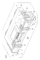
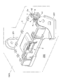
- FIG. 1 is a diagram illustrating an example of a configuration of a vehicle electronic control device 100 according to the embodiment.
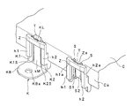
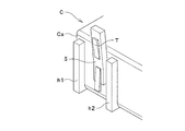
- FIG. 2 is an enlarged view of a region where the resin case C and the attachment member K of the vehicle electronic control device 100 shown in FIG. 1 are fixed.
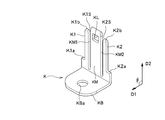
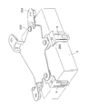
- FIG. 3 is a diagram showing an example of the configuration of the attachment member K of the vehicle electronic control device 100 shown in FIG.
- FIG. 4 is a view of the region where the resin case C and the attachment member K of the vehicle electronic control device 100 shown in FIG. 1 are fixed as seen from above.
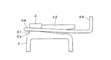
- FIG. 5 is a diagram showing an example of a cross section including the central plate portion KM along the line BB in the region shown in FIG. FIG.
- FIG. 6 is a diagram showing an example of a cross section including the second end plate portion K2 along the line AA in the region shown in FIG.
- FIG. 7 is a diagram illustrating an example of the configuration of the vehicle electronic control device 200 according to the second embodiment.
- FIG. 8 is an exploded view of the vehicle electronic control device 200 shown in FIG. 7 before assembly.
- FIG. 9 is a diagram illustrating an example of a configuration of a side region to which the attachment member K of the vehicle electronic control device 200 shown in FIG. 7 is attached.
- FIG. 10 is a diagram showing an example of the configuration of the attachment member K of the vehicle electronic control device 200 shown in FIG.
- FIG. 11 is a diagram illustrating an example of the configuration of the vehicle electronic control device 300 according to the third embodiment.
- FIG. 1 is a diagram illustrating an example of a configuration of a vehicle electronic control device 100 according to an embodiment.
- FIG. 2 is an enlarged view of a region where the resin case C and the attachment member K of the vehicle electronic control device 100 shown in FIG. 1 are fixed.
- FIG. 3 is a diagram showing an example of the configuration of the attachment member K of the vehicle electronic control device 100 shown in FIG.
- FIG. 4 is a view of the region where the resin case C and the attachment member K of the vehicle electronic control device 100 shown in FIG. 1 are fixed as seen from above.
- FIG. 5 is a diagram showing an example of a cross section including the central plate portion KM along the line BB in the region shown in FIG.
- FIG. 6 is a diagram showing an example of a cross section including the second end plate portion K2 along the line AA in the region shown in FIG.
- FIG. 1 for simplicity, a part of the vehicle that is the fixing target member 1000 is illustrated, but screws and the like that fix the fixing target member 1000 and the vehicle electronic control device 100 are omitted. Yes.
- the vehicle electronic control device 100 includes a control unit X, a substrate Y, a resin case C, an attachment member (metal fitting) K, a terminal unit G, and a case cover F.
- the control unit X performs predetermined electronic control.
- This control part X is ECU which performs control of the behavior of a vehicle, such as a motor vehicle and a two-wheeled vehicle, and an engine, for example.
- the fixation target member 1000 is loaded on the vehicle, and the control unit X is an ECU for controlling the behavior of the vehicle.
- the substrate Y is mounted with a control unit X, other electronic components, wiring, a terminal unit G, and the like.
- the terminal part G is electrically connected to the control part X and other electronic components by the wiring or the like, and can input / output a predetermined signal for controlling the behavior of the vehicle. .
- the resin case C houses a substrate Y on which the control unit X is placed.
- the case cover F is configured such that the engagement portions F ⁇ b> 1 and F ⁇ b> 2 are locked to the resin case C so as to cover the opening Cb of the resin case C. Fixed to. By fixing the case cover F to the resin case C, the substrate Y on which the control unit X is loaded is sealed inside the resin case C.
- the resin case C includes, for example, as shown in FIGS. 1 to 4, a protruding portion T, a first holding portion h1 and a second holding portion h2, slope portions S1 and S2, and a supporting portion. Z.
- the first restraining portion h1 and the second restraining portion h2 are provided on the side surface Ca of the resin case C so as to restrain the mounting member K and guide it to the predetermined position.
- the first holding part h1 is configured to guide the first end plate part K1 to the predetermined position while holding the first end plate part K1 between the side face Ca of the resin case C.
- the first end plate portion K1 is guided in the groove formed by the first holding portion h1 and the side surface Ca of the resin case C.
- the first holding portion h1 is provided to face the side surface Ca of the resin case C so as to extend in parallel to the direction in which the mounting member K is guided.
- suppressing part h2 guides the 2nd end plate part K2 to this predetermined position, suppressing the 2nd end plate part K2 between the side surfaces Ca of the resin case C. .
- the second end plate portion K2 is guided in the groove formed by the second holding portion h2 and the side surface Ca of the resin case C.
- the second holding portion h2 is provided to face the side surface Ca of the resin case C so as to extend in parallel to the direction in which the mounting member K is guided.
- the first and second end plate portions K1, K2 are used in a state where the attachment member K is guided to the predetermined position (fixed to the resin case C).
- the first and second end plate portions K1, K2 are used.
- the angle between the direction in which the base KB extends and the direction in which the first and second end plate portions K1 and K2 extend is changed from a right angle to an obtuse angle.
- slope portions S1 and S2 are provided on the side surface Ca of the resin case C.
- two slope portions S ⁇ b> 1 and S ⁇ b> 2 are provided for one attachment member K, but one or three or more slope portions may be provided.
- the slope portions S1 and S2 are arranged such that the first and second end plate portions K1 and K2 are guided by the first and second holding portions h1 and h2, so that the central plate portion KM comes into contact with the central plate portion KM.
- the KM is elastically deformed.
- the central plate portion KM comes into contact with the slope portions S1 and S2 and slides (guides) toward the predetermined position, the central plate portion KM is elastically deformed so that the central plate portion KM suppresses the protruding portion T by elastic force. It has become.
- the support portion Z is connected between the surface of the first restraining portion h1 and the surface of the second restraining portion h2 (the portion that does not face the side surface Ca of the resin case C) and is connected to the side surface Ca of the resin case C. It is provided so as to face at least partially.
- the protruding portion T is provided on the side surface Za (side surface facing the resin case C) of the support portion Z so as to face the side surface Ca of the resin case C.
- the attachment member K has an elastic force for attaching the resin case C directly or indirectly to the fixation target member 1000.
- the mounting member K is made of a conductive member such as metal.
- the substrate Y may be electrically connected to an external ground via the attachment member K.
- attachment member K is formed by integral molding, for example.
- the attachment member K includes a base KB, a center plate KM, a first end plate K1, a second end plate K2, 1 stopper part K1a and 2nd stopper part K2a.
- the base KB extends in the first direction D1, and is fixed directly or indirectly to the fixing target member 1000. Further, a screw hole KBa for screwing the attachment member K to the fixing target member 1000 is formed in the base KB.
- the central plate portion KM includes an engaging portion KL that extends from the base KB and engages the protruding portion T at a predetermined position.
- the engaging portion KL of the central plate portion KM is an opening penetrating the tip portion of the central plate portion KM, for example, as shown in FIGS.
- the protrusion T is inserted into the opening, which is the engagement portion KL, and the tip portion of the central plate portion KM restrains the protrusion T by elastic force, so that the protrusion T is engaged with the engagement portion KL. It is like that.
- the position where the engaging portion KL of the central plate portion KM is engaged with the protruding portion T corresponds to the predetermined position described above, and this predetermined position is the resin case. This is the position where the attachment member K is fixed to C.
- first end plate portion K1 extends from the base KB so as to be adjacent to the first side portion of the central plate portion KM through the first slit K1S.
- the tip end portion K1b of the first end plate portion K1 is arranged in a direction in which the first slit K1S extends in order to guide the first end plate portion K1 to the predetermined position with respect to the first holding portion h1. In contrast, it is inclined (FIG. 3).
- the second end plate portion K2 extends from the base KB so as to be adjacent to the second side portion of the central plate portion KM through the second slit K2S.
- tip end portion K1b of the second end plate portion K2 is arranged in a direction in which the second slit K2S extends in order to guide the second end plate portion K2 to the predetermined position with respect to the second holding portion h2. In contrast, it is inclined (FIG. 3).
- a first stopper K1a is formed on the base KB side of the first end plate K1
- a first stopper K1a is formed on the base KB side of the second end plate K2.
- Two stopper portions K2a are formed.
- the first stopper portion K1a and the second stopper portion K2a allow the engaging portion KL of the central plate portion KM to engage with the protruding portion T at the predetermined position, for example, as shown in FIG. It is for (edge).
- first stopper portion K1a abuts on the end portion of the first restraining portion h1
- the second stopper portion abuts on the end portion of the second restraining portion h2 so that the central plate portion KM
- the engaging portion KL engages the protruding portion T at the predetermined position (FIGS. 1 and 2).
- the central plate portion KM and the first and second end plate portions K1, K2 extend in the first direction. Extends from the base KB to the second direction D2 (FIG. 3).
- the first direction D1 of the base KB and the first and second end plate portions K1, K2 are used in the mounting member K before the mounting member K is fixed to the resin case C.
- the angle ⁇ between the second direction D2 and the second direction D2 is a right angle.
- the first direction D1 of the base KB and the first and second directions so that the elastic force after fixation increases.
- the angle between the end plate portions K1 and K2 and the second direction D2 may be an acute angle or an obtuse angle.
- the first end plate portion K1 is guided by the first restraining portion h1
- the second end plate portion K2 is guided by the second restraining portion h2
- the engaging portion KL of the central plate portion KM is in a predetermined position.
- the mounting member K is fixed to the resin case C by engaging the protruding portion T and the central plate portion KM suppressing the protruding portion T by elastic force.
- the direction in which the base KB extends and the central plate portion KM is an acute angle.
- the direction in which the base KB extends and the first and second ends is an obtuse angle.
- the vehicle electronic control device 100 is configured to fix the attachment member K to the resin case C while elastically deforming the central plate portion KM of the attachment member K by the slope portions S1 and S2.
- the attachment member K is fixed to the resin case C by being guided to the position and engaging the opening of the attachment member K and the protrusion T of the resin case C.
- a substrate Y on which a control unit X is placed is stored in a resin case C.
- the case cover F covers the opening Cb of the resin case C by engaging the engaging portions F ⁇ b> 1 and F ⁇ b> 2 with the resin case C. Secure to.
- the attachment member K is fixed to the resin case C. More specifically, as described above, the first end plate portion K1 is guided by the first restraining portion h1, and the second end plate portion K2 is guided by the second restraining portion h2, and the central plate portion KM. Advances while being elastically deformed by the slopes of the slope portions S1, S2. Then, the engaging member KL of the central plate portion KM engages the protruding portion T at a predetermined position, and the central plate portion KM suppresses the protruding portion T by an elastic force, whereby the attachment member K is fixed to the resin case C.
- the attachment member K When the engaging portion KL (opening portion) of the central plate portion KM is engaged with the protruding portion T, the attachment member K is fixed to the resin case C without a gap by the restoring force of the central plate portion KM. Even in the fixed state, the attachment member K is elastically deformed because it is pressed by the slope portions S1 and S2.
- the direction in which the base KB extends and the central plate portion KM is an acute angle.
- the direction in which the base KB extends and the first and second ends is an obtuse angle.
- the vehicle electronic control device 100 is fixed to the fixing target member 1000, that is, the vehicle.
- the vehicle electronic control device includes a control unit that performs predetermined electronic control, a substrate on which the control unit is mounted, and a substrate on which the control unit is mounted. And a mounting member having an elastic force for mounting the resin case directly or indirectly to the member to be fixed.
- the resin case has a protrusion, and a first holding part and a second holding part for holding and guiding the mounting member.
- the mounting member extends in the first direction and is directly or indirectly fixed to the member to be fixed, and extends from the base in a direction different from the first direction, and the protrusion is positioned at a predetermined position.
- a central plate part including an engaging part engaged with the first end plate part extending from the base so as to be adjacent to the first side part of the central plate part via the first slit; And a second end plate portion extending from the base portion so as to be adjacent to the second side portion of the central plate portion via the two slits.
- the first end plate portion is guided by the first holding portion and the second end plate portion is guided by the second holding portion, and the engaging portion of the central plate portion engages the protruding portion at a predetermined position.
- the mounting member is fixed to the resin case by the central plate portion restraining the protruding portion by elastic force.
- the attachment member remains elastically deformed even when fixed to the vehicle, so that the attachment member is sufficiently fixed to the resin case without a gap and the vehicle body vibrates. Even so, the swing of the resin case storing the substrate with respect to the vehicle body can be suppressed.
- the mounting member is elastically deformed, even if there is a manufacturing variation in the size of the gap between the mounting member and the resin case, it is possible to reduce the influence on the fixing of the mounting member to the resin case.
- the support member Z may be omitted, and the protruding portion T may be provided on the slope portion S of the side surface Ca of the resin case C.
- FIG. 7 is a diagram illustrating an example of the configuration of the vehicle electronic control device 200 according to the second embodiment.
- FIG. 8 is a developed view of the vehicle electronic control device 200 shown in FIG. 7 before assembly.
- FIG. 9 is a diagram showing an example of a configuration of a side region to which the attachment member K of the vehicle electronic control device 200 shown in FIG. 7 is attached.
- FIG. 10 is a diagram showing an example of the configuration of the attachment member K of the vehicle electronic control device 200 shown in FIG. 7 to 10, the same reference numerals as those in the first embodiment indicate the same configuration, and the description thereof is omitted.
- the vehicle electronic control device 200 includes a control unit X, a substrate Y, a resin case C, an attachment member (metal fitting) K, and a terminal unit G.
- the vehicle body side member 201 is connected to a fixed member 1000 loaded on the vehicle.
- fixing member (screw) 202 fixes the attachment member K and the vehicle body side member.
- the resin case C includes a protruding portion T, a first holding portion h1 and a second holding portion h2, a slope portion S, and a support portion Z.
- the protruding portion T is provided at the tip of the slope portion S provided on the side surface Ca of the resin case C.
- the attachment member K includes a base KB, a center plate KM, a first end plate K1, a second end plate K2, a first stopper K1a, A second stopper portion K2a.
- the vehicle electronic control device 200 is different in that the protrusion T is provided on the slope portion S of the side surface Ca of the resin case C with respect to the basic configuration.
- the first end plate portion K1 is guided by the first restraining portion h1 and the second end plate portion K2 is guided by the second restraining portion h2, and the central plate portion
- the attachment member K is fixed to the resin case C when the engaging portion KL of the KM engages the protruding portion T at a predetermined position and the central plate portion KM suppresses the protruding portion T by elastic force. .
- the attachment member remains elastically deformed even when fixed to the vehicle, so that the attachment member is sufficiently fixed to the resin case without a gap and the vehicle body vibrates. Even so, the swing of the resin case storing the substrate with respect to the vehicle body can be suppressed.
- the mounting member is elastically deformed as in the first embodiment, there is a manufacturing variation in the size of the gap between the mounting member and the resin case. Even so, it is possible to reduce the influence on the fixing of the mounting member to the resin case.
- FIG. 11 is a diagram illustrating an example of the configuration of the vehicle electronic control device 300 according to the third embodiment.
- the same reference numerals as those in the first and second embodiments indicate the same configuration, and thus the description thereof is omitted.
- a boss may be provided on the lower surface of the resin case C, and an opening may be provided in the base KB of the attachment member K so that they can be fitted together. Thereby, the fluctuation
- the first end plate portion K1 is guided by the first restraining portion h1 and the second end, as in the first and second embodiments.
- the plate portion K2 is guided by the second restraining portion h2, the engaging portion KL of the central plate portion KM engages the projecting portion T at a predetermined position, and the central plate portion KM restrains the projecting portion T by elastic force.
- the attachment member K is fixed to the resin case C.
- the attachment member remains elastically deformed even when fixed to the vehicle, so that the attachment member is sufficiently fixed to the resin case without a gap and the vehicle body vibrates. Even so, the swing of the resin case storing the substrate with respect to the vehicle body can be suppressed.
- the mounting member is elastically deformed as in the first embodiment, there is a manufacturing variation in the size of the gap between the mounting member and the resin case. Even so, it is possible to reduce the influence on the fixing of the mounting member to the resin case.
- the attachment member remains elastically deformed even when fixed to the vehicle, so that the attachment member is sufficiently fixed to the resin case without a gap and the vehicle body vibrates. Even so, the swing of the resin case storing the substrate with respect to the vehicle body can be suppressed.
- the mounting member is elastically deformed, even if there is a manufacturing variation in the size of the gap between the mounting member and the resin case, it is possible to reduce the influence on the fixing of the mounting member to the resin case.
Landscapes
- Engineering & Computer Science (AREA)
- Mechanical Engineering (AREA)
- Microelectronics & Electronic Packaging (AREA)
- Casings For Electric Apparatus (AREA)
Abstract
車両用電子制御装置は、所定の電子制御を実行する制御部と、制御部が載置された基板と、制御部が載置された前記基板を内部に収納する樹脂ケースと、樹脂ケースを固定対象部材に直接的又は間接的に取り付けるための弾性力を有する取り付け部材と、を備え、樹脂ケースは、突起部と、取り付け部材を抑え且つ案内するための第1の抑え部及び第2の抑え部と、を有する。
Description
本発明は、車両用電子制御装置に関する発明である。
従来、車両用電子制御装置の車体への取り付けでは、電子部品が実装された基板を金属ケースに収納し、当該金属ケースと車体側部材とをネジで固定している。
近年、軽量化のため、樹脂ケースを適用することが求められている。一方、樹脂ケースと車体側部材との間の取り付け部品は金属製でなければならない。
このため、樹脂ケースと取り付け部材(ブラケット)との結合部分の構造に工夫が必要となっている。
そして、樹脂ケースを用いた例では、樹脂ケースの側面に、取り付け部材を挿入するための溝部を設け、この溝部に突起部を設けている。
当該突起部が取り付け部材の開口部と係合することで、取り付け部材が樹脂ケースに固定される。特に、樹脂ケースの溝部に下側から挿入された取り付け部材は、樹脂ケースが(変形して、開口部と突起部が係合することで樹脂ケースに固定される。
しかしながら、変形した樹脂ケースは劣化により弾性力を失うため、取り付け部材と樹脂ケースの間には隙間が生じる。
すなわち、上記従来の車両用電子制御装置では、取り付け部材と樹脂ケースとの間が十分に固定されず、車体の振動に伴って、基板を収納した樹脂ケースが当該車体に対して揺動して、当該基板に積載された電子部品等の故障の原因になり得る。
上述のように、従来の車両用電子制御装置では、取り付け部材と樹脂ケースとの間が十分に固定されず、車体の振動に伴って、基板を収納した樹脂ケースが当該車体に対して揺動する問題がある。
そこで、本発明では、取り付け部材と樹脂ケースとの間を十分に固定して、基板を収納した樹脂ケースの車体に対する揺動を抑制することが可能な車両用電子制御装置を提供することを目的とする。
本発明の一態様に係る実施形態に従った車両用電子制御装置は、
所定の電子制御を実行する制御部と、
前記制御部が載置された基板と、
前記制御部が載置された前記基板を内部に収納する樹脂ケースと、
前記樹脂ケースを固定対象部材に直接的又は間接的に取り付けるための弾性力を有する取り付け部材と、を備え、
前記樹脂ケースは、突起部と、前記取り付け部材を抑え且つ案内するための第1の抑え部及び第2の抑え部と、を有し、
前記取り付け部材は、
第1の方向に延在し、前記固定対象部材に直接的又は間接的に固定される基部と、
前記基部から前記第1の方向と異なる方向に延在し、前記突起部を所定位置で係合する係合部を含む中央プレート部と、
第1のスリットを介して前記中央プレート部の第1の側部に隣接するように、前記基部から延在する第1の端プレート部と、
第2のスリットを介して前記中央プレート部の第2の側部に隣接するように、前記基部から延在する第2の端プレート部と、を有し、
前記第1の端プレート部が前記第1の抑え部で案内され且つ前記第2の端プレート部が前記第2の抑え部で案内され、前記中央プレート部の前記係合部が前記所定位置で前記突起部を係合し且つ前記中央プレート部が弾性力により前記突起部を抑えることにより、前記取り付け部材が前記樹脂ケースに固定される
ことを特徴とする。
所定の電子制御を実行する制御部と、
前記制御部が載置された基板と、
前記制御部が載置された前記基板を内部に収納する樹脂ケースと、
前記樹脂ケースを固定対象部材に直接的又は間接的に取り付けるための弾性力を有する取り付け部材と、を備え、
前記樹脂ケースは、突起部と、前記取り付け部材を抑え且つ案内するための第1の抑え部及び第2の抑え部と、を有し、
前記取り付け部材は、
第1の方向に延在し、前記固定対象部材に直接的又は間接的に固定される基部と、
前記基部から前記第1の方向と異なる方向に延在し、前記突起部を所定位置で係合する係合部を含む中央プレート部と、
第1のスリットを介して前記中央プレート部の第1の側部に隣接するように、前記基部から延在する第1の端プレート部と、
第2のスリットを介して前記中央プレート部の第2の側部に隣接するように、前記基部から延在する第2の端プレート部と、を有し、
前記第1の端プレート部が前記第1の抑え部で案内され且つ前記第2の端プレート部が前記第2の抑え部で案内され、前記中央プレート部の前記係合部が前記所定位置で前記突起部を係合し且つ前記中央プレート部が弾性力により前記突起部を抑えることにより、前記取り付け部材が前記樹脂ケースに固定される
ことを特徴とする。
前記車両用電子制御装置において、
前記樹脂ケースは、
前記第1及び第2の端プレート部が前記第1及び第2の抑え部で案内されることで、前記中央プレート部と接触して前記中央プレート部を弾性変形させるスロープ部をさらに備え、
前記中央プレート部が弾性変形することにより、中央プレート部が弾性力により前記突起部を抑える
ことを特徴とする。
前記樹脂ケースは、
前記第1及び第2の端プレート部が前記第1及び第2の抑え部で案内されることで、前記中央プレート部と接触して前記中央プレート部を弾性変形させるスロープ部をさらに備え、
前記中央プレート部が弾性変形することにより、中央プレート部が弾性力により前記突起部を抑える
ことを特徴とする。
前記車両用電子制御装置において、
前記第1の抑え部と前記第2の抑え部とは、前記取り付け部材を案内する方向に平行に延在するように、前記樹脂ケースの側面に対向して設けられている
ことを特徴とする。
前記第1の抑え部と前記第2の抑え部とは、前記取り付け部材を案内する方向に平行に延在するように、前記樹脂ケースの側面に対向して設けられている
ことを特徴とする。
前記車両用電子制御装置において、
前記突起部は、前記スロープ部の先端に設けられている
ことを特徴とする。
前記突起部は、前記スロープ部の先端に設けられている
ことを特徴とする。
前記車両用電子制御装置において、
前記樹脂ケースは、前記第1の抑え部の表面と前記第2の抑え部の表面との間に接続され且つ前記樹脂ケースの前記側面に対向するように設けられた支持部をさらに備え、
前記突起部は、前記樹脂ケースの前記側面に対向するように、前記支持部の側面に設けられている
ことを特徴とする。
前記樹脂ケースは、前記第1の抑え部の表面と前記第2の抑え部の表面との間に接続され且つ前記樹脂ケースの前記側面に対向するように設けられた支持部をさらに備え、
前記突起部は、前記樹脂ケースの前記側面に対向するように、前記支持部の側面に設けられている
ことを特徴とする。
前記車両用電子制御装置において、
前記係合部は、前記中央プレート部の先端部分を貫通する開口部であり、
前記開口部に前記突起部が挿入されるとともに前記中央プレート部の前記先端部分が弾性力により前記突起部を抑えることで、前記突起部が前記係合部に係合される
ことを特徴とする。
前記係合部は、前記中央プレート部の先端部分を貫通する開口部であり、
前記開口部に前記突起部が挿入されるとともに前記中央プレート部の前記先端部分が弾性力により前記突起部を抑えることで、前記突起部が前記係合部に係合される
ことを特徴とする。
前記車両用電子制御装置において、
前記取り付け部材は、前記中央プレート部の前記係合部が前記所定位置で前記突起部を係合できようにするための、前記第1の端プレート部に形成された第1のストッパー部、及び、前記第2の端プレート部に形成された第2のストッパー部を有し、
前記第1のストッパー部が前記第1の抑え部の端部に当接し、且つ、第2のストッパー部が前記第2の抑え部の端部に当接することで、前記中央プレート部の前記係合部が前記所定位置で前記突起部を係合する
ことを特徴とする。
前記取り付け部材は、前記中央プレート部の前記係合部が前記所定位置で前記突起部を係合できようにするための、前記第1の端プレート部に形成された第1のストッパー部、及び、前記第2の端プレート部に形成された第2のストッパー部を有し、
前記第1のストッパー部が前記第1の抑え部の端部に当接し、且つ、第2のストッパー部が前記第2の抑え部の端部に当接することで、前記中央プレート部の前記係合部が前記所定位置で前記突起部を係合する
ことを特徴とする。
前記車両用電子制御装置において、
前記第1の端プレート部の先端部分は、前記第1の抑え部に対して前記第1の端プレート部を所定位置に案内するために、前記第1のスリットが延びる方向に対して傾斜しているとともに、
前記第2の端プレート部の先端部分は、前記第2の抑え部に対して前記第2の端プレート部を所定位置に案内するために、前記第2のスリットが延びる方向に対して傾斜している
ことを特徴とする。
前記第1の端プレート部の先端部分は、前記第1の抑え部に対して前記第1の端プレート部を所定位置に案内するために、前記第1のスリットが延びる方向に対して傾斜しているとともに、
前記第2の端プレート部の先端部分は、前記第2の抑え部に対して前記第2の端プレート部を所定位置に案内するために、前記第2のスリットが延びる方向に対して傾斜している
ことを特徴とする。
前記車両用電子制御装置において、
前記取り付け部材において、前記取り付け部材が前記樹脂ケースに固定された状態では、前記基部が延在する方向と、前記第1及び第2の端プレート部が延在する方向と、の間の角度は、鈍角である
ことを特徴とする。
前記取り付け部材において、前記取り付け部材が前記樹脂ケースに固定された状態では、前記基部が延在する方向と、前記第1及び第2の端プレート部が延在する方向と、の間の角度は、鈍角である
ことを特徴とする。
前記車両用電子制御装置において、
前記取り付け部材において、前記取り付け部材が前記樹脂ケースに固定された状態では、前記基部が延在する方向と、前記中央プレート部が延在する方向と、の間の角度は、鋭角である
ことを特徴とする。
前記取り付け部材において、前記取り付け部材が前記樹脂ケースに固定された状態では、前記基部が延在する方向と、前記中央プレート部が延在する方向と、の間の角度は、鋭角である
ことを特徴とする。
前記車両用電子制御装置において、
前記取り付け部材において、前記取り付け部材が前記樹脂ケースに固定される前の状態では、前記中央プレート部及び第1、第2の端プレート部は、前記基部から前記第1の方向と異なる第2の方向に延在している
ことを特徴とする。
前記取り付け部材において、前記取り付け部材が前記樹脂ケースに固定される前の状態では、前記中央プレート部及び第1、第2の端プレート部は、前記基部から前記第1の方向と異なる第2の方向に延在している
ことを特徴とする。
前記車両用電子制御装置において、
前記取り付け部材において、前記取り付け部材が前記樹脂ケースに固定される前の状態では、前記基部の前記第1の方向と、前記第1及び第2の端プレート部の前記第2の方向と、の間の角度は、鋭角、又は、鈍角であることを特徴とする。
前記取り付け部材において、前記取り付け部材が前記樹脂ケースに固定される前の状態では、前記基部の前記第1の方向と、前記第1及び第2の端プレート部の前記第2の方向と、の間の角度は、鋭角、又は、鈍角であることを特徴とする。
前記車両用電子制御装置において、
前記固定対象部材は、車両に積載されており、前記制御部は、前記車両の挙動を制御するためのECUである
ことを特徴とする。
前記固定対象部材は、車両に積載されており、前記制御部は、前記車両の挙動を制御するためのECUである
ことを特徴とする。
前記車両用電子制御装置において、
前記車両に積載された前記固定対象部材に接続される車体側部材と、
前記取り付け部材と前記車体側部材とを固定する固定部材と、をさらに備える
ことを特徴とする。
前記車両に積載された前記固定対象部材に接続される車体側部材と、
前記取り付け部材と前記車体側部材とを固定する固定部材と、をさらに備える
ことを特徴とする。
前記車両用電子制御装置において、
前記取り付け部材は、金属で構成され、前記基板は、取り付け部材を介して外部のグランドに電気的に接続されている
ことを特徴とする。
前記取り付け部材は、金属で構成され、前記基板は、取り付け部材を介して外部のグランドに電気的に接続されている
ことを特徴とする。
本発明の一態様に係る車両用電子制御装置は、所定の電子制御を実行する制御部と、制御部が載置された基板と、制御部が載置された基板を内部に収納する樹脂ケースと、樹脂ケースを固定対象部材に直接的又は間接的に取り付けるための弾性力を有する取り付け部材と、を備える。
そして、樹脂ケースは、突起部と、取り付け部材を抑え且つ案内するための第1の抑え部及び第2の抑え部と、を有する。
そして、取り付け部材は、第1の方向に延在し、固定対象部材に直接的又は間接的に固定される基部と、基部から第1の方向と異なる方向に延在し、突起部を所定位置で係合する係合部を含む中央プレート部と、第1のスリットを介して中央プレート部の第1の側部に隣接するように、基部から延在する第1の端プレート部と、第2のスリットを介して中央プレート部の第2の側部に隣接するように、基部から延在する第2の端プレート部と、を有する。
そして、第1の端プレート部が第1の抑え部で案内され且つ第2の端プレート部が第2の抑え部で案内され、中央プレート部の係合部が所定位置で突起部を係合し且つ中央プレート部が弾性力により突起部を抑えることにより、取り付け部材が樹脂ケースに固定される。
すなわち、本発明の車両用電子制御装置では、車両に固定された状態においても、取り付け部材は弾性変形したままなので、取り付け部材は隙間無く樹脂ケースに十分に固定され、車体が振動した場合であっても、基板を収納した樹脂ケースの車体に対する揺動を抑制することができる。
さらに、取り付け部材を弾性変形させるため、取り付け部材と樹脂ケースの間の隙間の大きさに製造上のバラツキがあったとしても、取り付け部材の樹脂ケースへの固定に対する影響を低減することができる。
以下、本発明に係る実施形態について図面に基づいて説明する。
図1は、実施形態に係る車両用電子制御装置100の構成の一例を示す図である。また、図2は、図1に示す車両用電子制御装置100の樹脂ケースCと取り付け部材Kとが固定されている領域を拡大した図である。また、図3は、図1に示す車両用電子制御装置100の取り付け部材Kの構成の一例を示す図である。また、図4は、図1に示す車両用電子制御装置100の樹脂ケースCと取り付け部材Kとが固定されている領域を上方から見た図である。また、図5は、図4に示す領域のB-B線に沿った中央プレート部KMを含む断面の一例を示す図である。また、図6は、図4に示す領域のA-A線に沿った第2の端プレート部K2を含む断面の一例を示す図である。
なお、図1においては、簡単のため、固定対象部材1000である車両の一部を図示しているが、この固定対象部材1000と車両用電子制御装置100とを固定するネジ等は省略されている。
図1に示すように、車両用電子制御装置100は、制御部Xと、基板Yと、樹脂ケースCと、取り付け部材(金具)Kと、端子部Gと、ケースカバーFと、を備える。
制御部Xは、所定の電子制御を実行するようになっている。この制御部Xは、例えば、自動車、二輪車等の車両の挙動やエンジンの制御を実行するECUである。ここでは、固定対象部材1000は、当該車両に積載されており、制御部Xは、当該車両の挙動を制御するためのECUである。
また、基板Yは、制御部X、その他の電子部品、配線、端子部G等が載置されている。なお、端子部Gは、制御部X、その他の電子部品と、上記配線等により電気的に接続さて、当該車両の挙動の制御を実行するための所定の信号の入出力が可能になっている。
また、樹脂ケースCは、例えば、図1に示すように、制御部Xが載置された基板Yを内部に収納している。
また、ケースカバーFは、例えば、図1に示すように、係合部F1、F2が樹脂ケースCに係止されることで、樹脂ケースCの開口部Cbをカバーする状態で、樹脂ケースCに固定される。このケースカバーFが樹脂ケースCに固定されることで、制御部Xを積載した基板Yが、樹脂ケースCの内部に封止される。
ここで、上記樹脂ケースCは、例えば、図1から図4に示すように、突起部Tと、第1の抑え部h1及び第2の抑え部h2と、スロープ部S1、S2と、支持部Zと、を有する。
第1の抑え部h1及び第2の抑え部h2は、樹脂ケースCの側面Caに設けられ、取り付け部材Kを抑え且つ該所定位置まで案内するようになっている。
第1の抑え部h1は、樹脂ケースCの側面Caとの間で第1の端プレート部K1を抑えつつ、第1の端プレート部K1を該所定位置まで案内するようになっている。なお、図1、図2、図4の例では、第1の抑え部h1と樹脂ケースCの側面Caで構成される溝に第1の端プレート部K1が案内されるようになっている。
この第1の抑え部h1は、取り付け部材Kを案内する方向に平行に延在するように、樹脂ケースCの側面Caに対向して設けられている。
そして、第2の抑え部h2は、樹脂ケースCの側面Caとの間で第2の端プレート部K2を抑えつつ、第2の端プレート部K2を該所定位置まで案内するようになっている。なお、図1、図2、図4の例では、第2の抑え部h2と樹脂ケースCの側面Caで構成される溝に第2の端プレート部K2が案内されるようになっている。
この第2の抑え部h2とは、取り付け部材Kを案内する方向に平行に延在するように、樹脂ケースCの側面Caに対向して設けられている。
なお、例えば、図4、図6に示すように、取り付け部材Kが該所定位置に案内された状態(樹脂ケースCに固定された状態)では、第1、第2の端プレート部K1、K2がそれぞれ第1、第2の抑え部h1、H2と接触していることで変形している。これにより、基部KBが延在する方向と、第1及び第2の端プレート部K1、K2が延在する方向と、の間の角度は、直角から鈍角になる。
また、スロープ部S1、S2は、樹脂ケースCの側面Caに設けられている。なお、図1、図2の例では、1個の取り付け部材Kに対して2つのスロープ部S1、S2が設けられているが、当該スロープ部は1個又は3個以上であってもよい。
このスロープ部S1、S2は、第1及び第2の端プレート部K1、K2が第1及び第2の抑え部h1、h2で案内されることで、中央プレート部KMと接触して中央プレート部KMを弾性変形させるようになっている。
中央プレート部KMがスロープ部S1、S2と接触して当該所定位置に向けてスライドする(案内される)ことで弾性変形することにより、中央プレート部KMが弾性力により突起部Tを抑えるようになっている。
例えば、図4、図5に示すように、取り付け部材Kが該所定位置に案内された状態(樹脂ケースCに固定された状態)では、中央プレート部KMがスロープ部S1、S2と接触していることで変形している。これにより、基部KBが延在する方向と、中央プレート部KMが延在する方向と、の間の角度は、直角から鋭角になる。
また、支持部Zは、第1の抑え部h1の表面と第2の抑え部h2の表面(樹脂ケースCの側面Caと対向しない部分)との間に接続され且つ樹脂ケースCの側面Caに少なくとも部分的に対向するように設けられている。
また、突起部Tは、樹脂ケースCの側面Caに対向するように、支持部Zの側面Za(樹脂ケースCに対向する側面)に設けられている。
また、取り付け部材Kは、樹脂ケースCを固定対象部材1000に直接的又は間接的に取り付けるための弾性力を有する。
この取り付け部材Kは、導電性を有する部材、例えば、金属で構成される。この場合、基板Yは、取り付け部材Kを介して外部のグランドに電気的に接続されるようにしてもよい。
また、取り付け部材Kは、例えば、一体成形により形成されている。
ここで、この取り付け部材Kは、例えば、図1から図3に示すように、基部KBと、中央プレート部KMと、第1の端プレート部K1と、第2の端プレート部K2と、第1のストッパー部K1aと、第2のストッパー部K2aと、を有する。
基部KBは、第1の方向D1に延在し、固定対象部材1000に直接的又は間接的に固定されるようになっている。また、この基部KBには、固定対象部材1000に取り付け部材Kをネジ止めするためのネジ穴KBaが形成されている。
中央プレート部KMは、基部KBから延在し、突起部Tを所定位置で係合する係合部KLを含む。
この中央プレート部KMの係合部KLは、例えば、図1ないし図3に示すように、中央プレート部KMの先端部分を貫通する開口部である。
この係合部KLである開口部に突起部Tが挿入されるとともに中央プレート部KMの先端部分が弾性力により突起部Tを抑えることで、突起部Tが係合部KLに係合されるようになっている。
そして、この中央プレート部KMの係合部KLが突起部Tに係合した(突起部Tが開口部に挿入された)位置が、既述の所定位置に対応し、この所定位置が樹脂ケースCに取り付け部材Kが固定されている位置である。
また、第1の端プレート部K1は、第1のスリットK1Sを介して中央プレート部KMの第1の側部に隣接するように、基部KBから延在している。
また、第1の端プレート部K1の先端部分K1bは、第1の抑え部h1に対して第1の端プレート部K1を該所定位置に案内するために、第1のスリットK1Sが延びる方向に対して傾斜している(図3)。
また、第2の端プレート部K2は、第2のスリットK2Sを介して中央プレート部KMの第2の側部に隣接するように、基部KBから延在している。
また、第2の端プレート部K2の先端部分K1bは、第2の抑え部h2に対して第2の端プレート部K2を該所定位置に案内するために、第2のスリットK2Sが延びる方向に対して傾斜している(図3)。
また、例えば、図3に示すように、第1の端プレート部K1の基部KB側には第1のストッパー部K1aが形成され、及び、第2の端プレート部K2の基部KB側には第2のストッパー部K2aが形成されている。これらの第1のストッパー部K1a及び第2のストッパー部K2aは、例えば、図3に示すように、中央プレート部KMの係合部KLが該所定位置で突起部Tと係合できようにするためのもの(エッジ)である。
すなわち、第1のストッパー部K1aが第1の抑え部h1の端部に当接し、且つ、第2のストッパー部が第2の抑え部h2の端部に当接することで、中央プレート部KMの係合部KLが当該所定位置で突起部Tを係合するようになっている(図1、図2)。
ここで、取り付け部材Kにおいて、取り付け部材Kが樹脂ケースCに固定される前の状態では、中央プレート部KM及び第1、第2の端プレート部K1、K2は、第1の方向に延在する基部KBから、第2の方向D2に延在している(図3)。
この図3の例では、取り付け部材Kにおいて、取り付け部材Kが樹脂ケースCに固定される前の状態では、基部KBの第1の方向D1と、第1及び第2の端プレート部K1、K2の第2の方向D2と、の間の角度θは、直角である。
なお、取り付け部材Kにおいて、取り付け部材Kが樹脂ケースCに固定される前の状態では、固定後の弾性力が増加するように、基部KBの第1の方向D1と、第1及び第2の端プレート部K1、K2の第2の方向D2と、の間の角度は、鋭角、又は、鈍角であるようにしてもよい。
そして、第1の端プレート部K1が第1の抑え部h1で案内され且つ第2の端プレート部K2が第2の抑え部h2で案内され、中央プレート部KMの係合部KLが所定位置で突起部Tを係合し且つ中央プレート部KMが弾性力により突起部Tを抑えることにより、取り付け部材Kが樹脂ケースCに固定されるようになっている。
そして、例えば、既述の図4、図5に示すように、取り付け部材Kにおいて、取り付け部材Kが樹脂ケースCに固定された状態では、基部KBが延在する方向と、中央プレート部KMが延在する方向と、の間の角度は、鋭角である。
さらに、既述の図4、図6に示すように、取り付け部材Kにおいて、取り付け部材Kが樹脂ケースCに固定された状態では、基部KBが延在する方向と、第1及び第2の端プレート部K1、K2が延在する方向と、の間の角度は、鈍角である。
これにより、当該固定された状態では、中央プレート部KMと第1及び第2の端プレート部K1、K2とが基部KBから延在する方向が変化するため、中央プレート部KMの弾性力と第1及び第2の端プレート部K1、K2の弾性力の両方が発生する状態になる。
すなわち、取り付け部材Kと樹脂ケースCとが固定される弾性力の増加を図ることができる。特に、中央プレート部KMの弾性力と第1及び第2の端プレート部K1、K2の弾性力のバランスをキャンセルする事により、基部KBの位置を保つと同時に弾性変形を確実にすることができる。
このように、第1の実施形態に係る車両用電子制御装置100は、スロープ部S1、S2により取り付け部材Kの中央プレート部KMを弾性変形させつつ、樹脂ケースCに対して取り付け部材Kを所定位置に案内させて、取り付け部材Kの開口部と樹脂ケースCの突起部Tを係合させることで、取り付け部材Kを樹脂ケースCに固定する。
ここで、以上のような構成を有する車両用電子制御装置100の製造方法の一例について説明する。
例えば、図1に示すように、樹脂ケースCに、制御部Xが載置された基板Yを内部に収納する。
そして、ケースカバーFは、例えば、図1に示すように、係合部F1、F2が樹脂ケースCに係止されることで、樹脂ケースCの開口部Cbをカバーする状態で、樹脂ケースCに固定する。
その後、樹脂ケースCに取り付け部材Kを固定する。より詳しくは、既述のように、第1の端プレート部K1が第1の抑え部h1で案内され且つ第2の端プレート部K2が第2の抑え部h2で案内され、中央プレート部KMはスロープ部S1、S2の斜面により弾性変形しつつ前進する。そして、中央プレート部KMの係合部KLが所定位置で突起部Tを係合し且つ中央プレート部KMが弾性力により突起部Tを抑えることにより、取り付け部材Kが樹脂ケースCに固定する。
中央プレート部KMの係合部KL(開口部)が突起部Tに係合すると、中央プレート部KMの復元力により、取り付け部材Kは樹脂ケースCに隙間無く固定される。固定された状態においても、取り付け部材Kは、スロープ部S1、S2により押圧されるため、弾性変形している。
そして、例えば、既述の図4、図5に示すように、取り付け部材Kにおいて、取り付け部材Kが樹脂ケースCに固定された状態では、基部KBが延在する方向と、中央プレート部KMが延在する方向と、の間の角度は、鋭角になる。
さらに、既述の図4、図6に示すように、取り付け部材Kにおいて、取り付け部材Kが樹脂ケースCに固定された状態では、基部KBが延在する方向と、第1及び第2の端プレート部K1、K2が延在する方向と、の間の角度は、鈍角になる。
これにより、当該固定された状態では、中央プレート部KMと第1及び第2の端プレート部K1、K2とが基部KBから延在する方向が変化するため、中央プレート部KMの弾性力と第1及び第2の端プレート部K1、K2の弾性力の両方が発生する状態になる。
すなわち、取り付け部材Kと樹脂ケースCとが固定される弾性力の増加を図ることができる。特に、中央プレート部KMの弾性力と第1及び第2の端プレート部K1、K2の弾性力のバランスをキャンセルする事により、基部KBの位置を保つと同時に弾性変形を確実にすることができる。
その後、取り付け部材Kの基部KBと固定対象部材1000とを図示しないネジ等で固定することにより、車両用電子制御装置100が固定対象部材1000、すなわち当該車両に固定されることとなる。
以上のように、本発明の一態様に係る車両用電子制御装置は、所定の電子制御を実行する制御部と、制御部が載置された基板と、制御部が載置された基板を内部に収納する樹脂ケースと、樹脂ケースを固定対象部材に直接的又は間接的に取り付けるための弾性力を有する取り付け部材と、を備える。
そして、樹脂ケースは、突起部と、取り付け部材を抑え且つ案内するための第1の抑え部及び第2の抑え部と、を有する。
そして、取り付け部材は、第1の方向に延在し、固定対象部材に直接的又は間接的に固定される基部と、基部から第1の方向と異なる方向に延在し、突起部を所定位置で係合する係合部を含む中央プレート部と、第1のスリットを介して中央プレート部の第1の側部に隣接するように、基部から延在する第1の端プレート部と、第2のスリットを介して中央プレート部の第2の側部に隣接するように、基部から延在する第2の端プレート部と、を有する。
そして、第1の端プレート部が第1の抑え部で案内され且つ第2の端プレート部が第2の抑え部で案内され、中央プレート部の係合部が所定位置で突起部を係合し且つ中央プレート部が弾性力により突起部を抑えることにより、取り付け部材が樹脂ケースに固定される。
すなわち、本実施形態に係る車両用電子制御装置では、車両に固定された状態においても、取り付け部材は弾性変形したままなので、取り付け部材は隙間無く樹脂ケースに十分に固定され、車体が振動した場合であっても、基板を収納した樹脂ケースの車体に対する揺動を抑制することができる。
さらに、取り付け部材を弾性変形させるため、取り付け部材と樹脂ケースの間の隙間の大きさに製造上のバラツキがあったとしても、取り付け部材の樹脂ケースへの固定に対する影響を低減することができる。
(第2の実施形態)
既述の第1の実施形態では、突起部Tが樹脂ケースCの側面Caに対向するように、支持部Zの側面Zaに設けられた場合について説明した。
既述の第1の実施形態では、突起部Tが樹脂ケースCの側面Caに対向するように、支持部Zの側面Zaに設けられた場合について説明した。
しかし、この支持部材Zを省略し、突起部Tが樹脂ケースCの側面Caのスロープ部Sに設けられてもよい。
そこで、本第2の実施形態においては、突起部Tが樹脂ケースCの側面Caのスロープ部Sに設けられた車両用電子制御装置200の構成の一例について説明する。
図7は、第2の実施形態に係る車両用電子制御装置200の構成の一例を示す図である。また、図8は、図7に示す車両用電子制御装置200の組立前の状態に展開した図である。また、図9は、図7に示す車両用電子制御装置200の取り付け部材Kが取り付けられる側面の領域の構成の一例を示す図である。また、図10は、図7に示す車両用電子制御装置200の取り付け部材Kの構成の一例を示す図である。なお、図7から図10において、第1の実施形態と同じ符号は、同様の構成を示すため、その説明を省略する。
図7、図8に示すように、第2の実施形態に係る車両用電子制御装置200は、制御部Xと、基板Yと、樹脂ケースCと、取り付け部材(金具)Kと、端子部Gと、ケースカバーFと、車体側部材201と、固定部材(ネジ)202と、を備える。
そして、車体側部材201は、当該車両に積載された固定対象部材1000に接続されるようになっている。
また、固定部材(ネジ)202は、取り付け部材Kと車体側部材とを固定するようになっている。
ここで、図9に示すように、樹脂ケースCは、突起部Tと、第1の抑え部h1及び第2の抑え部h2と、スロープ部Sと、支持部Zと、を有する。
突起部Tは、樹脂ケースCの側面Caに設けられたスロープ部Sの先端に設けられている。なお、図9の例では、1個の取り付け部材Kに対してスロープ部Sは1個であるが、既述のように、2個以上設けられていてもよい。
そして、図10に示すように、取り付け部材Kは、基部KBと、中央プレート部KMと、第1の端プレート部K1と、第2の端プレート部K2と、第1のストッパー部K1aと、第2のストッパー部K2aと、を有する。
このように、車両用電子制御装置200は、基本的な構成に関して、突起部Tが樹脂ケースCの側面Caのスロープ部Sに設けられている点が異なる。
しかしながら、第1の実施形態と同様に、第1の端プレート部K1が第1の抑え部h1で案内され且つ第2の端プレート部K2が第2の抑え部h2で案内され、中央プレート部KMの係合部KLが所定位置で突起部Tを係合し且つ中央プレート部KMが弾性力により突起部Tを抑えることにより、取り付け部材Kが樹脂ケースCに固定されるようになっている。
すなわち、本実施形態に係る車両用電子制御装置では、車両に固定された状態においても、取り付け部材は弾性変形したままなので、取り付け部材は隙間無く樹脂ケースに十分に固定され、車体が振動した場合であっても、基板を収納した樹脂ケースの車体に対する揺動を抑制することができる。
さらに、本実施形態に係る車両用電子制御装置では、第1の実施形態と同様に、取り付け部材を弾性変形させるため、取り付け部材と樹脂ケースの間の隙間の大きさに製造上のバラツキがあったとしても、取り付け部材の樹脂ケースへの固定に対する影響を低減することができる。
(第3の実施形態)
本第3の実施形態においては、取り付け部材Kと樹脂ケースCとをより確実に固定することが可能な車両用電子制御装置300の構成の一例について説明する。
本第3の実施形態においては、取り付け部材Kと樹脂ケースCとをより確実に固定することが可能な車両用電子制御装置300の構成の一例について説明する。
図11は、第3の実施形態に係る車両用電子制御装置300の構成の一例を示す図である。なお、図11において、第1、第2の実施形態と同じ符号は、同様の構成を示すため、その説明を省略する。
図11に示すように、樹脂ケースCの下面にボス(突起)を設け、取り付け部材Kの基部KBに開口を設けて、両者が勘合するようにしてもよい。これにより、取り付け部材Kの回転方向の変動を抑制することができる。
この第3の実施形態に係る車両用電子制御装置300は、第1、第2の実施形態と同様に、第1の端プレート部K1が第1の抑え部h1で案内され且つ第2の端プレート部K2が第2の抑え部h2で案内され、中央プレート部KMの係合部KLが所定位置で突起部Tを係合し且つ中央プレート部KMが弾性力により突起部Tを抑えることにより、取り付け部材Kが樹脂ケースCに固定されるようになっている。
すなわち、本実施形態に係る車両用電子制御装置では、車両に固定された状態においても、取り付け部材は弾性変形したままなので、取り付け部材は隙間無く樹脂ケースに十分に固定され、車体が振動した場合であっても、基板を収納した樹脂ケースの車体に対する揺動を抑制することができる。
さらに、本実施形態に係る車両用電子制御装置では、第1の実施形態と同様に、取り付け部材を弾性変形させるため、取り付け部材と樹脂ケースの間の隙間の大きさに製造上のバラツキがあったとしても、取り付け部材の樹脂ケースへの固定に対する影響を低減することができる。
すなわち、本実施形態に係る車両用電子制御装置では、車両に固定された状態においても、取り付け部材は弾性変形したままなので、取り付け部材は隙間無く樹脂ケースに十分に固定され、車体が振動した場合であっても、基板を収納した樹脂ケースの車体に対する揺動を抑制することができる。
さらに、取り付け部材を弾性変形させるため、取り付け部材と樹脂ケースの間の隙間の大きさに製造上のバラツキがあったとしても、取り付け部材の樹脂ケースへの固定に対する影響を低減することができる。
本発明のいくつかの実施形態を説明したが、これらの実施形態は、例として提示したものであり、発明の範囲を限定することは意図していない。これら実施形態は、その他の様々な形態で実施されることが可能であり、発明の要旨を逸脱しない範囲で、種々の省略、置き換え、変更を行うことができる。これら実施形態やその変形は、発明の範囲や要旨に含まれると同様に、特許請求の範囲に記載された発明とその均等の範囲に含まれるものである。
100 車両用電子制御装置
X 制御部
Y 基板
C 樹脂ケース
K 取り付け部材
G 端子部
F ケースカバー
T 突起部
h1 第1の抑え部
h2 第2の抑え部
S1、S2 スロープ部
Z 支持部
KB 基部、
KM 中央プレート部
K1 第1の端プレート部
K2 第2の端プレート部
K1a 第1のストッパー部
K2a 第2のストッパー部
X 制御部
Y 基板
C 樹脂ケース
K 取り付け部材
G 端子部
F ケースカバー
T 突起部
h1 第1の抑え部
h2 第2の抑え部
S1、S2 スロープ部
Z 支持部
KB 基部、
KM 中央プレート部
K1 第1の端プレート部
K2 第2の端プレート部
K1a 第1のストッパー部
K2a 第2のストッパー部
Claims (15)
- 所定の電子制御を実行する制御部と、
前記制御部が載置された基板と、
前記制御部が載置された前記基板を内部に収納する樹脂ケースと、
前記樹脂ケースを固定対象部材に直接的又は間接的に取り付けるための弾性力を有する取り付け部材と、を備え、
前記樹脂ケースは、突起部と、前記取り付け部材を抑え且つ案内するための第1の抑え部及び第2の抑え部と、を有し、
前記取り付け部材は、
第1の方向に延在し、前記固定対象部材に直接的又は間接的に固定される基部と、
前記基部から前記第1の方向と異なる方向に延在し、前記突起部を所定位置で係合する係合部を含む中央プレート部と、
第1のスリットを介して前記中央プレート部の第1の側部に隣接するように、前記基部から延在する第1の端プレート部と、
第2のスリットを介して前記中央プレート部の第2の側部に隣接するように、前記基部から延在する第2の端プレート部と、を有し、
前記第1の端プレート部が前記第1の抑え部で案内され且つ前記第2の端プレート部が前記第2の抑え部で案内され、前記中央プレート部の前記係合部が前記所定位置で前記突起部を係合し且つ前記中央プレート部が弾性力により前記突起部を抑えることにより、前記取り付け部材が前記樹脂ケースに固定される
ことを特徴とする車両用電子制御装置。 - 前記樹脂ケースは、
前記第1及び第2の端プレート部が前記第1及び第2の抑え部で案内されることで、前記中央プレート部と接触して前記中央プレート部を弾性変形させるスロープ部をさらに備え、
前記中央プレート部が弾性変形することにより、中央プレート部が弾性力により前記突起部を抑える
ことを特徴とする請求項1に記載の車両用電子制御装置。 - 前記第1の抑え部と前記第2の抑え部とは、前記取り付け部材を案内する方向に平行に延在するように、前記樹脂ケースの側面に対向して設けられている
ことを特徴とする請求項2に記載の車両用電子制御装置。 - 前記突起部は、前記スロープ部の先端に設けられている
ことを特徴とする請求項2に記載の車両用電子制御装置。 - 前記樹脂ケースは、前記第1の抑え部の表面と前記第2の抑え部の表面との間に接続され且つ前記樹脂ケースの前記側面に対向するように設けられた支持部をさらに備え、
前記突起部は、前記樹脂ケースの前記側面に対向するように、前記支持部の側面に設けられている
ことを特徴とする請求項3に記載の車両用電子制御装置。 - 前記係合部は、前記中央プレート部の先端部分を貫通する開口部であり、
前記開口部に前記突起部が挿入されるとともに前記中央プレート部の前記先端部分が弾性力により前記突起部を抑えることで、前記突起部が前記係合部に係合される
ことを特徴とする請求項2に記載の車両用電子制御装置。 - 前記取り付け部材は、前記中央プレート部の前記係合部が前記所定位置で前記突起部を係合できようにするための、前記第1の端プレート部に形成された第1のストッパー部、及び、前記第2の端プレート部に形成された第2のストッパー部を有し、
前記第1のストッパー部が前記第1の抑え部の端部に当接し、且つ、第2のストッパー部が前記第2の抑え部の端部に当接することで、前記中央プレート部の前記係合部が前記所定位置で前記突起部を係合する
ことを特徴とする請求項3に記載の車両用電子制御装置。 - 前記第1の端プレート部の先端部分は、前記第1の抑え部に対して前記第1の端プレート部を所定位置に案内するために、前記第1のスリットが延びる方向に対して傾斜しているとともに、
前記第2の端プレート部の先端部分は、前記第2の抑え部に対して前記第2の端プレート部を所定位置に案内するために、前記第2のスリットが延びる方向に対して傾斜している
ことを特徴とする請求項3に記載の車両用電子制御装置。 - 前記取り付け部材において、前記取り付け部材が前記樹脂ケースに固定された状態では、前記基部が延在する方向と、前記第1及び第2の端プレート部が延在する方向と、の間の角度は、鈍角である
ことを特徴とする請求項1に記載の車両用電子制御装置。 - 前記取り付け部材において、前記取り付け部材が前記樹脂ケースに固定された状態では、前記基部が延在する方向と、前記中央プレート部が延在する方向と、の間の角度は、鋭角である
ことを特徴とする請求項9に記載の車両用電子制御装置。 - 前記取り付け部材において、前記取り付け部材が前記樹脂ケースに固定される前の状態では、前記中央プレート部及び第1、第2の端プレート部は、前記基部から前記第1の方向と異なる第2の方向に延在している
ことを特徴とする請求項10に記載の車両用電子制御装置。 - 前記取り付け部材において、前記取り付け部材が前記樹脂ケースに固定される前の状態では、前記基部の前記第1の方向と、前記第1及び第2の端プレート部の前記第2の方向と、の間の角度は、鋭角、又は、鈍角であることを特徴とする請求項11に記載の車両用電子制御装置。
- 前記固定対象部材は、車両に積載されており、前記制御部は、前記車両の挙動を制御するためのECUである
ことを特徴とする請求項2に記載の車両用電子制御装置。 - 前記車両に積載された前記固定対象部材に接続される車体側部材と、
前記取り付け部材と前記車体側部材とを固定する固定部材と、をさらに備える
ことを特徴とする請求項13に記載の車両用電子制御装置。 - 前記取り付け部材は、金属で構成され、前記基板は、取り付け部材を介して外部のグランドに電気的に接続されている
ことを特徴とする請求項2に記載の車両用電子制御装置。
Priority Applications (2)
| Application Number | Priority Date | Filing Date | Title |
|---|---|---|---|
| JP2017542926A JP6480000B1 (ja) | 2017-03-30 | 2017-03-30 | 車両用電子制御装置 |
| PCT/JP2017/013350 WO2018179262A1 (ja) | 2017-03-30 | 2017-03-30 | 車両用電子制御装置 |
Applications Claiming Priority (1)
| Application Number | Priority Date | Filing Date | Title |
|---|---|---|---|
| PCT/JP2017/013350 WO2018179262A1 (ja) | 2017-03-30 | 2017-03-30 | 車両用電子制御装置 |
Publications (1)
| Publication Number | Publication Date |
|---|---|
| WO2018179262A1 true WO2018179262A1 (ja) | 2018-10-04 |
Family
ID=63674409
Family Applications (1)
| Application Number | Title | Priority Date | Filing Date |
|---|---|---|---|
| PCT/JP2017/013350 Ceased WO2018179262A1 (ja) | 2017-03-30 | 2017-03-30 | 車両用電子制御装置 |
Country Status (2)
| Country | Link |
|---|---|
| JP (1) | JP6480000B1 (ja) |
| WO (1) | WO2018179262A1 (ja) |
Cited By (7)
| Publication number | Priority date | Publication date | Assignee | Title |
|---|---|---|---|---|
| JP2019189148A (ja) * | 2018-04-27 | 2019-10-31 | 日立オートモティブシステムズ株式会社 | 車載用電子機器筐体 |
| WO2021161767A1 (ja) * | 2020-02-12 | 2021-08-19 | 住友電装株式会社 | ワイヤハーネス用支持部材及びワイヤハーネス |
| FR3111168A1 (fr) * | 2020-06-09 | 2021-12-10 | Renault S.A.S. | Support de maintien d’un calculateur de véhicule. |
| US11812577B2 (en) | 2021-03-10 | 2023-11-07 | Shindengen Electric Manufacturing Co., Ltd. | Electronic device |
| US20240179856A1 (en) * | 2022-11-25 | 2024-05-30 | Panasonic Intellectual Property Management Co., Ltd. | Housing and control device |
| US12005846B2 (en) * | 2022-03-02 | 2024-06-11 | Toyota Jidosha Kabushiki Kaisha | Support structure for onboard electronic device assembly |
| WO2024232010A1 (ja) * | 2023-05-09 | 2024-11-14 | 三菱電機株式会社 | 換気扇 |
Citations (7)
| Publication number | Priority date | Publication date | Assignee | Title |
|---|---|---|---|---|
| JPH0783214A (ja) * | 1993-09-14 | 1995-03-28 | Yazaki Corp | 樹脂成形部品におけるブラケットに対する嵌合機構 |
| JPH07245489A (ja) * | 1994-03-04 | 1995-09-19 | Yazaki Corp | 箱型電装部品の取付構造 |
| JP2000151129A (ja) * | 1998-11-18 | 2000-05-30 | Yazaki Corp | ケースの固定構造 |
| JP2004179280A (ja) * | 2002-11-26 | 2004-06-24 | Toyoda Mach Works Ltd | 制御用ケース |
| JP2006038157A (ja) * | 2004-07-29 | 2006-02-09 | Nippon Seiki Co Ltd | 部材の係着構造 |
| JP2011152846A (ja) * | 2010-01-27 | 2011-08-11 | Suzuki Motor Corp | 電装部品の被水防止構造 |
| JP2015060968A (ja) * | 2013-09-19 | 2015-03-30 | 日立オートモティブシステムズ株式会社 | 電子制御装置 |
Family Cites Families (1)
| Publication number | Priority date | Publication date | Assignee | Title |
|---|---|---|---|---|
| JP2001258120A (ja) * | 2000-03-14 | 2001-09-21 | Yazaki Corp | 電気接続箱へのブラケット取付構造 |
-
2017
- 2017-03-30 JP JP2017542926A patent/JP6480000B1/ja active Active
- 2017-03-30 WO PCT/JP2017/013350 patent/WO2018179262A1/ja not_active Ceased
Patent Citations (7)
| Publication number | Priority date | Publication date | Assignee | Title |
|---|---|---|---|---|
| JPH0783214A (ja) * | 1993-09-14 | 1995-03-28 | Yazaki Corp | 樹脂成形部品におけるブラケットに対する嵌合機構 |
| JPH07245489A (ja) * | 1994-03-04 | 1995-09-19 | Yazaki Corp | 箱型電装部品の取付構造 |
| JP2000151129A (ja) * | 1998-11-18 | 2000-05-30 | Yazaki Corp | ケースの固定構造 |
| JP2004179280A (ja) * | 2002-11-26 | 2004-06-24 | Toyoda Mach Works Ltd | 制御用ケース |
| JP2006038157A (ja) * | 2004-07-29 | 2006-02-09 | Nippon Seiki Co Ltd | 部材の係着構造 |
| JP2011152846A (ja) * | 2010-01-27 | 2011-08-11 | Suzuki Motor Corp | 電装部品の被水防止構造 |
| JP2015060968A (ja) * | 2013-09-19 | 2015-03-30 | 日立オートモティブシステムズ株式会社 | 電子制御装置 |
Cited By (14)
| Publication number | Priority date | Publication date | Assignee | Title |
|---|---|---|---|---|
| JP2019189148A (ja) * | 2018-04-27 | 2019-10-31 | 日立オートモティブシステムズ株式会社 | 車載用電子機器筐体 |
| US12077109B2 (en) | 2020-02-12 | 2024-09-03 | Sumitomo Wiring Systems, Ltd. | Wire harness support member and wire harness |
| WO2021161767A1 (ja) * | 2020-02-12 | 2021-08-19 | 住友電装株式会社 | ワイヤハーネス用支持部材及びワイヤハーネス |
| JP2021129353A (ja) * | 2020-02-12 | 2021-09-02 | 住友電装株式会社 | ワイヤハーネス用支持部材及びワイヤハーネス |
| CN115066816A (zh) * | 2020-02-12 | 2022-09-16 | 住友电装株式会社 | 线束用支承构件及线束 |
| JP7354866B2 (ja) | 2020-02-12 | 2023-10-03 | 住友電装株式会社 | ワイヤハーネス用支持部材及びワイヤハーネス |
| FR3111168A1 (fr) * | 2020-06-09 | 2021-12-10 | Renault S.A.S. | Support de maintien d’un calculateur de véhicule. |
| US11812577B2 (en) | 2021-03-10 | 2023-11-07 | Shindengen Electric Manufacturing Co., Ltd. | Electronic device |
| US12005846B2 (en) * | 2022-03-02 | 2024-06-11 | Toyota Jidosha Kabushiki Kaisha | Support structure for onboard electronic device assembly |
| US20240179856A1 (en) * | 2022-11-25 | 2024-05-30 | Panasonic Intellectual Property Management Co., Ltd. | Housing and control device |
| US12317432B2 (en) * | 2022-11-25 | 2025-05-27 | Panasonic Automotive Systems Co., Ltd. | Housing and control device |
| WO2024232010A1 (ja) * | 2023-05-09 | 2024-11-14 | 三菱電機株式会社 | 換気扇 |
| JPWO2024232010A1 (ja) * | 2023-05-09 | 2024-11-14 | ||
| JP7802245B2 (ja) | 2023-05-09 | 2026-01-19 | 三菱電機株式会社 | 換気扇 |
Also Published As
| Publication number | Publication date |
|---|---|
| JPWO2018179262A1 (ja) | 2019-04-11 |
| JP6480000B1 (ja) | 2019-03-06 |
Similar Documents
| Publication | Publication Date | Title |
|---|---|---|
| JP6480000B1 (ja) | 車両用電子制御装置 | |
| JP4893322B2 (ja) | 超音波センサ | |
| JP5708424B2 (ja) | 外部接続が可能な電子回路ユニット | |
| CN107110341A (zh) | 电子控制装置 | |
| CN110301021B (zh) | 蓄电单元 | |
| US11715894B2 (en) | Contacting device for the resilient contacting of a printed circuit board with a contact element for a solenoid or a sensor for a vehicle system, vehicle system with a contacting device and method for producing a contacting device | |
| JPH098469A (ja) | ブロックの固定装置 | |
| US12177992B2 (en) | Electronic control device with electromagnetic compatibility for vehicle control | |
| JP4866830B2 (ja) | 自動車用電子装置 | |
| KR101512398B1 (ko) | 고정 부재를 이용한 차량의 전자 제어 장치 | |
| US20130186204A1 (en) | Control device | |
| JP5951457B2 (ja) | ミラー装置 | |
| JP2019196778A (ja) | ねじ止め構造及び車載装置 | |
| JP4640223B2 (ja) | 超音波センサ | |
| JP2001251069A5 (ja) | ||
| JP2008287918A (ja) | 車両用電子基板モジュール構造 | |
| JP2010258465A (ja) | 保持部材 | |
| JP7224789B2 (ja) | 車両用電子制御装置 | |
| JP2018195696A (ja) | 電子装置および電子装置の組み立て方法 | |
| KR20220147841A (ko) | 전자 제어 장치 | |
| JP2011228749A5 (ja) | ||
| JP6204784B2 (ja) | 接続ポート装置 | |
| JP2021018168A (ja) | 電子装置 | |
| JP7427928B2 (ja) | 電気機器 | |
| JP2019161194A (ja) | 電子機器用ケース及び電子機器 |
Legal Events
| Date | Code | Title | Description |
|---|---|---|---|
| ENP | Entry into the national phase |
Ref document number: 2017542926 Country of ref document: JP Kind code of ref document: A |
|
| 121 | Ep: the epo has been informed by wipo that ep was designated in this application |
Ref document number: 17902900 Country of ref document: EP Kind code of ref document: A1 |
|
| NENP | Non-entry into the national phase |
Ref country code: DE |
|
| 122 | Ep: pct application non-entry in european phase |
Ref document number: 17902900 Country of ref document: EP Kind code of ref document: A1 |