WO2018168857A1 - 動力伝達装置、及び自動二輪車 - Google Patents
動力伝達装置、及び自動二輪車 Download PDFInfo
- Publication number
- WO2018168857A1 WO2018168857A1 PCT/JP2018/009746 JP2018009746W WO2018168857A1 WO 2018168857 A1 WO2018168857 A1 WO 2018168857A1 JP 2018009746 W JP2018009746 W JP 2018009746W WO 2018168857 A1 WO2018168857 A1 WO 2018168857A1
- Authority
- WO
- WIPO (PCT)
- Prior art keywords
- input member
- torque
- input
- electric motor
- vehicle speed
- Prior art date
- Legal status (The legal status is an assumption and is not a legal conclusion. Google has not performed a legal analysis and makes no representation as to the accuracy of the status listed.)
- Ceased
Links
Images


Classifications
-
- B—PERFORMING OPERATIONS; TRANSPORTING
- B60—VEHICLES IN GENERAL
- B60K—ARRANGEMENT OR MOUNTING OF PROPULSION UNITS OR OF TRANSMISSIONS IN VEHICLES; ARRANGEMENT OR MOUNTING OF PLURAL DIVERSE PRIME-MOVERS IN VEHICLES; AUXILIARY DRIVES FOR VEHICLES; INSTRUMENTATION OR DASHBOARDS FOR VEHICLES; ARRANGEMENTS IN CONNECTION WITH COOLING, AIR INTAKE, GAS EXHAUST OR FUEL SUPPLY OF PROPULSION UNITS IN VEHICLES
- B60K6/00—Arrangement or mounting of plural diverse prime-movers for mutual or common propulsion, e.g. hybrid propulsion systems comprising electric motors and internal combustion engines
- B60K6/20—Arrangement or mounting of plural diverse prime-movers for mutual or common propulsion, e.g. hybrid propulsion systems comprising electric motors and internal combustion engines the prime-movers consisting of electric motors and internal combustion engines, e.g. HEVs
- B60K6/42—Arrangement or mounting of plural diverse prime-movers for mutual or common propulsion, e.g. hybrid propulsion systems comprising electric motors and internal combustion engines the prime-movers consisting of electric motors and internal combustion engines, e.g. HEVs characterised by the architecture of the hybrid electric vehicle
- B60K6/48—Parallel type
-
- B—PERFORMING OPERATIONS; TRANSPORTING
- B60—VEHICLES IN GENERAL
- B60W—CONJOINT CONTROL OF VEHICLE SUB-UNITS OF DIFFERENT TYPE OR DIFFERENT FUNCTION; CONTROL SYSTEMS SPECIALLY ADAPTED FOR HYBRID VEHICLES; ROAD VEHICLE DRIVE CONTROL SYSTEMS FOR PURPOSES NOT RELATED TO THE CONTROL OF A PARTICULAR SUB-UNIT
- B60W20/00—Control systems specially adapted for hybrid vehicles
-
- B—PERFORMING OPERATIONS; TRANSPORTING
- B62—LAND VEHICLES FOR TRAVELLING OTHERWISE THAN ON RAILS
- B62K—CYCLES; CYCLE FRAMES; CYCLE STEERING DEVICES; RIDER-OPERATED TERMINAL CONTROLS SPECIALLY ADAPTED FOR CYCLES; CYCLE AXLE SUSPENSIONS; CYCLE SIDE-CARS, FORECARS, OR THE LIKE
- B62K23/00—Rider-operated controls specially adapted for cycles, i.e. means for initiating control operations, e.g. levers, grips
- B62K23/02—Rider-operated controls specially adapted for cycles, i.e. means for initiating control operations, e.g. levers, grips hand actuated
- B62K23/04—Twist grips
-
- B—PERFORMING OPERATIONS; TRANSPORTING
- B62—LAND VEHICLES FOR TRAVELLING OTHERWISE THAN ON RAILS
- B62M—RIDER PROPULSION OF WHEELED VEHICLES OR SLEDGES; POWERED PROPULSION OF SLEDGES OR SINGLE-TRACK CYCLES; TRANSMISSIONS SPECIALLY ADAPTED FOR SUCH VEHICLES
- B62M23/00—Transmissions characterised by use of other elements; Other transmissions
- B62M23/02—Transmissions characterised by use of other elements; Other transmissions characterised by the use of two or more dissimilar sources of power, e.g. transmissions for hybrid motorcycles
-
- B—PERFORMING OPERATIONS; TRANSPORTING
- B62—LAND VEHICLES FOR TRAVELLING OTHERWISE THAN ON RAILS
- B62M—RIDER PROPULSION OF WHEELED VEHICLES OR SLEDGES; POWERED PROPULSION OF SLEDGES OR SINGLE-TRACK CYCLES; TRANSMISSIONS SPECIALLY ADAPTED FOR SUCH VEHICLES
- B62M7/00—Motorcycles characterised by position of motor or engine
- B62M7/12—Motorcycles characterised by position of motor or engine with the engine beside or within the driven wheel
-
- F—MECHANICAL ENGINEERING; LIGHTING; HEATING; WEAPONS; BLASTING
- F16—ENGINEERING ELEMENTS AND UNITS; GENERAL MEASURES FOR PRODUCING AND MAINTAINING EFFECTIVE FUNCTIONING OF MACHINES OR INSTALLATIONS; THERMAL INSULATION IN GENERAL
- F16D—COUPLINGS FOR TRANSMITTING ROTATION; CLUTCHES; BRAKES
- F16D41/00—Freewheels or freewheel clutches
- F16D41/06—Freewheels or freewheel clutches with intermediate wedging coupling members between an inner and an outer surface
- F16D41/064—Freewheels or freewheel clutches with intermediate wedging coupling members between an inner and an outer surface the intermediate members wedging by rolling and having a circular cross-section, e.g. balls
- F16D41/066—Freewheels or freewheel clutches with intermediate wedging coupling members between an inner and an outer surface the intermediate members wedging by rolling and having a circular cross-section, e.g. balls all members having the same size and only one of the two surfaces being cylindrical
- F16D41/067—Freewheels or freewheel clutches with intermediate wedging coupling members between an inner and an outer surface the intermediate members wedging by rolling and having a circular cross-section, e.g. balls all members having the same size and only one of the two surfaces being cylindrical and the members being distributed by a separate cage encircling the axis of rotation
-
- B—PERFORMING OPERATIONS; TRANSPORTING
- B60—VEHICLES IN GENERAL
- B60K—ARRANGEMENT OR MOUNTING OF PROPULSION UNITS OR OF TRANSMISSIONS IN VEHICLES; ARRANGEMENT OR MOUNTING OF PLURAL DIVERSE PRIME-MOVERS IN VEHICLES; AUXILIARY DRIVES FOR VEHICLES; INSTRUMENTATION OR DASHBOARDS FOR VEHICLES; ARRANGEMENTS IN CONNECTION WITH COOLING, AIR INTAKE, GAS EXHAUST OR FUEL SUPPLY OF PROPULSION UNITS IN VEHICLES
- B60K6/00—Arrangement or mounting of plural diverse prime-movers for mutual or common propulsion, e.g. hybrid propulsion systems comprising electric motors and internal combustion engines
- B60K6/20—Arrangement or mounting of plural diverse prime-movers for mutual or common propulsion, e.g. hybrid propulsion systems comprising electric motors and internal combustion engines the prime-movers consisting of electric motors and internal combustion engines, e.g. HEVs
- B60K6/22—Arrangement or mounting of plural diverse prime-movers for mutual or common propulsion, e.g. hybrid propulsion systems comprising electric motors and internal combustion engines the prime-movers consisting of electric motors and internal combustion engines, e.g. HEVs characterised by apparatus, components or means specially adapted for HEVs
- B60K6/38—Arrangement or mounting of plural diverse prime-movers for mutual or common propulsion, e.g. hybrid propulsion systems comprising electric motors and internal combustion engines the prime-movers consisting of electric motors and internal combustion engines, e.g. HEVs characterised by apparatus, components or means specially adapted for HEVs characterised by the driveline clutches
-
- Y—GENERAL TAGGING OF NEW TECHNOLOGICAL DEVELOPMENTS; GENERAL TAGGING OF CROSS-SECTIONAL TECHNOLOGIES SPANNING OVER SEVERAL SECTIONS OF THE IPC; TECHNICAL SUBJECTS COVERED BY FORMER USPC CROSS-REFERENCE ART COLLECTIONS [XRACs] AND DIGESTS
- Y02—TECHNOLOGIES OR APPLICATIONS FOR MITIGATION OR ADAPTATION AGAINST CLIMATE CHANGE
- Y02T—CLIMATE CHANGE MITIGATION TECHNOLOGIES RELATED TO TRANSPORTATION
- Y02T10/00—Road transport of goods or passengers
- Y02T10/60—Other road transportation technologies with climate change mitigation effect
- Y02T10/62—Hybrid vehicles
Definitions
- the present invention relates to a power transmission device and a motorcycle.
- a clutch device that changes a torque transmission state according to an input state such as rotation or torque (hereinafter simply referred to as a clutch device).
- a certain type of clutch device is configured as a one-way clutch whose torque transmission direction is switched by an operation of an actuator or the like (for example, see Patent Document 1).
- an electric motorcycle having an electric motor such as a hybrid type has been proposed.
- the torque at the time of starting can be changed smoothly by controlling the electric motor.
- the half-clutch function conventionally realized by a centrifugal clutch or the like is not necessary for an electric motorcycle. Therefore, it is conceivable to omit the centrifugal clutch.
- the centrifugal clutch is omitted, the driving wheel and the driving source are directly connected, and as a result, it becomes difficult to push and move the stopped vehicle. In order to push the stopped vehicle so as to be movable while omitting the centrifugal clutch, it is necessary to cut off the torque transmission between the drive wheel and the drive source while the vehicle is stopped.
- the torque may be transmitted even under a condition where the torque transmission should be cut off. Therefore, it is desirable to more reliably cut off the input torque transmission of the clutch device than in the past.
- the power transmission device includes a clutch device and a control unit.
- the clutch device includes an input member, an output member, a transmission member, and a holding member.
- the input member is rotatably arranged.
- the output member is rotatably arranged at a distance from the input member in the radial direction.
- the transmission member is disposed between the input member and the output member in the radial direction. Further, the transmission member can take an engaged state in which torque is transmitted between the input member and the output member, and a non-engaged state in which torque is interrupted.
- the holding member holds the transmission member between the holding member and the input member. Due to the inertial force of the holding member, the state of the transmission member changes between the engaged state and the non-engaged state.
- the control unit has a first control mode for controlling the torque input to the input member so as to change the transmission member from the disengaged state to the engaged state.
- the power transmission device allows the input torque transmission of the clutch device to be started in a short time even when the control unit is in the first control mode even with a simple configuration.
- control unit has a second control mode for controlling a torque input to the input member so that the transmission member is changed from the engaged state to the disengaged state.
- the power transmission device includes a clutch device and a control unit.
- the clutch device has the same configuration as that of the power transmission device according to the first aspect.
- the control unit has a second control mode for controlling the torque input to the input member so as to change the transmission member from the engaged state to the disengaged state. In such a power transmission device, when the control unit takes the second control mode, the input torque transmission of the clutch device can be cut off more reliably than in the past.
- control unit outputs a control signal to the electric motor that inputs torque to the input member. That is, the control unit controls the clutch device by controlling the electric motor.
- control unit acquires the vehicle speed and an operation amount related to the vehicle speed by the driver, and controls the clutch device based on the acquired vehicle speed and the operation amount.
- control unit takes the first control mode when the operation amount of the vehicle speed becomes larger than zero in a state where the vehicle speed is zero.
- control unit takes the second control mode when the vehicle speed becomes zero.
- control unit outputs a control signal for causing the electric motor to output a torque smaller than a torque required for starting in each of the first control mode and the second control mode.
- a motorcycle according to a third aspect of the present invention includes any one of the power transmission devices described above, an electric motor, an operated portion, and a vehicle speed sensor.
- an engine is further provided.
- the motorcycle according to the fourth aspect of the present invention includes an electric motor, a drive wheel, a clutch device, a throttle grip, an operation amount detection unit, a vehicle speed sensor, and a control unit.
- the clutch device transmits torque from the electric motor to the drive wheels and interrupts torque transmission from the drive wheels to the electric motor.
- the throttle grip is operated by the driver.
- the operation amount detection unit detects the operation amount of the throttle grip.
- the vehicle speed sensor detects the vehicle speed.
- the control unit controls the electric motor based on the operation amount detected by the operation amount detection unit and the vehicle speed detected by the vehicle speed sensor.
- the clutch device includes an output member, an input member, a roller, a holding member, and a cam mechanism.
- the output member is cylindrical.
- the input member is arranged inside the output member in the radial direction, and is configured to rotate by torque from the electric motor.
- the roller is disposed between the output member and the input member in the radial direction.
- the holding member is disposed so as to be rotatable relative to the input member, and holds the roller.
- the cam mechanism is configured to engage the roller between the output member and the input member when the input member rotates relative to the holding member.
- the motorcycle according to the fifth aspect of the present invention includes an electric motor, a drive wheel, a clutch device, a throttle grip, an operation amount detection unit, a vehicle speed sensor, and a control unit.
- the clutch device transmits torque from the electric motor to the drive wheels and interrupts torque transmission from the drive wheels to the electric motor.
- the clutch device includes an output member, an input member, a roller, a holding member, and a cam mechanism.
- the output member is cylindrical.
- the input member is disposed inside the output member in the radial direction.
- the input member is configured to rotate by torque from the electric motor.
- the roller is disposed between the output member and the input member in the radial direction.
- the holding member is disposed so as to be rotatable relative to the input member, and holds the roller.
- the cam mechanism is configured to engage the roller between the output member and the input member when the input member rotates relative to the holding member.
- the throttle grip is operated by the driver.
- the operation amount detection unit detects the operation amount of the throttle grip.
- the vehicle speed sensor detects the vehicle speed.
- the control unit controls the electric motor based on the operation amount detected by the operation amount detection unit and the vehicle speed detected by the vehicle speed sensor. When the vehicle speed becomes zero, the control unit controls the electric motor to rotate the input member so as to release the engagement of the rollers between the output member and the input member.
- a block diagram of a motorcycle The front view of a clutch apparatus.
- the perspective view of a clutch apparatus The perspective view of an output member.
- the perspective view of a holding member The figure which shows the roller located in a non-engagement state.
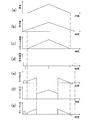
- the graph which shows the relationship between vehicle speed, operation amount, throttle opening, angular acceleration, motor output, engine output, and duty ratio.
- the enlarged view of the clutch apparatus which concerns on a modification.
- a hybrid motorcycle 200 includes an electric motor 101, an engine 102, a continuously variable transmission 103, a final gear 104, drive wheels 105, a throttle grip 106, a position sensor 107, a vehicle speed.
- a sensor 108 and a power transmission device are provided.
- the power transmission device includes a clutch device 100 and a control unit 109.
- the electric motor 101 is one of the drive sources of the hybrid motorcycle according to this embodiment.
- the electric motor 101 rotationally drives the drive wheels 105 at the time of starting or sudden acceleration.
- the electric motor 101 is configured to start the engine 102. That is, the electric motor 101 is used as a cell motor when the engine 102 is started.
- the electric motor 101 is configured to be driven by the engine 102 to generate electric power. That is, the electric motor 101 is also used as a dynamo after the engine 102 is started.
- the engine 102 is one of the drive sources of the hybrid motorcycle according to this embodiment. That is, the hybrid motorcycle according to the present embodiment has two drive sources of the electric motor 101 and the engine 102.
- the engine 102 rotationally drives the drive wheels 105 during normal travel.
- the engine 102 rotates the drive wheels 105 and drives the electric motor 101 to generate electric power.
- the continuously variable transmission 103 is configured to shift torque from the electric motor 101 and the engine 102.
- the continuously variable transmission 103 is a belt type continuously variable transmission. That is, the hybrid motorcycle according to the present embodiment employs an automatic transmission.
- the continuously variable transmission 103 receives torque from the electric motor 101 and the engine 102.
- the continuously variable transmission 103 includes a driving pulley device, a driven pulley device, and a belt.
- the belt is hung between the driving pulley device and the driven pulley device. As the diameter of each pulley device changes, the gear ratio changes continuously.
- Clutch device 100 is configured to transmit torque from one of drive source and drive wheel 105 and to block torque transmission from the other of drive source and drive wheel 105.
- the clutch device 100 is configured to transmit torque from the electric motor 101 or engine 102 to the drive wheel 105 and to block torque transmission from the drive wheel 105 to the electric motor 101 or engine 102.
- the clutch device 100 is disposed between the continuously variable transmission 103 and the drive wheel 105.
- the clutch device 100 is disposed between the continuously variable transmission 103 and the final gear 104. Details of the clutch device 100 will be described below.
- the axial direction means the direction in which the rotation shaft O of the clutch device extends.
- the radial direction means the radial direction of a circle around the rotation axis O
- the circumferential direction means the circumferential direction of the circle around the rotation axis O.
- the inner side in the radial direction means a side close to the rotation axis O in the radial direction
- the outer side in the radial direction means a side far from the rotation axis O in the radial direction.
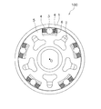
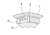
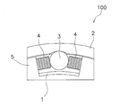
- the clutch device 100 includes an output member 1, an input member 2, a plurality of rollers 3 (an example of a transmission member), a plurality of pairs of urging members 4, a holding member 5, and a cam mechanism 6. It has.
- the output member 1 is connected to the drive wheel 105 side, and the input member 2 is connected to the electric motor 101 and the engine 102 side.
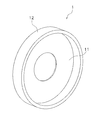
- the output member 1 is cylindrical.
- the output member 1 outputs torque to the drive wheel 105.
- the output member 1 can rotate around the rotation axis O.
- the output member 1 is arranged coaxially with the input member 2.
- the output member 1 is disposed at a distance from the input member 2 in the radial direction. Specifically, the output member 1 is disposed outside the input member 2 in the radial direction.
- the output member 1 has a disc portion 11 and a cylindrical portion 12.
- the cylindrical portion 12 is cylindrical and extends in the axial direction from the outer peripheral edge of the disc portion 11.
- the cylindrical portion 12 constitutes an outer wall of the clutch device 100.
- the output member 1 is made of, for example, carbon steel for machine structure, tool steel for machine structure, carbon tool steel, or alloy tool steel.
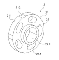
- the input member 2 is disposed inside the output member 1 in the radial direction. Specifically, the input member 2 is disposed inside the cylindrical portion 12 of the output member 1 in the radial direction. The input member 2 can rotate around the rotation axis O. Further, the input member 2 can be rotated relative to the output member 1. The input member 2 receives torque from the electric motor 101 or the engine 102.
- the input member 2 has an input member main body portion 21 and a boss portion 22.
- the input member 2 is made of, for example, carbon steel for machine structure, tool steel for machine structure, carbon tool steel, or alloy tool steel.
- the input member main body 21 has a disk shape.
- the outer peripheral surface 211 of the input member main body 21 is disposed with a gap from the inner peripheral surface of the output member 1. In a state where the roller 3, the urging member 4, and the holding member 5 are removed, the outer peripheral surface 211 of the input member main body 21 faces the inner peripheral surface of the output member 1.
- the inner peripheral surface of the output member 1 means the inner peripheral surface of the cylindrical portion 12 of the output member 1.
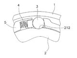
- a plurality of cam surfaces 212 are formed on the outer peripheral surface 211 of the input member main body 21.
- the cam surfaces 212 are formed at intervals in the circumferential direction.
- the cam surfaces 212 are arranged at equal intervals in the circumferential direction.
- Each cam surface 212 is configured to be recessed inward in the radial direction. The central portion of the cam surface 212 in the circumferential direction is farthest from the inner peripheral surface of the output member 1. Each cam surface 212 is configured to approach the output member 1 as it approaches both ends in the circumferential direction. Specifically, each cam surface 212 is formed in an arc shape when viewed in the axial direction.
- the input member main body 21 has a plurality of first through holes 213.
- Each first through hole 213 penetrates the input member main body 21 in the axial direction.
- the first through holes 213 are arranged at intervals in the circumferential direction.
- the first through holes 213 are arranged at equal intervals in the circumferential direction.
- Each first through hole 213 is arranged on the same circumference.
- Each first through-hole 213 has a long hole shape extending in the circumferential direction.
- the boss portion 22 is cylindrical and extends from the input member main body portion 21 in the axial direction.
- the boss portion 22 is arranged coaxially with the input member main body portion 21.
- the boss 22 has a smaller radius than the input member main body 21.
- the boss portion 22 is configured to engage with an input shaft (not shown) to which torque from the electric motor 101 or the engine 102 side is input.
- the boss portion 22 has a second through hole 221.
- the second through hole 221 is configured to engage the input shaft.
- the second through hole 221 has a pair of opposed flat surfaces on the inner peripheral surface.
- the input shaft has a pair of planes facing each other on the outer peripheral surface. With this configuration, the input shaft engages with the second through hole 221 and can rotate integrally.
- the second through hole 221 penetrates not only the boss portion 22 but also the input member main body portion 21.
- the holding member 5 holds the roller 3 between the input member 2.
- the holding member 5 holds the roller 3 in a non-engaged state in a steady state.
- the holding member 5 holds the roller 3 via the biasing member 4.
- the holding member 5 is disposed so as to be rotatable relative to the input member 2 and the output member 1.
- the holding member 5 is made of resin, and can be specifically formed of PA resin, POM resin, PPS resin, PBT resin, PEEK resin, PTFE resin, or the like.
- the holding member 5 is aligned with the input member 2 in the axial direction.
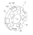
- the holding member 5 has a disk plate shape and has a third through hole 51 at the center thereof.
- the holding member 5 includes a holding member main body portion 52 and a holding portion 53.
- the holding member body 52 is disk-shaped and has a third through hole 51 in the center.
- the third through hole 51 penetrates the holding member main body 52 in the axial direction.
- the third through-hole 51 is circular when viewed in the axial direction.
- the boss portion 22 of the input member 2 passes through the third through hole 51 of the holding member 5.
- the boss portion 22 extends in the axial direction beyond the holding member 5 via the third through hole 51.
- the outer diameter of the boss portion 22 is smaller than the inner diameter of the third through hole 51.
- the holding member 5 is supported by the input member 2 by the inner peripheral surface of the third through hole 51 coming into contact with the outer peripheral surface of the boss portion 22.
- the upper end portion of the inner peripheral surface of the third through hole 51 and the upper end portion of the outer peripheral surface of the boss portion 22 are in contact with each other.
- the holding member main body 52 has a plurality of fourth through holes 521.
- the fourth through holes 521 are arranged at intervals in the circumferential direction.
- the fourth through holes 521 are arranged at equal intervals in the circumferential direction.
- the holding portion 53 is configured to hold the roller 3 and the biasing member 4 in the circumferential direction.
- the holding portion 53 is cylindrical and extends from the holding member main body portion 52 in the axial direction.
- the holding portion 53 is disposed between the output member 1 and the input member 2 in the radial direction.
- the holding portion 53 is disposed between the cylindrical portion 12 of the output member 1 and the input member main body portion 21 of the input member 2 in the radial direction.
- the holding part 53 has a plurality of fifth through holes 531.
- Each fifth through hole 531 penetrates the holding portion 53 in the radial direction. For this reason, in a state where the roller 3 and the pair of biasing members 4 are removed, the output member 1 and the input member 2 face each other through the fifth through hole 531.
- Each fifth through-hole 531 is arranged with a gap in the circumferential direction.
- the fifth through holes 531 are arranged at equal intervals in the circumferential direction.
- Each fifth through-hole 531 is composed of a pair of inner wall surfaces.
- the pair of inner wall surfaces constitute a holding surface 532.
- the pair of holding surfaces 532 face each other in the circumferential direction.
- the pair of holding surfaces 532 hold the roller 3 and the pair of urging members 4.
- roller 3 As shown in FIGS. 2 and 3, the roller 3 is held by a holding member 5. Specifically, the roller 3 is held by the holding member 5 via a pair of urging members 4. The roller 3 is disposed in the fifth through hole 531 of the holding member 5.
- Each roller 3 has a cylindrical shape extending in the axial direction.
- the roller 3 is disposed between the output member 1 and the input member 2 in the radial direction.
- the roller 3 is disposed between the cylindrical portion 12 of the output member 1 and the input member main body portion 21 in the radial direction.
- the roller 3 can be engaged and disengaged.
- the disengaged state refers to a state in which the roller 3 blocks transmission of torque from the input member 2 to the output member 1. That is, in the non-engaged state, the roller 3 is not engaged between the output member 1 and the input member 2.
- the roller 3 is urged by the urging member 4 so as to be positioned at the center portion of the cam surface 212 in the circumferential direction and to be in contact with the input member.
- the roller 3 is arrange
- the engaged state refers to a state in which the roller 3 transmits torque from the input member 2 to the output member 1. That is, in the engaged state, the roller 3 is in a state of being meshed between the output member 1 and the input member 2. In addition, the roller 3 is located in the position which moved to either of the both ends from the center part of the cam surface 212, when it exists in an engagement state. The roller 3 is in contact with the output member 1.
- the biasing member 4 is disposed in the fifth through hole 531.
- the urging member 4 urges the roller 3 in a non-engaged state.
- the pair of urging members 4 are configured to urge one roller 3 from the circumferential direction toward the input member 2 side.
- the urging member 4 has a first end and a second end in the circumferential direction.
- the first end portion that contacts the roller 3 is disposed on the inner side in the radial direction than the second end portion that contacts the holding surface 532.
- the urging member 4 is held by a holding member 5.
- the urging member 4 may be, for example, a leaf spring or a coil spring.
- the cam mechanism 6 is configured to engage the roller 3 between the output member 1 and the input member 2 by an inertial force generated when the input member 2 rotates relative to the holding member 5.
- the cam mechanism 6 has a cam surface 212 formed on the outer peripheral surface of the input member 2 (see FIG. 7).
- the interval between the cam surface 212 formed on the outer peripheral surface of the input member 2 and the inner peripheral surface of the output member 1 is different in the rotation direction.
- the interval near the center of the cam surface 212 in the circumferential direction is larger than the diameter of the roller 3, and the interval near both ends of the cam surface 212 in the circumferential direction is smaller than the diameter of the roller 3.
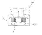
- the clutch device 100 configured as described above is applied to a motorcycle, for example, and operates as follows when the motorcycle starts. First, in a state where no torque is input from a drive source such as the electric motor 101 or the engine 102, the roller 3 is in a disengaged state as shown in FIG. That is, the roller 3 is located at the center of the cam surface 212 and is not engaged between the output member 1 and the input member 2. For this reason, even if torque is input from the output member 1, it is not transmitted to the input member 2. For example, when it is desired to push and move the stopped hybrid motorcycle 200, even if the driving wheel 105 rotates by pushing the hybrid motorcycle 200, only the output member 1 rotates and the input member 2 does not rotate.
- the electric motor 101 or the engine 102 is not rotated. That is, the clutch device 100 blocks torque transmission from the drive wheel 105 to the continuously variable transmission 103. As a result, the hybrid motorcycle 200 can be easily moved. Note that the arrows in FIG. 7 indicate the rotation direction of the output member 1.
- the input member 2 rotates.
- the holding member 5 holding the roller 3 between the input member 2 rotates. Since the rotation speed of the holding member 5 is slower than that of the input member 2 due to inertia, the holding member 5 rotates relative to the input member 2 due to inertial force.
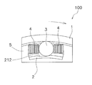
- the holding member 5 has a rotational speed faster than that of the input member 2 due to inertia when the roller 3 is in an engaged state and the vehicle is traveling, and therefore the holding member 5 is It rotates relative to the input member 2 by inertial force. Then, as shown in FIG. 9, the roller 3 is engaged, and the roller 3 meshes between the output member 1 and the input member 2. As a result, the output member 1 and the input member 2 rotate integrally. That is, torque is transmitted from the input member 2 to the output member 1 through each roller 3. Therefore, the clutch device 100 transmits the torque from the continuously variable transmission 103 to the drive wheels 105. 9 indicates the rotation direction of the clutch device 100.
- the holding member 5 rotates relative to the input member 2 by inertial force.
- the roller 3 meshes between the output member 1 and the input member 2, and torque is transmitted between the output member 1 and the input member 2.
- the roller 3 is engaged.
- the holding member main body portion 52 of the holding member 5 has a disk-like plate shape extending from the boss portion 22 to the output member 1.
- the contact point between the input member 2 and the holding member 5 is set to a radius. Bring inside the direction. Specifically, the boss portion 22 of the input member 2 and the inner peripheral surface of the third through hole 51 of the holding member 5 are brought into contact with each other.
- the final gear 104 is disposed between the clutch device 100 and the drive wheel 105. Specifically, the final gear 104 is provided between a drive shaft (not shown) and the drive wheel 105. Examples of the final gear 104 include a three-axis reduction mechanism that combines a spur gear or a helical gear, and a one-axis reduction mechanism that uses a planetary gear.
- the drive wheels 105 are wheels that rotate by receiving torque from the electric motor 101 and the engine 102.
- the rear wheels are the drive wheels 105.
- the throttle grip 106 is operated by the driver.
- the throttle opening is adjusted by operating the throttle grip 106.
- the driver operates the throttle grip 106 by rotating the throttle grip 106.
- the throttle opening increases as the rotation angle of the throttle grip 106 increases. That is, as the operation amount (rotation angle) of the throttle grip 106 increases, the output of the engine increases and the vehicle speed increases. Further, as the operation amount (rotation angle) of the throttle grip 106 increases, the output of the electric motor 101 increases and the vehicle speed increases.
- the throttle grip 106 corresponds to an operated portion that receives an operation related to the vehicle speed. That is, the throttle grip 106 corresponds to the operated portion of the present invention.
- the position sensor 107 is configured to detect an operation amount of the throttle grip 106.
- the position sensor 107 is configured to detect the rotation angle of the throttle grip 106.
- the position sensor 107 outputs a signal related to the operation amount of the throttle grip 106 to the control unit 109.
- the position sensor 107 corresponds to an operation amount detection unit that detects an operation amount of the operated unit. That is, the position sensor 107 corresponds to the operation amount detection unit of the present invention.
- the vehicle speed sensor 108 is configured to detect the vehicle speed of the hybrid motorcycle 200. Specifically, the vehicle speed sensor 108 is configured to detect the rotational speed of the drive wheel 105. The vehicle speed sensor 108 outputs a signal related to the vehicle speed to the control unit 109.
- Control unit 109 indirectly controls the clutch device 100 by controlling the electric motor 101.
- the control unit 109 is configured to control the electric motor 101 based on the operation amount detected by the position sensor 107 and the vehicle speed detected by the vehicle speed sensor 108.
- the control unit 109 rotates the input member 2 at an angular acceleration that rotates relative to the holding member 5 based on the state of the hybrid motorcycle 200. Specifically, the control unit 109 controls the electric motor 101 when the throttle grip 106 is operated in a state where the vehicle speed is 0, and inputs the angular acceleration so as to rotate relative to the holding member 5 of the clutch device 100. The member 2 is rotated.
- FIG. 10 is a diagram illustrating time transition of various state values when performing a series of operations from starting the hybrid motorcycle 200 to stopping the vehicle.
- the following description is an illustration to the last and specific control content is not limited to this example.
- the term throttle opening used in the description below represents the ratio of the instantaneous value of the fuel injection amount to the maximum value during engine operation, while the throttle during engine operation during hybrid operation or single motor operation. It shall be equivalent to the opening.
- the driver turns on the motorcycle 200 so that the hybrid motorcycle 200 can run. Then, the driver operates the throttle grip 106, that is, rotates the throttle grip 106. As a result, the operation amount of the throttle grip 106 gradually increases as shown in FIG. That is, the rotation angle of the throttle grip 106 gradually increases. As shown in FIGS. 10a and 10c, the vehicle speed and the throttle opening start to increase after a predetermined time has elapsed from the start of operation of the throttle grip 106. That is, the throttle grip 106 has a play portion, and the throttle grip 106 operates the throttle opening with this play.
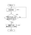
- each sensor starts to operate as shown in FIG. 11 (step S1). Specifically, the position sensor 107 detects the operation amount of the throttle grip 106. Then, the position sensor 107 outputs a signal related to this operation amount to the control unit 109.
- the vehicle speed sensor 108 detects the vehicle speed. The vehicle speed sensor 108 outputs a signal related to the vehicle speed to the control unit 109.
- control unit 109 detects that the vehicle speed is zero and the throttle grip 106 is operated based on signals from the position sensor 107 and the vehicle speed sensor 108 (the rotation angle of the throttle grip 106 is 0). It is determined whether or not (step S2).
- step S2 If the control unit 109 determines that the vehicle speed is not zero or the throttle grip 106 is not operated (the rotation angle of the throttle grip 106 is zero) (No in step S2), the process of step S1 is performed again. Repeat from.
- step S2 If the control unit 109 determines that the vehicle speed is zero and the throttle grip 106 has been operated (the rotation angle of the throttle grip 106 is greater than zero) (Yes in step S2), the control unit 109 sets the first electric motor 101 to the first state. Control is performed in the control mode (step S3). Specifically, as shown in FIGS. 10E and 10G, the control unit 109 changes the control signal so as to instantaneously increase the output of the electric motor 101 in the first control mode. For example, when the electric motor 101 is subjected to switching control, the control unit 109 temporarily increases the duty ratio of the control signal. Thereby, the motor output of the electric motor 101 increases.
- the output of the electric motor 101 controlled by the control unit 109 rotates the input member 2 of the clutch device 100 (FIG. 10 (d)). Thereby, the angular acceleration of the input member 2 increases, and the input member 2 rotates relative to the holding member 5. Then, due to the inertial force due to the relative rotation of the holding member 5, the roller 3 is brought into an engaged state as shown in FIG. In the process of step S3, the control unit 109 outputs the electric motor 101 so that the input member 2 rotates at a preset angular acceleration regardless of the operation amount of the throttle grip 106.
- the output of the electric motor 101 is set to be smaller than the torque necessary for starting the hybrid motorcycle 200.
- the roller 3 is reliably engaged between the output member 1 and the input member 2.
- the input member 2 is reversely rotated with respect to the output member 1 while the centrifugal force is hardly applied to the roller 3 as in the stationary state, and the direction in which the meshing of the roller 3 is released. It is necessary to generate the inertia force. The meshing state is not released simply by reducing the motor output. For this reason, even when the driver operates the throttle grip 106 slowly, the roller 3 is reliably engaged between the output member 1 and the input member 2.
- step S3 ends after the roller 3 is engaged between the output member 1 and the input member 2.
- the process in step S3 may be terminated after a predetermined time has elapsed. Further, when the driver suddenly operates the throttle grip 106, it is not always necessary to cause the control unit 109 to operate in the first control mode.
- the drive wheels 105 are driven by the electric motor 101 when starting and when traveling at a low and medium speed. That is, torque from the electric motor 101 is transmitted to the drive wheel 105 via the continuously variable transmission 103, the clutch device 100, and the final gear 104.
- the drive wheels 105 are driven by torque from the engine 102 during normal travel. That is, torque from the engine 102 is transmitted to the drive wheels 105 via the continuously variable transmission 103, the clutch device 100, and the final gear 104.
- the electric motor 101 may be caused to generate electric power by the torque of the engine 102. That is, the electric motor 101 is caused to function as a dynamo.
- the electric power generated by the electric motor 101 is stored in a battery (not shown).
- the engine 102 is started by the electric motor 101. That is, the electric motor 101 functions as a cell motor.
- the vehicle speed sensor 108 detects the vehicle speed (step S ⁇ b> 11) and outputs a signal related to the vehicle speed to the control unit 109.
- the control unit 109 determines whether or not the vehicle speed is zero based on a signal from the vehicle speed sensor 108 in a traveling state where the vehicle speed is greater than zero (step S12). If the control unit 109 determines that the vehicle speed is not zero (No in step S12), the control unit 109 repeats the process from step S11 again.
- Step S13 the control unit 109 controls the electric motor 101 in the second control mode. Specifically, in the hybrid motorcycle 200 that has stopped after being decelerated, the roller 3 maintains a state in which it is engaged between the output member 1 and the input member 2. That is, as shown in FIG. 9, the roller 3 is in an engaged state.
- the control unit 109 controls the electric motor 101 in the second control mode, and changes the control signal so as to instantaneously increase the output of the electric motor.
- the input member 2 is rotated relative to the holding member 5 so that the electric motor 101 releases the meshing of the roller 3 between the output member 1 and the input member 2.
- the roller 3 is brought into a non-engaged state as shown in FIG. 7 by the inertial force due to the relative rotation of the holding member 5.
- the input torque transmission of a clutch apparatus can be interrupted
- step S13 the control unit 109 outputs the electric motor 101 so that the input member 2 rotates at a preset angular acceleration.
- the output of the electric motor 101 is set to be smaller than the torque necessary for starting the hybrid motorcycle 200.
- the processing in step S13 is controlled so as to end when the roller 3 is in a disengaged state. For example, after a predetermined time has elapsed, the process of step S13 ends.
- one roller 3 is urged by a pair of urging members 4, but the configuration is not limited to this.
- one roller 3 may be urged by one urging member 4.
- the roller 3 is sandwiched between the urging member 4 and the holding surface 532 of the holding member 5 in the circumferential direction.
- the urging member 4 may be disposed on the first direction side with respect to the roller 3 or may be disposed on the second direction side.
- the roller 3 and the biasing member 4 are in direct contact with each other, but the present invention is not limited to this configuration.
- the urging member 4 may have a spring seat 7 attached to the end on the side in contact with the roller 3.
- the holding member 5 may include a cover portion 54 that covers the outer peripheral sides of the biasing member 4 and the spring seat 7. By providing the cover part 54, the cover part 54 does not come into sliding contact with the output member 1 on the outer periphery, and the position of the roller 3 can be appropriately maintained. This configuration can also be applied to the first modification.
- the cam surface 212 is formed in an arc shape when viewed in the axial direction, but the cam surface 212 may be formed in a V shape or may be formed in another shape.
- the roller 3 is engaged even if the holding member 5 rotates relative to the input member 2 in either the first direction or the second direction by inertial force.
- the configuration is limited to this configuration. Not. For example, as shown in FIG. 14, if the cam surface 212 has a gentle shape on the first direction side and a shape that conforms to the outer surface shape of the roller 3 on the second direction side, the holding member 5 has an inertial force. Thus, the roller 3 is engaged only when it rotates relative to the input member 2 in the first direction.
- the roller 3 does not rotate relative to the non-engaged state.
- the shape of the cam surface 212 is changed so that the first direction side and the second direction side are reversed, the roller only when the holding member 5 rotates relative to the input member 2 in the second direction due to inertial force. It can also comprise so that 3 may be in an engagement state. This configuration can also be applied to the first or second modification.
- the roller 3 is used as the transmission member.
- the transmission member may have another shape instead of the roller 3.
- a sprag 31 can be provided as a transmission member.
- the sprag 31 has a flat shape whose dimension in the radial direction of the clutch device changes due to rotation. Even when the sprag 31 is used, the sprag 31 is held with a gap with respect to the output member 1 in a non-coupled state, and the sprag 31 rotates and becomes engaged by the inertial force of the holding member 5. And the output member 1 may be configured to be engaged.
- the sprag 31 By using the sprag 31, it is not necessary to provide a cam surface on either the input member 2 or the output member 1, and the configuration of the input member 2 and the output member 1 is simplified.
- This configuration can be applied to any one of the first to third modifications.
- two sprags 31 may be arranged at both ends of one urging member 4. In this configuration, the sprag 31 can be brought into the engaged state even if the holding member 5 rotates relative to the input member 2 in either the first direction or the second direction due to inertial force.
- the input member 2 is provided on the inner peripheral side and the output member 1 is provided on the outer peripheral side.
- the arrangement of the input member 2 and the output member 1 may be reversed.
- the arrangement of the output member 1 and the input member 2 in the radial direction may be opposite to that in the above embodiment. That is, the output member 1 may be disposed inside the input member 2 in the radial direction.
- the transmission member 3 is urged toward the input member 2 and is disposed at a distance from the output member 1. This configuration can be applied to any one of the first to fourth modifications.
- the clutch device 100 is arranged between the continuously variable transmission 103 and the final gear 104, but the arrangement of the clutch device 100 is not limited to this.
- the clutch device 100 may be disposed between the drive wheel 105 and the final gear 104.
- the input shaft for inputting torque from the engine to the input member 2 and the second through hole 221 of the boss portion 22 may be engaged by spline fitting or other structures. Good.
- the input member main body 21 may not have the first through hole 213.
- the holding member 5 may not have the fourth through hole 521.
- control unit 109 rotates the input member 2 with the electric motor 101 for driving the drive wheels 105, but the present invention is not limited to this configuration.
- control unit 109 may rotate the input member 2 using an electric motor different from the electric motor 101 for driving the drive wheels 105.
- the transmission member 3 or the holding member is brought into direct contact with the transmission member 3 and the holding member 5.
- the biasing member 4 may bias both through 5.
- a bearing member may be interposed between the input member 2 and the holding member 5 so that the holding member 5 smoothly rotates relative to the input member 2.
Landscapes
- Engineering & Computer Science (AREA)
- Mechanical Engineering (AREA)
- General Engineering & Computer Science (AREA)
- Chemical & Material Sciences (AREA)
- Combustion & Propulsion (AREA)
- Transportation (AREA)
- Automation & Control Theory (AREA)
- Electric Propulsion And Braking For Vehicles (AREA)
- Hybrid Electric Vehicles (AREA)
Applications Claiming Priority (4)
| Application Number | Priority Date | Filing Date | Title |
|---|---|---|---|
| JP2017049774 | 2017-03-15 | ||
| JP2017-049774 | 2017-03-15 | ||
| JP2017-227753 | 2017-11-28 | ||
| JP2017227753 | 2017-11-28 |
Publications (1)
| Publication Number | Publication Date |
|---|---|
| WO2018168857A1 true WO2018168857A1 (ja) | 2018-09-20 |
Family
ID=63523136
Family Applications (1)
| Application Number | Title | Priority Date | Filing Date |
|---|---|---|---|
| PCT/JP2018/009746 Ceased WO2018168857A1 (ja) | 2017-03-15 | 2018-03-13 | 動力伝達装置、及び自動二輪車 |
Country Status (2)
| Country | Link |
|---|---|
| JP (1) | JP6792585B2 (enExample) |
| WO (1) | WO2018168857A1 (enExample) |
Cited By (3)
| Publication number | Priority date | Publication date | Assignee | Title |
|---|---|---|---|---|
| CN111605553A (zh) * | 2019-02-26 | 2020-09-01 | 郑州宇通客车股份有限公司 | 一种新能源汽车扭矩分段梯度滤波控制方法及装置 |
| CN111959673A (zh) * | 2020-08-31 | 2020-11-20 | 洛阳北方易初摩托车有限公司 | 一种摩托车混动控制方法及系统 |
| JP2020196387A (ja) * | 2019-06-04 | 2020-12-10 | 朝日電装株式会社 | スロットルグリップ装置 |
Families Citing this family (1)
| Publication number | Priority date | Publication date | Assignee | Title |
|---|---|---|---|---|
| JP7734210B2 (ja) * | 2021-12-15 | 2025-09-04 | 本田技研工業株式会社 | 断続装置 |
Citations (8)
| Publication number | Priority date | Publication date | Assignee | Title |
|---|---|---|---|---|
| JPH06344797A (ja) * | 1993-06-08 | 1994-12-20 | Ntn Corp | 4輪駆動車の回転伝達装置 |
| DE10015974A1 (de) * | 2000-03-30 | 2001-10-04 | Stieber Gmbh | Pyrotechnischer Gurtstraffer mit lösbarer Kupplung |
| JP2005137169A (ja) * | 2003-10-31 | 2005-05-26 | Nissan Motor Co Ltd | 車両の駆動力制御装置 |
| JP2006234034A (ja) * | 2005-02-23 | 2006-09-07 | Ntn Corp | 逆入力遮断クラッチ |
| JP2012122501A (ja) * | 2010-12-06 | 2012-06-28 | Ntn Corp | 遊星歯車機構およびこれを備えた電動補助自転車用のハブモータ装置 |
| JP2012215250A (ja) * | 2011-03-31 | 2012-11-08 | Honda Motor Co Ltd | 変速クラッチ制御装置 |
| JP2013053644A (ja) * | 2011-09-01 | 2013-03-21 | Nissan Motor Co Ltd | ワンウェイクラッチ |
| JP2013148176A (ja) * | 2012-01-20 | 2013-08-01 | Univance Corp | 動力伝達装置 |
Family Cites Families (6)
| Publication number | Priority date | Publication date | Assignee | Title |
|---|---|---|---|---|
| JP2992846B2 (ja) * | 1991-06-13 | 1999-12-20 | 愛知機械工業株式会社 | 2方向差動クラッチ |
| US5307911A (en) * | 1993-08-10 | 1994-05-03 | Inuktun Services Ltd. | Two-way clutch |
| US6000512A (en) * | 1997-07-30 | 1999-12-14 | Dana Corporation | Overrunning clutch with spring energized cage centering device |
| JP2007210399A (ja) * | 2006-02-08 | 2007-08-23 | Ntn Corp | 車両のモータ駆動回転伝達制御装置 |
| WO2007119360A1 (ja) * | 2006-03-16 | 2007-10-25 | Kawasaki Jukogyo Kabushiki Kaisha | 車両および車両用のモータ制御装置 |
| JP2010018101A (ja) * | 2008-07-09 | 2010-01-28 | Ntn Corp | ハイブリッド車両の駆動力伝達装置 |
-
2018
- 2018-03-09 JP JP2018043611A patent/JP6792585B2/ja active Active
- 2018-03-13 WO PCT/JP2018/009746 patent/WO2018168857A1/ja not_active Ceased
Patent Citations (8)
| Publication number | Priority date | Publication date | Assignee | Title |
|---|---|---|---|---|
| JPH06344797A (ja) * | 1993-06-08 | 1994-12-20 | Ntn Corp | 4輪駆動車の回転伝達装置 |
| DE10015974A1 (de) * | 2000-03-30 | 2001-10-04 | Stieber Gmbh | Pyrotechnischer Gurtstraffer mit lösbarer Kupplung |
| JP2005137169A (ja) * | 2003-10-31 | 2005-05-26 | Nissan Motor Co Ltd | 車両の駆動力制御装置 |
| JP2006234034A (ja) * | 2005-02-23 | 2006-09-07 | Ntn Corp | 逆入力遮断クラッチ |
| JP2012122501A (ja) * | 2010-12-06 | 2012-06-28 | Ntn Corp | 遊星歯車機構およびこれを備えた電動補助自転車用のハブモータ装置 |
| JP2012215250A (ja) * | 2011-03-31 | 2012-11-08 | Honda Motor Co Ltd | 変速クラッチ制御装置 |
| JP2013053644A (ja) * | 2011-09-01 | 2013-03-21 | Nissan Motor Co Ltd | ワンウェイクラッチ |
| JP2013148176A (ja) * | 2012-01-20 | 2013-08-01 | Univance Corp | 動力伝達装置 |
Cited By (5)
| Publication number | Priority date | Publication date | Assignee | Title |
|---|---|---|---|---|
| CN111605553A (zh) * | 2019-02-26 | 2020-09-01 | 郑州宇通客车股份有限公司 | 一种新能源汽车扭矩分段梯度滤波控制方法及装置 |
| CN111605553B (zh) * | 2019-02-26 | 2021-10-29 | 郑州宇通客车股份有限公司 | 一种新能源汽车扭矩分段梯度滤波控制方法及装置 |
| JP2020196387A (ja) * | 2019-06-04 | 2020-12-10 | 朝日電装株式会社 | スロットルグリップ装置 |
| JP7337340B2 (ja) | 2019-06-04 | 2023-09-04 | 朝日電装株式会社 | スロットルグリップ装置 |
| CN111959673A (zh) * | 2020-08-31 | 2020-11-20 | 洛阳北方易初摩托车有限公司 | 一种摩托车混动控制方法及系统 |
Also Published As
| Publication number | Publication date |
|---|---|
| JP2019085089A (ja) | 2019-06-06 |
| JP6792585B2 (ja) | 2020-11-25 |
Similar Documents
| Publication | Publication Date | Title |
|---|---|---|
| WO2018168857A1 (ja) | 動力伝達装置、及び自動二輪車 | |
| JP2017132440A (ja) | 自転車用駆動装置 | |
| WO2011030689A1 (ja) | 電気自動車 | |
| WO2012105198A1 (ja) | 電動自転車 | |
| JP2005059791A (ja) | 減速駆動装置 | |
| WO2011093425A1 (ja) | 動力伝達装置 | |
| JP7431675B2 (ja) | 駆動制御装置 | |
| WO2001042687A1 (en) | Range switching device | |
| JP2019085089A5 (enExample) | ||
| CN100581898C (zh) | 车辆用转向装置 | |
| US7093683B2 (en) | All-terrain vehicle | |
| WO2014175049A1 (ja) | 無段変速機 | |
| US20250305546A1 (en) | Two-speed transmission | |
| WO2018168851A1 (ja) | クラッチ装置 | |
| JP2010018101A (ja) | ハイブリッド車両の駆動力伝達装置 | |
| JP2014145421A (ja) | トルクリミッタ及び車両の駆動源制御装置 | |
| JP6892766B2 (ja) | 自動二輪車用動力伝達システム | |
| JP6040572B2 (ja) | 駆動力伝達制御装置 | |
| CN110549848B (zh) | 驱动装置和具有该驱动装置的车辆 | |
| JP2009078754A (ja) | ハイブリッド車両における駆動力伝達装置の制御方法 | |
| JP5942877B2 (ja) | ベルト式無段変速機の制御装置 | |
| JPH0678417A (ja) | 電気モータを用いた車輌における駆動伝達装置 | |
| US20260009431A1 (en) | Electric friction engagement device, method for detecting touch point therefor, and method for detecting abnormality thereof | |
| JP7093258B2 (ja) | トルクベクタリング装置 | |
| JP4608394B2 (ja) | 差動制限機構付き差動装置における電動モータの初期停止位置設定方法 |
Legal Events
| Date | Code | Title | Description |
|---|---|---|---|
| 121 | Ep: the epo has been informed by wipo that ep was designated in this application |
Ref document number: 18766624 Country of ref document: EP Kind code of ref document: A1 |
|
| NENP | Non-entry into the national phase |
Ref country code: DE |
|
| 122 | Ep: pct application non-entry in european phase |
Ref document number: 18766624 Country of ref document: EP Kind code of ref document: A1 |