WO2018168376A1 - グリップセンサ、ステアリングホイールおよび車両 - Google Patents
グリップセンサ、ステアリングホイールおよび車両 Download PDFInfo
- Publication number
- WO2018168376A1 WO2018168376A1 PCT/JP2018/006342 JP2018006342W WO2018168376A1 WO 2018168376 A1 WO2018168376 A1 WO 2018168376A1 JP 2018006342 W JP2018006342 W JP 2018006342W WO 2018168376 A1 WO2018168376 A1 WO 2018168376A1
- Authority
- WO
- WIPO (PCT)
- Prior art keywords
- sensor
- rim
- steering wheel
- line
- base material
- Prior art date
- Legal status (The legal status is an assumption and is not a legal conclusion. Google has not performed a legal analysis and makes no representation as to the accuracy of the status listed.)
- Ceased
Links
Images


Classifications
-
- B—PERFORMING OPERATIONS; TRANSPORTING
- B62—LAND VEHICLES FOR TRAVELLING OTHERWISE THAN ON RAILS
- B62D—MOTOR VEHICLES; TRAILERS
- B62D1/00—Steering controls, i.e. means for initiating a change of direction of the vehicle
- B62D1/02—Steering controls, i.e. means for initiating a change of direction of the vehicle vehicle-mounted
- B62D1/04—Hand wheels
- B62D1/046—Adaptations on rotatable parts of the steering wheel for accommodation of switches
-
- B—PERFORMING OPERATIONS; TRANSPORTING
- B60—VEHICLES IN GENERAL
- B60W—CONJOINT CONTROL OF VEHICLE SUB-UNITS OF DIFFERENT TYPE OR DIFFERENT FUNCTION; CONTROL SYSTEMS SPECIALLY ADAPTED FOR HYBRID VEHICLES; ROAD VEHICLE DRIVE CONTROL SYSTEMS FOR PURPOSES NOT RELATED TO THE CONTROL OF A PARTICULAR SUB-UNIT
- B60W50/00—Details of control systems for road vehicle drive control not related to the control of a particular sub-unit, e.g. process diagnostic or vehicle driver interfaces
- B60W50/08—Interaction between the driver and the control system
- B60W50/14—Means for informing the driver, warning the driver or prompting a driver intervention
-
- B—PERFORMING OPERATIONS; TRANSPORTING
- B60—VEHICLES IN GENERAL
- B60K—ARRANGEMENT OR MOUNTING OF PROPULSION UNITS OR OF TRANSMISSIONS IN VEHICLES; ARRANGEMENT OR MOUNTING OF PLURAL DIVERSE PRIME-MOVERS IN VEHICLES; AUXILIARY DRIVES FOR VEHICLES; INSTRUMENTATION OR DASHBOARDS FOR VEHICLES; ARRANGEMENTS IN CONNECTION WITH COOLING, AIR INTAKE, GAS EXHAUST OR FUEL SUPPLY OF PROPULSION UNITS IN VEHICLES
- B60K35/00—Instruments specially adapted for vehicles; Arrangement of instruments in or on vehicles
- B60K35/60—Instruments characterised by their location or relative disposition in or on vehicles
-
- B—PERFORMING OPERATIONS; TRANSPORTING
- B62—LAND VEHICLES FOR TRAVELLING OTHERWISE THAN ON RAILS
- B62D—MOTOR VEHICLES; TRAILERS
- B62D1/00—Steering controls, i.e. means for initiating a change of direction of the vehicle
- B62D1/02—Steering controls, i.e. means for initiating a change of direction of the vehicle vehicle-mounted
- B62D1/04—Hand wheels
- B62D1/06—Rims, e.g. with heating means; Rim covers
-
- G—PHYSICS
- G01—MEASURING; TESTING
- G01B—MEASURING LENGTH, THICKNESS OR SIMILAR LINEAR DIMENSIONS; MEASURING ANGLES; MEASURING AREAS; MEASURING IRREGULARITIES OF SURFACES OR CONTOURS
- G01B7/00—Measuring arrangements characterised by the use of electric or magnetic techniques
-
- G—PHYSICS
- G01—MEASURING; TESTING
- G01V—GEOPHYSICS; GRAVITATIONAL MEASUREMENTS; DETECTING MASSES OR OBJECTS; TAGS
- G01V3/00—Electric or magnetic prospecting or detecting; Measuring magnetic field characteristics of the earth, e.g. declination, deviation
- G01V3/08—Electric or magnetic prospecting or detecting; Measuring magnetic field characteristics of the earth, e.g. declination, deviation operating with magnetic or electric fields produced or modified by objects or geological structures or by detecting devices
-
- B—PERFORMING OPERATIONS; TRANSPORTING
- B60—VEHICLES IN GENERAL
- B60K—ARRANGEMENT OR MOUNTING OF PROPULSION UNITS OR OF TRANSMISSIONS IN VEHICLES; ARRANGEMENT OR MOUNTING OF PLURAL DIVERSE PRIME-MOVERS IN VEHICLES; AUXILIARY DRIVES FOR VEHICLES; INSTRUMENTATION OR DASHBOARDS FOR VEHICLES; ARRANGEMENTS IN CONNECTION WITH COOLING, AIR INTAKE, GAS EXHAUST OR FUEL SUPPLY OF PROPULSION UNITS IN VEHICLES
- B60K2360/00—Indexing scheme associated with groups B60K35/00 or B60K37/00 relating to details of instruments or dashboards
- B60K2360/77—Instrument locations other than the dashboard
- B60K2360/782—Instrument locations other than the dashboard on the steering wheel
-
- B—PERFORMING OPERATIONS; TRANSPORTING
- B60—VEHICLES IN GENERAL
- B60K—ARRANGEMENT OR MOUNTING OF PROPULSION UNITS OR OF TRANSMISSIONS IN VEHICLES; ARRANGEMENT OR MOUNTING OF PLURAL DIVERSE PRIME-MOVERS IN VEHICLES; AUXILIARY DRIVES FOR VEHICLES; INSTRUMENTATION OR DASHBOARDS FOR VEHICLES; ARRANGEMENTS IN CONNECTION WITH COOLING, AIR INTAKE, GAS EXHAUST OR FUEL SUPPLY OF PROPULSION UNITS IN VEHICLES
- B60K35/00—Instruments specially adapted for vehicles; Arrangement of instruments in or on vehicles
- B60K35/20—Output arrangements, i.e. from vehicle to user, associated with vehicle functions or specially adapted therefor
- B60K35/21—Output arrangements, i.e. from vehicle to user, associated with vehicle functions or specially adapted therefor using visual output, e.g. blinking lights or matrix displays
- B60K35/22—Display screens
-
- B—PERFORMING OPERATIONS; TRANSPORTING
- B60—VEHICLES IN GENERAL
- B60W—CONJOINT CONTROL OF VEHICLE SUB-UNITS OF DIFFERENT TYPE OR DIFFERENT FUNCTION; CONTROL SYSTEMS SPECIALLY ADAPTED FOR HYBRID VEHICLES; ROAD VEHICLE DRIVE CONTROL SYSTEMS FOR PURPOSES NOT RELATED TO THE CONTROL OF A PARTICULAR SUB-UNIT
- B60W50/00—Details of control systems for road vehicle drive control not related to the control of a particular sub-unit, e.g. process diagnostic or vehicle driver interfaces
- B60W50/08—Interaction between the driver and the control system
- B60W50/14—Means for informing the driver, warning the driver or prompting a driver intervention
- B60W2050/146—Display means
-
- B—PERFORMING OPERATIONS; TRANSPORTING
- B60—VEHICLES IN GENERAL
- B60W—CONJOINT CONTROL OF VEHICLE SUB-UNITS OF DIFFERENT TYPE OR DIFFERENT FUNCTION; CONTROL SYSTEMS SPECIALLY ADAPTED FOR HYBRID VEHICLES; ROAD VEHICLE DRIVE CONTROL SYSTEMS FOR PURPOSES NOT RELATED TO THE CONTROL OF A PARTICULAR SUB-UNIT
- B60W2540/00—Input parameters relating to occupants
- B60W2540/18—Steering angle
-
- B—PERFORMING OPERATIONS; TRANSPORTING
- B62—LAND VEHICLES FOR TRAVELLING OTHERWISE THAN ON RAILS
- B62D—MOTOR VEHICLES; TRAILERS
- B62D1/00—Steering controls, i.e. means for initiating a change of direction of the vehicle
- B62D1/02—Steering controls, i.e. means for initiating a change of direction of the vehicle vehicle-mounted
- B62D1/04—Hand wheels
- B62D1/06—Rims, e.g. with heating means; Rim covers
- B62D1/065—Steering wheels with heating and ventilating means
Definitions
- the present invention relates to a grip sensor that detects gripping of a steering wheel of a vehicle, for example.
- Patent Document 1 a grip sensor that detects gripping of a steering wheel of a vehicle has been proposed (see, for example, Patent Document 1).
- the present invention provides a grip sensor that suppresses the occurrence of false detection.
- the grip sensor includes a base material, a sensor wire, and a sensor circuit.
- the substrate is attached to a rim of a steering wheel.
- the sensor line is disposed on the base material and has a first end and a second end positioned opposite to the first end.
- the sensor circuit is electrically connected to the first end of the sensor line.
- the sensor line includes a first line portion and a second line portion positioned in the direction of the second end with respect to the first line portion.
- the second line portion is opposed to the seat surface of the rim closer to the seat surface of the vehicle seat than the first line portion. Placed in the section.
- the first line portion is disposed in a non-facing portion that is a portion other than the seating surface facing portion in the rim.
- the grip sensor of the present invention can suppress the occurrence of false detection.
- FIG. 1 is a diagram illustrating an example of a vehicle compartment in which a grip sensor according to an embodiment is arranged.
- FIG. 2 is a diagram illustrating a configuration example of the grip sensor in the embodiment.
- FIG. 3 is a diagram illustrating an example of a cross section of a rim to which the sensor unit according to the embodiment is attached.
- FIG. 4 is a diagram illustrating a state in which the sensor unit is attached to the rim of the steering wheel in the embodiment.
- FIG. 5 is a diagram for explaining the positional relationship between the rim of the steering wheel and the driver in the embodiment.
- FIG. 6 is a diagram illustrating the relationship between the position on the sensor line and the detection sensitivity of gripping at that position.
- FIG. 1 is a diagram illustrating an example of a vehicle compartment in which a grip sensor according to an embodiment is arranged.
- FIG. 2 is a diagram illustrating a configuration example of the grip sensor in the embodiment.
- FIG. 3 is a diagram illustrating an example of a
- FIG. 7 is a diagram illustrating an example of the first sensor unit or the second sensor unit according to the first modification of the embodiment.
- FIG. 8 is a diagram for explaining the positional relationship between the rim of the steering wheel and the driver according to the second modification of the embodiment.
- FIG. 9 is a diagram illustrating a configuration example of a grip sensor according to a third modification of the embodiment.
- FIG. 10 is a diagram illustrating a configuration example of a grip sensor according to Modification 4 of the embodiment.
- the grip sensor has a base material and a sensor wire provided on the base material.
- the base material on which such sensor wires are arranged is wound around, for example, a steering wheel.
- the outer peripheral surface located at the lower part of the steering wheel faces the knee or thigh of the driver who operates the steering wheel.
- the capacitance of the sensor line changes due to the approach of the driver's knee or thigh to the outer peripheral surface, and the grip sensor detects gripping even though the driver is not gripping the steering wheel. May end up.
- the grip sensor includes a base material, a sensor wire, and a sensor circuit.
- the substrate is attached to a rim of a steering wheel.
- the sensor line is disposed on the base material and has a first end and a second end positioned opposite to the first end.
- the sensor circuit is electrically connected to the first end of the sensor line.
- the sensor line includes a first line portion and a second line portion positioned in the direction of the second end with respect to the first line portion.
- the first line portion is disposed in a non-facing portion that is a portion other than the seating surface facing portion in the rim.
- the seat surface facing portion is located on the outer peripheral surface of the rim that is on the outermost side in the direction from the rotation center of the steering wheel toward the rim.
- the non-facing portion may include the front surface and the back surface of the rim.
- the seating surface facing portion is disposed on the back surface of the rim, and the non-facing portion is configured with the front surface of the rim, and
- the rim may include an outermost outer peripheral surface in a direction from the rotation center of the steering wheel toward the rim.
- the second line portion may be disposed over the outer periphery of the rim in a cross section parallel to the rotation axis of the steering wheel at the seating surface facing portion when the steering wheel is in the neutral state. Good.
- the second line portion that is far from the sensor circuit in the electrical connection path is disposed at the seating surface facing portion of the rim of the steering wheel. It can be made lower than the detection sensitivity at the facing portion. As a result, it is possible to suppress erroneous detection of the steering wheel gripping by the driver due to the driver's knee or thigh approaching the seat surface facing portion of the rim.
- each of the first line portion and the second line portion may be arranged on the base material in a zigzag shape.
- the grip sensor may further include a power supply unit that is electrically connected to the second end of the sensor line and heats the sensor line by causing a current to flow through the sensor line.
- a steering wheel according to an aspect of the present invention includes the above-described grip sensor.
- a vehicle according to one embodiment of the present invention includes the above-described steering wheel.
- each figure is a schematic diagram and is not necessarily shown strictly. Moreover, in each figure, the same code
- expressions such as a substantially center or a substantially constant width are used. For example, substantially the same not only means that they are completely the same, but also means that they are substantially the same, that is, they contain an error of, for example, a few percent. The same applies to expressions using other “abbreviations”.
- FIG. 1 is a diagram illustrating an example of a vehicle compartment in which a grip sensor according to the present embodiment is arranged.
- the vehicle 1 includes a steering wheel 200, a speaker 301, and a display device 302 such as a liquid crystal display.
- the speaker 301 and the display device 302 are configured as an alerting device, for example.
- the steering wheel 200 is for steering the vehicle 1.
- the steering wheel 200 includes a rim 210 having a ring shape, a substantially T-shaped spoke 202 integrally formed on the inner peripheral surface of the rim 210, and a horn switch (not shown) disposed at the center of the spoke 202. And a horn switch cover 203 for covering the above.
- the grip sensor 100 is a device that detects gripping of the steering wheel 200 by a hand, and is provided in the steering wheel 200 of the vehicle 1 as shown in FIG. Specifically, the grip sensor 100 includes a sensor unit 110 embedded in the rim 210 of the steering wheel 200, a control circuit unit 120 that detects gripping based on a signal from the sensor unit 110, a sensor unit 110, and a control circuit. And a harness 130 for electrically connecting the portion 120. The control circuit unit 120 is embedded in the spoke 202, for example. Such a grip sensor 100 detects the grip of the rim 210 of the steering wheel 200.
- the measured capacitance changes depending on whether the driver of the vehicle 1 is holding the rim 210 of the steering wheel 200 or not.
- the control circuit unit 120 measures the capacitance of the sensor unit 110 or a value (change amount) corresponding to the capacitance, and detects gripping of the rim 210 by the driver's hand based on the value. .
- control circuit part 120 makes a warning device perform a warning to a driver, when grasping is not detected although vehicles 1 are driven.
- the speaker 301 of the alerting device alerts the driver with a warning sound or voice.
- the display device 302 displays a warning message that prompts the driver to hold the steering wheel 200 firmly. Thereby, a traffic accident can be reduced.
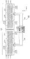
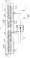
- FIG. 2 is a diagram illustrating a configuration example of the grip sensor 100 according to the present embodiment.
- the grip sensor 100 includes the sensor unit 110, the control circuit unit 120, and the harness 130 as described above.
- the sensor unit 110 includes a first sensor unit 110 a and a second sensor unit 110 b each including a base material 111 and a sensor wire 112.
- the first sensor unit 110a and the second sensor unit 110b are formed in line symmetry with a straight line along the Y-axis direction (refer to the definition of the X-axis and Y-axis below) as the symmetry axis. Have substantially the same configuration.
- the base material 111 is made of, for example, a nonwoven fabric and is formed in a long shape, and holds the sensor wire 112. This base material 111 is attached to the rim 210 of the steering wheel 200.
- the longitudinal direction of the base material 111 is referred to as an X-axis direction, and a direction perpendicular to the X-axis direction in a plane parallel to the base material 111 is referred to as a Y-axis direction.
- one end side (lower end side in FIG. 2) of the base material 111 in the Y-axis direction is referred to as a negative side
- the other end side (upper end side in FIG. 2) is referred to as a positive side.
- one end side (left end side in FIG. 2) of the base material 111 in the X-axis direction is referred to as a negative side
- the other end side (right end side in FIG. 2) is referred to as a positive side.
- the sensor wire 112 is a metal wire (for example, a copper wire), and is sewn to the surface of the base material 111 with a thread (not shown) so that a zigzag pattern is formed.
- a sensor end a (first end) that is one end of the sensor wire 112 and a power supply end b that is the other end (second end) of the sensor wire 112 are connected to the control circuit unit 120 via the harness 130. Has been.
- the sensor wire 112 is formed on the base material 111.
- a sensor line 112 includes a first line portion 112a on the sensor end a side and a second line portion 112b on the power supply end b side.
- the first line portion 112a and the second line portion 112b are respectively formed on the base material 111 in a zigzag shape.
- the sensor line 112 is sewn to the surface of the base material 111 with a thread (not shown), but may be fixed to the base material 111 by thermocompression bonding or the like. Further, the sensor line 112 may have a planar structure made of a conductor or a resistor. Details of the shape and arrangement of the sensor line 112 composed of the first line part 112a and the second line part 112b will be described later.
- the control circuit unit 120 includes a sensor circuit 122 that is electrically connected to a sensor end a that is one end of the sensor line 112, and a power supply unit 121 that is electrically connected to a power supply end b that is the other end of the sensor line 112. Is provided. That is, the sensor circuit 122 is connected to the sensor end a of the sensor line 112 of the first sensor unit 110a and the sensor end a of the sensor line 112 of the second sensor unit 110b.
- the power supply unit 121 is connected to the power supply end b of the sensor line 112 of the first sensor unit 110a and the power supply end b of the sensor line 112 of the second sensor unit 110b.
- the power supply unit 121 heats the sensor wire 112 by causing a current to flow through the sensor wire 112 in each of the first sensor unit 110a and the second sensor unit 110b. Thereby, the rim 210 of the steering wheel 200 can be warmed.
- the sensor end a is connected to the ground via an inductor, for example, so that a current flows from the power supply unit 121 to the sensor line 112.
- the sensor circuit 122 causes an alternating current to flow through the sensor line 112 via the sensor end a in each of the first sensor unit 110a and the second sensor unit 110b.
- the sensor circuit 122 detects a change in capacitance in the sensor line 112 based on the current value of the current flowing through the sensor line 112.
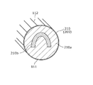
- FIG. 3 is a view showing an example of a cross section parallel to the rotation axis of the steering wheel of the rim 210 to which the sensor unit 110 is attached.
- the rim 210 includes a metal core 210b that is a metal annular core, and a resin layer 210a made of urethane resin or the like that covers the metal core 210b.
- the base material 111 on which the sensor wire 112 is sewn is wound around the resin layer 210a so that the surface opposite to the sensor wire 112 faces toward the resin layer 210a.
- the surface on the sensor wire 112 side of the base material 111 wound in this way is covered with a surface layer made of leather, wood, resin, or the like.
- the base material 111 to which the sensor wire 112 was sewn is arrange
- the substrate 111 is wound around the resin layer 210a so that the surface opposite to the sensor wire 112 faces the resin layer 210a side, but the surface of the sensor wire 112 of the substrate 111 is It may be wound around the resin layer 210a so as to face the resin layer 210a side.
- the sensor wire 112 arranged on the rim 210 forms a capacitance with the cored bar 210b.
- a capacitance is also formed between the sensor wire 112 and the hand. Therefore, the sensor circuit 122 of the control circuit unit 120 can detect gripping of the rim 210 by the hand according to the absolute value or the change amount of the electrostatic capacitance.
- the second line portion 112b is arranged in the outer periphery corresponding region 111A in the base material 111, and the first line portion 112a is connected to the front corresponding region 111B in the base material 111. It is arranged in the back corresponding area 111C.
- the outer periphery corresponding region 111 ⁇ / b> A is, for example, a region at the approximate center in the Y-axis direction of the base material 111 and extending from the negative-side end to the positive-side end of the base material 111 in the X-axis direction.
- the front corresponding region 111B is, for example, a region on the positive side of the base material 111 in the Y-axis direction and extending from the negative side end of the base material 111 to the positive side end.
- the back surface corresponding region 111C is, for example, a region on the negative side of the base material 111 in the Y-axis direction and extending from the negative side end of the base material 111 to the positive side end.
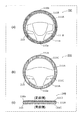
- FIG. 4 is a view showing a state in which the above-described sensor unit 110 is attached to the rim 210 of the steering wheel 200.
- 4A is a front view of the steering wheel 200
- FIG. 4B is a rear view of the steering wheel 200
- FIG. 4C is a side view of the steering wheel 200. (Bottom view).
- the first sensor unit 110a is attached to the lower half region of the rim 210
- the second sensor unit 110b is mounted to the upper half region of the rim 210. It is attached.
- the lower half region of the rim 210 is a half region on the vertically lower side of the rim 210 in a neutral state in which the steering angle of the steering wheel 200 is 0 degrees, that is, in a state in which the vehicle 1 heads in the straight traveling direction.
- the upper half area of the rim 210 is a half area on the vertical upper side of the rim 210 when the steering angle of the steering wheel 200 is 0 degree.
- the base materials 111 of the first sensor part 110a and the second sensor part 110b are arranged along the circumferential direction of the cross section of the rim 210.
- the front corresponding region 111 ⁇ / b> B of the base material 111 is disposed in front of the rim 210 as shown in FIGS. 4A and 4C.
- the back surface corresponding region 111C of the base material 111 is disposed on the back surface of the rim 210 as shown in FIGS. 4B and 4C.
- the rear surface of the rim 210 is a surface on the steering shaft side in the rotational axis direction of the steering wheel 200 (positioned in a direction close to the steering shaft), and the front surface of the rim 210 is the rotational axis of the steering wheel 200. It is a surface in the direction opposite to the steering shaft (located in the direction opposite to the back surface; first direction). Then, the outer periphery corresponding region 111A of the base material 111 is disposed on the outer peripheral surface of the rim 210 as shown in FIGS.
- the outer peripheral surface of the rim 210 is the outermost surface in the direction from the rotation center of the steering wheel 200 toward the rim 210 side.
- the harness 130 is located at a position shifted from the center in the X-axis direction on the base material 111 of each of the first sensor unit 110a and the second sensor unit 110b. b. Therefore, as shown in FIG. 4A, the first sensor unit 110a is arranged in the lower half of the rim 210, so that the harness 130 passes through the lower spoke 202 of the steering wheel 200 and the control circuit unit 120. Connected. On the other hand, the second sensor unit 110 b is arranged in the upper half of the rim 210. Therefore, the harness 130 is connected to the control circuit unit 120 through, for example, the vicinity of the cored bar 210 b and the left or right spoke 202 of the steering wheel 200.
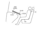
- FIG. 5 is a diagram for explaining the positional relationship between the rim 210 of the steering wheel 200 and the driver.
- the steering wheel 200 is attached to the vehicle 1 so that the front of the rim 210 faces the chest of the driver D. Therefore, 111 A of outer periphery corresponding
- the outer periphery corresponding region 111 ⁇ / b> A is attached to a leg facing portion that is a portion of the rim 210 and is a portion facing the knee or thigh of the driver who operates the steering wheel 200.
- the front corresponding region 111B in the base material 111 is directed to the chest side of the driver D, and the back corresponding region 111C in the base material 111 is directed to the side opposite to the driver's D chest.
- the front corresponding region 111 ⁇ / b> B and the back corresponding region 111 ⁇ / b> C are attached to a non-opposing portion that is a portion other than the leg facing portion in the rim 210.
- the outer periphery-corresponding region 111A is located in a seat facing part closer to the seating surface 114 than the back-corresponding region 111C and the front-corresponding region 111B.
- a second line portion 112b of the sensor wires 112 is formed in the outer periphery corresponding region 111A.
- the first line portion 112a of the sensor lines 112 is formed in the front corresponding area 111B and the rear corresponding area 111C.
- the second line portion 112b in a state where the base material 111 is attached to the rim 210, the second line portion 112b is a part of the rim 210 and is on the knee or thigh of the driver who operates the steering wheel 200. It arrange
- the second line portion 112b is a line portion on the power supply end b side of the sensor line 112, and is farther from the sensor circuit 122 than the first line portion 112a.
- the first line portion 112a is a line portion on the sensor end a side of the sensor line 112, and is closer to the sensor circuit 122 than the second line portion 112b.
- FIG. 6 is a diagram showing the relationship between the position on the sensor line 112 and the detection sensitivity of gripping at that position. Note that the horizontal axis of the graph shown in FIG. 6 indicates the position on the sensor line 112. This position is expressed as a distance from the power supply end b to the position along the sensor line 112. That is, this position is represented as a distance in the electrical connection path from the power supply end b or the power supply unit 121.
- the second line portion 112b formed in the outer periphery corresponding region 111A in the present embodiment is closer to the power supply end b than the first line portion 112a and away from the sensor circuit 122.
- the sensitivity at the line portion 112b is lower than that at the first line portion 112a.
- the second line portion 112b having low grip detection sensitivity is formed on the knee or thigh. It approaches the outer periphery corresponding region 111A. As a result, it is possible to suppress erroneous detection of the grip of the driver due to the approach to the rim 210 of the driver's knee or thigh.
- the grip sensor 100 is electrically connected to the base material 111 attached to the rim 210 of the steering wheel 200, the sensor wire 112 formed on the base material 111, and the sensor end a of the sensor wire 112. And a sensor circuit 122 that is connected to the sensor.
- the sensor line 112 includes a first line portion 112a on the sensor end a side and a second line portion 112b on the power supply end b side.
- the second line portion 112b is a portion of the rim 210 that is a portion facing the knee or thigh of the driver who operates the steering wheel 200. Placed in.
- first line portion 112 a is disposed in a non-opposing portion that is a portion other than the leg-facing portion in the rim 210. More specifically, the above-described leg facing portion is the outermost outer peripheral surface of the rim 210 in the direction from the rotation center of the steering wheel 200 toward the rim side, and the non-facing portion is the front surface of the rim 210. Including the back.
- the second line portion 112b that is far from the sensor circuit 122 in terms of the electrical connection path is disposed on the leg facing portion (that is, the outer peripheral surface) of the rim 210 of the steering wheel 200. Therefore, the detection sensitivity of the grip at the leg facing portion can be made lower than the detection sensitivity at the non-opposing portion (that is, the front surface and the back surface) of the rim 210. As a result, it can be prevented that the driver's knee or thigh approaches the leg-facing portion of the rim 210 and erroneously detects that the driver grips the steering wheel 200.
- the wiring density of the sensor lines 112 arranged in each of the outer periphery corresponding region 111A, the front corresponding region 111B, and the rear corresponding region 111C is the same, but may be different.
- This wiring density is a ratio of the areas of the sensor lines 112 arranged per unit area of the base material 111.
- the wiring density of the sensor lines 112 in the outer periphery corresponding region 111A is lower than the wiring densities of the front corresponding region 111B and the back corresponding region 111C.
- FIG. 7 is a diagram illustrating an example of the first sensor unit 110a or the second sensor unit 110b according to the present modification.
- the wiring density of the sensor lines 112 in the outer periphery corresponding region 111A is lower than the wiring density of the front corresponding region 111B and the rear corresponding region 111C.
- the pattern of the sensor line 112 is rough in the outer periphery corresponding region 111A, and conversely, it is dense in the front corresponding region 111B and the rear corresponding region 111C.
- the distance (pitch) between lines included in the sensor line 112 is long in the outer periphery corresponding region 111A and short in the front corresponding region 111B and the rear corresponding region 111C.
- the wiring density of the sensor lines 112 in the outer peripheral corresponding region 111A is low, the sensitivity in the outer peripheral corresponding region 111A can be further suppressed to be lower than the sensitivity in the front corresponding region 111B and the rear corresponding region 111C. As a result, it is possible to further suppress erroneous detection of the grip of the driver due to the proximity of the driver's knees or thighs.
- the outer periphery corresponding region 111A in the base material 111 is disposed in the leg facing portion in the rim 210, but the back surface corresponding region 111C may be disposed in the leg facing portion.
- the leg facing portion is the back surface of the rim 210
- the non-facing portion includes the front surface and the outer peripheral surface of the rim 210.
- the outer peripheral surface of the rim 210 is the outermost surface in the direction from the rotation center of the steering wheel 200 toward the rim 210 side.
- FIG. 8 is a view for explaining the positional relationship between the rim 210 of the steering wheel 200 and the driver according to this modification.
- the steering wheel 200 is attached to the vehicle 1 so that the front surface of the rim 210 is directed upward in the vertical direction as compared with the case where the vehicle 1 is a passenger car. Therefore, in this case, not the outer periphery corresponding region 111A but the back surface corresponding region 111C in the base material 111 faces the knee or thigh of the driver D.
- the outer periphery corresponding region 111A in the base material 111 is directed to the abdomen side of the driver D, and the front corresponding region 111B in the base material 111 is directed upward in the vertical direction.
- the back surface corresponding region 111C is located in a seat facing portion closer to the seat surface 114 than the outer periphery corresponding region 111A and the front surface corresponding region 111B.
- the grip sensor 100 when the vehicle 1 is a large vehicle, the driver's knee or thigh approaches the rear corresponding region 111C. Therefore, in the grip sensor 100 according to this modification, the second line portion 112b of the sensor wire 112 is formed in the back surface corresponding region 111C, and the sensor wire 112 is formed in the outer periphery corresponding region 111A and the front surface corresponding region 111B. Of these, the first line portion 112a is formed.
- the second line portion 112b is a line portion on the power supply end b side of the sensor line 112, and is farther from the sensor circuit 122 than the first line portion 112a. Yes. That is, as shown in FIG. 6, the second line portion 112b is close to the power supply end b and away from the sensor circuit 122, and therefore the sensitivity of the second line portion 112b is lower than that of the first line portion 112a. . In the present modification, the second line portion 112b is disposed in the back surface corresponding area 111C.
- the second line portion 112b having a low grip detection sensitivity is formed in the rear corresponding region 111C where the knee or thigh of the driver D approaches. Yes.
- control circuit unit 120 of the grip sensor 100 includes the power supply unit 121, but the power supply unit 121 may not be included.
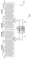
- FIG. 9 is a diagram illustrating a configuration example of a grip sensor according to this modification.
- the grip sensor 100a includes a control circuit unit 120a instead of the control circuit unit 120.
- the control circuit unit 120 a does not include the power supply unit 121. Therefore, the end c of the sensor wire 112 opposite to the sensor end a is open without being connected to the power supply unit 121.
- the grip sensor 100a does not have a function as a heater that heats the sensor wire 112 and warms the rim 210 of the steering wheel 200.
- the same effects as those of the above-described embodiment can be obtained.
- the sensitivity of the second line portion 112b is lowered by disposing the second line portion 112b far from the sensor circuit 122 in the electrical connection path in the outer periphery corresponding region 111A.
- the second line portion 112b far from the sensor circuit 122 in the electrical connection path is disposed over the outer periphery in the cross section of the rim 210 at the leg facing portion when the steering wheel 200 is in the neutral position. .
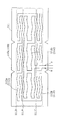
- FIG. 10 is a diagram illustrating an example of the first sensor unit 110a or the second sensor unit 110b according to the present modification.
- a second line portion 112b is formed along the Y-axis direction.
- a second line portion 112b is formed in the Y axis direction in a region (knee-facing portion) that is approximately 1/3 from the negative end of the base material 111 in the X axis direction. ing.
- the 1st line part 112a is formed in the other area
- the first line portion 112a and the second line portion 112b have substantially the same wiring density.
- the first sensor unit 110 a and the second sensor unit 110 b have the rim 210 so that the portion of the base material 111 on which the second line portion 112 b is formed is positioned vertically below the rim 210. It is arranged along the circumferential direction of the cross section. Therefore, the second line portion 112b is arranged over the outer periphery in the cross section of the rim 210 at the leg facing portion when the steering wheel 200 is in the neutral position. Due to such a configuration, the first sensor unit 110a and the second sensor unit 110b are arranged on the right half and the left half of the steering wheel 200, respectively.
- the leg-facing portion when the steering wheel 200 is in the neutral position extends over the outer periphery in the cross section of the rim 210 of that portion.
- the second line portion 112b that is far from the sensor circuit 122 in the electrical connection path and has low detection sensitivity is located. Therefore, even if the knee or thigh of the driver D approaches the knee facing portion of the steering wheel 200, the detection sensitivity of the second line portion 112b arranged in the knee facing portion is low, so that the driver D is erroneously gripped. It can suppress detecting.
- the control circuit unit 120 determines that the vehicle is steering from the output of the steering angle sensor provided in the steering wheel 200. If detected, the change in the capacitance of the first line portion 112a may be ignored or invalidated.
- the sensor wire 112 is formed so as to mainly extend in the X-axis direction of the base material 111, but is not limited to this configuration. 112 may be formed so as to extend mainly in the Y-axis direction of the substrate 111.
- the sensor wire 112 is made of a metal wire, but the sensor wire 112 may be made of a metal foil or a conductive sheet having a substantially constant width. Moreover, the sensor wire 112 should just be formed with the raw material which has electroconductivity, and the raw material is not limited to a metal.
- the first line portion 112a and the second line portion 112b of the sensor wire 112 are each formed in a zigzag shape. You may form in such a shape.
- gripping by the hand of the driver is detected, but gripping by the hand of a person other than the driver may be detected.
- the front corresponding region 111B is on the positive side in the Y-axis direction of the base material 111
- the back corresponding region 111C is on the negative side of the base material 111 in the Y-axis direction.
- the front corresponding region 111 ⁇ / b> B may be on the negative side of the base 111 in the Y-axis direction
- the back corresponding region 111 ⁇ / b> C may be on the positive side of the base 111 in the Y-axis direction.
- the front corresponding area 111 ⁇ / b> B is disposed on the front face of the rim 210
- the rear corresponding area 111 ⁇ / b> C is disposed on the rear face of the rim 210.
- a part on the sensor end a side of the first line portion 112a is formed, and the back surface on the positive side in the Y-axis direction
- a portion on the power supply end b side of the first line portion 112a may be formed.
- the sensor unit 110 is composed of two separate units, the first sensor unit 110a and the second sensor unit 110b, but may be configured integrally. There may be more than two separate units.
- the 1st sensor part 110a and the 2nd sensor part 110b have the substantially same structure, you may have a mutually different structure.
- the second sensor unit 110b attached to the upper half region of the rim 210 is unlikely to be approached by the driver's knee or thigh, so the second sensor unit 110b has the configuration shown in FIG. You may have a different structure. That is, in the second sensor unit 110b, the second line portion 112b on the power supply end b side may not be disposed in the outer periphery corresponding region 111A of the base material 111.
- the harness 130 and the control circuit part 120 are embed
- the grip sensor of the present invention has an effect of suppressing the occurrence of erroneous detection, and can be applied to, for example, a steering wheel of a vehicle.
Landscapes
- Engineering & Computer Science (AREA)
- Transportation (AREA)
- Mechanical Engineering (AREA)
- Chemical & Material Sciences (AREA)
- Combustion & Propulsion (AREA)
- Physics & Mathematics (AREA)
- Automation & Control Theory (AREA)
- General Physics & Mathematics (AREA)
- Remote Sensing (AREA)
- Life Sciences & Earth Sciences (AREA)
- Human Computer Interaction (AREA)
- Electromagnetism (AREA)
- Environmental & Geological Engineering (AREA)
- Geology (AREA)
- General Life Sciences & Earth Sciences (AREA)
- Geophysics (AREA)
- Steering Controls (AREA)
- Measurement Of Length, Angles, Or The Like Using Electric Or Magnetic Means (AREA)
- Geophysics And Detection Of Objects (AREA)
Priority Applications (3)
| Application Number | Priority Date | Filing Date | Title |
|---|---|---|---|
| DE112018000601.8T DE112018000601B4 (de) | 2017-03-13 | 2018-02-22 | Griffsensor, Lenkrad und Fahrzeug |
| CN201880017365.1A CN110431450B (zh) | 2017-03-13 | 2018-02-22 | 握持传感器、方向盘以及车辆 |
| US16/559,659 US11242069B2 (en) | 2017-03-13 | 2019-09-04 | Grip sensor, steering wheel, and vehicle |
Applications Claiming Priority (2)
| Application Number | Priority Date | Filing Date | Title |
|---|---|---|---|
| JP2017-047752 | 2017-03-13 | ||
| JP2017047752A JP6655825B2 (ja) | 2017-03-13 | 2017-03-13 | グリップセンサ、ステアリングホイールおよび車両 |
Related Child Applications (1)
| Application Number | Title | Priority Date | Filing Date |
|---|---|---|---|
| US16/559,659 Continuation US11242069B2 (en) | 2017-03-13 | 2019-09-04 | Grip sensor, steering wheel, and vehicle |
Publications (1)
| Publication Number | Publication Date |
|---|---|
| WO2018168376A1 true WO2018168376A1 (ja) | 2018-09-20 |
Family
ID=63522036
Family Applications (1)
| Application Number | Title | Priority Date | Filing Date |
|---|---|---|---|
| PCT/JP2018/006342 Ceased WO2018168376A1 (ja) | 2017-03-13 | 2018-02-22 | グリップセンサ、ステアリングホイールおよび車両 |
Country Status (5)
| Country | Link |
|---|---|
| US (1) | US11242069B2 (enExample) |
| JP (1) | JP6655825B2 (enExample) |
| CN (1) | CN110431450B (enExample) |
| DE (1) | DE112018000601B4 (enExample) |
| WO (1) | WO2018168376A1 (enExample) |
Cited By (1)
| Publication number | Priority date | Publication date | Assignee | Title |
|---|---|---|---|---|
| US20220252432A1 (en) * | 2019-07-23 | 2022-08-11 | ZF Automotive Safety Germany GmbH | Steering device sensor, measurement system, operator control system, and steering device |
Families Citing this family (5)
| Publication number | Priority date | Publication date | Assignee | Title |
|---|---|---|---|---|
| USD932398S1 (en) * | 2018-08-03 | 2021-10-05 | Tesla, Inc. | Steering wheel |
| US11220284B2 (en) * | 2019-01-25 | 2022-01-11 | Panasonic Intellectual Property Management Co., Ltd. | Steering wheel heater |
| CN111301510B (zh) * | 2020-03-20 | 2021-09-28 | 北京他山科技有限公司 | 一种具备加热功能并具有检测人体接近的传感器检测系统 |
| JP2021178527A (ja) * | 2020-05-11 | 2021-11-18 | 株式会社東海理化電機製作所 | ステアリング装置のタッチセンサ |
| DE102022105486A1 (de) | 2022-03-09 | 2023-09-14 | Zf Automotive Germany Gmbh | Handerkennungsvorrichtung für eine lenkradeinrichtung sowie lenkradanordnung mit der handerkennungsvorrichtung |
Citations (2)
| Publication number | Priority date | Publication date | Assignee | Title |
|---|---|---|---|---|
| JP2015229417A (ja) * | 2014-06-05 | 2015-12-21 | パナソニックIpマネジメント株式会社 | 操舵装置及び運輸装置 |
| WO2016013180A1 (ja) * | 2014-07-23 | 2016-01-28 | パナソニックIpマネジメント株式会社 | ヒータ装置、ステアリングホイール、および運輸装置 |
Family Cites Families (18)
| Publication number | Priority date | Publication date | Assignee | Title |
|---|---|---|---|---|
| DE10121693C2 (de) * | 2001-05-04 | 2003-04-30 | Bosch Gmbh Robert | Verfahren und Vorrichtung zum Detektieren des Kontakts von Händen mit dem Lenkrad |
| DE20309603U1 (de) | 2003-06-18 | 2003-09-25 | TAKATA-PETRI AG, 63743 Aschaffenburg | Lenkeinrichtung für ein Kraftfahrzeug |
| DE20309877U1 (de) * | 2003-06-26 | 2003-10-30 | TRW Automotive Safety Systems GmbH, 63743 Aschaffenburg | Fahrzeugsicherheitssystem |
| DE102004041320B3 (de) * | 2004-08-26 | 2005-12-15 | Florimond Neugebauer | Lenkrad für Kraftfahrzeuge |
| JP5125111B2 (ja) | 2006-03-30 | 2013-01-23 | パナソニック株式会社 | ステアリングホイール用面状発熱体 |
| US9024741B2 (en) * | 2009-11-13 | 2015-05-05 | William Bennett | Steering wheel cover driver safety system |
| JP5441655B2 (ja) | 2009-12-10 | 2014-03-12 | 株式会社クラベ | ステアリングホイール用ヒータ装置 |
| CN202130479U (zh) * | 2011-07-28 | 2012-02-01 | 孙焕 | 防瞌睡方向盘 |
| CN202662130U (zh) * | 2012-07-25 | 2013-01-09 | 徐冉 | 改良型防瞌睡方向盘套 |
| CN105143015B (zh) * | 2013-02-13 | 2018-06-29 | Tk控股公司 | 方向盘手检测系统 |
| JP5816827B1 (ja) * | 2014-05-14 | 2015-11-18 | パナソニックIpマネジメント株式会社 | グリップセンサ |
| JP6280649B2 (ja) | 2014-07-17 | 2018-02-14 | パナソニック株式会社 | 静電式ステアリングホイール把持検出装置 |
| CN205131340U (zh) * | 2015-11-18 | 2016-04-06 | 林山 | 智能方向盘套 |
| CN205220773U (zh) * | 2015-11-27 | 2016-05-11 | 厦门盈趣科技股份有限公司 | 一种方向盘防瞌睡电子装置及防瞌睡系统 |
| CN205344687U (zh) * | 2016-01-06 | 2016-06-29 | 北京汽车股份有限公司 | 一种方向盘抓握监测系统、汽车方向盘总成及汽车 |
| KR20170089328A (ko) * | 2016-01-26 | 2017-08-03 | 삼성전자주식회사 | 자동차 제어 시스템과 그의 운영 방법 |
| US11220284B2 (en) * | 2019-01-25 | 2022-01-11 | Panasonic Intellectual Property Management Co., Ltd. | Steering wheel heater |
| US20210061355A1 (en) * | 2019-08-28 | 2021-03-04 | Panasonic Intellectual Property Management Co., Ltd. | Measurement device |
-
2017
- 2017-03-13 JP JP2017047752A patent/JP6655825B2/ja active Active
-
2018
- 2018-02-22 DE DE112018000601.8T patent/DE112018000601B4/de active Active
- 2018-02-22 CN CN201880017365.1A patent/CN110431450B/zh active Active
- 2018-02-22 WO PCT/JP2018/006342 patent/WO2018168376A1/ja not_active Ceased
-
2019
- 2019-09-04 US US16/559,659 patent/US11242069B2/en active Active
Patent Citations (2)
| Publication number | Priority date | Publication date | Assignee | Title |
|---|---|---|---|---|
| JP2015229417A (ja) * | 2014-06-05 | 2015-12-21 | パナソニックIpマネジメント株式会社 | 操舵装置及び運輸装置 |
| WO2016013180A1 (ja) * | 2014-07-23 | 2016-01-28 | パナソニックIpマネジメント株式会社 | ヒータ装置、ステアリングホイール、および運輸装置 |
Cited By (2)
| Publication number | Priority date | Publication date | Assignee | Title |
|---|---|---|---|---|
| US20220252432A1 (en) * | 2019-07-23 | 2022-08-11 | ZF Automotive Safety Germany GmbH | Steering device sensor, measurement system, operator control system, and steering device |
| US12025475B2 (en) * | 2019-07-23 | 2024-07-02 | ZF Automotive Safety Germany GmbH | Steering device sensor, measurement system, operator control system, and steering device |
Also Published As
| Publication number | Publication date |
|---|---|
| US20190389489A1 (en) | 2019-12-26 |
| CN110431450A (zh) | 2019-11-08 |
| DE112018000601B4 (de) | 2022-10-13 |
| JP2018151261A (ja) | 2018-09-27 |
| CN110431450B (zh) | 2021-05-07 |
| US11242069B2 (en) | 2022-02-08 |
| DE112018000601T5 (de) | 2019-11-21 |
| JP6655825B2 (ja) | 2020-02-26 |
Similar Documents
| Publication | Publication Date | Title |
|---|---|---|
| WO2018168376A1 (ja) | グリップセンサ、ステアリングホイールおよび車両 | |
| JP6761963B2 (ja) | ステアリングホイール用乗員情報検出センサ | |
| JP5866654B1 (ja) | ヒータ装置、ステアリングホイール、および運輸装置 | |
| US20180354543A1 (en) | Electrostatic sensor | |
| WO2018168374A1 (ja) | グリップセンサ、ステアリングホイールおよび車両 | |
| JP7191149B2 (ja) | 車両のステアリング装置 | |
| JP5316527B2 (ja) | 静電容量式乗員検知装置 | |
| JP2018155717A (ja) | グリップセンサ、ステアリングホイールおよび車両 | |
| JP6642703B2 (ja) | ステアリングホイールの製造方法 | |
| WO2019202977A1 (ja) | 静電検出装置 | |
| KR101896078B1 (ko) | 차량 내부용 정전용량 감지 장치 및 시스템 | |
| JP2020040436A (ja) | 把持検出装置及びステアリングホイール | |
| JP2018142411A (ja) | グリップセンサ、ステアリングホイールおよび車両 | |
| JP2018067423A (ja) | グリップセンサ | |
| JP2019123472A (ja) | 車両用入力装置 | |
| JP2018154316A (ja) | グリップセンサ、ステアリングホイールおよび車両 | |
| JP2017140915A (ja) | ヒータ装置、ステアリングホイール、および運輸装置 | |
| JP6788857B2 (ja) | ステアリングヒータ | |
| JP2019220134A (ja) | 静電検出装置 | |
| JP2021178527A (ja) | ステアリング装置のタッチセンサ | |
| JP2019196072A (ja) | グリップセンサ | |
| JP6527803B2 (ja) | 把持検出装置及びセンサ | |
| JP2018072258A (ja) | グリップセンサ | |
| JP5135242B2 (ja) | 車両用乗員検出装置 | |
| JP2025165502A (ja) | センサマット構造、把持検知システム |
Legal Events
| Date | Code | Title | Description |
|---|---|---|---|
| 121 | Ep: the epo has been informed by wipo that ep was designated in this application |
Ref document number: 18768687 Country of ref document: EP Kind code of ref document: A1 |
|
| 122 | Ep: pct application non-entry in european phase |
Ref document number: 18768687 Country of ref document: EP Kind code of ref document: A1 |