WO2018168123A1 - 制御装置、プログラム、支援装置および支援方法 - Google Patents
制御装置、プログラム、支援装置および支援方法 Download PDFInfo
- Publication number
- WO2018168123A1 WO2018168123A1 PCT/JP2017/044486 JP2017044486W WO2018168123A1 WO 2018168123 A1 WO2018168123 A1 WO 2018168123A1 JP 2017044486 W JP2017044486 W JP 2017044486W WO 2018168123 A1 WO2018168123 A1 WO 2018168123A1
- Authority
- WO
- WIPO (PCT)
- Prior art keywords
- pedal
- vehicle speed
- mode
- driver
- actuator
- Prior art date
- Legal status (The legal status is an assumption and is not a legal conclusion. Google has not performed a legal analysis and makes no representation as to the accuracy of the status listed.)
- Ceased
Links
Images


Classifications
-
- B—PERFORMING OPERATIONS; TRANSPORTING
- B60—VEHICLES IN GENERAL
- B60K—ARRANGEMENT OR MOUNTING OF PROPULSION UNITS OR OF TRANSMISSIONS IN VEHICLES; ARRANGEMENT OR MOUNTING OF PLURAL DIVERSE PRIME-MOVERS IN VEHICLES; AUXILIARY DRIVES FOR VEHICLES; INSTRUMENTATION OR DASHBOARDS FOR VEHICLES; ARRANGEMENTS IN CONNECTION WITH COOLING, AIR INTAKE, GAS EXHAUST OR FUEL SUPPLY OF PROPULSION UNITS IN VEHICLES
- B60K31/00—Vehicle fittings, acting on a single sub-unit only, for automatically controlling vehicle speed, i.e. preventing speed from exceeding an arbitrarily established velocity or maintaining speed at a particular velocity, as selected by the vehicle operator
-
- B—PERFORMING OPERATIONS; TRANSPORTING
- B60—VEHICLES IN GENERAL
- B60W—CONJOINT CONTROL OF VEHICLE SUB-UNITS OF DIFFERENT TYPE OR DIFFERENT FUNCTION; CONTROL SYSTEMS SPECIALLY ADAPTED FOR HYBRID VEHICLES; ROAD VEHICLE DRIVE CONTROL SYSTEMS FOR PURPOSES NOT RELATED TO THE CONTROL OF A PARTICULAR SUB-UNIT
- B60W40/00—Estimation or calculation of non-directly measurable driving parameters for road vehicle drive control systems not related to the control of a particular sub unit, e.g. by using mathematical models
- B60W40/08—Estimation or calculation of non-directly measurable driving parameters for road vehicle drive control systems not related to the control of a particular sub unit, e.g. by using mathematical models related to drivers or passengers
-
- B—PERFORMING OPERATIONS; TRANSPORTING
- B60—VEHICLES IN GENERAL
- B60W—CONJOINT CONTROL OF VEHICLE SUB-UNITS OF DIFFERENT TYPE OR DIFFERENT FUNCTION; CONTROL SYSTEMS SPECIALLY ADAPTED FOR HYBRID VEHICLES; ROAD VEHICLE DRIVE CONTROL SYSTEMS FOR PURPOSES NOT RELATED TO THE CONTROL OF A PARTICULAR SUB-UNIT
- B60W50/00—Details of control systems for road vehicle drive control not related to the control of a particular sub-unit, e.g. process diagnostic or vehicle driver interfaces
- B60W50/08—Interaction between the driver and the control system
- B60W50/14—Means for informing the driver, warning the driver or prompting a driver intervention
-
- F—MECHANICAL ENGINEERING; LIGHTING; HEATING; WEAPONS; BLASTING
- F02—COMBUSTION ENGINES; HOT-GAS OR COMBUSTION-PRODUCT ENGINE PLANTS
- F02D—CONTROLLING COMBUSTION ENGINES
- F02D11/00—Arrangements for, or adaptations to, non-automatic engine control initiation means, e.g. operator initiated
- F02D11/06—Arrangements for, or adaptations to, non-automatic engine control initiation means, e.g. operator initiated characterised by non-mechanical control linkages, e.g. fluid control linkages or by control linkages with power drive or assistance
- F02D11/10—Arrangements for, or adaptations to, non-automatic engine control initiation means, e.g. operator initiated characterised by non-mechanical control linkages, e.g. fluid control linkages or by control linkages with power drive or assistance of the electric type
-
- G—PHYSICS
- G08—SIGNALLING
- G08G—TRAFFIC CONTROL SYSTEMS
- G08G1/00—Traffic control systems for road vehicles
- G08G1/16—Anti-collision systems
Definitions
- This invention relates to a technique for switching a vehicle operation mode between a manual operation mode and an automatic operation mode.
- the automatic driving mode is a mode in which the vehicle is driven mainly by a computer, and is distinguished from a manual driving mode in which a driver (driver) operates the vehicle depending on his / her limbs and senses.
- the automatic driving mode is expected to bring about effects such as reducing the driver's burden and reducing traffic congestion.
- the driver may have to drive with the steering wheel.
- it may be better to use the automatic operation mode on a highway, but to use the manual operation mode on a general road. Therefore, a technique for safely switching between the automatic operation mode and the manual operation mode is required.
- the operation of the driver and the behavior of the vehicle are basically separated. In other words, except for emergency response, the vehicle is not affected even if the steering wheel is turned off or the accelerator or brake is depressed. Conversely, in the manual operation mode, the driver's operation is directly transmitted to the vehicle. Since the operation feeling is remarkably different in this way, the safety depends on how smoothly the operation can be transferred from the computer to the human when the operation mode is switched.
- Japanese Patent Application Laid-Open No. 2015-182525 discloses a technique aiming at a smooth change to the speed required by the driver when switching to manual operation. However, there is no discussion about the needs from another point of view, how to smoothly take over pedal operation while maintaining speed.
- Handing over includes handing over the steering wheel, handing over the pedal, and handing over the visual, but there is a demand for technical development related to pedaling.
- the present invention has been made paying attention to the above circumstances, and an object thereof is to allow the driver to smoothly take over the pedal operation, thereby improving safety.
- the present invention takes the following measures.
- 1st aspect of this invention is the assistance apparatus which assists a driver
- the first mode is a mode in which the operation amount of the pedal for vehicle speed control is not related to the vehicle speed
- the second mode is a mode in which the operation amount is related to the vehicle speed.
- the support device includes an actuator that generates a driving force to position the pedal, a detector that detects the driver's foot on the pedal, and a control device.
- the control device controls the actuator in response to the start of switching from the first mode to the second mode, thereby setting the pedal at a depression position corresponding to the vehicle speed, and the pedal corresponding to the vehicle speed.
- the release unit is configured to release the pedal from the driving force of the actuator with a time constant set to a value that the driver can follow.
- the pedal control unit is configured to set the pedal at a depression position corresponding to the vehicle speed based on vehicle speed data obtained from a vehicle speed sensor.
- the detector is configured to be a sensor that detects a load on the pedal.
- the detector is configured to be an image sensor that analyzes video data obtained by photographing an area including a pedal and detects a footrest on the pedal.
- the pedal controller is configured to notify the driver whether the pedal is an accelerator pedal or a brake pedal when controlling the actuator.
- the depression position of the accelerator pedal corresponds to the vehicle speed by the actuator.
- position accelerator opening
- the pedal is in the depressed position corresponding to the vehicle speed from the beginning, and when the driver puts his / her foot on, the force (driving force) for positioning the pedal is released. Therefore, the driver can take over the pedal operation from the depressed position corresponding to the vehicle speed. Accordingly, the driver can take over the pedal operation at an appropriate depression position, and thus the safety related to the mode switching can be improved.
- the pedal is released from the driving force of the actuator by the release portion with a time constant set to a value that the driver can follow. Because of this configuration, the pedal operation is gradually handed over from the machine to the human foot rather than as soon as the foot is placed. At this time, the driver may be given an announcement such as "Start pedal takeover". The driver feels that the force for positioning the pedal gradually decreases, and keeps the position of the pedal following that. Thus, since the pedal operation can be taken over in a state where the balance of the force for operating the pedal is maintained, the safety related to the mode switching can be improved.
- the depression position of the pedal is set based on the vehicle speed data obtained from the vehicle speed sensor. As a result, it is possible to cope with a case where the vehicle speed changes in the switching section.
- the footrest on the pedal is detected by the sensor that detects the load on the pedal. Since it is such a structure, the footrest on a pedal can be detected by a simple means.
- the footrest on the pedal is detected by the image sensor that analyzes the video data obtained by photographing the area including the pedal. Since it is such a structure, since it is not necessary to attach a sensor to pedal itself, weight reduction of a pedal can be promoted.
- the handover process is started after the driver is notified whether the pedal to be handed over is an accelerator pedal or a brake pedal. Therefore, the driver can surely recognize the pedal to be handed over.
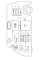
- FIG. 1 is a diagram illustrating an overall configuration of an automatic driving control system including a support device according to an embodiment of the present invention.
- FIG. 2 is an external view showing an example of the vicinity of the accelerator pedal 10 on the driver's seat side floor.
- FIG. 3 is an external view showing an example of a driver seat.
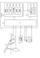
- FIG. 4 is a functional block diagram showing an example of the pedal ECU 5 shown in FIG.
- FIG. 5 is a diagram for explaining one of the concepts related to mode switching.
- FIG. 6 is a flowchart illustrating an example of a processing procedure according to the embodiment.
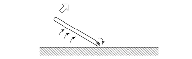
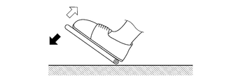
- FIG. 7A is a schematic diagram showing a change in the position of the accelerator pedal 10 during mode switching.
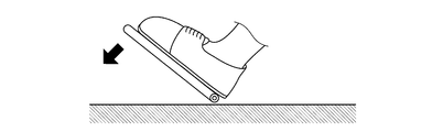
- FIG. 7B is a schematic diagram showing a change in the position of the accelerator pedal 10 during mode switching.
- FIG. 7C is a schematic diagram showing a change in the position of the accelerator pedal 10 during mode switching.
- FIG. 7D is a schematic diagram showing a change in the position of the accelerator pedal 10 during mode
- FIG. 1 is a block diagram showing an example of an automatic driving control system including a support device according to an embodiment of the present invention.
- This automatic driving control system is mounted on the vehicle 1.
- the vehicle 1 can travel in either the manual operation mode or the automatic operation mode.
- the mode switching control device 6 performs control related to the mode switching.
- the vehicle 1 includes a power unit 2 and a steering device 3 as basic equipment.
- the power unit 2 includes a power source and a transmission.
- As the power source an internal combustion engine, an electric motor, or both can be used.
- the steering device 3 is connected to the steering wheel 4.
- the automatic driving mode is a mode that realizes an operating state in which the vehicle 1 automatically travels along the road, for example.
- the automatic driving mode may include, for example, a driving state in which the vehicle 1 automatically travels toward a preset destination without driving by the driver. In the automatic driving mode, it is not always necessary to control all the behaviors of the vehicle 1.
- the automatic driving mode may include a driving state in which the driving operation of the driver is reflected in the traveling of the vehicle 1 within a preset allowable range. In this embodiment, it is assumed that the pedal operation amount for vehicle speed control is not related to the vehicle speed in the automatic operation mode.
- the driving operation support control assists the driving operation of the vehicle 1 so as to drive along the curve by assisting the steering by the driver when the vehicle 1 is traveling on the curve, for example.
- the driving operation support control includes control for assisting the driver's accelerator operation (for example, operation of the accelerator pedal) or brake operation (for example, operation of the brake pedal), manual steering (manual operation of steering), and manual speed adjustment (speed adjustment). Manual operation) or the like.
- Manual steering is to operate the traveling direction of the vehicle 1 mainly by the driver's operation of the steering wheel.
- the manual speed adjustment is to adjust the speed of the vehicle 1 mainly by the driver's accelerator operation or brake operation.
- the manual operation mode is a mode in which the vehicle 1 is driven mainly by a driver's manual driving operation, for example.
- the manual operation mode is, for example, an operation mode in which the vehicle 1 travels based only on the driving operation of the driver and an operation mode in which driving operation support control is performed to assist the driving operation of the driver while mainly driving the driving operation of the driver. And may be included.
- description will be made assuming that the pedal operation amount for vehicle speed control is related to the vehicle speed in the manual operation mode.
- Automatic control includes, for example, automatic steering (automatic steering operation) and automatic speed adjustment (automatic driving of speed).
- Automatic steering is an operating state in which the steering device is automatically controlled.
- Automatic steering includes LKA (Lane Keeping Assist).
- LKA Li Keeping Assist
- the LKA automatically controls the steering device 3 so that the vehicle 1 does not deviate from the traveling lane even when the driver does not perform the steering operation.
- the driver's steering operation may be reflected in the steering of the vehicle 1 within a range (allowable range) in which the vehicle 1 does not deviate from the travel lane even during execution of LKA.
- automatic steering is not limited to LKA.
- Automatic speed adjustment is an operating state in which the speed of the vehicle 1 is automatically controlled.
- Automatic speed adjustment includes ACC (Adaptive Cruise Control). For example, when there is no preceding vehicle ahead of the vehicle 1, the ACC performs constant speed control that causes the vehicle 1 to travel at a constant speed at a preset speed. Further, when a preceding vehicle is present in front of the vehicle 1, the ACC performs follow-up control for adjusting the vehicle speed of the vehicle 1 according to the inter-vehicle distance from the preceding vehicle.
- ACC Adaptive Cruise Control
- the vehicle 1 decelerates if there is a driver's brake operation (for example, operation of a brake pedal). Further, even if the ACC is being executed, if there is an accelerator operation (for example, an accelerator pedal operation) by the driver, a preset maximum permissible speed (for example, the maximum speed legally determined on the running road) ) Until the vehicle 1 can be accelerated. Note that not only ACC but also CC (Cruise Control) is included in the category of automatic speed adjustment.
- the mode switching control device 6 is a computer that executes control related to mode switching for switching the operation mode of the vehicle.
- the mode switching control device 6 is connected to a display unit 9 as an example of a display.
- the display unit 9 displays a map around the vehicle, various information, messages, and the like.
- the display unit 9 is, for example, a touch panel of a car navigation system, a head-up display, a display of a smartphone or a tablet terminal, and the like, and is a human machine interface between a passenger (including a driver) and the mode switching control device 6.
- a speaker (not shown) is also included in this type of human machine interface.
- the mode switching control device 6 is connected to the driver camera 7.
- the driver camera 7 is disposed at a place where the driver can be imaged, for example, on a dashboard, and images the inside of the vehicle including the driver.
- the mode switching control device 6 is connected to the GPS receiver 14.
- the GPS receiver 14 captures a plurality of GPS satellites and calculates three-dimensional position data (positioning information) of the vehicle 1 based on the positioning information transmitted from each satellite. Based on the position data of the vehicle 1 and information from the navigation system (not shown), the mode switching control device 6 determines approach of a switching section related to mode switching. When recognizing that the switching section is approaching, the mode switching control device 6 starts control related to mode switching.
- the switching section is a section of a certain length provided so that the operation mode can be switched with ease. For example, it is conceivable to set a switching section of about 100m to several kilometers before the interchange, etc., and to perform mode switching after the surroundings have been prepared for visual observation and the safety can be sufficiently secured. Yes. A period (also referred to as a switching period) required for traveling in this section is approximately 60 seconds.
- the automatic operation control system in the present embodiment includes a pedal ECU (Electronic Control Unit) 5.
- the pedal ECU 5 is a computer as a control device provided in a support device that assists the driver during mode switching.
- the pedal ECU 5 acquires sensing data from the foot camera 8, the load sensor 11, the pedal sensor 12, the gyro sensor 15, and the vehicle speed sensor 16 via a not-shown in-vehicle LAN (Local Area Network).
- the pedal ECU 5 is communicably connected to the mode switching control device 6 to exchange various data with each other.
- the pedal ECU 5 is communicably connected to an actuator 13 that generates a driving force and positions the accelerator pedal 10, and outputs a control signal for controlling the actuator 13.
- the accelerator pedal 10 is controlled by the pedal ECU 5.
- the system containing pedal ECU5, the foot camera 8 or the load sensor 11, and the actuator 13 as an assistance apparatus which assists a driver
- FIG. 2 is an external view showing an example of the vicinity of the accelerator pedal 10 on the driver's seat side floor.
- the vehicle 1 travels without permission even when the accelerator pedal 10 is released.
- the foot camera 8 is attached to a position that does not interfere with the driver's side floor.
- the foot camera 8 captures a floor portion including the accelerator pedal 10 and analyzes the obtained video data to detect the footrest on the accelerator pedal 10. The result of this detection is notified to the pedal ECU 5.
- FIG. 3 is an external view showing an example of a driver seat.
- the load sensor 11 is attached to, for example, a portion of the seat where the right thigh is placed, and can detect the presence or absence of a passenger by tracing the load or trace the movement of the right foot.
- the detected pressure also changes depending on whether the foot is on the accelerator pedal 10 or not. That is, the load sensor 11 detects the load on the accelerator pedal 10 and notifies the pedal ECU 5 of the presence or absence of footrest based on the result. If both the foot camera 8 and the load sensor 11 are used, they can complement each other, and only one of them can be used as long as sufficient sensing accuracy can be obtained.
- FIG. 4 is a functional block diagram illustrating an example of the pedal ECU 5.
- the pedal ECU 5 includes an I / O (input / output interface) 51, a control unit 52, and a memory 53.
- the memory 53 is a semiconductor memory such as RAM (Random Access Memory), ROM (Read Only Memory), flash memory, SDRAM (Synchronous Dynamic RAM), EPROM (Erasable Programmable ROM), EPROM (Electrically Erasable Programmable ROM), etc. It may be a non-volatile memory or a storage medium such as an SSD (Solid State Drive) or HDD (Hard Disk Drive). Alternatively, it may be a storage area provided inside a one-chip microcomputer such as an FPGA (Field Programmable Gate Array) or a PIC (Peripheral Interface Controller).
- FPGA Field Programmable Gate Array
- PIC Peripheral Interface Controller
- the I / O 51 acquires operation amount data of the accelerator pedal 10 from the pedal sensor 12.
- the operation amount data is data indicating the position of the accelerator pedal 10 or the accelerator opening (depression amount), and is an amount that can be measured in an analog or digital manner by a positioning meter such as a potentiometer.
- the acquired operation amount data is stored in the memory 53 as one of the sensing data 53b. Sensing data 53b including this operation amount data is exchanged with the mode switching control device 6 through the I / O 51 as appropriate.
- the I / O 51 acquires detection data indicating whether or not the accelerator pedal 10 is placed on the foot from the foot camera 8. This detection data is stored in the memory 53 as one of the sensing data 53b. Note that only the video data may be acquired and the data analysis may be executed on the pedal ECU 5 side.
- the I / O 51 acquires pressure data from the load sensor 11 and stores it in the memory 53 as one of the sensing data 53b.
- the pedal ECU 5 analyzes the pressure data and detects whether or not the accelerator pedal 10 is placed on the foot. Of course, the load sensor 11 may perform this analysis.
- the I / O 51 acquires various data (for example, rotation speed data, output data, torque data, fuel injection amount data, etc.) from the power unit 2 of the vehicle 1. These data are stored in the memory 53 as sensing data 53b.
- the I / O 51 acquires the attitude data of the vehicle 1 from the gyro sensor 15 and stores it in the memory 53 as one of the sensing data 53b. Further, the I / O 51 acquires the speed data of the vehicle 1 from the vehicle speed sensor 16 and stores it in the memory 53 as one of the sensing data 53b.
- the control unit 52 has a CPU (Central Processing Unit) that constitutes a computer.
- the control unit 52 includes an acquisition unit 52a, a calculation unit 52b, a pedal control unit 52c, a detection unit 52d, and a release unit 52f as functions necessary for carrying out this embodiment. These functions are realized by the CPU reading the support program 53a written in the memory 53 into a register and executing it.
- CPU Central Processing Unit
- the acquisition unit 52a acquires necessary sensing data 53b including speed data from the memory 53.
- the calculation unit 52b calculates the position (or operation amount) of the accelerator pedal 10 corresponding to the speed data.
- the pedal controller 52c controls the actuator 13 in the initial phase of the switching period from the automatic operation mode to the manual operation mode, sets the accelerator opening to the vehicle speed corresponding position, and temporarily holds this state. That is, the pedal controller 52 c generates a control signal for setting the depression position of the accelerator pedal 10 to the vehicle speed corresponding position, and transmits the control signal to the actuator 13 via the I / O 51. As a result, the actuator 13 generates a driving force and moves the accelerator pedal 10.
- the detecting unit 52d detects the footrest on the accelerator pedal 10 based on the detection data from the foot camera 8 and the pressure data from the load sensor 11.
- the release unit 52f releases the accelerator pedal 10 that is stepped on at a position corresponding to the vehicle speed from the driving force of the actuator 13 in the final phase of mode switching, that is, immediately before switching to the manual operation mode in the switching period.
- FIG. 5 is a diagram for explaining one of the concepts related to mode switching.
- three sections can be considered for mode switching. That is, an automatic operation section, an automatic ⁇ manual operation switching section (abbreviated as a switching section), and a manual operation section. Control regarding mode switching is sequentially executed in the three sections.
- the mode switching from the automatic operation mode to the manual operation mode will be considered.
- These sections may be set in advance, for example, before the exit from the highway to the general road.
- the mode switching from the automatic operation mode to the manual operation mode is started to reach the switching section.
- the switching section countermeasures for mode switching to manual operation are performed. One of them is taking over the accelerator pedal. And if mode switching is completed safely before going out to a general road, a manual driving area will be started. Further, for example, if switching to the automatic operation mode is not permitted, an emergency response is executed, and for example, measures for evacuation and stop to the roadside belt are taken.
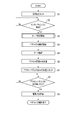
- FIG. 6 is a flowchart illustrating an example of a processing procedure according to the embodiment.
- the procedure shown in this flowchart is realized by the mode switching control device 6 and the pedal ECU 5 operating in cooperation with each other.
- the vehicle 1 traveling on the highway in the automatic driving mode approaches an interchange near the destination and performs mode switching from the automatic driving mode to the manual driving mode.
- step S1 when a destination is set using a navigation system (not shown) (step S1), the mode switching control device 6 waits for an approach to an interchange on the route (step S2). It is assumed that the position of the accelerator pedal 10 is free when cruising in the automatic driving mode, and is stopped at the maximum depressed position, for example, as shown in FIG. 7A.
- step S2 when the approach to the interchange is recognized (step S2: Yes), the mode switching control device 6 starts the mode switching process (step S3) and takes over the process to the pedal ECU 5. As a result, the accelerator pedal takeover process is started (step S4).
- step S5 the pedal ECU 5 performs data analysis (step S5), and calculates the accelerator opening degree Ar corresponding to the speed data acquired by the vehicle speed sensor 16 (step S6).
- step S6 the pedal ECU 5 gives a control signal to the actuator 13, and sets the depression position of the accelerator pedal 10 to a position corresponding to the accelerator opening degree Ar calculated in step S6 (step S7).
- the accelerator pedal 10 is temporarily held in the middle speed range as shown in FIG. 7B, for example.
- the amount of operation of the accelerator pedal 10 is not transmitted to the power unit 2 at this stage. That is, in the automatic operation mode, the information transmission path between the operation amount of the accelerator pedal 10 and the power unit 2 is basically disconnected, and the accelerator opening does not affect the behavior of the vehicle. Therefore, no matter how the actuator 13 moves the accelerator pedal 10, the speed of the vehicle 1 does not change.
- the pedal ECU 5 waits for footing on the accelerator pedal 10 (step S8).
- the driver puts his / her foot on the accelerator pedal 10 as shown in FIG. 7C, the driver feels that the accelerator pedal 10 is fixed by the driving force applied to the actuator 13.
- an announcement such as “keep the position with the foot on” may be issued from a speaker or the like.
- the pedal ECU 5 gradually removes the driving force from the actuator 13 (FIG. 7D). Thereby, the accelerator pedal 10 that is stepped on at a position corresponding to the vehicle speed is released from the driving force of the actuator 13 (step S9).
- the driving force is removed with a long time constant while maintaining a period during which the driver can not be surprised (for example, about several seconds).
- the driver feels that the force for positioning the accelerator pedal 10 is gradually released, and eventually recovers the normal operation feeling.
- this state is reached, the handover of the accelerator pedal is completed.
- the actuator 13 connected to the accelerator pedal 10 is controlled, and the depression position of the accelerator pedal 10 is a position corresponding to the vehicle speed. Set to.
- the driving force of the actuator to the accelerator pedal 10 is gradually released to complete the accelerator pedal takeover process.
- the driver only needs to place his / her foot on the accelerator pedal 10 set at a position corresponding to the vehicle speed and maintain the accelerator position. Therefore, when the driver takes over the pedal, the driver can easily shift from the speed adjustment by the machine to the speed adjustment by the accelerator operation of the driver.
- the driver can smoothly take over the pedal operation, thereby providing a control device, a program, a support device, and a support method for improving safety.
- the present invention is not limited to the above embodiment.
- a so-called organ-type accelerator pedal is illustrated in the embodiment, it is apparent that the present invention can be applied to a mainstream suspension-type accelerator pedal in recent years. It is also clear that the present invention can be applied to a brake pedal as a pedal for controlling the vehicle speed.
- step S4 of FIG. 6 after the announcement “Start taking over the accelerator pedal” is displayed on the display unit 9 or output from a speaker (not shown), the pedal ECU 5 performs the next step S5 (You may move to (Data analysis). If the brake pedal is to be handed over, for example, an announcement that “brake pedal handing over will be started” may be displayed on the display unit 9 or output from a speaker (not shown). In this way, the driver can reliably recognize whether the pedal to be handed over is an accelerator pedal or a brake pedal.
- the accelerator pedal 10 may be fixed at the maximum depressed position. This is because the accelerator opening does not affect the vehicle speed during the automatic operation mode. If it does in this way, the floor space by the side of a driver's seat can be taken widely and habitability can be improved. Conversely, if the accelerator pedal 10 is fixed to the front, it can be used as a footrest and relaxed.
- the switching section for mode switching can be set to a somewhat free place.
- a switching section is set somewhere, for example, 100 m to several km ahead of the vehicle 1, and the mode is set within this section.
- Various controls related to switching and handover may be performed.
- the intention display by the driver can be indicated by an operation using a push button provided on the steering wheel 4, a soft button provided on the touch panel, or an operation of an accelerator pedal.
- a driver's voice intention display may be recognized by a computer.
- the load on the accelerator pedal 10 is detected by a load sensor attached to the seat. Instead of this, even if a small sensor such as a piezoelectric sensor is attached directly to the accelerator pedal 10, the footrest can be detected.
- the apparatus of the present invention can be realized by a computer and a program, and the program can be recorded on a recording medium or provided through a network.
- each of the above devices and their device parts can be implemented with either a hardware configuration or a combined configuration of hardware resources and software.
- the software of the combined configuration a program for causing the computer to realize the functions of each device by being installed in a computer from a network or a computer-readable recording medium in advance and executed by a processor of the computer is used.
- processor used in connection with a computer is, for example, CPU, GPU (Graphics Processing Unit), ASIC (Application Specific Integrated Circuit), SPLD (Simple Programmable Logic Device), CPLD (Complex Programmable Logic Device), Or it can be understood as a circuit such as an FPGA.
- the processor reads out and executes the program stored in the memory, thereby realizing a specific function based on the program.
- the program may be directly incorporated in the processor circuit.
- the processor realizes its function by reading and executing a program incorporated in the circuit.
- the vehicle type, the function of the automatic driving control device, the function and processing procedure and processing content of the mode switching control device can be variously modified and implemented without departing from the gist of the present invention.
- the present invention is not limited to the above-described embodiment as it is, and can be embodied by modifying the constituent elements without departing from the scope of the invention in the implementation stage.
- various inventions can be formed by appropriately combining a plurality of constituent elements disclosed in the embodiment. For example, some components may be deleted from all the components shown in the embodiment. Furthermore, you may combine suitably the component covering different embodiment.
- a control device provided in the apparatus, A processor, The processor is In response to the start of switching from the first mode to the second mode, by controlling an actuator that generates a driving force and positions the pedal, the pedal is set at a depression position corresponding to the vehicle speed, In the state where the pedal is in the depressed position corresponding to the vehicle speed, when a footrest on the pedal is detected by a detector that detects the footrest of the driver on the pedal, the position corresponding to the vehicle speed is A control device configured to release the pedal in a depressed state from the driving force of the actuator.
- a device An actuator for generating a driving force to position the pedal; A detector for detecting the driver's footrest on the pedal; A processor capable of transmitting and receiving signals between the actuator and the detector, The processor is By controlling the actuator in response to the start of switching from the first mode to the second mode, the pedal is set at a depression position corresponding to the vehicle speed, When the detector detects a footrest on the pedal in a state where the pedal is in a depressed position corresponding to the vehicle speed, the pedal in a state where the pedal is depressed in a position corresponding to the vehicle speed is A support device configured to release from driving force.
- a computer assists the driver in switching the vehicle operation mode between the first mode in which the pedal operation amount for vehicle speed control is not related to the vehicle speed and the second mode in which the operation amount is related to the vehicle speed.
- a support method for In response to the start of switching from the first mode to the second mode, an actuator that generates driving force and positions the pedal is controlled using at least one hardware processor, and the pedal is adapted to the vehicle speed.
- the process of setting the stepping position to In the state where the pedal is in the depressed position corresponding to the vehicle speed, when the detector detects a footrest on the pedal, the pedal in the state where the pedal is depressed in the position corresponding to the vehicle speed is at least 1 And releasing the driving force of the actuator using two hardware processors.
Landscapes
- Engineering & Computer Science (AREA)
- Mechanical Engineering (AREA)
- Transportation (AREA)
- Automation & Control Theory (AREA)
- Physics & Mathematics (AREA)
- Chemical & Material Sciences (AREA)
- Combustion & Propulsion (AREA)
- General Engineering & Computer Science (AREA)
- General Physics & Mathematics (AREA)
- Mathematical Physics (AREA)
- Human Computer Interaction (AREA)
- Control Of Driving Devices And Active Controlling Of Vehicle (AREA)
- Traffic Control Systems (AREA)
- Controls For Constant Speed Travelling (AREA)
Applications Claiming Priority (2)
| Application Number | Priority Date | Filing Date | Title |
|---|---|---|---|
| JP2017048070A JP2018149932A (ja) | 2017-03-14 | 2017-03-14 | 制御装置、プログラム、支援装置および支援方法 |
| JP2017-048070 | 2017-03-14 |
Publications (1)
| Publication Number | Publication Date |
|---|---|
| WO2018168123A1 true WO2018168123A1 (ja) | 2018-09-20 |
Family
ID=63523545
Family Applications (1)
| Application Number | Title | Priority Date | Filing Date |
|---|---|---|---|
| PCT/JP2017/044486 Ceased WO2018168123A1 (ja) | 2017-03-14 | 2017-12-12 | 制御装置、プログラム、支援装置および支援方法 |
Country Status (2)
| Country | Link |
|---|---|
| JP (1) | JP2018149932A (enExample) |
| WO (1) | WO2018168123A1 (enExample) |
Cited By (2)
| Publication number | Priority date | Publication date | Assignee | Title |
|---|---|---|---|---|
| JP2019093924A (ja) * | 2017-11-23 | 2019-06-20 | 本田技研工業株式会社 | 車両の制御装置 |
| CN114212090A (zh) * | 2021-12-15 | 2022-03-22 | 上海集度汽车有限公司 | 车辆驾驶模式切换方法、装置及车辆 |
Families Citing this family (3)
| Publication number | Priority date | Publication date | Assignee | Title |
|---|---|---|---|---|
| CN110053626B (zh) * | 2019-05-10 | 2021-07-06 | 深圳市元征科技股份有限公司 | 一种车辆控制方法及相关装置 |
| JP7639615B2 (ja) * | 2021-08-25 | 2025-03-05 | 株式会社デンソー | アクセルペダルシステム |
| JP2023175208A (ja) * | 2022-05-30 | 2023-12-12 | 株式会社Soken | アクセルペダルシステム |
Citations (4)
| Publication number | Priority date | Publication date | Assignee | Title |
|---|---|---|---|---|
| JP2005082041A (ja) * | 2003-09-09 | 2005-03-31 | Toyota Motor Corp | 車両用自動ブレーキ装置 |
| JP2007199939A (ja) * | 2006-01-25 | 2007-08-09 | Equos Research Co Ltd | 自動運転制御装置 |
| JP2016172477A (ja) * | 2015-03-17 | 2016-09-29 | トヨタ自動車株式会社 | 駆動または制動が自動制御される車輌のペダル装置 |
| WO2016199379A1 (ja) * | 2015-06-11 | 2016-12-15 | パナソニックIpマネジメント株式会社 | 車両制御装置、車両制御方法および車両制御プログラム |
-
2017
- 2017-03-14 JP JP2017048070A patent/JP2018149932A/ja active Pending
- 2017-12-12 WO PCT/JP2017/044486 patent/WO2018168123A1/ja not_active Ceased
Patent Citations (4)
| Publication number | Priority date | Publication date | Assignee | Title |
|---|---|---|---|---|
| JP2005082041A (ja) * | 2003-09-09 | 2005-03-31 | Toyota Motor Corp | 車両用自動ブレーキ装置 |
| JP2007199939A (ja) * | 2006-01-25 | 2007-08-09 | Equos Research Co Ltd | 自動運転制御装置 |
| JP2016172477A (ja) * | 2015-03-17 | 2016-09-29 | トヨタ自動車株式会社 | 駆動または制動が自動制御される車輌のペダル装置 |
| WO2016199379A1 (ja) * | 2015-06-11 | 2016-12-15 | パナソニックIpマネジメント株式会社 | 車両制御装置、車両制御方法および車両制御プログラム |
Cited By (2)
| Publication number | Priority date | Publication date | Assignee | Title |
|---|---|---|---|---|
| JP2019093924A (ja) * | 2017-11-23 | 2019-06-20 | 本田技研工業株式会社 | 車両の制御装置 |
| CN114212090A (zh) * | 2021-12-15 | 2022-03-22 | 上海集度汽车有限公司 | 车辆驾驶模式切换方法、装置及车辆 |
Also Published As
| Publication number | Publication date |
|---|---|
| JP2018149932A (ja) | 2018-09-27 |
Similar Documents
| Publication | Publication Date | Title |
|---|---|---|
| CN114655237B (zh) | 驾驶转换控制装置以及驾驶转换控制方法 | |
| US11001271B2 (en) | Drive assistance device | |
| CN111469848B (zh) | 车辆控制装置 | |
| US10131277B2 (en) | Surroundings monitoring apparatus | |
| US11273822B2 (en) | Parking assist apparatus | |
| WO2018168123A1 (ja) | 制御装置、プログラム、支援装置および支援方法 | |
| US20190210586A1 (en) | Drive mode switch controller, method, and program | |
| JP6651925B2 (ja) | 運転支援装置、運転支援方法 | |
| US20180329415A1 (en) | Driver monitoring apparatus and driver monitoring method | |
| EP3805065B1 (en) | State determination device, driving support device, state determination method, and driving support method | |
| WO2018163473A1 (ja) | 支援装置、支援方法およびプログラム | |
| CN108860155A (zh) | 驾驶辅助装置以及驾驶辅助方法 | |
| EP3133454A1 (en) | Method and apparatus for controlling a vehicle having automated driving control capabilities | |
| WO2019026469A1 (ja) | 車両制御装置、車両制御方法、車両制御プログラム | |
| JP2021026558A (ja) | 運転引継制御装置 | |
| JP6388044B1 (ja) | 制御装置、プログラム、支援装置および支援方法 | |
| JP7519397B2 (ja) | 制御装置、制御装置の動作方法、プログラム及び記憶媒体 | |
| CN111391827B (zh) | 车辆控制装置 | |
| WO2018168124A1 (ja) | 制御装置、プログラム、支援装置および支援方法 | |
| WO2022249837A1 (ja) | 機能制御装置、機能制御プログラム、自動運転制御装置、及び自動運転制御プログラム | |
| WO2023175928A1 (ja) | 運転支援方法及び運転支援装置 | |
| JP7683593B2 (ja) | 車両用表示制御装置及び車両用表示制御方法 | |
| CN118804859B (zh) | 驾驶辅助方法及驾驶辅助装置 | |
| CN113479205B (zh) | 移动体控制装置、移动体以及移动体控制方法 | |
| CN116749987A (zh) | 车辆控制装置 |
Legal Events
| Date | Code | Title | Description |
|---|---|---|---|
| 121 | Ep: the epo has been informed by wipo that ep was designated in this application |
Ref document number: 17901032 Country of ref document: EP Kind code of ref document: A1 |
|
| NENP | Non-entry into the national phase |
Ref country code: DE |
|
| 122 | Ep: pct application non-entry in european phase |
Ref document number: 17901032 Country of ref document: EP Kind code of ref document: A1 |