WO2018168044A1 - 回転式圧縮機および冷凍サイクル装置 - Google Patents
回転式圧縮機および冷凍サイクル装置 Download PDFInfo
- Publication number
- WO2018168044A1 WO2018168044A1 PCT/JP2017/037368 JP2017037368W WO2018168044A1 WO 2018168044 A1 WO2018168044 A1 WO 2018168044A1 JP 2017037368 W JP2017037368 W JP 2017037368W WO 2018168044 A1 WO2018168044 A1 WO 2018168044A1
- Authority
- WO
- WIPO (PCT)
- Prior art keywords
- rotary compressor
- compressed gas
- compression mechanism
- shaft
- rotor
- Prior art date
- Legal status (The legal status is an assumption and is not a legal conclusion. Google has not performed a legal analysis and makes no representation as to the accuracy of the status listed.)
- Ceased
Links
Images


Classifications
-
- F—MECHANICAL ENGINEERING; LIGHTING; HEATING; WEAPONS; BLASTING
- F04—POSITIVE - DISPLACEMENT MACHINES FOR LIQUIDS; PUMPS FOR LIQUIDS OR ELASTIC FLUIDS
- F04B—POSITIVE-DISPLACEMENT MACHINES FOR LIQUIDS; PUMPS
- F04B39/00—Component parts, details, or accessories, of pumps or pumping systems specially adapted for elastic fluids, not otherwise provided for in, or of interest apart from, groups F04B25/00 - F04B37/00
-
- F—MECHANICAL ENGINEERING; LIGHTING; HEATING; WEAPONS; BLASTING
- F04—POSITIVE - DISPLACEMENT MACHINES FOR LIQUIDS; PUMPS FOR LIQUIDS OR ELASTIC FLUIDS
- F04B—POSITIVE-DISPLACEMENT MACHINES FOR LIQUIDS; PUMPS
- F04B39/00—Component parts, details, or accessories, of pumps or pumping systems specially adapted for elastic fluids, not otherwise provided for in, or of interest apart from, groups F04B25/00 - F04B37/00
- F04B39/04—Measures to avoid lubricant contaminating the pumped fluid
-
- F—MECHANICAL ENGINEERING; LIGHTING; HEATING; WEAPONS; BLASTING
- F04—POSITIVE - DISPLACEMENT MACHINES FOR LIQUIDS; PUMPS FOR LIQUIDS OR ELASTIC FLUIDS
- F04C—ROTARY-PISTON, OR OSCILLATING-PISTON, POSITIVE-DISPLACEMENT MACHINES FOR LIQUIDS; ROTARY-PISTON, OR OSCILLATING-PISTON, POSITIVE-DISPLACEMENT PUMPS
- F04C29/00—Component parts, details or accessories of pumps or pumping installations, not provided for in groups F04C18/00 - F04C28/00
-
- F—MECHANICAL ENGINEERING; LIGHTING; HEATING; WEAPONS; BLASTING
- F04—POSITIVE - DISPLACEMENT MACHINES FOR LIQUIDS; PUMPS FOR LIQUIDS OR ELASTIC FLUIDS
- F04C—ROTARY-PISTON, OR OSCILLATING-PISTON, POSITIVE-DISPLACEMENT MACHINES FOR LIQUIDS; ROTARY-PISTON, OR OSCILLATING-PISTON, POSITIVE-DISPLACEMENT PUMPS
- F04C29/00—Component parts, details or accessories of pumps or pumping installations, not provided for in groups F04C18/00 - F04C28/00
- F04C29/02—Lubrication; Lubricant separation
-
- F—MECHANICAL ENGINEERING; LIGHTING; HEATING; WEAPONS; BLASTING
- F04—POSITIVE - DISPLACEMENT MACHINES FOR LIQUIDS; PUMPS FOR LIQUIDS OR ELASTIC FLUIDS
- F04C—ROTARY-PISTON, OR OSCILLATING-PISTON, POSITIVE-DISPLACEMENT MACHINES FOR LIQUIDS; ROTARY-PISTON, OR OSCILLATING-PISTON, POSITIVE-DISPLACEMENT PUMPS
- F04C29/00—Component parts, details or accessories of pumps or pumping installations, not provided for in groups F04C18/00 - F04C28/00
- F04C29/06—Silencing
Definitions
- Embodiments described herein relate generally to a rotary compressor and a refrigeration cycle apparatus. This application claims priority on March 15, 2017 based on Japanese Patent Application No. 2017-050156 filed in Japan, the contents of which are incorporated herein by reference.
- a rotary compressor is used in the refrigeration cycle apparatus.
- the rotary compressor rotates the roller eccentrically inside the cylinder, compresses the gaseous refrigerant, and sends it out.
- Lubricating oil is contained in the rotary compressor.
- Lubricating oil is supplied to the sliding part of the rotary compressor.
- the problem to be solved by the present invention is to provide a rotary compressor and a refrigeration cycle apparatus capable of suppressing mixing of lubricating oil into discharged compressed gas.
- the rotary compressor of the embodiment has a shaft, an electric motor part, a compression mechanism part, a muffler member, and a case.
- the electric motor unit includes a rotor and a stator.
- the rotor is disposed on the first side in the axial direction of the shaft and is fixed to the shaft.
- the stator is disposed outside the rotor.
- the compression mechanism is disposed on the second side opposite to the first side in the axial direction of the shaft, and compresses the gas by the rotation of the shaft.
- the muffler member is disposed outside a bearing portion on the electric motor portion side that constitutes the compression mechanism portion, and forms a muffler chamber into which compressed gas compressed by the compression mechanism portion is discharged.
- a muffler chamber discharge port is formed between the outer peripheral surfaces of the bearing portions.
- the case accommodates the shaft, the electric motor section, the compression mechanism section, and the muffler member inside, and has a discharge pipe on the first side and stores lubricating oil at the bottom.
- the rotor has a large inner diameter portion and a compressed gas flow path.
- the large inner diameter portion is formed on the end surface side on the second side.
- the compressed gas passage penetrates from the bottom surface of the large inner diameter portion to the end surface on the first side.
- the outer peripheral surface of the bearing portion that forms the muffler chamber discharge port is disposed on the outer side in the radial direction from the inner peripheral surface of the large inner diameter portion.
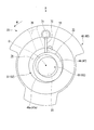
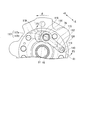
- FIG. 6 is a cross-sectional view of a compression mechanism portion in a portion corresponding to a line F4-F4 in FIG.
- the Z direction is the axial direction of the shaft 31.
- the + Z side which is the first side in the axial direction is, for example, the upper side in the vertical direction.
- the ⁇ Z side which is the second side in the axial direction, is, for example, the lower side in the vertical direction.
- the Z direction may be referred to as the axial direction Z.
- the R direction is the radial direction of the shaft 31.
- the + R side is the outer side in the radial direction and the side away from the central axis of the shaft 31.
- the ⁇ R direction is on the inner side in the radial direction and closer to the central axis of the shaft 31.
- the R direction may be referred to as the radial direction R.
- the ⁇ direction is the circumferential direction of the central axis of the shaft 31.
- the ⁇ direction may be referred to as the circumferential direction ⁇ .
- FIG. 1 is a schematic configuration diagram of a refrigeration cycle apparatus 1 including a cross-sectional view of a rotary compressor 2 of the present embodiment.
- a refrigeration cycle apparatus 1 includes a rotary compressor 2, a condenser 3 as a radiator connected to the rotary compressor 2, an expansion device 4 connected to the condenser 3, And an evaporator 5 as a heat absorber connected to the expansion device 4.
- the rotary compressor 2 is a so-called rotary compressor.
- the rotary compressor 2 compresses a low-pressure gas refrigerant (fluid) taken inside to form a high-temperature / high-pressure gas refrigerant.
- the specific configuration of the rotary compressor 2 will be described later.
- the condenser 3 dissipates heat from the high-temperature and high-pressure gas refrigerant discharged from the rotary compressor 2, and converts the high-temperature and high-pressure gas refrigerant into a high-pressure liquid refrigerant.
- the expansion device 4 lowers the pressure of the high-pressure liquid refrigerant sent from the condenser 3 so that the high-pressure liquid refrigerant becomes a low-temperature / low-pressure liquid refrigerant.
- the evaporator 5 vaporizes the low-temperature and low-pressure liquid refrigerant sent from the expansion device 4 to make a low-pressure gas refrigerant.
- the evaporator 5 when the low-pressure liquid refrigerant is vaporized, the surroundings are cooled by taking the heat of vaporization from the surroundings.
- the low-pressure gaseous refrigerant that has passed through the evaporator 5 is taken into the rotary compressor 2 described above.
- the refrigerant that is the working fluid circulates while changing phase between the gas refrigerant and the liquid refrigerant, and dissipates heat in the process of phase change from the gas refrigerant to the liquid refrigerant. It absorbs heat in the process of phase change from liquid refrigerant to gaseous refrigerant. And heating, cooling, etc. are performed using these heat dissipation and heat absorption.
- the rotary compressor 2 includes a compressor body 11 and an accumulator 12.
- the accumulator 12 is a so-called gas-liquid separator.
- the accumulator 12 is provided between the evaporator 5 and the compressor body 11 described above.
- the accumulator 12 is connected to a plurality of cylinders 41 and 42 of the compressor body 11 through a suction pipe 21.
- the accumulator 12 supplies the gas refrigerant vaporized by the evaporator 5 to the compressor body 11.
- the compressor body 11 accommodates a shaft 31, an electric motor part 32 that rotates the shaft 31, a compression mechanism part 33 that compresses a gaseous refrigerant by the rotation of the shaft 31, and the shaft 31, the electric motor part 32, and the compression mechanism part 33.
- the cylindrical case 34 is provided.
- the shaft 31 and the case 34 are arranged coaxially with respect to the axis O.
- the motor unit 32 is disposed in the case 34 on the + Z side (upper side in FIG. 1) along the axis O.
- the compression mechanism section 33 is disposed in the case 34 on the ⁇ Z side (lower side in FIG. 1) along the axis O.
- the electric motor section 32 is a so-called inner rotor type DC brushless motor.
- the electric motor unit 32 includes a stator 36 and a rotor 37.
- the stator 36 is formed in a cylindrical shape and is fixed to the inner wall surface of the case 34 by shrink fitting or the like.
- the rotor 37 is disposed inside the stator 36.
- the rotor 37 is connected to the upper part of the shaft 31.
- the rotor 37 rotates the shaft 31 by supplying current to a coil provided in the stator 36.
- the compression mechanism unit 33 includes a plurality of cylinders 41, 42, a partition plate 43, a main bearing 44, a sub bearing 45, a plurality of rollers 46, 47, a main muffler member 130, and a sub muffler member 180. .
- the plurality of cylinders includes a first cylinder 41 and a second cylinder 42.
- the first cylinder 41 and the second cylinder 42 are disposed so as to overlap in the axial direction Z with a gap between each other.
- Each of the first cylinder 41 and the second cylinder 42 is formed in a cylindrical shape opened in the axial direction Z.
- an internal space serving as the first cylinder chamber 51 is formed in the first cylinder 41.
- an internal space serving as a second cylinder chamber 52 is formed.
- the suction pipe 21 described above is individually connected to each of the first cylinder 41 and the second cylinder 42.
- the first and second cylinder chambers 51 and 52 are supplied with gas refrigerant separated by the accumulator 12 through the suction pipe 21.
- the partition plate 43 is disposed between the first cylinder 41 and the second cylinder 42 and is sandwiched between the first cylinder 41 and the second cylinder 42.
- the partition plate 43 includes a first partition plate 140 and a second partition plate 160.
- the first partition plate 140 faces the internal space of the first cylinder 41 and defines one surface of the first cylinder chamber 51.
- the second partition plate 160 faces the internal space of the second cylinder 42 and defines one surface of the second cylinder chamber 52.
- the partition plate 43 is provided with an opening 55 through which the shaft 31 passes in the axial direction Z. A specific configuration of the partition plate 43 will be described later.
- the main bearing 44 is located on the side of the motor unit 32 that is opposite to the first partition plate 140 with respect to the first cylinder 41.
- the main bearing 44 faces the internal space of the first cylinder 41 from the side opposite to the first partition plate 140 and defines another surface of the first cylinder chamber 51.
- a specific configuration of the main bearing 44 will be described later.
- the auxiliary bearing 45 is located on the side opposite to the second partition plate 160 with respect to the second cylinder 42, which is on the side opposite to the electric motor 32.
- the auxiliary bearing 45 faces the internal space of the second cylinder 42 from the side opposite to the second partition plate 160 and defines another surface of the second cylinder chamber 52.
- the shaft 31 described above passes through the first cylinder 41, the second cylinder 42, and the partition plate 43, and is rotatably supported by the main bearing 44 and the sub bearing 45.
- the shaft 31 is provided with a first eccentric portion 61 and a second eccentric portion 62.
- the first eccentric portion 61 is provided in a portion of the shaft 31 corresponding to the first cylinder chamber 51 and is disposed in the first cylinder chamber 51.
- the second eccentric portion 62 is provided in a portion corresponding to the second cylinder chamber 52 in the shaft 31 and is disposed in the second cylinder chamber 52.
- Each of the first eccentric portion 61 and the second eccentric portion 62 is formed in a cylindrical shape along the axial direction Z.
- the first eccentric portion 61 and the second eccentric portion 62 are eccentric by the same amount in the radial direction R with respect to the axis O.
- the first eccentric portion 61 and the second eccentric portion 62 are formed, for example, in the same shape and the same size in a plan view as viewed from the axial direction Z, and are arranged with a phase difference of 180 ° in the circumferential direction ⁇ .
- the plurality of rollers includes a first roller 46 and a second roller 47.
- Each of the first roller 46 and the second roller 47 is formed in a cylindrical shape along the axial direction Z.
- the first roller 46 is disposed on the outer peripheral side of the first eccentric portion 61.
- the second roller 47 is disposed on the outer peripheral side of the second eccentric portion 62.
- Each of the first roller 46 and the second roller 47 is configured so that the outer circumferential surfaces 46a, 47a of the rollers 46, 47 are in sliding contact with the inner circumferential surfaces of the cylinders 41, 42 as the shaft 31 rotates. It rotates eccentrically inside 52 (see FIG. 2).
- the internal configuration of the cylinder will be described.
- the internal configuration of the first cylinder 41 and the internal configuration of the second cylinder 42 are substantially the same except for portions that differ depending on the phase difference between the eccentric portions 61 and 62 and the rollers 46 and 47. Therefore, here, the internal configuration of the first cylinder 41 will be described as a representative.
- the structure which has the same function as the 1st cylinder 41 in the 2nd cylinder 42 is attached
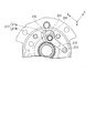
- FIG. 2 is a cross-sectional view of the compression mechanism section 33 taken along line F2-F2 of FIG.
- a vane groove 71 extending outward in the radial direction R is provided on the inner peripheral surface of the first cylinder 41.
- the vane groove 71 is formed over the entire first cylinder 41 in the axial direction Z.
- a vane 72 slidable along the radial direction R is inserted into the vane groove 71.
- the vane 72 is urged inward in the radial direction R by an urging means (not shown), and a tip portion of the vane 72 is in contact with the outer peripheral surface 46 a of the first roller 46 in the first cylinder chamber 51.
- the vane 72 partitions the inside of the first cylinder chamber 51 into a suction chamber 74 and a compression chamber 75.
- the vane 72 advances and retreats in the first cylinder chamber 51 with the eccentric rotation of the first roller 46.
- a suction operation for sucking the gaseous refrigerant into the first cylinder chamber 51 and a compression operation for compressing the gaseous refrigerant in the first cylinder chamber 51 are performed.
- the first cylinder 41 is provided with a suction hole 76 and a discharge groove 77.
- the suction hole 76 passes through the first cylinder 41 from the first cylinder chamber 51 toward the outside in the radial direction R.
- the suction pipe 21 described above is connected to the outer end of the suction hole 76 in the radial direction R.
- the inner end of the suction hole 76 in the radial direction R communicates with the suction chamber 74 of the first cylinder chamber 51.
- the suction hole 76 allows the gaseous refrigerant sent from the suction pipe 21 to flow into the suction chamber 74 of the first cylinder chamber 51.
- the discharge groove 77 is provided in the compression chamber 75.
- the discharge groove 77 is provided along the axial direction Z on the inner peripheral surface of the first cylinder 41 and communicates with a main bearing discharge hole 78 (see FIG. 1) of the main bearing 44.
- the discharge groove 77 guides the gas refrigerant compressed in the compression chamber 75 to the main bearing discharge hole 78 of the main bearing 44.
- the discharge groove 77 provided in the second cylinder 42 communicates with the auxiliary bearing discharge hole 79 (see FIG. 1) of the auxiliary bearing 45.
- the discharge groove 77 of the second cylinder 42 guides the gas refrigerant compressed in the compression chamber 75 to the sub bearing discharge hole 79 of the sub bearing 45.
- the main muffler member 130 forms a main muffler chamber 105 between the main bearing 44 and the main muffler member 130.
- the gaseous refrigerant compressed in the compression chamber 75 of the first cylinder 41 (hereinafter sometimes referred to as compressed gas) is discharged from the main bearing discharge hole 78 into the main muffler chamber 105.
- the main muffler chamber 105 has a main muffler chamber discharge port 106.
- the compressed gas discharged into the main muffler chamber 105 is discharged into the case 34 from the main muffler chamber discharge port 106.
- a specific configuration of the main muffler member 130 will be described later.
- the secondary muffler member 180 forms a secondary muffler chamber 185 between the secondary bearing 45.
- the gaseous refrigerant compressed in the compression chamber 75 of the second cylinder 42 is discharged from the auxiliary bearing discharge hole 79 to the auxiliary muffler chamber 185.
- the sub muffler chamber 185 communicates with the main muffler chamber 105 through through holes (not shown) formed in the second cylinder 42, the partition plate 43, and the first cylinder 41. Therefore, the compressed gas discharged to the sub muffler chamber 185 is discharged from the main muffler chamber discharge port 106 into the case 34.
- the case 34 has a discharge pipe 35 on the + Z side of the rotor 37 of the electric motor unit 32.
- the discharge pipe 35 discharges the compressed gas discharged into the case 34 to components constituting the refrigeration cycle apparatus outside the case 34 such as the condenser 3.
- the oil supply passage 80 provided in the compression mechanism unit 33 will be described.
- the internal configuration of the first eccentric portion 61 and the internal configuration of the second eccentric portion 62 are substantially the same. Therefore, here, the internal configuration of the first eccentric portion 61 will be described as a representative.
- FIG. 3 is an enlarged view around the main bearing 44 in the P part of FIG.
- the oil supply passage 80 includes a main passage 81 provided in the shaft 31, a sub passage 82 and a communication passage 84 provided in the first eccentric portion 61.
- the main passage 81 is provided coaxially with the axis O and is formed inside the shaft 31.
- the main passage 81 extends inside the shaft 31 along the axial direction Z.
- the main passage 81 is open to the outside of the shaft 31 at the end of the shaft 31 supported by the sub bearing 45.
- the lubricating oil J is accommodated in the case 34, and a part of the compression mechanism portion 33 is immersed in the lubricating oil J.
- Lubricating oil J accommodated in the case 34 flows into the main passage 81.
- pump means such as a torsion plate that pumps the lubricating oil J into the main passage 81 as the shaft 31 rotates is provided inside the main passage 81.
- the sub-passage 82 is a groove provided on the outer peripheral surface 61a of the eccentric portion 61, for example.
- the sub passage 82 is formed between the outer peripheral surface 61 a of the eccentric portion 61 and the inner peripheral surface 46 b of the roller 46.
- the sub passage 82 extends along the axial direction Z and is formed over the entire eccentric portions 61 and 62 in the axial direction Z.
- the communication path 84 is provided in the eccentric portion 61 along the radial direction R.
- the communication passage 84 is provided between the main passage 81 and the sub passage 82 and connects the main passage 81 and the sub passage 82.
- the lubricating oil J in the main passage 81 is supplied to the sub-passage 82 through the communication passage 84 due to the centrifugal force accompanying the rotation of the shaft 31.
- the lubricating oil J supplied to the sub passage 82 is supplied from the sub passage 82 to the sliding portion of the compression mechanism portion 33.
- the main bearing 44 has a bearing portion 100 and a closing portion 110.
- the bearing portion 100 and the closing portion 110 are integrally formed of a metal material.
- the main bearing 44 is formed by machining a part after casting the whole. Therefore, most of the outer surface of the main bearing 44 is formed with a casting surface.
- the bearing unit 100 is disposed between the electric motor unit 32 and the compression mechanism unit 33 in the axial direction Z, and supports the outer periphery of the shaft 31.
- the bearing unit 100 is formed in a cylindrical shape.
- the ⁇ Z side of the bearing portion 100 is formed with a constant outer diameter.
- a small diameter portion 102 having an outer diameter smaller than the ⁇ Z side is formed on the + Z side of the bearing portion 100.
- the small diameter portion 102 is formed to taper toward the + Z side.
- the closing part 110 closes the + Z side (third side) of the first cylinder chamber 51 of the compression mechanism part 33.
- the closing part 110 is formed in a disk shape.
- the closing portion 110 is continuous with the end portion on the ⁇ Z side of the bearing portion 100. A more specific configuration of the blocking unit 110 will be described later.
- the main muffler member 130 is formed of a steel plate material or the like.
- the main muffler member 130 is disposed on the + R side of the bearing portion 100 of the main bearing 44.
- the main muffler member 130 forms a main muffler chamber 105 with the main bearing 44.
- a flange portion 138 that extends to the + R side is formed at the ⁇ Z side end of the main muffler member 130.
- the flange portion 138 is fixed to the end surface on the + Z side of the closing portion 110 of the main bearing 44.
- the main muffler member 130 is formed in a funnel shape so as to taper toward the + Z side.
- a rectifying portion 134 that extends along the axial direction Z with a constant inner diameter is formed.
- the rectifying unit 134 is arranged coaxially with the bearing unit 100 of the main bearing 44.
- the rectification unit 134 rectifies the flow of the compressed gas so as to be annular and toward the + Z side.
- An annular main muffler chamber discharge port 106 is formed between the inner peripheral surface of the rectifying unit 134 and the outer peripheral surface 100 a of the bearing unit 100 of the main bearing 44.
- the main muffler chamber discharge port 106 is formed at the + Z side end of the rectifying unit 134.
- the main muffler chamber discharge port 106 discharges compressed gas from the main muffler chamber 105 into the case 34.
- the rotor 37 has a large inner diameter portion 92 and a compressed gas flow path 94.
- the large inner diameter portion (counter bore) 92 is formed at a certain depth from the end surface on the ⁇ Z side.
- the large inner diameter portion 92 is formed in a ring shape over the entire circumference of the shaft 31 and has an inner diameter larger than that of the portion to which the shaft 31 is connected.
- the small diameter portion 102 of the bearing portion 100 of the main bearing 44 is inserted into the large inner diameter portion 92. Thereby, the rotor 37 and the main bearing 44 overlap in the axial direction Z. Therefore, the rotary compressor 2 can be reduced in size in the axial direction Z.
- the lubricating oil J that has been pumped into the oil supply passage 80 of the shaft 31 and not used for the lubrication of the compression mechanism portion 33 may be discharged from the outer peripheral surface of the shaft 31 into the large inner diameter portion 92.
- the compressed gas flow path 94 passes through the rotor 37 from the bottom surface of the large inner diameter portion 92 to the + Z side end surface of the rotor 37.
- a plurality of compressed gas passages 94 are formed at intervals in the circumferential direction ⁇ .
- the compressed gas discharge operation will be described in detail.
- the gaseous refrigerant (compressed gas) compressed in the first cylinder chamber 51 is discharged from the main bearing discharge hole 78 to the main muffler chamber 105.
- the compressed gas discharged into the main muffler chamber 105 is discharged into the case 34 from the main muffler chamber discharge port 106.
- the electric motor unit 32 has a space that penetrates the electric motor unit 32 in the axial direction Z, such as a compressed gas passage 94 formed in the rotor 37.
- the compressed gas discharged to the ⁇ Z side of the motor part 32 inside the case 34 flows to the + Z side of the motor part 32 through a space such as the compressed gas channel 94.
- the compressed gas that has flowed to the + Z side of the electric motor unit 32 is discharged from the discharge pipe 35 (see FIG. 1) to the components of the refrigeration cycle apparatus.
- the lubricating oil J accommodated in the case 34 is pumped up into the oil supply passage 80 of the shaft 31 and supplied to the sliding portion of the compression mechanism 33. Therefore, the gaseous refrigerant (compressed gas) compressed in the first cylinder chamber 51 contains the lubricating oil J.
- compressed gas containing the lubricating oil J is supplied to the components of the refrigeration cycle apparatus, the efficiency of the components of the refrigeration cycle apparatus decreases.
- the compressed gas containing the lubricating oil J is discharged to the outside of the rotary compressor 2, the lubricating oil J is insufficient in the compression mechanism portion 33.
- the outer peripheral surface 100a of the bearing portion 100 of the main bearing 44 that forms the main muffler chamber discharge port 106 is arranged on the + R side from the inner peripheral surface 92a of the large inner diameter portion 92. That is, the distance from the axis O to the outer peripheral surface 100a of the bearing portion 100 (the radius of the outer peripheral surface 100a) is R1. The distance from the axis O to the inner peripheral surface 92a of the large inner diameter portion 92 (the radius of the inner peripheral surface 92a) is R2. At this time, the rotary compressor 2 of the present embodiment satisfies R1> R2.
- the compressed gas 108 discharged in the + Z direction from the main muffler chamber discharge port 106 collides with the ⁇ Z side end surface of the rotor 37.
- the lubricating oil 108a contained in the compressed gas 108 is blown in the + R direction by centrifugal force.
- the gaseous refrigerant 108 b contained in the compressed gas 108 flows into the large inner diameter portion 92.
- the gas refrigerant 108 b flows into the compressed gas passage 94 formed on the bottom surface of the large inner diameter portion 92 and is discharged to the outside from the discharge pipe 35. Thereby, the lubricating oil contained in the compressed gas can be separated.
- a flange disk 96 is attached to the end of the shaft 31 on the + Z side.
- the flange disk 96 extends to the + R side around the entire shaft 31.
- the flange disk 96 is disposed so as to cover the + Z side of the compressed gas flow path 94.
- the compressed gas discharged to the + Z side from the compressed gas flow path 94 collides with the flange disk 96. Since the flange disk 96 rotates with the shaft 31, the lubricating oil contained in the compressed gas is blown in the + R direction by centrifugal force. As described above, the flange disk 96 also separates the lubricating oil from the compressed gas.
- the distance between the main muffler chamber discharge port 106 and the rotor 37 in the axial direction Z is L1.
- the depth of the large inner diameter portion 92 in the axial direction Z is L2.
- the rotary compressor 2 of the present embodiment satisfies L1 ⁇ L2. Since L1 is smaller than L2, most of the compressed gas 108 discharged from the main muffler chamber discharge port 106 collides with the end surface of the rotor 37 on the ⁇ Z side. Thereby, the lubricating oil contained in the compressed gas can be separated. Further, since L2 is larger than L1, many portions of the bearing portion 100 can be disposed inside the large inner diameter portion 92. Therefore, the rotary compressor 2 can be reduced in size in the axial direction Z.
- the opening area perpendicular to the axial direction Z of the main muffler chamber discharge port 106 is S1.
- the passage area between the inner peripheral surface of the large inner diameter portion 92 and the outer peripheral surface 100a of the small diameter portion 102 of the bearing portion 100 on the end surface on the ⁇ Z side of the rotor 37 is S2.
- the rotary compressor 2 of the present embodiment satisfies S1 ⁇ S2. Since S1 is smaller than S2, the discharge speed of the compressed gas from the main muffler chamber discharge port 106 is increased. Therefore, most of the discharged compressed gas collides with the end surface on the ⁇ Z side of the rotor 37. Thereby, the lubricating oil contained in the compressed gas can be separated. Further, since S2 is larger than S1, the gas refrigerant 108b included in the compressed gas 108 is likely to flow into the large inner diameter portion 92. Thereby, the lubricating oil contained in the compressed gas can be separated.
- the opening area perpendicular to the axial direction Z of the main muffler chamber discharge port 106 is S1.
- the total opening area of the discharge holes of the compression mechanism 33 is S3.
- the total opening area S3 of the discharge holes of the compression mechanism section 33 is the sum of the opening areas of all the compressed gas discharge holes in the compression mechanism section 33. That is, the total opening area of the discharge holes of the compression mechanism portion 33 is the sum of the opening areas of the main bearing discharge holes 78, the auxiliary bearing discharge holes 79, the first partition plate discharge holes 143 and the second partition plate discharge holes described later. It is.
- the rotary compressor 2 of the present embodiment satisfies S1 ⁇ S3.
- FIG. 4 is a cross-sectional view of the compression mechanism section 33 taken along line F4-F4 of FIG.
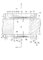
- FIG. 5 is a cross-sectional view of the compression mechanism section 33 taken along line F5-F5 in FIG.
- the valve body 120 and the stopper 122 are not shown.
- the closing portion 110 has a main bearing discharge hole 78, a valve body 120, a stopper 122, and a valve body fixing portion 124.
- the X direction is defined as follows. As shown in FIG. 4, the direction in which the line connecting the center of the main bearing discharge hole 78 and the center of the valve body fixing portion 124 extends is the X direction. In the X direction, the main bearing discharge hole 78 side is the + X side, and the valve body fixing portion 124 side is the -X side.
- the closing part 110 closes the + Z side (third side) of the first cylinder chamber 51 of the compression mechanism part 33.
- the closing part 110 is formed in a disk shape.
- a recess 111 is formed on the surface of the closing portion 110 on the + Z side.
- a valve body 120 and a stopper 122 are accommodated in the recess 111.
- the recess 111 extends along the X direction.
- a thin bottom wall 112 is formed at the bottom of the recess 111.
- the main bearing discharge hole 78 is formed on the + X side of the recess 111.
- the main bearing discharge hole 78 is formed through the bottom wall 112.
- the valve body 120 is formed in a plate shape from a metal material or the like.
- the valve body 120 is disposed on the + Z side of the bottom wall 112.
- the valve body 120 extends in the X direction from the main bearing discharge hole 78 to the valve body fixing portion 124.
- the + X side valve head of the valve body 120 moves in the Z direction to open and close the main bearing discharge hole 78.
- the stopper 122 is formed in a plate shape thicker than the valve body 120 using a metal material or the like.
- the stopper 122 is disposed on the + Z side of the valve body 120.
- the stopper 122 extends in the X direction from the main bearing discharge hole 78 to the valve body fixing portion 124.
- the stopper 122 is curved toward the + Z side from the ⁇ X side to the + X side.
- the stopper 122 restricts the valve head on the + X side of the valve body 120 from being excessively displaced to the + Z side.
- the valve body fixing portion 124 is formed at the ⁇ X side end of the recess 111.
- the valve body fixing part 124 has a rivet or a screw.
- the valve body fixing part 124 fixes the ⁇ X side ends of the valve body 120 and the stopper 122 to the bottom wall 112 of the recess 111.
- the shape of the surface on the + Z side (hereinafter simply referred to as the surface) of the bottom wall 112 of the recess 111 of the closing portion 110 will be described.
- the surface of the bottom wall 112 protrudes to the + Z side (third side) that is the anti-cylinder chamber 51 side to form a valve seat 114.
- the surface of the bottom wall 112 protrudes to the + Z side in the same manner as the valve seat 114.
- the surface of the bottom wall 112 is formed lower than the valve seat 114.
- the first region 115 extends from the periphery of the valve seat 114 to the vicinity of the valve body fixing portion 124.
- the valve body 120 fixed to the valve body fixing portion 124 reliably contacts the valve seat 114 and closes the main bearing discharge hole 78.
- an inclined surface 119 is formed at the end of the bottom wall 112 on the + X side.
- the inclined surface 119 extends to the + X side and the + Z side from the periphery of the main bearing discharge hole 78 to the opening edge of the recess 111.
- the inclined surface 119 is formed in a curved surface shape in which the inclination gradually increases from the ⁇ X side to the + X side.
- the compressed gas discharged in the + Z direction from the main bearing discharge hole 78 collides with the valve body 120 and changes the course in the + X direction.
- the compressed gas that has advanced in the + X direction is guided in flow by the inclined surface 119 and is discharged in the + Z direction from the + X side end of the recess 111.
- the inclined surface 119 guides the compressed gas discharged from between the valve seat 114 and the valve body 120 to the + Z side.
- the compressed gas can be discharged from the main muffler chamber discharge port 106 to the + Z side at a high speed.
- the recess 111 extends in the circumferential direction ⁇ from the + X side end along the outer periphery of the closing portion 110.
- the compressed gas is discharged in the + Z direction from the end of the recess 111 in the circumferential direction ⁇ .
- a second region 117 that is recessed toward the ⁇ Z side is formed between the first region 115 around the valve seat 114 and the inclined surface 119.
- the second region 117 is formed to be recessed in the ⁇ Z side substantially perpendicularly from the + X side end of the first region 115. From the second region 117 to the inclined surface 119, the surface of the bottom wall 112 continuously changes to the + Z side.
- the portion in the axial direction Z where the position in the ⁇ Z side from the first region 115 is included in the second region 117.
- the second region 117 is hatched.
- the second region 117 is recessed to the ⁇ Z side from the first region 115. Therefore, the flow resistance of the compressed gas discharged in the + X direction from between the valve seat 114 and the valve body 120 is reduced. Thereby, the compressed gas is discharged to the + Z side at high speed from the main muffler chamber discharge port 106 shown in FIG. Therefore, most of the discharged compressed gas collides with the end surface on the ⁇ Z side of the rotor 37. Thereby, the lubricating oil contained in the compressed gas can be separated.
- the thickness of the bottom wall 112 is thinner in the second region 117 than in the first region 115. Therefore, securing the rigidity of the bottom wall 112 in the second region 117 becomes a problem.
- a portion of the second region 117 that overlaps the first cylinder chamber 51 when viewed from the axial direction Z is defined as an inner portion 117b. Since a large pressure is applied to the inner portion 117b from the first cylinder chamber 51, rigidity is required.
- a portion of the second region 117 that overlaps the first cylinder 41 around the first cylinder chamber 51 when viewed from the axial direction Z is defined as an outer portion 117a.
- the area of the outer portion 117a is larger than the area of the inner portion 117b. Therefore, even when the bottom wall 112 of the second region 117 is thinned, the rigidity of the bottom wall 112 in the second region 117 can be ensured.
- FIG. 6 is a cross-sectional view of the compression mechanism portion in a portion corresponding to the F4-F4 line in FIG. 3 as a modification of the embodiment. Description of the part which becomes the structure similar to embodiment is abbreviate
- the + X side end of the recess 211 extends as it is to the + X side without being extended in the circumferential direction ⁇ .
- the + X side end portion of the recess 211 extends in the Y direction orthogonal to the X direction and the Z direction.
- a second region 217 depressed toward the ⁇ Z side is formed between the first region 215 around the valve seat 214 and the inclined surface 219.
- the flow resistance of the compressed gas is small.
- the area of the outer portion 217a is larger than the area of the inner portion 217b. Thereby, the rigidity of the bottom wall 212 in the second region 217 can be ensured.
- the configuration of the partition plate 43 will be described in detail. Recently, it is desired to increase the capacity of the rotary compressor 2. However, it is difficult to expand the cylinder chambers 51 and 52 in the radial direction R due to the demand for common use of the case 34. Therefore, the cylinder chambers 51 and 52 are enlarged in the axial direction Z to increase the capacity of the rotary compressor 2. In the large capacity rotary compressor 2, the discharge amount of the compressed gas is increased. However, since it is difficult to expand the cylinder chambers 51 and 52 in the radial direction R, there is a limit to increasing the opening area of the main bearing discharge hole 78. Therefore, the large-capacity rotary compressor 2 has a partition plate discharge port, and discharges compressed gas to the partition plate.
- the partition plate 43 includes a first partition plate 140 and a second partition plate 160.
- the configuration of the first partition plate 140 and the configuration of the second partition plate 160 are substantially the same.
- the configuration of the first partition plate 140 will be described as a representative.
- the first partition plate 140 faces the internal space of the first cylinder 41 and defines one surface of the first cylinder chamber 51.
- the first partition plate 140 includes a first partition plate discharge hole 143, a valve body 150, a stopper 152, and a valve body fixing portion 154.
- the X ′ direction is defined as follows.
- the direction in which the line connecting the center of the first partition plate discharge hole 143 and the center of the valve body fixing portion 154 extends is the X ′ direction.
- the first partition plate discharge hole 143 side is the + X ′ side
- the valve body fixing portion 154 side is the ⁇ X ′ side.
- the first partition plate 140 closes the ⁇ Z side of the first cylinder chamber 51 of the compression mechanism 33.
- the first partition plate 140 is formed in a disc shape.
- a recess 141 is formed on the surface of the first partition plate 140 on the ⁇ Z side.
- the recess 141 houses the valve body 150 and the stopper 152.
- the concave portion 141 extends along the X ′ direction.
- a thin bottom wall 142 is formed at the bottom of the recess 141.
- the first partition plate discharge hole 143 is formed on the + X ′ side of the recess 141.
- the first partition plate discharge hole 143 is formed through the bottom wall 142. Since the first partition plate discharge hole 143 is formed in the thin bottom wall 142, the dead volume inside the first partition plate discharge hole 143 is small. Further, the volume of the concave portion 141 of the first partition plate 140 is smaller than the volume of the concave portion 111 of the closing portion 110 of the main bearing 44. Therefore, the flow rate of the compressed gas that can flow through the concave portion 141 of the first partition plate 140 is smaller than the flow rate of the compressed gas that can flow through the concave portion 111 of the closing portion 110. Therefore, the opening area of the first partition plate discharge hole 143 is smaller than the opening area of the main bearing discharge hole 78.
- the valve body 150 is formed in a plate shape from a metal material or the like.
- the valve body 150 is disposed on the ⁇ Z side of the bottom wall 142.
- the valve body 150 extends in the X ′ direction from the first partition plate discharge hole 143 to the valve body fixing portion 154.
- the valve head on the + X ′ side of the valve body 150 moves in the Z direction to open and close the first partition plate discharge hole 143.
- the stopper 152 is formed in a plate shape thicker than the valve body 150 using a metal material or the like.
- the stopper 152 is disposed on the ⁇ Z side of the valve body 150.
- the stopper 152 extends in the X ′ direction from the first partition plate discharge hole 143 to the valve body fixing portion 154.
- the stopper 152 is curved toward the ⁇ Z side from the ⁇ X ′ side to the + X ′ side.
- the stopper 152 restricts the valve head on the + X ′ side of the valve body 150 from being excessively displaced to the ⁇ Z side.
- the valve body fixing portion 154 is formed at the end portion on the ⁇ X ′ side of the concave portion 141.
- fixed part 154 has a rivet or a screw
- the valve body fixing portion 154 fixes the ⁇ X ′ side ends of the valve body 150 and the stopper 152 to the bottom wall 142 of the recess 141.
- the surface of the bottom wall 142 protrudes to the ⁇ Z side (third side) to form a valve seat 144.
- the surface of the bottom wall 142 protrudes to the ⁇ Z side in the same manner as the valve seat 144.
- the surface of the bottom wall 142 is formed lower than the valve seat 144.
- the first region 145 extends from the periphery of the valve seat 144 to the vicinity of the valve body fixing portion 154.
- the first partition plate 140 will be described in comparison with the closing portion 110 of the main bearing 44. As shown in FIG. 1, the first partition plate 140 is disposed between the first cylinder 41 and the second cylinder 42.
- the first eccentric portion 61 of the shaft 31 is disposed in the first cylinder chamber 51
- the second eccentric portion 62 of the shaft 31 is disposed in the second cylinder chamber 52.
- the first eccentric part 61 and the second eccentric part 62 are arranged with a phase difference of 180 ° in the circumferential direction ⁇ . Therefore, a large bending moment acts on a portion between the first eccentric portion 61 and the second eccentric portion 62 of the shaft 31 (hereinafter referred to as an intermediate portion) due to the rotation of the shaft 31. If the height of the 1st partition plate 140 is made high, the intermediate part of the shaft 31 will become long. Therefore, the intermediate portion of the shaft 31 is easily bent by the bending moment during rotation, and the reliability of the shaft 31 is reduced.
- a large pressure acts on the first partition plate 140 and the closing portion 110 from the first cylinder chamber 51. Accordingly, when the first partition plate 140 and the closing portion 110 are deformed, interference with the first roller 46 (see FIG. 3) occurs. Therefore, it is necessary to ensure the rigidity of the first partition plate 140 and the closing part 110.
- the height H2 of the first partition plate 140 in the axial direction Z is smaller than the height H1 of the closing portion 110 in the axial direction Z.
- the thickness T2 in the axial direction Z of the first region 145 of the bottom wall 142 of the first partition plate 140 is larger than the thickness T1 in the axial direction Z of the first region 115 of the bottom wall 112 of the closing portion 110. . Since the height H2 of the first partition plate 140 is small, the reliability of the shaft 31 can be ensured. Even if the height H2 of the first partition plate 140 is small, the thickness T2 of the bottom wall 142 is large, so that the rigidity of the first partition plate 140 can be ensured.
- the height H1 of the closing portion 110 is large, the rigidity of the closing portion 110 can be ensured even if the thickness T1 of the bottom wall 112 is small. Since the thickness T1 of the bottom wall 112 of the closing part 110 is small, the dead volume of the main bearing discharge hole 78 can be reduced.
- the relationship between the first partition plate 140 and the closed portion 110 of the main bearing 44 has been described, but the same applies to the relationship between the second partition plate 160 and the closed portion of the auxiliary bearing 45.
- the rotary compressor 2 of the present embodiment shown in FIG. 1 has the shaft 31, the electric motor unit 32, the compression mechanism unit 33, the main muffler member 130, and the case 34.
- the electric motor unit 32 includes a rotor 37 and a stator 36.
- the rotor 37 is disposed on the + Z side in the axial direction Z of the shaft 31 and is fixed to the shaft 31.
- the stator 36 is disposed on the + R side of the rotor 37.
- the compression mechanism 33 is disposed on the ⁇ Z side opposite to the + Z side in the axial direction Z of the shaft 31, and compresses the gas by the rotation of the shaft 31.
- the main muffler member 130 is disposed on the + R side of the bearing portion 100 of the main bearing 44 on the electric motor portion 32 side that constitutes the compression mechanism portion 33, and the main muffler chamber 105 into which the compressed gas compressed by the compression mechanism portion 33 is discharged.
- the main muffler chamber discharge port 106 is formed between the inner peripheral surface and the outer peripheral surface 100a of the bearing portion 100.
- the case 34 accommodates the shaft 31, the electric motor unit 32, the compression mechanism unit 33 and the main muffler member 130 inside, has a discharge pipe 35 on the + Z side, and stores the lubricating oil J at the bottom.
- the rotor 37 has a large inner diameter portion 92 and a compressed gas flow path 94.
- the large inner diameter portion 92 is formed on the end surface side on the ⁇ Z side.
- the compressed gas flow path 94 penetrates from the bottom surface of the large inner diameter portion 92 to the end surface on the + Z side.
- the outer peripheral surface 100 a of the bearing portion 100 that forms the main muffler chamber discharge port 106 is arranged on the + R side in the radial direction R from the inner peripheral surface 92 a of the large inner diameter portion 92.
- the compressed gas 108 discharged in the + Z direction from the main muffler chamber discharge port 106 collides with the ⁇ Z side end surface of the rotor 37.
- the lubricating oil 108a contained in the compressed gas 108 is blown in the + R direction by centrifugal force.
- the gaseous refrigerant 108 b contained in the compressed gas 108 flows into the large inner diameter portion 92.
- the gas refrigerant 108 b flows into the compressed gas passage 94 formed on the bottom surface of the large inner diameter portion 92 and is discharged to the outside from the discharge pipe 35. Thereby, the lubricating oil contained in the compressed gas can be separated.
- the rotary compressor 2 of the present embodiment when the distance between the main muffler chamber discharge port 106 and the rotor 37 in the axial direction Z is L1, and the depth of the large inner diameter portion 92 in the axial direction Z is L2, L1 ⁇ L2 is satisfied.
- L1 is smaller than L2
- the lubricating oil contained in the compressed gas can be separated.
- L2 is larger than L1, many portions of the bearing portion 100 can be disposed inside the large inner diameter portion 92. Therefore, the rotary compressor 2 can be reduced in size in the axial direction Z.
- the rotary compressor 2 is arranged so that a part of the bearing portion 100 is positioned in the large inner diameter portion 92 of the rotor 37, the opening area of the main muffler chamber discharge port 106 is S1, and the large inner diameter is set.
- S1 the passage area between the inner peripheral surface of the portion 92 and the outer peripheral surface 100a of the small-diameter portion 102 of the bearing portion 100 is S2, S1 ⁇ S2 is satisfied.
- S1 is smaller than S2
- the discharge speed of the compressed gas from the main muffler chamber discharge port 106 is increased. Therefore, most of the discharged compressed gas collides with the end surface on the ⁇ Z side of the rotor 37.
- the lubricating oil contained in the compressed gas can be separated. Further, since S2 is larger than S1, the gas refrigerant 108b included in the compressed gas 108 is likely to flow into the large inner diameter portion 92. Thereby, the lubricating oil contained in the compressed gas can be separated.
- the rotary compressor 2 of the present embodiment satisfies S1 ⁇ S3, where S1 is the opening area of the main muffler chamber discharge port 106 and S3 is the total opening area of the discharge holes of the compression mechanism section.
- the total opening area S3 of the discharge holes of the compression mechanism section is the sum of the opening areas of all the compressed gas discharge holes in the compression mechanism section 33.
- the compression mechanism portion 33 has a closing portion 110 of the main bearing 44.
- the closing part 110 closes the + Z side of the first cylinder chamber 51 that compresses the gas.
- the closing part 110 includes a main bearing discharge hole 78, a valve body 120, a valve seat 114, an inclined surface 119, and a second region 117.
- the valve body 120 opens and closes the main bearing discharge hole 78.
- the valve seat 114 protrudes from the periphery of the main bearing discharge hole 78 to the opposite side of the first cylinder chamber 51.
- the inclined surface 119 guides the compressed gas discharged from between the valve body 120 and the valve seat 114.
- the second region 117 is provided between the first region 115 around the valve seat 114 and the inclined surface 119 and is recessed from the first region 115 to the first cylinder chamber 51 side. According to this configuration, the second region 117 that is recessed to the ⁇ Z side from the first region 115 is provided. Therefore, the flow resistance of the compressed gas discharged from between the valve seat 114 and the valve body 120 is reduced. Thereby, the compressed gas 108 is discharged at high speed from the main muffler chamber discharge port 106 shown in FIG. Therefore, most of the discharged compressed gas collides with the end surface on the ⁇ Z side of the rotor 37. Thereby, the lubricating oil contained in the compressed gas can be separated.
- the refrigeration cycle apparatus 1 includes a rotary compressor 2, a condenser 3, an expansion device 4, and an evaporator 5 according to this embodiment.
- the condenser 3 is connected to the rotary compressor 2.
- the expansion device 4 is connected to the condenser 3.
- the evaporator 5 is connected to the expansion device 4.
- the refrigeration cycle apparatus 1 includes the rotary compressor 2 that can suppress the mixing of lubricating oil into the discharged compressed gas. Therefore, it is possible to suppress a decrease in efficiency of the evaporator and the condenser. Therefore, a highly efficient refrigeration cycle apparatus can be provided.
- the refrigeration cycle apparatus 1 includes the rotary compressor 2 that can prevent the lubricating oil J from being insufficient in the compression mechanism section 33. Therefore, a highly reliable refrigeration cycle apparatus can be provided.
- the bearing portion 100 and the closing portion 110 of the main bearing 44 of the embodiment are integrally formed.
- the bearing portion 100 and the closing portion 110 may be formed separately.
- the number of cylinders of the rotary compressor 2 of the embodiment is two, that is, the first cylinder 41 and the second cylinder 42.
- the number of cylinders may be one or three or more.
- the compression mechanism section 33 of the embodiment employs a rotary compressor in which rollers and blades are formed separately.
- the compression mechanism unit 33 may employ a swing type compressor in which rollers and blades are integrally formed.
- the outer peripheral surface 100a of the bearing portion 100 forming the main muffler chamber discharge port 106 is disposed on the + R side in the radial direction R from the inner peripheral surface 92a of the large inner diameter portion 92. The Thereby, mixing of the lubricating oil into the compressed gas discharged from the rotary compressor 2 can be suppressed.
Landscapes
- Engineering & Computer Science (AREA)
- Mechanical Engineering (AREA)
- General Engineering & Computer Science (AREA)
- Applications Or Details Of Rotary Compressors (AREA)
Abstract
実施形態の回転式圧縮機は、シャフトと、電動機部と、圧縮機構部と、マフラ部材と、ケースと、を持つ。マフラ部材は、圧縮機構部の軸受部との間にマフラ室を形成する。電動機部の回転子は、大内径部と、圧縮ガス流路とを有する。大内径部は、第2側の端面におけるシャフトの周囲に形成される。圧縮ガス流路は、大内径部の底面から第1側の端面にかけて回転子を貫通する。マフラ室吐出口を形成する軸受部の外周面は、大内径部の内周面より、径方向の外側に配置される。
Description
本発明の実施形態は、回転式圧縮機および冷凍サイクル装置に関する。
本願は、2017年3月15日に、日本に出願された特願2017-050156号に基づき優先権を主張し、その内容をここに援用する。
本願は、2017年3月15日に、日本に出願された特願2017-050156号に基づき優先権を主張し、その内容をここに援用する。
冷凍サイクル装置において回転式圧縮機が利用されている。回転式圧縮機は、シリンダの内部でローラを偏心回転させ、気体冷媒を圧縮して外部に送出する。回転式圧縮機の内部には潤滑油が収容されている。潤滑油は、回転式圧縮機の摺動部分に供給される。回転式圧縮機から吐出される圧縮ガスに潤滑油が混入すると、冷凍サイクル装置の蒸発器や放熱器の効率が低下する。また吐出される圧縮ガスに潤滑油が混入すると、回転式圧縮機内での潤滑油が不足する。
本発明が解決しようとする課題は、吐出される圧縮ガスへの潤滑油の混入を抑制することができる回転式圧縮機および冷凍サイクル装置を提供することである。
実施形態の回転式圧縮機は、シャフトと、電動機部と、圧縮機構部と、マフラ部材と、ケースと、を持つ。電動機部は、回転子と、固定子と、を有する。回転子は、前記シャフトの軸方向の第1側に配置され前記シャフトに固定される。固定子は、前記回転子の外側に配置される。圧縮機構部は、前記シャフトの軸方向における前記第1側とは反対の第2側に配置され、前記シャフトの回転によりガスを圧縮する。マフラ部材は、前記圧縮機構部を構成する前記電動機部側の軸受部の外側に配置され、前記圧縮機構部で圧縮された圧縮ガスが吐出されるマフラ室を形成するとともに、内周面と前記軸受部の外周面間にマフラ室吐出口を形成する。ケースは、前記シャフト、前記電動機部、前記圧縮機構部および前記マフラ部材を内部に収容するとともに、前記第1側に吐出管を有し底部に潤滑油を貯留する。前記回転子は、大内径部と、圧縮ガス流路と、を有する。大内径部は、前記第2側の端面側に形成される。圧縮ガス流路は、前記大内径部の底面から前記第1側の端面にかけて貫通する。前記マフラ室吐出口を形成する前記軸受部の外周面は、前記大内径部の内周面より、径方向の外側に配置される。
以下、実施形態の回転式圧縮機および冷凍サイクル装置を、図面を参照して説明する。本願において、Z方向、R方向およびθ方向は以下のように定義される。Z方向はシャフト31の軸方向である。軸方向の第1側である+Z側は、例えば鉛直方向の上側である。軸方向の第2側である-Z側は、例えば鉛直方向の下側である。なお、Z方向を軸方向Zと呼ぶ場合がある。R方向はシャフト31の径方向である。+R側は、径方向の外側であって、シャフト31の中心軸から離れる側である。-R方向は、径方向の内側であって、シャフト31の中心軸に近づく側である。なお、R方向を径方向Rと呼ぶ場合がある。θ方向は、シャフト31の中心軸の周方向である。なお、θ方向を周方向θと呼ぶ場合がある。
始めに、冷凍サイクル装置について簡単に説明する。
図1は、本実施形態の回転式圧縮機2の断面図を含む冷凍サイクル装置1の概略構成図である。
図1に示すように、冷凍サイクル装置1は、回転式圧縮機2と、回転式圧縮機2に接続された放熱器としての凝縮器3と、凝縮器3に接続された膨張装置4と、膨張装置4に接続された吸熱器としての蒸発器5とを備えている。
図1は、本実施形態の回転式圧縮機2の断面図を含む冷凍サイクル装置1の概略構成図である。
図1に示すように、冷凍サイクル装置1は、回転式圧縮機2と、回転式圧縮機2に接続された放熱器としての凝縮器3と、凝縮器3に接続された膨張装置4と、膨張装置4に接続された吸熱器としての蒸発器5とを備えている。
回転式圧縮機2は、いわゆるロータリ式の圧縮機である。回転式圧縮機2は、例えば、内部に取り込まれる低圧の気体冷媒(流体)を圧縮して高温・高圧の気体冷媒にする。なお、回転式圧縮機2の具体的な構成については後述する。
凝縮器3は、回転式圧縮機2から吐出される高温・高圧の気体冷媒から放熱して、高温・高圧の気体冷媒を高圧の液体冷媒にする。
膨張装置4は、凝縮器3から送り込まれる高圧の液体冷媒の圧力を下げ、高圧の液体冷媒を低温・低圧の液体冷媒にする。
蒸発器5は、膨張装置4から送り込まれる低温・低圧の液体冷媒を気化させ、低圧の気体冷媒にする。そして、蒸発器5において、低圧の液体冷媒が気化する際に周囲から気化熱を奪うことで周囲が冷却される。なお、蒸発器5を通過した低圧の気体冷媒は、上述した回転式圧縮機2の内部に取り込まれる。
膨張装置4は、凝縮器3から送り込まれる高圧の液体冷媒の圧力を下げ、高圧の液体冷媒を低温・低圧の液体冷媒にする。
蒸発器5は、膨張装置4から送り込まれる低温・低圧の液体冷媒を気化させ、低圧の気体冷媒にする。そして、蒸発器5において、低圧の液体冷媒が気化する際に周囲から気化熱を奪うことで周囲が冷却される。なお、蒸発器5を通過した低圧の気体冷媒は、上述した回転式圧縮機2の内部に取り込まれる。
このように、本実施形態の冷凍サイクル装置1では、作動流体である冷媒が気体冷媒と液体冷媒との間で相変化しながら循環し、気体冷媒から液体冷媒に相変化する過程で放熱し、液体冷媒から気体冷媒に相変化する過程で吸熱する。そして、これらの放熱や吸熱を利用して暖房や冷房などが行われる。
次に、上述した回転式圧縮機2の具体的な構成について説明する。
本実施形態の回転式圧縮機2は、圧縮機本体11と、アキュムレータ12とを備える。
アキュムレータ12は、いわゆる気液分離器である。アキュムレータ12は、上述した蒸発器5と圧縮機本体11との間に設けられている。アキュムレータ12は、吸い込みパイプ21を通じて圧縮機本体11の複数のシリンダ41,42に接続されている。アキュムレータ12は、蒸発器5で気化された気体冷媒を圧縮機本体11に供給する。
本実施形態の回転式圧縮機2は、圧縮機本体11と、アキュムレータ12とを備える。
アキュムレータ12は、いわゆる気液分離器である。アキュムレータ12は、上述した蒸発器5と圧縮機本体11との間に設けられている。アキュムレータ12は、吸い込みパイプ21を通じて圧縮機本体11の複数のシリンダ41,42に接続されている。アキュムレータ12は、蒸発器5で気化された気体冷媒を圧縮機本体11に供給する。
圧縮機本体11は、シャフト31と、シャフト31を回転させる電動機部32と、シャフト31の回転によって気体冷媒を圧縮する圧縮機構部33と、これらシャフト31、電動機部32および圧縮機構部33を収容した円筒状のケース34とを備えている。
シャフト31およびケース34は、軸線Oに対して同軸状に配置されている。電動機部32は、ケース34のなかで、軸線Oに沿う+Z側(図1における上側)に配置されている。圧縮機構部33は、ケース34のなかで、軸線Oに沿う-Z側(図1における下側)に配置されている。
電動機部32は、いわゆるインナーロータ型のDCブラシレスモータである。具体的には、電動機部32は、固定子36と、回転子37とを備える。固定子36は、筒状に形成され、ケース34の内壁面に焼嵌めなどによって固定されている。回転子37は、固定子36の内側に配置されている。回転子37は、シャフト31の上部に連結されている。回転子37は、固定子36に設けられたコイルに電流が供給されることで、シャフト31を回転駆動する。
次に、圧縮機構部33について説明する。
圧縮機構部33は、複数のシリンダ41,42と、仕切板43と、主軸受44と、副軸受45と、複数のローラ46,47と、主マフラ部材130と、副マフラ部材180とを備える。
圧縮機構部33は、複数のシリンダ41,42と、仕切板43と、主軸受44と、副軸受45と、複数のローラ46,47と、主マフラ部材130と、副マフラ部材180とを備える。
複数のシリンダは、第1シリンダ41と、第2シリンダ42とを含む。第1シリンダ41および第2シリンダ42は、互いの間に隙間を空けて軸方向Zに重ねて配置されている。第1シリンダ41および第2シリンダ42の各々は、軸方向Zに開口した筒状に形成されている。これにより、第1シリンダ41には、第1シリンダ室51となる内部空間が形成されている。第2シリンダ42には、第2シリンダ室52となる内部空間が形成されている。第1シリンダ41および第2シリンダ42の各々には、上述した吸い込みパイプ21が個別に接続されている。第1シリンダ室51および第2シリンダ室52には、アキュムレータ12で気液分離された気体冷媒が吸い込みパイプ21を通じて供給される。
仕切板43は、第1シリンダ41と第2シリンダ42との間に配置され、第1シリンダ41と第2シリンダ42との間に挟まれている。仕切板43は、第1仕切板140と、第2仕切板160と、を有する。第1仕切板140は、第1シリンダ41の内部空間に面して、第1シリンダ室51の一面を規定している。同様に、第2仕切板160は、第2シリンダ42の内部空間に面して、第2シリンダ室52の一面を規定している。また、仕切板43には、軸方向Zにシャフト31が通される開口部55が設けられている。仕切板43の具体的な構成については後述する。
主軸受44は、第1シリンダ41に対して第1仕切板140とは反対側である電動機部32側に位置する。主軸受44は、第1仕切板140とは反対側から第1シリンダ41の内部空間に面して、第1シリンダ室51の別の一面を規定している。主軸受44の具体的な構成については後述する。一方で、副軸受45は、第2シリンダ42に対して第2仕切板160とは反対側である反電動機部32側に位置する。副軸受45は、第2仕切板160とは反対側から第2シリンダ42の内部空間に面して、第2シリンダ室52の別の一面を規定している。
ここで、上述したシャフト31は、第1シリンダ41,第2シリンダ42、および仕切板43を貫通するとともに、主軸受44と副軸受45とによって回転可能に支持されている。シャフト31には、第1偏心部61と、第2偏心部62とが設けられている。第1偏心部61は、シャフト31のなかで第1シリンダ室51に対応する部分に設けられ、第1シリンダ室51内に配置されている。第2偏心部62は、シャフト31のなかで第2シリンダ室52に対応する部分に設けられ、第2シリンダ室52内に配置されている。第1偏心部61および第2偏心部62の各々は、軸方向Zに沿う円柱状に形成されている。第1偏心部61および第2偏心部62は、軸線Oに対して径方向Rに同一量ずつ偏心している。第1偏心部61および第2偏心部62は、軸方向Zから見た平面視で例えば同形同大に形成されるとともに、周方向θに180°の位相差をもって配置されている。
複数のローラは、第1ローラ46と、第2ローラ47とを含む。第1ローラ46および第2ローラ47の各々は、軸方向Zに沿う筒状に形成されている。第1ローラ46は、第1偏心部61の外周側に配置されている。一方で、第2ローラ47は、第2偏心部62の外周側に配置されている。第1ローラ46および第2ローラ47の各々は、シャフト31の回転に伴い、各ローラ46,47の外周面46a,47aを各シリンダ41,42の内周面に摺接させながらシリンダ室51,52の内側で偏心回転する(図2参照)。
次に、シリンダの内部構成について説明する。
ここで、第1シリンダ41の内部構成と第2シリンダ42の内部構成は、偏心部61,62およびローラ46,47の位相差に応じて異なる部分以外は、互いに略同じである。このため、ここでは第1シリンダ41の内部構成を代表して説明する。そして、第2シリンダ42において第1シリンダ41と同一の機能を有する構成には同一の符号を付して、その構成の説明を省略する。
ここで、第1シリンダ41の内部構成と第2シリンダ42の内部構成は、偏心部61,62およびローラ46,47の位相差に応じて異なる部分以外は、互いに略同じである。このため、ここでは第1シリンダ41の内部構成を代表して説明する。そして、第2シリンダ42において第1シリンダ41と同一の機能を有する構成には同一の符号を付して、その構成の説明を省略する。
図2は、図1のF2-F2線における圧縮機構部33の断面図である。
図2に示すように、第1シリンダ41の内周面には、径方向Rの外側に向けて延びたベーン溝71が設けられている。このベーン溝71は、軸方向Zにおいて第1シリンダ41の全体に亘って形成されている。ベーン溝71には、径方向Rに沿ってスライド移動可能なベーン72が挿入されている。ベーン72は、図示しない付勢手段によって径方向Rの内側に向けて付勢され、その先端部が第1シリンダ室51内で第1ローラ46の外周面46aに当接している。これにより、ベーン72は、第1シリンダ室51の内部を、吸込室74と圧縮室75とに仕切っている。ベーン72は、第1ローラ46の偏心回転に伴って第1シリンダ室51内に進退する。これにより、第1シリンダ室51内に気体冷媒を吸い込む吸込動作および第1シリンダ室51内で気体冷媒を圧縮する圧縮動作が行われる。
図2に示すように、第1シリンダ41の内周面には、径方向Rの外側に向けて延びたベーン溝71が設けられている。このベーン溝71は、軸方向Zにおいて第1シリンダ41の全体に亘って形成されている。ベーン溝71には、径方向Rに沿ってスライド移動可能なベーン72が挿入されている。ベーン72は、図示しない付勢手段によって径方向Rの内側に向けて付勢され、その先端部が第1シリンダ室51内で第1ローラ46の外周面46aに当接している。これにより、ベーン72は、第1シリンダ室51の内部を、吸込室74と圧縮室75とに仕切っている。ベーン72は、第1ローラ46の偏心回転に伴って第1シリンダ室51内に進退する。これにより、第1シリンダ室51内に気体冷媒を吸い込む吸込動作および第1シリンダ室51内で気体冷媒を圧縮する圧縮動作が行われる。
また、第1シリンダ41には、吸込孔76と、吐出溝77とが設けられている。
吸込孔76は、第1シリンダ室51から径方向Rの外側に向けて第1シリンダ41を貫通している。吸込孔76の径方向Rの外側の端部には、上述した吸い込みパイプ21が接続されている。一方で、吸込孔76の径方向Rの内側の端部は、第1シリンダ室51の吸込室74に連通している。吸込孔76は、吸い込みパイプ21から送られた気体冷媒を第1シリンダ室51の吸込室74に流入させる。
吸込孔76は、第1シリンダ室51から径方向Rの外側に向けて第1シリンダ41を貫通している。吸込孔76の径方向Rの外側の端部には、上述した吸い込みパイプ21が接続されている。一方で、吸込孔76の径方向Rの内側の端部は、第1シリンダ室51の吸込室74に連通している。吸込孔76は、吸い込みパイプ21から送られた気体冷媒を第1シリンダ室51の吸込室74に流入させる。
一方で、吐出溝77は、圧縮室75に設けられている。吐出溝77は、第1シリンダ41の内周面に軸方向Zに沿って設けられ、主軸受44の主軸受吐出孔78(図1参照)に連通している。吐出溝77は、圧縮室75で圧縮された気体冷媒を主軸受44の主軸受吐出孔78に導く。一方で、第2シリンダ42に設けられた吐出溝77は、副軸受45の副軸受吐出孔79(図1参照)に連通している。第2シリンダ42の吐出溝77は、圧縮室75で圧縮された気体冷媒を副軸受45の副軸受吐出孔79に導く。
図1に示すように、主マフラ部材130は、主軸受44との間に主マフラ室105を形成する。第1シリンダ41の圧縮室75で圧縮された気体冷媒(以下、圧縮ガスと言う場合がある。)は、主軸受吐出孔78から主マフラ室105に吐出される。主マフラ室105は、主マフラ室吐出口106を有する。主マフラ室105に吐出された圧縮ガスは、主マフラ室吐出口106からケース34の内部に吐出される。主マフラ部材130の具体的な構成については後述する。副マフラ部材180は、副軸受45との間に副マフラ室185を形成する。第2シリンダ42の圧縮室75で圧縮された気体冷媒は、副軸受吐出孔79から副マフラ室185に吐出される。副マフラ室185は、第2シリンダ42、仕切板43および第1シリンダ41に形成された貫通孔(不図示)を介して、主マフラ室105に連通する。そのため、副マフラ室185に吐出された圧縮ガスは、主マフラ室吐出口106からケース34の内部に吐出される。
ケース34は、電動機部32の回転子37の+Z側に、吐出管35を有する。吐出管35は、ケース34の内部に吐出された圧縮ガスを、凝縮器3など、ケース34の外部における冷凍サイクル装置の構成機器に吐出する。
次に、圧縮機構部33に設けられた給油通路80について説明する。
ここで、第1偏心部61の内部構成と第2偏心部62の内部構成は、互いに略同じである。このため、ここでは第1偏心部61の内部構成を代表して説明する。
ここで、第1偏心部61の内部構成と第2偏心部62の内部構成は、互いに略同じである。このため、ここでは第1偏心部61の内部構成を代表して説明する。
図3は、図1のP部における主軸受44周辺の拡大図である。
図3に示すように、給油通路80は、シャフト31に設けられた主通路81と、第1偏心部61に設けられた副通路82および連通路84とを有する。
図3に示すように、給油通路80は、シャフト31に設けられた主通路81と、第1偏心部61に設けられた副通路82および連通路84とを有する。
主通路81は、軸線Oと同軸状に設けられ、シャフト31の内部に形成されている。主通路81は、軸方向Zに沿ってシャフト31の内部を延びている。主通路81は、副軸受45に支持されるシャフト31の端部においてシャフト31の外部に開口している。ここで、ケース34内には、潤滑油Jが収容されており、圧縮機構部33の一部が潤滑油J内に浸かっている。主通路81には、ケース34に収容された潤滑油Jが流入する。また、主通路81の内部には、シャフト31の回転に伴って、潤滑油Jを主通路81内に汲み上げるねじり板等のポンプ手段(不図示)が設けられている。
副通路82は、例えば偏心部61の外周面61aに設けられた溝である。言い換えると、副通路82は、偏心部61の外周面61aとローラ46の内周面46bとの間に形成されている。副通路82は、軸方向Zに沿って延びており、軸方向Zにおいて偏心部61,62の全体に亘って形成されている。
連通路84は、径方向Rに沿って偏心部61の内部に設けられている。連通路84は、主通路81と副通路82との間に設けられ、主通路81と副通路82とを接続している。これにより、主通路81内の潤滑油Jは、シャフト31の回転に伴う遠心力によって、連通路84を通じて副通路82に供給される。副通路82に供給された潤滑油Jは、副通路82から圧縮機構部33の摺動部分に供給される。
主軸受44、主マフラ部材130および回転子37の構成について詳しく説明する。
最初に、主軸受44の構成について詳しく説明する。
図3に示すように、主軸受44は、軸受部100と、閉塞部110と、を有する。軸受部100および閉塞部110は、金属材料により一体的に形成される。主軸受44は、全体を鋳造した後に、一部に機械加工を施して形成される。そのため、主軸受44の外表面の大部分は鋳肌で形成される。
最初に、主軸受44の構成について詳しく説明する。
図3に示すように、主軸受44は、軸受部100と、閉塞部110と、を有する。軸受部100および閉塞部110は、金属材料により一体的に形成される。主軸受44は、全体を鋳造した後に、一部に機械加工を施して形成される。そのため、主軸受44の外表面の大部分は鋳肌で形成される。
軸受部100は、軸方向Zにおいて電動機部32と圧縮機構部33との間に配置され、シャフト31の外周を支持する。軸受部100は円筒状に形成される。軸受部100の-Z側は、外径が一定に形成される。軸受部100の+Z側には、外径が-Z側より小さい径小部102が形成される。径小部102は、+Z側に向かって先細るように形成される。
閉塞部110は、圧縮機構部33の第1シリンダ室51の+Z側(第3側)を閉塞する。閉塞部110は円盤状に形成される。閉塞部110は、軸受部100の-Z側の端部に連続する。閉塞部110については、より具体的な構成を後述する。
閉塞部110は、圧縮機構部33の第1シリンダ室51の+Z側(第3側)を閉塞する。閉塞部110は円盤状に形成される。閉塞部110は、軸受部100の-Z側の端部に連続する。閉塞部110については、より具体的な構成を後述する。
次に、主マフラ部材130の構成について詳しく説明する。
主マフラ部材130は、鋼板材料等により形成される。主マフラ部材130は、主軸受44の軸受部100の+R側に配置される。主マフラ部材130は、主軸受44との間に主マフラ室105を形成する。主マフラ部材130の-Z側の端部には、+R側に広がるフランジ部138が形成される。フランジ部138は、主軸受44の閉塞部110の+Z側の端面に固定される。主マフラ部材130は、+Z側に向かって先細るように漏斗状に形成される。主マフラ部材130の+Z側の端部には、内径が一定のまま軸方向Zに沿って伸びる整流部134が形成される。整流部134は、主軸受44の軸受部100と同軸状に配置される。整流部134は、圧縮ガスの流れを、環状で+Z側に向かうように整流する。整流部134の内周面は、主軸受44の軸受部100の外周面100aとの間に、環状の主マフラ室吐出口106を形成する。主マフラ室吐出口106は、整流部134の+Z側の端部に形成される。主マフラ室吐出口106は、圧縮ガスを主マフラ室105からケース34の内部に吐出する。
主マフラ部材130は、鋼板材料等により形成される。主マフラ部材130は、主軸受44の軸受部100の+R側に配置される。主マフラ部材130は、主軸受44との間に主マフラ室105を形成する。主マフラ部材130の-Z側の端部には、+R側に広がるフランジ部138が形成される。フランジ部138は、主軸受44の閉塞部110の+Z側の端面に固定される。主マフラ部材130は、+Z側に向かって先細るように漏斗状に形成される。主マフラ部材130の+Z側の端部には、内径が一定のまま軸方向Zに沿って伸びる整流部134が形成される。整流部134は、主軸受44の軸受部100と同軸状に配置される。整流部134は、圧縮ガスの流れを、環状で+Z側に向かうように整流する。整流部134の内周面は、主軸受44の軸受部100の外周面100aとの間に、環状の主マフラ室吐出口106を形成する。主マフラ室吐出口106は、整流部134の+Z側の端部に形成される。主マフラ室吐出口106は、圧縮ガスを主マフラ室105からケース34の内部に吐出する。
次に、回転子37の構成について詳しく説明する。
回転子37は、大内径部92と、圧縮ガス流路94と、を有する。
大内径部(カウンタボア)92は、-Z側の端面から一定の深さに形成される。大内径部92は、シャフト31の全周囲にわたってリング状に形成され、シャフト31が連結される部分よりも内径が大きくされている。大内径部92の内部には、主軸受44の軸受部100の径小部102が挿入される。これにより、回転子37と主軸受44とが軸方向Zにおいて重なる。したがって、回転式圧縮機2を軸方向Zにおいて小型化できる。なお、シャフト31の給油通路80に汲み上げられて圧縮機構部33の潤滑に利用されなかった潤滑油Jを、シャフト31の外周面から大内径部92の内部に吐出してもよい。
圧縮ガス流路94は、大内径部92の底面から回転子37の+Z側の端面にかけて、回転子37を貫通する。複数の圧縮ガス流路94が、周方向θに間隔を空けて形成される。
回転子37は、大内径部92と、圧縮ガス流路94と、を有する。
大内径部(カウンタボア)92は、-Z側の端面から一定の深さに形成される。大内径部92は、シャフト31の全周囲にわたってリング状に形成され、シャフト31が連結される部分よりも内径が大きくされている。大内径部92の内部には、主軸受44の軸受部100の径小部102が挿入される。これにより、回転子37と主軸受44とが軸方向Zにおいて重なる。したがって、回転式圧縮機2を軸方向Zにおいて小型化できる。なお、シャフト31の給油通路80に汲み上げられて圧縮機構部33の潤滑に利用されなかった潤滑油Jを、シャフト31の外周面から大内径部92の内部に吐出してもよい。
圧縮ガス流路94は、大内径部92の底面から回転子37の+Z側の端面にかけて、回転子37を貫通する。複数の圧縮ガス流路94が、周方向θに間隔を空けて形成される。
ここで、圧縮ガスの吐出動作について詳しく説明する。
前述したように、第1シリンダ室51で圧縮された気体冷媒(圧縮ガス)は、主軸受吐出孔78から主マフラ室105に吐出される。主マフラ室105に吐出された圧縮ガスは、主マフラ室吐出口106からケース34の内部に吐出される。電動機部32は、回転子37に形成された圧縮ガス流路94など、電動機部32を軸方向Zに貫通する空間を有する。ケース34の内部における電動機部32の-Z側に吐出された圧縮ガスは、圧縮ガス流路94などの空間を通って、電動機部32の+Z側に流れる。電動機部32の+Z側に流れた圧縮ガスは、吐出管35(図1参照)から冷凍サイクル装置の構成機器に吐出される。
前述したように、第1シリンダ室51で圧縮された気体冷媒(圧縮ガス)は、主軸受吐出孔78から主マフラ室105に吐出される。主マフラ室105に吐出された圧縮ガスは、主マフラ室吐出口106からケース34の内部に吐出される。電動機部32は、回転子37に形成された圧縮ガス流路94など、電動機部32を軸方向Zに貫通する空間を有する。ケース34の内部における電動機部32の-Z側に吐出された圧縮ガスは、圧縮ガス流路94などの空間を通って、電動機部32の+Z側に流れる。電動機部32の+Z側に流れた圧縮ガスは、吐出管35(図1参照)から冷凍サイクル装置の構成機器に吐出される。
ところで、ケース34の内部に収容された潤滑油Jは、シャフト31の給油通路80に汲み上げられて、圧縮機構部33の摺動部分に供給される。そのため、第1シリンダ室51で圧縮された気体冷媒(圧縮ガス)には潤滑油Jが含まれる。潤滑油Jを含んだ圧縮ガスが冷凍サイクル装置の構成機器に供給されると、冷凍サイクル装置の構成機器の効率が低下する。また潤滑油Jを含んだ圧縮ガスが回転式圧縮機2の外部に吐出されると、圧縮機構部33において潤滑油Jが不足する。
これに対して本実施形態では、主マフラ室吐出口106を形成する主軸受44の軸受部100の外周面100aが、大内径部92の内周面92aより、+R側に配置される。すなわち、軸線Oから、軸受部100の外周面100aまでの距離(外周面100aの半径)をR1とする。軸線Oから、大内径部92の内周面92aまでの距離(内周面92aの半径)をR2とする。このとき、本実施形態の回転式圧縮機2はR1>R2を満たす。
この構成によれば、主マフラ室吐出口106から+Z方向に吐出された圧縮ガス108が、回転子37の-Z側の端面に衝突する。このとき回転子37は回転しているので、圧縮ガス108に含まれる潤滑油108aは、遠心力により+R方向に飛ばされる。一方、圧縮ガス108に含まれる気体冷媒108bは、大内径部92の内部に流入する。さらに気体冷媒108bは、大内径部92の底面に形成された圧縮ガス流路94に流入し、吐出管35から外部に吐出される。これにより、圧縮ガスに含まれる潤滑油を分離できる。したがって、回転式圧縮機2から吐出される圧縮ガスへの潤滑油の混入を抑制できる。これに伴って、冷凍サイクル装置の構成機器の効率が低下するのを防止できる。また、圧縮機構部33における潤滑油Jの不足を防止できる。
なお、大内径部92および圧縮ガス流路94の内部でも、重力および遠心力により、圧縮ガスから潤滑油が分離される。
図1に示すように、シャフト31の+Z側の端部には、フランジディスク96が装着される。フランジディスク96は、シャフト31の全周囲において+R側に広がる。フランジディスク96は、圧縮ガス流路94の+Z側を覆うように配置される。圧縮ガス流路94から+Z側に吐出された圧縮ガスは、フランジディスク96に衝突する。フランジディスク96はシャフト31と共に回転しているので、圧縮ガスに含まれる潤滑油は、遠心力により+R方向に飛ばされる。このようにフランジディスク96でも、圧縮ガスから潤滑油が分離される。
図1に示すように、シャフト31の+Z側の端部には、フランジディスク96が装着される。フランジディスク96は、シャフト31の全周囲において+R側に広がる。フランジディスク96は、圧縮ガス流路94の+Z側を覆うように配置される。圧縮ガス流路94から+Z側に吐出された圧縮ガスは、フランジディスク96に衝突する。フランジディスク96はシャフト31と共に回転しているので、圧縮ガスに含まれる潤滑油は、遠心力により+R方向に飛ばされる。このようにフランジディスク96でも、圧縮ガスから潤滑油が分離される。
図3に示すように、軸方向Zにおける主マフラ室吐出口106と回転子37との距離をL1とする。軸方向Zにおける大内径部92の深さをL2とする。このとき、本実施形態の回転式圧縮機2はL1<L2を満たす。L1がL2より小さいので、主マフラ室吐出口106から吐出された圧縮ガス108の大部分が、回転子37の-Z側の端面に衝突する。これにより、圧縮ガスに含まれる潤滑油を分離できる。また、L2がL1より大きいので、軸受部100の多くの部分を大内径部92の内部に配置できる。したがって、回転式圧縮機2を軸方向Zにおいて小型化できる。
また、主マフラ室吐出口106の軸方向Zに直交する開口面積をS1とする。回転子37の-Z側の端面における大内径部92の内周面と軸受部100の径小部102の外周面100a間の通路面積をS2とする。このとき、本実施形態の回転式圧縮機2はS1<S2を満たす。S1がS2より小さいので、主マフラ室吐出口106からの圧縮ガスの吐出速度が速くなる。そのため、吐出された圧縮ガスの大部分が、回転子37の-Z側の端面に衝突する。これにより、圧縮ガスに含まれる潤滑油を分離できる。また、S2がS1より大きいので、圧縮ガス108に含まれる気体冷媒108bが、大内径部92内に流入しやすくなる。これにより、圧縮ガスに含まれる潤滑油を分離できる。
また、主マフラ室吐出口106の軸方向Zに直交する開口面積をS1とする。圧縮機構部33の吐出孔の総開口面積をS3とする。ここで、圧縮機構部33の吐出孔の総開口面積S3は、圧縮機構部33における全ての圧縮ガス吐出孔の開口面積を合計したものである。すなわち、圧縮機構部33の吐出孔の総開口面積は、主軸受吐出孔78、副軸受吐出孔79、後述する第1仕切板吐出孔143および第2仕切板吐出孔の開口面積を合計したものである。このとき、本実施形態の回転式圧縮機2はS1<S3を満たす。S1がS3より小さいので、主マフラ室吐出口106からの圧縮ガスの吐出速度が速くなる。そのため、吐出された圧縮ガスの大部分が、回転子37の-Z側の端面に衝突する。これにより、圧縮ガスに含まれる潤滑油を分離できる。
主軸受44の閉塞部110の構成について詳しく説明する。
ここで、主軸受44の閉塞部110の構成と副軸受45の閉塞部の構成は、互いに略同じである。このため、ここでは主軸受44の閉塞部110の構成を代表して説明する。
図4は、図3のF4-F4線における圧縮機構部33の断面図である。図5は、図4のF5-F5線における圧縮機構部33の断面図である。なお図4では、弁体120およびストッパ122の記載を省略している。
ここで、主軸受44の閉塞部110の構成と副軸受45の閉塞部の構成は、互いに略同じである。このため、ここでは主軸受44の閉塞部110の構成を代表して説明する。
図4は、図3のF4-F4線における圧縮機構部33の断面図である。図5は、図4のF5-F5線における圧縮機構部33の断面図である。なお図4では、弁体120およびストッパ122の記載を省略している。
図5に示すように、閉塞部110は、主軸受吐出孔78と、弁体120と、ストッパ122と、弁体固定部124と、を有する。本願において、X方向は以下のように定義される。図4に示すように、主軸受吐出孔78の中心と弁体固定部124の中心とを結ぶ線の伸びる方向がX方向である。X方向において、主軸受吐出孔78の側が+X側であり、弁体固定部124の側が-X側である。
図5に示すように、閉塞部110は、圧縮機構部33の第1シリンダ室51の+Z側(第3側)を閉塞する。閉塞部110は円盤状に形成される。閉塞部110の+Z側の表面には凹部111が形成される。凹部111には、弁体120およびストッパ122が収容される。凹部111はX方向に沿って伸びる。凹部111の底には、薄肉の底壁112が形成される。
主軸受吐出孔78は、凹部111の+X側に形成される。主軸受吐出孔78は、底壁112を貫通して形成される。ところで、第1シリンダ室51において圧縮動作が終了しても、主軸受吐出孔78の内側には圧縮ガスが残る。この圧縮ガスが第1シリンダ室51の内部に再膨張すると、新たな気体冷媒の吸込動作が妨害されるので、回転式圧縮機2の圧縮効率が低下する。そのため、主軸受吐出孔78の内側の死容積を小さくすることが望ましい。本実施形態では、主軸受吐出孔78が薄肉の底壁112に形成されるので、主軸受吐出孔78の内側の死容積が小さい。
弁体120は、金属材料等により板状に形成される。弁体120は、底壁112の+Z側に配置される。弁体120は、主軸受吐出孔78から弁体固定部124にかけてX方向に伸びる。弁体120の+X側の弁頭部は、Z方向に移動して主軸受吐出孔78を開閉する。
ストッパ122は、金属材料等により、弁体120よりも厚い板状に形成される。ストッパ122は、弁体120の+Z側に配置される。ストッパ122は、主軸受吐出孔78から弁体固定部124にかけてX方向に伸びる。ストッパ122は、-X側から+X側にかけて+Z側に湾曲している。ストッパ122は、弁体120の+X側の弁頭部が、+Z側に過大に変位するのを規制する。
弁体固定部124は、凹部111の-X側の端部に形成される。弁体固定部124は、リベットまたはネジなどを有する。弁体固定部124は、弁体120およびストッパ122の-X側の端部を、凹部111の底壁112に固定する。
閉塞部110の凹部111の底壁112における+Z側の表面(以下、単に表面と言う。)の形状について説明する。
図5に示すように、主軸受吐出孔78の周囲では、底壁112の表面が反シリンダ室51側である+Z側(第3側)に突出して、弁座114が形成される。弁体固定部124では、底壁112の表面が弁座114と同等に+Z側に突出する。弁座114の周囲の第1領域115では、底壁112の表面が弁座114より低く形成される。図4に示すように、第1領域115は、弁座114の周囲から弁体固定部124の近くまで伸びる。これにより、弁体固定部124に固定された弁体120が、弁座114に確実に当接して、主軸受吐出孔78を閉塞する。
図5に示すように、主軸受吐出孔78の周囲では、底壁112の表面が反シリンダ室51側である+Z側(第3側)に突出して、弁座114が形成される。弁体固定部124では、底壁112の表面が弁座114と同等に+Z側に突出する。弁座114の周囲の第1領域115では、底壁112の表面が弁座114より低く形成される。図4に示すように、第1領域115は、弁座114の周囲から弁体固定部124の近くまで伸びる。これにより、弁体固定部124に固定された弁体120が、弁座114に確実に当接して、主軸受吐出孔78を閉塞する。
図5に示すように、底壁112の+X側の端部には傾斜面119が形成される。傾斜面119は、主軸受吐出孔78の周囲から、凹部111の開口縁部にかけて、+X側および+Z側に伸びる。傾斜面119は、-X側から+X側にかけて徐々に傾斜が大きくなる曲面状に形成される。主軸受吐出孔78から+Z方向に吐出された圧縮ガスは、弁体120に衝突して+X方向に進路を変える。+X方向に進行した圧縮ガスは、傾斜面119により流れをガイドされ、凹部111の+X側の端部から+Z方向に吐出される。すなわち傾斜面119は、弁座114と弁体120との間から吐出された圧縮ガスを+Z側に案内する。これにより、主マフラ室吐出口106から圧縮ガスを高速で+Z側に吐出できる。なお図4に示すように、凹部111は、+X側の端部から閉塞部110の外周に沿って周方向θに延長される。圧縮ガスは、凹部111の周方向θの端部から+Z方向に吐出される。
図5に示すように、弁座114の周囲の第1領域115と傾斜面119との間に、-Z側に窪んだ第2領域117が形成される。第2領域117は、第1領域115の+X側の端部から略垂直に-Z側に窪んで形成される。第2領域117から傾斜面119にかけて、底壁112の表面は+Z側に連続的に変化する。傾斜面119のうち、軸方向Zの位置が第1領域115より-Z側の部分は第2領域117に含まれる。図4において、第2領域117にはハッチングが施されている。
本実施形態では、第1領域115より-Z側に窪んだ第2領域117を有する。そのため、弁座114と弁体120との間から+X方向に吐出された圧縮ガスの流通抵抗が小さくなる。これにより、図3に示す主マフラ室吐出口106から圧縮ガスが高速で+Z側に吐出される。そのため、吐出された圧縮ガスの大部分が、回転子37の-Z側の端面に衝突する。これにより、圧縮ガスに含まれる潤滑油を分離できる。
ところで、第2領域117では第1領域115に比べて底壁112の厚さが薄くなる。そのため、第2領域117において底壁112の剛性の確保が課題になる。図4に示すように、第2領域117のうち、軸方向Zから見て第1シリンダ室51に重なる部分を内側部分117bとする。内側部分117bには、第1シリンダ室51から大きな圧力が作用するため、剛性が要求される。一方で、第2領域117のうち、軸方向Zから見て第1シリンダ室51の周囲の第1シリンダ41に重なる部分を外側部分117aとする。外側部分117aには第1シリンダ室51から圧力が作用しないので、剛性が要求されない。本実施形態では、外側部分117aの面積が内側部分117bの面積より大きい。これにより、第2領域117の底壁112を薄くした場合でも、第2領域117における底壁112の剛性を確保できる。
図6は、実施形態の変形例であって、図3のF4-F4線に相当する部分における圧縮機構部の断面図である。実施形態と同様の構成となる部分の説明は省略される。図6に示す変形例では、凹部211の+X側の端部が、周方向θに延長されることなく、そのまま+X側に伸びている。変形例では、凹部211の+X側の端部が、X方向およびZ方向に直交するY方向に広がっている。実施形態と同様に変形例でも、弁座214の周囲の第1領域215と傾斜面219との間に、-Z側に窪んだ第2領域217が形成される。そのため、圧縮ガスの流通抵抗が小さい。また第2領域217のうち、外側部分217aの面積が内側部分217bの面積より大きい。これにより、第2領域217における底壁212の剛性を確保できる。
仕切板43の構成について詳しく説明する。
近時では、回転式圧縮機2の大容量化が望まれている。ただし、ケース34の共通化の要求もあって、各シリンダ室51,52を径方向Rに拡大するのは困難である。そこで、各シリンダ室51,52を軸方向Zに拡大して、回転式圧縮機2を大容量化している。大容量の回転式圧縮機2では、圧縮ガスの吐出量が多くなる。しかし、各シリンダ室51,52の径方向Rへの拡大は困難であるため、主軸受吐出孔78の開口面積の拡大には限界がある。そこで大容量の回転式圧縮機2は、仕切板吐出口を有し、圧縮ガスを仕切板に吐出する。
近時では、回転式圧縮機2の大容量化が望まれている。ただし、ケース34の共通化の要求もあって、各シリンダ室51,52を径方向Rに拡大するのは困難である。そこで、各シリンダ室51,52を軸方向Zに拡大して、回転式圧縮機2を大容量化している。大容量の回転式圧縮機2では、圧縮ガスの吐出量が多くなる。しかし、各シリンダ室51,52の径方向Rへの拡大は困難であるため、主軸受吐出孔78の開口面積の拡大には限界がある。そこで大容量の回転式圧縮機2は、仕切板吐出口を有し、圧縮ガスを仕切板に吐出する。
図5に示すように、仕切板43は、第1仕切板140と、第2仕切板160と、を有する。ここで、第1仕切板140の構成と第2仕切板160の構成は、互いに略同じである。このため、ここでは第1仕切板140の構成を代表して説明する。前述したように、第1仕切板140は、第1シリンダ41の内部空間に面して、第1シリンダ室51の一面を規定している。
第1仕切板140は、第1仕切板吐出孔143と、弁体150と、ストッパ152と、弁体固定部154と、を有する。本願において、X´方向は以下のように定義される。第1仕切板吐出孔143の中心と弁体固定部154の中心とを結ぶ線の伸びる方向がX´方向である。X´方向において、第1仕切板吐出孔143の側が+X´側であり、弁体固定部154の側が-X´側である。
第1仕切板140は、圧縮機構部33の第1シリンダ室51の-Z側を閉塞する。第1仕切板140は円盤状に形成される。第1仕切板140の-Z側の表面には凹部141が形成される。凹部141には、弁体150およびストッパ152が収容される。凹部141はX´方向に沿って伸びる。凹部141の底には、薄肉の底壁142が形成される。
第1仕切板吐出孔143は、凹部141の+X´側に形成される。第1仕切板吐出孔143は、底壁142を貫通して形成される。第1仕切板吐出孔143が薄肉の底壁142に形成されるので、第1仕切板吐出孔143の内側の死容積は小さい。また、第1仕切板140の凹部141の容積は、主軸受44の閉塞部110の凹部111の容積に比べて小さい。そのため、第1仕切板140の凹部141を流通可能な圧縮ガスの流量は、閉塞部110の凹部111を流通可能な圧縮ガスの流量に比べて少ない。したがって、第1仕切板吐出孔143の開口面積は、主軸受吐出孔78の開口面積に比べて小さい。
弁体150は、金属材料等により板状に形成される。弁体150は、底壁142の-Z側に配置される。弁体150は、第1仕切板吐出孔143から弁体固定部154にかけてX´方向に伸びる。弁体150の+X´側の弁頭部は、Z方向に移動して第1仕切板吐出孔143を開閉する。
ストッパ152は、金属材料等により、弁体150よりも厚い板状に形成される。ストッパ152は、弁体150の-Z側に配置される。ストッパ152は、第1仕切板吐出孔143から弁体固定部154にかけてX´方向に伸びる。ストッパ152は、-X´側から+X´側にかけて-Z側に湾曲している。ストッパ152は、弁体150の+X´側の弁頭部が、-Z側に過大に変位するのを規制する。
弁体固定部154は、凹部141の-X´側の端部に形成される。弁体固定部154は、リベットまたはネジなどを有する。弁体固定部154は、弁体150およびストッパ152の-X´側の端部を、凹部141の底壁142に固定する。
第1仕切板吐出孔143の周囲では、底壁142の表面が-Z側(第3側)に突出して、弁座144が形成される。弁体固定部154では、底壁142の表面が弁座144と同等に-Z側に突出する。弁座144の周囲の第1領域145では、底壁142の表面が弁座144より低く形成される。第1領域145は、弁座144の周囲から弁体固定部154の近くまで伸びる。これにより、弁体固定部154に固定された弁体150が、弁座144に確実に当接して、第1仕切板吐出孔143を閉塞する。
第1仕切板140を、主軸受44の閉塞部110と比較して説明する。
図1に示すように、第1仕切板140は、第1シリンダ41と第2シリンダ42との間に配置される。第1シリンダ室51にはシャフト31の第1偏心部61が配置され、第2シリンダ室52にはシャフト31の第2偏心部62が配置される。第1偏心部61および第2偏心部62は、周方向θに180°の位相差をもって配置される。そのため、シャフト31の回転により、シャフト31の第1偏心部61と第2偏心部62との間の部分(以下、中間部分と言う。)には、大きな曲げモーメントが作用する。第1仕切板140の高さを高くすると、シャフト31の中間部分が長くなる。そのため、回転時の曲げモーメントによってシャフト31の中間部分が曲がりやすくなり、シャフト31の信頼性が低下する。
図1に示すように、第1仕切板140は、第1シリンダ41と第2シリンダ42との間に配置される。第1シリンダ室51にはシャフト31の第1偏心部61が配置され、第2シリンダ室52にはシャフト31の第2偏心部62が配置される。第1偏心部61および第2偏心部62は、周方向θに180°の位相差をもって配置される。そのため、シャフト31の回転により、シャフト31の第1偏心部61と第2偏心部62との間の部分(以下、中間部分と言う。)には、大きな曲げモーメントが作用する。第1仕切板140の高さを高くすると、シャフト31の中間部分が長くなる。そのため、回転時の曲げモーメントによってシャフト31の中間部分が曲がりやすくなり、シャフト31の信頼性が低下する。
第1仕切板140および閉塞部110には、第1シリンダ室51から大きな圧力が作用する。これにより第1仕切板140および閉塞部110が変形すると、第1ローラ46(図3参照)との干渉が発生する。そのため、第1仕切板140および閉塞部110の剛性を確保する必要がある。第1仕切板140の剛性を確保するには、図5に示す第1仕切板140の高さH2を高くすることが有効である。しかし、前述した理由により第1仕切板140の高さH2を高くすることは困難である。一方で、閉塞部110の高さH1を高くすることは可能である。
そこで本実施形態では、第1仕切板140の軸方向Zにおける高さH2が、閉塞部110の軸方向Zにおける高さH1よりも小さい。一方で、第1仕切板140の底壁142の第1領域145の軸方向Zにおける厚さT2が、閉塞部110の底壁112の第1領域115の軸方向Zにおける厚さT1よりも大きい。第1仕切板140の高さH2が小さいので、シャフト31の信頼性を確保できる。第1仕切板140の高さH2が小さくても、底壁142の厚さT2が大きいので、第1仕切板140の剛性を確保できる。一方、閉塞部110の高さH1が大きいので、底壁112の厚さT1が小さくても、閉塞部110の剛性を確保できる。閉塞部110の底壁112の厚さT1が小さいので、主軸受吐出孔78の死容積を小さくできる。
ここでは、第1仕切板140と主軸受44の閉塞部110との関係について説明したが、第2仕切板160と副軸受45の閉塞部との関係についても同様である。
ここでは、第1仕切板140と主軸受44の閉塞部110との関係について説明したが、第2仕切板160と副軸受45の閉塞部との関係についても同様である。
以上に詳述したように、図1に示す本実施形態の回転式圧縮機2は、シャフト31と、電動機部32と、圧縮機構部33と、主マフラ部材130と、ケース34と、を持つ。電動機部32は、回転子37と、固定子36と、を有する。回転子37は、シャフト31の軸方向Zの+Z側に配置されシャフト31に固定される。固定子36は、回転子37の+R側に配置される。圧縮機構部33は、シャフト31の軸方向Zにおける+Z側とは反対の-Z側に配置され、シャフト31の回転によりガスを圧縮する。主マフラ部材130は、圧縮機構部33を構成する電動機部32側の主軸受44の軸受部100の+R側に配置され、圧縮機構部33で圧縮された圧縮ガスが吐出される主マフラ室105を形成するとともに、内周面と軸受部100の外周面100a間に主マフラ室吐出口106を形成する。ケース34は、シャフト31、電動機部32、圧縮機構部33および主マフラ部材130を内部に収容するとともに、+Z側に吐出管35を有し底部に潤滑油Jを貯留する。前記回転子37は、大内径部92と、圧縮ガス流路94と、を有する。大内径部92は、-Z側の端面側に形成される。圧縮ガス流路94は、大内径部92の底面から+Z側の端面にかけて貫通する。主マフラ室吐出口106を形成する軸受部100の外周面100aは、大内径部92の内周面92aより、径方向Rの+R側に配置される。
この構成によれば、主マフラ室吐出口106から+Z方向に吐出された圧縮ガス108が、回転子37の-Z側の端面に衝突する。このとき回転子37は回転しているので、圧縮ガス108に含まれる潤滑油108aは、遠心力により+R方向に飛ばされる。一方、圧縮ガス108に含まれる気体冷媒108bは、大内径部92の内部に流入する。さらに気体冷媒108bは、大内径部92の底面に形成された圧縮ガス流路94に流入し、吐出管35から外部に吐出される。これにより、圧縮ガスに含まれる潤滑油を分離できる。したがって、回転式圧縮機2から吐出される圧縮ガスへの潤滑油の混入を抑制できる。これに伴って、冷凍サイクル装置の構成機器の効率が低下するのを防止できる。また、圧縮機構部33における潤滑油Jの不足を防止できる。
本実施形態の回転式圧縮機2は、軸方向Zにおける主マフラ室吐出口106と回転子37との距離をL1とし、軸方向Zにおける大内径部92の深さをL2としたとき、L1<L2を満たす。
この構成によれば、L1がL2より小さいので、主マフラ室吐出口106から吐出された圧縮ガスの大部分が、回転子37の-Z側の端面に衝突する。これにより、圧縮ガスに含まれる潤滑油を分離できる。また、L2がL1より大きいので、軸受部100の多くの部分を大内径部92の内部に配置できる。したがって、回転式圧縮機2を軸方向Zにおいて小型化できる。
この構成によれば、L1がL2より小さいので、主マフラ室吐出口106から吐出された圧縮ガスの大部分が、回転子37の-Z側の端面に衝突する。これにより、圧縮ガスに含まれる潤滑油を分離できる。また、L2がL1より大きいので、軸受部100の多くの部分を大内径部92の内部に配置できる。したがって、回転式圧縮機2を軸方向Zにおいて小型化できる。
本実施形態の回転式圧縮機2は、回転子37の大内径部92内に軸受部100の一部が位置するように配置され、主マフラ室吐出口106の開口面積をS1とし、大内径部92の内周面と軸受部100の径小部102の外周面100a間の通路面積をS2としたとき、S1<S2を満たす。
この構成によれば、S1がS2より小さいので、主マフラ室吐出口106からの圧縮ガスの吐出速度が速くなる。そのため、吐出された圧縮ガスの大部分が、回転子37の-Z側の端面に衝突する。これにより、圧縮ガスに含まれる潤滑油を分離できる。また、S2がS1より大きいので、圧縮ガス108に含まれる気体冷媒108bが、大内径部92に流入しやすくなる。これにより、圧縮ガスに含まれる潤滑油を分離できる。
この構成によれば、S1がS2より小さいので、主マフラ室吐出口106からの圧縮ガスの吐出速度が速くなる。そのため、吐出された圧縮ガスの大部分が、回転子37の-Z側の端面に衝突する。これにより、圧縮ガスに含まれる潤滑油を分離できる。また、S2がS1より大きいので、圧縮ガス108に含まれる気体冷媒108bが、大内径部92に流入しやすくなる。これにより、圧縮ガスに含まれる潤滑油を分離できる。
本実施形態の回転式圧縮機2は、主マフラ室吐出口106の開口面積をS1とし、圧縮機構部の吐出孔の総開口面積をS3としたとき、S1<S3を満たす。ここで、圧縮機構部の吐出孔の総開口面積S3は、圧縮機構部33における全ての圧縮ガス吐出孔の開口面積を合計したものである。
この構成によれば、S1がS3より小さいので、主マフラ室吐出口106からの圧縮ガスの吐出速度が速くなる。そのため、吐出された圧縮ガスの大部分が、回転子37の-Z側の端面に衝突する。これにより、圧縮ガスに含まれる潤滑油を分離できる。
この構成によれば、S1がS3より小さいので、主マフラ室吐出口106からの圧縮ガスの吐出速度が速くなる。そのため、吐出された圧縮ガスの大部分が、回転子37の-Z側の端面に衝突する。これにより、圧縮ガスに含まれる潤滑油を分離できる。
図5に示すように、本実施形態の回転式圧縮機2において、圧縮機構部33は、主軸受44の閉塞部110を有する。閉塞部110は、ガスを圧縮する第1シリンダ室51の+Z側を閉塞する。閉塞部110は、主軸受吐出孔78と、弁体120と、弁座114と、傾斜面119と、第2領域117と、を有する。弁体120は、主軸受吐出孔78を開閉する。弁座114は、主軸受吐出孔78の周囲から第1シリンダ室51の反対側に突出する。傾斜面119は、弁体120と弁座114との間から吐出された圧縮ガスを案内する。第2領域117は、弁座114の周囲の第1領域115と傾斜面119との間に設けられ第1領域115より第1シリンダ室51側に窪む。
この構成によれば、第1領域115より-Z側に窪んだ第2領域117を有する。そのため、弁座114と弁体120との間から吐出された圧縮ガスの流通抵抗が小さくなる。これにより、図3に示す主マフラ室吐出口106から圧縮ガス108が高速で吐出される。そのため、吐出された圧縮ガスの大部分が、回転子37の-Z側の端面に衝突する。これにより、圧縮ガスに含まれる潤滑油を分離できる。
この構成によれば、第1領域115より-Z側に窪んだ第2領域117を有する。そのため、弁座114と弁体120との間から吐出された圧縮ガスの流通抵抗が小さくなる。これにより、図3に示す主マフラ室吐出口106から圧縮ガス108が高速で吐出される。そのため、吐出された圧縮ガスの大部分が、回転子37の-Z側の端面に衝突する。これにより、圧縮ガスに含まれる潤滑油を分離できる。
図1に示すように、冷凍サイクル装置1は、本実施形態の回転式圧縮機2と、凝縮器3と、膨張装置4と、蒸発器5と、を備える。凝縮器3は、回転式圧縮機2に接続される。膨張装置4は、凝縮器3に接続される。蒸発器5は、膨張装置4に接続される。
この構成によれば、冷凍サイクル装置1は、吐出される圧縮ガスへの潤滑油の混入を抑制できる回転式圧縮機2を有する。そのため、蒸発器および凝縮器などの効率低下を抑制できる。したがって、効率の高い冷凍サイクル装置を提供できる。また冷凍サイクル装置1は、圧縮機構部33における潤滑油Jの不足を防止できる回転式圧縮機2を有する。したがって、信頼性の高い冷凍サイクル装置を提供できる。
この構成によれば、冷凍サイクル装置1は、吐出される圧縮ガスへの潤滑油の混入を抑制できる回転式圧縮機2を有する。そのため、蒸発器および凝縮器などの効率低下を抑制できる。したがって、効率の高い冷凍サイクル装置を提供できる。また冷凍サイクル装置1は、圧縮機構部33における潤滑油Jの不足を防止できる回転式圧縮機2を有する。したがって、信頼性の高い冷凍サイクル装置を提供できる。
実施形態の主軸受44の軸受部100および閉塞部110は、一体に形成される。これに対して軸受部100および閉塞部110は、別体に形成されてもよい。
実施形態の回転式圧縮機2のシリンダの個数は、第1シリンダ41および第2シリンダ42の2個である。これに対してシリンダの個数は、1個でもよく、3個以上でもよい。
実施形態の圧縮機構部33は、ローラおよびブレードが別体に形成されたロータリ式の圧縮機を採用している。これに対して圧縮機構部33は、ローラおよびブレードが一体に形成されたスイング式の圧縮機を採用してもよい。
実施形態の回転式圧縮機2のシリンダの個数は、第1シリンダ41および第2シリンダ42の2個である。これに対してシリンダの個数は、1個でもよく、3個以上でもよい。
実施形態の圧縮機構部33は、ローラおよびブレードが別体に形成されたロータリ式の圧縮機を採用している。これに対して圧縮機構部33は、ローラおよびブレードが一体に形成されたスイング式の圧縮機を採用してもよい。
以上説明した少なくともひとつの実施形態によれば、主マフラ室吐出口106を形成する軸受部100の外周面100aが、大内径部92の内周面92aより、径方向Rの+R側に配置される。これにより、回転式圧縮機2から吐出される圧縮ガスへの潤滑油の混入を抑制できる。
本発明のいくつかの実施形態を説明したが、これらの実施形態は、例として提示したものであり、発明の範囲を限定することは意図していない。これら実施形態は、その他の様々な形態で実施されることが可能であり、発明の要旨を逸脱しない範囲で、種々の省略、置き換え、変更を行うことができる。これら実施形態やその変形は、発明の範囲や要旨に含まれると同様に、特許請求の範囲に記載された発明とその均等の範囲に含まれるものである。
J…潤滑油、R…径方向、Z…軸方向、1…冷凍サイクル装置、2…回転式圧縮機、3…放熱器(凝縮器)、4…膨張装置、5…吸熱器(蒸発器)、31…シャフト、32…電動機部、33…圧縮機構部、34…ケース、35…吐出管、36…固定子、37…回転子、44…主軸受、45…副軸受、51…第1シリンダ室(シリンダ室)、78…主軸受吐出孔(吐出孔)、92…大内径部、92a…側面、94…圧縮ガス流路、100…軸受部、100a…外周、105…主マフラ室(マフラ室)、106…主マフラ室吐出口(マフラ室吐出口)、110…閉塞部、114…弁座、115…第1領域、117…第2領域、119…傾斜面、120…弁体、130…主マフラ部材(マフラ部材)。
Claims (9)
- シャフトと、
前記シャフトの軸方向の第1側に配置され前記シャフトに固定される回転子と、前記回転子の外側に配置される固定子と、を有する電動機部と、
前記シャフトの軸方向における前記第1側とは反対の第2側に配置され、前記シャフトの回転によりガスを圧縮する圧縮機構部と、
前記圧縮機構部を構成する前記電動機部側の軸受部の外側に配置され、前記圧縮機構部で圧縮された圧縮ガスが吐出されるマフラ室を形成するとともに、内周面と前記軸受部の外周面間にマフラ室吐出口を形成するマフラ部材と、
前記シャフト、前記電動機部、前記圧縮機構部および前記マフラ部材を内部に収容するとともに、前記第1側に吐出管を有し底部に潤滑油を貯留したケースと、を備え、
前記回転子は、前記第2側の端面側に形成された大内径部と、前記大内径部の底面から前記第1側の端面にかけて貫通する圧縮ガス流路と、を有し、
前記マフラ室吐出口を形成する前記軸受部の外周面は、前記大内径部の内周面より、径方向の外側に配置される、
回転式圧縮機。 - 前記軸方向における前記マフラ室吐出口と前記回転子との距離をL1とし、前記軸方向における前記大内径部の深さをL2としたとき、L1<L2を満たす、
請求項1に記載の回転式圧縮機。 - 前記回転子の前記大内径部内に前記軸受部の一部が位置するように配置され、前記マフラ室吐出口の開口面積をS1とし、前記大内径部と前記軸受部間の通路面積をS2としたとき、S1<S2を満たす、
請求項1に記載の回転式圧縮機。 - 前記回転子の前記大内径部内に前記軸受部の一部が位置するように配置され、前記マフラ室吐出口の開口面積をS1とし、前記大内径部と前記軸受部間の通路面積をS2としたとき、S1<S2を満たす、
請求項2に記載の回転式圧縮機。 - 前記マフラ室吐出口の開口面積をS1とし、前記圧縮機構部の吐出孔の総開口面積をS3としたとき、S1<S3を満たす、
請求項1に記載の回転式圧縮機。 - 前記マフラ室吐出口の開口面積をS1とし、前記圧縮機構部の吐出孔の総開口面積をS3としたとき、S1<S3を満たす、
請求項3に記載の回転式圧縮機。 - 前記マフラ室吐出口の開口面積をS1とし、前記圧縮機構部の吐出孔の総開口面積をS3としたとき、S1<S3を満たす、
請求項4に記載の回転式圧縮機。 - 前記圧縮機構部は、ガスを圧縮するシリンダ室を閉塞する軸受部を有し、
前記軸受部は、吐出孔と、前記吐出孔を開閉する弁体と、前記吐出孔の周囲から前記シリンダ室の反対側に突出する弁座と、前記弁体と前記弁座との間から吐出された前記圧縮ガスを案内する傾斜面と、前記弁座の周囲の第1領域と前記傾斜面との間に設けられ前記第1領域より前記シリンダ室側に窪んだ第2領域と、を有する、
請求項1に記載の回転式圧縮機。 - 請求項1から8のいずれか1項に記載の回転式圧縮機と、
前記回転式圧縮機に接続された放熱器と、
前記放熱器に接続された膨張装置と、
前記膨張装置に接続された吸熱器と、を備える、
冷凍サイクル装置。
Priority Applications (2)
| Application Number | Priority Date | Filing Date | Title |
|---|---|---|---|
| JP2019505694A JP6773890B2 (ja) | 2017-03-15 | 2017-10-16 | 回転式圧縮機および冷凍サイクル装置 |
| CN201780070250.4A CN109964039B (zh) | 2017-03-15 | 2017-10-16 | 旋转式压缩机及制冷循环装置 |
Applications Claiming Priority (2)
| Application Number | Priority Date | Filing Date | Title |
|---|---|---|---|
| JP2017-050156 | 2017-03-15 | ||
| JP2017050156 | 2017-03-15 |
Publications (1)
| Publication Number | Publication Date |
|---|---|
| WO2018168044A1 true WO2018168044A1 (ja) | 2018-09-20 |
Family
ID=63522993
Family Applications (1)
| Application Number | Title | Priority Date | Filing Date |
|---|---|---|---|
| PCT/JP2017/037368 Ceased WO2018168044A1 (ja) | 2017-03-15 | 2017-10-16 | 回転式圧縮機および冷凍サイクル装置 |
Country Status (3)
| Country | Link |
|---|---|
| JP (1) | JP6773890B2 (ja) |
| CN (1) | CN109964039B (ja) |
| WO (1) | WO2018168044A1 (ja) |
Cited By (2)
| Publication number | Priority date | Publication date | Assignee | Title |
|---|---|---|---|---|
| US20230208223A1 (en) * | 2020-06-25 | 2023-06-29 | Mitsubishi Electric Corporation | Motor, compressor, and refrigeration cycle apparatus |
| EP4513038A4 (en) * | 2022-05-25 | 2025-08-13 | Mitsubishi Heavy Ind Thermal Systems Ltd | ROTARY COMPRESSOR AND ITS MANUFACTURING METHOD |
Families Citing this family (2)
| Publication number | Priority date | Publication date | Assignee | Title |
|---|---|---|---|---|
| US11352904B2 (en) | 2020-01-17 | 2022-06-07 | Solar Turbines Incorporated | Support assembly for a rotary machine |
| CN115306720A (zh) * | 2022-09-15 | 2022-11-08 | 珠海格力电器股份有限公司 | 双缸压缩机轴系、转子式双缸压缩机、空调器 |
Citations (3)
| Publication number | Priority date | Publication date | Assignee | Title |
|---|---|---|---|---|
| JP2010190182A (ja) * | 2009-02-20 | 2010-09-02 | Sanyo Electric Co Ltd | 密閉型回転圧縮機 |
| JP2014190219A (ja) * | 2013-03-27 | 2014-10-06 | Panasonic Corp | 密閉型圧縮機 |
| JP5818731B2 (ja) * | 2012-03-29 | 2015-11-18 | 三菱電機株式会社 | 密閉型圧縮機及びこれを備えた冷凍サイクル装置 |
Family Cites Families (8)
| Publication number | Priority date | Publication date | Assignee | Title |
|---|---|---|---|---|
| JPH07107394B2 (ja) * | 1990-10-27 | 1995-11-15 | ダイキン工業株式会社 | 密閉形圧縮機 |
| KR20000040220A (ko) * | 1998-12-17 | 2000-07-05 | 구자홍 | 로터리 압축기의 냉매 유로 |
| JP2008175188A (ja) * | 2007-01-22 | 2008-07-31 | Toshiba Carrier Corp | 回転式圧縮機、冷凍サイクル装置 |
| CN101440811B (zh) * | 2008-12-26 | 2010-08-11 | 广东美芝制冷设备有限公司 | 卧式旋转压缩机的润滑装置及其控制方法 |
| CN201827076U (zh) * | 2010-09-14 | 2011-05-11 | 东芝开利株式会社 | 密闭型压缩机及制冷循环装置 |
| CN202833183U (zh) * | 2012-08-21 | 2013-03-27 | 广东美芝制冷设备有限公司 | 旋转式压缩机的阀座结构 |
| JP6148993B2 (ja) * | 2014-02-21 | 2017-06-14 | 東芝キヤリア株式会社 | 回転式圧縮機及び冷凍サイクル装置 |
| CN106089726B (zh) * | 2016-07-29 | 2018-12-28 | 广东美芝制冷设备有限公司 | 压缩机 |
-
2017
- 2017-10-16 CN CN201780070250.4A patent/CN109964039B/zh active Active
- 2017-10-16 JP JP2019505694A patent/JP6773890B2/ja active Active
- 2017-10-16 WO PCT/JP2017/037368 patent/WO2018168044A1/ja not_active Ceased
Patent Citations (3)
| Publication number | Priority date | Publication date | Assignee | Title |
|---|---|---|---|---|
| JP2010190182A (ja) * | 2009-02-20 | 2010-09-02 | Sanyo Electric Co Ltd | 密閉型回転圧縮機 |
| JP5818731B2 (ja) * | 2012-03-29 | 2015-11-18 | 三菱電機株式会社 | 密閉型圧縮機及びこれを備えた冷凍サイクル装置 |
| JP2014190219A (ja) * | 2013-03-27 | 2014-10-06 | Panasonic Corp | 密閉型圧縮機 |
Cited By (3)
| Publication number | Priority date | Publication date | Assignee | Title |
|---|---|---|---|---|
| US20230208223A1 (en) * | 2020-06-25 | 2023-06-29 | Mitsubishi Electric Corporation | Motor, compressor, and refrigeration cycle apparatus |
| EP4513038A4 (en) * | 2022-05-25 | 2025-08-13 | Mitsubishi Heavy Ind Thermal Systems Ltd | ROTARY COMPRESSOR AND ITS MANUFACTURING METHOD |
| AU2023275264B2 (en) * | 2022-05-25 | 2026-03-26 | Mitsubishi Heavy Industries Thermal Systems, Ltd. | Rotary compressor and method for manufacturing rotary compressor |
Also Published As
| Publication number | Publication date |
|---|---|
| CN109964039B (zh) | 2021-03-09 |
| JPWO2018168044A1 (ja) | 2019-07-18 |
| CN109964039A (zh) | 2019-07-02 |
| JP6773890B2 (ja) | 2020-10-21 |
Similar Documents
| Publication | Publication Date | Title |
|---|---|---|
| WO2018168044A1 (ja) | 回転式圧縮機および冷凍サイクル装置 | |
| US12000400B2 (en) | Compressor | |
| CN108457858B (zh) | 旋转式压缩机以及制冷循环装置 | |
| JP2018165502A (ja) | 回転式圧縮機及び冷凍サイクル装置 | |
| JP5370450B2 (ja) | 圧縮機 | |
| KR102182348B1 (ko) | 밀폐형 압축기 및 냉동 사이클 장치 | |
| JP6934612B2 (ja) | スクロール圧縮機 | |
| JP6148993B2 (ja) | 回転式圧縮機及び冷凍サイクル装置 | |
| JP4989269B2 (ja) | 流体機械および冷凍サイクル装置 | |
| JP6735662B2 (ja) | 回転式圧縮機および冷凍サイクル装置 | |
| CN106499634A (zh) | 电动压缩机 | |
| JP6758412B2 (ja) | 回転式圧縮機および冷凍サイクル装置 | |
| WO2019244273A1 (ja) | ロータリ圧縮機 | |
| JP2017141802A (ja) | 回転式圧縮機および冷凍サイクル装置 | |
| JP7195446B2 (ja) | 多段回転式圧縮機及び冷凍サイクル装置 | |
| JP6454236B2 (ja) | 回転式圧縮機及び冷凍サイクル装置 | |
| US10801483B2 (en) | Rolling cylinder displacement compressor | |
| US12313308B2 (en) | Rotary compressor and refrigeration cycle device | |
| JP7186242B2 (ja) | 回転式圧縮機および冷凍サイクル装置 | |
| JP7170547B2 (ja) | 回転式圧縮機および冷凍サイクル装置 | |
| WO2026069828A1 (ja) | ロータリ圧縮機及び冷凍装置 | |
| JP2015227632A (ja) | 圧縮機 | |
| JP2013104360A (ja) | 回転式圧縮機 | |
| WO2018066125A1 (ja) | 密閉型圧縮機 |
Legal Events
| Date | Code | Title | Description |
|---|---|---|---|
| 121 | Ep: the epo has been informed by wipo that ep was designated in this application |
Ref document number: 17900397 Country of ref document: EP Kind code of ref document: A1 |
|
| ENP | Entry into the national phase |
Ref document number: 2019505694 Country of ref document: JP Kind code of ref document: A |
|
| NENP | Non-entry into the national phase |
Ref country code: DE |
|
| 122 | Ep: pct application non-entry in european phase |
Ref document number: 17900397 Country of ref document: EP Kind code of ref document: A1 |