WO2018163814A1 - 雄端子 - Google Patents
雄端子 Download PDFInfo
- Publication number
- WO2018163814A1 WO2018163814A1 PCT/JP2018/006119 JP2018006119W WO2018163814A1 WO 2018163814 A1 WO2018163814 A1 WO 2018163814A1 JP 2018006119 W JP2018006119 W JP 2018006119W WO 2018163814 A1 WO2018163814 A1 WO 2018163814A1
- Authority
- WO
- WIPO (PCT)
- Prior art keywords
- terminal
- male terminal
- elastic contact
- female terminal
- male
- Prior art date
- Legal status (The legal status is an assumption and is not a legal conclusion. Google has not performed a legal analysis and makes no representation as to the accuracy of the status listed.)
- Ceased
Links
Images




Classifications
-
- H—ELECTRICITY
- H01—ELECTRIC ELEMENTS
- H01R—ELECTRICALLY-CONDUCTIVE CONNECTIONS; STRUCTURAL ASSOCIATIONS OF A PLURALITY OF MUTUALLY-INSULATED ELECTRICAL CONNECTING ELEMENTS; COUPLING DEVICES; CURRENT COLLECTORS
- H01R13/00—Details of coupling devices of the kinds covered by groups H01R12/70 or H01R24/00 - H01R33/00
- H01R13/02—Contact members
- H01R13/04—Pins or blades for co-operation with sockets
-
- H—ELECTRICITY
- H01—ELECTRIC ELEMENTS
- H01R—ELECTRICALLY-CONDUCTIVE CONNECTIONS; STRUCTURAL ASSOCIATIONS OF A PLURALITY OF MUTUALLY-INSULATED ELECTRICAL CONNECTING ELEMENTS; COUPLING DEVICES; CURRENT COLLECTORS
- H01R13/00—Details of coupling devices of the kinds covered by groups H01R12/70 or H01R24/00 - H01R33/00
- H01R13/02—Contact members
- H01R13/10—Sockets for co-operation with pins or blades
- H01R13/11—Resilient sockets
-
- H—ELECTRICITY
- H01—ELECTRIC ELEMENTS
- H01R—ELECTRICALLY-CONDUCTIVE CONNECTIONS; STRUCTURAL ASSOCIATIONS OF A PLURALITY OF MUTUALLY-INSULATED ELECTRICAL CONNECTING ELEMENTS; COUPLING DEVICES; CURRENT COLLECTORS
- H01R13/00—Details of coupling devices of the kinds covered by groups H01R12/70 or H01R24/00 - H01R33/00
- H01R13/02—Contact members
- H01R13/20—Pins, blades, or sockets shaped, or provided with separate member, to retain co-operating parts together
-
- H—ELECTRICITY
- H01—ELECTRIC ELEMENTS
- H01R—ELECTRICALLY-CONDUCTIVE CONNECTIONS; STRUCTURAL ASSOCIATIONS OF A PLURALITY OF MUTUALLY-INSULATED ELECTRICAL CONNECTING ELEMENTS; COUPLING DEVICES; CURRENT COLLECTORS
- H01R4/00—Electrically-conductive connections between two or more conductive members in direct contact, i.e. touching one another; Means for effecting or maintaining such contact; Electrically-conductive connections having two or more spaced connecting locations for conductors and using contact members penetrating insulation
- H01R4/10—Electrically-conductive connections between two or more conductive members in direct contact, i.e. touching one another; Means for effecting or maintaining such contact; Electrically-conductive connections having two or more spaced connecting locations for conductors and using contact members penetrating insulation effected solely by twisting, wrapping, bending, crimping, or other permanent deformation
- H01R4/12—Electrically-conductive connections between two or more conductive members in direct contact, i.e. touching one another; Means for effecting or maintaining such contact; Electrically-conductive connections having two or more spaced connecting locations for conductors and using contact members penetrating insulation effected solely by twisting, wrapping, bending, crimping, or other permanent deformation by twisting
-
- H—ELECTRICITY
- H01—ELECTRIC ELEMENTS
- H01R—ELECTRICALLY-CONDUCTIVE CONNECTIONS; STRUCTURAL ASSOCIATIONS OF A PLURALITY OF MUTUALLY-INSULATED ELECTRICAL CONNECTING ELEMENTS; COUPLING DEVICES; CURRENT COLLECTORS
- H01R13/00—Details of coupling devices of the kinds covered by groups H01R12/70 or H01R24/00 - H01R33/00
- H01R13/02—Contact members
- H01R13/10—Sockets for co-operation with pins or blades
- H01R13/11—Resilient sockets
- H01R13/111—Resilient sockets co-operating with pins having a circular transverse section
Definitions
- the technology disclosed in this specification relates to a male terminal.
- a male terminal described in JP-A-2015-82453 (the following Patent Document 1) is known.
- This male terminal has a pin-shaped insertion portion that is inserted into the box-shaped portion of the female terminal, and a wire crimping portion that is crimped to the core wire exposed by peeling off the sheath of the wire.
- the female terminal to which the male terminal is connected has a pair of elastic pieces provided at the front end portion of the terminal and a wire crimping portion provided at the terminal rear end portion and crimped to the electric wire.
- the male terminal disclosed in the present specification is a male terminal that can be fitted to a female terminal including at least a pair of elastic contact pieces, has a pin shape, and is fitted with the female terminal when the female terminal is fitted.
- the protrusion may be configured to contact the elastic contact piece when fitted with the female terminal. According to such a configuration, the contact area between the male terminal and the female terminal when fitted is increased, and therefore the contact resistance between the male terminal and the female terminal can be further reduced.
- the number of the protrusions may be the same as the number of the elastic contact pieces, and one protrusion may be housed between the side edges of the pair of adjacent elastic contact pieces.
- the protrusion part of a male terminal will be accommodated between all the adjacent elastic contact pieces of a female terminal. Thereby, the load applied to the elastic contact piece when the protrusion hits the elastic contact piece by twisting the male terminal is distributed to each elastic contact piece. Therefore, the load applied to one elastic contact piece of the female terminal due to the twisting of the male terminal can be reduced.
- the male terminal can be prevented from being twisted.
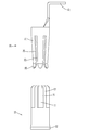
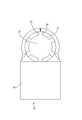
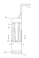
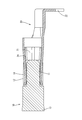
- FIG. CC The front view which shows the state before the fitting of the male terminal and female terminal in embodiment Right side view in FIG. CC sectional view in FIG.
- the figure which displayed only the female terminal in FIG. The figure which displayed only the male terminal in FIG.
- the female terminal 20 is obtained by bending a metal plate material such as copper or copper alloy punched into a predetermined shape. Further, the entire surface of the female terminal 20 is plated with tin or the like. As shown in FIG. 1, the female terminal 20 includes an elastic contact piece 21 and a wire crimping portion 22.
- each elastic contact piece 21 of the female terminal 20 is arranged at equal intervals in the circumferential direction.
- Each elastic contact piece 21 is paired with the opposing elastic contact piece 21.
- the inner region surrounded by each elastic contact piece 21 is a cavity 23 as shown in FIG.
- a terminal contact portion 11 of the male terminal 10 described later is inserted into the hollow portion 23.
- each elastic contact piece 21 inclines slightly toward radial inside. Thereby, the terminal contact portion 11 of the male terminal 10 is elastically pressed against the elastic contact piece 21 when the male terminal 10 and the female terminal 20 are fitted. Further, the distal end portion 26 of the elastic contact piece 21 is slightly bent outward in the radial direction so that a terminal contact portion 11 of the male terminal 10 described later can be easily inserted.
- the male terminal 10 is formed by using a round bar made of metal such as copper or copper alloy as a raw material, and forging or cutting the round bar. Further, the entire surface of the male terminal 10 is plated with tin or the like. As shown in FIG. 1, the male terminal 10 includes a terminal contact portion 11, a wire crimping portion 13, and a plurality of protrusions 12 that protrude outward from the outer peripheral surface of the terminal contact portion 11.
- the terminal contact portion 11 of the male terminal 10 is processed into a pin shape extending in the fitting direction with the female terminal 20. Furthermore, the some projection part 12 is formed by cutting the outer peripheral surface.
- the inner diameter R ⁇ b> 3 of the terminal contact portion 11 is processed to be larger than the minimum diameter R ⁇ b> 1 between the inner surfaces of the pair of elastic contact pieces 21 and smaller than the inner diameter R ⁇ b> 2 of the inner surfaces of the pair of elastic contact pieces 21.
- the outer diameter R4 of the pair of protrusions 12 is processed to be larger than the inner diameter R3 of the terminal contact portion 11.
- protrusions 12 are arranged at equal intervals in the circumferential direction.
- the number of protrusions 12 is the same as the number of elastic contact pieces 21.
- the protrusion 12 is a protrusion that fits in a space 25 between the side edges 24 of a pair of adjacent elastic contact pieces 21 as shown in FIG. 4 when the male terminal 10 and the female terminal 20 described later are fitted.
- the side edge 14 of the part 12 is processed so as to contact the side edge 24 of the elastic contact piece 21.
- the electric wire crimping portion 13 of the male terminal 10 is crimped to an electric wire (not shown). Thereby, the male terminal 10 and the electric wire are electrically connected.
- the protrusion 12 of the male terminal 10 is placed in the space 25 between the side edges 24 of the pair of adjacent elastic contact pieces 21 of the female terminal 20. It is in the form of entering. Therefore, for example, even if the male terminal 10 tries to twist by applying vibration from the outside to an electric wire (not shown) attached to the electric wire crimping portion 13 of the male terminal 10, the protruding portion 12 is formed between the adjacent elastic contact pieces 21. It will hit the side edge 24. Thereby, twisting of the male terminal 10 can be prevented.
- the terminal contact portion 11 of the male terminal 10 is elastically pressed by the elastic contact piece 21 of the female terminal 20 as shown in FIG. As a result, the male terminal 10 and the female terminal 20 come into contact with each other and are electrically connected.
- the side edge 14 of the protrusion 12 of the male terminal 10 is in contact with the side edge 24 of the adjacent elastic contact piece 21 of the female terminal 20. Therefore, the contact area between the male terminal 10 and the female terminal 20 increases. Thereby, the contact resistance between the male terminal 10 and the female terminal 20 can be reduced.
- one protrusion 12 of the male terminal 10 is stored in each space 25 of the female terminal 20.
- each protrusion 12 of the male terminal 10 contacts the side edge 24 of each elastic contact piece 21 of the female terminal 20. Therefore, the load applied to the elastic contact piece 21 when the protrusion 12 hits the elastic contact piece 21 by twisting of the male terminal 10 is distributed to each elastic contact piece 21. Thereby, the load concerning one elastic contact piece 21 by the twist of the male terminal 10 can be reduced.
- the male terminal 10 when the male terminal 10 and the female terminal 20 are fitted, the male terminal 10 is placed in the space 25 between the side edges 24 of the pair of elastic contact pieces 21 of the female terminal 20.
- the protruding portion 12 enters. Then, even if the male terminal 10 is twisted, the protrusion 12 of the male terminal 10 abuts the side edge 24 of the elastic contact piece 21 of the female terminal 20, so that the male terminal 10 can be prevented from being twisted.
- the protrusion 12 contacts the side edge 24 of the adjacent elastic contact piece 21 when the male terminal 10 and the female terminal 20 are fitted, so that the male terminal 10 and the female terminal 20 are in contact with each other when fitted. Therefore, the contact resistance between the male terminal 10 and the female terminal 20 can be further reduced.
- the protrusion 12 of the male terminal 10 is accommodated between all the adjacent elastic contact pieces 21 of the female terminal 20.
- the load applied to the elastic contact piece 21 when the projection 12 hits the elastic contact piece 21 by twisting of the male terminal 10 is distributed to each elastic contact piece 21. Therefore, the load applied to one elastic contact piece 21 of the female terminal 20 due to the twisting of the male terminal 10 can be reduced.
- the number of the protrusions 12 is the same as the number of the elastic contact pieces 21, but it may be smaller or larger.
- the number of the side edges 24 of the elastic contact piece 21 of the female terminal 20 is six in the protrusion 12 of the male terminal 10 in the above embodiment, the number may be any number.
- the protrusion 12 of the male terminal 10 is in contact with the side edge 24 of the adjacent elastic contact piece 21 of the female terminal 20, but may not be in contact.
- one protrusion 12 of the male terminal 10 is stored in the space 25 of the female terminal 20, but one or more protrusions 12 may or may not be stored. good.
Landscapes
- Connections Effected By Soldering, Adhesion, Or Permanent Deformation (AREA)
- Connector Housings Or Holding Contact Members (AREA)
Priority Applications (3)
| Application Number | Priority Date | Filing Date | Title |
|---|---|---|---|
| US16/491,637 US10847914B2 (en) | 2017-03-08 | 2018-02-21 | Male terminal |
| CN201880015963.5A CN110383590B (zh) | 2017-03-08 | 2018-02-21 | 阳端子 |
| DE112018001218.2T DE112018001218T5 (de) | 2017-03-08 | 2018-02-21 | Steckeranschluss |
Applications Claiming Priority (2)
| Application Number | Priority Date | Filing Date | Title |
|---|---|---|---|
| JP2017044016A JP6760142B2 (ja) | 2017-03-08 | 2017-03-08 | 雄端子 |
| JP2017-044016 | 2017-03-08 |
Publications (1)
| Publication Number | Publication Date |
|---|---|
| WO2018163814A1 true WO2018163814A1 (ja) | 2018-09-13 |
Family
ID=63448310
Family Applications (1)
| Application Number | Title | Priority Date | Filing Date |
|---|---|---|---|
| PCT/JP2018/006119 Ceased WO2018163814A1 (ja) | 2017-03-08 | 2018-02-21 | 雄端子 |
Country Status (5)
| Country | Link |
|---|---|
| US (1) | US10847914B2 (https=) |
| JP (1) | JP6760142B2 (https=) |
| CN (1) | CN110383590B (https=) |
| DE (1) | DE112018001218T5 (https=) |
| WO (1) | WO2018163814A1 (https=) |
Families Citing this family (5)
| Publication number | Priority date | Publication date | Assignee | Title |
|---|---|---|---|---|
| CN111193126A (zh) * | 2018-11-14 | 2020-05-22 | 泰科电子(上海)有限公司 | 导电端子和电连接器 |
| US11108181B2 (en) * | 2018-11-27 | 2021-08-31 | Carlisle Interconnect Technologies, Inc. | Vibration resistant high-power electrical connector |
| CN110190443B (zh) * | 2018-11-30 | 2021-11-16 | 中航光电科技股份有限公司 | 一种接触件及高速连接器 |
| WO2023004418A1 (en) | 2021-07-23 | 2023-01-26 | Carlisle Interconnect Technologies, Inc. | Electrical coax contact system |
| WO2023019146A1 (en) | 2021-08-10 | 2023-02-16 | Carlisle Interconnect Technologies, Inc. | High power electrical connector |
Citations (6)
| Publication number | Priority date | Publication date | Assignee | Title |
|---|---|---|---|---|
| JPH028880U (https=) * | 1988-07-01 | 1990-01-19 | ||
| JPH03214574A (ja) * | 1990-01-18 | 1991-09-19 | Fujitsu Ltd | コネクタの接続機構 |
| US20130210292A1 (en) * | 2010-08-19 | 2013-08-15 | Fci Automotive Holding | Electrical power terminal |
| JP2014107079A (ja) * | 2012-11-27 | 2014-06-09 | Auto Network Gijutsu Kenkyusho:Kk | 多接点型雌端子 |
| JP2015002072A (ja) * | 2013-06-14 | 2015-01-05 | 矢崎総業株式会社 | 端子構造 |
| JP2015222621A (ja) * | 2014-05-22 | 2015-12-10 | 株式会社オートネットワーク技術研究所 | 端子の接続構造 |
Family Cites Families (21)
| Publication number | Priority date | Publication date | Assignee | Title |
|---|---|---|---|---|
| US1552262A (en) * | 1923-11-08 | 1925-09-01 | Betz Charles Frederick | Electric-conductor coupling |
| US3670294A (en) * | 1970-10-19 | 1972-06-13 | Sylvania Electric Prod | Multiple contact electrical connector |
| US4278313A (en) * | 1979-09-12 | 1981-07-14 | The Bendix Corporation | Electrical contact with locking device |
| US4904554A (en) | 1988-03-21 | 1990-02-27 | Hughes Aircraft Company | Gas phase hardening of gelatin holograms |
| US4878861A (en) * | 1988-11-01 | 1989-11-07 | Elfab Corporation | Compliant electrical connector pin |
| FR2707806B1 (fr) * | 1993-07-12 | 1995-09-29 | Fels Const Electr | Dispositif de connexion modulaire à grand débattement. |
| JP3843514B2 (ja) * | 1995-12-15 | 2006-11-08 | イビデン株式会社 | 電子部品搭載用基板及びその製造方法 |
| US5897401A (en) * | 1997-07-01 | 1999-04-27 | Solid State Stamping, Inc. | Serrated starred pin |
| US6042429A (en) * | 1997-08-18 | 2000-03-28 | Autosplice Systems Inc. | Continuous press-fit knurl pin |
| CN2809940Y (zh) * | 2005-07-05 | 2006-08-23 | 建通精密工业股份有限公司 | 导电端子与内架结合的构造 |
| US20090170381A1 (en) * | 2006-05-16 | 2009-07-02 | Christopher Sommovigo | Electrical Connector Structure |
| US9270043B2 (en) * | 2012-03-16 | 2016-02-23 | Nhk Spring Co., Ltd. | Connector |
| JP5965811B2 (ja) * | 2012-10-03 | 2016-08-10 | 矢崎総業株式会社 | コネクタ |
| US9293850B2 (en) * | 2013-07-30 | 2016-03-22 | Hubbell Incorporated (Delaware) | High power electrical connector contact |
| JP2015082453A (ja) | 2013-10-24 | 2015-04-27 | 矢崎総業株式会社 | 端子 |
| CN203967307U (zh) * | 2014-07-18 | 2014-11-26 | 杭州龙洞电子有限公司 | 一种带有加强筋的插接件 |
| US9570832B2 (en) * | 2015-03-19 | 2017-02-14 | Semiconductor Components Industries, Llc | Press-fit pin for semiconductor packages and related methods |
| JP6550890B2 (ja) * | 2015-04-22 | 2019-07-31 | 住友電装株式会社 | プレスフィット端子 |
| JP5900685B1 (ja) * | 2015-04-30 | 2016-04-06 | 第一精工株式会社 | コネクタ端子 |
| US9595782B2 (en) * | 2015-08-05 | 2017-03-14 | Te Connectivity Corporation | Pin with angled retention member |
| US11108181B2 (en) * | 2018-11-27 | 2021-08-31 | Carlisle Interconnect Technologies, Inc. | Vibration resistant high-power electrical connector |
-
2017
- 2017-03-08 JP JP2017044016A patent/JP6760142B2/ja active Active
-
2018
- 2018-02-21 CN CN201880015963.5A patent/CN110383590B/zh active Active
- 2018-02-21 DE DE112018001218.2T patent/DE112018001218T5/de active Granted
- 2018-02-21 WO PCT/JP2018/006119 patent/WO2018163814A1/ja not_active Ceased
- 2018-02-21 US US16/491,637 patent/US10847914B2/en active Active
Patent Citations (6)
| Publication number | Priority date | Publication date | Assignee | Title |
|---|---|---|---|---|
| JPH028880U (https=) * | 1988-07-01 | 1990-01-19 | ||
| JPH03214574A (ja) * | 1990-01-18 | 1991-09-19 | Fujitsu Ltd | コネクタの接続機構 |
| US20130210292A1 (en) * | 2010-08-19 | 2013-08-15 | Fci Automotive Holding | Electrical power terminal |
| JP2014107079A (ja) * | 2012-11-27 | 2014-06-09 | Auto Network Gijutsu Kenkyusho:Kk | 多接点型雌端子 |
| JP2015002072A (ja) * | 2013-06-14 | 2015-01-05 | 矢崎総業株式会社 | 端子構造 |
| JP2015222621A (ja) * | 2014-05-22 | 2015-12-10 | 株式会社オートネットワーク技術研究所 | 端子の接続構造 |
Also Published As
| Publication number | Publication date |
|---|---|
| CN110383590B (zh) | 2021-01-26 |
| US10847914B2 (en) | 2020-11-24 |
| JP2018147822A (ja) | 2018-09-20 |
| CN110383590A (zh) | 2019-10-25 |
| US20200036126A1 (en) | 2020-01-30 |
| DE112018001218T5 (de) | 2019-11-21 |
| JP6760142B2 (ja) | 2020-09-23 |
Similar Documents
| Publication | Publication Date | Title |
|---|---|---|
| US8851940B2 (en) | Multi-piece socket contact assembly | |
| WO2018163814A1 (ja) | 雄端子 | |
| JP5995062B2 (ja) | ソケット端子 | |
| JP2015207540A (ja) | ソケットコンタクト | |
| JP5579212B2 (ja) | コネクタ端子用接触ばね及び雌端子、雄端子、コネクタ | |
| JP2018147828A (ja) | 圧着接続端子及び該圧着接続端子の接続方法 | |
| JP6888670B2 (ja) | 板ばね、接続端子台 | |
| JP7102134B2 (ja) | コネクタ | |
| JP2017010703A (ja) | 端子及び端子接続構造 | |
| JP6543553B2 (ja) | 端子及びその製造方法 | |
| JP2015090739A (ja) | 圧着端子 | |
| JP2013051136A (ja) | 接続端子 | |
| WO2015029731A1 (ja) | コネクタ | |
| KR101533808B1 (ko) | 커넥터 | |
| JP6796619B2 (ja) | 電線と端子の接続構造 | |
| TWI651905B (zh) | 電線用連接器 | |
| JP2015207353A (ja) | 電線用コネクタ | |
| JP6569140B2 (ja) | 雌端子金具 | |
| DK3123566T3 (en) | Contact socket for a socket or connector | |
| JP2009170331A (ja) | 接続端子 | |
| TWM608271U (zh) | 電連接器 | |
| TWI627797B (zh) | 電連接頭 | |
| US9608370B1 (en) | Connector terminal | |
| JP5074270B2 (ja) | 端子金具及びワイヤーハーネス | |
| JP6301722B2 (ja) | 接点接続構造 |
Legal Events
| Date | Code | Title | Description |
|---|---|---|---|
| 121 | Ep: the epo has been informed by wipo that ep was designated in this application |
Ref document number: 18763542 Country of ref document: EP Kind code of ref document: A1 |
|
| 122 | Ep: pct application non-entry in european phase |
Ref document number: 18763542 Country of ref document: EP Kind code of ref document: A1 |