WO2018163814A1 - Male terminal - Google Patents
Male terminal Download PDFInfo
- Publication number
- WO2018163814A1 WO2018163814A1 PCT/JP2018/006119 JP2018006119W WO2018163814A1 WO 2018163814 A1 WO2018163814 A1 WO 2018163814A1 JP 2018006119 W JP2018006119 W JP 2018006119W WO 2018163814 A1 WO2018163814 A1 WO 2018163814A1
- Authority
- WO
- WIPO (PCT)
- Prior art keywords
- terminal
- male terminal
- elastic contact
- female terminal
- male
- Prior art date
Links
Images


Classifications
-
- H—ELECTRICITY
- H01—ELECTRIC ELEMENTS
- H01R—ELECTRICALLY-CONDUCTIVE CONNECTIONS; STRUCTURAL ASSOCIATIONS OF A PLURALITY OF MUTUALLY-INSULATED ELECTRICAL CONNECTING ELEMENTS; COUPLING DEVICES; CURRENT COLLECTORS
- H01R13/00—Details of coupling devices of the kinds covered by groups H01R12/70 or H01R24/00 - H01R33/00
- H01R13/02—Contact members
- H01R13/04—Pins or blades for co-operation with sockets
-
- H—ELECTRICITY
- H01—ELECTRIC ELEMENTS
- H01R—ELECTRICALLY-CONDUCTIVE CONNECTIONS; STRUCTURAL ASSOCIATIONS OF A PLURALITY OF MUTUALLY-INSULATED ELECTRICAL CONNECTING ELEMENTS; COUPLING DEVICES; CURRENT COLLECTORS
- H01R13/00—Details of coupling devices of the kinds covered by groups H01R12/70 or H01R24/00 - H01R33/00
- H01R13/02—Contact members
- H01R13/10—Sockets for co-operation with pins or blades
- H01R13/11—Resilient sockets
-
- H—ELECTRICITY
- H01—ELECTRIC ELEMENTS
- H01R—ELECTRICALLY-CONDUCTIVE CONNECTIONS; STRUCTURAL ASSOCIATIONS OF A PLURALITY OF MUTUALLY-INSULATED ELECTRICAL CONNECTING ELEMENTS; COUPLING DEVICES; CURRENT COLLECTORS
- H01R13/00—Details of coupling devices of the kinds covered by groups H01R12/70 or H01R24/00 - H01R33/00
- H01R13/02—Contact members
- H01R13/20—Pins, blades, or sockets shaped, or provided with separate member, to retain co-operating parts together
-
- H—ELECTRICITY
- H01—ELECTRIC ELEMENTS
- H01R—ELECTRICALLY-CONDUCTIVE CONNECTIONS; STRUCTURAL ASSOCIATIONS OF A PLURALITY OF MUTUALLY-INSULATED ELECTRICAL CONNECTING ELEMENTS; COUPLING DEVICES; CURRENT COLLECTORS
- H01R4/00—Electrically-conductive connections between two or more conductive members in direct contact, i.e. touching one another; Means for effecting or maintaining such contact; Electrically-conductive connections having two or more spaced connecting locations for conductors and using contact members penetrating insulation
- H01R4/10—Electrically-conductive connections between two or more conductive members in direct contact, i.e. touching one another; Means for effecting or maintaining such contact; Electrically-conductive connections having two or more spaced connecting locations for conductors and using contact members penetrating insulation effected solely by twisting, wrapping, bending, crimping, or other permanent deformation
- H01R4/12—Electrically-conductive connections between two or more conductive members in direct contact, i.e. touching one another; Means for effecting or maintaining such contact; Electrically-conductive connections having two or more spaced connecting locations for conductors and using contact members penetrating insulation effected solely by twisting, wrapping, bending, crimping, or other permanent deformation by twisting
-
- H—ELECTRICITY
- H01—ELECTRIC ELEMENTS
- H01R—ELECTRICALLY-CONDUCTIVE CONNECTIONS; STRUCTURAL ASSOCIATIONS OF A PLURALITY OF MUTUALLY-INSULATED ELECTRICAL CONNECTING ELEMENTS; COUPLING DEVICES; CURRENT COLLECTORS
- H01R13/00—Details of coupling devices of the kinds covered by groups H01R12/70 or H01R24/00 - H01R33/00
- H01R13/02—Contact members
- H01R13/10—Sockets for co-operation with pins or blades
- H01R13/11—Resilient sockets
- H01R13/111—Resilient sockets co-operating with pins having a circular transverse section
Definitions
- the technology disclosed in this specification relates to a male terminal.
- a male terminal described in JP-A-2015-82453 (the following Patent Document 1) is known.
- This male terminal has a pin-shaped insertion portion that is inserted into the box-shaped portion of the female terminal, and a wire crimping portion that is crimped to the core wire exposed by peeling off the sheath of the wire.
- the female terminal to which the male terminal is connected has a pair of elastic pieces provided at the front end portion of the terminal and a wire crimping portion provided at the terminal rear end portion and crimped to the electric wire.
- the male terminal disclosed in the present specification is a male terminal that can be fitted to a female terminal including at least a pair of elastic contact pieces, has a pin shape, and is fitted with the female terminal when the female terminal is fitted.
- the protrusion may be configured to contact the elastic contact piece when fitted with the female terminal. According to such a configuration, the contact area between the male terminal and the female terminal when fitted is increased, and therefore the contact resistance between the male terminal and the female terminal can be further reduced.
- the number of the protrusions may be the same as the number of the elastic contact pieces, and one protrusion may be housed between the side edges of the pair of adjacent elastic contact pieces.
- the protrusion part of a male terminal will be accommodated between all the adjacent elastic contact pieces of a female terminal. Thereby, the load applied to the elastic contact piece when the protrusion hits the elastic contact piece by twisting the male terminal is distributed to each elastic contact piece. Therefore, the load applied to one elastic contact piece of the female terminal due to the twisting of the male terminal can be reduced.
- the male terminal can be prevented from being twisted.
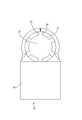
- FIG. CC The front view which shows the state before the fitting of the male terminal and female terminal in embodiment Right side view in FIG. CC sectional view in FIG.
- the figure which displayed only the female terminal in FIG. The figure which displayed only the male terminal in FIG.
- the female terminal 20 is obtained by bending a metal plate material such as copper or copper alloy punched into a predetermined shape. Further, the entire surface of the female terminal 20 is plated with tin or the like. As shown in FIG. 1, the female terminal 20 includes an elastic contact piece 21 and a wire crimping portion 22.
- each elastic contact piece 21 of the female terminal 20 is arranged at equal intervals in the circumferential direction.
- Each elastic contact piece 21 is paired with the opposing elastic contact piece 21.
- the inner region surrounded by each elastic contact piece 21 is a cavity 23 as shown in FIG.
- a terminal contact portion 11 of the male terminal 10 described later is inserted into the hollow portion 23.
- each elastic contact piece 21 inclines slightly toward radial inside. Thereby, the terminal contact portion 11 of the male terminal 10 is elastically pressed against the elastic contact piece 21 when the male terminal 10 and the female terminal 20 are fitted. Further, the distal end portion 26 of the elastic contact piece 21 is slightly bent outward in the radial direction so that a terminal contact portion 11 of the male terminal 10 described later can be easily inserted.
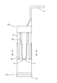
- the male terminal 10 is formed by using a round bar made of metal such as copper or copper alloy as a raw material, and forging or cutting the round bar. Further, the entire surface of the male terminal 10 is plated with tin or the like. As shown in FIG. 1, the male terminal 10 includes a terminal contact portion 11, a wire crimping portion 13, and a plurality of protrusions 12 that protrude outward from the outer peripheral surface of the terminal contact portion 11.
- the terminal contact portion 11 of the male terminal 10 is processed into a pin shape extending in the fitting direction with the female terminal 20. Furthermore, the some projection part 12 is formed by cutting the outer peripheral surface.
- the inner diameter R ⁇ b> 3 of the terminal contact portion 11 is processed to be larger than the minimum diameter R ⁇ b> 1 between the inner surfaces of the pair of elastic contact pieces 21 and smaller than the inner diameter R ⁇ b> 2 of the inner surfaces of the pair of elastic contact pieces 21.
- the outer diameter R4 of the pair of protrusions 12 is processed to be larger than the inner diameter R3 of the terminal contact portion 11.
- protrusions 12 are arranged at equal intervals in the circumferential direction.
- the number of protrusions 12 is the same as the number of elastic contact pieces 21.
- the protrusion 12 is a protrusion that fits in a space 25 between the side edges 24 of a pair of adjacent elastic contact pieces 21 as shown in FIG. 4 when the male terminal 10 and the female terminal 20 described later are fitted.
- the side edge 14 of the part 12 is processed so as to contact the side edge 24 of the elastic contact piece 21.
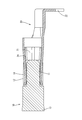
- the electric wire crimping portion 13 of the male terminal 10 is crimped to an electric wire (not shown). Thereby, the male terminal 10 and the electric wire are electrically connected.
- the protrusion 12 of the male terminal 10 is placed in the space 25 between the side edges 24 of the pair of adjacent elastic contact pieces 21 of the female terminal 20. It is in the form of entering. Therefore, for example, even if the male terminal 10 tries to twist by applying vibration from the outside to an electric wire (not shown) attached to the electric wire crimping portion 13 of the male terminal 10, the protruding portion 12 is formed between the adjacent elastic contact pieces 21. It will hit the side edge 24. Thereby, twisting of the male terminal 10 can be prevented.
- the terminal contact portion 11 of the male terminal 10 is elastically pressed by the elastic contact piece 21 of the female terminal 20 as shown in FIG. As a result, the male terminal 10 and the female terminal 20 come into contact with each other and are electrically connected.
- the side edge 14 of the protrusion 12 of the male terminal 10 is in contact with the side edge 24 of the adjacent elastic contact piece 21 of the female terminal 20. Therefore, the contact area between the male terminal 10 and the female terminal 20 increases. Thereby, the contact resistance between the male terminal 10 and the female terminal 20 can be reduced.
- one protrusion 12 of the male terminal 10 is stored in each space 25 of the female terminal 20.
- each protrusion 12 of the male terminal 10 contacts the side edge 24 of each elastic contact piece 21 of the female terminal 20. Therefore, the load applied to the elastic contact piece 21 when the protrusion 12 hits the elastic contact piece 21 by twisting of the male terminal 10 is distributed to each elastic contact piece 21. Thereby, the load concerning one elastic contact piece 21 by the twist of the male terminal 10 can be reduced.
- the male terminal 10 when the male terminal 10 and the female terminal 20 are fitted, the male terminal 10 is placed in the space 25 between the side edges 24 of the pair of elastic contact pieces 21 of the female terminal 20.
- the protruding portion 12 enters. Then, even if the male terminal 10 is twisted, the protrusion 12 of the male terminal 10 abuts the side edge 24 of the elastic contact piece 21 of the female terminal 20, so that the male terminal 10 can be prevented from being twisted.
- the protrusion 12 contacts the side edge 24 of the adjacent elastic contact piece 21 when the male terminal 10 and the female terminal 20 are fitted, so that the male terminal 10 and the female terminal 20 are in contact with each other when fitted. Therefore, the contact resistance between the male terminal 10 and the female terminal 20 can be further reduced.
- the protrusion 12 of the male terminal 10 is accommodated between all the adjacent elastic contact pieces 21 of the female terminal 20.
- the load applied to the elastic contact piece 21 when the projection 12 hits the elastic contact piece 21 by twisting of the male terminal 10 is distributed to each elastic contact piece 21. Therefore, the load applied to one elastic contact piece 21 of the female terminal 20 due to the twisting of the male terminal 10 can be reduced.
- the number of the protrusions 12 is the same as the number of the elastic contact pieces 21, but it may be smaller or larger.
- the number of the side edges 24 of the elastic contact piece 21 of the female terminal 20 is six in the protrusion 12 of the male terminal 10 in the above embodiment, the number may be any number.
- the protrusion 12 of the male terminal 10 is in contact with the side edge 24 of the adjacent elastic contact piece 21 of the female terminal 20, but may not be in contact.
- one protrusion 12 of the male terminal 10 is stored in the space 25 of the female terminal 20, but one or more protrusions 12 may or may not be stored. good.
Abstract
A male terminal disclosed herein is a male terminal 10 that can be fitted into a female terminal 20 which is provided with at least a pair of elastic contact pieces. This male terminal 10 is provided with: a terminal contact part 11 which has a pin shape and comes into contact with elastic contact pieces 21 of the female terminal 20 when the male terminal 10 is fitted into the female terminal 20; and a protrusion part 12 which is provided to protrude from an outer peripheral surface of the terminal contact part 11 and arranged so as to be accommodated between side edges 24 of a pair of adjacent elastic contact pieces 21 of the female terminal 20 when the male terminal 10 is fitted into the female terminal 20.
Description
本明細書によって開示される技術は、雄端子に関する。
The technology disclosed in this specification relates to a male terminal.
従来、雄端子の一例として、特開2015-82453号(下記特許文献1)に記載のオス端子が知られている。このオス端子は、メス端子の箱状部内に挿入されるピン状の挿入部と、電線のシースが剥かれて露出した芯線に圧着される電線圧着部とを有している。一方、オス端子が接続されるメス端子は、端子前端部に設けられた一対の弾性片と、端子後端部に設けられ電線に圧着される電線圧着部とを有している。オス端子の挿入部をメス端子の箱状部内に挿入すると、オス端子の挿入部は、メス端子の一対の弾性接触片に抑えつけられて接触し、オスメス両端子が電気的に導通する。
Conventionally, as an example of a male terminal, a male terminal described in JP-A-2015-82453 (the following Patent Document 1) is known. This male terminal has a pin-shaped insertion portion that is inserted into the box-shaped portion of the female terminal, and a wire crimping portion that is crimped to the core wire exposed by peeling off the sheath of the wire. On the other hand, the female terminal to which the male terminal is connected has a pair of elastic pieces provided at the front end portion of the terminal and a wire crimping portion provided at the terminal rear end portion and crimped to the electric wire. When the insertion portion of the male terminal is inserted into the box-shaped portion of the female terminal, the insertion portion of the male terminal is pressed against and brought into contact with the pair of elastic contact pieces of the female terminal, and the male and female terminals are electrically connected.
ところで、このような構成とすると、例えばオス端子又はメス端子に圧着された電線に振動が加わると、オス端子が捻回することにより端子接点の摺動が起こり、摩耗することで、接点不良に繋がることが懸念される。また、オス端子の捻回を抑えるため、メス端子の接圧を上げると、オス端子の挿入力を強くしなければならず、オス端子挿入の作業性悪化が懸念される。
By the way, with such a configuration, for example, when vibration is applied to an electric wire crimped to a male terminal or a female terminal, the terminal contact slides due to twisting of the male terminal and wears, resulting in a contact failure. There is concern about being connected. Further, if the contact pressure of the female terminal is increased in order to suppress the twisting of the male terminal, the insertion force of the male terminal must be increased, and there is a concern that the workability of the male terminal insertion is deteriorated.
本明細書に開示される雄端子は、少なくとも一対の弾性接触片を備える雌端子と嵌合可能な雄端子であって、ピン形状をなし、前記雌端子との嵌合時に前記雌端子の前記弾性接触片と接触する端子接触部と、前記端子接触部の外周面から突出して設けられ、前記雌端子との嵌合時に、前記雌端子の隣り合う一対の前記弾性接触片の側縁の間に収まるように配置された突起部とを備えている。
このような構成にすると、雄端子と雌端子が嵌合されると、雌端子の少なくとも一対の弾性接触片の側縁の間に、雄端子の突起部が入り込む。すると、雄端子が捻回しても、雄端子の突起部が雌端子の弾性接触片の側縁と当たるため、雄端子の捻回を防止することができる。 The male terminal disclosed in the present specification is a male terminal that can be fitted to a female terminal including at least a pair of elastic contact pieces, has a pin shape, and is fitted with the female terminal when the female terminal is fitted. A terminal contact portion that comes into contact with the elastic contact piece, and is provided so as to protrude from the outer peripheral surface of the terminal contact portion, and between the side edges of the pair of adjacent elastic contact pieces of the female terminal when fitted to the female terminal And a projecting portion arranged so as to fit in the housing.
With such a configuration, when the male terminal and the female terminal are fitted, the protruding portion of the male terminal enters between the side edges of at least the pair of elastic contact pieces of the female terminal. Then, even if the male terminal is twisted, the male terminal can be prevented from being twisted because the protruding portion of the male terminal hits the side edge of the elastic contact piece of the female terminal.
本明細書に開示される雄端子の実施の態様として、前記突起部は、前記雌端子との嵌合時、前記弾性接触片と接触する構成としても良い。
このような構成によると、雄端子と雌端子が嵌合時に接触する面積が増えるため、雄端子と雌端子との間の接触抵抗をより低くすることができる。 As an embodiment of the male terminal disclosed in the present specification, the protrusion may be configured to contact the elastic contact piece when fitted with the female terminal.
According to such a configuration, the contact area between the male terminal and the female terminal when fitted is increased, and therefore the contact resistance between the male terminal and the female terminal can be further reduced.
また、前記突起部は、前記弾性接触片の数と同数であり、かつ隣り合う一対の前記弾性接触片の側縁の間に1つずつ収められている構成としても良い。
このような構成によると、雌端子のそれぞれの弾性接触片の隣り合う全ての間に、雄端子の突起部が収められることとなる。それにより、雄端子の捻回によって突起部が弾性接触片に当たった際に弾性接触片に加わる負荷は、それぞれの弾性接触片に分散される。従って、雄端子の捻回により雌端子の一つの弾性接触片に加わる負荷を低減させることができる。 Further, the number of the protrusions may be the same as the number of the elastic contact pieces, and one protrusion may be housed between the side edges of the pair of adjacent elastic contact pieces.
According to such a structure, the protrusion part of a male terminal will be accommodated between all the adjacent elastic contact pieces of a female terminal. Thereby, the load applied to the elastic contact piece when the protrusion hits the elastic contact piece by twisting the male terminal is distributed to each elastic contact piece. Therefore, the load applied to one elastic contact piece of the female terminal due to the twisting of the male terminal can be reduced.
本明細書に開示される雄端子によれば、雄端子の捻回を防止することができる。
According to the male terminal disclosed in this specification, the male terminal can be prevented from being twisted.
<実施形態>
実施形態を、図1から図8を参照しつつ説明する。
雌端子20は、所定の形状に打ち抜かれた銅、銅合金等の金属板材を曲げ加工したものである。さらに雌端子20の表面全体には錫等のメッキ処理が施されている。雌端子20は、図1に示すように弾性接触片21と、電線圧着部22とからなる。 <Embodiment>
Embodiments will be described with reference to FIGS. 1 to 8.
Thefemale terminal 20 is obtained by bending a metal plate material such as copper or copper alloy punched into a predetermined shape. Further, the entire surface of the female terminal 20 is plated with tin or the like. As shown in FIG. 1, the female terminal 20 includes an elastic contact piece 21 and a wire crimping portion 22.
実施形態を、図1から図8を参照しつつ説明する。
雌端子20は、所定の形状に打ち抜かれた銅、銅合金等の金属板材を曲げ加工したものである。さらに雌端子20の表面全体には錫等のメッキ処理が施されている。雌端子20は、図1に示すように弾性接触片21と、電線圧着部22とからなる。 <Embodiment>
Embodiments will be described with reference to FIGS. 1 to 8.
The
雌端子20の弾性接触片21は、図2及び図4に示すように周方向に対して等間隔に6つ配置されている。それぞれの弾性接触片21は、向かい合った弾性接触片21と対をなしている。それぞれの弾性接触片21で囲まれた内部領域は、図4に示すように空洞部23となっている。この空洞部23に、後述する雄端子10の端子接触部11が挿通される。また、図1に示すように、それぞれの弾性接触片21は径方向内側に向けてやや傾斜している。これにより、雄端子10と雌端子20の嵌合時に、雄端子10の端子接触部11が弾性接触片21に弾性的に押さえつけられる。さらに弾性接触片21の先端部26は、後述する雄端子10の端子接触部11が挿入し易いように、径方向外側に向けてやや折り曲げられている。
As shown in FIGS. 2 and 4, six elastic contact pieces 21 of the female terminal 20 are arranged at equal intervals in the circumferential direction. Each elastic contact piece 21 is paired with the opposing elastic contact piece 21. The inner region surrounded by each elastic contact piece 21 is a cavity 23 as shown in FIG. A terminal contact portion 11 of the male terminal 10 described later is inserted into the hollow portion 23. Moreover, as shown in FIG. 1, each elastic contact piece 21 inclines slightly toward radial inside. Thereby, the terminal contact portion 11 of the male terminal 10 is elastically pressed against the elastic contact piece 21 when the male terminal 10 and the female terminal 20 are fitted. Further, the distal end portion 26 of the elastic contact piece 21 is slightly bent outward in the radial direction so that a terminal contact portion 11 of the male terminal 10 described later can be easily inserted.
雌端子20の電線圧着部22には、図示していない電線が圧着される。これにより、雌端子20と電線は電気的に導通する。
雄端子10は、銅、銅合金等の金属製の丸棒を素材とし、丸棒を圧造又は切削等して加工したものである。さらに雄端子10の表面全体には錫等のメッキ処理が施されている。雄端子10は、図1に示すように端子接触部11と、電線圧着部13と、さらに端子接触部11の外周面から外側に突出する複数の突起部12とからなる。 An electric wire (not shown) is crimped to the electricwire crimping portion 22 of the female terminal 20. Thereby, the female terminal 20 and the electric wire are electrically connected.
Themale terminal 10 is formed by using a round bar made of metal such as copper or copper alloy as a raw material, and forging or cutting the round bar. Further, the entire surface of the male terminal 10 is plated with tin or the like. As shown in FIG. 1, the male terminal 10 includes a terminal contact portion 11, a wire crimping portion 13, and a plurality of protrusions 12 that protrude outward from the outer peripheral surface of the terminal contact portion 11.
雄端子10は、銅、銅合金等の金属製の丸棒を素材とし、丸棒を圧造又は切削等して加工したものである。さらに雄端子10の表面全体には錫等のメッキ処理が施されている。雄端子10は、図1に示すように端子接触部11と、電線圧着部13と、さらに端子接触部11の外周面から外側に突出する複数の突起部12とからなる。 An electric wire (not shown) is crimped to the electric
The
雄端子10の端子接触部11は、図1に示すように、雌端子20との嵌合方向に対して伸びるピン状に加工されている。さらに、複数の突起部12が、その外周面を切削加工して形成されている。
As shown in FIG. 1, the terminal contact portion 11 of the male terminal 10 is processed into a pin shape extending in the fitting direction with the female terminal 20. Furthermore, the some projection part 12 is formed by cutting the outer peripheral surface.
図3に示すように、端子接触部11の内径R3は、一対の弾性接触片21の内面間の最小径R1よりも大きく、かつ一対の弾性接触片21の内面入口の径R2よりも小さく加工されている。また、一対の突起部12の外径R4は、端子接触部11の内径R3よりも大きく加工されている。
As shown in FIG. 3, the inner diameter R <b> 3 of the terminal contact portion 11 is processed to be larger than the minimum diameter R <b> 1 between the inner surfaces of the pair of elastic contact pieces 21 and smaller than the inner diameter R <b> 2 of the inner surfaces of the pair of elastic contact pieces 21. Has been. Further, the outer diameter R4 of the pair of protrusions 12 is processed to be larger than the inner diameter R3 of the terminal contact portion 11.
突起部12は、図2、図5に示すように周方向に対して等間隔に6つ配置されている。突起部12の数は、弾性接触片21の数と同数となっている。突起部12は、後述する雄端子10と雌端子20の嵌合時に、図4に示すように隣り合う一対の弾性接触片21の側縁24の間の空間25に収まるように、かつ、突起部12の側縁14が弾性接触片21の側縁24に接触するように加工されている。
As shown in FIGS. 2 and 5, six protrusions 12 are arranged at equal intervals in the circumferential direction. The number of protrusions 12 is the same as the number of elastic contact pieces 21. The protrusion 12 is a protrusion that fits in a space 25 between the side edges 24 of a pair of adjacent elastic contact pieces 21 as shown in FIG. 4 when the male terminal 10 and the female terminal 20 described later are fitted. The side edge 14 of the part 12 is processed so as to contact the side edge 24 of the elastic contact piece 21.
雄端子10の電線圧着部13は、図示しない電線に圧着される。これにより、雄端子10と電線は電気的に導通する。
The electric wire crimping portion 13 of the male terminal 10 is crimped to an electric wire (not shown). Thereby, the male terminal 10 and the electric wire are electrically connected.
次に、本実施形態の作用について説明する。
雄端子10と雌端子20を嵌合すると、図6に示すように、雄端子10の突起部12が、雌端子20の隣り合う一対の弾性接触片21の側縁24の間の空間25に入り込む形となっている。そのため、例えば雄端子10の電線圧着部13に取り付けられた図示しない電線に外部から振動が加えられることによって、雄端子10が捻回しようとしても、突起部12が、隣り合う弾性接触片21の側縁24に当たることとなる。これにより、雄端子10の捻回を防止することができる。 Next, the operation of this embodiment will be described.
When themale terminal 10 and the female terminal 20 are fitted, as shown in FIG. 6, the protrusion 12 of the male terminal 10 is placed in the space 25 between the side edges 24 of the pair of adjacent elastic contact pieces 21 of the female terminal 20. It is in the form of entering. Therefore, for example, even if the male terminal 10 tries to twist by applying vibration from the outside to an electric wire (not shown) attached to the electric wire crimping portion 13 of the male terminal 10, the protruding portion 12 is formed between the adjacent elastic contact pieces 21. It will hit the side edge 24. Thereby, twisting of the male terminal 10 can be prevented.
雄端子10と雌端子20を嵌合すると、図6に示すように、雄端子10の突起部12が、雌端子20の隣り合う一対の弾性接触片21の側縁24の間の空間25に入り込む形となっている。そのため、例えば雄端子10の電線圧着部13に取り付けられた図示しない電線に外部から振動が加えられることによって、雄端子10が捻回しようとしても、突起部12が、隣り合う弾性接触片21の側縁24に当たることとなる。これにより、雄端子10の捻回を防止することができる。 Next, the operation of this embodiment will be described.
When the
雄端子10と雌端子20を嵌合すると、図8に示すように、雄端子10の端子接触部11は、雌端子20の弾性接触片21に弾性的に押さえられる。これにより雄端子10と雌端子20は接触し、電気的に導通する。
When the male terminal 10 and the female terminal 20 are fitted, the terminal contact portion 11 of the male terminal 10 is elastically pressed by the elastic contact piece 21 of the female terminal 20 as shown in FIG. As a result, the male terminal 10 and the female terminal 20 come into contact with each other and are electrically connected.
さらに、図7に示すように、雄端子10の突起部12の側縁14は、雌端子20の隣り合う弾性接触片21の側縁24と接触している。そのため、雄端子10と雌端子20の接触面積は増加する。これにより、雄端子10と雌端子20間の接触抵抗を減らすことができる。
Furthermore, as shown in FIG. 7, the side edge 14 of the protrusion 12 of the male terminal 10 is in contact with the side edge 24 of the adjacent elastic contact piece 21 of the female terminal 20. Therefore, the contact area between the male terminal 10 and the female terminal 20 increases. Thereby, the contact resistance between the male terminal 10 and the female terminal 20 can be reduced.
また、図7に示すように、雌端子20の各空間25に、雄端子10の突起部12が1つずつ収められている。これにより、雄端子10が捻回した際に、雄端子10のそれぞれの突起部12が、雌端子20のそれぞれの弾性接触片21の側縁24に当たることとなる。そのため、雄端子10の捻回により突起部12が弾性接触片21に当たる際に弾性接触片21にかかる負荷は、それぞれの弾性接触片21に分散される。これにより、雄端子10の捻回による一つの弾性接触片21にかかる負荷を低減させることができる。
Further, as shown in FIG. 7, one protrusion 12 of the male terminal 10 is stored in each space 25 of the female terminal 20. Thereby, when the male terminal 10 is twisted, each protrusion 12 of the male terminal 10 contacts the side edge 24 of each elastic contact piece 21 of the female terminal 20. Therefore, the load applied to the elastic contact piece 21 when the protrusion 12 hits the elastic contact piece 21 by twisting of the male terminal 10 is distributed to each elastic contact piece 21. Thereby, the load concerning one elastic contact piece 21 by the twist of the male terminal 10 can be reduced.
以上のように本実施形態によれば、雄端子10と雌端子20が嵌合されると、雌端子20の少なくとも一対の弾性接触片21の側縁24の間の空間25に、雄端子10の突起部12が入り込む。すると、雄端子10が捻回しても、雄端子10の突起部12が雌端子20の弾性接触片21の側縁24と当たるため、雄端子10の捻回を防止することができる。
As described above, according to the present embodiment, when the male terminal 10 and the female terminal 20 are fitted, the male terminal 10 is placed in the space 25 between the side edges 24 of the pair of elastic contact pieces 21 of the female terminal 20. The protruding portion 12 enters. Then, even if the male terminal 10 is twisted, the protrusion 12 of the male terminal 10 abuts the side edge 24 of the elastic contact piece 21 of the female terminal 20, so that the male terminal 10 can be prevented from being twisted.
また、突起部12は、雄端子10と雌端子20との嵌合時、隣り合う弾性接触片21の側縁24と接触することにより、雄端子10と雌端子20が嵌合時に接触する面積が増えるため、雄端子10と雌端子20間の接触抵抗をより低くすることができる。
Moreover, the protrusion 12 contacts the side edge 24 of the adjacent elastic contact piece 21 when the male terminal 10 and the female terminal 20 are fitted, so that the male terminal 10 and the female terminal 20 are in contact with each other when fitted. Therefore, the contact resistance between the male terminal 10 and the female terminal 20 can be further reduced.
また、雌端子20のそれぞれの弾性接触片21の隣り合う全ての間に、雄端子10の突起部12が収められることとなる。それにより、雄端子10の捻回によって突起部12が弾性接触片21に当たった際に弾性接触片21に加わる負荷は、それぞれの弾性接触片21に分散される。従って、雄端子10の捻回により雌端子20の一つの弾性接触片21に加わる負荷を低減させることができる。
<他の実施形態>
本明細書によって開示される雄端子は、上記記述及び図面によって説明した実施形態に限定されるものではなく、例えば次のような種々の態様も含まれる。 Further, theprotrusion 12 of the male terminal 10 is accommodated between all the adjacent elastic contact pieces 21 of the female terminal 20. As a result, the load applied to the elastic contact piece 21 when the projection 12 hits the elastic contact piece 21 by twisting of the male terminal 10 is distributed to each elastic contact piece 21. Therefore, the load applied to one elastic contact piece 21 of the female terminal 20 due to the twisting of the male terminal 10 can be reduced.
<Other embodiments>
The male terminal disclosed by this specification is not limited to embodiment described with the said description and drawing, For example, the following various aspects are also included.
<他の実施形態>
本明細書によって開示される雄端子は、上記記述及び図面によって説明した実施形態に限定されるものではなく、例えば次のような種々の態様も含まれる。 Further, the
<Other embodiments>
The male terminal disclosed by this specification is not limited to embodiment described with the said description and drawing, For example, the following various aspects are also included.
(1)上記実施形態では、突起部12の数は弾性接触片21の数と同数としていたが、それより少なくても良く、又は多くても良い。
(1) In the above embodiment, the number of the protrusions 12 is the same as the number of the elastic contact pieces 21, but it may be smaller or larger.
(2)上記実施形態では、雄端子10の突起部12は、雌端子20の弾性接触片21の側縁24の数は6つとしていたが、数はいくつでも良い。
(2) Although the number of the side edges 24 of the elastic contact piece 21 of the female terminal 20 is six in the protrusion 12 of the male terminal 10 in the above embodiment, the number may be any number.
(3)上記実施形態では、雄端子10の突起部12は、雌端子20の隣り合う弾性接触片21の側縁24と接触させていたが、接触していなくても良い。
(3) In the above embodiment, the protrusion 12 of the male terminal 10 is in contact with the side edge 24 of the adjacent elastic contact piece 21 of the female terminal 20, but may not be in contact.
(4)上記実施形態では、雄端子10の突起部12は、雌端子20の空間25にそれぞれ1つずつ収められているとしていたが、1つ以上収めても良いし、又は収めなくても良い。
(4) In the above embodiment, one protrusion 12 of the male terminal 10 is stored in the space 25 of the female terminal 20, but one or more protrusions 12 may or may not be stored. good.
10…雄端子
11…端子接触部
12…突起部
13…電線圧着部
14…側縁
20…雌端子
21…弾性接触片
22…電線圧着部
24…側縁
26…先端部 DESCRIPTION OFSYMBOLS 10 ... Male terminal 11 ... Terminal contact part 12 ... Protrusion part 13 ... Wire crimping part 14 ... Side edge 20 ... Female terminal 21 ... Elastic contact piece 22 ... Electric wire crimping part 24 ... Side edge 26 ... Tip part
11…端子接触部
12…突起部
13…電線圧着部
14…側縁
20…雌端子
21…弾性接触片
22…電線圧着部
24…側縁
26…先端部 DESCRIPTION OF
Claims (3)
- 少なくとも一対の弾性接触片を備える雌端子と嵌合可能な雄端子であって、
ピン形状をなし、前記雌端子との嵌合時に前記雌端子の前記弾性接触片と接触する端子接触部と、
前記端子接触部の外周面から突出して設けられ、前記雌端子との嵌合時に、前記雌端子の隣り合う一対の前記弾性接触片の側縁の間に収まるように配置された突起部とを備える雄端子。 A male terminal that can be fitted to a female terminal provided with at least a pair of elastic contact pieces,
A pin contact shape, a terminal contact portion that contacts the elastic contact piece of the female terminal when fitted with the female terminal,
Protrusions provided so as to protrude from the outer peripheral surface of the terminal contact portion, and arranged so as to fit between the side edges of the pair of adjacent elastic contact pieces of the female terminal when fitted with the female terminal. Male terminal provided. - 前記突起部は、前記雌端子との嵌合時、前記弾性接触片と接触していることを特徴とする請求項1記載の雄端子。 The male terminal according to claim 1, wherein the protruding portion is in contact with the elastic contact piece when fitted with the female terminal.
- 前記突起部は、前記弾性接触片の数と同数であり、かつ隣り合う一対の前記弾性接触片の側縁の間に1つずつ収められていることを特徴とする請求項1又は請求項2記載の雄端子。 The number of the protrusions is the same as the number of the elastic contact pieces, and one protrusion is housed between the side edges of a pair of adjacent elastic contact pieces. Male terminal as described.
Priority Applications (3)
| Application Number | Priority Date | Filing Date | Title |
|---|---|---|---|
| DE112018001218.2T DE112018001218T5 (en) | 2017-03-08 | 2018-02-21 | connector |
| US16/491,637 US10847914B2 (en) | 2017-03-08 | 2018-02-21 | Male terminal |
| CN201880015963.5A CN110383590B (en) | 2017-03-08 | 2018-02-21 | Male terminal |
Applications Claiming Priority (2)
| Application Number | Priority Date | Filing Date | Title |
|---|---|---|---|
| JP2017044016A JP6760142B2 (en) | 2017-03-08 | 2017-03-08 | Male terminal |
| JP2017-044016 | 2017-03-08 |
Publications (1)
| Publication Number | Publication Date |
|---|---|
| WO2018163814A1 true WO2018163814A1 (en) | 2018-09-13 |
Family
ID=63448310
Family Applications (1)
| Application Number | Title | Priority Date | Filing Date |
|---|---|---|---|
| PCT/JP2018/006119 WO2018163814A1 (en) | 2017-03-08 | 2018-02-21 | Male terminal |
Country Status (5)
| Country | Link |
|---|---|
| US (1) | US10847914B2 (en) |
| JP (1) | JP6760142B2 (en) |
| CN (1) | CN110383590B (en) |
| DE (1) | DE112018001218T5 (en) |
| WO (1) | WO2018163814A1 (en) |
Families Citing this family (3)
| Publication number | Priority date | Publication date | Assignee | Title |
|---|---|---|---|---|
| CN111193126A (en) * | 2018-11-14 | 2020-05-22 | 泰科电子(上海)有限公司 | Conductive terminal and electric connector |
| US11108181B2 (en) * | 2018-11-27 | 2021-08-31 | Carlisle Interconnect Technologies, Inc. | Vibration resistant high-power electrical connector |
| CN110190443B (en) * | 2018-11-30 | 2021-11-16 | 中航光电科技股份有限公司 | Contact and high-speed connector |
Citations (6)
| Publication number | Priority date | Publication date | Assignee | Title |
|---|---|---|---|---|
| JPH028880U (en) * | 1988-07-01 | 1990-01-19 | ||
| JPH03214574A (en) * | 1990-01-18 | 1991-09-19 | Fujitsu Ltd | Connecting mechanism of connector |
| US20130210292A1 (en) * | 2010-08-19 | 2013-08-15 | Fci Automotive Holding | Electrical power terminal |
| JP2014107079A (en) * | 2012-11-27 | 2014-06-09 | Auto Network Gijutsu Kenkyusho:Kk | Multi-contact type female terminal |
| JP2015002072A (en) * | 2013-06-14 | 2015-01-05 | 矢崎総業株式会社 | Terminal structure |
| JP2015222621A (en) * | 2014-05-22 | 2015-12-10 | 株式会社オートネットワーク技術研究所 | Connection structure of terminal |
Family Cites Families (21)
| Publication number | Priority date | Publication date | Assignee | Title |
|---|---|---|---|---|
| US1552262A (en) * | 1923-11-08 | 1925-09-01 | Betz Charles Frederick | Electric-conductor coupling |
| US3670294A (en) * | 1970-10-19 | 1972-06-13 | Sylvania Electric Prod | Multiple contact electrical connector |
| US4278313A (en) * | 1979-09-12 | 1981-07-14 | The Bendix Corporation | Electrical contact with locking device |
| US4904554A (en) | 1988-03-21 | 1990-02-27 | Hughes Aircraft Company | Gas phase hardening of gelatin holograms |
| US4878861A (en) * | 1988-11-01 | 1989-11-07 | Elfab Corporation | Compliant electrical connector pin |
| FR2707806B1 (en) * | 1993-07-12 | 1995-09-29 | Fels Const Electr | Modular connection device with large clearance. |
| JP3843514B2 (en) * | 1995-12-15 | 2006-11-08 | イビデン株式会社 | Electronic component mounting substrate and method for manufacturing the same |
| US5897401A (en) * | 1997-07-01 | 1999-04-27 | Solid State Stamping, Inc. | Serrated starred pin |
| US6042429A (en) * | 1997-08-18 | 2000-03-28 | Autosplice Systems Inc. | Continuous press-fit knurl pin |
| CN2809940Y (en) * | 2005-07-05 | 2006-08-23 | 建通精密工业股份有限公司 | Structure of conductive terminal and inner frame combination |
| US20090170381A1 (en) * | 2006-05-16 | 2009-07-02 | Christopher Sommovigo | Electrical Connector Structure |
| US9270043B2 (en) * | 2012-03-16 | 2016-02-23 | Nhk Spring Co., Ltd. | Connector |
| JP5965811B2 (en) * | 2012-10-03 | 2016-08-10 | 矢崎総業株式会社 | connector |
| US9293850B2 (en) * | 2013-07-30 | 2016-03-22 | Hubbell Incorporated (Delaware) | High power electrical connector contact |
| JP2015082453A (en) | 2013-10-24 | 2015-04-27 | 矢崎総業株式会社 | Terminal |
| CN203967307U (en) * | 2014-07-18 | 2014-11-26 | 杭州龙洞电子有限公司 | A kind of plug connector with reinforcement |
| US9570832B2 (en) * | 2015-03-19 | 2017-02-14 | Semiconductor Components Industries, Llc | Press-fit pin for semiconductor packages and related methods |
| JP6550890B2 (en) * | 2015-04-22 | 2019-07-31 | 住友電装株式会社 | Press-fit terminal |
| JP5900685B1 (en) * | 2015-04-30 | 2016-04-06 | 第一精工株式会社 | Connector terminal |
| US9595782B2 (en) * | 2015-08-05 | 2017-03-14 | Te Connectivity Corporation | Pin with angled retention member |
| US11108181B2 (en) * | 2018-11-27 | 2021-08-31 | Carlisle Interconnect Technologies, Inc. | Vibration resistant high-power electrical connector |
-
2017
- 2017-03-08 JP JP2017044016A patent/JP6760142B2/en active Active
-
2018
- 2018-02-21 US US16/491,637 patent/US10847914B2/en active Active
- 2018-02-21 CN CN201880015963.5A patent/CN110383590B/en active Active
- 2018-02-21 WO PCT/JP2018/006119 patent/WO2018163814A1/en active Application Filing
- 2018-02-21 DE DE112018001218.2T patent/DE112018001218T5/en active Pending
Patent Citations (6)
| Publication number | Priority date | Publication date | Assignee | Title |
|---|---|---|---|---|
| JPH028880U (en) * | 1988-07-01 | 1990-01-19 | ||
| JPH03214574A (en) * | 1990-01-18 | 1991-09-19 | Fujitsu Ltd | Connecting mechanism of connector |
| US20130210292A1 (en) * | 2010-08-19 | 2013-08-15 | Fci Automotive Holding | Electrical power terminal |
| JP2014107079A (en) * | 2012-11-27 | 2014-06-09 | Auto Network Gijutsu Kenkyusho:Kk | Multi-contact type female terminal |
| JP2015002072A (en) * | 2013-06-14 | 2015-01-05 | 矢崎総業株式会社 | Terminal structure |
| JP2015222621A (en) * | 2014-05-22 | 2015-12-10 | 株式会社オートネットワーク技術研究所 | Connection structure of terminal |
Also Published As
| Publication number | Publication date |
|---|---|
| JP6760142B2 (en) | 2020-09-23 |
| US10847914B2 (en) | 2020-11-24 |
| US20200036126A1 (en) | 2020-01-30 |
| JP2018147822A (en) | 2018-09-20 |
| CN110383590A (en) | 2019-10-25 |
| CN110383590B (en) | 2021-01-26 |
| DE112018001218T5 (en) | 2019-11-21 |
Similar Documents
| Publication | Publication Date | Title |
|---|---|---|
| US8851940B2 (en) | Multi-piece socket contact assembly | |
| JP5995062B2 (en) | Socket terminal | |
| JP6238359B2 (en) | Socket contact | |
| WO2018163814A1 (en) | Male terminal | |
| JP2016100320A (en) | Connection terminal | |
| JP6888670B2 (en) | Leaf spring, connection terminal block | |
| JP2017010703A (en) | Terminal and terminal connection structure | |
| JP2015090739A (en) | Crimp terminal | |
| WO2015029731A1 (en) | Connector | |
| JP2013051136A (en) | Connection terminal | |
| JP7102134B2 (en) | connector | |
| KR101533808B1 (en) | Connector | |
| TWI651905B (en) | Wire connector | |
| JP6569140B2 (en) | Female terminal bracket | |
| JP2015207353A (en) | Wire connector | |
| JP6543553B2 (en) | Terminal and method of manufacturing the same | |
| JP2015076235A (en) | Crimping terminal | |
| DK3123566T3 (en) | Contact socket for a socket or connector | |
| TWM608271U (en) | Electrical connector | |
| JP6796619B2 (en) | Connection structure of electric wire and terminal | |
| WO2023119457A1 (en) | Universal outlet | |
| JP2019114516A (en) | Wire with terminal | |
| JP2013232283A (en) | Terminal and method of manufacturing the same | |
| TWI627797B (en) | Electrical connector | |
| US9608370B1 (en) | Connector terminal |
Legal Events
| Date | Code | Title | Description |
|---|---|---|---|
| 121 | Ep: the epo has been informed by wipo that ep was designated in this application |
Ref document number: 18763542 Country of ref document: EP Kind code of ref document: A1 |
|
| 122 | Ep: pct application non-entry in european phase |
Ref document number: 18763542 Country of ref document: EP Kind code of ref document: A1 |