WO2018159446A1 - Climatiseur - Google Patents
Climatiseur Download PDFInfo
- Publication number
- WO2018159446A1 WO2018159446A1 PCT/JP2018/006448 JP2018006448W WO2018159446A1 WO 2018159446 A1 WO2018159446 A1 WO 2018159446A1 JP 2018006448 W JP2018006448 W JP 2018006448W WO 2018159446 A1 WO2018159446 A1 WO 2018159446A1
- Authority
- WO
- WIPO (PCT)
- Prior art keywords
- temperature
- indoor heat
- heat exchange
- indoor
- heat exchanger
- Prior art date
Links
Images


Classifications
-
- F—MECHANICAL ENGINEERING; LIGHTING; HEATING; WEAPONS; BLASTING
- F24—HEATING; RANGES; VENTILATING
- F24F—AIR-CONDITIONING; AIR-HUMIDIFICATION; VENTILATION; USE OF AIR CURRENTS FOR SCREENING
- F24F1/00—Room units for air-conditioning, e.g. separate or self-contained units or units receiving primary air from a central station
- F24F1/0007—Indoor units, e.g. fan coil units
- F24F1/0059—Indoor units, e.g. fan coil units characterised by heat exchangers
-
- F—MECHANICAL ENGINEERING; LIGHTING; HEATING; WEAPONS; BLASTING
- F24—HEATING; RANGES; VENTILATING
- F24F—AIR-CONDITIONING; AIR-HUMIDIFICATION; VENTILATION; USE OF AIR CURRENTS FOR SCREENING
- F24F11/00—Control or safety arrangements
- F24F11/30—Control or safety arrangements for purposes related to the operation of the system, e.g. for safety or monitoring
-
- F—MECHANICAL ENGINEERING; LIGHTING; HEATING; WEAPONS; BLASTING
- F24—HEATING; RANGES; VENTILATING
- F24F—AIR-CONDITIONING; AIR-HUMIDIFICATION; VENTILATION; USE OF AIR CURRENTS FOR SCREENING
- F24F11/00—Control or safety arrangements
- F24F11/70—Control systems characterised by their outputs; Constructional details thereof
- F24F11/80—Control systems characterised by their outputs; Constructional details thereof for controlling the temperature of the supplied air
- F24F11/86—Control systems characterised by their outputs; Constructional details thereof for controlling the temperature of the supplied air by controlling compressors within refrigeration or heat pump circuits
-
- F—MECHANICAL ENGINEERING; LIGHTING; HEATING; WEAPONS; BLASTING
- F24—HEATING; RANGES; VENTILATING
- F24F—AIR-CONDITIONING; AIR-HUMIDIFICATION; VENTILATION; USE OF AIR CURRENTS FOR SCREENING
- F24F13/00—Details common to, or for air-conditioning, air-humidification, ventilation or use of air currents for screening
- F24F13/22—Means for preventing condensation or evacuating condensate
-
- F—MECHANICAL ENGINEERING; LIGHTING; HEATING; WEAPONS; BLASTING
- F24—HEATING; RANGES; VENTILATING
- F24F—AIR-CONDITIONING; AIR-HUMIDIFICATION; VENTILATION; USE OF AIR CURRENTS FOR SCREENING
- F24F2110/00—Control inputs relating to air properties
- F24F2110/10—Temperature
-
- F—MECHANICAL ENGINEERING; LIGHTING; HEATING; WEAPONS; BLASTING
- F24—HEATING; RANGES; VENTILATING
- F24F—AIR-CONDITIONING; AIR-HUMIDIFICATION; VENTILATION; USE OF AIR CURRENTS FOR SCREENING
- F24F2140/00—Control inputs relating to system states
- F24F2140/20—Heat-exchange fluid temperature
-
- F—MECHANICAL ENGINEERING; LIGHTING; HEATING; WEAPONS; BLASTING
- F24—HEATING; RANGES; VENTILATING
- F24F—AIR-CONDITIONING; AIR-HUMIDIFICATION; VENTILATION; USE OF AIR CURRENTS FOR SCREENING
- F24F2140/00—Control inputs relating to system states
- F24F2140/30—Condensation of water from cooled air
Definitions
- the present invention relates to an air conditioner that suppresses the growth of mold and bacteria in an indoor unit.
- the indoor heat exchanger is heated in order to dry the interior of the indoor unit after the cooling operation.
- the temperature of the indoor heat exchanger is not much different from the temperature during heating operation, and does not lead to a decrease in the number of molds and bacteria.
- the temperature of the indoor heat exchanger is set to about 40 ° C., but this temperature only suppresses the growth of mold and bacteria. When the cooling operation is performed again, molds and bacteria whose growth has been suppressed may be propagated again.
- the indoor heat exchanger is further heated to increase the temperature of the indoor heat exchanger.
- the target temperature of the indoor heat exchanger may be set to 50 ° C. or higher. It is done. At this time, in order to significantly reduce the number of molds and bacteria in a short time, it is desirable to make the target temperature as high as possible.
- the air conditioner is capable of executing protection control that prevents the discharge pressure of the compressor from exceeding the upper limit value of the operating range.
- protection control a temperature lower than the temperature corresponding to the upper limit value of the discharge pressure range of the compressor is set as a threshold temperature, and the compressor is stopped when the indoor heat exchange temperature exceeds the threshold temperature.
- the threshold temperature of the protection control described above is the target of the indoor heat exchanger during sterilization. If the temperature is lower than the temperature, the compressor is stopped by protection control before the indoor heat exchange temperature reaches the target temperature, and there is a problem that the number of molds and bacteria cannot be reduced.
- the present invention solves the problems described above, and is an air that prevents the discharge pressure of the compressor from exceeding the upper limit value of the operating range when the operation is performed to reduce the number of molds and bacteria.
- the purpose is to provide a harmony machine.
- an air conditioner includes an indoor unit having an indoor heat exchanger temperature sensor that detects an indoor heat exchanger temperature that is a temperature of the indoor heat exchanger and the indoor heat exchanger, and a compressor. And an outdoor unit having control means for controlling the compressor.
- the control means can execute the first protection control and the second protection control when the indoor heat exchanger is functioning as a condenser, and the first protection control is configured such that the indoor heat exchange temperature is a predetermined first threshold room.
- the second protection control is executed when the temperature is higher than the heat exchange temperature, and the second protection control is executed when the indoor heat exchange temperature is higher than a predetermined second threshold indoor heat exchange temperature higher than the first threshold indoor heat exchange temperature.
- the second protection control is performed. Do. Therefore, it is possible to prevent the discharge pressure of the compressor from exceeding the upper limit value of the use range when performing an operation for reducing the number of molds and bacteria.
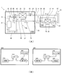
- FIG. 1 is an explanatory diagram of an air conditioner according to an embodiment of the present invention, in which (A) is an external perspective view of an indoor unit and an outdoor unit, and (B) is an XX cross-sectional view in (A).
- FIG. 2 is an explanatory diagram of an air conditioner according to an embodiment of the present invention, in which (A) is a refrigerant circuit diagram, and (B) is a block diagram of an outdoor unit control unit and an indoor unit control unit.
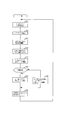
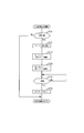
- FIG. 3 is a flowchart showing a process flow of the heating operation control.
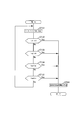
- FIG. 4 is a flowchart showing the flow of processing for protection control during heating operation.
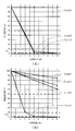
- FIG. 5 is data showing the residual rate of mold or bacteria at each indoor heat exchange temperature, (A) is data on mold, and (B) is data on E. coli.
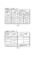
- FIG. 6 is a control table of each fan at the time of indoor heat exchange heating operation, (A) is an indoor fan control table, and (B) is an outdoor fan control table.
- FIG. 7 is a flowchart showing the flow of processing of the main routine of the indoor heat exchanger heating operation.
- FIG. 8 is a flowchart of the indoor heat exchanger heating operation, and is a flowchart showing the flow of processing for preheating operation control.
- FIG. 9 is a subroutine of the indoor heat exchange heating operation, and is a flowchart showing a flow of processing of indoor fan control during temperature maintenance.
- FIG. 10 is a subroutine of the indoor heat exchange heating operation, and is a flowchart showing a flow of processing of outdoor fan control during temperature maintenance.
- FIG. 11 is a flowchart showing a flow of processing of protection control during indoor heat exchanger heating operation.
- FIG. 12 is a flowchart showing a process flow of the wetting control operation.
- Compressor release interval time tfi ... Indoor fan release interval time Rc ; Compressor rotation speed Rcr ; Compressor release times Rotational speed Rcm ; Compressor minimum rotational speed Rfi ... Indoor fan rotational speed Rfia ... Indoor fan rotational speed Rfir ... Indoor fan release rotational speed Rfim ; Indoor fan minimum rotational speed Rfip ... Indoor fan initial rotational speed Rfo ... Outdoor fan rotational speed Rfoa: outdoor fan rotation speed before heating Rfob: outdoor fan rotation speed during maintenance D: expansion valve opening Dp: predetermined expansion valve opening
- an air conditioner 1 includes an outdoor unit 2 installed outdoors, and is installed indoors and connected to the outdoor unit 2 with a liquid pipe 4 and a gas pipe 5.
- An indoor unit 3 is provided.
- the indoor unit 3 includes an indoor unit housing 30 that has a horizontally long and substantially rectangular parallelepiped shape.
- the indoor unit housing 30 is formed by a top panel 30a, a right panel 30b, a left panel 30c, a bottom panel 30d, and a front panel 30e. Each of these panels is formed using a resin material.
- the top panel 30a is formed in a substantially square shape to form the top surface of the indoor unit housing 30. As shown in FIG. 1B, the top panel 30a is provided with a suction port 30f for taking indoor air into the interior of the indoor unit 3. Although illustration is omitted, the suction port 30f is formed in a lattice shape.
- the right side panel 30b and the left side panel 30c form the left and right side surfaces of the indoor unit housing 30.
- the right side panel 30b and the left side panel 30c are formed in curved surfaces having a predetermined curvature, and are symmetric.
- the bottom panel 30d is formed in a substantially square shape to form the bottom surface of the indoor unit housing 30. As shown in FIG. 1B, a base 30j, which will be described later, is fixed to the bottom panel 30d.
- the front panel 30e is formed in a substantially square shape and is disposed so as to cover the front surface of the indoor unit housing 30.
- the front panel 30 e forms the design surface of the indoor unit 3.
- the top panel 30a is provided with the suction port 30f, and below the front panel 30e, indoor air that has been heat-exchanged with the refrigerant by the indoor heat exchanger 31 described later is placed indoors.
- An outlet 30g for blowing out is provided.
- the ventilation path 30h that connects the suction port 30f and the outlet 30g is provided with an indoor fan 32 that sucks indoor air from the inlet 30f and blows it out from the outlet 30g.
- an indoor heat exchanger 31 having a bent portion 30n and having an inverted V shape is disposed above the indoor fan 32.
- the indoor heat exchanger 31 and the indoor fan 32 are fixed to a base 30j for attaching the indoor unit 3 to the wall surface.
- the blower outlet 30g is formed by the lower part of the base 30j and the lower surface of the casing 30k attached to the front panel 30e.
- the upper surfaces of the base 30j and the casing 30k are a drain pan 30m that receives the condensed water generated in the indoor heat exchanger 31.
- the air outlet 30g is provided with two upper and lower wind direction plates 35 that deflect the air blown from the air outlet 30g in the vertical direction.
- Each of the two up-and-down air direction plates 35 is formed of a resin material, and when the indoor unit 3 is not in operation, each of the up-and-down air direction plates 35 can be rotated to close the outlet 30g. It is said that.
- Each vertical wind direction plate 35 is fixed to a rotating shaft (not shown), and each vertical wind direction plate 35 rotates in the vertical direction to deflect the air blown from the outlet 30g in the vertical direction.
- a plurality of left and right wind direction plates 36 that deflect the air blown from the blower outlet 30g in the left-right direction are provided on the upstream side of the blower outlet 30g as viewed from the vertical wind direction plate 35 (inside the indoor unit housing 30). ing.
- Each of the left and right wind direction plates 36 is formed of a resin material and is fixed to a rotation shaft (not shown). When each left and right wind direction plate 36 rotates in the left and right direction, the air blown from the outlet 30g is deflected in the left and right direction. To do.
- a filter 38 for removing dust contained in the air taken into the indoor unit 3 is provided on the upstream side of the indoor heat exchanger 31 (between the indoor heat exchanger 31 and the suction port 30f) in the ventilation path 30h.
- the filter 38 is formed, for example, by braiding fibers made of a resin material into a mesh shape.
- each device constituting the outdoor unit 2 and the indoor unit 3 and the refrigerant circuit of the air conditioner 1 in which the outdoor unit 2 and the indoor unit 3 are connected by refrigerant piping will be described in detail with reference to FIG. .
- the outdoor unit 2 and the indoor unit 3 are connected by the liquid pipe 4 and the gas pipe 5 which are refrigerant pipes.
- the shutoff valve 25 of the outdoor unit 2 and the liquid pipe connection portion 33 of the indoor unit 3 are connected by the liquid pipe 4.
- the shutoff valve 26 of the outdoor unit 2 and the gas pipe connection part 34 of the indoor unit 3 are connected by the gas pipe 5.
- the refrigerant circuit 10 of the air conditioner 1 is configured as described above.
- the outdoor unit 2 includes a compressor 21, a four-way valve 22, an outdoor heat exchanger 23, an outdoor fan 27, a closing valve 25 to which the liquid pipe 4 is connected, and a closing valve 26 to which the gas pipe 5 is connected.
- the expansion valve 24 and the outdoor unit control means 200 are provided. And these each apparatus except the outdoor fan 27 and the outdoor unit control means 200 is mutually connected by each refrigerant
- the compressor 21 is a variable capacity compressor that can change the operating capacity by controlling the rotation speed by an inverter (not shown).
- the refrigerant discharge side of the compressor 21 is connected to the port a of the four-way valve 22 by a discharge pipe 61.
- the refrigerant suction side of the compressor 21 is connected to the port c of the four-way valve 22 by a suction pipe 66.
- the four-way valve 22 is a valve for switching the direction in which the refrigerant flows, and has four ports a, b, c, and d.
- the port a is connected to the refrigerant discharge side of the compressor 21 by the discharge pipe 61 as described above.
- the port b is connected to one refrigerant inlet / outlet of the outdoor heat exchanger 23 by a refrigerant pipe 62.
- the port c is connected to the refrigerant suction side of the compressor 21 by the suction pipe 66 as described above.
- the port d is connected to the shutoff valve 26 and the outdoor unit gas pipe 64.
- the outdoor heat exchanger 23 exchanges heat between the refrigerant and the outside air taken into the outdoor unit 2 by the rotation of the outdoor fan 27 described later.
- one refrigerant inlet / outlet of the outdoor heat exchanger 23 is connected to the port b of the four-way valve 22 by the refrigerant pipe 62, and the other refrigerant inlet / outlet is connected to the closing valve 25 by the outdoor unit liquid pipe 63.
- the expansion valve 24 is, for example, an electronic expansion valve.
- the expansion valve 24 adjusts the amount of refrigerant flowing through the indoor unit 3 by adjusting the opening degree of the expansion valve 24 according to the cooling capacity and heating capacity required by the indoor unit 3.
- the outdoor fan 27 is formed of a resin material and is disposed in the vicinity of the outdoor heat exchanger 23.
- the outdoor fan 27 is rotated by a fan motor (not shown) to take outside air from a suction port (not shown) of the outdoor unit 2 into the outdoor unit 2, and the outdoor air exchanged heat with the refrigerant in the outdoor heat exchanger 23. It discharges from the blower outlet which is not illustrated to the exterior of the outdoor unit 2.
- the outdoor unit 2 is provided with the following three sensors.
- the discharge pipe 61 is provided with a discharge temperature sensor 71 that detects the temperature of the refrigerant discharged from the compressor 21.
- An outdoor heat exchanger temperature sensor 72 that detects the temperature of the outdoor heat exchanger 23 (hereinafter referred to as an outdoor heat exchanger temperature) is provided at a substantially intermediate portion of a refrigerant path (not shown) of the outdoor heat exchanger 23.
- An outdoor air temperature sensor 73 that detects the temperature of the outside air flowing into the outdoor unit 2, that is, the outside air temperature, is provided near the suction port (not shown) of the outdoor unit 2.
- the outdoor unit control means 200 is mounted on a control board stored in an electrical component box (not shown) of the outdoor unit 2. As shown in FIG. 2B, the outdoor unit control means 200 includes a CPU 210, a storage unit 220, a communication unit 230, and a sensor input unit 240.
- the storage unit 220 includes a ROM and a RAM, and stores detection values corresponding to detection programs from the control program of the outdoor unit 2 and various sensors, control states of the compressor 21 and the outdoor fan 27, and the like.
- the communication unit 230 is an interface that performs communication with the indoor unit 3.
- the sensor input unit 240 captures detection results from various sensors of the outdoor unit 2 and outputs them to the CPU 210.
- CPU210 takes in the detection result in each sensor of outdoor unit 2 mentioned above via sensor input part 240.
- FIG. the CPU 210 takes in a control signal transmitted from the indoor unit 3 via the communication unit 230.
- the CPU 210 performs drive control of the compressor 21 and the outdoor fan 27 based on the detection results and control signals taken in.
- the CPU 210 performs switching control of the four-way valve 22 based on the detection results and control signals taken in.
- the CPU 210 adjusts the opening degree of the expansion valve 24 based on the acquired detection result and control signal.
- the indoor unit 3 includes a liquid pipe connection portion 33 to which the liquid pipe 4 is connected, a gas A gas pipe connecting portion 34 to which the pipe 5 is connected and an indoor unit control means 300 are provided.
- These devices other than the indoor fan 32, the up / down air direction plate 35, the left / right air direction plate 36, the filter 38, and the indoor unit control means 300 are connected to each other through the refrigerant pipes described in detail below, and are connected to the refrigerant circuit 10.
- the indoor unit refrigerant circuit 10b that constitutes a part of the indoor unit refrigerant circuit 10b is configured.
- the indoor heat exchanger 31 exchanges heat between indoor air taken into the indoor unit 3 through the suction port 30f of the indoor unit 3 by rotation of the refrigerant and the indoor fan 32, and one refrigerant inlet / outlet is connected to the liquid pipe.
- the other refrigerant inlet / outlet port is connected to the gas pipe connection part 34 and the indoor unit gas pipe 68.
- the indoor heat exchanger 31 functions as an evaporator when the indoor unit 3 performs a cooling operation, and functions as a condenser when the indoor unit 3 performs a heating operation.
- coolant piping is connected by welding, a flare nut, etc.
- the indoor fan 32 is formed of a resin material, and is arranged on the downstream side of the indoor heat exchanger 31 in the ventilation path 30h as described above.
- the indoor fan 31 is rotated by a fan motor (not shown), thereby taking indoor air into the indoor unit 3 from the suction port 30f of the indoor unit 3, and converting the indoor air heat exchanged with the refrigerant in the indoor heat exchanger 31 to the indoor unit 3. It blows out into the room from 30g of the air outlet.
- the indoor unit 3 is provided with two sensors described below.
- An indoor heat exchange temperature sensor 74 that detects the temperature of the indoor heat exchanger 31 (hereinafter referred to as the indoor heat exchange temperature) is provided at a substantially intermediate portion of the refrigerant path (not shown) of the indoor heat exchanger 31. Further, as shown in FIG. 1B, between the suction port 30f of the indoor unit 3 and the filter 38, the temperature of the air sucked into the interior of the indoor unit 3 from the suction port 30f, that is, the indoor temperature for detecting the indoor temperature. A sensor 75 is provided.
- the indoor unit control means 300 is mounted on a control board stored in an electrical component box (not shown) of the indoor unit 3. As shown in FIG. 2B, the indoor unit control means 300 includes a CPU 310, a storage unit 320, a communication unit 330, and a sensor input unit 340.
- the storage unit 320 includes a ROM and a RAM, and stores a control program for the indoor unit 3, detection values corresponding to detection signals from various sensors, a control state of the indoor fan 32, and the like.
- the communication unit 330 is an interface for communicating with the outdoor unit control means 200 of the outdoor unit 2.
- the sensor input unit 340 takes in the detection results of the indoor heat exchanger temperature sensor 74 and the indoor temperature sensor 75 of the indoor unit 3 and outputs them to the CPU 110.
- CPU310 takes in the detection result in each sensor of indoor unit 3 mentioned above via sensor input part 340. Further, the CPU 310 takes in an operation information signal including an operation mode (cooling operation / heating operation), an air volume, and the like transmitted from a remote controller (not shown) operated by the user via the communication unit 330. The CPU 310 performs drive control of the indoor fan 32, the up / down air direction plate 35, and the left / right air direction plate 36 based on the detection result and the operation information signal taken in.
- an operation information signal including an operation mode (cooling operation / heating operation), an air volume, and the like transmitted from a remote controller (not shown) operated by the user via the communication unit 330.
- the CPU 310 performs drive control of the indoor fan 32, the up / down air direction plate 35, and the left / right air direction plate 36 based on the detection result and the operation information signal taken in.
- the high-pressure refrigerant discharged from the compressor 21 flows through the discharge pipe 61 and flows into the four-way valve 22, and flows from the four-way valve 22 through the refrigerant pipe 62 to the outdoor heat exchanger. 23.
- the refrigerant flowing into the outdoor heat exchanger 23 is condensed by exchanging heat with the outside air taken into the outdoor unit 2 by the rotation of the outdoor fan 27.
- the refrigerant that has flowed out of the outdoor heat exchanger 23 into the outdoor unit liquid pipe 63 is reduced in pressure when passing through the expansion valve 24 that has an opening degree corresponding to the cooling capacity required by the user in the indoor unit 3 and is closed. It flows into the liquid pipe 4 through the valve 25.
- the refrigerant flowing through the liquid pipe 4 and flowing into the indoor unit 3 through the liquid side connection portion 33 flows through the indoor unit liquid pipe 67 and flows into the indoor heat exchanger 31, and from the suction port 30 f by the rotation of the indoor fan 32. It evaporates by exchanging heat with the indoor air taken into the ventilation path 30h of the indoor unit 3.
- the indoor heat exchanger 31 functions as an evaporator, and the indoor unit 3 is installed when the indoor air that has exchanged heat with the refrigerant in the indoor heat exchanger 31 is blown into the room through the outlet 30g. The room is cooled.
- the refrigerant that has flowed out of the indoor heat exchanger 31 flows through the indoor unit gas pipe 68 and flows into the gas pipe 5 through the gas side connection portion 34.
- the refrigerant flowing through the gas pipe 5 and flowing into the outdoor unit 2 through the closing valve 26 sequentially flows through the outdoor unit gas pipe 64, the four-way valve 22, and the suction pipe 66, and is sucked into the compressor 21 and compressed again.
- the high-pressure refrigerant discharged from the compressor 21 flows through the discharge pipe 61 and flows into the four-way valve 22, and flows from the four-way valve 22 through the outdoor unit gas pipe 64 to the closing valve. It flows into the gas pipe 5 through 26.
- the refrigerant flowing through the gas pipe 5 flows into the indoor unit 3 through the gas pipe connection part 34.
- the refrigerant flowing into the indoor unit 3 flows through the indoor unit gas pipe 68 and flows into the indoor heat exchanger 31, and the indoor air taken into the ventilation path 30 h of the indoor unit 3 from the suction port 30 f by the rotation of the indoor fan 32. Heat exchange to condense.
- the indoor heat exchanger 31 functions as a condenser, and the indoor air exchanged with the refrigerant in the indoor heat exchanger 31 is blown into the room from the outlet 30g, whereby the indoor unit 3 is installed. The room is heated.
- the refrigerant that has flowed out of the indoor heat exchanger 31 flows through the indoor unit liquid pipe 67 and flows into the liquid pipe 4 through the liquid pipe connecting portion 33.
- the refrigerant flowing through the liquid pipe 4 and flowing into the outdoor unit 2 through the shut-off valve 25 flows through the outdoor unit liquid pipe 63 and has an opening degree corresponding to the heating capacity required by the user in the indoor unit 3. When passing through the expansion valve 24, the pressure is reduced.
- the refrigerant that has passed through the expansion valve 24 and has flowed into the outdoor heat exchanger 23 evaporates by exchanging heat with the outside air taken into the outdoor unit 2 by the rotation of the outdoor fan 27.
- the refrigerant that has flowed out of the outdoor heat exchanger 23 into the refrigerant pipe 62 flows through the four-way valve 22 and the suction pipe 66, is sucked into the compressor 21, and is compressed again.
- the outdoor unit control means 200 and the indoor unit control means 300 described above constitute the control means of the present invention. Therefore, in the description of the subsequent control and processing including FIG. 3, the control body of the air conditioner 1 will be described using the control means, and the control body of the individual devices of the outdoor unit 2 and the indoor unit 3 will be described. The description will be made using the outdoor unit control means 200 (CPU 210) and the indoor unit control means 300 (CPU 310) as appropriate.
- the control means takes in the room temperature (hereinafter referred to as the room temperature Ti) and reads out the set temperature (hereinafter referred to as the set temperature Tp) (ST1). .
- the CPU 310 of the indoor unit control means 300 takes in the room temperature Ti detected by the room temperature sensor 75 periodically (for example, every 30 seconds) via the sensor input unit 340.
- CPU 310 reads set temperature Tp that has been set by the operation of a remote controller (not shown) by the user and stored in storage unit 320.
- control means calculates the temperature difference between the set temperature Tp read in ST1 and the captured room temperature Ti (hereinafter referred to as temperature difference ⁇ T) (ST2). Specifically, the CPU 310 calculates the temperature difference ⁇ T by subtracting the room temperature Ti from the set temperature Tp.
- the control means drives the compressor 21 with the rotational speed of the compressor 21 (hereinafter referred to as the compressor rotational speed Rc) corresponding to the temperature difference ⁇ T calculated in ST2 (ST3).
- the CPU 310 transmits the compressor rotation speed Rc corresponding to the calculated temperature difference ⁇ T to the outdoor unit 2 via the communication unit 330.
- the CPU 210 of the outdoor unit control means 200 that has received the compressor speed Rc transmitted from the indoor unit 3 via the communication unit 230 drives the compressor 21 with the received compressor speed Rc.
- the control means sets the opening degree of the expansion valve 24 (hereinafter referred to as the expansion valve opening degree D) to an opening degree corresponding to the heating capacity required by the user in the indoor unit 3 (ST4).
- the CPU 310 adjusts the expansion valve opening D so that the discharge temperature of the compressor 21 detected by the discharge temperature sensor 71 during the heating operation becomes a predetermined target temperature.
- the control means drives the outdoor fan 27 with the rotational speed of the outdoor fan 27 (hereinafter referred to as outdoor fan rotational speed Rfo) corresponding to the compressor rotational speed Rc determined in ST3 (ST5).
- the CPU 210 drives the outdoor fan 27 at the outdoor fan rotational speed Rfo corresponding to the compressor rotational speed Rc.
- the control means determines whether or not the air volume of the conditioned air blown from the outlet 30g of the indoor unit 3 by the user is automatically set (ST6). If the air volume is set to automatic (ST6-Yes), the control means uses the indoor fan 32 at the rotational speed of the indoor fan 32 (hereinafter referred to as indoor fan rotational speed Rfi) corresponding to the temperature difference ⁇ T calculated at ST2. 32 is driven (ST7). If the air volume is not set to automatic (ST6-No), the control means drives the indoor fan 32 at the indoor fan rotation speed Rfi according to the air volume set by the user (ST8). Specifically, the CPU 310 drives the indoor fan 32 at the indoor fan rotation speed Rfi according to either the temperature difference ⁇ T or the air volume set by the user.
- the control means controls the vertical and horizontal wind direction plates 35 and 36 so that the wind direction set by the user is obtained (ST9), and returns the process to ST1. Specifically, if the user setting is “swing”, the CPU 310 automatically rotates the vertical wind direction plate 35 up and down and automatically rotates the left and right wind direction plate 36 left and right. If the user's setting is a predetermined position, the up / down wind direction plate 35 and the left / right wind direction plate 36 are rotated so as to be the position set by the user.
- the control means takes in the temperature of the indoor heat exchanger 31 (hereinafter referred to as indoor heat exchange temperature Tc) and the discharge temperature of the compressor 21 (hereinafter referred to as discharge temperature Td) (ST11).
- the CPU 310 periodically captures the indoor heat exchange temperature Tc detected by the indoor heat exchange temperature sensor 74 via the sensor input unit 340 (for example, every 30 seconds).
- the CPU 210 fetches the discharge temperature Td detected by the discharge temperature sensor 71 periodically (for example, every 30 seconds) via the sensor input unit 240.
- the control means determines whether or not the indoor heat exchange temperature Tc captured in ST11 is equal to or higher than a predetermined temperature (hereinafter referred to as a first threshold indoor heat exchange temperature Tch1) (ST12). Specifically, CPU 310 reads out first threshold indoor heat exchange temperature Tch1 stored in advance in storage unit 320 and compares it with indoor heat exchange temperature Tc.
- the first threshold indoor heat exchange temperature Tch1 is obtained by performing a test or the like in advance, and is based on the indoor heat exchange temperature Tc corresponding to the upper limit value of the use range of the discharge pressure of the compressor 21 described above.
- the temperature is a predetermined low temperature, for example 55 ° C.
- the control means sets the rotation speed of the compressor 21 to a predetermined compressor release interval time (hereinafter referred to as compressor release interval). Every time (denoted as time tc), the predetermined compressor release rotational speed (hereinafter referred to as compressor release rotational speed Rcr) is decreased (ST16). Specifically, the CPU 310 transmits a signal indicating that the indoor heat exchange temperature Tc is equal to or higher than the first threshold indoor heat exchange temperature Tch1 to the outdoor unit 2 via the communication unit 330, and communicates this signal.
- the CPU 210 received via the unit 230 controls the compressor 21 so that the rotation speed is reduced by the compressor release rotation speed Rcr at each compressor release interval time tc from the current compressor rotation speed Rc.
- the compressor release interval time tc and the compressor release rotation speed Rcr are values in which the effect of reducing the indoor heat exchange temperature Tc by performing a test or the like in advance is confirmed, for example, the compressor release interval The time tc is 60 seconds, and the compressor release rotational speed Rcr is 2 rps.
- the control means that has finished the processing of ST16 takes in the indoor heat exchange temperature Tc (ST17), and determines whether the taken-in indoor heat exchange temperature Tc is equal to or higher than the first threshold indoor heat exchange temperature Tch1 (ST18). Specifically, the CPU 310 takes in the indoor heat exchange temperature Tc, and determines whether or not the taken in indoor heat exchange temperature Tc is equal to or higher than the first threshold indoor heat exchange temperature Tch1.
- the control unit returns the process to ST11. If the captured indoor heat exchange temperature Tc is equal to or higher than the first threshold indoor heat exchange temperature Tch1 (ST18-Yes), the control means stops the heating operation (ST19) and ends the heating operation protection control. Specifically, if the captured indoor heat exchange temperature Tc is equal to or higher than the first threshold indoor heat exchange temperature Tch1, the CPU 310 stops the indoor fan 32 and the captured indoor heat exchange temperature Tc is equal to the first threshold indoor heat exchange temperature Tc1. A signal indicating that the temperature is equal to or higher than the alternating temperature Tch1 is transmitted to the outdoor unit 2 via the communication unit 330. CPU210 which received this signal via the communication part 230 stops the compressor 21 and the outdoor fan 27. FIG.
- the control means detects that the discharge temperature Td detected in ST11 is a predetermined first threshold discharge temperature (hereinafter referred to as “first threshold discharge temperature”). It is determined whether the temperature is lower than a predetermined second threshold discharge temperature (hereinafter referred to as a second threshold discharge temperature Tdh2) higher than the first threshold discharge temperature Tdh1 (hereinafter referred to as a first threshold discharge temperature Tdh1). ST13).
- the CPU 210 periodically captures the discharge temperature Td detected by the discharge temperature sensor 71 via the sensor input unit 240 (for example, every 30 seconds), and stores the captured discharge temperature Td in the storage unit 220. It is determined whether or not the first threshold discharge temperature Tdh1 or higher is lower than the second threshold discharge temperature Tdh2.
- the first threshold discharge temperature Tdh1 and the second threshold discharge temperature Tdh2 are obtained by performing a test or the like in advance and stored in the storage unit 220, and the use range of the discharge pressure of the compressor 21 described above.
- the first threshold discharge temperature Tdh1 is 105 ° C.
- the second threshold discharge temperature Tdh2 is 115 ° C.
- the control means compresses the rotation speed of the compressor 21 at every compressor release interval time tc.
- the machine release rotation speed Rcr is decreased (ST15), and the process returns to ST11. Since the process of ST15 has the same contents as the process of ST16 described above, detailed description thereof is omitted.
- the control unit determines that the captured discharge temperature Td is equal to or higher than the second threshold discharge temperature Tdh2. It is determined whether or not there is (ST14). Specifically, the CPU 210 determines whether or not the fetched discharge temperature Td is equal to or higher than the second threshold discharge temperature Tdh2.
- the control means advances the process to ST19. If the taken discharge temperature Td is not equal to or higher than the second threshold discharge temperature Tdh2 (ST14-Yes), that is, if the taken discharge temperature Td is lower than the first threshold discharge temperature Tdh1, the control unit returns the process to ST11. .
- the indoor heat exchange heating operation means that the refrigerant circuit 10 of the air conditioner 1 is in the same state as in the heating operation, and the temperature of the indoor heat exchanger 31 is higher than the temperature (about 40 ° C.) during the heating operation.
- the purpose is to kill mold and bacteria and reduce the number.
- a remote controller (not shown) for operating the indoor unit 3 is provided with a button for instructing the start of the indoor heat exchanger heating operation. When the user operates this button, the indoor heat exchanger heating operation is performed.
- the indoor heat exchange heating operation may be automatically executed at the end of the cooling operation or the dehumidifying operation.
- the indoor heat exchanger heating operation is optimal for the air conditioner 1 such that the indoor unit 3 includes a human detection sensor and is detected when the human detection sensor detects that the user is not in the room.
- the indoor heat exchange heating operation may be performed by judging the timing.
- the applicant conducted an experiment to greatly increase the number of molds and bacteria by maintaining the indoor heat exchange temperature Tc at 55 ° C. or higher for 10 minutes when performing the above-described indoor heat exchange heating operation. Found that can be reduced.
- Tc indoor heat exchange temperature
- FIG. 5A is a graph of Cladopolis (hereinafter referred to as “mold”), which is a kind of mold (black mold) that looks dark.
- the horizontal axis of the graph in FIG. 5A is the heating time (unit: minutes) that is the time for maintaining the indoor heat exchange temperature Tc at 40 ° C., 45 ° C., and 50 ° C., and the vertical axis is the heating time.
- This is the mold residual rate (mold residual rate in FIG. 5A. Unit:%) with the number of molds (the number of mold colonies) at 0 minutes (before heating) as 100.
- the indoor heat exchange temperature Tc when the indoor heat exchange temperature Tc is 40 ° C., the number of molds hardly changes even when the heating time is 10 minutes, and the mold residual rate after 10 minutes has passed is almost 100. %.
- the indoor heat exchange temperature Tc when the indoor heat exchange temperature Tc is set to 45 ° C. or 50 ° C., the mold residual rate becomes smaller than 10% at any indoor heat exchange temperature Tc when the heating time becomes 5 minutes.
- the indoor heat exchange temperature Tc when the indoor heat exchange temperature Tc is set to 50 ° C., the mold residual rate when the heating time is 5 minutes is less than 1%, and the number of molds is greatly reduced in a short time.
- FIG. 5B is a graph for E. coli which is a kind of bacteria.
- the horizontal axis of the graph of FIG. 5B is the heating time (unit: minutes) that is the time for maintaining the indoor heat exchange temperature Tc at 40 ° C., 45 ° C., 50 ° C., and 55 ° C.
- the vertical axis is E. coli survival rate with the number of E. coli at 100 minutes when the heating time is 0 minutes (before heating) (bacterial survival rate in FIG. 5B, unit:%).
- the bacteria remaining rate does not become 50% or less even when the heating time is 10 minutes, and the number of bacteria can be significantly reduced. I can't say.
- the indoor heat exchange temperature Tc is 55 ° C.
- the bacterial survival rate becomes less than 10% when the heating time becomes 4 minutes, and the bacterial survival rate when the heating time becomes 5 minutes. If the heating time is further extended to 10 minutes, the bacterial residual rate is less than 1%. That is, the number of bacteria can be greatly reduced by maintaining the indoor heat exchange temperature Tc at 55 ° C. for 10 minutes.
- the indoor heat exchange temperature Tc is set to 55 ° C. or more, and this state is maintained for 10 minutes. It is preferable to continue. This is because the entire surface of mold and bacteria is covered with condensed water, so that the amount of heat acting on mold and bacteria from condensed water acts on mold and bacteria only from the surface of the indoor heat exchanger 31 without condensed water. This is due to the fact that the amount of heat increases.
- the dew condensation water generated in the indoor heat exchanger 31 when the air conditioner 1 is cooled is driven by driving the indoor fan 32 and passing the air through the indoor heat exchanger 31 after the cooling operation is completed. Even if the drying operation to evaporate is performed, the V-shaped bent portion 30n in the indoor heat exchanger 31 and the portion where the air near the drain pan 30m is difficult to pass through cannot be completely dried. Thus, even if the condensed water stays for a long time without being completely dried, if the indoor heat exchange heating operation of the present embodiment is performed, the condensed water staying in a place where it is difficult for the air to pass as described above. Since the temperature is higher than or equal to ° C., it is possible to significantly reduce the mold and bacteria remaining in these places.
- the indoor fan control table 400 shown in FIG. 6A is obtained by performing a test or the like in advance and is stored in the storage unit 320 of the indoor unit control means 300.
- the indoor fan control table 400 controls the indoor fan 32 on the basis of the indoor fan control table 400 when the indoor heat exchanger 31 functions as a condenser during the indoor heat exchange operation. It has been found that Tc can be maintained in the range of 55 ° C to 57 ° C.
- the indoor fan rotation speed Rfi (unit: rpm) is set according to each of the indoor heat exchange temperature Tc (unit: ° C.) and when the indoor heat exchange temperature Tc is rising / maintaining / decreasing. It has been established.
- Tc rise when the indoor heat exchange temperature Tc rises (“Tc rise” in FIG. 6A), two indoor heat exchange temperatures Tc detected at a time are used to detect the indoor heat exchange detected earlier. This is a case where the indoor heat exchange temperature Tc detected after the temperature Tc is high.
- the indoor heat exchange temperature Tc is maintained (in FIG. 6A, “when Tc is maintained”), the previously detected indoor heat exchange temperature Tc and the later detected indoor heat exchange temperature Tc are the same.
- the two indoor heat exchange temperatures Tc detected at a time are used to detect the indoor heat exchange temperature previously detected. This is a case where the indoor heat exchange temperature Tc detected after Tc is low.
- the indoor fan rotation speed Rfi when “Tc rises” is the rotation speed obtained by adding 70 rpm to the current indoor fan rotation speed Rfi when the indoor heat exchange temperature Tc is 57 ° C. or higher. .
- the current indoor fan rotation speed Rfi is not changed.
- the indoor heat exchange temperature Tc is not less than 53 ° C. and less than 55 ° C., and when the indoor heat exchange temperature Tc is less than 53 ° C., the rotation speed is obtained by subtracting 10 rpm from the current indoor fan rotation speed Rfi. .
- the indoor heat exchanger temperature Tc is set to Each time it is detected (for example, every 30 seconds), the indoor fan rotation speed Rfi is decreased by 10 rpm. Thereby, the air quantity which flows into the indoor heat exchanger 31 decreases, and the indoor heat exchange temperature Tc quickly reaches 55 ° C. or higher.
- the indoor heat exchange temperature Tc is 55 ° C. or more and less than 57 ° C. when the indoor heat exchange temperature Tc is rising, the indoor fan rotation speed Rfi is not changed. Thereby, the air quantity which flows into the indoor heat exchanger 31 does not change, and the indoor heat exchange temperature Tc is maintained in a range of 55 ° C. or more and less than 57 ° C.
- the indoor heat exchange temperature Tc is 59 ° C. or more by increasing the indoor fan rotation speed Rfi by 70 rpm and increasing the amount of air flowing to the indoor heat exchanger 31. I am trying not to become.
- the indoor fan rotation speed Rfi when “Tc is maintained” is the rotation speed obtained by adding 50 rpm to the current indoor fan rotation speed Rfi when the indoor heat exchange temperature Tc is 57 ° C. or higher.
- the current indoor fan rotation speed Rfi is not changed.
- the rotation speed is obtained by subtracting 30 rpm from the current indoor fan rotation speed Rfi.
- the rotation speed is obtained by subtracting 40 rpm from the current indoor fan rotation speed Rfi.
- the indoor fan rotation speed Rfi is set to 40 rpm each time the indoor heat exchange temperature Tc is detected (for example, every 30 seconds). Lower it step by step.
- the indoor fan rotation speed Rfi is decreased by 30 rpm each time the indoor heat exchange temperature Tc is detected. Thereby, the air quantity which flows into the indoor heat exchanger 31 decreases, and the indoor heat exchange temperature Tc quickly reaches 55 ° C. or higher.
- the indoor fan rotation is greater than when “Tc is increased” even at the same indoor heat exchange temperature Tc.
- the rotational speed at which the indoor fan rotational speed Rfi is reduced is increased so that the number Rfi is lowered.
- the indoor heat exchange temperature Tc is 55 ° C. or more and less than 57 ° C. when the indoor heat exchange temperature Tc is not changed, the indoor fan rotation speed Rfi is not changed. Thereby, the air quantity which flows into the indoor heat exchanger 31 does not change, and the indoor heat exchange temperature Tc is maintained in a range of 55 ° C. or more and less than 57 ° C.
- the indoor heat exchange temperature Tc is 59 ° C. or more by increasing the indoor fan rotation speed Rfi by 50 rpm and increasing the amount of air flowing to the indoor heat exchanger 31. I am trying not to become.
- the indoor fan rotation is greater than when “Tc is increased” even at the same indoor heat exchange temperature Tc.
- the rotational speed applied to the indoor fan rotational speed Rfi is lowered so that the number Rfi is lowered.
- the fan rotation speed Rfi is not changed.
- the rotation speed is obtained by subtracting 40 rpm from the current indoor fan rotation speed Rfi. .
- the indoor heat exchanger temperature Tc is lower than 53 ° C. when the indoor heat exchanger temperature Tc is decreasing, or when the indoor heat exchanger temperature Tc is not lower than 53 ° C. and lower than 55 ° C.
- the indoor heat exchanger temperature Tc is Each time it is detected (for example, every 30 seconds), the indoor fan rotation speed Rfi is decreased by 40 rpm to decrease the amount of air flowing through the indoor heat exchanger 31. As a result, the amount of air flowing through the indoor heat exchanger 31 is reduced so that the indoor heat exchange temperature Tc quickly reaches 55 ° C. or higher.
- the indoor fan rotation is performed so that the indoor fan rotation speed Rfi is lower than that when “Tc is maintained” even when the indoor heat exchange temperature Tc is the same.
- the number of revolutions subtracted from the number Rfi is increased.
- the indoor fan rotational speed Rfi is set. Do not change. Thereby, the air quantity which flows into the indoor heat exchanger 31 does not change, and the indoor heat exchange temperature Tc is maintained in a range of 55 ° C. or more and less than 57 ° C. It should be noted that when “Tc is lowered”, it is considered that the indoor heat exchange temperature Tc is less likely to rise than when “Tc is maintained”, and therefore, when the indoor heat exchange temperature Tc is 55 ° C. or higher, the indoor fan rotational speed Rfi is Even if it is not changed, the indoor heat exchange temperature Tc does not become 59 ° C. or higher.
- the indoor fan rotation speed Rfi is increased or decreased.
- the upper limit rotational speed is, for example, 900 rpm
- the lower limit rotational speed is, for example, 300 rpm. If the indoor fan rotational speed Rfi is increased by 900 rpm by increasing the rotational speed determined by the indoor fan control table 400, then the indoor fan rotational speed Rfi is increased to 900 rpm even when the indoor fan rotational speed Rfi is increased. Maintained.
- the indoor fan rotational speed Rfi is decreased by the rotational speed determined by the indoor fan control table 400 to reach 300 rpm, the indoor fan rotational speed Rfi is 300 rpm even when the indoor fan rotational speed Rfi is subsequently decreased. Maintained.
- 300 rpm of the said minimum rotation speed in indoor heat exchanger heating operation is made into rotation speed lower than the minimum rotation speed (for example, 420 rpm) of the indoor fan 32 at the time of heating operation. This is because in the indoor heat exchange heating operation, the indoor heat exchange temperature Tc rises quickly by reducing the amount of air flowing into the indoor heat exchanger 31 by reducing the rotational speed of the indoor fan 32 as much as possible. It is.
- the outdoor fan control table 500 illustrated in FIG. 6B is obtained by performing a test or the like in advance and is stored in the storage unit 220 of the outdoor unit control means 200.
- the outdoor fan control table 500 is used when the indoor fan 32 is controlled based on the indoor fan control table 400 so that the indoor heat exchange temperature Tc is maintained at 55 ° C. to 57 ° C. during the indoor heat exchange heating operation. It has been found that by controlling the outdoor fan 27 based on the fan control table 500, the discharge pressure of the compressor 21 can be prevented from exceeding the upper limit value of the use range.
- the rotational speed of the outdoor fan (unit: ° C.) detected by the outdoor temperature sensor 73 and the indoor temperature Ti (unit: ° C.) and the outdoor fan rotation speed (unit: ° C.) are determined.
- the outdoor fan rotation speed Rfo is set to 0 rpm regardless of the indoor temperature Ti.
- the outdoor fan rotation speed Rfo is 0 rpm if the indoor temperature Ti is 27 ° C. or higher, and if the indoor temperature Ti is lower than 27 ° C.
- the fan rotation speed Rfo is 190 rpm.
- the outdoor fan rotation speed Rfo is set to the same control as that in the heating operation, that is, the rotation speed according to the compressor rotation speed Rc.
- the outdoor air temperature To is 24 ° C. or higher
- the evaporation pressure in the outdoor heat exchanger 23 that functions as an evaporator during the indoor heat exchanger heating operation is higher than when the outdoor air temperature To is less than 24 ° C.
- the condensation pressure in the indoor heat exchanger 31 functioning as a condenser also increases, so that the discharge pressure of the compressor 21 increases and may exceed the upper limit of the use range. Therefore, when the outdoor air temperature To is 24 ° C. or higher, the outdoor fan rotation speed Rfo is 0 rpm, that is, stopped regardless of the indoor temperature Ti, thereby reducing the evaporation capacity in the outdoor heat exchanger 23 and increasing the evaporation pressure. Do not.
- the room heat functioning as a condenser is compared with the case where the room temperature Ti is less than 27 ° C.
- the condensation capacity in the exchanger 31 is reduced and the condensation pressure is increased.
- the outdoor fan rotation speed Rfo is set to 0 rpm, that is, the outdoor heat exchanger 23 is stopped. Decrease evaporation capacity so that evaporation pressure does not increase.
- the outdoor temperature To is 16 ° C. or higher and lower than 24 ° C. and the indoor temperature Ti is lower than 27 ° C.
- the condensation pressure is lower than that when the indoor temperature Ti is 27 ° C. or higher.
- the discharge pressure of the compressor 21 is unlikely to exceed the upper limit of the use range. Therefore, when the outdoor air temperature To is 16 ° C. or higher and lower than 24 ° C. and the indoor temperature Ti is lower than 27 ° C., the outdoor fan rotational speed Rfo is set to the discharge pressure of the compressor 21 due to the increase in the evaporation pressure. Is driven at a rotation speed that does not exceed the upper limit of the use range, for example, 190 rpm, which is the rotation speed in the present embodiment. Thereby, while preventing the discharge pressure of the compressor 21 from being excessively increased, the evaporation pressure in the outdoor heat exchanger 23 is increased, and the condensation temperature in the indoor heat exchanger 31, that is, the indoor heat exchange temperature Tc is quickly increased.
- the outdoor fan rotation speed Rfo when the outdoor air temperature To is 16 ° C. or higher and lower than 24 ° C. and the indoor temperature Ti is lower than 27 ° C. during the indoor heat exchanger operation is 190 rpm.
- the lower rotational speed (for example, 500 rpm) of the outdoor fan 27 is set to a lower rotational speed. This is because in the indoor heat exchanger heating operation, the discharge pressure of the compressor 21 is likely to exceed the upper limit of the use range due to raising the indoor heat exchanger temperature Tc to a temperature higher than that in the heating operation.
- the outdoor fan rotational speed Rfo is set to the same control as that in the heating operation, that is, the rotational speed corresponding to the compressor rotational speed Rc regardless of the indoor temperature Ti.
- FIG. 7 is a main routine of processing performed by the control unit of the air conditioner 1 during the indoor heat exchanger heating operation.
- FIG. 8 is a subroutine of the processing performed by the control means during the indoor heat exchanger heating operation, and the pre-heating operation performed for the purpose of suppressing the generation of condensed water inside the indoor unit 3 before heating the indoor heat exchanger 31.
- the flow of processing related to control is shown.
- FIG. 9 is a subroutine of processing performed by the control means during the indoor heat exchanger heating operation.
- the indoor heat exchanger temperature Tc is set within the range of 55 ° C. to 57 ° C. using the indoor fan control table 400 shown in FIG.
- the flow of the process related to indoor fan control during temperature maintenance performed for the purpose of maintaining is shown.
- FIG. 10 is a subroutine of the processing performed by the control means during the indoor heat exchanger heating operation, and the indoor heat exchanger temperature Tc is set within the range of 55 ° C. to 57 ° C. using the outdoor fan control table 500 shown in FIG. 6 (B).
- the flow of the process regarding outdoor fan control at the time of temperature maintenance performed when maintaining is shown.
- Tc1 to Tc4 (hereinafter referred to as first indoor heat exchange temperature Tc1 to fourth indoor heat exchange temperature Tc4) shown in FIGS. 7 and 9 are second indoor heat exchange temperature Tc2 to fourth indoor heat. This corresponds to the indoor heat exchange temperature Tc described in the indoor fan control table 400, the second indoor heat exchange temperature Tc2 is 53 ° C., the third indoor heat exchange temperature Tc3 is 55 ° C., and the fourth indoor heat exchange temperature. Tc4 is 57 ° C.
- the first indoor heat exchange temperature Tc1 is a temperature at which a temperature maintenance operation described later is started, and a temperature lower than the second indoor heat exchange temperature Tc2 by a predetermined temperature, for example, 50 ° C.
- the third indoor heat exchange temperature Tc3 is the first temperature of the present invention
- the fourth indoor heat exchange temperature Tc4 is the second temperature of the present invention
- the first indoor heat exchange temperature Tc1 is the third temperature of the present invention. It is.
- the control means drives the compressor 21 at a predetermined minimum rotational speed (hereinafter referred to as a compressor minimum rotational speed Rcm) (ST42).
- the CPU 210 of the outdoor unit control means 200 reads the compressor minimum rotational speed Rcm stored in advance in the storage unit 220, and drives the compressor 21 at the read compressor minimum rotational speed Rcm.
- the minimum compressor rotation speed Rcm is obtained by conducting a test or the like in advance, and even in a situation where the indoor heat exchange temperature Tc is higher than that during normal heating operation in the indoor heat exchange heating operation, This is the rotational speed at which the discharge pressure of the compressor 21 has been found not to exceed the upper limit of the use range.
- the minimum compressor rotation speed Rcm is, for example, 30 rps.
- the control means sets the expansion valve 24 to a predetermined opening (hereinafter referred to as a predetermined expansion valve opening Dp) (ST43).
- a predetermined expansion valve opening Dp a predetermined opening stored in advance in the storage unit 220 so that the expansion valve opening D becomes the read predetermined expansion valve opening Dp.
- a drive pulse corresponding to a predetermined expansion valve opening Dp is applied to a step motor (not shown) of the expansion valve 24.
- the predetermined expansion valve opening Dp is obtained by performing a test or the like in advance, and when the indoor heat exchanger heating operation of the present invention is performed by the air conditioner 1, only the control of the indoor fan 32 is performed.
- the opening is such that an amount of the refrigerant necessary for setting the indoor heat exchange temperature Tc to a temperature in the range of 55 ° C. or higher and lower than 57 ° C. can be passed through the indoor heat exchanger 31.
- the predetermined expansion valve opening degree Dp is 200 pulses when expressed by the number of drive pulses applied to the expansion valve 24, for example.
- the control means sets the outdoor fan rotation speed Rfo to a rotation speed corresponding to the compressor rotation speed Rc (ST44). Specifically, the CPU 210 drives the outdoor fan 27 at the outdoor fan rotational speed Rfo corresponding to the compressor rotational speed Rc. Since the outdoor fan 27 is already driven by the pre-heating operation control described later at the time of performing the process of ST43, the outdoor fan rotational speed Rfo is changed to a rotational speed corresponding to the compressor rotational speed Rc in ST43.
- the outdoor fan rotation speed Rfo at this time is, for example, 500 rpm.
- the control means sets the indoor fan 32 to a predetermined rotation speed (hereinafter referred to as an indoor fan initial rotation speed Rfip) (ST45).
- the CPU 310 of the indoor unit control means 300 reads out the indoor fan initial rotational speed Rfip stored in advance in the storage unit 320, and the indoor fan 32 as the indoor fan initial rotational speed Rfip read out from the indoor fan rotational speed Rfi. Drive.
- the indoor fan initial rotational speed Rfip is obtained by performing a test or the like in advance, and is caused by the small amount of indoor air supplied to the indoor heat exchanger 31 by the rotation of the indoor fan 32.
- the indoor heat exchange temperature Tc can be increased as quickly as possible while preventing the indoor heat exchange temperature Tc from rapidly rising and stopping the protection by the indoor heat exchange heating operation protection control described later.
- the indoor fan initial rotational speed Rfip is, for example, 600 rpm. Further, at the time of performing the process of ST44, since the indoor fan 32 has already been driven by the pre-heating operation control described later, in ST44, the indoor fan rotation speed Rfi is changed to the indoor fan initial rotation speed Rfip.
- the control means places the vertical wind direction plate 35 in the horizontal position (ST46). Specifically, the CPU 310 rotates the vertical wind direction plate 35 so as to be in the horizontal position. If the up-and-down wind direction plate 35 is in the horizontal position, a part of the air heated by the indoor heat exchanger 31 and blown out from the outlet 30g can be sucked into the inlet 30f. Accordingly, the indoor heat exchange temperature Tc rises faster than when the up-and-down airflow direction plate 35 is set to a position other than the horizontal position.
- the control means starts measuring the timer 1 (ST47). Specifically, the CPU 310 has a timer measurement function, and the CPU 310 starts measuring the timer 1. Note that the timer measurement function may be provided in the CPU 210, or may be provided in addition to the CPU 210 and the CPU 310.
- the control means takes in the indoor heat exchange temperature Tc (ST48). Specifically, the CPU 310 periodically captures the indoor heat exchange temperature Tc detected by the indoor heat exchange temperature sensor 74 via the sensor input unit 340 (for example, every 30 seconds).
- control means determines whether or not the indoor heat exchange temperature Tc captured in ST48 is less than the first indoor heat exchange temperature Tc1 (ST49). Specifically, the CPU 310 reads the first indoor heat exchange temperature Tc1 from the storage unit 320 and compares it with the captured indoor heat exchange temperature Tc.
- the control means starts the measurement of the timer 1 in ST47, and then starts a predetermined time (hereinafter, the first predetermined time tp1). Is described) (ST58). Specifically, CPU 310 determines whether or not first predetermined time tp1 has elapsed since start of measurement of timer 1 in ST47.
- the first predetermined time tp1 is predetermined and stored in the storage unit 330, for example, 10 minutes.
- the control unit resets the timer 1 (ST61) and ends the indoor unit heat exchanger heating operation control.
- the CPU 310 resets the timer 1 and stops the indoor fan 31 and transmits a signal including the end of the indoor unit heat exchanger heating operation control to the outdoor unit 2 via the communication unit 330.
- CPU210 which received this signal via the communication part 230 stops the compressor 21 and the outdoor fan 27.
- the control means determines whether the current indoor fan rotational speed Rfi is a predetermined minimum rotational speed (hereinafter referred to as indoor fan minimum rotational speed Rfim). It is determined whether or not (ST59). Specifically, CPU 310 reads the indoor fan minimum rotational speed Rfim stored in advance in storage unit 320 and compares it with the current indoor fan rotational speed Rfi.
- the indoor fan minimum rotation speed Rfim is the lower limit rotation speed of the use range of the indoor fan 32, and is, for example, 300 rpm.
- the control means maintains the indoor fan minimum rotational speed Rfim (ST60). Driving continues at the rotational speed Rfim, and the process returns to ST48. Specifically, the CPU 310 continues to drive the indoor fan 32 at the indoor fan minimum rotational speed Rfim.
- the control means sets the indoor fan rotational speed Rfi to a predetermined indoor fan release interval time (hereinafter referred to as indoor fan release interval).
- indoor fan release interval a predetermined indoor fan release rotational speed
- the CPU 310 decreases the indoor fan rotation speed Rfi by the indoor fan release rotation speed Rfi at every indoor fan release interval time tfi.
- the indoor fan release interval time tfi and the indoor fan release rotation speed Rfir are determined in advance through a test or the like, and the indoor heat exchange temperature Tc is rapidly increased to protect the indoor heat exchange heating operation described later. It has been confirmed that the indoor heat exchanger temperature Tc is raised while suppressing the protection stop by the control.
- the indoor fan release interval time tfi is, for example, 60 seconds
- the indoor fan release rotation speed Rfir is, for example, 50 rpm.
- the processing of ST47 to ST49 and ST58 to ST62 described above is an operation for raising the indoor heat exchange temperature Tc in the indoor unit heat exchange heating operation to the first indoor heat exchange temperature Tc1 (hereinafter referred to as a temperature raising operation). To be described). By performing the temperature raising operation, the indoor heat exchange temperature Tc is set to the first indoor temperature Tc1 (in this embodiment, 50 ° C.) as soon as possible while preventing protection from being stopped by protection control during indoor heat exchange heating operation described later. ).
- the indoor heat exchanger heating operation is terminated when the indoor heat exchanger temperature Tc does not become equal to or higher than the first indoor heat exchanger temperature Tc1 even after the first predetermined time tp1 has elapsed. If the indoor heat exchange temperature Tc does not become equal to or higher than the first indoor heat exchange temperature Tc1 even after the temperature raising operation described above is performed for the first predetermined time tp1, the indoor heat exchange temperature Tc is unlikely to rise for some reason. It is for avoiding useless operation as a result of continuing the indoor heat exchanger heating operation as it is.
- the control means starts measuring the timer 2 (ST50). Specifically, CPU 310 starts measuring timer 2.
- control means executes indoor fan control during temperature maintenance, which is a subroutine for indoor heat exchange heating operation control (ST51), and also performs outdoor fan control during temperature maintenance, which is a subroutine for indoor heat exchange heating operation control. (ST52).
- indoor fan control during temperature maintenance and the outdoor fan control during temperature maintenance will be described later.
- the control means determines whether or not the flag is 1 (ST53). For example, the CPU 310 has this flag, and when the indoor heat exchange temperature Tc rises during the indoor heat exchange operation, the flag becomes the third indoor heat exchange temperature Tc3 (55 ° C. in the present embodiment) or higher for the first time. , 0 is changed to 1.
- the flag is set to 0 by default (at the time of factory shipment).
- the control means resets the timer 1 (ST63) and goes to ST56. Proceed with the process. Specifically, if the CPU 310 confirms the flag and is 1, the timer 1 is reset.
- the control means determines that the indoor heat exchange temperature Tc captured in ST48 is the third heat exchange temperature Tc. It is determined whether or not the indoor heat exchange temperature Tc3 is reached (ST54). Specifically, the CPU 310 reads out the third indoor heat exchange temperature Tc3 from the storage unit 320 and compares it with the captured indoor heat exchange temperature Tc.
- control means sets the flag to 1 and resets the timer 1 (ST55), and the process proceeds to ST56. To proceed. Specifically, CPU 310 sets the flag to 1 and resets timer 1.
- the control means starts the measurement of the timer 1 in ST47 and the first predetermined time tp1 has elapsed. Whether or not is determined (ST64). Note that the processing of ST63 is performed by the CPU 310 in the same manner as the processing of ST58.
- the control means If the first predetermined time tp1 has elapsed (ST64-Yes), the control means resets the timer 1 (ST65) and ends the indoor unit heat exchanger heating operation control. Note that the processing of ST65 is performed by the CPU 310 in the same manner as the processing of ST61. If the first predetermined time tp1 has not elapsed (ST64-No), the control unit returns the process to ST53.
- the indoor heat exchange heating operation is terminated. This is because if the indoor heat exchange temperature Tc does not become equal to or higher than the third indoor heat exchange temperature Tc3 even if the temperature raising operation and the temperature maintenance operation described later are performed for the first predetermined time tp1, the indoor heat exchange temperature Tc for some reason. This is for avoiding useless operation as a result of continuing the indoor heat exchanger heating operation as it is.
- the control means that has finished the process of ST55 determines whether or not a predetermined time (hereinafter referred to as a second predetermined time tp2) has elapsed since the start of the timer 2 measurement in ST50 (ST56). Specifically, CPU 310 determines whether or not second predetermined time tp2 has elapsed since the start of timer 2 measurement in ST50.
- the second predetermined time tp2 is predetermined and stored in the storage unit 330. In order to greatly reduce the number of molds and bacteria present in the indoor heat exchanger 31 described above, This is the time for maintaining the heat exchange temperature Tc at 55 ° C. or higher, for example, 10 minutes.
- the control unit returns the process to ST51. If the second predetermined time tp2 has not elapsed (ST56-No), the control unit returns the process to ST51. If the second predetermined time tp2 has elapsed (ST56-Yes), the control means resets the timer 2 and resets the flag (ST57), and ends the indoor unit heat exchanger heating operation control. Specifically, the CPU 310 resets the timer 2 and the flag. In addition, the CPU 310 stops the indoor fan 31 and transmits a signal including that the indoor unit heat exchanger heating operation control is terminated to the outdoor unit 2 via the communication unit 330. CPU210 which received this signal via the communication part 230 stops the compressor 21 and the outdoor fan 27. FIG.
- the processes from ST50 to ST56 and ST63 to ST65 described above maintain the indoor heat exchange temperature Tc at or above the third indoor heat exchange temperature Tc3 (55 ° C. in the present embodiment) for the second predetermined time tp2.
- This is processing related to the operation to be performed (hereinafter referred to as temperature maintenance operation).
- control means determines whether or not the cooling operation was performed before the indoor heat exchanger heating operation (ST71). If the cooling operation is not performed (ST71-No), the control means ends the pre-heating operation control. If the cooling operation is being performed (ST71-Yes), the control means starts measuring the timer 3 (ST72). Specifically, CPU 310 starts measuring timer 3.
- the control means drives the indoor fan 32 with the indoor fan rotation speed Rfi as a predetermined rotation speed (hereinafter referred to as the pre-heating indoor fan rotation speed Rfia) (ST73).
- the CPU 310 drives the indoor fan 32 with the indoor fan rotation speed Rfi as the pre-heating indoor fan rotation speed Rfia.
- the indoor fan rotation speed Rfia before heating is obtained by performing a test or the like in advance, and during a third predetermined time tp3 described later, the indoor air is passed through the indoor unit 3 for cooling.
- the number of revolutions can suppress the generation of dew condensation water due to the temperature difference between the temperature of the indoor unit 3 and the indoor heat exchange temperature Tc during the temperature rising operation by warming the indoor unit 3 cooled during operation.
- the indoor fan rotation speed Rfia before heating is, for example, 900 rpm.
- the control means drives the outdoor fan 27 with the outdoor fan rotational speed Rfo as a predetermined rotational speed (hereinafter referred to as the pre-heating outdoor fan rotational speed Rfoa) (ST74).
- the CPU 210 drives the outdoor fan 27 with the outdoor fan rotation speed Rfo as the pre-heating outdoor fan rotation speed Rfoa.
- the pre-heating outdoor fan rotation speed Rfoa is obtained in advance by performing a test or the like, and during the third predetermined time tp3 described later, the outdoor unit control means 200 (particularly, the heat generated during the cooling operation).
- the number of rotations is such that the temperature of the outdoor unit control means 200 can be suppressed from being excessively increased when the indoor heat exchange heating operation is performed by cooling the inverter unit (not shown) that drives the compressor 21.
- the pre-heating outdoor fan rotation speed Rfoa is, for example, 650 rpm.
- the control means determines whether or not a predetermined time (hereinafter referred to as a third predetermined time tp3) has elapsed after starting the measurement of the timer 3 in ST72 (ST75). Specifically, CPU 310 determines whether or not third predetermined time tp3 has elapsed since the start of timer 3 measurement in ST75.
- the third predetermined time tp3 is predetermined and stored in the storage unit 330, and the indoor fan rotation speed Rfi is set to the pre-heating indoor fan rotation speed Rfia and the outdoor fan rotation speed Rfo is heated.
- the indoor unit 3 cooled during the cooling operation can be heated to the extent that no dew condensation water is generated during the heating operation, and the cooling operation This is the time during which the outdoor unit control means 200 that generated heat can be cooled.
- the third predetermined time tp3 is, for example, 15 minutes.
- the control unit If the third predetermined time tp3 has not elapsed (ST75-No), the control unit returns the process to ST75. If the third predetermined time tp3 has elapsed (ST75-Yes), the control means resets the timer 3 (ST76), ends the pre-heating operation control, and returns to the main routine.
- the housing 30 of the indoor unit 3 cooled during the cooling operation is performed by performing the pre-heating operation control prior to the temperature raising operation. Can warm up.
- casing 30 resulting from the temperature difference of the temperature of the indoor unit 3 and indoor heat exchanger temperature Tc can be suppressed at the time of temperature rising operation, when performing indoor heat exchanger heating operation It is possible to prevent the dew condensation water from scattering from the air outlet 30g of the indoor unit 3 into the room.
- the outdoor unit control means 200 that is at a high temperature during the cooling operation with a high outside air temperature can be cooled.
- the CPU 310 takes in the indoor heat exchange temperature Tc (ST80).
- the CPU 310 uses the two indoor heat exchange temperatures Tc captured at a certain time, and the indoor heat exchange temperature Tc captured immediately before (for example, 30 seconds before) the most recently captured indoor heat exchange temperature Tc. Is calculated (hereinafter referred to as indoor heat exchange temperature difference ⁇ Tc) (ST81).
- CPU 310 determines whether or not the indoor heat exchanger temperature difference ⁇ Tc calculated in ST81 is greater than 0, that is, whether or not the indoor heat exchanger temperature Tc has increased (ST82). If the indoor heat exchanger temperature difference ⁇ Tc is greater than 0 (ST82-Yes), the CPU 310 refers to “when Tc rises” in the indoor fan rotation speed table 400 of FIG. Steps ST83 to ST85 are performed.
- the CPU 310 determines whether or not the current indoor heat exchange temperature Tc is lower than the third indoor heat exchange temperature Tc3 (ST83). If the current indoor heat exchange temperature Tc is lower than the third indoor heat exchange temperature Tc3 (ST83-Yes), the CPU 310 sets the indoor fan rotational speed Rfi as the rotational speed obtained by subtracting 10 rpm from the current indoor fan rotational speed Rfi ( ST86) Ends indoor fan control during temperature maintenance and returns to the main routine.
- the CPU 310 determines that the current indoor heat exchanger temperature Tc is equal to or greater than the third indoor heat exchanger temperature Tc3 and the fourth indoor heat exchanger temperature Tc3. It is determined whether it is less than Tc4 (ST84). If the current indoor heat exchange temperature Tc is not less than the third indoor heat exchange temperature Tc3 and less than the fourth indoor heat exchange temperature Tc4 (ST84-Yes), the CPU 310 does not change the indoor fan rotational speed Rfi (ST87). When the temperature is maintained, the indoor fan control is terminated and the process returns to the main routine.
- the current indoor heat exchange temperature Tc is not greater than or equal to the third indoor heat exchange temperature Tc3 and less than the fourth indoor heat exchange temperature Tc4 (ST84-No), that is, the current indoor heat exchange temperature Tc is equal to the fourth indoor heat exchange temperature Tc4. If it is above, CPU310 makes indoor fan rotation speed Rfi the rotation speed which added 70rpm to the current indoor fan rotation speed Rfi (ST85), ends indoor fan control at the time of temperature maintenance, and returns to the main routine.
- the CPU 310 determines whether or not there is (ST88). If the indoor heat exchange temperature difference ⁇ Tc is 0 (ST88-Yes), the CPU 310 refers to “when maintaining Tc” in the indoor fan rotation speed table 400 of FIG. Processing of ST89 to ST95 is performed.
- the CPU 310 determines whether or not the current indoor heat exchange temperature Tc is lower than the second indoor heat exchange temperature Tc2 (ST89). If the current indoor heat exchange temperature Tc is lower than the second indoor heat exchange temperature Tc2 (ST89-Yes), the CPU 310 sets the indoor fan rotation speed Rfi as the rotation speed obtained by subtracting 40 rpm from the current indoor fan rotation speed Rfi ( ST93) Ends indoor fan control during temperature maintenance and returns to the main routine.
- the CPU 310 determines that the current indoor heat exchange temperature Tc is equal to or greater than the second indoor heat exchange temperature Tc2 and the third indoor heat exchange temperature. It is determined whether it is less than Tc3 (ST90). If the current indoor heat exchange temperature Tc is equal to or greater than the second indoor heat exchange temperature Tc2 and less than the third indoor heat exchange temperature Tc3 (ST90-Yes), the CPU 310 calculates the indoor fan rotational speed Rfi from the current indoor fan rotational speed Rfi. As the number of revolutions reduced by 30 rpm (ST94), the indoor fan control is terminated when the temperature is maintained, and the process returns to the main routine.
- the CPU 310 determines that the current indoor heat exchanger temperature Tc is the third indoor heat exchanger temperature Tc. It is determined whether it is Tc3 or higher and lower than the fourth indoor heat exchange temperature Tc4 (ST91). If the current indoor heat exchange temperature Tc is not less than the third indoor heat exchange temperature Tc3 and less than the fourth indoor heat exchange temperature Tc4 (ST91-Yes), the CPU 310 does not change the indoor fan rotation speed Rfi (ST95). When the temperature is maintained, the indoor fan control is terminated and the process returns to the main routine.
- the current indoor heat exchange temperature Tc is not equal to or higher than the third indoor heat exchange temperature Tc3 and lower than the fourth indoor heat exchange temperature Tc4 (ST93-No), that is, the current indoor heat exchange temperature Tc is equal to the fourth indoor heat exchange temperature Tc4. If it is above, CPU310 makes indoor fan rotation speed Rfi the rotation speed which added 50rpm to the current indoor fan rotation speed Rfi (ST98), ends indoor fan control at the time of temperature maintenance, and returns to the main routine.
- the CPU 310 determines whether or not the current indoor heat exchange temperature Tc is lower than the third indoor heat exchange temperature Tc3 (ST96). If the current indoor heat exchanger temperature Tc is lower than the third indoor heat exchanger temperature Tc3 (ST96-Yes), the CPU 310 sets the indoor fan rotational speed Rfi to a rotational speed obtained by subtracting 40 rpm from the current indoor fan rotational speed Rfi ( ST98) Ends indoor fan control during temperature maintenance and returns to the main routine.
- the CPU 310 Without changing the indoor fan rotation speed Rfi (ST97), the indoor fan control is terminated when the temperature is maintained, and the process returns to the main routine.
- the indoor fan when performing indoor fan control during temperature maintenance using the indoor fan control table 400, the indoor fan is between the upper and lower rotational speeds (900 rpm and 300 rpm) of the indoor fan rotational speed Rfi.
- a rotational speed Rfi is set. If the indoor fan rotational speed Rfi is increased by 900 rpm by increasing the rotational speed determined by the indoor fan control table 400, the indoor fan rotational speed Rfi is maintained at 900 rpm even when the indoor fan rotational speed Rfi is subsequently increased. Is done.
- the indoor fan rotational speed Rfi is decreased by the rotational speed determined by the indoor fan control table 400 to reach 300 rpm, the indoor fan rotational speed Rfi is 300 rpm even when the indoor fan rotational speed Rfi is subsequently decreased. Maintained.
- the indoor heat exchange temperature Tc is set to the third indoor heat exchange by performing the indoor fan control during the temperature maintenance using the indoor fan control table 400 during the temperature maintenance operation performed during the indoor heat exchange heating operation.
- the CPU 210 takes in the room temperature Ti from the indoor unit 3 via the communication 230 and takes in the outside air temperature To detected by the outside air temperature sensor 73 via the sensor input unit 240 (ST111).
- the CPU 210 takes in the room temperature Ti and the outside air temperature To periodically (for example, every 30 seconds).
- the CPU 210 determines whether or not the outside air temperature To taken in in ST111 is lower than a predetermined first outside air temperature (hereinafter referred to as a first threshold outside air temperature Top1) (ST112).
- a predetermined first outside air temperature hereinafter referred to as a first threshold outside air temperature Top1
- the first threshold outside air temperature Top1 is the outside air temperature: 16 ° C. defined in the outdoor fan control table 500 of FIG.
- the CPU 210 refers to the outdoor fan control table 500 stored in the storage unit 220 and rotates the outdoor fan 27 in the compressor. Driving is performed at the outdoor fan rotation speed Rfo corresponding to the number Rc (ST117), the outdoor fan control at the time of temperature maintenance is terminated, and the process returns to the main routine.
- the CPU 210 determines that the taken-in outside air temperature To is equal to or higher than the first threshold outside air temperature Top1 and a predetermined second outside air temperature (hereinafter referred to as a second temperature). It is determined whether or not the temperature is below the threshold outside air temperature Top2 (ST113).
- the second threshold outside air temperature Top2 is higher than the first threshold outside air temperature Top1, and is, for example, the outside air temperature: 24 ° C. defined in the outdoor fan control table 500 in FIG. 6B.
- the CPU 210 Referring to outdoor fan control table 500 stored in storage unit 220, outdoor fan rotation speed Rfo is set to 0 rpm (ST118), that is, outdoor fan 27 is stopped and outdoor fan control is terminated when temperature is maintained. And return to the main routine.
- the CPU 210 determines that the room temperature Ti taken in at ST111 is a predetermined room temperature (hereinafter referred to as the threshold room temperature). It is determined whether it is less than (describes Tip) (ST114).
- the threshold indoor temperature Tip is the indoor temperature: 27 ° C. defined in the outdoor fan control table 500 in FIG.
- the CPU 210 determines whether or not the current outdoor fan rotation speed Rfo is 0 rpm (ST115).
- the CPU 210 proceeds to ST118, that is, maintains the state where the outdoor fan 27 is stopped. If the current outdoor fan rotation speed Rfo is not 0 rpm (ST115-No), CPU 210 sets outdoor fan rotation speed Rfo as a predetermined rotation speed (hereinafter referred to as maintenance outdoor fan rotation speed Rfob) (ST116). When the temperature is maintained, the outdoor fan control is terminated and the process returns to the main routine.
- the maintenance-time outdoor fan rotation speed Rfob is the outdoor fan rotation speed Rfo: 190 rpm defined in the outdoor fan control table 500 of FIG.
- the outdoor fan control is performed during the temperature maintenance using the outdoor fan control table 500.
- the indoor heat exchange temperature Tc is maintained in the range of 55 ° C. to 57 ° C. by controlling the outdoor fan 27 based on the outdoor fan control table 500, the discharge pressure of the compressor 21 is within the usage range. It is possible not to exceed the upper limit.
- FIG. 11 ⁇ Protection control during indoor heat exchanger operation>
- protection control during indoor heat exchanger heating operation so that the discharge pressure of the compressor 21 does not exceed the upper limit value of the use range during the indoor heat exchanger heating operation described above will be described.
- ST represents a process step, and the number following this represents a step number.
- the indoor heat exchange heating operation protection control is executed when the indoor heat exchange heating operation is performed, and is different from the heating operation protection control executed when the heating operation is performed. It is.
- the control means takes in the indoor heat exchange temperature Tc, the discharge temperature Td, the temperature of the outdoor heat exchanger 23 (hereinafter referred to as the outdoor heat exchange temperature Te), and the outdoor air temperature To (ST131).
- the indoor heat exchange temperature Tc and the discharge temperature Td are captured in the same manner as ST11 in the heating operation protection control described with reference to FIG.
- the outside air temperature To is taken in by the same method as ST111 in the outdoor fan control during temperature maintenance described with reference to FIG.
- the CPU 210 takes in the outdoor heat exchange temperature Te detected by the outdoor heat exchange temperature sensor 72 periodically (for example, every 30 seconds) via the sensor input unit 240.
- the control means is equal to or higher than a predetermined temperature (hereinafter referred to as second threshold indoor heat exchange temperature Tch2) at which the indoor heat exchange temperature Tc captured in ST131 is higher than the first threshold indoor heat exchange temperature Tch1. It is determined whether or not (ST132). Specifically, CPU 310 reads out second threshold indoor heat exchange temperature Tch2 stored in advance in storage unit 320 and compares it with indoor heat exchange temperature Tc.
- the second threshold indoor heat exchange temperature Tch2 is obtained in advance through a test or the like, is higher than the first threshold indoor heat exchange temperature Tch1, and uses the discharge pressure of the compressor 21 described above.
- the temperature is a predetermined temperature lower than the indoor heat exchange temperature Tc corresponding to the upper limit value of the range.
- the second threshold indoor heat exchange temperature Tch2 is, for example, 59 ° C.
- the control means stops the indoor heat exchanger heating operation (ST136) and performs protection control during the indoor heat exchanger heating operation. End the process involved. In addition, you may stop the driving
- the opening degree D of the expansion valve 24 is made larger than that in the indoor heat exchanger heating operation, and the indoor fan rotation speed Rfi is also increased, so that the discharge pressure of the compressor 21 is higher than that in the indoor heat exchanger heating operation. Also decreases.
- the control unit determines whether or not the discharge temperature Td captured in ST131 is equal to or higher than the first threshold discharge temperature Tdh1. (ST133). Specifically, the CPU 210 determines whether or not the discharge temperature Td is equal to or higher than the first threshold discharge temperature Tdh1.
- the control means advances the process to ST136.
- the control means determines that the outdoor heat exchange temperature Te taken in ST131 is a predetermined outdoor heat exchange temperature (hereinafter, the threshold outdoor heat exchange temperature). It is determined whether or not (described as Teh) (ST134). Specifically, the CPU 210 determines whether or not the captured outdoor heat exchange temperature Te is equal to or higher than the threshold outdoor heat exchange temperature Teh.
- the threshold outdoor heat exchange temperature Teh is obtained in advance by performing a test or the like and stored in the storage unit 220. If the outdoor heat exchange temperature Te is equal to or higher than the threshold outdoor heat exchange temperature Teh, compression is performed. The temperature at which the suction pressure of the compressor 21 rises and the compression ratio of the compressor 21 (the ratio between the discharge pressure and the suction pressure) may fall below the lower limit value of the use range.
- the control means determines that the outside air temperature To taken in ST131 is a predetermined outside air temperature (hereinafter referred to as a third threshold outside air temperature Top3). It is determined whether or not it is (described) (ST135). Specifically, the CPU 310 determines whether or not the taken-in outside temperature To is equal to or higher than the third threshold outside temperature Top3.
- the third threshold outside air temperature Top3 is obtained by performing a test or the like in advance and stored in the storage unit 220. When the outside air temperature To is equal to or higher than the third threshold outside air temperature Top3, the indoor heat exchange is performed.
- the third threshold outside temperature Top3 is higher than the first threshold outside temperature Top1 and the second threshold outside temperature Top2 described above, and is 43 ° C., for example.
- the control unit If the taken-in outside temperature To is not equal to or higher than the third threshold outside temperature Top3 (ST134-No), the control unit returns the process to ST131. If the taken-out outside temperature To is equal to or higher than the third threshold outside temperature Top3 (ST134-Yes), the control unit returns the process to ST136.
- the indoor heat exchange temperature Tc can be maintained at 55 ° C. to 57 ° C., and if the indoor heat exchange temperature Tc becomes equal to or higher than the second threshold indoor heat exchange temperature Tch2, the compressor 21 Therefore, it is possible to suppress the discharge pressure of the compressor 21 from exceeding the upper limit value of the use range.
- the indoor heat exchange temperature Tc is maintained at 55 ° C. to 57 ° C. in the indoor heat exchange heating operation, the discharge temperature Td of the compressor 21 is likely to rise and the discharge pressure is likely to rise.
- the protection control during indoor heat exchange heating operation includes the stop of the compressor 21 due to the outdoor heat exchange temperature Te that is not included in the protection control during heating operation. It is considered that the indoor heat exchange heating operation of the present invention is often performed in the summer when cooling operation is performed in which the possibility of mold and bacteria breeding is increased by the condensed water generated in the indoor heat exchanger 31.
- the outdoor air temperature To is high and the outdoor air temperature To is high, so that in the indoor heat exchanger heating operation, the outdoor heat exchanger temperature Te of the outdoor heat exchanger 23 that functions as an evaporator increases.
- the suction pressure of the compressor 21 may increase due to the increase in the outdoor heat exchange temperature Te.
- the compressor 21 is stopped to prevent the suction pressure of the compressor 21 from increasing. Moreover, it can suppress that the compression ratio of the compressor 21 falls below the lower limit of the use range.
- the wetting control operation may be performed as follows.
- the indoor heat exchange temperature is controlled so that the surface of the indoor heat exchanger 31 is wetted with condensed water having a specific amount of water based on the temperature and humidity of the indoor heat exchanger 31 after the cooling operation.
- the indoor heat exchange temperature is maintained at a high temperature in the presence of condensed water on the surface of the indoor heat exchanger 31, the residual rate of mold and bacteria existing on the surface of the indoor heat exchanger 31 is greatly increased. Can be reduced.
- an information signal including humidity information of the measured humidity is supplied from the indoor humidity sensor (not shown) that measures the relative humidity in the indoor unit 3 to the sensor input unit 340 of the indoor unit control means 300 in the indoor unit 3. Is done.
- the control means when the control means recognizes the end of the cooling operation, it stops the rotation of the indoor fan 32 in ST137.
- the rest of the indoor fan 32 suppresses evaporation of condensed water from the surface of the indoor heat exchanger 31.
- the control means may stop the rotation of the indoor fan 32, reduce the rotation speed of the indoor fan 32, or perform intermittent rotation.
- the rotation of the indoor fan 32 may be adjusted as appropriate according to the amount of condensed water.
- the control means specifies the wet amount of the indoor heat exchanger 31 from the amount of condensed water generated on the surface of the indoor heat exchanger 31 in ST138. In specifying the wetting amount, the control means estimates the saturated water vapor amount from the output signals of the indoor temperature sensor 75 and the indoor humidity sensor. The control means specifies the amount of condensed water from the estimated saturated water vapor amount and the values of duration and elapsed time measured by a timer (not shown) incorporated in the indoor unit 3. Generally, after the cooling operation, the temperature of the indoor heat exchanger 31 is low, and condensed water is generated on the surface of the indoor heat exchanger 31.
- the control means cools the indoor heat exchanger 31 in ST139.
- the control means instructs the operations of the expansion valve 24 and the compressor 21 that lower the evaporation temperature of the refrigerant in the indoor heat exchanger 31.
- the temperature of the indoor heat exchanger 31 decreases and the generation of condensed water is promoted. Sufficient wetting is ensured on the surface of the indoor heat exchanger 31.
- Wet heat sterilization that can reduce the number of bacteria by killing bacteria at a temperature lower than the temperature in a dry state by giving heat to bacteria and mold in a high humidity state to a predetermined prescribed amount of wetness In order to carry out, it should just be set to the amount of water which does not lose the effectiveness of wet heat sterilization by evaporating during the heating of the indoor heat exchanger 31.
- the control means heats the indoor heat exchanger 31 in ST140. Refrigerant condensation is used for heating the indoor heat exchanger 31. At this time, the control means executes switching of the four-way valve 22. The four-way valve 22 is switched to the position during heating operation.
- the temperature of the indoor heat exchanger 31 during heating is set to 45 degrees Celsius or more.
- the temperature of the indoor heat exchanger 31 is set to 60 degrees Celsius or more.
- the indoor heat exchanger 31 is heated without evaporating condensed water on the surface of the indoor heat exchanger 31 without passing through the drying operation conventionally performed.
- the condensed water is heated by the indoor heat exchanger 31. Bacteria and mold are heated in the heated condensed water. Therefore, bacteria and molds are sterilized by wet heat. Can kill bacteria and mold to reduce the number.
- the temperature of the indoor heat exchanger 31 when the temperature of the indoor heat exchanger 31 is set to 45 degrees Celsius or higher, the dew condensation water is heated to 45 degrees Celsius or higher, so that the heat sterilization of bacteria and molds is effectively realized. Further, when the temperature of the indoor heat exchanger 31 is set to 60 degrees Celsius or more, the wet heat sterilization of bacteria and fungi is more effectively realized. The time to sterilization can be shortened. However, in order to suppress the evaporation of condensed water as much as possible, it is desirable that the temperature of the indoor heat exchanger 31 is set as low as possible at 70 degrees Celsius or less. In a state where the heat exchanger is dry, even if the temperature is set to 45 degrees Celsius or higher, it does not lead to sterilization of bacteria and mold.
- the opening degree of the expansion valve 24 and the rotation of the fans 27 and 32 are appropriately adjusted so that the temperature of the indoor heat exchanger 31 does not exceed 60 degrees and an overload condition is reached. It only has to be done.
- the control means determines completion of wet heat sterilization. For the determination, for example, the control means uses a timer. The timer measures the duration of the set temperature. When the duration of the set temperature reaches a specified value, the control means ends the wet heat sterilization. If the duration of the set temperature is less than the specified value, the control means continues the heating operation.
- the specified value for the duration of the set temperature may be equal to or longer than the time during which the effect of wet heat sterilization is obtained. According to the applicant's experiment, it has been found that the effect of wet heat sterilization can be obtained by setting it to 3 minutes or more for Escherichia coli and 5 minutes or more for black mold. Further, it has been found that 10 minutes or more is desirable for Legionella bacteria.
- control means observes the operation of the compressor 21 in ST142. If an overload of the compressor 21 is detected in heating up to the set temperature, the control means lowers the discharge temperature of the compressor 21 in ST7 and ends the heating operation. If no overload is detected, the heating operation is continued until it is determined in ST141 that the wet heat sterilization is completed.
- the overload condition of the compressor 21 set at the time of condensation is relaxed compared to the overload condition of the compressor 21 set at the time of heating operation. That is, the discharge temperature that is the threshold for the overload condition is set high, or the time until the overload protection operation is performed when the discharge temperature exceeds the threshold for the overload condition for a predetermined time is set long. Since the overload condition of the compressor 21 is relaxed during the wetting control operation, the indoor heat exchanger 31 can be heated to a higher temperature than during the heating operation. Bacterial and mold sterilization is achieved.
- a drying process in the indoor unit 3 may be performed following the wet heat sterilization process.
- the rotation of the indoor fan 32 is started while the heating of the indoor heat exchanger 31 is maintained.
- the control means specifies the number of rotations of the indoor fan 32.
- the rotation of the indoor fan 32 promotes evaporation of heated condensed water.
- the air outlet of the indoor unit 3 may be closed by the up / down wind direction plate 35.
- the control means may specify the minimum angle of the up / down wind direction plate 35. In this way, warm air blowing after the cooling operation is avoided. In this way, the drying and heating are continued following the wet heat sterilization treatment, thereby suppressing the growth of bacteria and mold remaining by the wet heat sterilization.
Landscapes
- Engineering & Computer Science (AREA)
- Chemical & Material Sciences (AREA)
- Combustion & Propulsion (AREA)
- Mechanical Engineering (AREA)
- General Engineering & Computer Science (AREA)
- Physics & Mathematics (AREA)
- Thermal Sciences (AREA)
- Air Conditioning Control Device (AREA)
Abstract
Priority Applications (3)
| Application Number | Priority Date | Filing Date | Title |
|---|---|---|---|
| CN201880014547.3A CN110382970B (zh) | 2017-02-28 | 2018-02-22 | 空气调节器 |
| AU2018228986A AU2018228986B2 (en) | 2017-02-28 | 2018-02-22 | Air conditioner |
| EP18761214.8A EP3591306A4 (fr) | 2017-02-28 | 2018-02-22 | Climatiseur |
Applications Claiming Priority (4)
| Application Number | Priority Date | Filing Date | Title |
|---|---|---|---|
| JP2017036408A JP6824779B2 (ja) | 2017-02-28 | 2017-02-28 | 空気調和機の防カビ方法およびそれを用いた空気調和機 |
| JP2017-036408 | 2017-02-28 | ||
| JP2017-184926 | 2017-09-26 | ||
| JP2017184926A JP6399181B1 (ja) | 2017-09-26 | 2017-09-26 | 空気調和機 |
Publications (1)
| Publication Number | Publication Date |
|---|---|
| WO2018159446A1 true WO2018159446A1 (fr) | 2018-09-07 |
Family
ID=63371216
Family Applications (1)
| Application Number | Title | Priority Date | Filing Date |
|---|---|---|---|
| PCT/JP2018/006448 WO2018159446A1 (fr) | 2017-02-28 | 2018-02-22 | Climatiseur |
Country Status (4)
| Country | Link |
|---|---|
| EP (1) | EP3591306A4 (fr) |
| CN (1) | CN110382970B (fr) |
| AU (1) | AU2018228986B2 (fr) |
| WO (1) | WO2018159446A1 (fr) |
Cited By (6)
| Publication number | Priority date | Publication date | Assignee | Title |
|---|---|---|---|---|
| JP6656472B1 (ja) * | 2018-10-16 | 2020-03-04 | 日立ジョンソンコントロールズ空調株式会社 | 空気調和機 |
| JP2020115065A (ja) * | 2019-01-18 | 2020-07-30 | 株式会社富士通ゼネラル | 空気調和機 |
| WO2021132413A1 (fr) * | 2019-12-23 | 2021-07-01 | 株式会社富士通ゼネラル | Climatiseur |
| JP2021099191A (ja) * | 2019-12-23 | 2021-07-01 | 株式会社富士通ゼネラル | 空気調和機 |
| CN113405233A (zh) * | 2021-06-25 | 2021-09-17 | 海信(山东)空调有限公司 | 空调器的杀菌控制方法及装置、空调器和存储介质 |
| CN113405238A (zh) * | 2021-06-25 | 2021-09-17 | 海信(山东)空调有限公司 | 空调器的杀菌控制方法及装置、空调器和存储介质 |
Families Citing this family (2)
| Publication number | Priority date | Publication date | Assignee | Title |
|---|---|---|---|---|
| CN111397128A (zh) * | 2020-03-27 | 2020-07-10 | 广东美的制冷设备有限公司 | 高温杀菌方法、频率控制方法和空调器 |
| CN111380152B (zh) * | 2020-03-27 | 2021-12-17 | 广东美的制冷设备有限公司 | 高温除菌控制方法、装置、空调器及存储介质 |
Citations (8)
| Publication number | Priority date | Publication date | Assignee | Title |
|---|---|---|---|---|
| JPS60147046A (ja) * | 1984-01-11 | 1985-08-02 | Matsushita Refrig Co | ヒ−トポンプ式空気調和機の除霜制御装置 |
| JPH0490453A (ja) * | 1990-08-01 | 1992-03-24 | Daikin Ind Ltd | 冷凍装置の運転制御装置 |
| JPH1062000A (ja) | 1996-08-20 | 1998-03-06 | Fujitsu General Ltd | 空気調和機 |
| JP2006125801A (ja) * | 2004-11-01 | 2006-05-18 | Matsushita Electric Ind Co Ltd | 空気調和機とその運転方法 |
| JP2006138545A (ja) * | 2004-11-12 | 2006-06-01 | Matsushita Electric Ind Co Ltd | 空気調和機とその運転方法 |
| JP2013083437A (ja) * | 2012-12-26 | 2013-05-09 | Mitsubishi Electric Corp | 空気調和装置、空気調和装置の安全管理方法 |
| JP2013167438A (ja) * | 2013-04-30 | 2013-08-29 | Daikin Industries Ltd | 空気調和装置 |
| JP2016065687A (ja) | 2014-09-25 | 2016-04-28 | パナソニックIpマネジメント株式会社 | 空気調和機 |
Family Cites Families (6)
| Publication number | Priority date | Publication date | Assignee | Title |
|---|---|---|---|---|
| JPH06129656A (ja) * | 1992-08-11 | 1994-05-13 | Osaka Gas Co Ltd | かび防止機能付き空調装置 |
| JP2000213795A (ja) * | 1999-01-25 | 2000-08-02 | Daikin Ind Ltd | 空気調和装置 |
| CN101526257B (zh) * | 2009-03-26 | 2010-11-10 | 宁波海诚电器有限公司 | 用于高温环境下空调制热时的压缩机的保护方法 |
| CN104913429B (zh) * | 2014-03-10 | 2018-04-13 | 广东美的制冷设备有限公司 | 空调器杀菌方法及空调器 |
| CN105987484B (zh) * | 2015-02-28 | 2019-01-11 | 青岛海尔空调器有限总公司 | 空调制热频繁防高温保护时的除霜控制方法及系统 |
| CN105180359B (zh) * | 2015-09-02 | 2018-04-20 | 珠海格力电器股份有限公司 | 一种防高温控制方法、装置和空调器 |
-
2018
- 2018-02-22 WO PCT/JP2018/006448 patent/WO2018159446A1/fr unknown
- 2018-02-22 AU AU2018228986A patent/AU2018228986B2/en active Active
- 2018-02-22 EP EP18761214.8A patent/EP3591306A4/fr active Pending
- 2018-02-22 CN CN201880014547.3A patent/CN110382970B/zh active Active
Patent Citations (8)
| Publication number | Priority date | Publication date | Assignee | Title |
|---|---|---|---|---|
| JPS60147046A (ja) * | 1984-01-11 | 1985-08-02 | Matsushita Refrig Co | ヒ−トポンプ式空気調和機の除霜制御装置 |
| JPH0490453A (ja) * | 1990-08-01 | 1992-03-24 | Daikin Ind Ltd | 冷凍装置の運転制御装置 |
| JPH1062000A (ja) | 1996-08-20 | 1998-03-06 | Fujitsu General Ltd | 空気調和機 |
| JP2006125801A (ja) * | 2004-11-01 | 2006-05-18 | Matsushita Electric Ind Co Ltd | 空気調和機とその運転方法 |
| JP2006138545A (ja) * | 2004-11-12 | 2006-06-01 | Matsushita Electric Ind Co Ltd | 空気調和機とその運転方法 |
| JP2013083437A (ja) * | 2012-12-26 | 2013-05-09 | Mitsubishi Electric Corp | 空気調和装置、空気調和装置の安全管理方法 |
| JP2013167438A (ja) * | 2013-04-30 | 2013-08-29 | Daikin Industries Ltd | 空気調和装置 |
| JP2016065687A (ja) | 2014-09-25 | 2016-04-28 | パナソニックIpマネジメント株式会社 | 空気調和機 |
Non-Patent Citations (1)
| Title |
|---|
| See also references of EP3591306A4 * |
Cited By (13)
| Publication number | Priority date | Publication date | Assignee | Title |
|---|---|---|---|---|
| JP6656472B1 (ja) * | 2018-10-16 | 2020-03-04 | 日立ジョンソンコントロールズ空調株式会社 | 空気調和機 |
| JP2020115065A (ja) * | 2019-01-18 | 2020-07-30 | 株式会社富士通ゼネラル | 空気調和機 |
| JP7247594B2 (ja) | 2019-01-18 | 2023-03-29 | 株式会社富士通ゼネラル | 空気調和機 |
| JP7031650B2 (ja) | 2019-12-23 | 2022-03-08 | 株式会社富士通ゼネラル | 空気調和機 |
| JP2021099192A (ja) * | 2019-12-23 | 2021-07-01 | 株式会社富士通ゼネラル | 空気調和機 |
| WO2021132412A1 (fr) * | 2019-12-23 | 2021-07-01 | 株式会社富士通ゼネラル | Climatiseur |
| JP7031651B2 (ja) | 2019-12-23 | 2022-03-08 | 株式会社富士通ゼネラル | 空気調和機 |
| JP2021099191A (ja) * | 2019-12-23 | 2021-07-01 | 株式会社富士通ゼネラル | 空気調和機 |
| CN114867969A (zh) * | 2019-12-23 | 2022-08-05 | 富士通将军股份有限公司 | 空调机 |
| CN114867968A (zh) * | 2019-12-23 | 2022-08-05 | 富士通将军股份有限公司 | 空调机 |
| WO2021132413A1 (fr) * | 2019-12-23 | 2021-07-01 | 株式会社富士通ゼネラル | Climatiseur |
| CN113405233A (zh) * | 2021-06-25 | 2021-09-17 | 海信(山东)空调有限公司 | 空调器的杀菌控制方法及装置、空调器和存储介质 |
| CN113405238A (zh) * | 2021-06-25 | 2021-09-17 | 海信(山东)空调有限公司 | 空调器的杀菌控制方法及装置、空调器和存储介质 |
Also Published As
| Publication number | Publication date |
|---|---|
| AU2018228986A1 (en) | 2019-08-22 |
| EP3591306A4 (fr) | 2020-12-23 |
| AU2018228986B2 (en) | 2021-02-25 |
| CN110382970B (zh) | 2021-06-08 |
| EP3591306A1 (fr) | 2020-01-08 |
| CN110382970A (zh) | 2019-10-25 |
Similar Documents
| Publication | Publication Date | Title |
|---|---|---|
| WO2018159446A1 (fr) | Climatiseur | |
| WO2018159444A1 (fr) | Climatiseur | |
| JP6399181B1 (ja) | 空気調和機 | |
| JP6447693B1 (ja) | 空気調和機 | |
| AU2018226754B2 (en) | Mold prevention method for air conditioner, and air conditioner using mold prevention method | |
| CN105972764A (zh) | 杀菌方法及杀菌装置、空调器 | |
| JP2019060527A (ja) | 空気調和機 | |
| CN110207313A (zh) | 空调器及其空调控制方法、控制装置和可读存储介质 | |
| JP6200241B2 (ja) | 乾燥装置 | |
| CN110332654A (zh) | 空调系统及空调系统化霜控制方法 | |
| JP4003101B2 (ja) | 空調機の制御方法及び装置 | |
| JP4228194B2 (ja) | 空気調和機の制御方法 | |
| JP5266951B2 (ja) | 衣類乾燥機 | |
| JP2008261555A (ja) | 空気調和機 | |
| JP2017044424A (ja) | 空気調和機 | |
| JP5505540B2 (ja) | 空気調和装置 | |
| JP2012207811A (ja) | 空気調和機 | |
| JPH1163632A (ja) | 空気調和装置 | |
| JP3963196B2 (ja) | 空調機の制御装置 | |
| JP5598392B2 (ja) | 空気調和機 | |
| JP4938536B2 (ja) | 空気調和機 | |
| JP7113775B2 (ja) | 空気調和機の防カビ方法およびそれを用いた空気調和機 | |
| JP2018036008A (ja) | 空気調和機 | |
| WO2021038744A1 (fr) | Climatiseur | |
| JP2018132210A5 (fr) |
Legal Events
| Date | Code | Title | Description |
|---|---|---|---|
| 121 | Ep: the epo has been informed by wipo that ep was designated in this application |
Ref document number: 18761214 Country of ref document: EP Kind code of ref document: A1 |
|
| ENP | Entry into the national phase |
Ref document number: 2018228986 Country of ref document: AU Date of ref document: 20180222 Kind code of ref document: A |
|
| NENP | Non-entry into the national phase |
Ref country code: DE |
|
| ENP | Entry into the national phase |
Ref document number: 2018761214 Country of ref document: EP Effective date: 20190930 |