WO2018159128A1 - 構造物 - Google Patents
構造物 Download PDFInfo
- Publication number
- WO2018159128A1 WO2018159128A1 PCT/JP2018/001184 JP2018001184W WO2018159128A1 WO 2018159128 A1 WO2018159128 A1 WO 2018159128A1 JP 2018001184 W JP2018001184 W JP 2018001184W WO 2018159128 A1 WO2018159128 A1 WO 2018159128A1
- Authority
- WO
- WIPO (PCT)
- Prior art keywords
- opening
- piece
- surface portion
- shape
- structure according
- Prior art date
- Legal status (The legal status is an assumption and is not a legal conclusion. Google has not performed a legal analysis and makes no representation as to the accuracy of the status listed.)
- Ceased
Links
Images








Classifications
-
- E—FIXED CONSTRUCTIONS
- E03—WATER SUPPLY; SEWERAGE
- E03B—INSTALLATIONS OR METHODS FOR OBTAINING, COLLECTING, OR DISTRIBUTING WATER
- E03B11/00—Arrangements or adaptations of tanks for water supply
- E03B11/10—Arrangements or adaptations of tanks for water supply for public or like main water supply
- E03B11/14—Arrangements or adaptations of tanks for water supply for public or like main water supply of underground tanks
-
- E—FIXED CONSTRUCTIONS
- E03—WATER SUPPLY; SEWERAGE
- E03B—INSTALLATIONS OR METHODS FOR OBTAINING, COLLECTING, OR DISTRIBUTING WATER
- E03B3/00—Methods or installations for obtaining or collecting drinking water or tap water
- E03B3/02—Methods or installations for obtaining or collecting drinking water or tap water from rain-water
-
- E—FIXED CONSTRUCTIONS
- E03—WATER SUPPLY; SEWERAGE
- E03B—INSTALLATIONS OR METHODS FOR OBTAINING, COLLECTING, OR DISTRIBUTING WATER
- E03B3/00—Methods or installations for obtaining or collecting drinking water or tap water
- E03B3/02—Methods or installations for obtaining or collecting drinking water or tap water from rain-water
- E03B3/03—Special vessels for collecting or storing rain-water for use in the household, e.g. water-butts
-
- E—FIXED CONSTRUCTIONS
- E03—WATER SUPPLY; SEWERAGE
- E03F—SEWERS; CESSPOOLS
- E03F1/00—Methods, systems, or installations for draining-off sewage or storm water
-
- Y—GENERAL TAGGING OF NEW TECHNOLOGICAL DEVELOPMENTS; GENERAL TAGGING OF CROSS-SECTIONAL TECHNOLOGIES SPANNING OVER SEVERAL SECTIONS OF THE IPC; TECHNICAL SUBJECTS COVERED BY FORMER USPC CROSS-REFERENCE ART COLLECTIONS [XRACs] AND DIGESTS
- Y02—TECHNOLOGIES OR APPLICATIONS FOR MITIGATION OR ADAPTATION AGAINST CLIMATE CHANGE
- Y02A—TECHNOLOGIES FOR ADAPTATION TO CLIMATE CHANGE
- Y02A20/00—Water conservation; Efficient water supply; Efficient water use
- Y02A20/108—Rainwater harvesting
Definitions
- the present invention relates to a structure that drains rainwater and the like.
- a rainwater storage facility provided under a ground such as a park, a parking lot, or a road
- a ground such as a park, a parking lot, or a road
- rainwater that falls on residential areas and roads is discharged into rivers and the like through side ditches and drainage grooves with little penetration into the ground.
- a large amount of rainfall such as torrential rain occurs in a short time, it overflows on the road. And cause traffic paralysis.
- a rainwater storage facility is provided under the ground such as parks, parking lots, or roads, and when a large amount of rain occurs, the rainwater is temporarily stored in the rainwater storage facility through a side ditch or a drainage ditch. It is done.
- An object of the present invention is to provide a structure capable of accurately draining rainwater and suppressing flooding even in a place where the groundwater level is shallow.
- the structure of the present invention A substantially flat structure composed of a central part formed by connecting a plurality of first pieces and a frame part formed by connecting a plurality of second pieces
- the first piece is A first surface portion having a plurality of first openings and a first leg portion provided at a position sandwiching a first passage portion formed on the side
- the second piece is A second surface portion having at least one second opening, and a second leg provided at a position sandwiching the second passage portion formed on the side
- the aperture ratio which is the area of the first opening with respect to the area of the first surface portion is 18% or more
- the porosity which is the ratio of the volume of the space containing the said 1st opening part, the said 2nd opening part, the said 1st channel
- the water permeability of the first surface portion can be improved, and by setting the porosity to 80% or more, rainwater that has passed through the asphalt layer is temporarily removed. Can be improved. Moreover, since this structure has a substantially flat plate shape, rainwater can be drained accurately and flooding on the road can be suppressed even in a place where the groundwater level is shallow.
- the structure of the present invention is
- the first piece has a hexagonal columnar shape
- the second piece has a quadrangular prism shape.
- the first piece a hexagonal column
- the strength of the first piece can be improved
- the second piece a quadrangular column
- the structure of the present invention is The width of the first opening and the second opening is 6 mm or more and 8 mm or less. Thereby, it can suppress that the aggregate of asphalt passes a hole, and the porosity falls, without making shaping
- the structure of the present invention is A rib having a height of 20 mm or less is formed on at least one of the boundary between the first surface portions, the boundary between the second surface portions, and the boundary between the first surface portion and the second surface portion. It is characterized by that. Thereby, the function which improves the shear force of a structure, and construction performance can be made compatible.
- the structure of the present invention is The second piece is formed with a fitting portion for fitting the structures together,
- the fitting portion includes a pair of concave portions and convex portions,
- the convex portion has a drum shape in which a central portion in a fitting direction swells.
- the structure of the present invention is
- the first piece and the second piece are made of resin. Thereby, productivity and weight reduction of a structure, a shape freedom degree, workability, and heat resistance can be exhibited.
- the structure of the present invention it is possible to accurately drain rainwater and suppress flooding even in a place where the groundwater level is shallow.
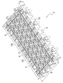
- FIG. 2 is a perspective view of the structure according to the embodiment viewed from the front side
- FIG. 3 is a perspective view of the structure viewed from the back side.
- the structure 2 is a substantially flat member formed of resin, and includes a central portion 4 and a frame portion 6 surrounding the periphery of the central portion 4.
- the short side length B of the structure 2 shown in FIG. 2 is designed so that it may be 4 times or more of the height C.
- the central part 4 is formed by connecting a plurality of first pieces 8 shown in FIG. 4 in the longitudinal direction and the short direction of the structure 2 respectively.
- each of the first pieces 8 has a hexagonal columnar shape, and six first openings 8b having a long round shape are formed in the first surface portion 8a having a turtle shell shape.
- the six first openings 8b radially extend from the center of the first surface portion 8a toward the side wall 8c, and project from the first surface portion 8a to the outer edge of the first surface portion 8a.
- the height of the first rib 8d is preferably 20 mm or less, and more preferably 2 mm or more and 15 mm or less.
- the shear resistance is improved. For example, even when the tire is switched, the asphalt layer 1 on the structure 2 is displaced. Can not be.
- a side wall 8c that defines the boundary between the first pieces 8 is formed on the side of the first piece 8, and a first passage portion 8e that is a rainwater passage is formed below the side wall 8c. Yes. Moreover, the 1st leg part 8f is extended in the position which pinched
- the frame portion 6 is formed by connecting the second pieces 10 shown in FIG. 5 in a frame shape around the central portion 4.
- each second piece 10 has a rectangular parallelepiped shape, and at least one second opening portion 10 b having an oblong shape is formed on the rectangular second surface portion 10 a. It is formed as described above.
- FIG. 5 shows an example in which three second openings 10b are arranged in the longitudinal direction of the second surface portion 10a.
- a second rib 10d is formed at the boundary of the second surface portion 10a so as to protrude from the second surface portion 10a.
- the height of the second rib 10d is preferably 20 mm or less, and more preferably 2 mm or more and 15 mm or less.
- a side wall 10c that defines the boundary between the second pieces 10 is formed on the side of the second piece 10, and a second passage portion 10e that is a rainwater passage is formed below the side wall 10c. Yes. Further, the second leg portion 10f extends downward from both sides of the side wall 10c at a position sandwiching the second passage portion 10e.
- the lower end of the second leg portion 10 f of the continuous second piece 10 can be in contact with the roadbed 3 (see FIG. 1) on which gravel is spread, in a T-shape. Since it is formed, it is difficult to pierce the roadbed 3. Therefore, the porosity of the structure 2 arrange
- the frame part 6 is provided with a connecting part for connecting the structures 2 to each other.
- the connecting portion includes a convex portion 12 a that protrudes outside the frame portion 6 and a concave portion 12 b (see FIG. 2) that is recessed inside the frame portion 6.
- the convex portion 12a when connecting the structures 2 to each other, the convex portion 12a is positioned directly above or directly below the concave portion 12b, and the structure 2 is moved in the height direction so that the convex portion 12a is moved. Fit into the recess 12b.
- the convex part 12a has a drum-shaped shape in which the central part swells so that the convex part 12a can be fitted into the concave part 12b from any of the upper and lower directions.
- ribs 14 having a substantially L-shaped cross section protruding from the second surface portion 10a are provided at the four corners of the frame portion 6. Since the structure 2 is stacked at the time of manufacture, the structure 2 can be easily stacked by providing the rib 14 on the second surface portion 10a. Moreover, since the 2nd leg part 10f of the 2nd piece 10 is hooked on the rib 14 also at the time of conveyance, load collapse can be prevented.
- the height of the rib 14 is preferably 2 mm or more and 50 mm or less, and more preferably 4 mm or more and 30 mm or less.
- the area of the first opening 8b (hereinafter referred to as the opening ratio) with respect to the area of the first surface portion 8a is preferably 18% or more, and may be 20% or more and 50% or less. More preferable.
- the structure 2 of the present embodiment is designed so that the aperture ratio is 18% or more.
- the water permeability of the 1st surface part 8a can be improved by making an aperture ratio 18% or more. The relationship between the aperture ratio and water permeability will be described in detail in Example 3.
- the structure 2 has a volume ratio of the space including the first opening 8b, the second opening 10b, the first passage 8e, and the second passage 10e with respect to the volume of the structure 2 (hereinafter referred to as “the structure 2”).
- the porosity is preferably 80% or more, and more preferably 82% or more and 96% or less.
- the porosity of the structure 2 of the present embodiment is designed to be 80% or more.
- the volume of the structure 2 is a volume represented by long side length A ⁇ short side length B ⁇ height C shown in FIG.
- the above-mentioned space refers to a portion where no resin exists.
- the porosity of the structure 2 When the porosity is increased in this way, the proportion of the resin is reduced, and a wide space is formed on the back surface of the structure 2 as shown in FIG. Therefore, by setting the porosity of the structure 2 to 80% or more, it is possible to improve the storage capacity for temporarily storing rainwater that has passed through the asphalt layer 1 (see FIG. 1). In addition, by increasing the opening area of the first passage portion 8e and the second passage portion 10e, rainwater stored in the structure 2 can be accurately flowed and drained in the horizontal direction.
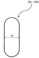
- the 1st opening part 8b and the 2nd opening part 10b have an oval shape extended in one direction and both ends were formed in the semicircle shape.
- the shape of the 1st opening part 8b and the 2nd opening part 10b is not necessarily limited to an oval shape, A round shape, a triangle, square shape, etc. may be sufficient.
- the width H of the parallel part which comprises the minimum width of the 1st opening part 8b and the 2nd opening part 10b is 6 mm or more and 8 mm or less. Thereby, it can suppress that asphalt passes an opening part at the time of construction. The relationship between the width H of the opening and the aggregate of the asphalt layer 1 will be described in detail in Example 1.
- the resin constituting the structure 2 is a thermoplastic resin or a thermosetting resin, and may contain additives such as various fibers, minerals, and metals.
- the type of resin and additive is not particularly limited as long as the characteristics as a structure are satisfied.
- the resin constituting the structure 2 is, for example, polypropylene (PP), polycarbonate (PC), polypropylene (PP) containing glass fiber (GF), or polycarbonate (PC) containing glass fiber (GF). May be formed. For this reason, the heat resistance and high strength which can be endured even if a load is applied in a state where the asphalt layer 1 is heated can be exhibited.
- the asphalt layer 1 is obtained by installing the structure 2 having a high surface opening ratio and a high overall porosity between the asphalt layer 1 and the roadbed 3 (see FIG. 1).
- Rainwater that has passed through the water can be drained accurately, and flooding on the road can be suppressed accurately.
- the structure 2 since the structure 2 is not large like a rainwater storage facility and is thin, it can be arranged near the ground surface. Therefore, it functions as an infiltration facility even in a place where the groundwater level is shallow, and flooding can be prevented accurately.
- the structure 2 has a high porosity, when drainage cannot be performed at a time such as heavy rain, the rainwater can be temporarily stored in the structure 2 and the amount of drainage can be adjusted.
- the structure 2 can be easily constructed when only one stage is arranged on the roadbed 3 without being stacked.
- the arrangement is not limited to only one stage, and two or more stages can be arranged and used.
- Example 1 size of opening
- Example 1 an experiment was conducted to determine the appropriate size of the first opening 8b and the second opening 10b.
- the experiment first, a plurality of perforated square plates 20 as shown in FIG.
- the breakdown of the plurality of perforated square plates 20 includes a hole radius R of 2.5 mm, a hole radius R of 3.5 mm, a hole radius R of 4 mm, and a hole radius R. Each having a thickness of 5 mm.
- FIG. 12 is a diagram showing asphalt marks left on the white paper 21 when the perforated square plate 20 having different hole radii R is used.
- FIG. 12A shows an asphalt mark when a holed square plate 20 having a hole radius R of 2.5 mm is used
- FIG. 12B shows a hole having a hole radius R of 3.5 mm.
- the asphalt trace when the perforated square plate 20 is used is shown.
- FIG. 12 (c) shows an asphalt mark when a holed square plate 20 having a hole radius R of 4 mm is used
- FIG. 12 (d) shows a hole having a hole radius R of 5 mm.
- the asphalt trace at the time of using the square plate 20 is shown.
- FIG. 12 shows that asphalt marks become clearer as the radius R of the hole of the perforated square plate 20 increases.
- the radius R of the hole is set to 2.5 mm, it is difficult for the asphalt to pass through, but it is difficult to form the perforated square plate 20 as the hole becomes smaller.
- the radius R of the hole is set to 5 mm, the asphalt aggregate passes through the hole and the porosity decreases.
- the radius R of the hole is preferably about 3 mm to 4.5 mm.
- Example 2 (Hole shape) In Example 2, examination was made as to what shape is appropriate for the first opening 8b and the second opening 10b.
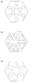
- FIG. 13A As the shape of the opening, as shown in FIG. 13A, it is round, as shown in FIG. 13B, it is triangular, as shown in FIG. 13C. In addition, it is conceivable to have an elongated round shape.
- the opening has a round shape as shown in FIG. 13 (a), and when the opening has a triangular shape as shown in FIG. 13 (b), as shown in FIG. 13 (c).
- the openings are made into a long round shape, it is necessary to form a large number of openings, so that it is difficult to mold and it is difficult to create a mold.
- welds are formed between the openings, and the strength of this portion is weakened.
- the opening is formed in an elongated round shape as shown in FIG.
- Example 3 (Relationship between aperture ratio and water permeability)
- Example 3 an experiment was conducted on the relationship between the aperture ratio of the structure 2 and water permeability.
- the asphalt layer 1 was placed on a perforated square plate 20, and the periphery was surrounded by a transparent PVC plate 22. Then, a water tank 24 in which 3000 cc of water 23 was stored was placed on the asphalt layer 1.
- the water pool amount is 754 (cc) that is the same.
- the opening ratio is 20%
- the amount of water pool is slightly increased to 765 (cc).
- the open area ratio is 15%
- the amount of water pool is 866 (cc)
- the structure 2 of the present invention was designed so that the aperture ratio of the first surface portion 8a was 18% or more.
- Example 4 (basic shape of the first piece 8)
- Example 4 with respect to the basic shape of the first piece 8 constituting the central portion 4 of the structure 2, a plurality of pieces having different shapes were prepared and subjected to a comparative study.
- the piece used for examination is five models of A, B, C, D, and E shown in FIG.
- the model A is a model that approximates the first piece 8 according to the present invention, and the other pieces are pieces used as comparative examples.
- Example 4 as shown in Table 2, the aperture ratio and the strength were examined.
- the aperture ratio it was determined whether the aperture ratio of each piece was 18% or more. All the determination results except the model D piece satisfied the determination criteria.
- the strength three patterns of simulation by CAE analysis were examined. First, the strength (1) in Table 2 assumes that the asphalt finisher travels on the structure 2 during construction in summer. In this case, the temperature of the structure 2 is about 40 ° C., and a surface pressure of about 195 kPa is applied to the structure 2. On the other hand, the allowable stress degree of the material itself constituting each piece is 45 MPa. As a result of analysis, only the models A, B, D, and E can maintain the load at 45 MPa or less, which is the allowable stress level, under the condition of strength (1).
- the strength (2) in Table 2 assumes that the asphalt layer 1 is pressed and hardened with a road roller during construction in summer.
- the temperature of the structure 2 is about 120 ° C.
- the asphalt layer 1 is subjected to a surface pressure of about 133 kPa.
- the allowable stress level of the material itself constituting each piece is 16 MPa.
- only models A, D, and E can maintain the load at 16 MPa or less, which is the allowable stress level, under the condition of strength (2).
- Strength (3) in Table 2 assumes that a 25-ton truck travels on the asphalt layer 1 in the summer after construction.
- the temperature of the structure 2 is about 60 ° C.
- the asphalt layer 1 is subjected to a surface pressure of about 472 kPa.
- the intermittent stress degree of the material itself constituting each piece is 20 MPa.
- only model A can maintain the load at 20 MPa or less, which is the degree of intermittent stress, under the condition of strength (3).
- the structure 2 installed between the asphalt layer 1 and the roadbed 3 is described as an example.
- the structure 2 is not necessarily limited to the one laid under the asphalt layer.
Landscapes
- Engineering & Computer Science (AREA)
- Health & Medical Sciences (AREA)
- Life Sciences & Earth Sciences (AREA)
- Hydrology & Water Resources (AREA)
- Public Health (AREA)
- Water Supply & Treatment (AREA)
- Environmental & Geological Engineering (AREA)
- Structural Engineering (AREA)
- Road Paving Structures (AREA)
- Sewage (AREA)
Abstract
[解決手段]第1ピースを複数連接させて成る中央部と、第2ピースを複数連接させて成る枠部とによって構成される略平板状の構造物であって、前記第1ピースは、複数の第1開口部を有する第1表面部と側方に形成された第1通路部を挟んだ位置に設けられた第1脚部とを備え、前記第2ピースは、少なくとも一つの第2開口部を有する第2表面部と側方に形成された第2通路部を挟んだ位置に設けられた第2脚部とを備え、前記第1表面部の面積に対する前記第1開口部の面積である開口率が18%以上であり、かつ、略平板状の該構造物の体積に対して、前記第1開口部、前記第2開口部、前記第1通路部、および前記第2通路部を含む空間の体積の割合である空隙率が80%以上である。
Description
本発明は、雨水等を排水する構造物に関するものである。
従来より、豪雨時において発生する多量の雨水を貯留するために、公園や駐車場、或いは、道路等の地面下に設けられる雨水貯留施設が知られている(例えば、特許文献1)。
住宅地や道路等に降った雨水は地中に殆ど浸透することなく側溝や排水溝を通じて河川等に排出されるが、集中豪雨のような短時間で多量の降雨が発生すると、道路上に氾濫して交通マヒを引き起こすことになる。このため、公園や駐車場、或いは、道路等の地面下に雨水貯留施設を設けておき、多量の降雨が発生した際には、側溝や排水溝を通じて雨水をこの雨水貯留施設に一旦、貯留しておくことが行われている。
住宅地や道路等に降った雨水は地中に殆ど浸透することなく側溝や排水溝を通じて河川等に排出されるが、集中豪雨のような短時間で多量の降雨が発生すると、道路上に氾濫して交通マヒを引き起こすことになる。このため、公園や駐車場、或いは、道路等の地面下に雨水貯留施設を設けておき、多量の降雨が発生した際には、側溝や排水溝を通じて雨水をこの雨水貯留施設に一旦、貯留しておくことが行われている。
しかしながら、上述の雨水貯留施設においては、所定の深度まで地面を掘り下げて設置スペースを確保する必要があるため、比較的地下水位が深い場所が設置対象エリアとなる。このため、地下水位が浅い場所に上述の雨水貯留施設を設置して道路や駐車場などの冠水を抑制することは困難であった。
本発明の目的は、地下水位が浅い場所においても、的確に雨水を排水し冠水を抑制することができる構造物を提供することである。
本発明の構造物は、
第1ピースを複数連接させて成る中央部と、第2ピースを複数連接させて成る枠部とによって構成される略平板状の構造物であって、
前記第1ピースは、
複数の第1開口部を有する第1表面部と
側方に形成された第1通路部を挟んだ位置に設けられた第1脚部とを備え、
前記第2ピースは、
少なくとも一つの第2開口部を有する第2表面部と
側方に形成された第2通路部を挟んだ位置に設けられた第2脚部とを備え、
前記第1表面部の面積に対する前記第1開口部の面積である開口率が18%以上であり、
かつ、略平板状の該構造物の体積に対して、前記第1開口部、前記第2開口部、前記第1通路部、および前記第2通路部を含む空間の体積の割合である空隙率が80%以上であることを特徴とする。
第1ピースを複数連接させて成る中央部と、第2ピースを複数連接させて成る枠部とによって構成される略平板状の構造物であって、
前記第1ピースは、
複数の第1開口部を有する第1表面部と
側方に形成された第1通路部を挟んだ位置に設けられた第1脚部とを備え、
前記第2ピースは、
少なくとも一つの第2開口部を有する第2表面部と
側方に形成された第2通路部を挟んだ位置に設けられた第2脚部とを備え、
前記第1表面部の面積に対する前記第1開口部の面積である開口率が18%以上であり、
かつ、略平板状の該構造物の体積に対して、前記第1開口部、前記第2開口部、前記第1通路部、および前記第2通路部を含む空間の体積の割合である空隙率が80%以上であることを特徴とする。
このように、開口率を18%以上とすることにより、第1表面部の透水性を向上させることができ、また、空隙率を80%以上とすることにより、アスファルト層を透過した雨水を一時的に貯留する貯留力を向上させることができる。また、本構造物は、略平板状を有するため、地下水位が浅い場所においても、的確に雨水を排水し路上の冠水を抑制することができる。
また、本発明の構造物は、
前記第1ピースが、六角柱状の形状を有し、
前記第2ピースが、四角柱状の形状を有することを特徴とする。
前記第1ピースが、六角柱状の形状を有し、
前記第2ピースが、四角柱状の形状を有することを特徴とする。
このように、第1ピースを六角柱状にすることにより、第1ピース強度を向上させることができると共に、第2ピースを四角柱状にすることにより、構造物を略平板状にすることができる。
また、本発明の構造物は、
前記第1開口部、および前記第2開口部の幅が、6mm以上8mm以下であることを特徴とする。
これにより、成形を困難にすることなく、アスファルトの骨材が穴を通過すること、および空隙率が低下することを抑制することができる。
前記第1開口部、および前記第2開口部の幅が、6mm以上8mm以下であることを特徴とする。
これにより、成形を困難にすることなく、アスファルトの骨材が穴を通過すること、および空隙率が低下することを抑制することができる。
また、本発明の構造物は、
前記第1表面部同士の境界、前記第2表面部同士の境界、前記第1表面部と前記第2表面部同士の境界の少なくとも一つには、高さ20mm以下のリブが形成されていることを特徴とする。
これにより、構造物のせん断力を向上させる機能と施工性能を両立させることができる。
前記第1表面部同士の境界、前記第2表面部同士の境界、前記第1表面部と前記第2表面部同士の境界の少なくとも一つには、高さ20mm以下のリブが形成されていることを特徴とする。
これにより、構造物のせん断力を向上させる機能と施工性能を両立させることができる。
また、本発明の構造物は、
前記第2ピースに、該構造物同士を嵌合する嵌合部が形成され、
前記嵌合部が、一対の凹部と凸部を含み、
前記凸部が、嵌合方向の中央部が膨らんだ太鼓型を有することを特徴とする。
これにより、構造物同士を上下いずれからも嵌合させることができ、施工性能を向上させることができる。
前記第2ピースに、該構造物同士を嵌合する嵌合部が形成され、
前記嵌合部が、一対の凹部と凸部を含み、
前記凸部が、嵌合方向の中央部が膨らんだ太鼓型を有することを特徴とする。
これにより、構造物同士を上下いずれからも嵌合させることができ、施工性能を向上させることができる。
また、本発明の構造物は、
前記第1ピースおよび前記第2ピースが、樹脂で形成されていることを特徴とする。
これにより、構造物の生産性および軽量化、形状自由度、施工性、並びに耐熱性を発揮することができる。
前記第1ピースおよび前記第2ピースが、樹脂で形成されていることを特徴とする。
これにより、構造物の生産性および軽量化、形状自由度、施工性、並びに耐熱性を発揮することができる。
本発明の構造物によれば、地下水位が浅い場所においても、的確に雨水を排水し冠水を抑制することができる。
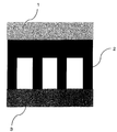
以下、図面を参照して、実施の形態に係る構造物について、図1に示すように、アスファルト層1と路盤3の間に設置され、アスファルト層1を透過した雨水を一時的に貯留しかつ排水することが可能な構造物2を例に説明する。図2は、実施の形態に係る構造物を表側から視た斜視図であり、図3は、これを裏側から視た斜視図である。図2、3に示すように、構造物2は、樹脂で形成された略平板状の部材であり、中央部4と、中央部4の周辺を取り囲む枠部6から構成されている。なお、図2に示す、構造物2の短辺長さBは、高さCの4倍以上となるように設計されている。
中央部4は、図4に示す第1ピース8を、構造物2の長手方向、短手方向にそれぞれ複数連接させて形成されている。個々の第1ピース8は、図4に示すように、六角柱状の形状を有しており、亀甲状の第1表面部8aには、長丸形状を有する第1開口部8bが六個形成されている。六個の第1開口部8bは、第1表面部8aの中央から側壁8c側に放射状に広がっており、第1表面部8aの外縁には、第1表面部8aから突出して第1リブ8dが形成されている。なお、第1リブ8dの高さは、20mm以下が好ましく、2mm以上15mm以下がより好ましい。ここで、第1表面部8aに第1リブ8dを形成することにより、耐せん断力が向上するため、たとえば、タイヤの切り替えしが行われた場合にも構造物2上のアスファルト層1がずれないようにすることができる。
また、第1ピース8の側方には、第1ピース8同士の境界を画成する側壁8cが形成され、側壁8cの下方には、雨水の通路となる第1通路部8eが形成されている。また、第1通路部8eを挟んだ位置には、第1脚部8fが側壁8cの両脇から下方に延びている。
枠部6は、図5に示す第2ピース10を、中央部4の周囲において枠状に連接させて形成されている。個々の第2ピース10は、図5に示すように、直方体状の形状を有しており、矩形状の第2表面部10aには、長丸形状を有する第2開口部10bが少なくとも一つ以上形成されている。なお、図5においては、三個の第2開口部10bが、第2表面部10aの長手方向に並んでいる場合が例として示されている。また、第2表面部10aの境界には、第2表面部10aから突出して第2リブ10dが形成されている。第2リブ10dの高さは、20mm以下が好ましく、2mm以上15mm以下がより好ましい。
また、第2ピース10の側方には、第2ピース10同士の境界を画成する側壁10cが形成され、側壁10cの下方には、雨水の通路となる第2通路部10eが形成されている。また、第2通路部10eを挟んだ位置には、第2脚部10fが側壁10cの両脇から下方に延びている。ここで、図6に示すように、連続する第2ピース10の第2脚部10fの下端は、砂利などが敷き詰められた路盤3(図1参照)とT字状に接することができるように形成されているため、路盤3に突き刺さり難い。よって、路盤3に配置された構造物2の空隙率を的確に維持することができ、雨水貯留性を損なわないようにすることができる。
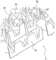
また、枠部6には、構造物2同士を連結させるための連結部が備えられている。この連結部は、図7に示すように、枠部6の外側に突出する凸部12aと、枠部6の内側に窪んだ凹部12b(図2参照)から成るものである。ここで、図8に示すように、構造物2同士を連結させる場合には、凸部12aを凹部12bの直上または直下に位置させ、構造物2を高さ方向に移動させて凸部12aを凹部12b内に嵌合させる。なお、凸部12aは、上下のいずれの方向からも凹部12b内に嵌合させることができるように、中央部が膨らんだ太鼓型の形状を有している。
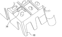
また、枠部6の四隅には、図9に示すように、第2表面部10aから突出する断面略L字状のリブ14が設けられている。構造物2は、製造時に積み重ねられるため、第2表面部10aにリブ14を設けることにより、構造物2を積み重ねやすくすることができる。また、搬送時においても、第2ピース10の第2脚部10fがリブ14に引っ掛かるため荷崩れを防止することができる。なお、リブ14の高さは、2mm以上50mm以下であることが好ましく、4mm以上30mm以下がより好ましい。
ここで、この構造物2は、第1表面部8aの面積に対する第1開口部8bの面積(以下、開口率という。)が18%以上であるのが好ましく、20%以上50%以下であればより好ましい。本実施の形態の構造物2は、開口率が18%以上となるように設計されている。このように、開口率を18%以上とすることにより、第1表面部8aの透水性を向上させることができる。開口率と透水性の関係については、実施例3で詳しく説明する。
また、構造物2は、構造物2の体積に対して、第1開口部8b、第2開口部10b、第1通路部8e、および第2通路部10eを含む空間の体積の割合(以下、空隙率という。)が80%以上であるのが好ましく、82%以上96%以下であればより好ましい。本実施の形態の構造物2の空隙率は80%以上となるように設計されている。なお、構造物2の体積とは、図2に示される、長辺長さA×短辺長さB×高さCで表される体積である。また、上述の空間とは、樹脂が存在しない部分を指している。
このように空隙率を大きくした場合、樹脂の占める割合が低減され、図6に示すように、構造物2の裏面に広い空間が形成される。よって、構造物2の空隙率を80%以上とすることにより、アスファルト層1(図1参照)を透過した雨水を一時的に貯留する貯留力を向上させることができる。また、第1通路部8e、第2通路部10eの開口面積を大きくすることにより、構造物2に貯留された雨水を的確に水平方向に流し、排水することができる。
また、図10に示すように、第1開口部8b、および第2開口部10bは、一方向に延び、両端が半円状に形成された長丸形状を有していることが好ましい。なお、第1開口部8b、および第2開口部10bの形状は必ずしも長丸形状に限定されず、丸形状、三角形、四角形状等であってもよい。ここで、第1開口部8b、第2開口部10bの最小幅を構成する平行部分の幅Hは、6mm以上8mm以下であるのが好ましい。これにより、施工時にアスファルトが開口部を通過することを抑制することができる。なお、開口部の幅Hとアスファルト層1の骨材の関係については、実施例1で詳しく説明する。
また、構造物2を構成する樹脂は、熱可塑性樹脂または熱硬化性樹脂であり、各種繊維、鉱物、金属などの添加剤を含有しても良い。ただし、構造物としての特性を満足すれば、特に樹脂、添加剤の種類は限定されるものではない。具体的には、構造物2を構成する樹脂は、たとえば、ポリプロピレン(PP)、ポリカーボネード(PC)、およびガラス繊維(GF)を含むポリプロピレン(PP)、ガラス繊維(GF)を含むポリカーボネード(PC)によって形成されていてもよい。このため、アスファルト層1が熱せられた状態で荷重が掛けられても耐えうる耐熱性、高強度を発揮することができる。
この実施の形態に係る発明によれば、表面の開口率が高くかつ全体の空隙率が高い構造物2をアスファルト層1と路盤3の間に設置することにより(図1参照)、アスファルト層1を透過した雨水を的確に排水し、路上に冠水が生じることを的確に抑制することができる。また、構造物2は、雨水貯留施設のように大がかりでなく、厚さも薄いため、地表面の近くに配置することができる。したがって、地下水位が浅い場所においても浸透施設として機能し、的確に冠水を防止することができる。また、構造物2は、高い空隙率を有するため、豪雨などの一度に排水ができない場合には、一時的に構造物2内に雨水を貯留することができ、排水量を調整することができる。
また、構造物2は、路盤3上に積み重ねず1段のみを配置して使用する場合において、容易に施工することができる。ただし、1段のみの配置に限定されるものではなく、2段以上配置して使用することも可能である。
次に、本実施の形態に係る構造物2に係る実施例について説明する。
[1]実施例1(開口部の大きさ)
実施例1においては、第1開口部8b、および第2開口部10bの大きさをどの程度にするのが適当であるかについて実験を行った。実験においては、まず、図11(a)に示すような、穴あき角板20を複数用意した。ここで、複数の穴あき角板20の内訳としては、穴の半径Rが2.5mmのもの、穴の半径Rが3.5mmのもの、穴の半径Rが4mmのもの、穴の半径Rが5mmのものをそれぞれ用意した。
[1]実施例1(開口部の大きさ)
実施例1においては、第1開口部8b、および第2開口部10bの大きさをどの程度にするのが適当であるかについて実験を行った。実験においては、まず、図11(a)に示すような、穴あき角板20を複数用意した。ここで、複数の穴あき角板20の内訳としては、穴の半径Rが2.5mmのもの、穴の半径Rが3.5mmのもの、穴の半径Rが4mmのもの、穴の半径Rが5mmのものをそれぞれ用意した。
次に、図11(b)に示すように、穴あき角板20をアスファルト層1と白紙21で挟んで、穴あき角板20を透過したアスファルト痕を観察することにより行った。
図12は、穴の半径Rの異なる穴あき角板20を使用した場合において、白紙21に残されたアスファルト痕を示す図である。図12(a)は、穴の半径Rが2.5mmの穴あき角板20を使用した場合のアスファルト痕を示しており、図12(b)は、穴の半径Rが3.5mmの穴あき角板20を使用した場合のアスファルト痕を示している。同様に、図12(c)は、穴の半径Rが4mmの穴あき角板20を使用した場合のアスファルト痕を示しており、図12(d)は、穴の半径Rが5mmの穴あき角板20を使用した場合のアスファルト痕を示している。
図12は、穴の半径Rの異なる穴あき角板20を使用した場合において、白紙21に残されたアスファルト痕を示す図である。図12(a)は、穴の半径Rが2.5mmの穴あき角板20を使用した場合のアスファルト痕を示しており、図12(b)は、穴の半径Rが3.5mmの穴あき角板20を使用した場合のアスファルト痕を示している。同様に、図12(c)は、穴の半径Rが4mmの穴あき角板20を使用した場合のアスファルト痕を示しており、図12(d)は、穴の半径Rが5mmの穴あき角板20を使用した場合のアスファルト痕を示している。
図12によれば、穴あき角板20の穴の半径Rが大きくなるほどアスファルト痕が明瞭になることがわかる。ここで、図12(a)のように、穴の半径Rを2.5mmとした場合、アスファルトの通過はし難くなるが、穴が小さくなる分、穴あき角板20成形が難しくなるという問題がある。また、図12(d)のように、穴の半径Rを5mmとした場合、アスファルトの骨材が穴を通過すると共に、空隙率が低下する。かかる問題点を考慮すると、穴の半径Rは、3mm以上4.5mm以下程度であることが好ましい。
[2]実施例2(穴の形状)
実施例2においては、第1開口部8b、および第2開口部10bをいかなる形状にするのが妥当であるかについて検討を行った。
実施例2においては、第1開口部8b、および第2開口部10bをいかなる形状にするのが妥当であるかについて検討を行った。
ここで、開口部の形状としては、図13(a)に示すように、丸形状とすること、図13(b)に示すように、三角形状とすること、図13(c)に示すように、長丸形状とすることが考えられる。
この点、図13(a)に示すように開口部を丸形状とした場合、および図13(b)に示すように開口部を三角形状とした場合には、図13(c)に示すように開口部を長丸形状とした場合に比べて、多くの開口部を形成する必要があるため、成形がし難く、金型を作成するのも困難となる。また、開口部間にウェルドが形成され、この部分の強度が弱くなるという問題がある。かかる点を考慮した結果、本発明の構造物2においては、図13(c)に示すように開口部を長丸形状とすることにした。
[3]実施例3(開口率と透水性の関係)
実施例3においては、構造物2の開口率と透水性の関係について実験を行った。実験は、図14に示すように、穴あき角板20の上にアスファルト層1を載置し、周囲を透明塩ビ板22で囲った。そして、アスファルト層1の上に3000ccの水23が収納された水槽24を載置した。
実施例3においては、構造物2の開口率と透水性の関係について実験を行った。実験は、図14に示すように、穴あき角板20の上にアスファルト層1を載置し、周囲を透明塩ビ板22で囲った。そして、アスファルト層1の上に3000ccの水23が収納された水槽24を載置した。
次に、水槽のコック24aを開いてアスファルト層1に水23を流すと、徐々にアスファルト層1上の水溜りの水嵩26が増し、最高水位に達する。その後、水23は次第にアスファルト層1、穴あき角板20を透過してアスファルト層1上の水溜りは消滅する。
なお、本実験においては、穴数(開口率)の異なる穴あき角板20を複数用意し、それぞれの水溜り量を観察することにより、透水性に支障を来たさない開口率を見極めた。ここで、本実験に用いた穴あき角板20の開口率と水溜り量の関係について、表1、および図15のグラフに示す。なお、開口率が100%の場合とは、穴あき角板20を用いない場合の結果である。

この表1、および図15を開口率の大きい順に観察すると、開口率が100%、50%、30%の場合においては、いずれも水溜り量が同一の754(cc)となる。開口率が20%になると水溜り量が微増して765(cc)となる。開口率が15%になると水溜り量が866(cc)となり、15%よりも小さくなると、水溜り量は急増する。
このような実験結果を考慮し、本発明の構造物2においては、第1表面部8aの開口率が18%以上となるように設計した。
このような実験結果を考慮し、本発明の構造物2においては、第1表面部8aの開口率が18%以上となるように設計した。
[4]実施例4(第1ピース8の基本形状)
実施例4においては、構造物2の中央部4を構成する第1ピース8の基本形状について、形状の異なる複数のピースを用意し、比較検討を行った。ここで、検討に用いたピースは、図16に示す、A、B、C、D、Eの五つのモデルである。モデルAは、本発明に係る第1ピース8に近似するモデルであり、それ以外は比較例として用いるピースである。
ここで、実施例4においては、表2に示すように、開口率と強度についての検討を行った。
実施例4においては、構造物2の中央部4を構成する第1ピース8の基本形状について、形状の異なる複数のピースを用意し、比較検討を行った。ここで、検討に用いたピースは、図16に示す、A、B、C、D、Eの五つのモデルである。モデルAは、本発明に係る第1ピース8に近似するモデルであり、それ以外は比較例として用いるピースである。
ここで、実施例4においては、表2に示すように、開口率と強度についての検討を行った。

開口率については、各々のピースの開口率が18%以上であるか否かを判定した。判定結果は、モデルDのピース以外はすべて判定基準を満足する結果となった。
強度については、CAE解析によるシミュレーションを3パターン検討した。まず、表2の強度(1)は、夏の施工時にアスファルトフィニッシャーが構造物2上を走行した場合を想定している。この場合、構造物2の温度は40℃程度になる上、構造物2には、195kPa程度の面圧が掛かることになる。一方で、各々のピースを構成する材料自体の許容応力度は45MPaが許容応力度となる。解析の結果、強度(1)の条件において、負荷を許容応力度である45MPa以下に維持できるのは、モデルA、B、D、Eのみであった。
強度については、CAE解析によるシミュレーションを3パターン検討した。まず、表2の強度(1)は、夏の施工時にアスファルトフィニッシャーが構造物2上を走行した場合を想定している。この場合、構造物2の温度は40℃程度になる上、構造物2には、195kPa程度の面圧が掛かることになる。一方で、各々のピースを構成する材料自体の許容応力度は45MPaが許容応力度となる。解析の結果、強度(1)の条件において、負荷を許容応力度である45MPa以下に維持できるのは、モデルA、B、D、Eのみであった。
表2の強度(2)は、夏の施工時にロードローラーでアスファルト層1を圧し固めた場合を想定している。この場合、構造物2の温度は120℃程度になる上、アスファルト層1には、133kPa程度の面圧が掛かることになる。一方で、各々のピースを構成する材料自体の許容応力度は16MPaが許容応力度となる。解析の結果、強度(2)の条件において、負荷を許容応力度である16MPa以下に維持できるのは、モデルA、D、Eのみであった。
表2の強度(3)は、施工後、夏季に25トントラックがアスファルト層1の上を走行した場合を想定している。この場合、構造物2の温度は60℃程度になる上、アスファルト層1には、472kPa程度の面圧が掛かることになる。一方で、各々のピースを構成する材料自体の間欠応力度は20MPaとなる。解析の結果、強度(3)の条件において、負荷を間欠応力度である20MPa以下に維持できるのは、モデルAのみであった。
以上説明したように、開口率と強度について行なった検討において、すべての場合に要件を満足するのは、本発明の構造物2に近似するモデルAのみであった。
なお、上述の実施の形態においては、アスファルト層1と路盤3の間に設置する構造物2を例として説明しているが、構造物2は、必ずしもアスファルト層の下に敷くものに限定されない。
なお、上述の実施の形態においては、アスファルト層1と路盤3の間に設置する構造物2を例として説明しているが、構造物2は、必ずしもアスファルト層の下に敷くものに限定されない。
1 アスファルト層
2 構造物
3 路盤
4 中央部
6 枠部
8 第1ピース
8a 第1表面部
8b 第1開口部
8c 第1側壁
8d 第1リブ
8e 第1通路部
8f 第1脚部
10 第2ピース
10a 第2表面部
10b 第2開口部
10c 第2側壁
10d 第2リブ
10e 第2通路部
10f 第2脚部
12a 凸部
12b 凹部
14 リブ
20 角板
21 白紙
22 透明塩ビ板
23 水
24 水槽
24a コック
26 水嵩
A 長辺長さ
B 短辺長さ
C 高さ
H 幅
R 半径
2 構造物
3 路盤
4 中央部
6 枠部
8 第1ピース
8a 第1表面部
8b 第1開口部
8c 第1側壁
8d 第1リブ
8e 第1通路部
8f 第1脚部
10 第2ピース
10a 第2表面部
10b 第2開口部
10c 第2側壁
10d 第2リブ
10e 第2通路部
10f 第2脚部
12a 凸部
12b 凹部
14 リブ
20 角板
21 白紙
22 透明塩ビ板
23 水
24 水槽
24a コック
26 水嵩
A 長辺長さ
B 短辺長さ
C 高さ
H 幅
R 半径
Claims (6)
- 第1ピースを複数連接させて成る中央部と、第2ピースを複数連接させて成る枠部とによって構成される略平板状の構造物であって、
前記第1ピースは、
複数の第1開口部を有する第1表面部と
側方に形成された第1通路部を挟んだ位置に設けられた第1脚部とを備え、
前記第2ピースは、
少なくとも一つの第2開口部を有する第2表面部と
側方に形成された第2通路部を挟んだ位置に設けられた第2脚部とを備え、
前記第1表面部の面積に対する前記第1開口部の面積である開口率が18%以上であり、
かつ、略平板状の該構造物の体積に対して、前記第1開口部、前記第2開口部、前記第1通路部、および前記第2通路部を含む空間の体積の割合である空隙率が80%以上であることを特徴とする構造物。 - 前記第1ピースは、六角柱状の形状を有し、
前記第2ピースは、四角柱状の形状を有することを特徴とする請求項1記載の構造物。 - 前記第1開口部、および前記第2開口部の幅は、6mm以上8mm以下であることを特徴とする請求項1または2記載の構造物。
- 前記第1表面部同士の境界、前記第2表面部同士の境界、前記第1表面部と前記第2表面部同士の境界の少なくとも一つには、高さ20mm以下のリブが形成されていることを特徴とする請求項1~3の何れか一項に記載の構造物。
- 前記第2ピースには、該構造物同士を嵌合する嵌合部が形成され、
前記嵌合部は、一対の凹部と凸部を含み、
前記凸部は、嵌合方向の中央部が膨らんだ太鼓型を有することを特徴とする請求項4記載の構造物。 - 前記第1ピースおよび前記第2ピースは、樹脂で形成されていることを特徴とする請求項1~5の何れか一項に記載の構造物。
Priority Applications (2)
| Application Number | Priority Date | Filing Date | Title |
|---|---|---|---|
| JP2019502498A JP6754488B2 (ja) | 2017-02-28 | 2018-01-17 | 構造物 |
| MYPI2019004803A MY193843A (en) | 2017-02-28 | 2018-01-17 | Structure |
Applications Claiming Priority (2)
| Application Number | Priority Date | Filing Date | Title |
|---|---|---|---|
| JP2017036441 | 2017-02-28 | ||
| JP2017-036441 | 2017-02-28 |
Publications (1)
| Publication Number | Publication Date |
|---|---|
| WO2018159128A1 true WO2018159128A1 (ja) | 2018-09-07 |
Family
ID=63371382
Family Applications (1)
| Application Number | Title | Priority Date | Filing Date |
|---|---|---|---|
| PCT/JP2018/001184 Ceased WO2018159128A1 (ja) | 2017-02-28 | 2018-01-17 | 構造物 |
Country Status (4)
| Country | Link |
|---|---|
| JP (1) | JP6754488B2 (ja) |
| MY (1) | MY193843A (ja) |
| TW (1) | TWI743298B (ja) |
| WO (1) | WO2018159128A1 (ja) |
Citations (2)
| Publication number | Priority date | Publication date | Assignee | Title |
|---|---|---|---|---|
| JP2004019426A (ja) * | 2002-06-17 | 2004-01-22 | Masanobu Sugie | 地下貯水槽の中込ブロック組立構造、同槽の単層構造および地下貯水槽 |
| JP2007332607A (ja) * | 2006-06-13 | 2007-12-27 | Bridgestone Corp | 雨水貯留浸透槽用の構成部材及び雨水貯留浸透槽 |
Family Cites Families (1)
| Publication number | Priority date | Publication date | Assignee | Title |
|---|---|---|---|---|
| TWM342381U (en) * | 2008-01-29 | 2008-10-11 | Yong-Zhang Wen | Drainage board capable of extending infinitely |
-
2018
- 2018-01-17 JP JP2019502498A patent/JP6754488B2/ja active Active
- 2018-01-17 WO PCT/JP2018/001184 patent/WO2018159128A1/ja not_active Ceased
- 2018-01-17 MY MYPI2019004803A patent/MY193843A/en unknown
- 2018-01-26 TW TW107102905A patent/TWI743298B/zh active
Patent Citations (2)
| Publication number | Priority date | Publication date | Assignee | Title |
|---|---|---|---|---|
| JP2004019426A (ja) * | 2002-06-17 | 2004-01-22 | Masanobu Sugie | 地下貯水槽の中込ブロック組立構造、同槽の単層構造および地下貯水槽 |
| JP2007332607A (ja) * | 2006-06-13 | 2007-12-27 | Bridgestone Corp | 雨水貯留浸透槽用の構成部材及び雨水貯留浸透槽 |
Also Published As
| Publication number | Publication date |
|---|---|
| JPWO2018159128A1 (ja) | 2019-11-07 |
| TWI743298B (zh) | 2021-10-21 |
| JP6754488B2 (ja) | 2020-09-09 |
| MY193843A (en) | 2022-10-28 |
| TW201833415A (zh) | 2018-09-16 |
Similar Documents
| Publication | Publication Date | Title |
|---|---|---|
| KR101227275B1 (ko) | 도로포장용 블록, 그것을 이용한 도로포장구조 및 그 시공방법 | |
| JP5700888B1 (ja) | 路面用排水部材及び路面用排水部材を敷設する方法 | |
| JP5845132B2 (ja) | 排水側溝 | |
| KR101641050B1 (ko) | 바닥용 배수판 | |
| KR101665326B1 (ko) | 직투수공을 갖는 블록 및 이를 이용한 침투 및 저류 포장시스템 | |
| JP6754488B2 (ja) | 構造物 | |
| JP2021088911A (ja) | 透水性舗装部材用の嵌合部材 | |
| CN215252411U (zh) | 公路路基边坡排水结构 | |
| KR101976073B1 (ko) | 배수 및 저류 성능이 우수한 블록 및 블록 세트 | |
| KR101201570B1 (ko) | 견고한 연결구조를 가지는 토양 유지용 격자판 및 그 연결구조 | |
| KR101019562B1 (ko) | 보도블록 및 보차도 경계석을 포함하는 도로의 시공 구조 및 시공 방법 | |
| KR101770268B1 (ko) | 우수 침투 및 저류를 위한 저류 단위블록, 저류조 구조물 및 그 시공 방법 | |
| KR20170143279A (ko) | 투수기능을 갖는 적층식 블록조립체와 이를 이용한 투수시스템 및 투수시스템 시공방법 | |
| KR101947257B1 (ko) | Lid 구조물 | |
| JP6614655B2 (ja) | 自由勾配側溝を使用した自転車通行帯つき新道路形成工法 | |
| JP2016079592A (ja) | 舗装構造 | |
| KR100969813B1 (ko) | 배수기능이 향상된 그레이팅 및 제조방법 | |
| KR101859056B1 (ko) | 우수 침투 및 저류를 위한 저류 단위 블록, 저류조 구조물 및 그 시공방법 | |
| KR101052088B1 (ko) | 연약지반용 수평 드레인보드 | |
| JP3943114B2 (ja) | 水路の敷設工法 | |
| KR101755590B1 (ko) | 도로 및 토목공사용 모듈형 조립식 맹암거 | |
| JP6637309B2 (ja) | 集水機能を有するコンクリート二次成形品集水機能を有するコンクリート二次成形品を多数用いて構成された道路構造物集水機能を有するコンクリート二次成形品の成形方法 | |
| JP2013217144A (ja) | 噴砂防止構造 | |
| KR101843799B1 (ko) | 수평배수재 | |
| JP2005226396A (ja) | 一体型暗渠ブロック及び道路側縁の排水構造 |
Legal Events
| Date | Code | Title | Description |
|---|---|---|---|
| 121 | Ep: the epo has been informed by wipo that ep was designated in this application |
Ref document number: 18760537 Country of ref document: EP Kind code of ref document: A1 |
|
| ENP | Entry into the national phase |
Ref document number: 2019502498 Country of ref document: JP Kind code of ref document: A |
|
| NENP | Non-entry into the national phase |
Ref country code: DE |
|
| 122 | Ep: pct application non-entry in european phase |
Ref document number: 18760537 Country of ref document: EP Kind code of ref document: A1 |