WO2018155458A1 - 遠心回転機械 - Google Patents
遠心回転機械 Download PDFInfo
- Publication number
- WO2018155458A1 WO2018155458A1 PCT/JP2018/006083 JP2018006083W WO2018155458A1 WO 2018155458 A1 WO2018155458 A1 WO 2018155458A1 JP 2018006083 W JP2018006083 W JP 2018006083W WO 2018155458 A1 WO2018155458 A1 WO 2018155458A1
- Authority
- WO
- WIPO (PCT)
- Prior art keywords
- working fluid
- flow path
- impeller
- axial direction
- return
- Prior art date
Links
Images


Classifications
-
- F—MECHANICAL ENGINEERING; LIGHTING; HEATING; WEAPONS; BLASTING
- F04—POSITIVE - DISPLACEMENT MACHINES FOR LIQUIDS; PUMPS FOR LIQUIDS OR ELASTIC FLUIDS
- F04D—NON-POSITIVE-DISPLACEMENT PUMPS
- F04D17/00—Radial-flow pumps, e.g. centrifugal pumps; Helico-centrifugal pumps
- F04D17/08—Centrifugal pumps
- F04D17/10—Centrifugal pumps for compressing or evacuating
- F04D17/12—Multi-stage pumps
- F04D17/122—Multi-stage pumps the individual rotor discs being, one for each stage, on a common shaft and axially spaced, e.g. conventional centrifugal multi- stage compressors
-
- F—MECHANICAL ENGINEERING; LIGHTING; HEATING; WEAPONS; BLASTING
- F04—POSITIVE - DISPLACEMENT MACHINES FOR LIQUIDS; PUMPS FOR LIQUIDS OR ELASTIC FLUIDS
- F04D—NON-POSITIVE-DISPLACEMENT PUMPS
- F04D29/00—Details, component parts, or accessories
- F04D29/40—Casings; Connections of working fluid
- F04D29/42—Casings; Connections of working fluid for radial or helico-centrifugal pumps
- F04D29/44—Fluid-guiding means, e.g. diffusers
-
- F—MECHANICAL ENGINEERING; LIGHTING; HEATING; WEAPONS; BLASTING
- F04—POSITIVE - DISPLACEMENT MACHINES FOR LIQUIDS; PUMPS FOR LIQUIDS OR ELASTIC FLUIDS
- F04D—NON-POSITIVE-DISPLACEMENT PUMPS
- F04D29/00—Details, component parts, or accessories
- F04D29/18—Rotors
- F04D29/22—Rotors specially for centrifugal pumps
-
- F—MECHANICAL ENGINEERING; LIGHTING; HEATING; WEAPONS; BLASTING
- F04—POSITIVE - DISPLACEMENT MACHINES FOR LIQUIDS; PUMPS FOR LIQUIDS OR ELASTIC FLUIDS
- F04D—NON-POSITIVE-DISPLACEMENT PUMPS
- F04D29/00—Details, component parts, or accessories
- F04D29/40—Casings; Connections of working fluid
- F04D29/42—Casings; Connections of working fluid for radial or helico-centrifugal pumps
- F04D29/44—Fluid-guiding means, e.g. diffusers
- F04D29/441—Fluid-guiding means, e.g. diffusers especially adapted for elastic fluid pumps
- F04D29/444—Bladed diffusers
-
- F—MECHANICAL ENGINEERING; LIGHTING; HEATING; WEAPONS; BLASTING
- F05—INDEXING SCHEMES RELATING TO ENGINES OR PUMPS IN VARIOUS SUBCLASSES OF CLASSES F01-F04
- F05D—INDEXING SCHEME FOR ASPECTS RELATING TO NON-POSITIVE-DISPLACEMENT MACHINES OR ENGINES, GAS-TURBINES OR JET-PROPULSION PLANTS
- F05D2240/00—Components
- F05D2240/10—Stators
- F05D2240/12—Fluid guiding means, e.g. vanes
- F05D2240/122—Fluid guiding means, e.g. vanes related to the trailing edge of a stator vane
Definitions
- the present invention relates to a centrifugal rotating machine. This application claims priority on February 22, 2017 based on Japanese Patent Application No. 2017-031196 filed in Japan, the contents of which are incorporated herein by reference.
- a rotary machine such as a centrifugal compressor mainly includes an impeller that rotates about an axis, and a casing that forms a flow path of a working fluid between the impeller and the outer periphery of the impeller.
- the flow path of each stage includes a diffuser flow path, a return bend portion, and a guide flow path.
- the diffuser flow path is provided on the radially outer side of the impeller, extends from the impeller to the radially outer side of the axis, and guides the working fluid discharged from the impeller outlet to the radially outer side.
- the return bend portion is continuously provided on the radially outer side of the diffuser flow path, and reverses the direction of the working fluid flow from the radially outer side to the inner side.
- the guide channel is provided on the downstream side of the return bend portion, and guides the working fluid to the inlet of the rear impeller.
- the working fluid discharged from the outlet of the impeller has a swirl direction component due to rotation around the axis of the impeller.
- the working fluid reaches the impeller on the rear stage through the diffuser flow path, the return bend section, and the guide flow path with the swirling component remaining, it adversely affects the compression process for the working fluid in the rear impeller, and the rotating machine It may lead to a decrease in efficiency.
- Patent Documents 1 and 2 disclose a configuration in which return vanes (guide vanes and vanes) for rectification are provided in the guide channel. By providing the return vane in the guide flow path, components in the swirl direction of the working fluid discharged from the impeller outlet and passed through the diffuser flow path and the return bend are removed, and a decrease in the efficiency of the rotating machine is suppressed.
- this invention is made
- the present invention employs the following means in order to solve the above problems.
- an impeller that is provided in a plurality of stages along the axial direction and discharges the working fluid sucked from the first side in the axial direction to the outside in the radial direction of the axial line;
- the downstream side impeller which is provided so as to surround the impeller and is discharged from the upstream side impeller located on the first axial side, is located on the second side in the axial direction.
- a casing that forms a flow path leading to The flow path is connected to a return bend portion that guides the working fluid that is discharged radially outward from the impeller on the upstream side by inverting radially inward, and downstream of the return bend portion,
- a guide channel that guides the working fluid radially inward and guides the working fluid to the impeller on the downstream side.
- Centrifugal rotating machines are provided in the guide channel for guiding the working fluid to at least one of the impellers provided in a plurality of stages, and a plurality of centrifugal rotating machines are provided at intervals in the circumferential direction around the axis.
- return vanes In the return vane, the second edge on the second side in the axial direction is in the radial direction with respect to the rear edge located on the radially inner side than the first end on the first side in the axial direction. It is formed to be located inside.
- the second end portion of the trailing edge located on the radially inner side in the return vane is located on the radially inner side than the first end portion.
- the return vane has a length along the flow direction of the working fluid that is longer than the first side in the axial direction.
- the second side in the axial direction may be formed to be long.
- the length of the return vane along the flow direction of the working fluid is set larger on the second side (downstream side) than on the first side (upstream side) in the axial direction.
- the length of the working fluid flowing along the return vane can be increased.
- the suppression effect of the swirling component of the working fluid can be enhanced on the second side in the axial direction.
- the trailing edge of the return vane gradually increases from the first end toward the second end. It may extend radially inward.
- the trailing edge of the return vane is radially between the first end and the second end. You may make it bend and form so that it may become convex toward the inner side or concave toward the radial direction outer side.
- the swirl component of the working fluid applied by the return vane between the first end on the first side in the axial direction and the second end on the second side in the axial direction can be increased or decreased.
- the effect of suppressing the swirling component of the working fluid can be optimized.
- the trailing edge of the return vane extends from the first end to the guide channel in the axial direction.
- the second end portion may be located on the radially inner side with respect to the normal extending perpendicular to the upstream side wall surface on the first side.
- the second end portion is located radially inward from the first end portion at the trailing edge of the return vane.
- the return vane is formed such that a front edge located radially outside is linearly formed along the axis. You may be allowed to.
- leading edge in a straight line, the leading edge can be easily processed.
- the return vane is longer in the axial direction at the rear edge than at the front edge located radially outward. You may make it large.
- the swirl component remaining in the working fluid that has passed through the return vane can be suppressed, and the efficiency of the rotating machine can be improved.
- FIG. 1 It is a schematic diagram which shows the structure of the centrifugal compressor which concerns on each embodiment of this invention. It is a figure which shows the structure of the guide flow path of the centrifugal compressor which concerns on 1st embodiment of this invention, and is the figure which looked at the guide flow path from the direction which cross
- FIG. 1 is a mimetic diagram showing the composition of the centrifugal compressor concerning each embodiment of the present invention.
- FIG. 2 is a view showing the configuration of the guide flow path of the centrifugal compressor according to the first embodiment of the present invention, and is a view of the guide flow path as viewed from the direction intersecting the axial direction.
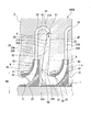
- FIG. 3 is an enlarged cross-sectional view of a main part of the centrifugal compressor.
- FIG. 4 is a diagram showing a distribution of swirl components at the guide channel outlet in the axial direction of the guide channel.
- the centrifugal compressor 100 includes a rotor 1, a casing 3, and a plurality of impellers 4 provided on the rotor 1.
- the rotor 1 extends so as to penetrate the inside of the casing 3 along the axis O.
- Journal bearings 5 and thrust bearings 6 are provided at both ends of the casing 3 in the direction of the axis O, respectively.
- the rotor 1 is supported by the journal bearing 5 and the thrust bearing 6 so as to be rotatable around the axis O.
- the casing 3 has a cylindrical shape extending substantially along the axis O. Inside the casing 3, an internal space that repeats the diameter reduction and diameter expansion is formed.
- the casing 3 is provided so as to cover the periphery of the rotor 1 and the plurality of stages of impellers 4 by accommodating the plurality of impellers 4 in the internal space, and forms a flow path 2 between the rotor 3 and the casing 3.
- an intake port 7 for taking in air as the working fluid G from the outside and feeding it into the flow path 2 is provided on the first side of the casing 3 in the direction of the axis O. Further, an exhaust port 8 through which the working fluid G compressed in the casing 3 is exhausted from the flow path 2 is provided on the second side of the casing 3 in the direction of the axis O.
- the first side where the intake port 7 is located is called the upstream side
- the second side where the exhaust port 8 is located is called the downstream side.
- the impeller 4 is provided in the rotor 1 with a plurality of stages, for example, six stages in the example of FIG.
- Each impeller 4 discharges the working fluid G sucked from the first side in the axis O direction to the outside in the radial direction Dd of the axis O.
- each impeller 4 includes a disk 41, a blade 42, and a shroud 43.
- the disk 41 has a substantially circular shape when viewed from the direction of the axis O.
- the disk 41 When viewed from the direction intersecting the axis O, the disk 41 has a radial dimension from the first side (left side in FIG. 2) to the second side (right side in FIG. 2) in the axis O direction. Is formed so as to expand gradually, and has a generally conical shape.
- the blades 42 are provided on a conical surface facing the upstream side among both surfaces of the disk 41 in the direction of the axis O.
- a plurality of blades 42 are arranged radially about the axis O toward the outside in the radial direction Dd. More specifically, the blades 42 are formed by thin plates that are erected from the upstream surface of the disk 41 toward the upstream side. Further, although not shown in detail, the plurality of blades 42 are curved so as to be directed from one side to the other side in the circumferential direction when viewed from the direction of the axis O.
- the shroud 43 is provided on the upstream edge of the blade 42 so as to cover the plurality of blades 42 from the upstream side.
- the plurality of blades 42 are generally sandwiched by the shroud 43 and the disk 41 from the direction of the axis O.
- a space is formed between the shroud 43, the disk 41, and a pair of adjacent blades 42. This space forms part of the flow path 2 (compression flow path 22) described later.
- the flow path 2 is a space that communicates between the impeller 4 configured as described above and the internal space of the casing 3. In the present embodiment, description will be made assuming that one flow path 2 is formed for each impeller 4 (for each compression stage).
- the flow path 2 guides the working fluid G discharged from the upstream impeller 4 located on the first side in the axis O direction to the downstream impeller 4 located on the second side in the axis O direction. That is, in the centrifugal compressor 100, five flow paths 2 continuous from the upstream side toward the downstream side are formed corresponding to the five impellers 4 excluding the last stage impeller 4.
- Each flow path 2 has a suction flow path 21, a compression flow path 22, a diffuser flow path 23, a return bend portion 24, and a guide flow path 25.
- the suction flow path 21 is substantially directly connected to the intake port 7. External air is taken into the flow path 2 as the working fluid G by the suction flow path 21. More specifically, the suction flow path 21 is gradually curved from the direction of the axis O toward the outside of the radial direction Dd as it goes from the upstream side to the downstream side.
- the suction flow path 21 in the impeller 4 after the second stage communicates with the downstream end of the guide flow path 25 (described later) in the flow path 2 in the previous stage (first stage). That is, the flow direction of the working fluid G that has passed through the guide flow path 25 is changed so as to face the downstream side along the axis O in the same manner as described above.
- the compression flow path 22 is a flow path surrounded by the upstream surface of the disk 41, the downstream surface of the shroud 43, and a pair of blades 42 adjacent in the circumferential direction. More specifically, the cross-sectional area of the compression flow path 22 gradually decreases from the inner side to the outer side in the radial direction Dd. Thereby, the working fluid G which circulates in the compression flow path 22 in the state where the impeller 4 is rotating is gradually compressed to become a high-pressure fluid.
- the diffuser flow path 23 is surrounded by a diffuser front wall 23A, which is a part of an inner peripheral wall forming the internal space of the casing 3, and a diffuser rear wall 23B of the partition wall member 31, so that the inner side in the radial direction Dd of the axis O It is the flow path extended toward the outside from.
- the inner end of the diffuser flow path 23 in the radial direction Dd communicates with the outer end of the compression flow path 22 in the radial direction Dd.
- the partition wall member 31 is a member that is provided integrally on the inner peripheral side of the casing 3 so as to separate the plurality of impellers 4 adjacent in the axis O direction. Further, as viewed from the partition wall member 31, an extending portion 32 that is provided integrally with the casing 3 is provided on the upstream side of the diffuser flow path 23 and the impeller 4. The extending portion 32 is a wall portion extending from the inner peripheral surface (not shown) of the casing 3 toward the inside in the radial direction Dd.
- the return bend portion 24 is a curved flow path surrounded by the reversal wall 33 of the casing 3 and the outer peripheral wall 31 ⁇ / b> A of the partition wall member 31.
- One end side (upstream side) of the return bend portion 24 communicates with the diffuser flow path 23, and the other end side (downstream side) communicates with the guide flow path 25.
- the return bend portion 24 is discharged from the upstream impeller 4 toward the outside in the radial direction Dd, reverses the flow direction of the working fluid G through the diffuser flow path 23, and guides it to the inside in the radial direction Dd.
- the guide channel 25 is a channel surrounded by the side wall 31B facing the downstream side in the partition member 31 in the casing 3 and the side wall 32A facing the upstream side in the extending portion 32.
- the side wall 31 ⁇ / b> B forms an upstream side wall surface on the first side in the direction of the axis O in the guide channel 25.
- the outer end of the guide channel 25 in the radial direction Dd is connected to the downstream side of the return bend 24.
- the inner end of the guide channel 25 in the radial direction Dd communicates with the suction channel 21 in the downstream channel 2 as described above.
- the guide channel 25 guides the working fluid G that has passed through the return bend portion 24 to the inner side in the radial direction Dd and guides it to the impeller 4 on the downstream side.
- the centrifugal compressor 100 includes a return vane 50 in the guide channel 25. As shown in FIG. 3, a plurality of return vanes 50 are provided at intervals around the axis O in the circumferential direction. The plurality of return vanes 50 are arranged radially around the axis O in the guide channel 25. Specifically, each return vane 50 is formed of a plate material extending from the side wall 31 ⁇ / b> B of the partition wall member 31 toward the side wall 32 ⁇ / b> A of the extending portion 32.
- Each return vane 50 has a radial intermediate portion 53 on one side in the rotational direction of the impeller 4 with respect to a front edge 51 located outside the radial direction Dd and a rear edge 52 located inside the radial direction Dd. It has a curved shape that bulges out. Each return vane 50 is formed such that the trailing edge 52 extends toward the axis O (center of the rotor 1) in the radial direction Dd.
- Each return vane 50 has a front edge 51 positioned outside the radial direction Dd perpendicular to the flow direction F of the working fluid flowing in the guide flow path 25, that is, along the axis O (in this embodiment). , In parallel with the axis O).
- the return vane 50 has a second edge 52b on the second side in the direction of the axis O rather than the first end 52a on the first side in the direction of the axis O of the rear edge 52 located inside the radial direction Dd. And is formed so as to be located inside the radial direction Dd. Specifically, in the rear edge 52 of the return vane 50, the second end 52b is located on the inner side in the radial direction Dd from the normal V extending perpendicularly to the side wall 31B from the first end 52a. Further, the rear edge 52 of the return vane 50 extends linearly inwardly in the radial direction Dd from the first end 52a toward the second end 52b. Thus, the return vane 50 has a length from the front edge 51 to the rear edge 52 along the flow direction of the working fluid G that is longer on the second side in the axis O direction than on the first side in the axis O direction. It is formed to become.
- the return vane 50 is formed such that the length in the axial direction O at the rear edge 52 is larger than the front edge 51 located on the radially outer side.
- the working fluid G exhibits the following behavior.
- the working fluid G taken into the flow path 2 from the intake port 7 flows into the compression flow path 22 in the impeller 4 through the first-stage suction flow path 21. Since the impeller 4 rotates around the axis O along with the rotation of the rotor 1, a centrifugal force from the axis O toward the outside in the radial direction Dd is applied to the working fluid G in the compression flow path 22.
- the working fluid G is gradually compressed because the cross-sectional area of the compression flow path 22 gradually decreases from the outer side to the inner side in the radial direction Dd.
- the high-pressure working fluid G is sent out from the compression flow path 22 to the subsequent diffuser flow path 23.
- the high-pressure working fluid G flowing out from the compression flow path 22 then passes through the diffuser flow path 23, the return bend section 24, and the guide flow path 25 in this order. Thereafter, the same compression is applied to the impeller 4 and the flow path 2 in the second and subsequent stages. Finally, the working fluid G is in a desired pressure state and is supplied from an exhaust port 8 to an external device (not shown).
- the swirl component around the axis O of the working fluid G passing through the guide channel 25 is reduced by the return vane 50 provided in the guide channel 25.
- the return vane 50 has a length along the flow direction of the working fluid G that is longer on the second side in the axis O direction than on the first side in the axis O direction.
- the effect of suppressing the swirling component of the working fluid G applied by the return vane 50 to the working fluid G flowing along the return vane 50 in the guide channel 25 is the first side in the direction of the axis O. It is higher on the second end 52b side on the second side than on the one end 52a side.
- FIG. 4 is a diagram showing the strength distribution P of the swirl component when the trailing edge 52 of the return vane 50 is positioned inside the radial direction Dd with respect to the first end 52a. is there.
- the first end portion 52a and the second end portion 52b of the trailing edge 52 are formed in the same position in the radial direction, that is, the trailing edge 52 is formed in a straight line along the axis O direction.
- the distribution Q of the strength of the swirl component is shown.
- the working fluid G that has passed through the return vane 50 is formed by positioning the trailing edge 52 of the return vane 50 with the second end 52b inside the radial direction Dd with respect to the first end 52a. It is possible to more uniformly suppress the swirl component remaining in the direction of the axis O.
- the return vane 50 provided in the guide flow path 25 has the rear edge 52 positioned inside the radial direction Dd and the first in the axis O direction.
- the second end portion 52b on the second side in the direction of the axis O is formed so as to be located inside the radial direction Dd with respect to the first end portion 52a on the side.
- the swirl component remaining in the working fluid G that has passed through the return vane 50 can be more uniformly suppressed in the direction of the axis O. As a result, the efficiency of the centrifugal compressor 100 can be improved.
- the length of the return vane 50 along the flow direction of the working fluid G is made larger on the second side than the first side in the direction of the axis O, so that the working fluid G returns within the guide channel 25.
- the length flowing along the vane 50 can be increased. Thereby, the suppression effect of the swirling component of the working fluid G can be enhanced on the second side in the direction of the axis O.
- the rear edge 52 of the return vane 50 extends gradually inward in the radial direction Dd from the first end 52a toward the second end 52b.
- the inhibitory effect of the swirling component of the working fluid G can be gradually increased from the first side in the direction of the axis O toward the second side.
- the leading edge 51 is formed in a straight line perpendicular to the flow direction of the working fluid G.
- the front edge 51 can be easily processed by forming the front edge 51 in a straight line.
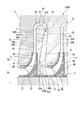
- FIG. 5 is an enlarged cross-sectional view of a main part of a centrifugal compressor according to the second embodiment of the present invention.
- the centrifugal compressor 100 ⁇ / b> B in this embodiment includes a return vane 50 ⁇ / b> B in the guide channel 25.
- the rear edge 52B located inside the radial direction Dd has a second end 52b on the second side in the axis O direction rather than the first end 52a on the first side in the axis O direction. And is formed so as to be located inside the radial direction Dd.
- the trailing edge 52B of the return vane 50B has a second end from the first end 52a and a normal line V extending perpendicularly to the upstream side wall surface on the first side in the axis O direction in the guide channel 25.
- the part 52b is located inside the radial direction Dd.
- the rear edge 52B of the return vane 50B is such that the intermediate portion 52c between the first end portion 52a and the second end portion 52b is directed toward the downstream side in the flow direction of the working fluid G, that is, toward the inner side in the radial direction Dd. And curved so as to be convex.
- the return vane 50B provided in the guide flow path 25 has the rear edge 52B positioned inside the radial direction Dd and the first in the axis O direction.
- the second end portion 52b on the second side in the direction of the axis O is formed so as to be located inside the radial direction Dd with respect to the first end portion 52a on the side.
- the swirl component remaining in the working fluid G that has passed through the return vane 50B can be more uniformly suppressed in the direction of the axis O. As a result, the efficiency of the centrifugal compressor 100B can be improved.
- the trailing edge 52B of the return vane 50B is curved and formed so as to protrude downstream along the flow direction of the working fluid G between the first end portion 52a and the second end portion 52b. .
- the suppression effect of the turning component of the working fluid G provided by the return vane 50B can be increased / decreased in the intermediate part 52c between the first end part 52a and the second end part 52b.
- the effect of suppressing the swirling component of the working fluid G can be optimized.
- FIG. 6 is an enlarged cross-sectional view of a main part in a modification of the centrifugal compressor according to the second embodiment of the present invention.
- the return vane 50C provided in the guide flow path 25 of the centrifugal compressor 100C has a trailing edge 52C at an intermediate portion between the first end 52a and the second end 52b.
- 52d may be formed to be concave on the upstream side (outside of the radial direction Dd) along the flow direction of the working fluid G.
- the number of compression stages (the number of impellers 4 and flow paths 2) of the centrifugal compressors 100, 100B, and 100C is not limited depending on the above-described embodiment, and may be appropriately set according to the design and specifications.
- the guide flow path 25 guides the working fluid G to at least one of the impellers 4 provided in a plurality of stages.
- the return vanes 50, 50B, and 50C shown in the first embodiment and the second embodiment may be provided.
- the present invention is applicable to a centrifugal rotating machine.
Abstract
流路は、上流側のインペラ(4)から径方向外側に向かって排出される作動流体を径方向内側に反転させて案内するリターンベンド部(24)と、リターンベンド部(24)の下流側に接続されて、作動流体を径方向内側に導いて下流側のインペラ(4)に案内する案内流路(25)と、を有する。案内流路(25)に設けられたリターンベーン(50)は、後縁(52)が、軸線方向の第一の側の第一端部(52a)よりも、軸線方向の第二の側の第二端部(52b)が、径方向(Dd)の内側に位置するよう形成されている。
Description
本発明は、遠心回転機械に関する。
本願は、2017年2月22日に、日本に出願された特願2017-031196号に基づき優先権を主張し、その内容をここに援用する。
本願は、2017年2月22日に、日本に出願された特願2017-031196号に基づき優先権を主張し、その内容をここに援用する。
遠心圧縮機等の回転機械は、軸線回りに回転するインペラと、インペラの外周側を覆うことでインペラとの間に作動流体の流路を形成するケーシングと、を主に備えている。
軸線方向に複数段のインペラを備える多段の回転機械は、各段の流路が、ディフューザ流路と、リターンベンド部と、案内流路と、を備える。ディフューザ流路は、インペラの径方向外側に設けられてインペラから軸線の径方向外側に延び、インペラの出口から吐出された作動流体を径方向外側に導く。リターンベンド部は、ディフューザ流路の径方向外側に連続して設けられ、作動流体の流れの方向を、径方向外側から内側に向かって反転させる。案内流路は、リターンベンド部の下流側に設けられて、後段側のインペラの入口に作動流体を導く。
軸線方向に複数段のインペラを備える多段の回転機械は、各段の流路が、ディフューザ流路と、リターンベンド部と、案内流路と、を備える。ディフューザ流路は、インペラの径方向外側に設けられてインペラから軸線の径方向外側に延び、インペラの出口から吐出された作動流体を径方向外側に導く。リターンベンド部は、ディフューザ流路の径方向外側に連続して設けられ、作動流体の流れの方向を、径方向外側から内側に向かって反転させる。案内流路は、リターンベンド部の下流側に設けられて、後段側のインペラの入口に作動流体を導く。
ところで、インペラの出口から吐出される作動流体は、インペラの軸線周りの回転による旋回方向の成分を有している。作動流体が、旋回成分が残ったまま、ディフューザ流路、リターンベンド部、案内流路を経て後段側のインペラに到達すると、後段側のインペラにおける作動流体に対する圧縮処理に悪影響を及ぼし、回転機械の効率低下に繋がる場合がある。
特許文献1、2には、上記案内流路に、整流を目的としたリターンベーン(案内羽根、羽根)を備えた構成が開示されている。案内流路にリターンベーンを設けることで、インペラの出口から吐出され、ディフューザ流路、リターンベンドを経た作動流体の旋回方向の成分を取り除き、回転機械の効率低下を抑えている。
しかしながら、特許文献1、2に記載された構成においては、リターンベーンを設けても、リターンベーンの出口において、作動流体の旋回方向の成分を完全に取り除くことは困難である。このため、リターンベーンの出口において、案内流路には、作動流体の旋回方向の速度成分に分布が生じてしまう。例えば、案内流路において、インペラの軸線方向の上流側と下流側とで、リターンベーンを経た作動流体に残る旋回方向の速度成分の大きさに、差が生じる場合がある。
そこで、本発明は、上記事情に鑑みてなされたものであり、リターンベーンを経た作動流体に残る旋回成分を抑え、回転機械の効率を向上させることができる遠心回転機械を提供することを目的とする。
本発明は、上記課題を解決するため、以下の手段を採用する。
本発明の第一の態様の遠心回転機械では、軸線方向に沿って複数段に設けられ、前記軸線方向の第一の側から吸い込んだ作動流体を前記軸線の径方向外側に吐出するインペラと、前記インペラを囲うよう設けられて、前記軸線方向の第一の側に位置する上流側の前記インペラから吐出される前記作動流体を、前記軸線方向の第二の側に位置する下流側の前記インペラに導く流路を形成するケーシングと、を備える。前記流路は、上流側の前記インペラから径方向外側に向かって排出される前記作動流体を径方向内側に反転させて案内するリターンベンド部と、前記リターンベンド部の下流側に接続されて、前記作動流体を径方向内側に導いて下流側の前記インペラに案内する案内流路と、を有する。遠心回転機械は、複数段に設けられた前記インペラのうちの少なくとも一つの前記インペラに前記作動流体を案内する前記案内流路に設けられ、前記軸線回りの周方向に間隔をあけて複数設けられたリターンベーンをさらに備える。前記リターンベーンは、径方向内側に位置する後縁が、前記軸線方向の前記第一の側の第一端部よりも、前記軸線方向の前記第二の側の第二端部が、径方向内側に位置するよう形成されている。
本発明の第一の態様の遠心回転機械では、軸線方向に沿って複数段に設けられ、前記軸線方向の第一の側から吸い込んだ作動流体を前記軸線の径方向外側に吐出するインペラと、前記インペラを囲うよう設けられて、前記軸線方向の第一の側に位置する上流側の前記インペラから吐出される前記作動流体を、前記軸線方向の第二の側に位置する下流側の前記インペラに導く流路を形成するケーシングと、を備える。前記流路は、上流側の前記インペラから径方向外側に向かって排出される前記作動流体を径方向内側に反転させて案内するリターンベンド部と、前記リターンベンド部の下流側に接続されて、前記作動流体を径方向内側に導いて下流側の前記インペラに案内する案内流路と、を有する。遠心回転機械は、複数段に設けられた前記インペラのうちの少なくとも一つの前記インペラに前記作動流体を案内する前記案内流路に設けられ、前記軸線回りの周方向に間隔をあけて複数設けられたリターンベーンをさらに備える。前記リターンベーンは、径方向内側に位置する後縁が、前記軸線方向の前記第一の側の第一端部よりも、前記軸線方向の前記第二の側の第二端部が、径方向内側に位置するよう形成されている。
このような構成によれば、リターンベーンにおいて径方向内側に位置する後縁の第二端部が第一端部よりも径方向内側に位置している。これにより、案内流路内でリターンベーンに沿って流れる作動流体に対し、リターンベーンによって付与される作動流体の旋回成分の抑制効果が、軸線方向の第一の側よりも軸線方向の第二の側で高くなる。したがって、リターンベーンを経た作動流体に残る旋回成分を抑えることが可能となる。
本発明の第二の態様の遠心回転機械では、上記第一の態様において、前記リターンベーンは、前記作動流体の流れ方向に沿った長さが、前記軸線方向の前記第一の側よりも前記軸線方向の前記第二の側が長くなるよう形成されていてもよい。
このように、作動流体の流れ方向に沿ったリターンベーンの長さを、軸線方向の第一の側(上流側)よりも第二の側(下流側)で大きくすることで、案内流路内で作動流体がリターンベーンに沿って流れる長さを大きくすることができる。これによって、作動流体の旋回成分の抑制効果を、軸線方向の第二の側で高めることができる。
本発明の第三の態様の遠心回転機械では、上記第一又は第二の態様において、前記リターンベーンの前記後縁は、前記第一端部から前記第二端部に向かうにしたがって、漸次前記径方向内側に延びていてもよい。
これにより、軸線方向の第一の側から第二の側に向かって、作動流体の旋回成分の抑制効果を徐々に高めることができる。
本発明の第四の態様の遠心回転機械では、上記第一又は第二の態様において、前記リターンベーンの前記後縁は、前記第一端部と前記第二端部との間で、径方向内側に向かって凸又は径方向外側に向かって凹となるよう湾曲して形成されているようにしてもよい。
このように構成することで、軸線方向の第一の側の第一端部と、軸線方向の第二の側の第二端部との間で、リターンベーンによって付与する作動流体の旋回成分の抑制効果を増減させることができる。これによって、作動流体の旋回成分の抑制効果を最適化することが可能となる。
本発明の第五の態様の遠心回転機械によれば、上記第一から第四の態様において、前記リターンベーンの前記後縁は、前記第一端部から前記案内流路において前記軸線方向の前記第一の側の上流側壁面に直交して延びる法線よりも、前記第二端部が径方向内側に位置するようにしてもよい。
これにより、リターンベーンの後縁において、第一端部よりも第二端部が径方向内側に位置する。
本発明の第六の態様の遠心回転機械によれば、上記第一から第五の態様において、前記リターンベーンは、径方向外側に位置する前縁が、前記軸線に沿って直線状に形成されているようにしてもよい。
このように、前縁を直線状に形成することで、前縁を容易に加工することが可能となる。
本発明の第七の態様の遠心回転機械によれば、上記第一から第六の態様において、前記リターンベーンは、径方向外側に位置する前縁よりも、前記後縁における前記軸線方向の長さが大きいようにしてもよい。
本発明に係る遠心回転機械によれば、リターンベーンを経た作動流体に残る旋回成分を抑え、回転機械の効率を向上させることができる。
以下、本発明の一実施形態に係る遠心圧縮機(遠心回転機械)を図面に基づき説明する。
(第一実施形態)
図1は、本発明の各実施形態に係る遠心圧縮機の構成を示す模式図である。図2は、本発明の第一実施形態に係る遠心圧縮機の案内流路の構成を示す図であり、案内流路を軸線方向に交差する方向から見た図である。図3は、遠心圧縮機の要部拡大断面図である。図4は、上記案内流路の軸線方向における案内流路出口での旋回成分の分布を示す図である。
図1に示すように、遠心圧縮機100は、ロータ1と、ケーシング3と、ロータ1に設けられた複数段のインペラ4と、を備えている。
(第一実施形態)
図1は、本発明の各実施形態に係る遠心圧縮機の構成を示す模式図である。図2は、本発明の第一実施形態に係る遠心圧縮機の案内流路の構成を示す図であり、案内流路を軸線方向に交差する方向から見た図である。図3は、遠心圧縮機の要部拡大断面図である。図4は、上記案内流路の軸線方向における案内流路出口での旋回成分の分布を示す図である。
図1に示すように、遠心圧縮機100は、ロータ1と、ケーシング3と、ロータ1に設けられた複数段のインペラ4と、を備えている。
ロータ1は、ケーシング3の内部を軸線Oに沿って貫通するように延びている。軸線O方向におけるケーシング3の両端部には、それぞれジャーナル軸受5及びスラスト軸受6が設けられている。ロータ1は、これらジャーナル軸受5とスラスト軸受6とによって軸線O回りに回転可能に支持されている。
ケーシング3は、おおむね軸線Oに沿って延びる円筒状をなしている。ケーシング3の内側には、縮径と拡径を繰り返す内部空間が形成されている。ケーシング3は、内部空間に複数のインペラ4を収容することで、ロータ1及び複数段のインペラ4の周囲を覆うよう設けられ、ロータ1との間に流路2を形成する。
ケーシング3の軸線O方向の第一の側には、外部から作動流体Gとしての空気を取り入れて流路2に送り込むための吸気口7が設けられている。さらに、ケーシング3の軸線O方向の第二の側には、ケーシング3の内部で圧縮された作動流体Gが流路2から排気される排気口8が設けられている。なお、以降の説明では、吸気口7が位置する第一の側を上流側と呼び、排気口8が位置する第二の側を下流側と呼ぶ。
インペラ4は、ロータ1に、軸線O方向に間隔を空けて複数段、例えば図1の例では6段が設けられている。各インペラ4は、軸線O方向の第一の側から吸い込んだ作動流体Gを軸線Oの径方向Ddの外側に吐出する。
図2に示すように、それぞれのインペラ4は、ディスク41と、羽根42と、シュラウド43と、を有している。
図2に示すように、それぞれのインペラ4は、ディスク41と、羽根42と、シュラウド43と、を有している。
ディスク41は、軸線O方向から見て略円形をなしている。ディスク41は、軸線Oと交差する方向から見て、前記軸線O方向の第一の側(図2における左方)から第二の側(図2における右方)に向かうに従って、径方向の寸法が次第に拡大するように形成されることで、おおむね円錐状をなしている。
羽根42は、上記のディスク41の軸線O方向における両面のうち、上流側を向く円錐上の面に設けられている。羽根42は、軸線Oを中心として径方向Ddの外側に向かって放射状に複数配列されている。より詳しくは、これら羽根42は、ディスク41の上流側の面から上流側に向かって立設された薄板によって形成されている。さらに、詳しくは図示しないが、これら複数の羽根42は、軸線O方向から見た場合、周方向の一方側から他方側に向かうように湾曲している。
シュラウド43は、羽根42の上流側の端縁に、これら複数の羽根42を上流側から覆うように設けられている。言い換えると、上記複数の羽根42は、このシュラウド43とディスク41とによっておおむね軸線O方向から挟持されている。これにより、シュラウド43、ディスク41、及び互いに隣り合う一対の羽根42同士の間には空間が形成される。この空間は、後述する流路2の一部(圧縮流路22)をなしている。
流路2は、上記のように構成されたインペラ4と、ケーシング3の内部空間をそれぞれ連通する空間である。本実施形態では、1つのインペラ4ごと(1つの圧縮段ごと)に1つの流路2が形成されているものとして説明を行う。流路2は、軸線O方向の第一の側に位置する上流側のインペラ4から吐出される作動流体Gを、軸線O方向の第二の側に位置する下流側のインペラ4に導く。即ち、遠心圧縮機100では、最後段のインペラ4を除く5つのインペラ4に対応して、上流側から下流側に向かって連続する5つの流路2が形成されている。
それぞれの流路2は、吸込流路21と、圧縮流路22と、ディフューザ流路23と、リターンベンド部24と、案内流路25と、を有している。
1段目のインペラ4では、吸込流路21は上記の吸気口7と実質的に直接接続されている。この吸込流路21によって、外部の空気が流路2に作動流体Gとして取り込まれる。
より具体的には、この吸込流路21は、上流側から下流側に向かうにしたがって、軸線O方向から径方向Ddの外側に向かって次第に湾曲している。
より具体的には、この吸込流路21は、上流側から下流側に向かうにしたがって、軸線O方向から径方向Ddの外側に向かって次第に湾曲している。
2段目以降のインペラ4における吸込流路21は、前段(1段目)の流路2における案内流路25(後述)の下流端と連通している。即ち、案内流路25を通過した作動流体Gは、上記と同様に、軸線Oに沿って下流側を向くように、その流れ方向が変更される。
圧縮流路22は、ディスク41の上流側の面、シュラウド43の下流側の面、及び周方向に隣り合う一対の羽根42によって囲まれた流路である。より詳しくは、この圧縮流路22は、径方向Ddの内側から外側に向かうに従って、その断面積が次第に減少している。これにより、インペラ4が回転している状態で圧縮流路22中を流通する作動流体Gは、徐々に圧縮されて高圧流体となる。
ディフューザ流路23は、ケーシング3の内部空間を形成する内周壁の一部であるディフューザ前壁23Aと、隔壁部材31のディフューザ後壁23Bとによって囲まれることで、軸線Oの径方向Ddの内側から外側に向かって延びる流路である。このディフューザ流路23における径方向Ddの内側の端部は、上記圧縮流路22の径方向Ddの外側の端部に連通している。
なお、上記の隔壁部材31は、ケーシング3の内周側に一体に設けられることで、軸線O方向に隣接する複数のインペラ4同士の間を隔てる部材である。さらに、この隔壁部材31から見て、ディフューザ流路23及びインペラ4を挟んで上流側には、同じくケーシング3と一体に設けられた延伸部32が設けられている。延伸部32は、ケーシング3の内周面(不図示)から径方向Ddの内側に向かって延びる壁部である。
リターンベンド部24は、ケーシング3の反転壁33と、隔壁部材31の外周壁31Aとで囲まれた、湾曲する流路である。リターンベンド部24の一端側(上流側)は、上記ディフューザ流路23に連通し、他端側(下流側)は、案内流路25に連通している。
リターンベンド部24は、上流側のインペラ4から径方向Ddの外側に向かって排出され、ディフューザ流路23を経た作動流体Gの流れ方向を反転させて、径方向Ddの内側に案内する。
リターンベンド部24は、上流側のインペラ4から径方向Ddの外側に向かって排出され、ディフューザ流路23を経た作動流体Gの流れ方向を反転させて、径方向Ddの内側に案内する。
案内流路25は、ケーシング3における上記の隔壁部材31において下流側を向く側壁31Bと、延伸部32において上流側を向く側壁32Aとで囲まれた流路である。ここで、側壁31Bは、案内流路25において軸線O方向の第一の側の上流側壁面を形成する。
案内流路25の径方向Ddの外側の端部は、上記のリターンベンド部24の下流側に接続されている。さらに、案内流路25の径方向Ddの内側の端部は、上述のように後段の流路2における吸込流路21に連通している。案内流路25は、リターンベンド部24を経た作動流体Gを径方向Ddの内側に導いて下流側のインペラ4に案内する。
案内流路25の径方向Ddの外側の端部は、上記のリターンベンド部24の下流側に接続されている。さらに、案内流路25の径方向Ddの内側の端部は、上述のように後段の流路2における吸込流路21に連通している。案内流路25は、リターンベンド部24を経た作動流体Gを径方向Ddの内側に導いて下流側のインペラ4に案内する。
遠心圧縮機100は、案内流路25に、リターンベーン50を備えている。図3に示すように、リターンベーン50は、軸線Oの周囲で周方向に間隔を空けて、複数が設けられている。これら複数のリターンベーン50は、案内流路25中で、軸線Oを中心として放射状に配列されている。具体的には、それぞれのリターンベーン50は、隔壁部材31の側壁31Bから、延伸部32の側壁32Aに向かって延びる板材によって形成されている。各リターンベーン50は、径方向Ddの外側に位置する前縁51、及び径方向Ddの内側に位置する後縁52に対し、径方向の中間部53が、インペラ4の回転方向の一方側に向かって膨出して湾曲した形状をなしている。また、各リターンベーン50は、後縁52が、径方向Ddにおいて、軸線O(ロータ1の中心)に向かって延びるよう形成されている。
各リターンベーン50は、径方向Ddの外側に位置する前縁51が、案内流路25内を流れる作動流体の流れ方向Fに対して直交して、即ち軸線Oに沿って(本実施形態では、軸線Oに平行に)直線状に形成されている。
リターンベーン50は、径方向Ddの内側に位置する後縁52が、軸線O方向の第一の側の第一端部52aよりも、軸線O方向の第二の側の第二端部52bが、径方向Ddの内側に位置するよう形成されている。具体的には、リターンベーン50の後縁52は、第一端部52aから側壁31Bに直交して延びる法線Vよりも、第二端部52bが径方向Ddの内側に位置する。さらに、リターンベーン50の後縁52は、第一端部52aから第二端部52bに向かうにしたがって、漸次径方向Ddの内側に直線状に延びている。
これにより、リターンベーン50は、作動流体Gの流れ方向に沿った前縁51から後縁52までの長さが、軸線O方向の第一の側よりも軸線O方向の第二の側で長くなるよう形成されている。
これにより、リターンベーン50は、作動流体Gの流れ方向に沿った前縁51から後縁52までの長さが、軸線O方向の第一の側よりも軸線O方向の第二の側で長くなるよう形成されている。
また、上記リターンベーン50は、径方向外側に位置する前縁51よりも、後縁52における軸線方向Oの長さが大きくなるよう形成されている。
続いて、本実施形態に係る遠心圧縮機100の動作について説明する。
通常の運転状態にある遠心圧縮機100では、作動流体Gは以下のような挙動を示す。
まず、吸気口7から流路2内に取り込まれた作動流体Gは、1段目の吸込流路21を経て、インペラ4中の圧縮流路22に流入する。インペラ4はロータ1の回転に伴って軸線O回りに回転していることから、圧縮流路22中の作動流体Gには、軸線Oから径方向Ddの外側に向かう遠心力が付加される。加えて、上記の通り、圧縮流路22の断面積は径方向Ddの外側から内側にかけて次第に減少していることから、作動流体Gは徐々に圧縮される。これにより、高圧の作動流体Gが、圧縮流路22から後続のディフューザ流路23に送り出される。
通常の運転状態にある遠心圧縮機100では、作動流体Gは以下のような挙動を示す。
まず、吸気口7から流路2内に取り込まれた作動流体Gは、1段目の吸込流路21を経て、インペラ4中の圧縮流路22に流入する。インペラ4はロータ1の回転に伴って軸線O回りに回転していることから、圧縮流路22中の作動流体Gには、軸線Oから径方向Ddの外側に向かう遠心力が付加される。加えて、上記の通り、圧縮流路22の断面積は径方向Ddの外側から内側にかけて次第に減少していることから、作動流体Gは徐々に圧縮される。これにより、高圧の作動流体Gが、圧縮流路22から後続のディフューザ流路23に送り出される。
圧縮流路22から流れ出た高圧の作動流体Gは、その後、ディフューザ流路23、リターンベンド部24、案内流路25を順に通過する。以後、2段目以降のインペラ4、及び流路2においても同様の圧縮が加えられる。最終的には、作動流体Gは、所望の圧力状態となって排気口8から不図示の外部機器に供給される。
ここで、案内流路25を通過する作動流体Gは、案内流路25に設けられたリターンベーン50によって、その軸線O回りの旋回成分が低減される。リターンベーン50は、作動流体Gの流れ方向に沿った長さが、軸線O方向の第一の側よりも軸線O方向の第二の側が長い。これにより、案内流路25内でリターンベーン50に沿って流れる作動流体Gに対して、リターンベーン50によって付与される作動流体Gの旋回成分の抑制効果は、軸線O方向の第一側の第一端部52a側よりも第二の側の第二端部52b側で高まる。
図4は、リターンベーン50の後縁52を、第一端部52aに対して第二端部52bを径方向Ddの内側に位置させた場合における旋回成分の強さの分布Pを示す図である。この図4には、比較のため、後縁52の第一端部52aと第二端部52bとを、径方向で同一位置、つまり後縁52を軸線O方向に沿った直線状に形成した場合の旋回成分の強さの分布Qを示している。
この図4に示すように、リターンベーン50の後縁52を、第一端部52aに対して第二端部52bを径方向Ddの内側に位置させることで、リターンベーン50を経た作動流体Gに残る旋回成分を、軸線O方向において、より均一に抑えることが可能となる。
この図4に示すように、リターンベーン50の後縁52を、第一端部52aに対して第二端部52bを径方向Ddの内側に位置させることで、リターンベーン50を経た作動流体Gに残る旋回成分を、軸線O方向において、より均一に抑えることが可能となる。
以上、説明したように、本実施形態に係る遠心圧縮機100では、案内流路25に設けられたリターンベーン50は、径方向Ddの内側に位置する後縁52が、軸線O方向の第一の側の第一端部52aよりも、軸線O方向の第二の側の第二端部52bが、径方向Ddの内側に位置するよう形成されている。このような構成によれば、案内流路25内でリターンベーン50に沿って流れる作動流体Gに対し、リターンベーン50によって付与される作動流体Gの旋回成分の抑制効果が、軸線O方向の第二の側で、より高まるので、リターンベーン50を経た作動流体Gに残る旋回成分を、軸線O方向において、より均一に抑えることが可能となる。その結果、遠心圧縮機100の効率を向上させることが可能となる。
また、作動流体Gの流れ方向に沿ったリターンベーン50の長さを、軸線O方向の第一の側よりも第二の側で大きくすることで、案内流路25内で作動流体Gがリターンベーン50に沿って流れる長さを大きくすることができる。これによって、作動流体Gの旋回成分の抑制効果を、軸線O方向の第二の側で高めることができる。
また、リターンベーン50の後縁52は、第一端部52aから第二端部52bに向かうにしたがって、漸次径方向Ddの内側に延びている。これにより、軸線O方向の第一の側から第二の側に向かって、作動流体Gの旋回成分の抑制効果を徐々に高めることができる。
また、リターンベーン50は、前縁51が、作動流体Gの流れ方向に対して直交して直線状に形成されている。このように、前縁51を直線状に形成することで、前縁51を容易に加工することが可能となる。
(第二実施形態)
次に、本発明にかかる遠心回転機械の第二実施形態について説明する。以下に説明する第二実施形態においては、第一実施形態とリターンベーン50Bの後縁52Bの形状のみが異なるので、第一実施形態と同一部分に同一符号を付して説明するとともに、重複説明を省略する。
次に、本発明にかかる遠心回転機械の第二実施形態について説明する。以下に説明する第二実施形態においては、第一実施形態とリターンベーン50Bの後縁52Bの形状のみが異なるので、第一実施形態と同一部分に同一符号を付して説明するとともに、重複説明を省略する。
図5は、本発明の第二実施形態に係る遠心圧縮機の要部拡大断面図である。
図5に示すように、この実施形態における遠心圧縮機100Bは、案内流路25に、リターンベーン50Bを備えている。
図5に示すように、この実施形態における遠心圧縮機100Bは、案内流路25に、リターンベーン50Bを備えている。
リターンベーン50Bは、径方向Ddの内側に位置する後縁52Bが、軸線O方向の第一の側の第一端部52aよりも、軸線O方向の第二の側の第二端部52bが、径方向Ddの内側に位置するよう形成されている。具体的には、リターンベーン50Bの後縁52Bは、第一端部52aから案内流路25において軸線O方向の第一の側の上流側壁面に直交して延びる法線Vよりも第二端部52bが径方向Ddの内側に位置する。
リターンベーン50Bの後縁52Bは、第一端部52aと第二端部52bとの間の中間部52cが、作動流体Gの流れ方向の下流側に向かって、即ち径方向Ddの内側に向かって凸となるよう湾曲して形成されている。
以上、説明したように、本実施形態に係る遠心圧縮機100Bでは、案内流路25に設けられたリターンベーン50Bは、径方向Ddの内側に位置する後縁52Bが、軸線O方向の第一の側の第一端部52aよりも、軸線O方向の第二の側の第二端部52bが、径方向Ddの内側に位置するよう形成されている。このような構成によれば、案内流路25内でリターンベーン50Bに沿って流れる作動流体Gに対し、リターンベーン50Bによって付与される作動流体Gの旋回成分の抑制効果が、軸線O方向の第二の側で、より高まるので、リターンベーン50Bを経た作動流体Gに残る旋回成分を、軸線O方向において、より均一に抑えることが可能となる。その結果、遠心圧縮機100Bの効率を向上させることが可能となる。
また、リターンベーン50Bの後縁52Bは、第一端部52aと第二端部52bとの間で、作動流体Gの流れ方向に沿って下流側に凸となるよう湾曲して形成されている。このように構成することで、第一端部52aと第二端部52bとの間の中間部52cで、リターンベーン50Bによって付与する作動流体Gの旋回成分の抑制効果を増減させることができる。これによって、軸線O方向における作動流体の旋回成分の残存度合いに応じて後縁52の形状を形成することで、作動流体Gの旋回成分の抑制効果を最適化することが可能となる。
(第二実施形態の変形例)
なお、上記第二実施形態において、リターンベーン50Bの後縁52Bを、第一端部52aと第二端部52bとの間の中間部52cが、作動流体Gの流れ方向に沿って下流側(径方向Ddの内側)に凸となるように形成したが、これに限らない。
図6は、本発明の第二実施形態に係る遠心圧縮機の変形例における要部拡大断面図である。
例えば、この図6に示すように、遠心圧縮機100Cの案内流路25に設けられたリターンベーン50Cは、後縁52Cを、第一端部52aと第二端部52bとの間の中間部52dが、作動流体Gの流れ方向に沿って上流側(径方向Ddの外側)に凹となるように形成してもよい。
なお、上記第二実施形態において、リターンベーン50Bの後縁52Bを、第一端部52aと第二端部52bとの間の中間部52cが、作動流体Gの流れ方向に沿って下流側(径方向Ddの内側)に凸となるように形成したが、これに限らない。
図6は、本発明の第二実施形態に係る遠心圧縮機の変形例における要部拡大断面図である。
例えば、この図6に示すように、遠心圧縮機100Cの案内流路25に設けられたリターンベーン50Cは、後縁52Cを、第一端部52aと第二端部52bとの間の中間部52dが、作動流体Gの流れ方向に沿って上流側(径方向Ddの外側)に凹となるように形成してもよい。
以上、本発明の各実施形態について図面を参照して説明した。しかしながら、上記の各実施形態はいずれも一例であって、これらの構成に種々の変更を施すことが可能である。
例えば、遠心圧縮機100,100B、100Cの圧縮段数(インペラ4、流路2の数)は、上記実施形態によっては限定されず、設計や仕様に応じて適宜に設定されてよい。
例えば、遠心圧縮機100,100B、100Cの圧縮段数(インペラ4、流路2の数)は、上記実施形態によっては限定されず、設計や仕様に応じて適宜に設定されてよい。
また、上記の第一実施形態、第二実施形態で示したリターンベーン50、50B、50Cは、遠心圧縮機100、100B、100Cの全ての段に備えることは必須ではない。
複数段に設けられたインペラ4のうちの少なくとも一つのインペラ4に作動流体Gを案内する案内流路25に。上記の第一実施形態、第二実施形態で示したリターンベーン50、50B、50Cが設けられていればよい。
複数段に設けられたインペラ4のうちの少なくとも一つのインペラ4に作動流体Gを案内する案内流路25に。上記の第一実施形態、第二実施形態で示したリターンベーン50、50B、50Cが設けられていればよい。
本発明は、遠心回転機械に適用可能である。
1 ロータ
2 流路
3 ケーシング
4 インペラ
5 ジャーナル軸受
6 スラスト軸受
7 吸気口
8 排気口
21 吸込流路
22 圧縮流路
23 ディフューザ流路
23A ディフューザ前壁
23B ディフューザ後壁
24 リターンベンド部
25 案内流路
31 隔壁部材
31A 外周壁
31B 側壁
32 延伸部
32A 側壁
33 反転壁
41 ディスク
42 羽根
43 シュラウド
50、50B、50C リターンベーン
51 前縁
52、52B、52C 後縁
52a 第一端部
52b 第二端部
52c、52d 中間部
53 中間部
100、100B、100C 遠心圧縮機(遠心回転機械)
Dd 径方向
F 流れ方向
G 作動流体
O 軸線
Claims (7)
- 軸線方向に沿って複数段に設けられ、前記軸線方向の第一の側から吸い込んだ作動流体を前記軸線の径方向外側に吐出するインペラと、
前記インペラを囲うよう設けられて、前記軸線方向の第一の側に位置する上流側の前記インペラから吐出される前記作動流体を、前記軸線方向の第二の側に位置する下流側の前記インペラに導く流路を形成するケーシングと、を備え、
前記流路は、上流側の前記インペラから径方向外側に向かって排出される前記作動流体を径方向内側に反転させて案内するリターンベンド部と、
前記リターンベンド部の下流側に接続されて、前記作動流体を径方向内側に導いて下流側の前記インペラに案内する案内流路と、を有し、
複数段に設けられた前記インペラのうちの少なくとも一つの前記インペラに前記作動流体を案内する前記案内流路に設けられ、前記軸線回りの周方向に間隔をあけて複数設けられたリターンベーンをさらに備え、
前記リターンベーンは、径方向内側に位置する後縁が、前記軸線方向の前記第一の側の第一端部よりも、前記軸線方向の前記第二の側の第二端部が、径方向内側に位置するよう形成されている遠心回転機械。 - 前記リターンベーンは、前記作動流体の流れ方向に沿った長さが、前記軸線方向の前記第一の側よりも前記軸線方向の前記第二の側が長くなるよう形成されている請求項1に記載の遠心回転機械。
- 前記リターンベーンの前記後縁は、前記第一端部から前記第二端部に向かうにしたがって、漸次前記径方向内側に延びている請求項1又は2に記載の遠心回転機械。
- 前記リターンベーンの前記後縁は、前記第一端部と前記第二端部との間で、径方向内側に向かって凸又は径方向外側に向かって凹となるよう湾曲して形成されている請求項1又は2に記載の遠心回転機械。
- 前記リターンベーンの前記後縁は、前記第一端部から前記案内流路において前記軸線方向の前記第一の側の上流側壁面に直交して延びる法線よりも前記第二端部が径方向内側に位置する請求項1から4の何れか一項に記載の遠心回転機械。
- 前記リターンベーンは、径方向外側に位置する前縁が、前記軸線に沿って直線状に形成されている請求項1から5の何れか一項に記載の遠心回転機械。
- 前記リターンベーンは、径方向外側に位置する前縁よりも、前記後縁における前記軸線方向の長さが大きい請求項1から6の何れか一項に記載の遠心回転機械。
Priority Applications (2)
| Application Number | Priority Date | Filing Date | Title |
|---|---|---|---|
| EP18757813.3A EP3567260B1 (en) | 2017-02-22 | 2018-02-20 | Centrifugal rotary machine |
| US16/484,496 US10975883B2 (en) | 2017-02-22 | 2018-02-20 | Centrifugal rotary machine |
Applications Claiming Priority (2)
| Application Number | Priority Date | Filing Date | Title |
|---|---|---|---|
| JP2017031196A JP6763803B2 (ja) | 2017-02-22 | 2017-02-22 | 遠心回転機械 |
| JP2017-031196 | 2017-02-22 |
Publications (1)
| Publication Number | Publication Date |
|---|---|
| WO2018155458A1 true WO2018155458A1 (ja) | 2018-08-30 |
Family
ID=63253293
Family Applications (1)
| Application Number | Title | Priority Date | Filing Date |
|---|---|---|---|
| PCT/JP2018/006083 WO2018155458A1 (ja) | 2017-02-22 | 2018-02-20 | 遠心回転機械 |
Country Status (4)
| Country | Link |
|---|---|
| US (1) | US10975883B2 (ja) |
| EP (1) | EP3567260B1 (ja) |
| JP (1) | JP6763803B2 (ja) |
| WO (1) | WO2018155458A1 (ja) |
Cited By (1)
| Publication number | Priority date | Publication date | Assignee | Title |
|---|---|---|---|---|
| WO2023238541A1 (ja) * | 2022-06-09 | 2023-12-14 | 株式会社日立インダストリアルプロダクツ | 多段遠心圧縮機 |
Families Citing this family (2)
| Publication number | Priority date | Publication date | Assignee | Title |
|---|---|---|---|---|
| JP6854687B2 (ja) * | 2017-04-05 | 2021-04-07 | 株式会社日立インダストリアルプロダクツ | 多段流体機械 |
| US10781705B2 (en) * | 2018-11-27 | 2020-09-22 | Pratt & Whitney Canada Corp. | Inter-compressor flow divider profiling |
Citations (6)
| Publication number | Priority date | Publication date | Assignee | Title |
|---|---|---|---|---|
| JPS62162398A (ja) | 1986-01-10 | 1987-07-18 | 松下電器産業株式会社 | 電子部品移載装置 |
| JPH06249200A (ja) * | 1993-02-23 | 1994-09-06 | Niigata Uoshinton Kk | 連続型ディフューザ |
| JP2002106487A (ja) | 2000-10-03 | 2002-04-10 | Hitachi Ltd | 多段遠心圧縮機 |
| US20120230812A1 (en) * | 2009-11-11 | 2012-09-13 | Werner Jonen | Intermediate floor for a radial turbine engine |
| JP2016031064A (ja) * | 2014-07-30 | 2016-03-07 | 株式会社日立製作所 | 多段ポンプ |
| JP2017031196A (ja) | 2000-10-31 | 2017-02-09 | アムジエン・インコーポレーテツド | 組換えエリスロポエチンと部分的に組合されたil−1インヒビターおよびtnfアンタゴニストの貧血治療用途 |
Family Cites Families (15)
| Publication number | Priority date | Publication date | Assignee | Title |
|---|---|---|---|---|
| US2419669A (en) * | 1942-05-08 | 1947-04-29 | Fed Reserve Bank | Diffuser for centrifugal compressors |
| GB884507A (en) * | 1960-06-02 | 1961-12-13 | Neu Sa | Improvements in or relating to centrifugal compressors |
| GB1107039A (en) * | 1964-12-15 | 1968-03-20 | G & J Weir Ltd | Multi-stage rotary fluid-flow machines |
| US4645419A (en) * | 1984-09-10 | 1987-02-24 | Ebara Corporation | Centrifugal compressor |
| JPS62162398U (ja) | 1986-04-03 | 1987-10-15 | ||
| US4725196A (en) * | 1986-09-19 | 1988-02-16 | Hitachi, Ltd. | Single-shaft multi-stage centrifugal compressor |
| JP3299638B2 (ja) * | 1994-09-20 | 2002-07-08 | 株式会社日立製作所 | ターボ流体機械 |
| DE102009019061A1 (de) * | 2009-04-27 | 2010-10-28 | Man Diesel & Turbo Se | Mehrstufiger Radialverdichter |
| FR2970508B1 (fr) * | 2011-01-13 | 2015-12-11 | Turbomeca | Assemblage de compression et turbomoteur equipe d'un tel assemblage |
| ITCO20120055A1 (it) * | 2012-11-06 | 2014-05-07 | Nuovo Pignone Srl | Pala di canale di ritorno per compressori centrifughi |
| ITFI20130208A1 (it) * | 2013-09-05 | 2015-03-06 | Nuovo Pignone Srl | "multistage centrifugal compressor" |
| JP3187468U (ja) | 2013-09-18 | 2013-11-28 | 株式会社日立製作所 | 多段遠心圧縮機 |
| EP2990662B1 (en) * | 2014-08-28 | 2017-06-14 | Nuovo Pignone S.r.l. | Centrifugal compressors with integrated intercooling |
| JP6667323B2 (ja) * | 2016-02-29 | 2020-03-18 | 三菱重工コンプレッサ株式会社 | 遠心回転機械 |
| US10760587B2 (en) * | 2017-06-06 | 2020-09-01 | Elliott Company | Extended sculpted twisted return channel vane arrangement |
-
2017
- 2017-02-22 JP JP2017031196A patent/JP6763803B2/ja active Active
-
2018
- 2018-02-20 US US16/484,496 patent/US10975883B2/en active Active
- 2018-02-20 EP EP18757813.3A patent/EP3567260B1/en active Active
- 2018-02-20 WO PCT/JP2018/006083 patent/WO2018155458A1/ja unknown
Patent Citations (6)
| Publication number | Priority date | Publication date | Assignee | Title |
|---|---|---|---|---|
| JPS62162398A (ja) | 1986-01-10 | 1987-07-18 | 松下電器産業株式会社 | 電子部品移載装置 |
| JPH06249200A (ja) * | 1993-02-23 | 1994-09-06 | Niigata Uoshinton Kk | 連続型ディフューザ |
| JP2002106487A (ja) | 2000-10-03 | 2002-04-10 | Hitachi Ltd | 多段遠心圧縮機 |
| JP2017031196A (ja) | 2000-10-31 | 2017-02-09 | アムジエン・インコーポレーテツド | 組換えエリスロポエチンと部分的に組合されたil−1インヒビターおよびtnfアンタゴニストの貧血治療用途 |
| US20120230812A1 (en) * | 2009-11-11 | 2012-09-13 | Werner Jonen | Intermediate floor for a radial turbine engine |
| JP2016031064A (ja) * | 2014-07-30 | 2016-03-07 | 株式会社日立製作所 | 多段ポンプ |
Non-Patent Citations (1)
| Title |
|---|
| See also references of EP3567260A4 |
Cited By (1)
| Publication number | Priority date | Publication date | Assignee | Title |
|---|---|---|---|---|
| WO2023238541A1 (ja) * | 2022-06-09 | 2023-12-14 | 株式会社日立インダストリアルプロダクツ | 多段遠心圧縮機 |
Also Published As
| Publication number | Publication date |
|---|---|
| EP3567260A4 (en) | 2020-01-22 |
| JP6763803B2 (ja) | 2020-09-30 |
| JP2018135815A (ja) | 2018-08-30 |
| EP3567260B1 (en) | 2020-12-30 |
| EP3567260A1 (en) | 2019-11-13 |
| US10975883B2 (en) | 2021-04-13 |
| US20200003226A1 (en) | 2020-01-02 |
Similar Documents
| Publication | Publication Date | Title |
|---|---|---|
| WO2011007467A1 (ja) | インペラおよび回転機械 | |
| JP5316365B2 (ja) | ターボ型流体機械 | |
| JP5709898B2 (ja) | 回転機械 | |
| WO2018181343A1 (ja) | 遠心圧縮機 | |
| JP2018135768A (ja) | 遠心圧縮機 | |
| WO2011007466A1 (ja) | インペラおよび回転機械 | |
| WO2018155458A1 (ja) | 遠心回転機械 | |
| JP5558183B2 (ja) | ターボ機械 | |
| WO2018155546A1 (ja) | 遠心圧縮機 | |
| WO2017150554A1 (ja) | 遠心回転機械 | |
| WO2018179112A1 (ja) | コンプレッサのスクロール形状及び過給機 | |
| US11047393B1 (en) | Multi-stage centrifugal compressor, casing, and return vane | |
| JP2021011828A (ja) | 多段遠心圧縮機 | |
| WO2017072844A1 (ja) | 回転機械 | |
| JP5428962B2 (ja) | 軸流圧縮機及びガスタービンエンジン | |
| JP2017057779A (ja) | ターボチャージャ | |
| JP6994976B2 (ja) | タービンの排気室及びタービン | |
| JP2022151994A (ja) | 回転機械 | |
| JP2023068953A (ja) | ベーンドディフューザおよび遠心圧縮機 | |
| JP2023023914A (ja) | 遠心圧縮機 | |
| JP2020133518A (ja) | ターボ圧縮機 | |
| JP2017172569A (ja) | 軸流圧縮機 | |
| JP2012057489A (ja) | 遠心圧縮機のディフューザおよびこれを備えた遠心圧縮機 |
Legal Events
| Date | Code | Title | Description |
|---|---|---|---|
| 121 | Ep: the epo has been informed by wipo that ep was designated in this application |
Ref document number: 18757813 Country of ref document: EP Kind code of ref document: A1 |
|
| ENP | Entry into the national phase |
Ref document number: 2018757813 Country of ref document: EP Effective date: 20190808 |
|
| NENP | Non-entry into the national phase |
Ref country code: DE |