WO2018143764A1 - 모터 - Google Patents
모터 Download PDFInfo
- Publication number
- WO2018143764A1 WO2018143764A1 PCT/KR2018/001554 KR2018001554W WO2018143764A1 WO 2018143764 A1 WO2018143764 A1 WO 2018143764A1 KR 2018001554 W KR2018001554 W KR 2018001554W WO 2018143764 A1 WO2018143764 A1 WO 2018143764A1
- Authority
- WO
- WIPO (PCT)
- Prior art keywords
- disposed
- bracket
- ground portion
- wire assembly
- stator
- Prior art date
Links
Images


Classifications
-
- H—ELECTRICITY
- H02—GENERATION; CONVERSION OR DISTRIBUTION OF ELECTRIC POWER
- H02K—DYNAMO-ELECTRIC MACHINES
- H02K11/00—Structural association of dynamo-electric machines with electric components or with devices for shielding, monitoring or protection
- H02K11/01—Structural association of dynamo-electric machines with electric components or with devices for shielding, monitoring or protection for shielding from electromagnetic fields, i.e. structural association with shields
- H02K11/014—Shields associated with stationary parts, e.g. stator cores
- H02K11/0141—Shields associated with casings, enclosures or brackets
-
- B—PERFORMING OPERATIONS; TRANSPORTING
- B62—LAND VEHICLES FOR TRAVELLING OTHERWISE THAN ON RAILS
- B62D—MOTOR VEHICLES; TRAILERS
- B62D5/00—Power-assisted or power-driven steering
- B62D5/04—Power-assisted or power-driven steering electrical, e.g. using an electric servo-motor connected to, or forming part of, the steering gear
-
- H—ELECTRICITY
- H02—GENERATION; CONVERSION OR DISTRIBUTION OF ELECTRIC POWER
- H02K—DYNAMO-ELECTRIC MACHINES
- H02K11/00—Structural association of dynamo-electric machines with electric components or with devices for shielding, monitoring or protection
- H02K11/40—Structural association with grounding devices
-
- H—ELECTRICITY
- H02—GENERATION; CONVERSION OR DISTRIBUTION OF ELECTRIC POWER
- H02K—DYNAMO-ELECTRIC MACHINES
- H02K5/00—Casings; Enclosures; Supports
- H02K5/04—Casings or enclosures characterised by the shape, form or construction thereof
- H02K5/22—Auxiliary parts of casings not covered by groups H02K5/06-H02K5/20, e.g. shaped to form connection boxes or terminal boxes
- H02K5/225—Terminal boxes or connection arrangements
-
- H—ELECTRICITY
- H02—GENERATION; CONVERSION OR DISTRIBUTION OF ELECTRIC POWER
- H02K—DYNAMO-ELECTRIC MACHINES
- H02K5/00—Casings; Enclosures; Supports
- H02K5/04—Casings or enclosures characterised by the shape, form or construction thereof
- H02K5/22—Auxiliary parts of casings not covered by groups H02K5/06-H02K5/20, e.g. shaped to form connection boxes or terminal boxes
Definitions
- Embodiments relate to a motor.
- the electric steering system is a device that enables the driver to drive safely by ensuring the vehicle's turning stability and providing a quick resilience.
- the electric steering device controls the driving of the steering shaft of the vehicle by driving a motor through an electronic control unit (ECU) according to the driving conditions detected by the vehicle speed sensor, the torque angle sensor, and the torque sensor.
- ECU electronice control unit
- the motor includes a housing.
- the housing includes a body and a bracket.
- the body houses the rotor and stator therein.
- the bracket covers the open top of the body.
- the bracket is provided with a receiving portion for receiving the wire assembly.
- the bracket is generally made of a metal material such as aluminum, but may be made of a plastic resin injection molded to include a bearing in the center portion. but. In the case of the bracket made of plastic resin, a fatal problem cannot be shielded due to the absence of electric current, which prevents EMI (Electro Magnetic Interference) from being shielded.
- EMI Electro Magnetic Interference
- the bracket may be additionally coupled to a separate component that can be energized to shield the Electro Magnetic Interference (EMI). Therefore, there is a problem in that the structure of the bracket is complicated. In addition, there is a problem that a ground fault may occur between the wire assembly and the bracket.
- EMI Electro Magnetic Interference
- the bracket is made of a metal material such as aluminum, but may be made of a plastic resin injection-molded to include a bearing in the center portion. but.
- EMI Electro Magnetic Interference
- an embodiment is to solve the above problems, an object of the present invention to provide a motor that can prevent the provision of a motor that can shield the EMI in the bracket made of plastic resin.
- an embodiment is to provide a motor capable of shielding EMI in a bracket made of a plastic resin.
- An embodiment for achieving the above object includes a housing, a stator disposed in the housing, a rotor disposed in the stator, a shaft coupled to the rotor, and a wire assembly connected to the stator, wherein the wire assembly Includes a first grounding portion, the housing includes a body and a bracket including a first fastening hole and disposed on an upper portion of the body, wherein the bracket is inserted into the first fastening hole and connected to the body.
- a motor may include a second ground part contacting and a third ground part connected to the second ground part and exposed to the bottom surface of the bracket to contact the first ground part.
- the bracket may include a second fastening hole, and the bracket may be connected to the second grounding part, and may include a fourth grounding part inserted into the second fastening hole to contact an external device.
- the second ground portion and the fourth ground portion may be provided with holes through which the fastening member passes.
- the position of the second ground portion and the position of the fourth ground portion may be disposed at different positions in the height direction with respect to the first ground portion.
- the bracket may include an accommodation portion for receiving the wire assembly, and the second ground portion may be disposed in the accommodation portion.
- the first fastening hole may be disposed on one side of the accommodating part, and the second fastening hole may be disposed on the other side of the accommodating part.
- the third ground portion may be disposed on one side of the second ground portion, and the fourth ground portion may be disposed on the other side of the second ground portion.
- the wire assembly may include a grommets into which cables are inserted, and the first ground portion may be disposed to be exposed to an upper surface of the grommets.
- the bracket may include a bearing disposed at the center.
- An embodiment for achieving the above object includes a housing, a stator disposed in the housing, a rotor disposed in the stator, a shaft coupled to the rotor, and a wire assembly connected to the stator, wherein the housing And a body and a bracket disposed on an upper portion of the body, wherein the body includes a protrusion contacting the wire assembly, and the protrusion may provide a motor extending upwardly from an upper surface of the body.
- the wire assembly may include a cable connected to the stator, and a grommet on which the cable is disposed, and the grommet may include a hole disposed on a lower surface of the grommet.
- the cable includes a core and a shield layer disposed outside the core, wherein the shield layer is exposed to the outside by the hole, and the protrusion may contact the shield layer.
- the body includes an extension extending from the upper end of the body to the outside of the body, the protrusion may be disposed in the extension.
- the bracket may include an accommodation portion disposed above the extension to accommodate the wire assembly.
- the grommet includes an upper cover portion and a lower cover portion, wherein the upper cover portion protrudes from the upper surface of the grommets to contact the side of the bracket, and the lower cover portion protrudes from the lower surface of the grommets to extend the portion of the extension. It can be in contact with the side.
- said stator includes a stator core and a coil wound around said stator core, said coil being connected to a terminal terminal, said terminal terminal being electrically connected to said wire assembly.
- connection terminal may be connected to the terminal terminal.
- a ground part connected to a fastening part contacting with a body or an external device of a housing made of a metal material provides an advantageous effect of shielding EMI even in a bracket made of plastic resin.
- the bracket by using a fastening hole provided in the bracket, by providing a grounding configuration, it provides an advantageous effect to shield the EMI in a simple configuration in the bracket made of plastic resin.
- connecting the housing and the wire assembly for grounding provides an advantageous effect of shielding EMI even in a bracket made of plastic resin.
- the protrusion of the housing engages the hole of the grommet of the wire assembly, thereby providing an advantageous effect of increasing the bondability of the housing and the wire assembly while implementing a configuration for grounding.
- FIG. 1 is a side cross-sectional view of a motor according to an embodiment
- FIG. 2 is an exploded view of the motor shown in FIG.
- FIG. 4 is a view showing a ground portion of a bracket
- FIG. 5 is a front view of a grounding part of the bracket shown in FIG. 4;
- FIG. 6 is a side cross-sectional view of a bracket including a grounding part.
- FIG. 7 is an exploded view of a motor according to another embodiment
- FIG. 8 shows a wire assembly mounted on top of the body of the housing, in the motor shown in FIG. 7, FIG.
- FIG. 10 is a side cross-sectional view showing the interior of the grommets of the wire assembly
- 11 is a side view of the body.
- ordinal numbers such as second and first
- first and second components may be used to describe various components, but the components are not limited by the terms. The terms are used only for the purpose of distinguishing one component from another.
- second component may be referred to as the first component, and similarly, the first component may also be referred to as the second component.
- FIG. 1 is a side cross-sectional view of a motor according to an embodiment
- FIG. 2 is an exploded view of the motor shown in FIG. 1.
- a motor may include a shaft 10, a rotor 20, a stator 30, a housing 40, and a wire assembly 50. .
- the shaft 10 may be coupled to the rotor 20.
- the shaft 10 may be connected to a steering shaft of the vehicle to transmit power to the steering shaft.
- the rotor 20 rotates through electrical interaction with the stator 30.
- the rotor 20 may include a rotor core and a magnet.
- the rotor core may be implemented in a stacked shape of a plurality of plates in the form of a circular thin steel sheet, or may be implemented in a single cylinder.
- a hole in which the shaft 10 is coupled may be formed at the center of the rotor core.
- the outer circumferential surface of the rotor core may be a projection for guiding the magnet.
- the magnet may be attached to the outer circumferential surface of the rotor core.
- the plurality of magnets may be disposed along the circumference of the rotor core at regular intervals.
- the rotor 20 may include a can member surrounding the magnet to fix the magnet so as not to be separated from the rotor core and to prevent the magnet from being exposed.
- the stator 30 may be coiled to cause electrical interaction with the rotor 20.
- the specific configuration of the stator 30 for winding the coil is as follows.
- the stator 30 may include a stator core including a plurality of teeth.
- the stator core may be provided with an annular yoke portion, and a tooth for winding a coil in the center direction from the yoke may be provided. Teeth may be provided at regular intervals along the outer circumferential surface of the yoke portion.
- the stator core may be formed by stacking a plurality of plates in the form of a thin steel sheet.
- the stator core may be formed by coupling or connecting a plurality of split cores.
- the coil 31 wound on the stator 30 is connected to the terminal terminals 32 on U, V, and W. As shown in FIG. The terminal terminal 32 is then electrically connected to the wire assembly 50.
- the housing 40 may accommodate the rotor 20 and the stator 30 therein.
- the housing 40 may include a body 100 and a bracket 200.
- Body 100 has a cylindrical shape.
- the body 100 may be made of a metal material such as aluminum. And, the body 100 is open at the top.
- the bracket 200 covers the open top of the body 100.
- the stator 30 is positioned inside the body 100, and the rotor 20 may be disposed inside the stator 30.
- the bracket 200 may be made of plastic resin.
- the bearing 80 may be disposed in the center of the bracket 200. The bearing 80 may be double injected and integrated with the bracket 200.
- the wire assembly 50 is connected to the terminal terminal 32 of FIG. 2 to supply current to the coil 31 of FIG.
- Wire assembly 50 may include three cables 51.
- the wire assembly 50 may include a grommets 52 for receiving three cables 51.
- the wire assembly 50 includes a first ground portion 53.
- the first ground portion 53 is connected to the cable 51.
- the first ground portion 53 is disposed to be exposed to the upper surface of the grommets 52.
- Three cables 51 are connected to the connection terminal 54, respectively.
- the connection terminal 54 is connected to the terminal terminals 32 (Fig. 2) on U, V, and W, respectively.
- the sensing magnet 60 is coupled to the shaft 10 to interlock with the rotor 20 to detect the position of the rotor 10.
- a sensor for detecting a magnetic force of the sensing magnet 60 may be disposed on the printed circuit board 70.
- the sensor may be a Hall IC. The sensor detects changes in the N pole and the S pole of the sensing magnet 60 to generate a sensing signal.
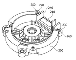
- 3 is a view showing the bottom of the bracket of the housing.
- the bracket 200 may include a second ground portion 210, a third ground portion 220, and a fourth ground portion 230.
- the bracket 200 may include an accommodation part 240 for receiving the wire assembly 50.
- the receptacle 240 secures a space where the grommets 52 of the wire assembly 50 are inserted.
- the bracket 200 may include a first fastening hole 250 and a second fastening hole 260.
- the first fastening hole 250 is a place that is fastened to the body 100 of the housing 40.
- the second fastening hole 260 is a place where the EPS system is fastened.
- a plurality of first fastening holes 250 and second fastening holes 260 may be disposed.
- any one of the plurality of first fastening holes 250 may be disposed on any one side of the accommodating part 240 based on the accommodating part 240.
- Any one of the plurality of second fastening holes 260 may be disposed on the other side of the receiving part 240.
- FIG. 4 is a view showing a ground portion of the bracket.
- the second ground portion 210, the third ground portion 220, and the fourth ground portion 230 may be described separately according to their shape and functional characteristics. It may be one member connected to each other up and down.
- the second ground portion 210, the third ground portion 220, and the fourth ground portion 230 may be made of a conductive metal material.
- the second ground portion 210, the third ground portion 220, and the fourth ground portion 230 may be coupled to the bracket 200 by double injection.
- the second ground portion 210 may have a flat plate shape.
- the second ground portion 210 is disposed in the accommodation portion 240.
- the second ground portion 210 may be disposed to be exposed to the outside from the bottom surface of the bracket 200.
- the second ground portion 210 is in contact with the first ground portion 53 of the wire assembly 50 positioned in the receiving portion 240.
- the third grounding part 220 may be a cylindrical member having a hole 221 through which the fastening member penetrates in the center.
- the hole 221 penetrates a fastening member for coupling the bracket 200 and the body 100.
- the third ground part 220 may be inserted into the first fastening hole 250.
- the first fastening hole 250 is a place where the body 100 is essentially in contact with the body 100 to couple the bracket 200.
- the third grounding part 220 is disposed in the first fastening hole 250 to implement a grounding configuration for EMI shielding. Therefore, it is not necessary to provide a separate grounding configuration for contacting the third grounding part 220 and the body 100.
- the third ground part 220 may be disposed on either side of the second ground part 210.
- the fourth grounding part 230 may be a cylindrical member in which a hole 231 through which the fastening member penetrates is disposed in the center.
- the hole 231 penetrates a fastening member for coupling the bracket 200 to the EPS system.
- the fourth ground part 230 may be inserted into the second fastening hole 260.
- the second fastening hole 260 is essentially in contact with the EPS system in order to couple the bracket 200 to the EPS system.
- the fourth grounding part 230 is disposed in the second fastening hole 260 to implement a grounding configuration for EMI shielding. Therefore, it is not necessary to provide a separate grounding configuration for contacting the fourth grounding portion 230 and the EPS system.
- the fourth ground portion 230 may be disposed on the other side of the second ground portion 210.
- FIG. 5 is a front view of a grounding part of the bracket shown in FIG. 4.
- the third ground portion 220 and the fourth ground portion 230 may be disposed at different positions in the height direction (z-axis direction) with respect to the second ground portion 210. have. This is where the third grounding part 220 is in contact with the body 100 of the housing 40. The position at which the fourth grounding portion 230 is in contact with an external device such as an EPS system is considered.
- FIG. 6 is a side cross-sectional view of a bracket including a grounding part.
- the first ground portion 53 of the wire assembly 50 contacts the second ground portion 210.
- the lower surface 222 of the third grounding part 220 is grounded in contact with the upper end of the body 100.
- the first ground portion 53 of the wire assembly 50 is in contact with the second ground portion 210 and the third ground portion 220 is in contact with the body 100.
- the top surface 232 of the fourth grounding portion 230 is grounded in contact with the EPS system. Therefore, even in the bracket 200 made of a plastic resin that is not energized, EMI can be shielded.
- FIG. 7 is an exploded view of a motor according to another embodiment
- FIG. 8 is a view showing a wire assembly mounted on the top of the body of the housing in the motor shown in FIG. 7.
- the wire assembly 50 is seated on the top surface of the body 1100.
- the bracket 1200 may include a receiving portion 1210 for receiving the wire assembly 50.
- the receiving part 1210 secures a space into which the grommets 400 of the wire assembly 50 are inserted.
- the wire assembly 50 may include a hole 410.
- the hole 410 is disposed on the bottom surface of the grommets 400.
- Three holes 410 may be disposed corresponding to three cables 300.
- the three holes 410 may be aligned along the width direction (x-axis direction of FIG. 9) of the grommet 400.
- FIG. 10 is a side cross-sectional view showing the interior of the grommets of the wire assembly.
- the grommets 400 of the wire assembly 50 receive the cable 300 therein.
- the cable 300 may include a core 310, an insulating layer 320, a shield layer 330, and a coating layer 340.
- the core 310 refers to a metal part for flowing a current.
- the insulating layer 320 is disposed outside the core 310 to cover the core 310 to withstand the voltage used and to fix the core.
- the shield layer 330 is disposed outside the insulating layer 320 to block the influence of an electric field or a magnetic field, and may be made of a copper wire woven into a mesh.
- the tip end of the cable 300 is disposed inside the grommet 400 so that the covering layer 340 is peeled off and the shield layer 330 is exposed.
- the hole 410 is formed to penetrate from the lower surface of the grommet 400 to the receiving position of the cable 300.
- the shield layer 330 of the cable 300 is disposed to be exposed to the hole 410.
- the body 1100 of the housing 40 may include an extension 1110.
- the extension 1110 may extend outward from the top of the body 1100.
- the protrusion 1120 is disposed in the extension 1110.
- the protrusion 1120 protrudes upward from the extension 1110 and fits into the hole 410 of the grommets 400.
- FIG. 8 when the wire assembly 50 is seated on the extension 1110 at the upper portion of the extension 1110, the protrusion 1120 is fitted into the hole 410, and thus the body 1100 and the body 1100.
- the wire assembly 50 is fixed. Therefore, the coupling force between the body 1100 and the wire assembly 50 can be greatly increased without a separate coupling configuration.
- the protrusion 1120 contacts the shield layer 330 of the cable 300 while being fitted into the hole 410. Since the body 1100 and the shield layer 330 of the cable 300 are electrically connected through the protrusion 1120, there is no need to provide a separate gasket for EMI shielding. Therefore, there is an advantage that the grounding configuration of the motor can be simplified.
- Three protrusions 1120 may be provided to correspond to the number of holes 410. Each protrusion 1120 contacts each of the shield layers 330 of the three cables 300.
- the grommets 400 may include a lower cover portion 420 and an upper cover portion 430.
- the lower cover part 420 protrudes from the lower surface of the grommets 400 and contacts the side surface of the extension part 1110, as shown in FIG. 10A.
- the lower cover part 420 serves to prevent water or foreign matter from flowing into the gap between the lower surface of the grommets 400 and the extension part 1110.
- the lower cover part 420 covers a boundary between the lower surface of the grommets 400 and the extension part 1110, thereby physically preventing water or foreign matter from flowing into the hole 410 or the motor.
- the upper cover part 430 protrudes from the upper surface of the grommets 400 and contacts the side surface of the bracket 1200.
- the upper cover part 430 covers a boundary between the upper surface of the grommets 400 and the bracket 1200, thereby physically preventing water or foreign matter from flowing into the motor.
- 11 is a side view of the body.
- the hole 410 may be long.
- the hole 410 may have a larger width W based on the width direction of the grommet 400 than the length L based on the length direction of the grommet 400 (the y-axis direction of FIG. 9). .
Landscapes
- Engineering & Computer Science (AREA)
- Power Engineering (AREA)
- Physics & Mathematics (AREA)
- Electromagnetism (AREA)
- Chemical & Material Sciences (AREA)
- Combustion & Propulsion (AREA)
- Transportation (AREA)
- Mechanical Engineering (AREA)
- Motor Or Generator Frames (AREA)
Priority Applications (4)
| Application Number | Priority Date | Filing Date | Title |
|---|---|---|---|
| JP2019542381A JP7162602B2 (ja) | 2017-02-06 | 2018-02-06 | モーター |
| US16/483,867 US11336153B2 (en) | 2017-02-06 | 2018-02-06 | Motor |
| EP18748194.0A EP3579389A4 (en) | 2017-02-06 | 2018-02-06 | ENGINE |
| CN201880010508.6A CN110268606B (zh) | 2017-02-06 | 2018-02-06 | 电机 |
Applications Claiming Priority (4)
| Application Number | Priority Date | Filing Date | Title |
|---|---|---|---|
| KR10-2017-0016230 | 2017-02-06 | ||
| KR1020170016230A KR20180091279A (ko) | 2017-02-06 | 2017-02-06 | 모터 |
| KR10-2017-0018074 | 2017-02-09 | ||
| KR1020170018074A KR20180092423A (ko) | 2017-02-09 | 2017-02-09 | 모터 |
Publications (1)
| Publication Number | Publication Date |
|---|---|
| WO2018143764A1 true WO2018143764A1 (ko) | 2018-08-09 |
Family
ID=63039932
Family Applications (1)
| Application Number | Title | Priority Date | Filing Date |
|---|---|---|---|
| PCT/KR2018/001554 WO2018143764A1 (ko) | 2017-02-06 | 2018-02-06 | 모터 |
Country Status (5)
| Country | Link |
|---|---|
| US (1) | US11336153B2 (zh) |
| EP (1) | EP3579389A4 (zh) |
| JP (1) | JP7162602B2 (zh) |
| CN (1) | CN110268606B (zh) |
| WO (1) | WO2018143764A1 (zh) |
Families Citing this family (3)
| Publication number | Priority date | Publication date | Assignee | Title |
|---|---|---|---|---|
| US11031839B2 (en) * | 2016-03-31 | 2021-06-08 | Nidec Corporation | Motor and method of manufacturing motor |
| CN111146894B (zh) * | 2019-12-12 | 2021-10-15 | 武汉理工大学 | 一种组合式碳纤维复合材料吸振电机外壳及其制作方法 |
| TWI756940B (zh) * | 2020-11-26 | 2022-03-01 | 威剛科技股份有限公司 | 馬達端蓋及馬達 |
Citations (5)
| Publication number | Priority date | Publication date | Assignee | Title |
|---|---|---|---|---|
| US6987338B1 (en) * | 2003-12-29 | 2006-01-17 | Lavasser Leonard J | Ground strap for a motor having a plastic housing |
| KR101527679B1 (ko) * | 2014-02-12 | 2015-06-12 | 엘에스메카피온 주식회사 | 터미널 블록 유닛 및 이를 포함하는 모터 |
| KR20150077867A (ko) * | 2013-12-30 | 2015-07-08 | (주) 보쉬전장 | 차량의 프런트 와이퍼용 모터의 트랜스미션 하우징 내의 인쇄 회로 기판에 구비된 브러시 홀더의 접지 구조 |
| KR20160137009A (ko) * | 2015-05-22 | 2016-11-30 | 뉴모텍(주) | 하우징 고정 구조와 접지 구조가 개선된 모터 |
| KR20170011144A (ko) * | 2015-07-21 | 2017-02-02 | 엘지이노텍 주식회사 | 터미널 조립체 및 이를 포함하는 모터 |
Family Cites Families (22)
| Publication number | Priority date | Publication date | Assignee | Title |
|---|---|---|---|---|
| US4656378A (en) * | 1985-11-12 | 1987-04-07 | Amp Incorporated | Motor stator and connector for making connections to stator windings |
| JPH047661Y2 (zh) * | 1986-08-20 | 1992-02-27 | ||
| US5596237A (en) * | 1994-03-31 | 1997-01-21 | Emerson Electric Co. | Ground wire attachment for a motor end-shield |
| JP2000116055A (ja) | 1998-10-05 | 2000-04-21 | Matsushita Electric Ind Co Ltd | シールド線付モータ |
| DE19858207C2 (de) | 1998-12-17 | 2003-02-13 | Fhp Motors Gmbh | Schutzleiteranschluß für Elektromotoren |
| US6528913B1 (en) * | 1999-11-19 | 2003-03-04 | Emerson Electric Co. | Electric device grounding system |
| JP2002165405A (ja) | 2000-11-27 | 2002-06-07 | Hitachi Car Eng Co Ltd | 電動機のシール構造 |
| JP3952439B2 (ja) * | 2001-03-26 | 2007-08-01 | 矢崎総業株式会社 | 電磁波シールド構造 |
| CN1299416C (zh) | 2001-12-25 | 2007-02-07 | 乐金电子(天津)电器有限公司 | 电动机用复合型电源连接器 |
| JP3696556B2 (ja) * | 2002-02-12 | 2005-09-21 | アスモ株式会社 | モータ |
| JP3966407B2 (ja) * | 2002-09-24 | 2007-08-29 | 矢崎総業株式会社 | 防油水性を備えた電磁波シールド構造 |
| JP4274473B2 (ja) * | 2004-06-14 | 2009-06-10 | ミネベア株式会社 | アクチュエータ |
| JP5103845B2 (ja) | 2006-09-26 | 2012-12-19 | 日本電産株式会社 | レゾルバおよびモータ |
| JP5582871B2 (ja) | 2010-05-25 | 2014-09-03 | 三菱電機株式会社 | インバータ駆動モータ |
| JP5624805B2 (ja) * | 2010-06-10 | 2014-11-12 | 矢崎総業株式会社 | シールド端末接続構造及び方法 |
| DE102012103928A1 (de) * | 2012-05-04 | 2013-11-07 | Pierburg Gmbh | Gleichstrommotor zum Antrieb von Aggregaten eines Kraftfahrzeugs |
| JP5970355B2 (ja) * | 2012-11-28 | 2016-08-17 | 日本航空電子工業株式会社 | ステータ |
| JP5915939B2 (ja) * | 2013-01-16 | 2016-05-11 | 住友電装株式会社 | グロメット保護部材及び電線接続装置 |
| KR101442414B1 (ko) | 2013-05-23 | 2014-09-24 | 뉴모텍(주) | 모터 접지구조 |
| NO2683824T3 (zh) * | 2014-09-10 | 2018-09-22 | ||
| JP6528501B2 (ja) * | 2015-03-26 | 2019-06-12 | 日本電産株式会社 | モータおよびファン |
| KR102485025B1 (ko) * | 2015-09-14 | 2023-01-05 | 엘지이노텍 주식회사 | 일체형 케이블 및 이를 포함하는 모터 어셈블리 |
-
2018
- 2018-02-06 CN CN201880010508.6A patent/CN110268606B/zh active Active
- 2018-02-06 US US16/483,867 patent/US11336153B2/en active Active
- 2018-02-06 WO PCT/KR2018/001554 patent/WO2018143764A1/ko active Application Filing
- 2018-02-06 EP EP18748194.0A patent/EP3579389A4/en active Pending
- 2018-02-06 JP JP2019542381A patent/JP7162602B2/ja active Active
Patent Citations (5)
| Publication number | Priority date | Publication date | Assignee | Title |
|---|---|---|---|---|
| US6987338B1 (en) * | 2003-12-29 | 2006-01-17 | Lavasser Leonard J | Ground strap for a motor having a plastic housing |
| KR20150077867A (ko) * | 2013-12-30 | 2015-07-08 | (주) 보쉬전장 | 차량의 프런트 와이퍼용 모터의 트랜스미션 하우징 내의 인쇄 회로 기판에 구비된 브러시 홀더의 접지 구조 |
| KR101527679B1 (ko) * | 2014-02-12 | 2015-06-12 | 엘에스메카피온 주식회사 | 터미널 블록 유닛 및 이를 포함하는 모터 |
| KR20160137009A (ko) * | 2015-05-22 | 2016-11-30 | 뉴모텍(주) | 하우징 고정 구조와 접지 구조가 개선된 모터 |
| KR20170011144A (ko) * | 2015-07-21 | 2017-02-02 | 엘지이노텍 주식회사 | 터미널 조립체 및 이를 포함하는 모터 |
Non-Patent Citations (1)
| Title |
|---|
| See also references of EP3579389A4 * |
Also Published As
| Publication number | Publication date |
|---|---|
| JP2020506657A (ja) | 2020-02-27 |
| EP3579389A4 (en) | 2021-03-10 |
| US20200014286A1 (en) | 2020-01-09 |
| CN110268606A (zh) | 2019-09-20 |
| CN110268606B (zh) | 2021-11-19 |
| EP3579389A1 (en) | 2019-12-11 |
| US11336153B2 (en) | 2022-05-17 |
| JP7162602B2 (ja) | 2022-10-28 |
Similar Documents
| Publication | Publication Date | Title |
|---|---|---|
| WO2018199573A1 (ko) | 모터 | |
| WO2017119584A1 (ko) | 모터 및 이를 포함하는 전동식 조향장치 | |
| WO2018143764A1 (ko) | 모터 | |
| WO2017217729A1 (ko) | 로터 및 이를 포함하는 모터 | |
| WO2016076599A1 (ko) | 모터 | |
| WO2016111539A1 (ko) | 모터 | |
| WO2019156440A1 (ko) | 모터 | |
| WO2014163293A1 (en) | Motor with simple assembling sensor magnet | |
| WO2012064103A2 (ko) | 더블 로터 타입 모터 | |
| WO2016122201A1 (en) | Motor | |
| WO2013151231A1 (en) | Hall sensor cover and motor using the same | |
| WO2018026177A1 (ko) | 리어 홀더 및 이를 포함하는 모터 | |
| WO2020145645A1 (ko) | 모터 | |
| WO2019112315A1 (ko) | 냉각 팬 | |
| WO2020055067A1 (ko) | 모터 | |
| WO2019050199A1 (ko) | 모터 | |
| WO2022108292A1 (ko) | 모터 | |
| WO2021107419A1 (ko) | 모터 | |
| WO2019151766A1 (ko) | 모터 | |
| WO2023224282A1 (ko) | 모터 | |
| KR20180092423A (ko) | 모터 | |
| KR102477861B1 (ko) | 모터 및 이를 포함하는 조향 장치 | |
| WO2019088755A1 (ko) | 모터 | |
| WO2018131905A1 (ko) | 모터 | |
| WO2021141362A1 (ko) | 모터 |
Legal Events
| Date | Code | Title | Description |
|---|---|---|---|
| 121 | Ep: the epo has been informed by wipo that ep was designated in this application |
Ref document number: 18748194 Country of ref document: EP Kind code of ref document: A1 |
|
| ENP | Entry into the national phase |
Ref document number: 2019542381 Country of ref document: JP Kind code of ref document: A |
|
| NENP | Non-entry into the national phase |
Ref country code: DE |
|
| WWE | Wipo information: entry into national phase |
Ref document number: 2018748194 Country of ref document: EP |