WO2018143347A1 - Dispositif de source de lumière, dispositif d'affichage de type à projection, procédé d'éclairage et procédé d'affichage - Google Patents
Dispositif de source de lumière, dispositif d'affichage de type à projection, procédé d'éclairage et procédé d'affichage Download PDFInfo
- Publication number
- WO2018143347A1 WO2018143347A1 PCT/JP2018/003414 JP2018003414W WO2018143347A1 WO 2018143347 A1 WO2018143347 A1 WO 2018143347A1 JP 2018003414 W JP2018003414 W JP 2018003414W WO 2018143347 A1 WO2018143347 A1 WO 2018143347A1
- Authority
- WO
- WIPO (PCT)
- Prior art keywords
- light source
- light
- optical system
- incident
- source device
- Prior art date
Links
Images


Classifications
-
- H—ELECTRICITY
- H04—ELECTRIC COMMUNICATION TECHNIQUE
- H04N—PICTORIAL COMMUNICATION, e.g. TELEVISION
- H04N9/00—Details of colour television systems
- H04N9/12—Picture reproducers
- H04N9/31—Projection devices for colour picture display, e.g. using electronic spatial light modulators [ESLM]
- H04N9/3141—Constructional details thereof
- H04N9/315—Modulator illumination systems
- H04N9/3152—Modulator illumination systems for shaping the light beam
-
- G—PHYSICS
- G02—OPTICS
- G02B—OPTICAL ELEMENTS, SYSTEMS OR APPARATUS
- G02B26/00—Optical devices or arrangements for the control of light using movable or deformable optical elements
- G02B26/007—Optical devices or arrangements for the control of light using movable or deformable optical elements the movable or deformable optical element controlling the colour, i.e. a spectral characteristic, of the light
- G02B26/008—Optical devices or arrangements for the control of light using movable or deformable optical elements the movable or deformable optical element controlling the colour, i.e. a spectral characteristic, of the light in the form of devices for effecting sequential colour changes, e.g. colour wheels
-
- G—PHYSICS
- G03—PHOTOGRAPHY; CINEMATOGRAPHY; ANALOGOUS TECHNIQUES USING WAVES OTHER THAN OPTICAL WAVES; ELECTROGRAPHY; HOLOGRAPHY
- G03B—APPARATUS OR ARRANGEMENTS FOR TAKING PHOTOGRAPHS OR FOR PROJECTING OR VIEWING THEM; APPARATUS OR ARRANGEMENTS EMPLOYING ANALOGOUS TECHNIQUES USING WAVES OTHER THAN OPTICAL WAVES; ACCESSORIES THEREFOR
- G03B21/00—Projectors or projection-type viewers; Accessories therefor
- G03B21/005—Projectors using an electronic spatial light modulator but not peculiar thereto
- G03B21/008—Projectors using an electronic spatial light modulator but not peculiar thereto using micromirror devices
-
- G—PHYSICS
- G03—PHOTOGRAPHY; CINEMATOGRAPHY; ANALOGOUS TECHNIQUES USING WAVES OTHER THAN OPTICAL WAVES; ELECTROGRAPHY; HOLOGRAPHY
- G03B—APPARATUS OR ARRANGEMENTS FOR TAKING PHOTOGRAPHS OR FOR PROJECTING OR VIEWING THEM; APPARATUS OR ARRANGEMENTS EMPLOYING ANALOGOUS TECHNIQUES USING WAVES OTHER THAN OPTICAL WAVES; ACCESSORIES THEREFOR
- G03B21/00—Projectors or projection-type viewers; Accessories therefor
- G03B21/14—Details
- G03B21/20—Lamp housings
- G03B21/2006—Lamp housings characterised by the light source
- G03B21/2013—Plural light sources
-
- G—PHYSICS
- G03—PHOTOGRAPHY; CINEMATOGRAPHY; ANALOGOUS TECHNIQUES USING WAVES OTHER THAN OPTICAL WAVES; ELECTROGRAPHY; HOLOGRAPHY
- G03B—APPARATUS OR ARRANGEMENTS FOR TAKING PHOTOGRAPHS OR FOR PROJECTING OR VIEWING THEM; APPARATUS OR ARRANGEMENTS EMPLOYING ANALOGOUS TECHNIQUES USING WAVES OTHER THAN OPTICAL WAVES; ACCESSORIES THEREFOR
- G03B21/00—Projectors or projection-type viewers; Accessories therefor
- G03B21/14—Details
- G03B21/20—Lamp housings
- G03B21/2006—Lamp housings characterised by the light source
- G03B21/2033—LED or laser light sources
- G03B21/204—LED or laser light sources using secondary light emission, e.g. luminescence or fluorescence
-
- G—PHYSICS
- G03—PHOTOGRAPHY; CINEMATOGRAPHY; ANALOGOUS TECHNIQUES USING WAVES OTHER THAN OPTICAL WAVES; ELECTROGRAPHY; HOLOGRAPHY
- G03B—APPARATUS OR ARRANGEMENTS FOR TAKING PHOTOGRAPHS OR FOR PROJECTING OR VIEWING THEM; APPARATUS OR ARRANGEMENTS EMPLOYING ANALOGOUS TECHNIQUES USING WAVES OTHER THAN OPTICAL WAVES; ACCESSORIES THEREFOR
- G03B21/00—Projectors or projection-type viewers; Accessories therefor
- G03B21/14—Details
- G03B21/20—Lamp housings
- G03B21/2066—Reflectors in illumination beam
-
- G—PHYSICS
- G03—PHOTOGRAPHY; CINEMATOGRAPHY; ANALOGOUS TECHNIQUES USING WAVES OTHER THAN OPTICAL WAVES; ELECTROGRAPHY; HOLOGRAPHY
- G03B—APPARATUS OR ARRANGEMENTS FOR TAKING PHOTOGRAPHS OR FOR PROJECTING OR VIEWING THEM; APPARATUS OR ARRANGEMENTS EMPLOYING ANALOGOUS TECHNIQUES USING WAVES OTHER THAN OPTICAL WAVES; ACCESSORIES THEREFOR
- G03B21/00—Projectors or projection-type viewers; Accessories therefor
- G03B21/14—Details
- G03B21/20—Lamp housings
- G03B21/208—Homogenising, shaping of the illumination light
-
- H—ELECTRICITY
- H04—ELECTRIC COMMUNICATION TECHNIQUE
- H04N—PICTORIAL COMMUNICATION, e.g. TELEVISION
- H04N9/00—Details of colour television systems
- H04N9/12—Picture reproducers
- H04N9/31—Projection devices for colour picture display, e.g. using electronic spatial light modulators [ESLM]
- H04N9/3141—Constructional details thereof
- H04N9/315—Modulator illumination systems
- H04N9/3158—Modulator illumination systems for controlling the spectrum
-
- H—ELECTRICITY
- H04—ELECTRIC COMMUNICATION TECHNIQUE
- H04N—PICTORIAL COMMUNICATION, e.g. TELEVISION
- H04N9/00—Details of colour television systems
- H04N9/12—Picture reproducers
- H04N9/31—Projection devices for colour picture display, e.g. using electronic spatial light modulators [ESLM]
- H04N9/3141—Constructional details thereof
- H04N9/315—Modulator illumination systems
- H04N9/3161—Modulator illumination systems using laser light sources
-
- H—ELECTRICITY
- H04—ELECTRIC COMMUNICATION TECHNIQUE
- H04N—PICTORIAL COMMUNICATION, e.g. TELEVISION
- H04N9/00—Details of colour television systems
- H04N9/12—Picture reproducers
- H04N9/31—Projection devices for colour picture display, e.g. using electronic spatial light modulators [ESLM]
- H04N9/3141—Constructional details thereof
- H04N9/315—Modulator illumination systems
- H04N9/3164—Modulator illumination systems using multiple light sources
-
- G—PHYSICS
- G02—OPTICS
- G02B—OPTICAL ELEMENTS, SYSTEMS OR APPARATUS
- G02B13/00—Optical objectives specially designed for the purposes specified below
- G02B13/22—Telecentric objectives or lens systems
Definitions
- the present invention relates to a light source device, a projection display device, an illumination method, and a display method.
- Patent Document 1 describes a projection display device using a solid light source.
- the projection display device includes first and second light source units, a rod integrator, a display element, and a projection lens.
- the display element is a DMD (digital micromirror device), and has an image forming surface composed of a plurality of micromirrors arranged two-dimensionally.
- the rod integrator includes a rectangular column light guide (solid).
- One of both end faces of the light guide is an incident surface, and the other is an exit surface. Light incident from the incident surface propagates through the light guide unit while being repeatedly reflected, and is emitted from the exit surface.
- the shape of the exit surface of the light guide is similar to the shape of the image forming surface of the display element.
- Both the first and second light source units are solid light sources, and emit light of the same color.
- the output light of the first light source unit enters the first region of the entrance surface of the rod integrator via the first optical system.
- the output light of the second light source unit is incident on a second region different from the first region on the incident surface of the rod integrator via the second optical system.
- a light source image of the first light source unit is formed in the first region, and a light source image of the second light source unit is formed in the second region.
- the light beam emitted from the exit surface of the rod integrator enters the display element.
- an image is formed by modulating an incident light beam by each micromirror based on an input video signal.
- the projection lens projects an image of each color formed on the display element on the screen.
- the luminous intensity is increased by combining the light beams from the two light source units with a rod integrator.
- the projection display device there is a restriction called etendue defined by the product of the cross-sectional area of the light beam and the divergence angle (solid angle determined by light).
- etendue defined by the product of the cross-sectional area of the light beam and the divergence angle (solid angle determined by light).
- the etendue on the irradiation side is given by the product (multiplication) of the area of the light source and the divergence angle of the light emitted from the light source
- the etendue on the taking side is the area of the display element and the F number of the projection lens. It is given by the product (multiplication value) with the capture angle (solid angle) determined by.
- the etendue on the irradiation side is given by the product of the area of the surface light source formed on the exit surface of the rod integrator and the divergence angle of the light beam emitted from the exit surface.
- the acquisition-side etendue is given by the product of the area of the image forming surface of the display element and the capture angle (solid angle) determined by the F-number of the projection lens.
- the projection display device described in Patent Document 1 has the following problems.
- Light source images of the first and second light source units are formed in the first and second regions of the entrance surface of the rod integrator, respectively, but the sizes of these light source images are different, and the output light of each light source unit The angle of incorporation (solid angle) into each region is also different. For this reason, luminance unevenness occurs in the light beam emitted from the rod integrator.
- the relationship between the size and interval of the light source image of each light source unit formed on the incident surface of the rod integrator and the etendue is not considered. For this reason, even if the size of the light source image of each light source unit is made the same, the light utilization efficiency in the optical system after the rod integrator may be lowered.
- An object of the present invention is to provide a light source device, a projection display device, an illumination method, and a display method capable of solving the above-described problems and improving the light utilization efficiency.
- a first light source device of the present invention comprises: First and second light sources; A first optical system that images the light source images of the first and second light sources in different regions on the same imaging plane, The first optical system includes: A first reflecting surface that reflects the first light beam from the first light source toward the imaging surface, and a second reflecting surface that reflects the second light beam from the second light source toward the imaging surface.
- a reflective element comprising: 2 reflective surfaces; When viewed from a direction perpendicular to a plane orthogonal to the first and second reflecting surfaces, an apex angle portion that is a joint portion of the first and second reflecting surfaces is incident on the first reflecting surface.
- the first light flux and the second light flux incident on the second reflecting surface are disposed inside the outermost peripheral portion.
- the second light source device of the present invention comprises: First and second light sources; A first optical system that images the light source images of the first and second light sources in different regions on the same imaging plane,
- the first optical system includes: A first reflecting surface that reflects the first light beam from the first light source toward the imaging surface, and a second reflecting surface that reflects the second light beam from the second light source toward the imaging surface.
- a reflective element comprising: 2 reflective surfaces; Part of the first light flux is not reflected by the first reflecting surface, A part of the second light flux is configured not to be reflected by the second reflecting surface.
- the projection display device of the present invention includes the first or second light source device described above, A display element that modulates the light output from the light source device to form an image; A projection lens that projects an image formed by the display element.
- the illumination method of the present invention is an illumination method using first and second light sources,
- the first light flux from the first light source is reflected by the first reflecting surface of the reflecting element toward the imaging surface,
- a second light flux from the second light source is reflected by the second reflecting surface of the reflecting element toward the imaging surface;
- an apex angle portion that is a joint portion of the first and second reflecting surfaces is incident on the first reflecting surface.
- the first light flux and the second light flux incident on the second reflecting surface are disposed inside the outermost peripheral portion.
- the display method of the present invention includes: Having the illumination method, A light beam from a combined light source composed of light source images of the first and second light sources formed on the imaging surface is incident on the integrator, Modulating the light from the integrator to form an image, Projecting the formed image.
- the light use efficiency can be increased.
- FIG. 1 is a schematic diagram showing a configuration of a light source device according to a first embodiment of the present invention.
- the light source device is a light source device used in a projection display device, and includes first and second surface light sources 50a and 50b, a first optical system 51, a second optical system 56, and an optical device. An element 57 is included.
- the first and second surface light sources 50a and 50b have the same structure and have a light emitting surface of a predetermined shape (here, square).
- the first surface light source 50a can be referred to as a first light source.
- the second surface light source 50b can be referred to as a second light source.
- the optical element 57 can be called an integrator.
- an integrator a fly-eye lens, a rod, a light tunnel, or the like can be used.
- the optical element 57 is composed of a rod or a light tunnel.
- the optical element 57 includes a prismatic light guide portion 57a.
- One of the both end faces of the light guide portion 57a is the entrance surface 57b, and the other is the exit surface 57c.
- the light incident from the incident surface 57b propagates through the light guide portion 57a while being repeatedly reflected and is emitted from the emission surface 57c.
- a uniform surface light source can be formed on the emission surface 57c by being reflected a plurality of times inside the light guide portion 57a.
- the first optical system 51 forms the light source images of the first and second surface light sources 50 a and 50 b in different regions on the first imaging surface 55.
- the first optical system 51 includes a reflecting element 53, a first both-side telecentric optical system 52a, and a second both-side telecentric optical system 52b.
- the both-side telecentric optical system means a telecentric optical system in which the optical axis and the principal ray are parallel on both the object side and the image side.
- the reflective element 53 includes first and second reflective surfaces 53a and 53b provided so as to be perpendicular to each other.
- the first both-side telecentric optical system 52a is provided on the optical path between the first surface light source 50a and the first reflection surface 53a, and the light source image of the first surface light source 50a is displayed on the first reflection surface.
- An image is formed on the first image plane 55 via 53a.
- the second both-side telecentric optical system 52b is provided on the optical path between the second surface light source 50b and the second reflection surface 53b, and the light source image of the second surface light source 50b is used as the second reflection surface.
- An image is formed on the first image plane 55 via 53b.
- the first both-side telecentric optical system 52 a and the second both-side telecentric optical system 52 b have the same structure, and are arranged so that their emission surfaces face each other with the reflective element 53 interposed therebetween.
- the principal ray (optical axis) of the first light beam from the first both-side telecentric optical system 52a and the principal ray (optical axis) of the second light beam from the second both-side telecentric optical system 52b are on the same axis. I'm doing it.
- the virtual imaging plane 54 indicates an imaging plane in the state where the first and second reflecting surfaces 53a and 53b are not interposed in the first both-side telecentric optical system 52a and the second both-side telecentric optical system 52b, respectively.
- the virtual imaging plane 54 and the first imaging plane 55 are orthogonal to each other.
- the angle formed between the first reflecting surface 53a and the virtual imaging surface 54 is 45 °, and the angle formed between the principal ray of the light beam from the first both-side telecentric optical system 52a and the first reflecting surface 53a is 45 °. It is.
- the angle formed between the second reflecting surface 53b and the virtual imaging surface 54 is 45 °, and the angle formed between the principal ray of the light beam from the second both-side telecentric optical system 52b and the second reflecting surface 53b. Is also 45 °.
- the first reflecting surface 53a and the second reflecting surface 53b reflect the first light beam from the first both-side telecentric optical system 52a and the second light beam from the second both-side telecentric optical system 52b in the same direction. .
- the first both-side telecentric optical system 52a, the second both-side telecentric optical system 52b, and the reflecting element 53 are arranged so that the combined surface light source has a predetermined shape (for example, an aspect ratio).
- the predetermined shape is a shape that can improve the light utilization efficiency in the optical system after the optical element 57 in consideration of etendue.
- the shape (aspect ratio) of the exit surface 57c of the light guide portion 57a substantially matches the shape (aspect ratio) of the image forming surface.
- the principal ray of the first light beam from the first both-side telecentric optical system 52a and the principal ray of the second light beam from the second both-side telecentric optical system 52b are located on the same axis.
- the apex angle portion which is the junction of the first and second reflecting surfaces 53a, 53b, is You may arrange
- the second optical system 56 forms an image on the incident surface 57b of the light guide portion 57a with a combined surface light source composed of light source images of the first and second surface light sources formed on the first image forming surface 55. To do.
- the second optical system 56 may include a third double-sided telecentric lens optical system.
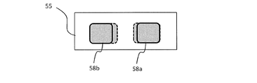
- FIG. 2 schematically shows light source images of the first and second surface light sources 50a and 50b formed on the first imaging surface 55.
- a light source image 58a is a light source image of the first surface light source 50a
- a light source image 58b is a light source image of the second surface light source 50b.
- the light source images 58a and 58b have a line-symmetric shape.
- the light source images 58a and 58b are formed at an interval d.
- the combined surface light source 58 includes light source images 58a and 58b.
- a ratio (H: V) of the horizontal size H and the vertical size V of the combined surface light source 58 is the aspect ratio.
- this aspect ratio is a predetermined aspect that can improve the light utilization efficiency in the optical system after the optical element 57.
- the light source device of this embodiment when applied to a projection display device, there is an effect that the light use efficiency is improved.
- the reflective element 53 can be configured by a V-shaped mirror or a right-angle prism.
- FIG. 3 schematically shows a V-shaped mirror that is an example of the reflective element 53.
- the V-shaped mirror is composed of two reflecting portions 60a and 60b provided so that the reflecting surfaces thereof are perpendicular to each other.
- Each of the reflecting portions 60a and 60b has a reflecting surface formed on the surface opposite to the virtual imaging surface 54 side.
- the reflecting surface and the virtual imaging surface 54 (or the first imaging surface 55) The angle formed is 45 °.
- FIG. 4 schematically shows changes in the light source images 58 a and 58 b when the V-shaped mirror is moved in the direction perpendicular to the first image plane 55.
- the solid line arrow A1 indicates the optical axis (the principal ray of the first light beam) of the first double-sided telecentric optical system 52a
- the solid line arrow A2 indicates the optical axis (first line of the second double-sided telecentric optical system 52b. 2 is the principal ray of the two luminous fluxes.
- Reference numerals Z1 and Z2 denote distances from the intersection with the optical axis A1 on the reflection surface of the reflection part 60a to the virtual imaging plane 54, and reference numerals Z1 ′ and Z2 ′ denote optical axes on the reflection surface of the reflection part 60a.
- the distance from the intersection with A1 to the first image plane 55 is shown.
- the reflecting element 53 When the reflecting element 53 is moved in a direction perpendicular to the first image plane 55, the following conditions are satisfied. (1) The incident angles of the first and second light beams on the reflecting portions 60a and 60b (or the first image plane 55) do not change. (2) The imaging performance of the first and second surface light sources 50a and 50b on the first imaging surface 55 does not change. (3) When vignetting occurs at the apex portion, the areas of the light source images 58a and 58b are reduced. (4) The horizontal width H of the composite surface light source 58 and the distance D between the light source images 58a and 58b are proportional to twice the vertical movement amount of the reflective element 53.
- the first double-sided telecentric optical system 52a and the second two-sided optical system 58a have a predetermined shape that can improve the light use efficiency in the optical system after the optical element 57.
- a telecentric optical system 52b and a reflective element 53 are disposed.
- the reflective element 53 is arranged so that vignetting occurs in the first and second light beams at the apex angles of the reflecting portions 60a and 60b.
- FIG. 5 schematically shows a combined surface light source 58 formed on the first imaging surface 55 when the reflective element 53 is arranged so that vignetting occurs in the first and second light beams.
- the distance D between the light source images 58a and 58b can be made as small as possible.
- the synthetic surface light source 58 into a predetermined shape and reducing the distance D between the light source images 58a and 58b, it is possible to minimize the degradation of light utilization efficiency due to etendue restrictions, and as a result. , High luminance can be achieved.
- F no 2.40486 ( ⁇ F / 2.4) according to the above equation 1.
- Fno the brightness changes with the square of the ratio of the change. Since the current 1.38 type DMD is F / 2.5 ( ⁇ 11.5 ° or less), F / 2.5 will be described below as an example.
- A is the area of the DMD (area of the image forming surface)
- ⁇ the deflection angle of the micromirror.
- vignetting is generated as shown in FIG. 5 in order to minimize degradation of light utilization efficiency.
- This etendue value of 67.5 is close to the etendue value of 63.54.
- E 94.5, which is far from the above-mentioned etendue value of 63.54.
- FIG. 6 schematically shows a right-angle prism which is another example of the reflective element 53.
- the right-angle prism 61 has reflection surfaces 61a and 61b that are perpendicular to each other.
- the angle formed by the reflecting surface 61a and the virtual imaging surface 54 (or the first imaging surface 55) is 45 °.
- the angle formed by the reflecting surface 61b and the virtual imaging surface 54 (or the first imaging surface 55) is also 45 °.
- FIG. 7 schematically shows changes in the light source images 58 a and 58 b when the right-angle prism 61 is moved in a direction perpendicular to the first image plane 55.
- the solid line arrow A1 indicates the optical axis (the principal ray of the first light beam) of the first double-sided telecentric optical system 52a
- the solid line arrow A2 indicates the optical axis (first line of the second double-sided telecentric optical system 52b. 2 is the principal ray of the two luminous fluxes.
- Reference numerals Z1 and Z2 denote distances from the intersection with the optical axis A1 on the reflecting surface 61a to the virtual imaging plane 54, and reference signs Z1 ′ and Z2 ′ denote the first from the intersection with the optical axis A1 on the reflecting surface 61a.
- a distance to one image plane 55 is shown.
- 61 is arranged. Specifically, the right-angle prism 61 is arranged so that vignetting occurs in the first and second light beams at the apex angles of the reflecting surfaces 61a and 61b. Even when the right-angle prism 61 is used, the same effect as that obtained when the V-shaped mirror is used is obtained.
- FIG. 8A schematically shows the positional relationship between the right angle prism 61 and the apex angle portion of the V-shaped mirror when the composite surface light source 58 is formed so as to have a predetermined shape (size) in a state where vignetting has occurred.
- FIG. 8B schematically shows light source images 58a and 58b formed on the first image plane 55 in the state shown in FIG. 8A.
- the apex angle portion of the right-angle prism 61 is a right angle surface, whereas the apex angle portion of the V-shaped mirror (joint portion of the reflecting portions 60a and 60b) is not a right angle surface. Therefore, as shown in FIG. 8A, in the direction perpendicular to the first image plane 55, the apex angle portion of the right-angle prism 61 is higher than the junction portion of the reflection portions 60a and 60b of the V-shaped mirror by the height d1. Is also located on the first imaging plane 55 side. As a result, as shown in FIG.
- the light source images 58a and 58b (broken line) when the right-angle prism 61 is used are larger than the light source images 58a and 58b (solid line) when the V-shaped mirror is used.
- the size of the combined surface light source 58 does not change between the case where the right-angle prism 61 is used and the case where the V-shaped mirror is used, the light source images 58a and 58b (solid lines) become larger, so that light can be captured more efficiently. Light utilization efficiency can be further improved.
- the first and second surface light sources 50a and 50b and the first and second both-side telecentric optical systems 52a and 52b will be specifically described.
- the first light source part composed of the first surface light source 50a and the first both-side telecentric optical system 52a, and the second light source part composed of the second surface light source 50b and the twelfth both-side telecentric optical system 52b They have the same structure.
- Solid-state light sources can be used as the first and second surface light sources 50a and 50b.
- FIG. 9 shows an example of a light source portion using a solid light source.
- the light source portion includes light source units 1a and 1b, condenser lenses 2a and 2b, reflection mirrors 3a, 3b, 4a and 4b, a diffuser plate 5, a light pipe 6 and lenses 7 to 9.
- the light source unit 1a includes solid light sources 11a and 12a that emit light of the same color and a reflection mirror 13a.
- the solid light sources 11a and 12a have the same structure, and include, for example, a plurality of laser diodes (LDs) that output laser light having a center wavelength in a wavelength region of a predetermined color.
- LDs laser diodes
- the reflection mirror 13a is a mirror having a stripe structure in which reflection areas and transmission areas are alternately arranged.
- a stripe-shaped mirror can be formed by vapor-depositing a band-shaped reflective region on a transparent substrate at a predetermined interval.
- Each row of LDs of the solid-state light source 11a and each transmission region of the reflection mirror 13a have a one-to-one correspondence, and the laser light emitted from the LD of each row passes through the corresponding transmission region of the reflection mirror 13a.
- Each row of LDs of the solid-state light source 12a and each reflection region of the reflection mirror 13a have a one-to-one correspondence.
- the reflected laser beam is reflected in the same direction as the traveling direction.
- the laser light transmitted through the transmission region and the laser light reflected by the reflection region are output light of the light source unit 1a, and this output light is incident on the condenser lens 2a.
- the light source unit 1b outputs light of the same color as the light source unit 1a, and includes solid light sources 11b and 12b and a reflection mirror 13b.
- the portion composed of the solid light sources 11b and 12b and the reflection mirror 13b has the same structure as the portion composed of the solid light sources 11a and 12a and the reflection mirror 13a.
- the laser light emitted from the solid light source 11b is transmitted through each transmission region of the reflection mirror 13b, and the laser light emitted from the solid light source 12b is the same as the traveling direction of the laser light transmitted through the transmission region in each reflection region of the reflection mirror 13b. Reflected in the direction.
- the laser light transmitted through the transmission region and the laser light reflected by the reflection region are output light of the light source unit 1b, and this output light is incident on the condenser lens 2b.
- the laser light that has passed through the condenser lens 2 a passes through the reflecting mirrors 3 a and 4 a and the diffusion plate 5 in order and enters the incident surface of the light pipe 6.
- the laser light that has passed through the condenser lens 2 b passes through the reflecting mirrors 3 b and 4 b and the diffusion plate 5 in order and enters the incident surface of the light pipe 6.
- Each of the light source units 1a and 1b can be called a light source unit.
- the condensing lenses 2a and 2b and the reflecting mirrors 3a, 3b, 4a and 4b can be called light folding means.
- the length of the first optical path from the light source unit 1 a to the incident surface of the light pipe 6 is the same as the length of the second optical path from the light source unit 1 b to the incident surface of the light pipe 6.
- the condensing angle of the condensing lens 2a (the angle given by 2 ⁇ when the angle between the optical axis and the outermost light beam of the light beam is ⁇ ) is the same as that of the condensing lens 2b.
- the incident angle of the central ray of the light beam incident on the incident surface of the light pipe 6 in the first optical path is the same as the incident angle of the central beam of the light beam incident on the incident surface of the light pipe 6 in the second optical path.
- the light pipe 6 is composed of a columnar light guide, and one of both end faces of the light guide is an entrance surface, and the other is an exit surface.
- the light enters the entrance surface, and light propagates through the light guide and exits.
- An optical element (light uniformizing element) emitted from the surface.
- the light is reflected a plurality of times inside the light guide so that a uniform surface light source can be formed on the exit surface.
- the condensing lens 2 a condenses the laser light from the light source unit 1 a and makes it incident on the incident surface of the light pipe 6.
- the condensing lens 2 b condenses the laser light from the light source unit 1 b and makes it incident on the incident surface of the light pipe 6. You may comprise so that the condensing position of each condensing lens 2a, 2b on the entrance plane of the light pipe 6 may become the same.
- the lenses 7 to 9 constitute a bilateral telecentric lens.
- This double-sided telecentric lens is the first double-sided telecentric lens 52a or the second double-sided telecentric lens 52b shown in FIG.
- the space around the light pipe 6 is utilized, and the light source units 1a and 1b are arranged in the space, so that the apparatus can be miniaturized.
- the laser light emitted from each of the light source units 1 a and 1 b is folded back and incident on the incident surface of the light pipe 6. In this way, the apparatus can be miniaturized by folding the optical path.
- the configuration of the light source portion described above includes the light source portion including the first surface light source 50a and the first both-side telecentric lens 52a, the second surface light source 50b, and the second both-side telecentric of the light source device shown in FIG.
- the present invention can be applied to the light source portion composed of the lens 52b.
- the exit surface (opening surface) of the light pipe 6 constitutes a surface light emitting portion, and a light source image of this surface light emitting portion is formed on the first image forming surface 55 as a light source image 58a or 58b.
- Each of the first and second surface light sources 50a and 50b may be a phosphor light source using a phosphor.
- the phosphor light source may include an excitation light source that emits excitation light and a fluorescent unit that includes a phosphor that is excited by the excitation light and emits fluorescence. In this case, the phosphor may emit green fluorescence.
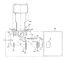
- FIG. 10 shows an example of a light source portion provided with a phosphor light source.
- the light source part includes light source units 21a and 21b, condenser lenses 22a and 22b, reflection mirrors 23a, 23b, 24a, 24b and 34, a diffuser plate 25, a light pipe 26, lenses 27 to 32, and a dichroic mirror. 33 and a fluorescent wheel 35.
- the light source part includes light source units 21a and 21b, condenser lenses 22a and 22b, reflection mirrors 23a, 23b, 24a, 24b and 34, a diffuser plate 25, a light pipe 26, lenses 27 to 32, and a dichroic mirror. 33 and a fluorescent wheel 35.
- FIG. 10 for the sake of convenience, only a part of the ray trajectory is shown.
- the light source units 21a and 21b are excitation light sources for exciting the phosphor, and emit excitation light of the same color.
- the light source unit 21a includes solid light sources 211a and 212a that emit excitation light of the same color and a reflection mirror 213a.
- the solid light sources 211a and 212a have the same structure, and include, for example, a plurality of laser diodes (LDs) that output blue laser light having a center wavelength in a blue wavelength region.
- LDs laser diodes
- (n (rows) ⁇ m (columns)) of blue LDs formed on a holding member provided with a heat radiating portion is used.
- the reflection mirror 213a is a mirror having a stripe structure in which reflection areas and transmission areas are alternately arranged.
- a stripe-shaped mirror can be formed by vapor-depositing a band-shaped reflective region on a transparent substrate at a predetermined interval.
- Each row of blue LDs of the solid-state light source 211a and each transmission region of the reflection mirror 213a have a one-to-one correspondence, and the blue laser light emitted from the blue LD of each row passes through the corresponding transmission region of the reflection mirror 213a. pass.
- Each row of blue LDs of the solid-state light source 212a and each reflection region of the reflection mirror 213a have a one-to-one correspondence, and the blue laser light emitted from the blue LD of each row is reflected by the corresponding reflection region of the reflection mirror 213a.
- the blue laser light that has passed through the transmission region is reflected in the same direction as the traveling direction.
- the blue laser light transmitted through the transmission region and the blue laser light reflected by the reflection region are output light of the light source unit 21a, and this output light is incident on the condenser lens 22a.
- the light source unit 21b includes solid light sources 211b and 212b and a reflection mirror 213b.
- the portion composed of the solid light sources 211b and 212b and the reflection mirror 213b has the same structure as the portion composed of the solid light sources 211a and 212a and the reflection mirror 213a.
- the blue laser light emitted from the solid light source 211b is transmitted through each transmission region of the reflection mirror 213b, and the blue laser light emitted from the solid light source 212b is transmitted through the transmission region in each reflection region of the reflection mirror 213b. Reflected in the same direction as the direction.
- the blue laser light transmitted through the transmission region and the blue laser light reflected by the reflection region are output light of the light source unit 21b, and this output light is incident on the condenser lens 22b.
- the blue laser light that has passed through the condenser lens 22 a passes through the reflecting mirrors 23 a and 24 a and the diffusion plate 25 in order, and enters the incident surface of the light pipe 26.
- the blue laser light that has passed through the condenser lens 22b sequentially passes through the reflection mirrors 23b and 24b and the diffusion plate 25 and enters the incident surface of the light pipe 26.
- the length of the first optical path from the light source unit 21a to the incident surface of the light pipe 26 is the same as the length of the second optical path from the light source unit 21b to the incident surface of the light pipe 26.
- the condensing angle of the condensing lens 22a is the same as that of the condensing lens 22b.
- the incident angle of the central ray of the light beam incident on the incident surface of the light pipe 26 in the first optical path is the same as the incident angle of the central ray of the light beam incident on the incident surface of the light pipe 26 in the second optical path.
- the light pipe 26 is composed of a columnar light guide, and one of both end faces of the light guide is an entrance surface, and the other is an exit surface. Light is incident from the entrance surface and emitted through the light guide. An optical element (light uniformizing element) emitted from the surface. The light is reflected a plurality of times inside the light guide so that a uniform surface light source can be formed on the exit surface.
- a light tunnel having a hollow interior and an inner surface made of a mirror, a rod having a polygonal column made of a transparent material such as glass, or the like can be used.
- the condensing lens 22 a condenses the laser light from the light source unit 21 a and makes it incident on the incident surface of the light pipe 26.
- the condensing lens 22 b condenses the laser light from the light source unit 21 b and makes it incident on the incident surface of the light pipe 26. You may comprise so that the condensing position of each condensing lens 22a, 22b on the entrance plane of the light pipe 26 may become the same.
- the lenses 27 and 28 and the dichroic mirror 33 are arranged in this order in the traveling direction of the blue laser light (blue excitation light) emitted from the emission surface of the light pipe 26.
- the lenses 27 and 28 are condensing lenses.
- the dichroic mirror 33 has a reflection / transmission characteristic that reflects light in the blue wavelength region of the visible light wavelength region and transmits light in other wavelength regions.
- the blue laser light from the light pipe 26 is reflected by the dichroic mirror 33 after passing through the lenses 27 and 28.
- the lenses 29 to 31 and the fluorescent wheel 35 are arranged in this order.
- the lenses 29 to 31 are condensing lenses.
- the fluorescent wheel 35 includes a rotatable circular substrate and a phosphor portion formed along the circumferential direction on the circular substrate.
- the central portion of the circular substrate is supported by the output shaft of the rotary motor, and the rotary motor rotates the circular substrate.
- the phosphor part includes a phosphor that can be excited by blue laser light from the dichroic mirror 33.
- a yellow phosphor that emits yellow fluorescence, a green phosphor that emits green fluorescence, or the like can be used.
- a green phosphor is used.
- the blue laser light from the dichroic mirror 33 passes through the lenses 29 to 31 and then enters the phosphor portion of the fluorescent wheel 35.
- Green fluorescent light (diverging light) emitted from the phosphor part passes through the lenses 29-30.
- the green fluorescence that has passed through the lenses 29 to 30 passes through the dichroic mirror 33.
- the lens 32 and the reflection mirror 34 are arranged in this order in the traveling direction of the green fluorescence (transmitted light) from the dichroic mirror 33.
- the lens 32 is a condenser lens.
- the lenses 27 to 32 collect the blue laser light emitted from the emission surface of the light pipe 26 on the phosphor part of the fluorescent wheel 35. Further, the lenses 29 to 32 act so as to collect the green fluorescence (diverged light) emitted from the phosphor portion. The green fluorescence that has passed through the lens 32 is reflected by the reflection mirror 34. The reflected light (green fluorescence) from the reflection mirror 34 is the output of the light source portion.
- a lens for obtaining a parallel light beam may be disposed in the optical path of green fluorescence that has passed through the lens 32.
- the lenses 27, 28, and 32 and at least one lens provided in the optical path that has passed through the lens 32 constitute a double-sided telecentric lens. This double-sided telecentric lens is the first double-sided telecentric lens 52a or the second double-sided telecentric lens 52b shown in FIG.
- the configuration of the light source portion described above includes the light source portion including the first surface light source 50a and the first both-side telecentric lens 52a, the second surface light source 50b, and the second both-side telecentric of the light source device shown in FIG.
- the present invention can be applied to the light source portion composed of the lens 52b.
- the shape of the exit surface (opening surface) of the light pipe 26 is projected onto the phosphor surface of the fluorescent wheel 35.
- the shape of the spot of blue laser light (excitation light) on the phosphor surface is similar to the shape of the exit surface (opening surface) of the light pipe 26.
- a light source image of a spot on the phosphor surface is imaged on the first imaging surface 55 as a light source image 58a or a light source image 58b.
- each of the first and second surface light sources 50a and 50b may include a plurality of light source units having different emission colors, and the first and second both-side telecentric optical systems 52a and 52b may be provided for each emission color.
- the first optical system 51 includes a first color combining unit that combines a plurality of light beams emitted from the plurality of light source units of the first surface light source 50a and emits the same light path, and a second color combining unit.
- a second color synthesis unit that synthesizes a plurality of light beams emitted from the plurality of light source units of the surface light source 50b and emits the light beams through the same optical path.
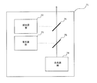
- FIG. 11 shows an example of a light source portion including light sources of red, blue, and green.
- the light source portion 71 includes a green light source part 72, a blue light source part 73, a red light source part 74, and dichroic mirrors 75 and 76.
- the green light source unit 72 has the configuration shown in FIG.
- Each of the red light source unit 74 and the blue light source unit 73 has the configuration shown in FIG.
- the solid light sources 11a, 11b, 12a, and 12b are configured by red LDs.
- the solid light sources 11a, 11b, 12a, and 12b are configured by blue LD.
- the dichroic mirror 75 has a reflection / transmission characteristic that reflects light in the blue wavelength region of the visible light wavelength region and transmits light in other wavelength regions.
- the dichroic mirror 76 has a reflection / transmission characteristic that reflects light in the green wavelength region of the visible light wavelength region and transmits light in other wavelength regions.
- the dichroic mirror 75 is disposed at a position where the optical axis of the red light source unit 74 and the optical axis of the blue light source unit 73 are orthogonal to each other. Red light emitted from the red light source unit 54 is incident on one surface of the dichroic mirror 75, and blue light emitted from the blue light source unit 73 is incident on the other surface of the dichroic mirror 75.
- the angle formed by the optical axis of the red light source 74 and one surface of the dichroic mirror 75 is 45 °, and the angle formed by the optical axis of the blue light source 73 and the other surface of the dichroic mirror 75 is 45 °.
- Red light from the red light source 74 passes through the dichroic mirror 75.
- Blue light from the blue light source unit 73 is reflected by the dichroic mirror 75 in the same direction as the transmitted green light. That is, the dichroic mirror 75 emits first composite light in which red light and blue light are mixed.
- the dichroic mirror 76 is disposed at a position where the optical axis of the red light source unit 54 and the optical axis of the green light source unit 72 are orthogonal to each other.
- the first composite light (blue / green) from the dichroic mirror 75 is incident on one surface of the dichroic mirror 76, and the green light emitted from the green light source unit 72 is incident on the other surface of the dichroic mirror 76.
- the angle formed by the optical axis of the red light source 74 and one surface of the dichroic mirror 76 is 45 °, and the angle formed by the optical axis of the green light source 72 and the other surface of the dichroic mirror 76 is 45 °.
- the first composite light from the dichroic mirror 75 passes through the dichroic mirror 76.
- the green light from the green light source 72 is reflected by the dichroic mirror 76 in the same direction as the transmitted first composite light. That is, the dichroic mirror 76 emits the second composite light (white light) obtained by mixing the first composite light (blue / red) and the green light.
- This second composite light (white light) is the output light of the light source portion 71.
- the light source portion 71 described above includes the light source portion including the first surface light source 50a and the first both-side telecentric lens 52a, the second surface light source 50b, and the second both-side telecentric lens of the light source device shown in FIG. 52b can be applied to each light source portion.
- the order in which the light beams from the green light source unit 72, the red light source unit 74, and the blue light source unit 73 are combined can be appropriately changed. For example, the green light from the green light source 72 and the blue light from the blue light source 73 are combined, and the first composite light obtained by mixing these green light and blue light and the red light from the red light source 74 are combined. You may do it.
- FIG. 12 is a schematic diagram showing a configuration of a light source device according to the second embodiment of the present invention.
- the light source device shown in FIG. 12 is different from the light source device of the first embodiment in that an optical element 157 is provided instead of the optical element 57.
- the first and second surface light sources 50a and 50b, the first optical system 51, and the second optical system 56 are basically the same as those in the first embodiment. Below, the structure of a light source device is demonstrated supposing illuminating a liquid crystal panel.
- the optical element 157 can be called an integrator.
- the optical element 157 is a fly-eye lens composed of a plurality of minute lenses, and includes a first fly-eye lens 157a and a second fly-eye lens 157b.
- the minute lenses of the first fly-eye lens 157a and the minute lenses of the second fly-eye lens 157b are arranged to face each other.
- the light beam incident on the first fly-eye lens 157a is divided into the number of minute lenses of the first fly-eye lens 157a.
- Each minute lens of the first fly-eye lens 157a has a similar shape to the effective display area of the liquid crystal panel and the area to which + ⁇ of the illumination area adjustment is added, and the light beam from the light source is transmitted to the second fly-eye lens.
- Each micro lens of the second fly-eye lens 157b forms an image of the corresponding micro lens of the first fly-eye lens 157a on the liquid crystal panel.
- the effective shape a shape composed of a plurality of microlenses
- the first fly's eye lens 157a is irradiated with a light beam may or may not be similar to the shape of each microlens.
- the first optical system 51 forms the light source images of the first and second surface light sources 50a and 50b in different regions on the first image formation surface 55.
- the first optical system 51 includes a reflecting element 53, a first both-side telecentric optical system 52a, and a second both-side telecentric optical system 52b.
- the reflective element 53 includes first and second reflective surfaces 53a and 53b provided so as to be perpendicular to each other.
- the first both-side telecentric optical system 52a is provided on the optical path between the first surface light source 50a and the first reflection surface 53a, and the light source image of the first surface light source 50a is displayed on the first reflection surface.
- An image is formed on the first image plane 55 via 53a.
- the second both-side telecentric optical system 52b is provided on the optical path between the second surface light source 50b and the second reflection surface 53b, and the light source image of the second surface light source 50b is used as the second reflection surface.
- An image is formed on the first image plane 55 via 53b.
- the first both-side telecentric optical system 52 a and the second both-side telecentric optical system 52 b have the same structure, and are arranged so that their emission surfaces face each other with the reflective element 53 interposed therebetween.
- the principal ray (optical axis) of the first light beam from the first both-side telecentric optical system 52a and the principal ray (optical axis) of the second light beam from the second both-side telecentric optical system 52b are on the same axis. I'm doing it.
- the virtual imaging plane 54 indicates an imaging plane in the state where the first and second reflecting surfaces 53a and 53b are not interposed in the first both-side telecentric optical system 52a and the second both-side telecentric optical system 52b, respectively.
- the virtual imaging plane 54 and the first imaging plane 55 are orthogonal to each other.
- the angle formed between the first reflecting surface 53a and the virtual imaging surface 54 is 45 °, and the angle formed between the principal ray of the light beam from the first both-side telecentric optical system 52a and the first reflecting surface 53a is 45 °. It is.
- the angle formed between the second reflecting surface 53b and the virtual imaging surface 54 is 45 °, and the angle formed between the principal ray of the light beam from the second both-side telecentric optical system 52b and the second reflecting surface 53b. Is also 45 °.
- the first reflecting surface 53a and the second reflecting surface 53b reflect the first light beam from the first both-side telecentric optical system 52a and the second light beam from the second both-side telecentric optical system 52b in the same direction. .
- the principal ray of the first light beam from the first both-side telecentric optical system 52a and the principal ray of the second light beam from the second both-side telecentric optical system 52b are located on the same axis.
- the apex angle portion which is the junction of the first and second reflecting surfaces 53a, 53b, is You may arrange
- the second optical system 56 and the first fly-eye lens 57a convert the combined surface light source composed of the light source images of the first and second surface light sources formed on the first image forming surface 55 into the second fly. An image is formed in the vicinity of the eye lens 57b.
- the second optical system 56 may include a third double-sided telecentric lens optical system.
- the light source image 58a is a light source image of the first surface light source 50a
- the light source image 58b is a light source image of the second surface light source 50b.
- the light source images 58a and 58b have a line-symmetric shape.
- the light source images 58a and 58b are formed at an interval d.
- the combined surface light source 58 includes light source images 58a and 58b.
- the reflecting element 53 can be configured by a V-shaped mirror or a right-angle prism.
- the V-shaped mirror shown in FIG. 3 can be used as the reflective element 53.
- the V-shaped mirror is composed of two reflecting portions 60a and 60b provided so that the reflecting surfaces thereof are perpendicular to each other.
- Each of the reflecting portions 60a and 60b has a reflecting surface formed on the surface opposite to the virtual imaging surface 54 side.
- the reflecting surface and the virtual imaging surface 54 (or the first imaging surface 55) The angle formed is 45 °.
- the interval between the images 58a and 58b is also widened.
- the composite surface is considered in consideration of the conditions (1) to (4) in the case where the reflecting element 53 is moved in the direction perpendicular to the first image plane 55 described in the first embodiment.
- the first both-side telecentric optical system 52a, the second both-side telecentric optical system 52b, and the reflecting element 53 are arranged so that the light source 58 has a predetermined shape that can improve the light utilization efficiency in the optical system after the optical element 57. Be placed.
- the reflective element 53 is arranged so that vignetting occurs in the first and second light beams at the apex angles of the reflecting portions 60a and 60b.
- the combined surface light source 58 shown in FIG. 5 is formed on the first imaging surface 55.
- the distance D between the light source images 58a and 58b it is possible to minimize the degradation of light utilization efficiency due to etendue restrictions, and as a result, it is possible to achieve high brightness.
- Equation 1 The F value (F number) of the projection lens is given by Equation 1 described above.
- ⁇ is a light beam spread angle (half value).
- F / 1.7 the F value of the projection lens is mainly about 1.7.
- Etendue is given by Equation 2 above.
- A is the area (effective display area) of the liquid crystal panel, and ⁇ is a half angle of the F value of the projection lens.
- vignetting is generated as shown in FIG. 5 in order to minimize degradation of light utilization efficiency.
- This etendue value of 67.5 is close to the etendue value of 50.4.
- the right-angle prism shown in FIG. 6 can be used in this embodiment.
- the right-angle prism 61 has reflection surfaces 61a and 61b that are perpendicular to each other.
- the angle formed by the reflecting surface 61a and the virtual imaging surface 54 (or the first imaging surface 55) is 45 °.
- the angle formed by the reflecting surface 61b and the virtual imaging surface 54 (or the first imaging surface 55) is also 45 °.
- the light source images 58a and 58b change as shown in FIG.
- the interval between the images 58a and 58b is also widened.
- 61 is arranged. Specifically, the right-angle prism 61 is arranged so that vignetting occurs in the first and second light beams at the apex angles of the reflecting surfaces 61a and 61b. Even when the right-angle prism 61 is used, the same effect as that obtained when the V-shaped mirror is used is obtained.
- the apex angle portion of the right-angle prism 61 is a right-angle surface
- the apex angle portion of the V-shaped mirror is a right-angle surface. It is not.
- the apex angle portion of the right-angle prism 61 is the height d1 and the junction portion of the reflection portions 60a and 60b of the V-shaped mirror. It is located on the first image plane 55 side.
- the light source images 58a and 58b (broken line) when the right-angle prism 61 is used are larger than the light source images 58a and 58b (solid line) when the V-shaped mirror is used.
- the size of the combined surface light source 58 does not change between the case where the right-angle prism 61 is used and the case where the V-shaped mirror is used, the light source images 58a and 58b (solid lines) become larger, so that light can be captured more efficiently. Light utilization efficiency can be further improved.
- the first and second surface light sources 50a and 50b and the first and second both-side telecentric optical systems 52a and 52b will be specifically described.
- the first light source part composed of the first surface light source 50a and the first both-side telecentric optical system 52a, and the second light source part composed of the second surface light source 50b and the twelfth both-side telecentric optical system 52b They have the same structure.
- Solid-state light sources can be used as the first and second surface light sources 50a and 50b.
- the structure of the light source part shown in FIG. 9 can be used for the solid light source.
- the light source portion includes light source units 1a and 1b, condenser lenses 2a and 2b, reflection mirrors 3a, 3b, 4a and 4b, a diffuser plate 5, a light pipe 6 and lenses 7 to 9.
- the light source unit 1a includes solid light sources 11a and 12a that emit light of the same color and a reflection mirror 13a.
- the solid light sources 11a and 12a have the same structure, and include, for example, a plurality of laser diodes (LDs) that output laser light having a center wavelength in a wavelength region of a predetermined color.
- LDs laser diodes
- the reflection mirror 13a is a mirror having a stripe structure in which reflection areas and transmission areas are alternately arranged.
- a stripe-shaped mirror can be formed by vapor-depositing a band-shaped reflective region on a transparent substrate at a predetermined interval.
- Each row of LDs of the solid-state light source 11a and each transmission region of the reflection mirror 13a have a one-to-one correspondence, and the laser light emitted from the LD of each row passes through the corresponding transmission region of the reflection mirror 13a.
- Each row of LDs of the solid-state light source 12a and each reflection region of the reflection mirror 13a have a one-to-one correspondence.
- the reflected laser beam is reflected in the same direction as the traveling direction.
- the laser light transmitted through the transmission region and the laser light reflected by the reflection region are output light of the light source unit 1a, and this output light is incident on the condenser lens 2a.
- the light source unit 1b outputs light of the same color as the light source unit 1a, and includes solid light sources 11b and 12b and a reflection mirror 13b.
- the portion composed of the solid light sources 11b and 12b and the reflection mirror 13b has the same structure as the portion composed of the solid light sources 11a and 12a and the reflection mirror 13a.
- the laser light emitted from the solid light source 11b is transmitted through each transmission region of the reflection mirror 13b, and the laser light emitted from the solid light source 12b is the same as the traveling direction of the laser light transmitted through the transmission region in each reflection region of the reflection mirror 13b. Reflected in the direction.
- the laser light transmitted through the transmission region and the laser light reflected by the reflection region are output light of the light source unit 1b, and this output light is incident on the condenser lens 2b.
- the laser light that has passed through the condenser lens 2 a passes through the reflecting mirrors 3 a and 4 a and the diffusion plate 5 in order and enters the incident surface of the light pipe 6.
- the laser light that has passed through the condenser lens 2 b passes through the reflecting mirrors 3 b and 4 b and the diffusion plate 5 in order and enters the incident surface of the light pipe 6.
- Each of the light source units 1a and 1b can be called a light source unit.
- the condensing lenses 2a and 2b and the reflecting mirrors 3a, 3b, 4a and 4b can be called light folding means.
- the length of the first optical path from the light source unit 1 a to the incident surface of the light pipe 6 is the same as the length of the second optical path from the light source unit 1 b to the incident surface of the light pipe 6.
- the condensing angle of the condensing lens 2a (the angle given by 2 ⁇ when the angle between the optical axis and the outermost light beam of the light beam is ⁇ ) is the same as that of the condensing lens 2b.
- the incident angle of the central ray of the light beam incident on the incident surface of the light pipe 6 in the first optical path is the same as the incident angle of the central beam of the light beam incident on the incident surface of the light pipe 6 in the second optical path.
- the light pipe 6 is composed of a columnar light guide, and one of both end faces of the light guide is an entrance surface, and the other is an exit surface.
- the light enters the entrance surface, and light propagates through the light guide and exits.
- An optical element (light uniformizing element) emitted from the surface.
- the light is reflected a plurality of times inside the light guide so that a uniform surface light source can be formed on the exit surface.
- the condensing lens 2 a condenses the laser light from the light source unit 1 a and makes it incident on the incident surface of the light pipe 6.
- the condensing lens 2 b condenses the laser light from the light source unit 1 b and makes it incident on the incident surface of the light pipe 6. You may comprise so that the condensing position of each condensing lens 2a, 2b on the entrance plane of the light pipe 6 may become the same.
- the lenses 7 to 9 constitute a bilateral telecentric lens.
- This double-sided telecentric lens is the first double-sided telecentric lens 52a or the second double-sided telecentric lens 52b shown in FIG.
- the space around the light pipe 6 is utilized, and the light source units 1a and 1b are arranged in the space, so that the apparatus can be miniaturized.
- the laser light emitted from each of the light source units 1 a and 1 b is folded back and incident on the incident surface of the light pipe 6. In this way, the apparatus can be miniaturized by folding the optical path.
- the configuration of the light source portion described above is the same as that of the light source device shown in FIG. 12, the light source portion including the first surface light source 50 a and the first both-side telecentric lens 52 a, the second surface light source 50 b and the second both-side telecentric.
- the present invention can be applied to the light source portion composed of the lens 52b.
- the exit surface (opening surface) of the light pipe 6 constitutes a surface light emitting portion, and a light source image of this surface light emitting portion is formed on the first image forming surface 55 as a light source image 58a or 58b.
- Each of the first and second surface light sources 50a and 50b may be a phosphor light source using a phosphor.
- the phosphor light source may include an excitation light source that emits excitation light and a fluorescent unit that includes a phosphor that is excited by the excitation light and emits fluorescence. In this case, the phosphor may emit green fluorescence.
- the light source part provided with the phosphor light source shown in FIG. 10 can be used.
- the light source portion includes light source units 21a and 21b, condenser lenses 22a and 22b, reflection mirrors 23a, 23b, 24a, 24b and 34, a diffuser plate 25, a light pipe 26, lenses 27 to 32, A dichroic mirror 33 and a fluorescent wheel 35 are provided.
- the light source units 21a and 21b are excitation light sources for exciting the phosphor, and emit excitation light of the same color.
- the light source unit 21a includes solid light sources 211a and 212a that emit excitation light of the same color and a reflection mirror 213a.
- the solid light sources 211a and 212a have the same structure, and include, for example, a plurality of laser diodes (LDs) that output blue laser light having a center wavelength in a blue wavelength region.
- LDs laser diodes
- (n (rows) ⁇ m (columns)) of blue LDs formed on a holding member provided with a heat radiating portion is used.
- the reflection mirror 213a is a mirror having a stripe structure in which reflection areas and transmission areas are alternately arranged.
- a stripe-shaped mirror can be formed by vapor-depositing a band-shaped reflective region on a transparent substrate at a predetermined interval.
- Each row of blue LDs of the solid-state light source 211a and each transmission region of the reflection mirror 213a have a one-to-one correspondence, and the blue laser light emitted from the blue LD of each row passes through the corresponding transmission region of the reflection mirror 213a. pass.
- Each row of blue LDs of the solid-state light source 212a and each reflection region of the reflection mirror 213a have a one-to-one correspondence, and the blue laser light emitted from the blue LD of each row is reflected by the corresponding reflection region of the reflection mirror 213a.
- the blue laser light that has passed through the transmission region is reflected in the same direction as the traveling direction.
- the blue laser light transmitted through the transmission region and the blue laser light reflected by the reflection region are output light of the light source unit 21a, and this output light is incident on the condenser lens 22a.
- the light source unit 21b includes solid light sources 211b and 212b and a reflection mirror 213b.
- the portion composed of the solid light sources 211b and 212b and the reflection mirror 213b has the same structure as the portion composed of the solid light sources 211a and 212a and the reflection mirror 213a.
- the blue laser light emitted from the solid light source 211b is transmitted through each transmission region of the reflection mirror 213b, and the blue laser light emitted from the solid light source 212b is transmitted through the transmission region in each reflection region of the reflection mirror 213b. Reflected in the same direction as the direction.
- the blue laser light transmitted through the transmission region and the blue laser light reflected by the reflection region are output light of the light source unit 21b, and this output light is incident on the condenser lens 22b.
- the blue laser light that has passed through the condenser lens 22 a passes through the reflecting mirrors 23 a and 24 a and the diffusion plate 25 in order, and enters the incident surface of the light pipe 26.
- the blue laser light that has passed through the condenser lens 22b sequentially passes through the reflection mirrors 23b and 24b and the diffusion plate 25 and enters the incident surface of the light pipe 26.
- the length of the first optical path from the light source unit 21a to the incident surface of the light pipe 26 is the same as the length of the second optical path from the light source unit 21b to the incident surface of the light pipe 26.
- the condensing angle of the condensing lens 22a is the same as that of the condensing lens 22b.
- the incident angle of the central ray of the light beam incident on the incident surface of the light pipe 26 in the first optical path is the same as the incident angle of the central ray of the light beam incident on the incident surface of the light pipe 26 in the second optical path.
- the light pipe 26 is composed of a columnar light guide, and one of both end faces of the light guide is an entrance surface, and the other is an exit surface. Light is incident from the entrance surface and emitted through the light guide. An optical element (light uniformizing element) emitted from the surface. The light is reflected a plurality of times inside the light guide so that a uniform surface light source can be formed on the exit surface.
- a light tunnel having a hollow interior and an inner surface made of a mirror, a rod having a polygonal column made of a transparent material such as glass, or the like can be used.
- the condensing lens 22 a condenses the laser light from the light source unit 21 a and makes it incident on the incident surface of the light pipe 26.
- the condensing lens 22 b condenses the laser light from the light source unit 21 b and makes it incident on the incident surface of the light pipe 26. You may comprise so that the condensing position of each condensing lens 22a, 22b on the entrance plane of the light pipe 26 may become the same.
- the lenses 27 and 28 and the dichroic mirror 33 are arranged in this order in the traveling direction of the blue laser light (blue excitation light) emitted from the emission surface of the light pipe 26.
- the lenses 27 and 28 are condensing lenses.
- the dichroic mirror 33 has a reflection / transmission characteristic that reflects light in the blue wavelength region of the visible light wavelength region and transmits light in other wavelength regions.
- the blue laser light from the light pipe 26 is reflected by the dichroic mirror 33 after passing through the lenses 27 and 28.
- the lenses 29 to 31 and the fluorescent wheel 35 are arranged in this order.
- the lenses 29 to 31 are condensing lenses.
- the fluorescent wheel 35 includes a rotatable circular substrate and a phosphor portion formed along the circumferential direction on the circular substrate.
- the central portion of the circular substrate is supported by the output shaft of the rotary motor, and the rotary motor rotates the circular substrate.
- the phosphor part includes a phosphor that can be excited by blue laser light from the dichroic mirror 33.
- a yellow phosphor that emits yellow fluorescence, a green phosphor that emits green fluorescence, or the like can be used.
- a green phosphor is used.
- the blue laser light from the dichroic mirror 33 passes through the lenses 29 to 31 and then enters the phosphor portion of the fluorescent wheel 35.
- Green fluorescent light (diverging light) emitted from the phosphor part passes through the lenses 29-30.
- the green fluorescence that has passed through the lenses 29 to 30 passes through the dichroic mirror 33.
- the lens 32 and the reflection mirror 34 are arranged in this order in the traveling direction of the green fluorescence (transmitted light) from the dichroic mirror 33.
- the lens 32 is a condenser lens.
- the lenses 27 to 32 collect the blue laser light emitted from the emission surface of the light pipe 26 on the phosphor part of the fluorescent wheel 35. Further, the lenses 29 to 32 act so as to collect the green fluorescence (diverged light) emitted from the phosphor portion. The green fluorescence that has passed through the lens 32 is reflected by the reflection mirror 34. The reflected light (green fluorescence) from the reflection mirror 34 is the output of the light source portion.
- a lens for obtaining a parallel light beam may be disposed in the optical path of green fluorescence that has passed through the lens 32.
- the lenses 27, 28, and 32 and at least one lens provided in the optical path that has passed through the lens 32 constitute a double-sided telecentric lens. This double-sided telecentric lens is the first double-sided telecentric lens 52a or the second double-sided telecentric lens 52b shown in FIG.
- the configuration of the light source portion described above is the same as that of the light source device shown in FIG. 12, the light source portion including the first surface light source 50 a and the first both-side telecentric lens 52 a, the second surface light source 50 b and the second both-side telecentric.
- the present invention can be applied to the light source portion composed of the lens 52b.
- the shape of the exit surface (opening surface) of the light pipe 26 is projected onto the phosphor surface of the fluorescent wheel 35.
- the shape of the spot of blue laser light (excitation light) on the phosphor surface is similar to the shape of the exit surface (opening surface) of the light pipe 26.
- a light source image of a spot on the phosphor surface is imaged on the first imaging surface 55 as a light source image 58a or a light source image 58b.
- the first and second surface light sources 50a and 50b and the first and second both-side telecentric optical systems 52a and 52b may have the following configurations.
- Each of the first and second surface light sources 50a and 50b may include a plurality of light source units having different emission colors, and the first and second both-side telecentric optical systems 52a and 52b may be provided for each emission color.
- the first optical system 51 includes a first color combining unit that combines a plurality of light beams emitted from the plurality of light source units of the first surface light source 50a and emits the same light path, and a second color combining unit.
- a second color synthesis unit that synthesizes a plurality of light beams emitted from the plurality of light source units of the surface light source 50b and emits the light beams through the same optical path.
- the light source portion 71 includes a green light source unit 72, a blue light source unit 73, a red light source unit 74, and dichroic mirrors 75 and 76.
- the green light source unit 72 has the configuration shown in FIG.
- Each of the red light source unit 74 and the blue light source unit 73 has the configuration shown in FIG.
- the solid light sources 11a, 11b, 12a, and 12b are configured by red LDs.
- the solid light sources 11a, 11b, 12a, and 12b are configured by blue LD.
- the dichroic mirror 75 has a reflection / transmission characteristic that reflects light in the blue wavelength region of the visible light wavelength region and transmits light in other wavelength regions.
- the dichroic mirror 76 has a reflection / transmission characteristic that reflects light in the green wavelength region of the visible light wavelength region and transmits light in other wavelength regions.
- the dichroic mirror 75 is disposed at a position where the optical axis of the red light source unit 74 and the optical axis of the blue light source unit 73 are orthogonal to each other. Red light emitted from the red light source unit 54 is incident on one surface of the dichroic mirror 75, and blue light emitted from the blue light source unit 73 is incident on the other surface of the dichroic mirror 75.
- the angle formed by the optical axis of the red light source 74 and one surface of the dichroic mirror 75 is 45 °, and the angle formed by the optical axis of the blue light source 73 and the other surface of the dichroic mirror 75 is 45 °.
- Red light from the red light source 74 passes through the dichroic mirror 75.
- Blue light from the blue light source unit 73 is reflected by the dichroic mirror 75 in the same direction as the transmitted green light. That is, the dichroic mirror 75 emits first composite light in which red light and blue light are mixed.
- the dichroic mirror 76 is disposed at a position where the optical axis of the red light source unit 54 and the optical axis of the green light source unit 72 are orthogonal to each other.
- the first composite light (blue / green) from the dichroic mirror 75 is incident on one surface of the dichroic mirror 76, and the green light emitted from the green light source unit 72 is incident on the other surface of the dichroic mirror 76.
- the angle formed by the optical axis of the red light source 74 and one surface of the dichroic mirror 76 is 45 °, and the angle formed by the optical axis of the green light source 72 and the other surface of the dichroic mirror 76 is 45 °.
- the first composite light from the dichroic mirror 75 passes through the dichroic mirror 76.
- the green light from the green light source 72 is reflected by the dichroic mirror 76 in the same direction as the transmitted first composite light. That is, the dichroic mirror 76 emits the second composite light (white light) obtained by mixing the first composite light (blue / red) and the green light.
- This second composite light (white light) is the output light of the light source portion 71.
- the light source portion 71 described above includes the light source portion including the first surface light source 50a and the first both-side telecentric lens 52a, the second surface light source 50b, and the second both-side telecentric lens of the light source device shown in FIG. 52b can be applied to each light source portion.
- the order in which the light beams from the green light source unit 72, the red light source unit 74, and the blue light source unit 73 are combined can be appropriately changed. For example, the green light from the green light source 72 and the blue light from the blue light source 73 are combined, and the first composite light obtained by mixing these green light and blue light and the red light from the red light source 74 are combined. You may do it.
- the diffuser plate currently used by each of the red light source part 74 and the blue light source part 73 can also be shared.
- a diffuser plate common to the red light source unit 74 and the blue light source unit 73 may be provided on the optical path between the dichroic mirror 75 and the dichroic mirror 76.
- the diffusion plate may be vibrated to suppress speckle.
- the light source device of the present embodiment includes first and second light sources and a first optical system that forms light source images of the first and second light sources in different regions on the same imaging plane.
- the first optical system has a first reflecting surface that reflects the first light beam from the first light source toward the imaging surface, and a second light beam from the second light source toward the imaging surface. And a second reflecting surface for reflecting.
- the apex angle portion which is the junction of the first and second reflecting surfaces, is incident on the first reflecting surface.
- the first light source and the second light source may be configured using, for example, the first surface light source 50a and the first surface light source 50a shown in FIG.
- the reflective element constituting the first optical system may be configured using the reflective element 53 shown in FIG. 1 or FIG.
- the first and second reflection surfaces are the first reflection surface 53a and the second reflection surface 53b.
- the apex angle portion which is a joint portion of the first and second reflecting surfaces 53a, 53b, is the first And it arrange
- the light source device of the present embodiment includes first and second light sources and a first optical system that forms light source images of the first and second light sources in different regions on the same imaging plane.
- the first optical system has a first reflecting surface that reflects the first light beam from the first light source toward the imaging surface, and a second light beam from the second light source toward the imaging surface.
- a second reflecting surface that reflects, a part of the first light beam is not reflected by the first reflecting surface, and a part of the second light beam is the second reflecting surface. It is comprised so that it may not be reflected by.
- the first light source and the second light source may be configured using, for example, the first surface light source 50a and the first surface light source 50a shown in FIG.
- the reflective element constituting the first optical system may be configured using the reflective element 53 shown in FIG. 1 or FIG.
- the first and second reflection surfaces are the first reflection surface 53a and the second reflection surface 53b.
- a part of the first light flux from the first surface light source 50a is not reflected by the first reflecting surface 53a.
- a part of the second light flux from the second surface light source 50b is not reflected by the second reflecting surface 53b.
- a second optical system into which a light beam from a combined light source composed of light source images of the first and second light sources formed on the imaging surface is incident;
- An integrator that includes an incident surface on which a light beam from the second optical system is incident and that forms a uniform surface light source may be further included.
- the second optical system may be configured to form a light source image of the combined light source on the incident surface.
- the integrator includes at least one of a fly-eye lens, a rod, and a light tunnel.
- the projection display device includes a light source device according to any of the first to fourth embodiments described above, a display element that modulates light output from the light source device to form an image, and the display element.
- the display element a liquid crystal display panel or DMD can be used.
- FIG. 13 schematically shows the configuration of the first projection display device.
- the first projection display device is a three-plate projector, and includes a light source device 601 including a light source portion 71 to which the light source device of the first embodiment is applied. In FIG. 13, for convenience, each part of the light source device 601 is not shown.
- White light emitted from the optical element 57 of the light source device 601 enters a TIR (Total Internal Reflection) prism 605 via lenses 602 and 603 and a reflection mirror 604.
- the optical element 57 there can be used a light tunnel having a hollow interior and an inner surface made of a mirror, a rod having a polygonal column formed of a transparent material such as glass, and the like.
- the TIR prism 605 is a total reflection prism assembly having a total reflection surface therein, and includes two triangular prisms.
- One triangular prism is a right-angle prism, and has first and second surfaces that form a right-angle side and a third surface that forms an oblique side.
- the other triangular prism has first to third surfaces constituting each line segment of the triangle.
- the third surface of the right-angle prism is disposed so as to face the first surface of the other triangular prism.
- the first surface of the right-angle prism is the incident surface of the TIR prism 605.
- the color prism 606 is disposed so as to face the second surface of the right-angle prism.
- the second surface of the other triangular prism is the exit surface of the TIR prism 605 and is parallel to the second surface of the right-angle prism.
- a projection lens 610 is disposed on the exit surface side.
- Light (white light) from the reflection mirror 604 enters the incident surface of the TIR prism 605.
- the light incident on the TIR prism 605 is totally reflected by the internal total reflection surface and is emitted from the second surface of the right-angle prism.
- the light emitted from the second surface enters the color prism 606.
- the color prism 606 includes a plurality of prisms and has first to fourth surfaces.
- the first surface faces the second surface of the right-angle prism of the TIR prism 605.
- the red display panel 608 is disposed to face the second surface
- the green display panel 607 is disposed to face the third surface
- the blue display panel 609 is opposed to the fourth surface.
- red light is emitted from the second surface
- green light is emitted from the third surface
- blue light is emitted from the fourth surface.
- a DMD digital mirror device
- liquid crystal display panel may be used as the display panels 607 to 609.
- Each of the display panels 607 to 609 has an image forming area composed of a plurality of micromirrors arranged in a matrix.
- the micromirror is configured such that the angle changes according to the drive voltage, and the reflection angle differs between when the drive voltage indicating the on state is supplied and when the drive voltage indicating the off state is supplied.
- Red light emitted from the second surface enters the red display panel 608.
- the red display panel 608 spatially modulates the incident red light to form a red image.
- Red image light is incident on the second surface of the color prism 606 from the red display panel 608.
- the red image light incident from the second surface is emitted from the first surface.
- the red image light emitted from the first surface is incident on the second surface of the right-angle prism of the TIR prism 605.
- the green light emitted from the third surface enters the green display panel 607.
- the green display panel 607 spatially modulates the incident green light to form a green image.
- Green image light is incident on the third surface of the color prism 606 from the green display panel 607.
- the green image light incident from the third surface is emitted from the first surface.
- the green image light emitted from the first surface is incident on the second surface of the right-angle prism of the TIR prism 605.
- the blue light emitted from the fourth surface enters the blue display panel 609.
- the blue display panel 609 spatially modulates incident blue light to form a blue image.
- Blue image light enters the fourth surface of the color prism 606 from the blue display panel 609.
- the blue image light incident from the fourth surface is emitted from the first surface.
- the blue image light emitted from the first surface is incident on the second surface of the right-angle prism of the TIR prism 605.
- the red image light, the green image light, and the blue image light incident from the second surface of the right-angle prism are emitted toward the projection lens 610 from the emission surface.
- the projection lens 610 projects the red image, the green image, and the blue image formed on the red display panel 608, the green display panel 607, and the blue display panel 609, respectively, onto the screen.
- the projection lens 610 is an enlarged projection optical system composed of a plurality of lenses.
- a first light source portion including a first surface light source 50a and a first both-side telecentric optical system 52a
- a second light source portion including a second surface light source 50b and a twelfth both-side telecentric optical system 52b.
- the light source portions have the same structure. Thereby, in the illumination light that illuminates the DMD, it is possible to suppress color unevenness caused by different in-plane distributions of red, blue, and green.
- the shape and size of the spot on the phosphor surface are determined by the intensity (light density) of excitation light on the phosphor, the capture angle of the light beam emitted from the phosphor, the incident angle of the light beam on the optical element 57, the optical element
- the design is appropriately made based on the aspect ratio of the incident surface 57, the configuration of the optical system in the optical path from the phosphor to the optical element 57, and the like.
- the reflection surface inside the light guide portion 57a constituting the optical element 57 is tapered, the area of the surface light source is slightly increased, but the divergence angle of light emitted from the emission surface can be reduced. As a result, the loss of incident light with respect to the optical component having a predetermined size can be reduced.
- FIG. 14 schematically shows the configuration of the second projection display device.
- the second projection display device is a three-plate projector, and includes a light source device 501 including a light source portion 71 to which the light source device of the second embodiment is applied. In FIG. 14, for convenience, each part of the light source device 501 is not shown.
- White light emitted from the light source device 501 enters the polarization conversion element 502 via the first fly-eye lens 57a and the second fly-eye lens 57b.
- the polarization conversion element 502 is disposed in the vicinity of the second fly-eye lens 57b.
- FIG. 15 shows the configuration of the polarization conversion element 502. As shown in FIG.
- the polarization conversion element 502 includes a polarization separation film 502a that reflects P-polarized light and transmits S-polarized light, and a half-wave plate 502b.
- white light random polarization
- the polarization separation film 502a separates random polarized light into P-polarized light and S-polarized linearly polarized light.
- the P-polarized light that has passed through the polarization separation film 502a passes through the half-wave plate 502b.
- the half-wave plate 502b rotates the polarization direction of the incident P-polarized light by 90 degrees and emits it as S-polarized light.
- the S-polarized light reflected by the polarization separation film 502a is reflected again by the adjacent polarization separation film 502a and emitted while maintaining the polarization. In this way, the polarization direction is aligned in a single direction.
- the dichroic mirror 504 has a characteristic of reflecting light in the red wavelength region of visible light and transmitting light in other wavelength regions. Of the light emitted from the polarization conversion element 502, red light is reflected by the dichroic mirror 504. The reflected light (red) of the dichroic mirror 504 is incident on the liquid crystal panel 507 via the field lens 505, the reflecting mirror 506, and the polarizing plate 517. Light transmitted through the dichroic mirror 504 (green and blue) enters the dichroic mirror 509.
- the dichroic mirror 509 has a characteristic of reflecting light in the green wavelength region of visible light and transmitting light in other wavelength regions. Green light out of the light emitted from the polarization conversion element 502 is reflected by the dichroic mirror 509 after passing through the dichroic mirror 504. Reflected light (green) of the dichroic mirror 509 is incident on the liquid crystal panel 510 via the polarizing plate 518. Blue light out of the light emitted from the polarization conversion element 502 is transmitted through the dichroic mirrors 504 and 509, respectively.
- the transmitted light (blue) of the dichroic mirror 509 is incident on the liquid crystal panel 516 through the relay lens 511, the reflection mirror 512, the relay lens 513, the reflection mirror 514, the relay lens 515, and the polarizing plate 519.
- the superimposing lens 503 and the field lenses 505 and 508 direct chief rays from the microlenses of the first fly-eye lens 57a toward the center of the liquid crystal panels 507 and 510, and images the microlenses on the liquid crystal panels 507 and 510. Overlapping with. Between the dichroic mirror 509 and the relay lens 511, a rectangular uniform illumination image is formed by superimposing the images of the minute lenses of the first fly-eye lens 57a.
- a relay optical system including the relay lens 511, the reflection mirror 512, the relay lens 513, the reflection mirror 514, and the relay lens 515 is an equal-magnification image of a rectangular uniform illumination image formed between the dichroic mirror 509 and the relay lens 511.
- a polarizing plate 517 and a polarizing plate 520 are respectively disposed on the incident surface side and the emission surface side of the liquid crystal panel 507. Using these polarizing plates 517 and 520, gradation characteristics corresponding to the spatial modulation of the liquid crystal panel 507 are obtained.
- a polarizing plate 518 and a polarizing plate 521 are disposed on the incident surface side and the emitting surface side of the liquid crystal panel 510, respectively, and a polarizing plate 519 and a polarizing plate 522 are disposed on the incident surface side and the emitting surface side of the liquid crystal panel 516, respectively.
- the cross dichroic prism 523 has first to third entrance surfaces and an exit surface.
- the liquid crystal panel 507 is disposed to face the first incident surface of the cross dichroic prism 523.
- the liquid crystal panel 510 is disposed to face the second incident surface of the cross dichroic prism 523.
- the liquid crystal panel 516 is disposed to face the third incident surface of the cross dichroic prism 523.
- the liquid crystal panels 507, 510, and 516 spatially modulate incident light.
- Light emitted from the liquid crystal panel 507 (red) is incident on the first incident surface of the cross dichroic prism 523 via the polarizing plate 520.
- Light emitted from the liquid crystal panel 510 (green) is incident on the second incident surface of the cross dichroic prism 523 via the polarizing plate 521.
- Light emitted from the liquid crystal panel 516 blue enters the third incident surface of the cross dichroic prism 523 via the polarizing plate 522.
- the red light incident from the first incident surface, the green light incident from the second incident surface, and the blue light incident from the third incident surface overlap each other and exit from the exit surface.
- the cross dichroic prism 523 synthesizes and emits red image light, green image light, and blue image light from the liquid crystal panels 507, 510, and 516 in the same optical path.
- the projection lens 530 is disposed to face the exit surface of the cross dichroic prism 523. Red image light, green image light, and blue image light emitted from the liquid crystal panels 507, 510, and 516 are incident on the projection lens 530 through the same optical path.
- the projection lens 530 enlarges and projects images formed by the liquid crystal panels 507, 510, and 516, respectively.
- a reflective element comprising: 2 reflective surfaces; When viewed from a direction perpendicular to a plane orthogonal to the first and second reflecting surfaces, an apex angle portion that is a joint portion of the first and second reflecting surfaces is incident on the first reflecting surface.
- the light source device is disposed inside the outermost peripheral portion of the first light flux and the second light flux incident on the second reflecting surface.
- a first optical system that images the light source images of the first and second light sources in different regions on the same imaging plane,
- the first optical system includes: A first reflecting surface that reflects the first light beam from the first light source toward the imaging surface, and a second reflecting surface that reflects the second light beam from the second light source toward the imaging surface.
- a reflective element comprising: 2 reflective surfaces; Part of the first light flux is not reflected by the first reflecting surface, A part of said 2nd light beam is a light source device which is not reflected by the said 2nd reflective surface.
- the second optical system is a light source device that forms a light source image of the combined light source on the incident surface.
- the integrator is a light source device that is a columnar light guide.
- the integrator has first and second lenses; The second optical system and the first lens form a light source image of the combined light source on the second lens and the vicinity thereof.
- the first optical system includes: An optical system of a first light source that guides a light beam from the first light source to the first reflecting surface; An optical system of a second light source that guides a light beam from the second light source to the second reflecting surface; The optical axis on the exit side of the optical system of the first light source and the optical axis on the exit side of the optical system of the second light source are the same axis, The light source device, wherein the first and second reflecting surfaces form a right angle.
- the optical system of the first and second light sources is a light source device in which both are telecentric optical systems.
- the light reflecting device is a light source device, wherein the reflective element is formed of a prism having first and second surfaces that are perpendicular to each other, and the first and second surfaces constitute the first and second reflective surfaces, respectively.
- Each of the first and second light sources is An excitation light source that emits excitation light; And a fluorescent part including a phosphor that emits fluorescence when excited by the excitation light.
- Appendix 12 In the light source device according to attachment 11, The light source device, wherein the phosphor emits green fluorescence.
- the first optical system includes: A first color synthesis unit that synthesizes a plurality of light beams emitted from the plurality of light source units of the first light source and emits the same light path; And a second color synthesis unit that synthesizes a plurality of light beams emitted from the plurality of light source units of the second light source and emits them through the same optical path.
- the plurality of light source units include a red light source unit that emits red light, a blue light source unit that emits blue light, and a green light source unit that emits green light.
- the red light source unit and the blue light source unit are solid light sources,
- the green light source unit is An excitation light source that emits excitation light;
- a fluorescent part that includes a phosphor that emits green fluorescence when excited by the excitation light.
- Appendix 16 The light source device according to any one of appendices 1 to 15, A display element that modulates the light output from the light source device to form an image; A projection display device, comprising: a projection lens that projects an image formed by the display element.
- An illumination method using first and second light sources The first light flux from the first light source is reflected by the first reflecting surface of the reflecting element toward the imaging surface, A second light flux from the second light source is reflected by the second reflecting surface of the reflecting element toward the imaging surface; Forming light source images of the first and second light sources in different regions on the imaging plane; When viewed from a direction perpendicular to a plane orthogonal to the first and second reflecting surfaces, an apex angle portion that is a joint portion of the first and second reflecting surfaces is incident on the first reflecting surface.
- An illumination method wherein the first light flux and the second light flux incident on the second reflecting surface are arranged on the inner side of the outermost peripheral portion.
- Appendix 18 The lighting method according to appendix 17, A light beam from a combined light source composed of light source images of the first and second light sources formed on the imaging surface is incident on the integrator, Modulating the light from the integrator to form an image, A display method for projecting the formed image.
Landscapes
- Physics & Mathematics (AREA)
- General Physics & Mathematics (AREA)
- Engineering & Computer Science (AREA)
- Multimedia (AREA)
- Optics & Photonics (AREA)
- Signal Processing (AREA)
- Astronomy & Astrophysics (AREA)
- Spectroscopy & Molecular Physics (AREA)
- Projection Apparatus (AREA)
- Non-Portable Lighting Devices Or Systems Thereof (AREA)
- Planar Illumination Modules (AREA)
Abstract
L'invention concerne un dispositif de source de lumière qui peut augmenter l'efficacité d'utilisation de la lumière. Le dispositif de source de lumière comporte des première et seconde sources de lumière de surface (50a, 50b), et un premier système optique (51) qui forme des images de source de lumière des première et seconde sources de lumière de surface dans différentes régions sur la même surface de formation d'image. Le premier système optique comporte un élément de réflexion (53) comprenant une première surface de réflexion (53a) qui réfléchit un premier faisceau de la première source de lumière de surface vers la surface de formation d'image, et une seconde surface de réflexion (53b) qui réfléchit un second faisceau de la seconde source de lumière de surface vers la surface de formation d'image. Vu depuis une direction qui est perpendiculaire à un plan croisant les première et seconde surfaces de réflexion à un angle droit, une section d'angle de sommet qui est une section de jonction des première et seconde surfaces de réflexion est positionnée davantage plus dans une partie intérieure que les sections périphériques les plus extérieures du premier rayon qui est incident sur la première surface de réflexion et du second rayon qui est incident sur la seconde surface de réflexion.
Priority Applications (1)
| Application Number | Priority Date | Filing Date | Title |
|---|---|---|---|
| CN201890000495.XU CN210835555U (zh) | 2017-02-03 | 2018-02-01 | 光源装置以及投影型显示装置 |
Applications Claiming Priority (2)
| Application Number | Priority Date | Filing Date | Title |
|---|---|---|---|
| PCT/JP2017/004051 WO2018142589A1 (fr) | 2017-02-03 | 2017-02-03 | Dispositif de source de lumière et dispositif d'affichage de type à projection |
| JPPCT/JP2017/004051 | 2017-02-03 |
Publications (1)
| Publication Number | Publication Date |
|---|---|
| WO2018143347A1 true WO2018143347A1 (fr) | 2018-08-09 |
Family
ID=63039412
Family Applications (2)
| Application Number | Title | Priority Date | Filing Date |
|---|---|---|---|
| PCT/JP2017/004051 WO2018142589A1 (fr) | 2017-02-03 | 2017-02-03 | Dispositif de source de lumière et dispositif d'affichage de type à projection |
| PCT/JP2018/003414 WO2018143347A1 (fr) | 2017-02-03 | 2018-02-01 | Dispositif de source de lumière, dispositif d'affichage de type à projection, procédé d'éclairage et procédé d'affichage |
Family Applications Before (1)
| Application Number | Title | Priority Date | Filing Date |
|---|---|---|---|
| PCT/JP2017/004051 WO2018142589A1 (fr) | 2017-02-03 | 2017-02-03 | Dispositif de source de lumière et dispositif d'affichage de type à projection |
Country Status (4)
| Country | Link |
|---|---|
| US (1) | US11054731B2 (fr) |
| JP (1) | JP6830497B2 (fr) |
| CN (2) | CN211043909U (fr) |
| WO (2) | WO2018142589A1 (fr) |
Families Citing this family (2)
| Publication number | Priority date | Publication date | Assignee | Title |
|---|---|---|---|---|
| JP2022167694A (ja) | 2021-04-23 | 2022-11-04 | 株式会社リコー | 導光光学装置、光源装置、および画像投射装置 |
| JPWO2023037729A1 (fr) * | 2021-09-09 | 2023-03-16 |
Citations (10)
| Publication number | Priority date | Publication date | Assignee | Title |
|---|---|---|---|---|
| JP2000003612A (ja) * | 1998-06-15 | 2000-01-07 | Matsushita Electric Ind Co Ltd | 照明装置及び、それを用いた投写型表示装置 |
| US20060146296A1 (en) * | 2005-01-06 | 2006-07-06 | Benq Corporation | Dual lamp illumination system |
| JP2007140344A (ja) * | 2005-11-22 | 2007-06-07 | Konica Minolta Opto Inc | 照明光学系および画像投影装置 |
| JP2010026260A (ja) * | 2008-07-18 | 2010-02-04 | Panasonic Corp | 照明光学装置及びそれを用いた投写型表示装置 |
| US20100060860A1 (en) * | 2008-09-10 | 2010-03-11 | Delta Electronics, Inc. | Light guide module and projection apparatus having the same |
| JP2010066362A (ja) * | 2008-09-09 | 2010-03-25 | Victor Co Of Japan Ltd | 照明装置及びそれを用いた投射型表示装置 |
| JP2010129503A (ja) * | 2008-12-01 | 2010-06-10 | Seiko Epson Corp | 照明装置及びこれを備えるプロジェクタ |
| JP2010170989A (ja) * | 2008-12-24 | 2010-08-05 | Seiko Epson Corp | 照明装置およびプロジェクター |
| WO2010146683A1 (fr) * | 2009-06-18 | 2010-12-23 | Necディスプレイソリューションズ株式会社 | Unité optique et dispositif d'affichage par projection |
| JP2013092752A (ja) * | 2011-10-06 | 2013-05-16 | Panasonic Corp | 光源装置及び画像表示装置 |
Family Cites Families (7)
| Publication number | Priority date | Publication date | Assignee | Title |
|---|---|---|---|---|
| JP2006308714A (ja) | 2005-04-27 | 2006-11-09 | Sanyo Electric Co Ltd | 照明装置 |
| JP2010091846A (ja) * | 2008-10-09 | 2010-04-22 | Mitsubishi Electric Corp | 投写型表示装置 |
| JP5428346B2 (ja) * | 2009-01-15 | 2014-02-26 | セイコーエプソン株式会社 | 照明装置及びこれを備えるプロジェクター |
| WO2010116427A1 (fr) * | 2009-04-08 | 2010-10-14 | 三菱電機株式会社 | Dispositif d'affichage par projection |
| JP2011221504A (ja) | 2010-03-26 | 2011-11-04 | Panasonic Corp | 照明装置及びそれを用いた投写型画像表示装置 |
| WO2012104958A1 (fr) * | 2011-01-31 | 2012-08-09 | Necディスプレイソリューションズ株式会社 | Dispositif de source de lumière et dispositif d'affichage à projection |
| US20160334695A1 (en) * | 2014-02-27 | 2016-11-17 | Mitsubishi Electric Corporation | Light source device |
-
2017
- 2017-02-03 CN CN201790001582.2U patent/CN211043909U/zh active Active
- 2017-02-03 US US16/478,816 patent/US11054731B2/en active Active
- 2017-02-03 JP JP2018565208A patent/JP6830497B2/ja active Active
- 2017-02-03 WO PCT/JP2017/004051 patent/WO2018142589A1/fr active Application Filing
-
2018
- 2018-02-01 WO PCT/JP2018/003414 patent/WO2018143347A1/fr active Application Filing
- 2018-02-01 CN CN201890000495.XU patent/CN210835555U/zh active Active
Patent Citations (10)
| Publication number | Priority date | Publication date | Assignee | Title |
|---|---|---|---|---|
| JP2000003612A (ja) * | 1998-06-15 | 2000-01-07 | Matsushita Electric Ind Co Ltd | 照明装置及び、それを用いた投写型表示装置 |
| US20060146296A1 (en) * | 2005-01-06 | 2006-07-06 | Benq Corporation | Dual lamp illumination system |
| JP2007140344A (ja) * | 2005-11-22 | 2007-06-07 | Konica Minolta Opto Inc | 照明光学系および画像投影装置 |
| JP2010026260A (ja) * | 2008-07-18 | 2010-02-04 | Panasonic Corp | 照明光学装置及びそれを用いた投写型表示装置 |
| JP2010066362A (ja) * | 2008-09-09 | 2010-03-25 | Victor Co Of Japan Ltd | 照明装置及びそれを用いた投射型表示装置 |
| US20100060860A1 (en) * | 2008-09-10 | 2010-03-11 | Delta Electronics, Inc. | Light guide module and projection apparatus having the same |
| JP2010129503A (ja) * | 2008-12-01 | 2010-06-10 | Seiko Epson Corp | 照明装置及びこれを備えるプロジェクタ |
| JP2010170989A (ja) * | 2008-12-24 | 2010-08-05 | Seiko Epson Corp | 照明装置およびプロジェクター |
| WO2010146683A1 (fr) * | 2009-06-18 | 2010-12-23 | Necディスプレイソリューションズ株式会社 | Unité optique et dispositif d'affichage par projection |
| JP2013092752A (ja) * | 2011-10-06 | 2013-05-16 | Panasonic Corp | 光源装置及び画像表示装置 |
Also Published As
| Publication number | Publication date |
|---|---|
| JP6830497B2 (ja) | 2021-02-17 |
| US20210132481A1 (en) | 2021-05-06 |
| US11054731B2 (en) | 2021-07-06 |
| CN210835555U (zh) | 2020-06-23 |
| WO2018142589A1 (fr) | 2018-08-09 |
| JPWO2018142589A1 (ja) | 2019-11-14 |
| CN211043909U (zh) | 2020-07-17 |
Similar Documents
| Publication | Publication Date | Title |
|---|---|---|
| JP5954845B2 (ja) | 照明光学系、照明光学系の色むら改善方法、プロジェクターおよびプロジェクターシステム | |
| US20130242264A1 (en) | Lighting optical system and projection display device including the same | |
| EP3276248B1 (fr) | Dispositif de source de lumière, dispositif d'éclairage et projecteur | |
| JP6421930B2 (ja) | 照明装置及び投写型映像表示装置 | |
| JP4183663B2 (ja) | 照明装置及び投写型映像表示装置 | |
| US7872216B2 (en) | Projector having two image formation units for projecting a light beam | |
| US11156910B2 (en) | Projection display apparatus including a reflection device including reflection regions and transmission regions | |
| JP6717197B2 (ja) | 光源装置およびプロジェクタ | |
| US8998423B2 (en) | Image Projection apparatus | |
| JP2011043703A (ja) | 照明装置及びこの照明装置を用いた投射型映像表示装置 | |
| WO2018143347A1 (fr) | Dispositif de source de lumière, dispositif d'affichage de type à projection, procédé d'éclairage et procédé d'affichage | |
| JP2021047363A (ja) | プロジェクター | |
| JP2012079622A (ja) | 光源装置及びプロジェクター | |
| JP7188161B2 (ja) | プロジェクター | |
| JP6448063B2 (ja) | プロジェクタ及び画像投写方法 | |
| JP7149457B2 (ja) | 光源装置、及び投写型画像表示装置 | |
| JP4893780B2 (ja) | 照明装置及びこれを備えたプロジェクタ | |
| WO2017208313A1 (fr) | Dispositif de source lumineuse et projecteur | |
| JP2019138940A (ja) | 光源装置、照明装置及びプロジェクター | |
| JP2018097130A (ja) | 光源装置、照明装置及びプロジェクター | |
| JP4487484B2 (ja) | 照明装置及びこれを備えたプロジェクタ | |
| JP5035879B2 (ja) | 照明光学系および投写型表示装置 | |
| JP6780204B2 (ja) | 光源装置および投写型表示装置 | |
| JP2019211561A (ja) | 偏光変換素子、照明装置及びプロジェクター | |
| JP2009175306A (ja) | プロジェクタ |
Legal Events
| Date | Code | Title | Description |
|---|---|---|---|
| 121 | Ep: the epo has been informed by wipo that ep was designated in this application |
Ref document number: 18748741 Country of ref document: EP Kind code of ref document: A1 |
|
| NENP | Non-entry into the national phase |
Ref country code: DE |
|
| 122 | Ep: pct application non-entry in european phase |
Ref document number: 18748741 Country of ref document: EP Kind code of ref document: A1 |
|
| NENP | Non-entry into the national phase |
Ref country code: JP |