WO2018143347A1 - Light source device, projection type display device, illumination method, and display method - Google Patents
Light source device, projection type display device, illumination method, and display method Download PDFInfo
- Publication number
- WO2018143347A1 WO2018143347A1 PCT/JP2018/003414 JP2018003414W WO2018143347A1 WO 2018143347 A1 WO2018143347 A1 WO 2018143347A1 JP 2018003414 W JP2018003414 W JP 2018003414W WO 2018143347 A1 WO2018143347 A1 WO 2018143347A1
- Authority
- WO
- WIPO (PCT)
- Prior art keywords
- light source
- light
- optical system
- incident
- source device
- Prior art date
Links
Images


Classifications
-
- H—ELECTRICITY
- H04—ELECTRIC COMMUNICATION TECHNIQUE
- H04N—PICTORIAL COMMUNICATION, e.g. TELEVISION
- H04N9/00—Details of colour television systems
- H04N9/12—Picture reproducers
- H04N9/31—Projection devices for colour picture display, e.g. using electronic spatial light modulators [ESLM]
- H04N9/3141—Constructional details thereof
- H04N9/315—Modulator illumination systems
- H04N9/3152—Modulator illumination systems for shaping the light beam
-
- G—PHYSICS
- G02—OPTICS
- G02B—OPTICAL ELEMENTS, SYSTEMS OR APPARATUS
- G02B26/00—Optical devices or arrangements for the control of light using movable or deformable optical elements
- G02B26/007—Optical devices or arrangements for the control of light using movable or deformable optical elements the movable or deformable optical element controlling the colour, i.e. a spectral characteristic, of the light
- G02B26/008—Optical devices or arrangements for the control of light using movable or deformable optical elements the movable or deformable optical element controlling the colour, i.e. a spectral characteristic, of the light in the form of devices for effecting sequential colour changes, e.g. colour wheels
-
- G—PHYSICS
- G03—PHOTOGRAPHY; CINEMATOGRAPHY; ANALOGOUS TECHNIQUES USING WAVES OTHER THAN OPTICAL WAVES; ELECTROGRAPHY; HOLOGRAPHY
- G03B—APPARATUS OR ARRANGEMENTS FOR TAKING PHOTOGRAPHS OR FOR PROJECTING OR VIEWING THEM; APPARATUS OR ARRANGEMENTS EMPLOYING ANALOGOUS TECHNIQUES USING WAVES OTHER THAN OPTICAL WAVES; ACCESSORIES THEREFOR
- G03B21/00—Projectors or projection-type viewers; Accessories therefor
- G03B21/005—Projectors using an electronic spatial light modulator but not peculiar thereto
- G03B21/008—Projectors using an electronic spatial light modulator but not peculiar thereto using micromirror devices
-
- G—PHYSICS
- G03—PHOTOGRAPHY; CINEMATOGRAPHY; ANALOGOUS TECHNIQUES USING WAVES OTHER THAN OPTICAL WAVES; ELECTROGRAPHY; HOLOGRAPHY
- G03B—APPARATUS OR ARRANGEMENTS FOR TAKING PHOTOGRAPHS OR FOR PROJECTING OR VIEWING THEM; APPARATUS OR ARRANGEMENTS EMPLOYING ANALOGOUS TECHNIQUES USING WAVES OTHER THAN OPTICAL WAVES; ACCESSORIES THEREFOR
- G03B21/00—Projectors or projection-type viewers; Accessories therefor
- G03B21/14—Details
- G03B21/20—Lamp housings
- G03B21/2006—Lamp housings characterised by the light source
- G03B21/2013—Plural light sources
-
- G—PHYSICS
- G03—PHOTOGRAPHY; CINEMATOGRAPHY; ANALOGOUS TECHNIQUES USING WAVES OTHER THAN OPTICAL WAVES; ELECTROGRAPHY; HOLOGRAPHY
- G03B—APPARATUS OR ARRANGEMENTS FOR TAKING PHOTOGRAPHS OR FOR PROJECTING OR VIEWING THEM; APPARATUS OR ARRANGEMENTS EMPLOYING ANALOGOUS TECHNIQUES USING WAVES OTHER THAN OPTICAL WAVES; ACCESSORIES THEREFOR
- G03B21/00—Projectors or projection-type viewers; Accessories therefor
- G03B21/14—Details
- G03B21/20—Lamp housings
- G03B21/2006—Lamp housings characterised by the light source
- G03B21/2033—LED or laser light sources
- G03B21/204—LED or laser light sources using secondary light emission, e.g. luminescence or fluorescence
-
- G—PHYSICS
- G03—PHOTOGRAPHY; CINEMATOGRAPHY; ANALOGOUS TECHNIQUES USING WAVES OTHER THAN OPTICAL WAVES; ELECTROGRAPHY; HOLOGRAPHY
- G03B—APPARATUS OR ARRANGEMENTS FOR TAKING PHOTOGRAPHS OR FOR PROJECTING OR VIEWING THEM; APPARATUS OR ARRANGEMENTS EMPLOYING ANALOGOUS TECHNIQUES USING WAVES OTHER THAN OPTICAL WAVES; ACCESSORIES THEREFOR
- G03B21/00—Projectors or projection-type viewers; Accessories therefor
- G03B21/14—Details
- G03B21/20—Lamp housings
- G03B21/2066—Reflectors in illumination beam
-
- G—PHYSICS
- G03—PHOTOGRAPHY; CINEMATOGRAPHY; ANALOGOUS TECHNIQUES USING WAVES OTHER THAN OPTICAL WAVES; ELECTROGRAPHY; HOLOGRAPHY
- G03B—APPARATUS OR ARRANGEMENTS FOR TAKING PHOTOGRAPHS OR FOR PROJECTING OR VIEWING THEM; APPARATUS OR ARRANGEMENTS EMPLOYING ANALOGOUS TECHNIQUES USING WAVES OTHER THAN OPTICAL WAVES; ACCESSORIES THEREFOR
- G03B21/00—Projectors or projection-type viewers; Accessories therefor
- G03B21/14—Details
- G03B21/20—Lamp housings
- G03B21/208—Homogenising, shaping of the illumination light
-
- H—ELECTRICITY
- H04—ELECTRIC COMMUNICATION TECHNIQUE
- H04N—PICTORIAL COMMUNICATION, e.g. TELEVISION
- H04N9/00—Details of colour television systems
- H04N9/12—Picture reproducers
- H04N9/31—Projection devices for colour picture display, e.g. using electronic spatial light modulators [ESLM]
- H04N9/3141—Constructional details thereof
- H04N9/315—Modulator illumination systems
- H04N9/3158—Modulator illumination systems for controlling the spectrum
-
- H—ELECTRICITY
- H04—ELECTRIC COMMUNICATION TECHNIQUE
- H04N—PICTORIAL COMMUNICATION, e.g. TELEVISION
- H04N9/00—Details of colour television systems
- H04N9/12—Picture reproducers
- H04N9/31—Projection devices for colour picture display, e.g. using electronic spatial light modulators [ESLM]
- H04N9/3141—Constructional details thereof
- H04N9/315—Modulator illumination systems
- H04N9/3161—Modulator illumination systems using laser light sources
-
- H—ELECTRICITY
- H04—ELECTRIC COMMUNICATION TECHNIQUE
- H04N—PICTORIAL COMMUNICATION, e.g. TELEVISION
- H04N9/00—Details of colour television systems
- H04N9/12—Picture reproducers
- H04N9/31—Projection devices for colour picture display, e.g. using electronic spatial light modulators [ESLM]
- H04N9/3141—Constructional details thereof
- H04N9/315—Modulator illumination systems
- H04N9/3164—Modulator illumination systems using multiple light sources
-
- G—PHYSICS
- G02—OPTICS
- G02B—OPTICAL ELEMENTS, SYSTEMS OR APPARATUS
- G02B13/00—Optical objectives specially designed for the purposes specified below
- G02B13/22—Telecentric objectives or lens systems
Definitions
- the present invention relates to a light source device, a projection display device, an illumination method, and a display method.
- Patent Document 1 describes a projection display device using a solid light source.
- the projection display device includes first and second light source units, a rod integrator, a display element, and a projection lens.
- the display element is a DMD (digital micromirror device), and has an image forming surface composed of a plurality of micromirrors arranged two-dimensionally.
- the rod integrator includes a rectangular column light guide (solid).
- One of both end faces of the light guide is an incident surface, and the other is an exit surface. Light incident from the incident surface propagates through the light guide unit while being repeatedly reflected, and is emitted from the exit surface.
- the shape of the exit surface of the light guide is similar to the shape of the image forming surface of the display element.
- Both the first and second light source units are solid light sources, and emit light of the same color.
- the output light of the first light source unit enters the first region of the entrance surface of the rod integrator via the first optical system.
- the output light of the second light source unit is incident on a second region different from the first region on the incident surface of the rod integrator via the second optical system.
- a light source image of the first light source unit is formed in the first region, and a light source image of the second light source unit is formed in the second region.
- the light beam emitted from the exit surface of the rod integrator enters the display element.
- an image is formed by modulating an incident light beam by each micromirror based on an input video signal.
- the projection lens projects an image of each color formed on the display element on the screen.
- the luminous intensity is increased by combining the light beams from the two light source units with a rod integrator.
- the projection display device there is a restriction called etendue defined by the product of the cross-sectional area of the light beam and the divergence angle (solid angle determined by light).
- etendue defined by the product of the cross-sectional area of the light beam and the divergence angle (solid angle determined by light).
- the etendue on the irradiation side is given by the product (multiplication) of the area of the light source and the divergence angle of the light emitted from the light source
- the etendue on the taking side is the area of the display element and the F number of the projection lens. It is given by the product (multiplication value) with the capture angle (solid angle) determined by.
- the etendue on the irradiation side is given by the product of the area of the surface light source formed on the exit surface of the rod integrator and the divergence angle of the light beam emitted from the exit surface.
- the acquisition-side etendue is given by the product of the area of the image forming surface of the display element and the capture angle (solid angle) determined by the F-number of the projection lens.
- the projection display device described in Patent Document 1 has the following problems.
- Light source images of the first and second light source units are formed in the first and second regions of the entrance surface of the rod integrator, respectively, but the sizes of these light source images are different, and the output light of each light source unit The angle of incorporation (solid angle) into each region is also different. For this reason, luminance unevenness occurs in the light beam emitted from the rod integrator.
- the relationship between the size and interval of the light source image of each light source unit formed on the incident surface of the rod integrator and the etendue is not considered. For this reason, even if the size of the light source image of each light source unit is made the same, the light utilization efficiency in the optical system after the rod integrator may be lowered.
- An object of the present invention is to provide a light source device, a projection display device, an illumination method, and a display method capable of solving the above-described problems and improving the light utilization efficiency.
- a first light source device of the present invention comprises: First and second light sources; A first optical system that images the light source images of the first and second light sources in different regions on the same imaging plane, The first optical system includes: A first reflecting surface that reflects the first light beam from the first light source toward the imaging surface, and a second reflecting surface that reflects the second light beam from the second light source toward the imaging surface.
- a reflective element comprising: 2 reflective surfaces; When viewed from a direction perpendicular to a plane orthogonal to the first and second reflecting surfaces, an apex angle portion that is a joint portion of the first and second reflecting surfaces is incident on the first reflecting surface.
- the first light flux and the second light flux incident on the second reflecting surface are disposed inside the outermost peripheral portion.
- the second light source device of the present invention comprises: First and second light sources; A first optical system that images the light source images of the first and second light sources in different regions on the same imaging plane,
- the first optical system includes: A first reflecting surface that reflects the first light beam from the first light source toward the imaging surface, and a second reflecting surface that reflects the second light beam from the second light source toward the imaging surface.
- a reflective element comprising: 2 reflective surfaces; Part of the first light flux is not reflected by the first reflecting surface, A part of the second light flux is configured not to be reflected by the second reflecting surface.
- the projection display device of the present invention includes the first or second light source device described above, A display element that modulates the light output from the light source device to form an image; A projection lens that projects an image formed by the display element.
- the illumination method of the present invention is an illumination method using first and second light sources,
- the first light flux from the first light source is reflected by the first reflecting surface of the reflecting element toward the imaging surface,
- a second light flux from the second light source is reflected by the second reflecting surface of the reflecting element toward the imaging surface;
- an apex angle portion that is a joint portion of the first and second reflecting surfaces is incident on the first reflecting surface.
- the first light flux and the second light flux incident on the second reflecting surface are disposed inside the outermost peripheral portion.
- the display method of the present invention includes: Having the illumination method, A light beam from a combined light source composed of light source images of the first and second light sources formed on the imaging surface is incident on the integrator, Modulating the light from the integrator to form an image, Projecting the formed image.
- the light use efficiency can be increased.
- FIG. 1 is a schematic diagram showing a configuration of a light source device according to a first embodiment of the present invention.
- the light source device is a light source device used in a projection display device, and includes first and second surface light sources 50a and 50b, a first optical system 51, a second optical system 56, and an optical device. An element 57 is included.
- the first and second surface light sources 50a and 50b have the same structure and have a light emitting surface of a predetermined shape (here, square).
- the first surface light source 50a can be referred to as a first light source.
- the second surface light source 50b can be referred to as a second light source.
- the optical element 57 can be called an integrator.
- an integrator a fly-eye lens, a rod, a light tunnel, or the like can be used.
- the optical element 57 is composed of a rod or a light tunnel.
- the optical element 57 includes a prismatic light guide portion 57a.
- One of the both end faces of the light guide portion 57a is the entrance surface 57b, and the other is the exit surface 57c.
- the light incident from the incident surface 57b propagates through the light guide portion 57a while being repeatedly reflected and is emitted from the emission surface 57c.
- a uniform surface light source can be formed on the emission surface 57c by being reflected a plurality of times inside the light guide portion 57a.
- the first optical system 51 forms the light source images of the first and second surface light sources 50 a and 50 b in different regions on the first imaging surface 55.
- the first optical system 51 includes a reflecting element 53, a first both-side telecentric optical system 52a, and a second both-side telecentric optical system 52b.
- the both-side telecentric optical system means a telecentric optical system in which the optical axis and the principal ray are parallel on both the object side and the image side.
- the reflective element 53 includes first and second reflective surfaces 53a and 53b provided so as to be perpendicular to each other.
- the first both-side telecentric optical system 52a is provided on the optical path between the first surface light source 50a and the first reflection surface 53a, and the light source image of the first surface light source 50a is displayed on the first reflection surface.
- An image is formed on the first image plane 55 via 53a.
- the second both-side telecentric optical system 52b is provided on the optical path between the second surface light source 50b and the second reflection surface 53b, and the light source image of the second surface light source 50b is used as the second reflection surface.
- An image is formed on the first image plane 55 via 53b.
- the first both-side telecentric optical system 52 a and the second both-side telecentric optical system 52 b have the same structure, and are arranged so that their emission surfaces face each other with the reflective element 53 interposed therebetween.
- the principal ray (optical axis) of the first light beam from the first both-side telecentric optical system 52a and the principal ray (optical axis) of the second light beam from the second both-side telecentric optical system 52b are on the same axis. I'm doing it.
- the virtual imaging plane 54 indicates an imaging plane in the state where the first and second reflecting surfaces 53a and 53b are not interposed in the first both-side telecentric optical system 52a and the second both-side telecentric optical system 52b, respectively.
- the virtual imaging plane 54 and the first imaging plane 55 are orthogonal to each other.
- the angle formed between the first reflecting surface 53a and the virtual imaging surface 54 is 45 °, and the angle formed between the principal ray of the light beam from the first both-side telecentric optical system 52a and the first reflecting surface 53a is 45 °. It is.
- the angle formed between the second reflecting surface 53b and the virtual imaging surface 54 is 45 °, and the angle formed between the principal ray of the light beam from the second both-side telecentric optical system 52b and the second reflecting surface 53b. Is also 45 °.
- the first reflecting surface 53a and the second reflecting surface 53b reflect the first light beam from the first both-side telecentric optical system 52a and the second light beam from the second both-side telecentric optical system 52b in the same direction. .
- the first both-side telecentric optical system 52a, the second both-side telecentric optical system 52b, and the reflecting element 53 are arranged so that the combined surface light source has a predetermined shape (for example, an aspect ratio).
- the predetermined shape is a shape that can improve the light utilization efficiency in the optical system after the optical element 57 in consideration of etendue.
- the shape (aspect ratio) of the exit surface 57c of the light guide portion 57a substantially matches the shape (aspect ratio) of the image forming surface.
- the principal ray of the first light beam from the first both-side telecentric optical system 52a and the principal ray of the second light beam from the second both-side telecentric optical system 52b are located on the same axis.
- the apex angle portion which is the junction of the first and second reflecting surfaces 53a, 53b, is You may arrange
- the second optical system 56 forms an image on the incident surface 57b of the light guide portion 57a with a combined surface light source composed of light source images of the first and second surface light sources formed on the first image forming surface 55. To do.
- the second optical system 56 may include a third double-sided telecentric lens optical system.
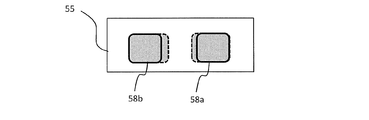
- FIG. 2 schematically shows light source images of the first and second surface light sources 50a and 50b formed on the first imaging surface 55.
- a light source image 58a is a light source image of the first surface light source 50a
- a light source image 58b is a light source image of the second surface light source 50b.
- the light source images 58a and 58b have a line-symmetric shape.
- the light source images 58a and 58b are formed at an interval d.
- the combined surface light source 58 includes light source images 58a and 58b.
- a ratio (H: V) of the horizontal size H and the vertical size V of the combined surface light source 58 is the aspect ratio.
- this aspect ratio is a predetermined aspect that can improve the light utilization efficiency in the optical system after the optical element 57.
- the light source device of this embodiment when applied to a projection display device, there is an effect that the light use efficiency is improved.
- the reflective element 53 can be configured by a V-shaped mirror or a right-angle prism.
- FIG. 3 schematically shows a V-shaped mirror that is an example of the reflective element 53.
- the V-shaped mirror is composed of two reflecting portions 60a and 60b provided so that the reflecting surfaces thereof are perpendicular to each other.
- Each of the reflecting portions 60a and 60b has a reflecting surface formed on the surface opposite to the virtual imaging surface 54 side.
- the reflecting surface and the virtual imaging surface 54 (or the first imaging surface 55) The angle formed is 45 °.
- FIG. 4 schematically shows changes in the light source images 58 a and 58 b when the V-shaped mirror is moved in the direction perpendicular to the first image plane 55.
- the solid line arrow A1 indicates the optical axis (the principal ray of the first light beam) of the first double-sided telecentric optical system 52a
- the solid line arrow A2 indicates the optical axis (first line of the second double-sided telecentric optical system 52b. 2 is the principal ray of the two luminous fluxes.
- Reference numerals Z1 and Z2 denote distances from the intersection with the optical axis A1 on the reflection surface of the reflection part 60a to the virtual imaging plane 54, and reference numerals Z1 ′ and Z2 ′ denote optical axes on the reflection surface of the reflection part 60a.
- the distance from the intersection with A1 to the first image plane 55 is shown.
- the reflecting element 53 When the reflecting element 53 is moved in a direction perpendicular to the first image plane 55, the following conditions are satisfied. (1) The incident angles of the first and second light beams on the reflecting portions 60a and 60b (or the first image plane 55) do not change. (2) The imaging performance of the first and second surface light sources 50a and 50b on the first imaging surface 55 does not change. (3) When vignetting occurs at the apex portion, the areas of the light source images 58a and 58b are reduced. (4) The horizontal width H of the composite surface light source 58 and the distance D between the light source images 58a and 58b are proportional to twice the vertical movement amount of the reflective element 53.
- the first double-sided telecentric optical system 52a and the second two-sided optical system 58a have a predetermined shape that can improve the light use efficiency in the optical system after the optical element 57.
- a telecentric optical system 52b and a reflective element 53 are disposed.
- the reflective element 53 is arranged so that vignetting occurs in the first and second light beams at the apex angles of the reflecting portions 60a and 60b.
- FIG. 5 schematically shows a combined surface light source 58 formed on the first imaging surface 55 when the reflective element 53 is arranged so that vignetting occurs in the first and second light beams.
- the distance D between the light source images 58a and 58b can be made as small as possible.
- the synthetic surface light source 58 into a predetermined shape and reducing the distance D between the light source images 58a and 58b, it is possible to minimize the degradation of light utilization efficiency due to etendue restrictions, and as a result. , High luminance can be achieved.
- F no 2.40486 ( ⁇ F / 2.4) according to the above equation 1.
- Fno the brightness changes with the square of the ratio of the change. Since the current 1.38 type DMD is F / 2.5 ( ⁇ 11.5 ° or less), F / 2.5 will be described below as an example.
- A is the area of the DMD (area of the image forming surface)
- ⁇ the deflection angle of the micromirror.
- vignetting is generated as shown in FIG. 5 in order to minimize degradation of light utilization efficiency.
- This etendue value of 67.5 is close to the etendue value of 63.54.
- E 94.5, which is far from the above-mentioned etendue value of 63.54.
- FIG. 6 schematically shows a right-angle prism which is another example of the reflective element 53.
- the right-angle prism 61 has reflection surfaces 61a and 61b that are perpendicular to each other.
- the angle formed by the reflecting surface 61a and the virtual imaging surface 54 (or the first imaging surface 55) is 45 °.
- the angle formed by the reflecting surface 61b and the virtual imaging surface 54 (or the first imaging surface 55) is also 45 °.
- FIG. 7 schematically shows changes in the light source images 58 a and 58 b when the right-angle prism 61 is moved in a direction perpendicular to the first image plane 55.
- the solid line arrow A1 indicates the optical axis (the principal ray of the first light beam) of the first double-sided telecentric optical system 52a
- the solid line arrow A2 indicates the optical axis (first line of the second double-sided telecentric optical system 52b. 2 is the principal ray of the two luminous fluxes.
- Reference numerals Z1 and Z2 denote distances from the intersection with the optical axis A1 on the reflecting surface 61a to the virtual imaging plane 54, and reference signs Z1 ′ and Z2 ′ denote the first from the intersection with the optical axis A1 on the reflecting surface 61a.
- a distance to one image plane 55 is shown.
- 61 is arranged. Specifically, the right-angle prism 61 is arranged so that vignetting occurs in the first and second light beams at the apex angles of the reflecting surfaces 61a and 61b. Even when the right-angle prism 61 is used, the same effect as that obtained when the V-shaped mirror is used is obtained.
- FIG. 8A schematically shows the positional relationship between the right angle prism 61 and the apex angle portion of the V-shaped mirror when the composite surface light source 58 is formed so as to have a predetermined shape (size) in a state where vignetting has occurred.
- FIG. 8B schematically shows light source images 58a and 58b formed on the first image plane 55 in the state shown in FIG. 8A.
- the apex angle portion of the right-angle prism 61 is a right angle surface, whereas the apex angle portion of the V-shaped mirror (joint portion of the reflecting portions 60a and 60b) is not a right angle surface. Therefore, as shown in FIG. 8A, in the direction perpendicular to the first image plane 55, the apex angle portion of the right-angle prism 61 is higher than the junction portion of the reflection portions 60a and 60b of the V-shaped mirror by the height d1. Is also located on the first imaging plane 55 side. As a result, as shown in FIG.
- the light source images 58a and 58b (broken line) when the right-angle prism 61 is used are larger than the light source images 58a and 58b (solid line) when the V-shaped mirror is used.
- the size of the combined surface light source 58 does not change between the case where the right-angle prism 61 is used and the case where the V-shaped mirror is used, the light source images 58a and 58b (solid lines) become larger, so that light can be captured more efficiently. Light utilization efficiency can be further improved.
- the first and second surface light sources 50a and 50b and the first and second both-side telecentric optical systems 52a and 52b will be specifically described.
- the first light source part composed of the first surface light source 50a and the first both-side telecentric optical system 52a, and the second light source part composed of the second surface light source 50b and the twelfth both-side telecentric optical system 52b They have the same structure.
- Solid-state light sources can be used as the first and second surface light sources 50a and 50b.
- FIG. 9 shows an example of a light source portion using a solid light source.
- the light source portion includes light source units 1a and 1b, condenser lenses 2a and 2b, reflection mirrors 3a, 3b, 4a and 4b, a diffuser plate 5, a light pipe 6 and lenses 7 to 9.
- the light source unit 1a includes solid light sources 11a and 12a that emit light of the same color and a reflection mirror 13a.
- the solid light sources 11a and 12a have the same structure, and include, for example, a plurality of laser diodes (LDs) that output laser light having a center wavelength in a wavelength region of a predetermined color.
- LDs laser diodes
- the reflection mirror 13a is a mirror having a stripe structure in which reflection areas and transmission areas are alternately arranged.
- a stripe-shaped mirror can be formed by vapor-depositing a band-shaped reflective region on a transparent substrate at a predetermined interval.
- Each row of LDs of the solid-state light source 11a and each transmission region of the reflection mirror 13a have a one-to-one correspondence, and the laser light emitted from the LD of each row passes through the corresponding transmission region of the reflection mirror 13a.
- Each row of LDs of the solid-state light source 12a and each reflection region of the reflection mirror 13a have a one-to-one correspondence.
- the reflected laser beam is reflected in the same direction as the traveling direction.
- the laser light transmitted through the transmission region and the laser light reflected by the reflection region are output light of the light source unit 1a, and this output light is incident on the condenser lens 2a.
- the light source unit 1b outputs light of the same color as the light source unit 1a, and includes solid light sources 11b and 12b and a reflection mirror 13b.
- the portion composed of the solid light sources 11b and 12b and the reflection mirror 13b has the same structure as the portion composed of the solid light sources 11a and 12a and the reflection mirror 13a.
- the laser light emitted from the solid light source 11b is transmitted through each transmission region of the reflection mirror 13b, and the laser light emitted from the solid light source 12b is the same as the traveling direction of the laser light transmitted through the transmission region in each reflection region of the reflection mirror 13b. Reflected in the direction.
- the laser light transmitted through the transmission region and the laser light reflected by the reflection region are output light of the light source unit 1b, and this output light is incident on the condenser lens 2b.
- the laser light that has passed through the condenser lens 2 a passes through the reflecting mirrors 3 a and 4 a and the diffusion plate 5 in order and enters the incident surface of the light pipe 6.
- the laser light that has passed through the condenser lens 2 b passes through the reflecting mirrors 3 b and 4 b and the diffusion plate 5 in order and enters the incident surface of the light pipe 6.
- Each of the light source units 1a and 1b can be called a light source unit.
- the condensing lenses 2a and 2b and the reflecting mirrors 3a, 3b, 4a and 4b can be called light folding means.
- the length of the first optical path from the light source unit 1 a to the incident surface of the light pipe 6 is the same as the length of the second optical path from the light source unit 1 b to the incident surface of the light pipe 6.
- the condensing angle of the condensing lens 2a (the angle given by 2 ⁇ when the angle between the optical axis and the outermost light beam of the light beam is ⁇ ) is the same as that of the condensing lens 2b.
- the incident angle of the central ray of the light beam incident on the incident surface of the light pipe 6 in the first optical path is the same as the incident angle of the central beam of the light beam incident on the incident surface of the light pipe 6 in the second optical path.
- the light pipe 6 is composed of a columnar light guide, and one of both end faces of the light guide is an entrance surface, and the other is an exit surface.
- the light enters the entrance surface, and light propagates through the light guide and exits.
- An optical element (light uniformizing element) emitted from the surface.
- the light is reflected a plurality of times inside the light guide so that a uniform surface light source can be formed on the exit surface.
- the condensing lens 2 a condenses the laser light from the light source unit 1 a and makes it incident on the incident surface of the light pipe 6.
- the condensing lens 2 b condenses the laser light from the light source unit 1 b and makes it incident on the incident surface of the light pipe 6. You may comprise so that the condensing position of each condensing lens 2a, 2b on the entrance plane of the light pipe 6 may become the same.
- the lenses 7 to 9 constitute a bilateral telecentric lens.
- This double-sided telecentric lens is the first double-sided telecentric lens 52a or the second double-sided telecentric lens 52b shown in FIG.
- the space around the light pipe 6 is utilized, and the light source units 1a and 1b are arranged in the space, so that the apparatus can be miniaturized.
- the laser light emitted from each of the light source units 1 a and 1 b is folded back and incident on the incident surface of the light pipe 6. In this way, the apparatus can be miniaturized by folding the optical path.
- the configuration of the light source portion described above includes the light source portion including the first surface light source 50a and the first both-side telecentric lens 52a, the second surface light source 50b, and the second both-side telecentric of the light source device shown in FIG.
- the present invention can be applied to the light source portion composed of the lens 52b.
- the exit surface (opening surface) of the light pipe 6 constitutes a surface light emitting portion, and a light source image of this surface light emitting portion is formed on the first image forming surface 55 as a light source image 58a or 58b.
- Each of the first and second surface light sources 50a and 50b may be a phosphor light source using a phosphor.
- the phosphor light source may include an excitation light source that emits excitation light and a fluorescent unit that includes a phosphor that is excited by the excitation light and emits fluorescence. In this case, the phosphor may emit green fluorescence.
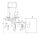
- FIG. 10 shows an example of a light source portion provided with a phosphor light source.
- the light source part includes light source units 21a and 21b, condenser lenses 22a and 22b, reflection mirrors 23a, 23b, 24a, 24b and 34, a diffuser plate 25, a light pipe 26, lenses 27 to 32, and a dichroic mirror. 33 and a fluorescent wheel 35.
- the light source part includes light source units 21a and 21b, condenser lenses 22a and 22b, reflection mirrors 23a, 23b, 24a, 24b and 34, a diffuser plate 25, a light pipe 26, lenses 27 to 32, and a dichroic mirror. 33 and a fluorescent wheel 35.
- FIG. 10 for the sake of convenience, only a part of the ray trajectory is shown.
- the light source units 21a and 21b are excitation light sources for exciting the phosphor, and emit excitation light of the same color.
- the light source unit 21a includes solid light sources 211a and 212a that emit excitation light of the same color and a reflection mirror 213a.
- the solid light sources 211a and 212a have the same structure, and include, for example, a plurality of laser diodes (LDs) that output blue laser light having a center wavelength in a blue wavelength region.
- LDs laser diodes
- (n (rows) ⁇ m (columns)) of blue LDs formed on a holding member provided with a heat radiating portion is used.
- the reflection mirror 213a is a mirror having a stripe structure in which reflection areas and transmission areas are alternately arranged.
- a stripe-shaped mirror can be formed by vapor-depositing a band-shaped reflective region on a transparent substrate at a predetermined interval.
- Each row of blue LDs of the solid-state light source 211a and each transmission region of the reflection mirror 213a have a one-to-one correspondence, and the blue laser light emitted from the blue LD of each row passes through the corresponding transmission region of the reflection mirror 213a. pass.
- Each row of blue LDs of the solid-state light source 212a and each reflection region of the reflection mirror 213a have a one-to-one correspondence, and the blue laser light emitted from the blue LD of each row is reflected by the corresponding reflection region of the reflection mirror 213a.
- the blue laser light that has passed through the transmission region is reflected in the same direction as the traveling direction.
- the blue laser light transmitted through the transmission region and the blue laser light reflected by the reflection region are output light of the light source unit 21a, and this output light is incident on the condenser lens 22a.
- the light source unit 21b includes solid light sources 211b and 212b and a reflection mirror 213b.
- the portion composed of the solid light sources 211b and 212b and the reflection mirror 213b has the same structure as the portion composed of the solid light sources 211a and 212a and the reflection mirror 213a.
- the blue laser light emitted from the solid light source 211b is transmitted through each transmission region of the reflection mirror 213b, and the blue laser light emitted from the solid light source 212b is transmitted through the transmission region in each reflection region of the reflection mirror 213b. Reflected in the same direction as the direction.
- the blue laser light transmitted through the transmission region and the blue laser light reflected by the reflection region are output light of the light source unit 21b, and this output light is incident on the condenser lens 22b.
- the blue laser light that has passed through the condenser lens 22 a passes through the reflecting mirrors 23 a and 24 a and the diffusion plate 25 in order, and enters the incident surface of the light pipe 26.
- the blue laser light that has passed through the condenser lens 22b sequentially passes through the reflection mirrors 23b and 24b and the diffusion plate 25 and enters the incident surface of the light pipe 26.
- the length of the first optical path from the light source unit 21a to the incident surface of the light pipe 26 is the same as the length of the second optical path from the light source unit 21b to the incident surface of the light pipe 26.
- the condensing angle of the condensing lens 22a is the same as that of the condensing lens 22b.
- the incident angle of the central ray of the light beam incident on the incident surface of the light pipe 26 in the first optical path is the same as the incident angle of the central ray of the light beam incident on the incident surface of the light pipe 26 in the second optical path.
- the light pipe 26 is composed of a columnar light guide, and one of both end faces of the light guide is an entrance surface, and the other is an exit surface. Light is incident from the entrance surface and emitted through the light guide. An optical element (light uniformizing element) emitted from the surface. The light is reflected a plurality of times inside the light guide so that a uniform surface light source can be formed on the exit surface.
- a light tunnel having a hollow interior and an inner surface made of a mirror, a rod having a polygonal column made of a transparent material such as glass, or the like can be used.
- the condensing lens 22 a condenses the laser light from the light source unit 21 a and makes it incident on the incident surface of the light pipe 26.
- the condensing lens 22 b condenses the laser light from the light source unit 21 b and makes it incident on the incident surface of the light pipe 26. You may comprise so that the condensing position of each condensing lens 22a, 22b on the entrance plane of the light pipe 26 may become the same.
- the lenses 27 and 28 and the dichroic mirror 33 are arranged in this order in the traveling direction of the blue laser light (blue excitation light) emitted from the emission surface of the light pipe 26.
- the lenses 27 and 28 are condensing lenses.
- the dichroic mirror 33 has a reflection / transmission characteristic that reflects light in the blue wavelength region of the visible light wavelength region and transmits light in other wavelength regions.
- the blue laser light from the light pipe 26 is reflected by the dichroic mirror 33 after passing through the lenses 27 and 28.
- the lenses 29 to 31 and the fluorescent wheel 35 are arranged in this order.
- the lenses 29 to 31 are condensing lenses.
- the fluorescent wheel 35 includes a rotatable circular substrate and a phosphor portion formed along the circumferential direction on the circular substrate.
- the central portion of the circular substrate is supported by the output shaft of the rotary motor, and the rotary motor rotates the circular substrate.
- the phosphor part includes a phosphor that can be excited by blue laser light from the dichroic mirror 33.
- a yellow phosphor that emits yellow fluorescence, a green phosphor that emits green fluorescence, or the like can be used.
- a green phosphor is used.
- the blue laser light from the dichroic mirror 33 passes through the lenses 29 to 31 and then enters the phosphor portion of the fluorescent wheel 35.
- Green fluorescent light (diverging light) emitted from the phosphor part passes through the lenses 29-30.
- the green fluorescence that has passed through the lenses 29 to 30 passes through the dichroic mirror 33.
- the lens 32 and the reflection mirror 34 are arranged in this order in the traveling direction of the green fluorescence (transmitted light) from the dichroic mirror 33.
- the lens 32 is a condenser lens.
- the lenses 27 to 32 collect the blue laser light emitted from the emission surface of the light pipe 26 on the phosphor part of the fluorescent wheel 35. Further, the lenses 29 to 32 act so as to collect the green fluorescence (diverged light) emitted from the phosphor portion. The green fluorescence that has passed through the lens 32 is reflected by the reflection mirror 34. The reflected light (green fluorescence) from the reflection mirror 34 is the output of the light source portion.
- a lens for obtaining a parallel light beam may be disposed in the optical path of green fluorescence that has passed through the lens 32.
- the lenses 27, 28, and 32 and at least one lens provided in the optical path that has passed through the lens 32 constitute a double-sided telecentric lens. This double-sided telecentric lens is the first double-sided telecentric lens 52a or the second double-sided telecentric lens 52b shown in FIG.
- the configuration of the light source portion described above includes the light source portion including the first surface light source 50a and the first both-side telecentric lens 52a, the second surface light source 50b, and the second both-side telecentric of the light source device shown in FIG.
- the present invention can be applied to the light source portion composed of the lens 52b.
- the shape of the exit surface (opening surface) of the light pipe 26 is projected onto the phosphor surface of the fluorescent wheel 35.
- the shape of the spot of blue laser light (excitation light) on the phosphor surface is similar to the shape of the exit surface (opening surface) of the light pipe 26.
- a light source image of a spot on the phosphor surface is imaged on the first imaging surface 55 as a light source image 58a or a light source image 58b.
- each of the first and second surface light sources 50a and 50b may include a plurality of light source units having different emission colors, and the first and second both-side telecentric optical systems 52a and 52b may be provided for each emission color.
- the first optical system 51 includes a first color combining unit that combines a plurality of light beams emitted from the plurality of light source units of the first surface light source 50a and emits the same light path, and a second color combining unit.
- a second color synthesis unit that synthesizes a plurality of light beams emitted from the plurality of light source units of the surface light source 50b and emits the light beams through the same optical path.
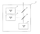
- FIG. 11 shows an example of a light source portion including light sources of red, blue, and green.
- the light source portion 71 includes a green light source part 72, a blue light source part 73, a red light source part 74, and dichroic mirrors 75 and 76.
- the green light source unit 72 has the configuration shown in FIG.
- Each of the red light source unit 74 and the blue light source unit 73 has the configuration shown in FIG.
- the solid light sources 11a, 11b, 12a, and 12b are configured by red LDs.
- the solid light sources 11a, 11b, 12a, and 12b are configured by blue LD.
- the dichroic mirror 75 has a reflection / transmission characteristic that reflects light in the blue wavelength region of the visible light wavelength region and transmits light in other wavelength regions.
- the dichroic mirror 76 has a reflection / transmission characteristic that reflects light in the green wavelength region of the visible light wavelength region and transmits light in other wavelength regions.
- the dichroic mirror 75 is disposed at a position where the optical axis of the red light source unit 74 and the optical axis of the blue light source unit 73 are orthogonal to each other. Red light emitted from the red light source unit 54 is incident on one surface of the dichroic mirror 75, and blue light emitted from the blue light source unit 73 is incident on the other surface of the dichroic mirror 75.
- the angle formed by the optical axis of the red light source 74 and one surface of the dichroic mirror 75 is 45 °, and the angle formed by the optical axis of the blue light source 73 and the other surface of the dichroic mirror 75 is 45 °.
- Red light from the red light source 74 passes through the dichroic mirror 75.
- Blue light from the blue light source unit 73 is reflected by the dichroic mirror 75 in the same direction as the transmitted green light. That is, the dichroic mirror 75 emits first composite light in which red light and blue light are mixed.
- the dichroic mirror 76 is disposed at a position where the optical axis of the red light source unit 54 and the optical axis of the green light source unit 72 are orthogonal to each other.
- the first composite light (blue / green) from the dichroic mirror 75 is incident on one surface of the dichroic mirror 76, and the green light emitted from the green light source unit 72 is incident on the other surface of the dichroic mirror 76.
- the angle formed by the optical axis of the red light source 74 and one surface of the dichroic mirror 76 is 45 °, and the angle formed by the optical axis of the green light source 72 and the other surface of the dichroic mirror 76 is 45 °.
- the first composite light from the dichroic mirror 75 passes through the dichroic mirror 76.
- the green light from the green light source 72 is reflected by the dichroic mirror 76 in the same direction as the transmitted first composite light. That is, the dichroic mirror 76 emits the second composite light (white light) obtained by mixing the first composite light (blue / red) and the green light.
- This second composite light (white light) is the output light of the light source portion 71.
- the light source portion 71 described above includes the light source portion including the first surface light source 50a and the first both-side telecentric lens 52a, the second surface light source 50b, and the second both-side telecentric lens of the light source device shown in FIG. 52b can be applied to each light source portion.
- the order in which the light beams from the green light source unit 72, the red light source unit 74, and the blue light source unit 73 are combined can be appropriately changed. For example, the green light from the green light source 72 and the blue light from the blue light source 73 are combined, and the first composite light obtained by mixing these green light and blue light and the red light from the red light source 74 are combined. You may do it.
- FIG. 12 is a schematic diagram showing a configuration of a light source device according to the second embodiment of the present invention.
- the light source device shown in FIG. 12 is different from the light source device of the first embodiment in that an optical element 157 is provided instead of the optical element 57.
- the first and second surface light sources 50a and 50b, the first optical system 51, and the second optical system 56 are basically the same as those in the first embodiment. Below, the structure of a light source device is demonstrated supposing illuminating a liquid crystal panel.
- the optical element 157 can be called an integrator.
- the optical element 157 is a fly-eye lens composed of a plurality of minute lenses, and includes a first fly-eye lens 157a and a second fly-eye lens 157b.
- the minute lenses of the first fly-eye lens 157a and the minute lenses of the second fly-eye lens 157b are arranged to face each other.
- the light beam incident on the first fly-eye lens 157a is divided into the number of minute lenses of the first fly-eye lens 157a.
- Each minute lens of the first fly-eye lens 157a has a similar shape to the effective display area of the liquid crystal panel and the area to which + ⁇ of the illumination area adjustment is added, and the light beam from the light source is transmitted to the second fly-eye lens.
- Each micro lens of the second fly-eye lens 157b forms an image of the corresponding micro lens of the first fly-eye lens 157a on the liquid crystal panel.
- the effective shape a shape composed of a plurality of microlenses
- the first fly's eye lens 157a is irradiated with a light beam may or may not be similar to the shape of each microlens.
- the first optical system 51 forms the light source images of the first and second surface light sources 50a and 50b in different regions on the first image formation surface 55.
- the first optical system 51 includes a reflecting element 53, a first both-side telecentric optical system 52a, and a second both-side telecentric optical system 52b.
- the reflective element 53 includes first and second reflective surfaces 53a and 53b provided so as to be perpendicular to each other.
- the first both-side telecentric optical system 52a is provided on the optical path between the first surface light source 50a and the first reflection surface 53a, and the light source image of the first surface light source 50a is displayed on the first reflection surface.
- An image is formed on the first image plane 55 via 53a.
- the second both-side telecentric optical system 52b is provided on the optical path between the second surface light source 50b and the second reflection surface 53b, and the light source image of the second surface light source 50b is used as the second reflection surface.
- An image is formed on the first image plane 55 via 53b.
- the first both-side telecentric optical system 52 a and the second both-side telecentric optical system 52 b have the same structure, and are arranged so that their emission surfaces face each other with the reflective element 53 interposed therebetween.
- the principal ray (optical axis) of the first light beam from the first both-side telecentric optical system 52a and the principal ray (optical axis) of the second light beam from the second both-side telecentric optical system 52b are on the same axis. I'm doing it.
- the virtual imaging plane 54 indicates an imaging plane in the state where the first and second reflecting surfaces 53a and 53b are not interposed in the first both-side telecentric optical system 52a and the second both-side telecentric optical system 52b, respectively.
- the virtual imaging plane 54 and the first imaging plane 55 are orthogonal to each other.
- the angle formed between the first reflecting surface 53a and the virtual imaging surface 54 is 45 °, and the angle formed between the principal ray of the light beam from the first both-side telecentric optical system 52a and the first reflecting surface 53a is 45 °. It is.
- the angle formed between the second reflecting surface 53b and the virtual imaging surface 54 is 45 °, and the angle formed between the principal ray of the light beam from the second both-side telecentric optical system 52b and the second reflecting surface 53b. Is also 45 °.
- the first reflecting surface 53a and the second reflecting surface 53b reflect the first light beam from the first both-side telecentric optical system 52a and the second light beam from the second both-side telecentric optical system 52b in the same direction. .
- the principal ray of the first light beam from the first both-side telecentric optical system 52a and the principal ray of the second light beam from the second both-side telecentric optical system 52b are located on the same axis.
- the apex angle portion which is the junction of the first and second reflecting surfaces 53a, 53b, is You may arrange
- the second optical system 56 and the first fly-eye lens 57a convert the combined surface light source composed of the light source images of the first and second surface light sources formed on the first image forming surface 55 into the second fly. An image is formed in the vicinity of the eye lens 57b.
- the second optical system 56 may include a third double-sided telecentric lens optical system.
- the light source image 58a is a light source image of the first surface light source 50a
- the light source image 58b is a light source image of the second surface light source 50b.
- the light source images 58a and 58b have a line-symmetric shape.
- the light source images 58a and 58b are formed at an interval d.
- the combined surface light source 58 includes light source images 58a and 58b.
- the reflecting element 53 can be configured by a V-shaped mirror or a right-angle prism.
- the V-shaped mirror shown in FIG. 3 can be used as the reflective element 53.
- the V-shaped mirror is composed of two reflecting portions 60a and 60b provided so that the reflecting surfaces thereof are perpendicular to each other.
- Each of the reflecting portions 60a and 60b has a reflecting surface formed on the surface opposite to the virtual imaging surface 54 side.
- the reflecting surface and the virtual imaging surface 54 (or the first imaging surface 55) The angle formed is 45 °.
- the interval between the images 58a and 58b is also widened.
- the composite surface is considered in consideration of the conditions (1) to (4) in the case where the reflecting element 53 is moved in the direction perpendicular to the first image plane 55 described in the first embodiment.
- the first both-side telecentric optical system 52a, the second both-side telecentric optical system 52b, and the reflecting element 53 are arranged so that the light source 58 has a predetermined shape that can improve the light utilization efficiency in the optical system after the optical element 57. Be placed.
- the reflective element 53 is arranged so that vignetting occurs in the first and second light beams at the apex angles of the reflecting portions 60a and 60b.
- the combined surface light source 58 shown in FIG. 5 is formed on the first imaging surface 55.
- the distance D between the light source images 58a and 58b it is possible to minimize the degradation of light utilization efficiency due to etendue restrictions, and as a result, it is possible to achieve high brightness.
- Equation 1 The F value (F number) of the projection lens is given by Equation 1 described above.
- ⁇ is a light beam spread angle (half value).
- F / 1.7 the F value of the projection lens is mainly about 1.7.
- Etendue is given by Equation 2 above.
- A is the area (effective display area) of the liquid crystal panel, and ⁇ is a half angle of the F value of the projection lens.
- vignetting is generated as shown in FIG. 5 in order to minimize degradation of light utilization efficiency.
- This etendue value of 67.5 is close to the etendue value of 50.4.
- the right-angle prism shown in FIG. 6 can be used in this embodiment.
- the right-angle prism 61 has reflection surfaces 61a and 61b that are perpendicular to each other.
- the angle formed by the reflecting surface 61a and the virtual imaging surface 54 (or the first imaging surface 55) is 45 °.
- the angle formed by the reflecting surface 61b and the virtual imaging surface 54 (or the first imaging surface 55) is also 45 °.
- the light source images 58a and 58b change as shown in FIG.
- the interval between the images 58a and 58b is also widened.
- 61 is arranged. Specifically, the right-angle prism 61 is arranged so that vignetting occurs in the first and second light beams at the apex angles of the reflecting surfaces 61a and 61b. Even when the right-angle prism 61 is used, the same effect as that obtained when the V-shaped mirror is used is obtained.
- the apex angle portion of the right-angle prism 61 is a right-angle surface
- the apex angle portion of the V-shaped mirror is a right-angle surface. It is not.
- the apex angle portion of the right-angle prism 61 is the height d1 and the junction portion of the reflection portions 60a and 60b of the V-shaped mirror. It is located on the first image plane 55 side.
- the light source images 58a and 58b (broken line) when the right-angle prism 61 is used are larger than the light source images 58a and 58b (solid line) when the V-shaped mirror is used.
- the size of the combined surface light source 58 does not change between the case where the right-angle prism 61 is used and the case where the V-shaped mirror is used, the light source images 58a and 58b (solid lines) become larger, so that light can be captured more efficiently. Light utilization efficiency can be further improved.
- the first and second surface light sources 50a and 50b and the first and second both-side telecentric optical systems 52a and 52b will be specifically described.
- the first light source part composed of the first surface light source 50a and the first both-side telecentric optical system 52a, and the second light source part composed of the second surface light source 50b and the twelfth both-side telecentric optical system 52b They have the same structure.
- Solid-state light sources can be used as the first and second surface light sources 50a and 50b.
- the structure of the light source part shown in FIG. 9 can be used for the solid light source.
- the light source portion includes light source units 1a and 1b, condenser lenses 2a and 2b, reflection mirrors 3a, 3b, 4a and 4b, a diffuser plate 5, a light pipe 6 and lenses 7 to 9.
- the light source unit 1a includes solid light sources 11a and 12a that emit light of the same color and a reflection mirror 13a.
- the solid light sources 11a and 12a have the same structure, and include, for example, a plurality of laser diodes (LDs) that output laser light having a center wavelength in a wavelength region of a predetermined color.
- LDs laser diodes
- the reflection mirror 13a is a mirror having a stripe structure in which reflection areas and transmission areas are alternately arranged.
- a stripe-shaped mirror can be formed by vapor-depositing a band-shaped reflective region on a transparent substrate at a predetermined interval.
- Each row of LDs of the solid-state light source 11a and each transmission region of the reflection mirror 13a have a one-to-one correspondence, and the laser light emitted from the LD of each row passes through the corresponding transmission region of the reflection mirror 13a.
- Each row of LDs of the solid-state light source 12a and each reflection region of the reflection mirror 13a have a one-to-one correspondence.
- the reflected laser beam is reflected in the same direction as the traveling direction.
- the laser light transmitted through the transmission region and the laser light reflected by the reflection region are output light of the light source unit 1a, and this output light is incident on the condenser lens 2a.
- the light source unit 1b outputs light of the same color as the light source unit 1a, and includes solid light sources 11b and 12b and a reflection mirror 13b.
- the portion composed of the solid light sources 11b and 12b and the reflection mirror 13b has the same structure as the portion composed of the solid light sources 11a and 12a and the reflection mirror 13a.
- the laser light emitted from the solid light source 11b is transmitted through each transmission region of the reflection mirror 13b, and the laser light emitted from the solid light source 12b is the same as the traveling direction of the laser light transmitted through the transmission region in each reflection region of the reflection mirror 13b. Reflected in the direction.
- the laser light transmitted through the transmission region and the laser light reflected by the reflection region are output light of the light source unit 1b, and this output light is incident on the condenser lens 2b.
- the laser light that has passed through the condenser lens 2 a passes through the reflecting mirrors 3 a and 4 a and the diffusion plate 5 in order and enters the incident surface of the light pipe 6.
- the laser light that has passed through the condenser lens 2 b passes through the reflecting mirrors 3 b and 4 b and the diffusion plate 5 in order and enters the incident surface of the light pipe 6.
- Each of the light source units 1a and 1b can be called a light source unit.
- the condensing lenses 2a and 2b and the reflecting mirrors 3a, 3b, 4a and 4b can be called light folding means.
- the length of the first optical path from the light source unit 1 a to the incident surface of the light pipe 6 is the same as the length of the second optical path from the light source unit 1 b to the incident surface of the light pipe 6.
- the condensing angle of the condensing lens 2a (the angle given by 2 ⁇ when the angle between the optical axis and the outermost light beam of the light beam is ⁇ ) is the same as that of the condensing lens 2b.
- the incident angle of the central ray of the light beam incident on the incident surface of the light pipe 6 in the first optical path is the same as the incident angle of the central beam of the light beam incident on the incident surface of the light pipe 6 in the second optical path.
- the light pipe 6 is composed of a columnar light guide, and one of both end faces of the light guide is an entrance surface, and the other is an exit surface.
- the light enters the entrance surface, and light propagates through the light guide and exits.
- An optical element (light uniformizing element) emitted from the surface.
- the light is reflected a plurality of times inside the light guide so that a uniform surface light source can be formed on the exit surface.
- the condensing lens 2 a condenses the laser light from the light source unit 1 a and makes it incident on the incident surface of the light pipe 6.
- the condensing lens 2 b condenses the laser light from the light source unit 1 b and makes it incident on the incident surface of the light pipe 6. You may comprise so that the condensing position of each condensing lens 2a, 2b on the entrance plane of the light pipe 6 may become the same.
- the lenses 7 to 9 constitute a bilateral telecentric lens.
- This double-sided telecentric lens is the first double-sided telecentric lens 52a or the second double-sided telecentric lens 52b shown in FIG.
- the space around the light pipe 6 is utilized, and the light source units 1a and 1b are arranged in the space, so that the apparatus can be miniaturized.
- the laser light emitted from each of the light source units 1 a and 1 b is folded back and incident on the incident surface of the light pipe 6. In this way, the apparatus can be miniaturized by folding the optical path.
- the configuration of the light source portion described above is the same as that of the light source device shown in FIG. 12, the light source portion including the first surface light source 50 a and the first both-side telecentric lens 52 a, the second surface light source 50 b and the second both-side telecentric.
- the present invention can be applied to the light source portion composed of the lens 52b.
- the exit surface (opening surface) of the light pipe 6 constitutes a surface light emitting portion, and a light source image of this surface light emitting portion is formed on the first image forming surface 55 as a light source image 58a or 58b.
- Each of the first and second surface light sources 50a and 50b may be a phosphor light source using a phosphor.
- the phosphor light source may include an excitation light source that emits excitation light and a fluorescent unit that includes a phosphor that is excited by the excitation light and emits fluorescence. In this case, the phosphor may emit green fluorescence.
- the light source part provided with the phosphor light source shown in FIG. 10 can be used.
- the light source portion includes light source units 21a and 21b, condenser lenses 22a and 22b, reflection mirrors 23a, 23b, 24a, 24b and 34, a diffuser plate 25, a light pipe 26, lenses 27 to 32, A dichroic mirror 33 and a fluorescent wheel 35 are provided.
- the light source units 21a and 21b are excitation light sources for exciting the phosphor, and emit excitation light of the same color.
- the light source unit 21a includes solid light sources 211a and 212a that emit excitation light of the same color and a reflection mirror 213a.
- the solid light sources 211a and 212a have the same structure, and include, for example, a plurality of laser diodes (LDs) that output blue laser light having a center wavelength in a blue wavelength region.
- LDs laser diodes
- (n (rows) ⁇ m (columns)) of blue LDs formed on a holding member provided with a heat radiating portion is used.
- the reflection mirror 213a is a mirror having a stripe structure in which reflection areas and transmission areas are alternately arranged.
- a stripe-shaped mirror can be formed by vapor-depositing a band-shaped reflective region on a transparent substrate at a predetermined interval.
- Each row of blue LDs of the solid-state light source 211a and each transmission region of the reflection mirror 213a have a one-to-one correspondence, and the blue laser light emitted from the blue LD of each row passes through the corresponding transmission region of the reflection mirror 213a. pass.
- Each row of blue LDs of the solid-state light source 212a and each reflection region of the reflection mirror 213a have a one-to-one correspondence, and the blue laser light emitted from the blue LD of each row is reflected by the corresponding reflection region of the reflection mirror 213a.
- the blue laser light that has passed through the transmission region is reflected in the same direction as the traveling direction.
- the blue laser light transmitted through the transmission region and the blue laser light reflected by the reflection region are output light of the light source unit 21a, and this output light is incident on the condenser lens 22a.
- the light source unit 21b includes solid light sources 211b and 212b and a reflection mirror 213b.
- the portion composed of the solid light sources 211b and 212b and the reflection mirror 213b has the same structure as the portion composed of the solid light sources 211a and 212a and the reflection mirror 213a.
- the blue laser light emitted from the solid light source 211b is transmitted through each transmission region of the reflection mirror 213b, and the blue laser light emitted from the solid light source 212b is transmitted through the transmission region in each reflection region of the reflection mirror 213b. Reflected in the same direction as the direction.
- the blue laser light transmitted through the transmission region and the blue laser light reflected by the reflection region are output light of the light source unit 21b, and this output light is incident on the condenser lens 22b.
- the blue laser light that has passed through the condenser lens 22 a passes through the reflecting mirrors 23 a and 24 a and the diffusion plate 25 in order, and enters the incident surface of the light pipe 26.
- the blue laser light that has passed through the condenser lens 22b sequentially passes through the reflection mirrors 23b and 24b and the diffusion plate 25 and enters the incident surface of the light pipe 26.
- the length of the first optical path from the light source unit 21a to the incident surface of the light pipe 26 is the same as the length of the second optical path from the light source unit 21b to the incident surface of the light pipe 26.
- the condensing angle of the condensing lens 22a is the same as that of the condensing lens 22b.
- the incident angle of the central ray of the light beam incident on the incident surface of the light pipe 26 in the first optical path is the same as the incident angle of the central ray of the light beam incident on the incident surface of the light pipe 26 in the second optical path.
- the light pipe 26 is composed of a columnar light guide, and one of both end faces of the light guide is an entrance surface, and the other is an exit surface. Light is incident from the entrance surface and emitted through the light guide. An optical element (light uniformizing element) emitted from the surface. The light is reflected a plurality of times inside the light guide so that a uniform surface light source can be formed on the exit surface.
- a light tunnel having a hollow interior and an inner surface made of a mirror, a rod having a polygonal column made of a transparent material such as glass, or the like can be used.
- the condensing lens 22 a condenses the laser light from the light source unit 21 a and makes it incident on the incident surface of the light pipe 26.
- the condensing lens 22 b condenses the laser light from the light source unit 21 b and makes it incident on the incident surface of the light pipe 26. You may comprise so that the condensing position of each condensing lens 22a, 22b on the entrance plane of the light pipe 26 may become the same.
- the lenses 27 and 28 and the dichroic mirror 33 are arranged in this order in the traveling direction of the blue laser light (blue excitation light) emitted from the emission surface of the light pipe 26.
- the lenses 27 and 28 are condensing lenses.
- the dichroic mirror 33 has a reflection / transmission characteristic that reflects light in the blue wavelength region of the visible light wavelength region and transmits light in other wavelength regions.
- the blue laser light from the light pipe 26 is reflected by the dichroic mirror 33 after passing through the lenses 27 and 28.
- the lenses 29 to 31 and the fluorescent wheel 35 are arranged in this order.
- the lenses 29 to 31 are condensing lenses.
- the fluorescent wheel 35 includes a rotatable circular substrate and a phosphor portion formed along the circumferential direction on the circular substrate.
- the central portion of the circular substrate is supported by the output shaft of the rotary motor, and the rotary motor rotates the circular substrate.
- the phosphor part includes a phosphor that can be excited by blue laser light from the dichroic mirror 33.
- a yellow phosphor that emits yellow fluorescence, a green phosphor that emits green fluorescence, or the like can be used.
- a green phosphor is used.
- the blue laser light from the dichroic mirror 33 passes through the lenses 29 to 31 and then enters the phosphor portion of the fluorescent wheel 35.
- Green fluorescent light (diverging light) emitted from the phosphor part passes through the lenses 29-30.
- the green fluorescence that has passed through the lenses 29 to 30 passes through the dichroic mirror 33.
- the lens 32 and the reflection mirror 34 are arranged in this order in the traveling direction of the green fluorescence (transmitted light) from the dichroic mirror 33.
- the lens 32 is a condenser lens.
- the lenses 27 to 32 collect the blue laser light emitted from the emission surface of the light pipe 26 on the phosphor part of the fluorescent wheel 35. Further, the lenses 29 to 32 act so as to collect the green fluorescence (diverged light) emitted from the phosphor portion. The green fluorescence that has passed through the lens 32 is reflected by the reflection mirror 34. The reflected light (green fluorescence) from the reflection mirror 34 is the output of the light source portion.
- a lens for obtaining a parallel light beam may be disposed in the optical path of green fluorescence that has passed through the lens 32.
- the lenses 27, 28, and 32 and at least one lens provided in the optical path that has passed through the lens 32 constitute a double-sided telecentric lens. This double-sided telecentric lens is the first double-sided telecentric lens 52a or the second double-sided telecentric lens 52b shown in FIG.
- the configuration of the light source portion described above is the same as that of the light source device shown in FIG. 12, the light source portion including the first surface light source 50 a and the first both-side telecentric lens 52 a, the second surface light source 50 b and the second both-side telecentric.
- the present invention can be applied to the light source portion composed of the lens 52b.
- the shape of the exit surface (opening surface) of the light pipe 26 is projected onto the phosphor surface of the fluorescent wheel 35.
- the shape of the spot of blue laser light (excitation light) on the phosphor surface is similar to the shape of the exit surface (opening surface) of the light pipe 26.
- a light source image of a spot on the phosphor surface is imaged on the first imaging surface 55 as a light source image 58a or a light source image 58b.
- the first and second surface light sources 50a and 50b and the first and second both-side telecentric optical systems 52a and 52b may have the following configurations.
- Each of the first and second surface light sources 50a and 50b may include a plurality of light source units having different emission colors, and the first and second both-side telecentric optical systems 52a and 52b may be provided for each emission color.
- the first optical system 51 includes a first color combining unit that combines a plurality of light beams emitted from the plurality of light source units of the first surface light source 50a and emits the same light path, and a second color combining unit.
- a second color synthesis unit that synthesizes a plurality of light beams emitted from the plurality of light source units of the surface light source 50b and emits the light beams through the same optical path.
- the light source portion 71 includes a green light source unit 72, a blue light source unit 73, a red light source unit 74, and dichroic mirrors 75 and 76.
- the green light source unit 72 has the configuration shown in FIG.
- Each of the red light source unit 74 and the blue light source unit 73 has the configuration shown in FIG.
- the solid light sources 11a, 11b, 12a, and 12b are configured by red LDs.
- the solid light sources 11a, 11b, 12a, and 12b are configured by blue LD.
- the dichroic mirror 75 has a reflection / transmission characteristic that reflects light in the blue wavelength region of the visible light wavelength region and transmits light in other wavelength regions.
- the dichroic mirror 76 has a reflection / transmission characteristic that reflects light in the green wavelength region of the visible light wavelength region and transmits light in other wavelength regions.
- the dichroic mirror 75 is disposed at a position where the optical axis of the red light source unit 74 and the optical axis of the blue light source unit 73 are orthogonal to each other. Red light emitted from the red light source unit 54 is incident on one surface of the dichroic mirror 75, and blue light emitted from the blue light source unit 73 is incident on the other surface of the dichroic mirror 75.
- the angle formed by the optical axis of the red light source 74 and one surface of the dichroic mirror 75 is 45 °, and the angle formed by the optical axis of the blue light source 73 and the other surface of the dichroic mirror 75 is 45 °.
- Red light from the red light source 74 passes through the dichroic mirror 75.
- Blue light from the blue light source unit 73 is reflected by the dichroic mirror 75 in the same direction as the transmitted green light. That is, the dichroic mirror 75 emits first composite light in which red light and blue light are mixed.
- the dichroic mirror 76 is disposed at a position where the optical axis of the red light source unit 54 and the optical axis of the green light source unit 72 are orthogonal to each other.
- the first composite light (blue / green) from the dichroic mirror 75 is incident on one surface of the dichroic mirror 76, and the green light emitted from the green light source unit 72 is incident on the other surface of the dichroic mirror 76.
- the angle formed by the optical axis of the red light source 74 and one surface of the dichroic mirror 76 is 45 °, and the angle formed by the optical axis of the green light source 72 and the other surface of the dichroic mirror 76 is 45 °.
- the first composite light from the dichroic mirror 75 passes through the dichroic mirror 76.
- the green light from the green light source 72 is reflected by the dichroic mirror 76 in the same direction as the transmitted first composite light. That is, the dichroic mirror 76 emits the second composite light (white light) obtained by mixing the first composite light (blue / red) and the green light.
- This second composite light (white light) is the output light of the light source portion 71.
- the light source portion 71 described above includes the light source portion including the first surface light source 50a and the first both-side telecentric lens 52a, the second surface light source 50b, and the second both-side telecentric lens of the light source device shown in FIG. 52b can be applied to each light source portion.
- the order in which the light beams from the green light source unit 72, the red light source unit 74, and the blue light source unit 73 are combined can be appropriately changed. For example, the green light from the green light source 72 and the blue light from the blue light source 73 are combined, and the first composite light obtained by mixing these green light and blue light and the red light from the red light source 74 are combined. You may do it.
- the diffuser plate currently used by each of the red light source part 74 and the blue light source part 73 can also be shared.
- a diffuser plate common to the red light source unit 74 and the blue light source unit 73 may be provided on the optical path between the dichroic mirror 75 and the dichroic mirror 76.
- the diffusion plate may be vibrated to suppress speckle.
- the light source device of the present embodiment includes first and second light sources and a first optical system that forms light source images of the first and second light sources in different regions on the same imaging plane.
- the first optical system has a first reflecting surface that reflects the first light beam from the first light source toward the imaging surface, and a second light beam from the second light source toward the imaging surface. And a second reflecting surface for reflecting.
- the apex angle portion which is the junction of the first and second reflecting surfaces, is incident on the first reflecting surface.
- the first light source and the second light source may be configured using, for example, the first surface light source 50a and the first surface light source 50a shown in FIG.
- the reflective element constituting the first optical system may be configured using the reflective element 53 shown in FIG. 1 or FIG.
- the first and second reflection surfaces are the first reflection surface 53a and the second reflection surface 53b.
- the apex angle portion which is a joint portion of the first and second reflecting surfaces 53a, 53b, is the first And it arrange
- the light source device of the present embodiment includes first and second light sources and a first optical system that forms light source images of the first and second light sources in different regions on the same imaging plane.
- the first optical system has a first reflecting surface that reflects the first light beam from the first light source toward the imaging surface, and a second light beam from the second light source toward the imaging surface.
- a second reflecting surface that reflects, a part of the first light beam is not reflected by the first reflecting surface, and a part of the second light beam is the second reflecting surface. It is comprised so that it may not be reflected by.
- the first light source and the second light source may be configured using, for example, the first surface light source 50a and the first surface light source 50a shown in FIG.
- the reflective element constituting the first optical system may be configured using the reflective element 53 shown in FIG. 1 or FIG.
- the first and second reflection surfaces are the first reflection surface 53a and the second reflection surface 53b.
- a part of the first light flux from the first surface light source 50a is not reflected by the first reflecting surface 53a.
- a part of the second light flux from the second surface light source 50b is not reflected by the second reflecting surface 53b.
- a second optical system into which a light beam from a combined light source composed of light source images of the first and second light sources formed on the imaging surface is incident;
- An integrator that includes an incident surface on which a light beam from the second optical system is incident and that forms a uniform surface light source may be further included.
- the second optical system may be configured to form a light source image of the combined light source on the incident surface.
- the integrator includes at least one of a fly-eye lens, a rod, and a light tunnel.
- the projection display device includes a light source device according to any of the first to fourth embodiments described above, a display element that modulates light output from the light source device to form an image, and the display element.
- the display element a liquid crystal display panel or DMD can be used.
- FIG. 13 schematically shows the configuration of the first projection display device.
- the first projection display device is a three-plate projector, and includes a light source device 601 including a light source portion 71 to which the light source device of the first embodiment is applied. In FIG. 13, for convenience, each part of the light source device 601 is not shown.
- White light emitted from the optical element 57 of the light source device 601 enters a TIR (Total Internal Reflection) prism 605 via lenses 602 and 603 and a reflection mirror 604.
- the optical element 57 there can be used a light tunnel having a hollow interior and an inner surface made of a mirror, a rod having a polygonal column formed of a transparent material such as glass, and the like.
- the TIR prism 605 is a total reflection prism assembly having a total reflection surface therein, and includes two triangular prisms.
- One triangular prism is a right-angle prism, and has first and second surfaces that form a right-angle side and a third surface that forms an oblique side.
- the other triangular prism has first to third surfaces constituting each line segment of the triangle.
- the third surface of the right-angle prism is disposed so as to face the first surface of the other triangular prism.
- the first surface of the right-angle prism is the incident surface of the TIR prism 605.
- the color prism 606 is disposed so as to face the second surface of the right-angle prism.
- the second surface of the other triangular prism is the exit surface of the TIR prism 605 and is parallel to the second surface of the right-angle prism.
- a projection lens 610 is disposed on the exit surface side.
- Light (white light) from the reflection mirror 604 enters the incident surface of the TIR prism 605.
- the light incident on the TIR prism 605 is totally reflected by the internal total reflection surface and is emitted from the second surface of the right-angle prism.
- the light emitted from the second surface enters the color prism 606.
- the color prism 606 includes a plurality of prisms and has first to fourth surfaces.
- the first surface faces the second surface of the right-angle prism of the TIR prism 605.
- the red display panel 608 is disposed to face the second surface
- the green display panel 607 is disposed to face the third surface
- the blue display panel 609 is opposed to the fourth surface.
- red light is emitted from the second surface
- green light is emitted from the third surface
- blue light is emitted from the fourth surface.
- a DMD digital mirror device
- liquid crystal display panel may be used as the display panels 607 to 609.
- Each of the display panels 607 to 609 has an image forming area composed of a plurality of micromirrors arranged in a matrix.
- the micromirror is configured such that the angle changes according to the drive voltage, and the reflection angle differs between when the drive voltage indicating the on state is supplied and when the drive voltage indicating the off state is supplied.
- Red light emitted from the second surface enters the red display panel 608.
- the red display panel 608 spatially modulates the incident red light to form a red image.
- Red image light is incident on the second surface of the color prism 606 from the red display panel 608.
- the red image light incident from the second surface is emitted from the first surface.
- the red image light emitted from the first surface is incident on the second surface of the right-angle prism of the TIR prism 605.
- the green light emitted from the third surface enters the green display panel 607.
- the green display panel 607 spatially modulates the incident green light to form a green image.
- Green image light is incident on the third surface of the color prism 606 from the green display panel 607.
- the green image light incident from the third surface is emitted from the first surface.
- the green image light emitted from the first surface is incident on the second surface of the right-angle prism of the TIR prism 605.
- the blue light emitted from the fourth surface enters the blue display panel 609.
- the blue display panel 609 spatially modulates incident blue light to form a blue image.
- Blue image light enters the fourth surface of the color prism 606 from the blue display panel 609.
- the blue image light incident from the fourth surface is emitted from the first surface.
- the blue image light emitted from the first surface is incident on the second surface of the right-angle prism of the TIR prism 605.
- the red image light, the green image light, and the blue image light incident from the second surface of the right-angle prism are emitted toward the projection lens 610 from the emission surface.
- the projection lens 610 projects the red image, the green image, and the blue image formed on the red display panel 608, the green display panel 607, and the blue display panel 609, respectively, onto the screen.
- the projection lens 610 is an enlarged projection optical system composed of a plurality of lenses.
- a first light source portion including a first surface light source 50a and a first both-side telecentric optical system 52a
- a second light source portion including a second surface light source 50b and a twelfth both-side telecentric optical system 52b.
- the light source portions have the same structure. Thereby, in the illumination light that illuminates the DMD, it is possible to suppress color unevenness caused by different in-plane distributions of red, blue, and green.
- the shape and size of the spot on the phosphor surface are determined by the intensity (light density) of excitation light on the phosphor, the capture angle of the light beam emitted from the phosphor, the incident angle of the light beam on the optical element 57, the optical element
- the design is appropriately made based on the aspect ratio of the incident surface 57, the configuration of the optical system in the optical path from the phosphor to the optical element 57, and the like.
- the reflection surface inside the light guide portion 57a constituting the optical element 57 is tapered, the area of the surface light source is slightly increased, but the divergence angle of light emitted from the emission surface can be reduced. As a result, the loss of incident light with respect to the optical component having a predetermined size can be reduced.
- FIG. 14 schematically shows the configuration of the second projection display device.
- the second projection display device is a three-plate projector, and includes a light source device 501 including a light source portion 71 to which the light source device of the second embodiment is applied. In FIG. 14, for convenience, each part of the light source device 501 is not shown.
- White light emitted from the light source device 501 enters the polarization conversion element 502 via the first fly-eye lens 57a and the second fly-eye lens 57b.
- the polarization conversion element 502 is disposed in the vicinity of the second fly-eye lens 57b.
- FIG. 15 shows the configuration of the polarization conversion element 502. As shown in FIG.
- the polarization conversion element 502 includes a polarization separation film 502a that reflects P-polarized light and transmits S-polarized light, and a half-wave plate 502b.
- white light random polarization
- the polarization separation film 502a separates random polarized light into P-polarized light and S-polarized linearly polarized light.
- the P-polarized light that has passed through the polarization separation film 502a passes through the half-wave plate 502b.
- the half-wave plate 502b rotates the polarization direction of the incident P-polarized light by 90 degrees and emits it as S-polarized light.
- the S-polarized light reflected by the polarization separation film 502a is reflected again by the adjacent polarization separation film 502a and emitted while maintaining the polarization. In this way, the polarization direction is aligned in a single direction.
- the dichroic mirror 504 has a characteristic of reflecting light in the red wavelength region of visible light and transmitting light in other wavelength regions. Of the light emitted from the polarization conversion element 502, red light is reflected by the dichroic mirror 504. The reflected light (red) of the dichroic mirror 504 is incident on the liquid crystal panel 507 via the field lens 505, the reflecting mirror 506, and the polarizing plate 517. Light transmitted through the dichroic mirror 504 (green and blue) enters the dichroic mirror 509.
- the dichroic mirror 509 has a characteristic of reflecting light in the green wavelength region of visible light and transmitting light in other wavelength regions. Green light out of the light emitted from the polarization conversion element 502 is reflected by the dichroic mirror 509 after passing through the dichroic mirror 504. Reflected light (green) of the dichroic mirror 509 is incident on the liquid crystal panel 510 via the polarizing plate 518. Blue light out of the light emitted from the polarization conversion element 502 is transmitted through the dichroic mirrors 504 and 509, respectively.
- the transmitted light (blue) of the dichroic mirror 509 is incident on the liquid crystal panel 516 through the relay lens 511, the reflection mirror 512, the relay lens 513, the reflection mirror 514, the relay lens 515, and the polarizing plate 519.
- the superimposing lens 503 and the field lenses 505 and 508 direct chief rays from the microlenses of the first fly-eye lens 57a toward the center of the liquid crystal panels 507 and 510, and images the microlenses on the liquid crystal panels 507 and 510. Overlapping with. Between the dichroic mirror 509 and the relay lens 511, a rectangular uniform illumination image is formed by superimposing the images of the minute lenses of the first fly-eye lens 57a.
- a relay optical system including the relay lens 511, the reflection mirror 512, the relay lens 513, the reflection mirror 514, and the relay lens 515 is an equal-magnification image of a rectangular uniform illumination image formed between the dichroic mirror 509 and the relay lens 511.
- a polarizing plate 517 and a polarizing plate 520 are respectively disposed on the incident surface side and the emission surface side of the liquid crystal panel 507. Using these polarizing plates 517 and 520, gradation characteristics corresponding to the spatial modulation of the liquid crystal panel 507 are obtained.
- a polarizing plate 518 and a polarizing plate 521 are disposed on the incident surface side and the emitting surface side of the liquid crystal panel 510, respectively, and a polarizing plate 519 and a polarizing plate 522 are disposed on the incident surface side and the emitting surface side of the liquid crystal panel 516, respectively.
- the cross dichroic prism 523 has first to third entrance surfaces and an exit surface.
- the liquid crystal panel 507 is disposed to face the first incident surface of the cross dichroic prism 523.
- the liquid crystal panel 510 is disposed to face the second incident surface of the cross dichroic prism 523.
- the liquid crystal panel 516 is disposed to face the third incident surface of the cross dichroic prism 523.
- the liquid crystal panels 507, 510, and 516 spatially modulate incident light.
- Light emitted from the liquid crystal panel 507 (red) is incident on the first incident surface of the cross dichroic prism 523 via the polarizing plate 520.
- Light emitted from the liquid crystal panel 510 (green) is incident on the second incident surface of the cross dichroic prism 523 via the polarizing plate 521.
- Light emitted from the liquid crystal panel 516 blue enters the third incident surface of the cross dichroic prism 523 via the polarizing plate 522.
- the red light incident from the first incident surface, the green light incident from the second incident surface, and the blue light incident from the third incident surface overlap each other and exit from the exit surface.
- the cross dichroic prism 523 synthesizes and emits red image light, green image light, and blue image light from the liquid crystal panels 507, 510, and 516 in the same optical path.
- the projection lens 530 is disposed to face the exit surface of the cross dichroic prism 523. Red image light, green image light, and blue image light emitted from the liquid crystal panels 507, 510, and 516 are incident on the projection lens 530 through the same optical path.
- the projection lens 530 enlarges and projects images formed by the liquid crystal panels 507, 510, and 516, respectively.
- a reflective element comprising: 2 reflective surfaces; When viewed from a direction perpendicular to a plane orthogonal to the first and second reflecting surfaces, an apex angle portion that is a joint portion of the first and second reflecting surfaces is incident on the first reflecting surface.
- the light source device is disposed inside the outermost peripheral portion of the first light flux and the second light flux incident on the second reflecting surface.
- a first optical system that images the light source images of the first and second light sources in different regions on the same imaging plane,
- the first optical system includes: A first reflecting surface that reflects the first light beam from the first light source toward the imaging surface, and a second reflecting surface that reflects the second light beam from the second light source toward the imaging surface.
- a reflective element comprising: 2 reflective surfaces; Part of the first light flux is not reflected by the first reflecting surface, A part of said 2nd light beam is a light source device which is not reflected by the said 2nd reflective surface.
- the second optical system is a light source device that forms a light source image of the combined light source on the incident surface.
- the integrator is a light source device that is a columnar light guide.
- the integrator has first and second lenses; The second optical system and the first lens form a light source image of the combined light source on the second lens and the vicinity thereof.
- the first optical system includes: An optical system of a first light source that guides a light beam from the first light source to the first reflecting surface; An optical system of a second light source that guides a light beam from the second light source to the second reflecting surface; The optical axis on the exit side of the optical system of the first light source and the optical axis on the exit side of the optical system of the second light source are the same axis, The light source device, wherein the first and second reflecting surfaces form a right angle.
- the optical system of the first and second light sources is a light source device in which both are telecentric optical systems.
- the light reflecting device is a light source device, wherein the reflective element is formed of a prism having first and second surfaces that are perpendicular to each other, and the first and second surfaces constitute the first and second reflective surfaces, respectively.
- Each of the first and second light sources is An excitation light source that emits excitation light; And a fluorescent part including a phosphor that emits fluorescence when excited by the excitation light.
- Appendix 12 In the light source device according to attachment 11, The light source device, wherein the phosphor emits green fluorescence.
- the first optical system includes: A first color synthesis unit that synthesizes a plurality of light beams emitted from the plurality of light source units of the first light source and emits the same light path; And a second color synthesis unit that synthesizes a plurality of light beams emitted from the plurality of light source units of the second light source and emits them through the same optical path.
- the plurality of light source units include a red light source unit that emits red light, a blue light source unit that emits blue light, and a green light source unit that emits green light.
- the red light source unit and the blue light source unit are solid light sources,
- the green light source unit is An excitation light source that emits excitation light;
- a fluorescent part that includes a phosphor that emits green fluorescence when excited by the excitation light.
- Appendix 16 The light source device according to any one of appendices 1 to 15, A display element that modulates the light output from the light source device to form an image; A projection display device, comprising: a projection lens that projects an image formed by the display element.
- An illumination method using first and second light sources The first light flux from the first light source is reflected by the first reflecting surface of the reflecting element toward the imaging surface, A second light flux from the second light source is reflected by the second reflecting surface of the reflecting element toward the imaging surface; Forming light source images of the first and second light sources in different regions on the imaging plane; When viewed from a direction perpendicular to a plane orthogonal to the first and second reflecting surfaces, an apex angle portion that is a joint portion of the first and second reflecting surfaces is incident on the first reflecting surface.
- An illumination method wherein the first light flux and the second light flux incident on the second reflecting surface are arranged on the inner side of the outermost peripheral portion.
- Appendix 18 The lighting method according to appendix 17, A light beam from a combined light source composed of light source images of the first and second light sources formed on the imaging surface is incident on the integrator, Modulating the light from the integrator to form an image, A display method for projecting the formed image.
Abstract
Provided is a light source device that can increase light utilization efficiency. The light source device has first and second surface light sources (50a, 50b), and a first optical system (51) that forms light source images of the first and second surface light sources in different regions on the same image formation surface. The first optical system has a reflection element (53) comprising a first reflection surface (53a) that reflects a first beam from the first surface light source toward the image formation surface, and a second reflection surface (53b) that reflects a second beam from the second surface light source toward the image formation surface. When viewed from a direction that is perpendicular to a plane intersecting the first and second reflection surfaces at a right angle, an apex angle section that is a joining section of the first and second reflection surfaces is positioned further to an inside than outermost peripheral sections of the first ray that is incident on the first reflection surface and the second ray that is incident on the second reflection surface.
Description
本発明は、光源装置、投写型表示装置、照明方法および表示方法に関する。
The present invention relates to a light source device, a projection display device, an illumination method, and a display method.
近年、信頼性や安定性などの理由から、投写型表示装置の光源として、レーザーダイオード(LD)や発光ダイオード(LED)などの固体光源や、蛍光体を用いた光源などが用いられるようになってきた。これらの光源を備えた投写型表示装置において、高輝度化が図られている。
特許文献1には、固体光源を用いた投写型表示装置が記載されている。この投写型表示装置は、第1及び第2の光源部、ロッドインテグレータ、表示素子及び投写レンズを有する。
表示素子は、DMD(デジタルマイクロミラーデバイス)であって、二次元的に配置された複数の微小ミラーからなる画像形成面を有する。 In recent years, solid light sources such as laser diodes (LDs) and light emitting diodes (LEDs), and light sources using phosphors have been used as light sources for projection display devices for reasons such as reliability and stability. I came. In a projection display device provided with these light sources, high brightness is achieved.
Patent Document 1 describes a projection display device using a solid light source. The projection display device includes first and second light source units, a rod integrator, a display element, and a projection lens.
The display element is a DMD (digital micromirror device), and has an image forming surface composed of a plurality of micromirrors arranged two-dimensionally.
特許文献1には、固体光源を用いた投写型表示装置が記載されている。この投写型表示装置は、第1及び第2の光源部、ロッドインテグレータ、表示素子及び投写レンズを有する。
表示素子は、DMD(デジタルマイクロミラーデバイス)であって、二次元的に配置された複数の微小ミラーからなる画像形成面を有する。 In recent years, solid light sources such as laser diodes (LDs) and light emitting diodes (LEDs), and light sources using phosphors have been used as light sources for projection display devices for reasons such as reliability and stability. I came. In a projection display device provided with these light sources, high brightness is achieved.
The display element is a DMD (digital micromirror device), and has an image forming surface composed of a plurality of micromirrors arranged two-dimensionally.
ロッドインテグレータは、四角柱の導光部(中実)を備える。導光部の両端面の一方が入射面であり、他方が射出面である。入射面から入射した光は、反射を繰り返しながら導光部内を伝搬し、射出面から射出される。導光部の射出面の形状は、表示素子の画像形成面の形状と相似である。
第1及び第2の光源部は、いずれも固体光源からなり、同じ色の光を射出する。第1の光源部の出力光は、第1の光学系を介してロッドインテグレータの入射面の第1の領域に入射する。第2の光源部の出力光は、第2の光学系を介してロッドインテグレータの入射面の、第1の領域とは異なる第2の領域に入射する。第1の光源部の光源像が第1の領域に形成され、第2の光源部の光源像が第2の領域に形成される。 The rod integrator includes a rectangular column light guide (solid). One of both end faces of the light guide is an incident surface, and the other is an exit surface. Light incident from the incident surface propagates through the light guide unit while being repeatedly reflected, and is emitted from the exit surface. The shape of the exit surface of the light guide is similar to the shape of the image forming surface of the display element.
Both the first and second light source units are solid light sources, and emit light of the same color. The output light of the first light source unit enters the first region of the entrance surface of the rod integrator via the first optical system. The output light of the second light source unit is incident on a second region different from the first region on the incident surface of the rod integrator via the second optical system. A light source image of the first light source unit is formed in the first region, and a light source image of the second light source unit is formed in the second region.
ロッドインテグレータの射出面から射出した光束は、表示素子に入射する。表示素子では、入力映像信号に基づいて各微小ミラーで入射光束を変調することで画像が形成される。投写レンズは、表示素子上に形成された各色の画像をスクリーン上に投写する。
上記の投写型表示装置では、2つの光源部からの光束をロッドインテグレータで合成することで、高輝度化を図っている。 The light beam emitted from the exit surface of the rod integrator enters the display element. In the display element, an image is formed by modulating an incident light beam by each micromirror based on an input video signal. The projection lens projects an image of each color formed on the display element on the screen.
In the projection display device described above, the luminous intensity is increased by combining the light beams from the two light source units with a rod integrator.
ところで、投写型表示装置においては、光束の断面積と発散角(光が定める立体角)との積で定義されるエテンデュー(Etendue)と呼ばれる制約がある。光源からの光を投写光として効率よく利用するためには、照射側のエテンデューを取込側のエテンデュー以下にする必要がある。ここで、照射側のエテンデューは、光源の面積とその光源より射出した光の発散角との積(乗算算)で与えられ、取込側のエテンデューは、表示素子の面積と投写レンズのFナンバーで決まる取り込み角(立体角)との積(乗算値)で与えられる。
By the way, in the projection display device, there is a restriction called etendue defined by the product of the cross-sectional area of the light beam and the divergence angle (solid angle determined by light). In order to efficiently use the light from the light source as projection light, it is necessary to make the etendue on the irradiation side less than or equal to the etendue on the take-in side. Here, the etendue on the irradiation side is given by the product (multiplication) of the area of the light source and the divergence angle of the light emitted from the light source, and the etendue on the taking side is the area of the display element and the F number of the projection lens. It is given by the product (multiplication value) with the capture angle (solid angle) determined by.
特許文献1に記載の投写型表示装置において、照射側のエテンデューは、ロッドインテグレータの射出面に形成される面光源の面積とその射出面より射出した光束の発散角との積で与えられる。取込側のエテンデューは、表示素子の画像形成面の面積と投写レンズのFナンバーで決まる取り込み角(立体角)との積で与えられる。
In the projection display device described in Patent Document 1, the etendue on the irradiation side is given by the product of the area of the surface light source formed on the exit surface of the rod integrator and the divergence angle of the light beam emitted from the exit surface. The acquisition-side etendue is given by the product of the area of the image forming surface of the display element and the capture angle (solid angle) determined by the F-number of the projection lens.
しかしながら、特許文献1に記載の投写型表示装置においては、以下のような問題がある。
ロッドインテグレータの入射面の第1及び第2の領域にそれぞれ、第1及び第2の光源部の光源像が形成されるが、これら光源像の大きさは異なり、しかも、各光源部の出力光の各領域への取り込み角(立体角)も異なる。このため、ロッドインテグレータから射出した光束に輝度ムラが生じる。
なお、特許文献1に記載の投写型表示装置では、ロッドインテグレータの入射面に形成される各光源部の光源像の大きさや間隔とエテンデューとの関係は考慮されていない。このため、仮に各光源部の光源像の大きさを同じにしたとしても、ロッドインテグレータ以降の光学系における光利用効率が低下する場合がある。 However, the projection display device described inPatent Document 1 has the following problems.
Light source images of the first and second light source units are formed in the first and second regions of the entrance surface of the rod integrator, respectively, but the sizes of these light source images are different, and the output light of each light source unit The angle of incorporation (solid angle) into each region is also different. For this reason, luminance unevenness occurs in the light beam emitted from the rod integrator.
In the projection display device described inPatent Document 1, the relationship between the size and interval of the light source image of each light source unit formed on the incident surface of the rod integrator and the etendue is not considered. For this reason, even if the size of the light source image of each light source unit is made the same, the light utilization efficiency in the optical system after the rod integrator may be lowered.
ロッドインテグレータの入射面の第1及び第2の領域にそれぞれ、第1及び第2の光源部の光源像が形成されるが、これら光源像の大きさは異なり、しかも、各光源部の出力光の各領域への取り込み角(立体角)も異なる。このため、ロッドインテグレータから射出した光束に輝度ムラが生じる。
なお、特許文献1に記載の投写型表示装置では、ロッドインテグレータの入射面に形成される各光源部の光源像の大きさや間隔とエテンデューとの関係は考慮されていない。このため、仮に各光源部の光源像の大きさを同じにしたとしても、ロッドインテグレータ以降の光学系における光利用効率が低下する場合がある。 However, the projection display device described in
Light source images of the first and second light source units are formed in the first and second regions of the entrance surface of the rod integrator, respectively, but the sizes of these light source images are different, and the output light of each light source unit The angle of incorporation (solid angle) into each region is also different. For this reason, luminance unevenness occurs in the light beam emitted from the rod integrator.
In the projection display device described in
本発明の目的は、上記問題を解決し、光利用効率を高めることができる、光源装置、投写型表示装置、照明方法および表示方法を提供することにある。
An object of the present invention is to provide a light source device, a projection display device, an illumination method, and a display method capable of solving the above-described problems and improving the light utilization efficiency.
上記目的を達成するため、本発明の第1の光源装置は、
第1および第2の光源と、
前記第1および第2の光源の光源像を同じ結像面における異なる領域に結像する第1の光学系と、を有し、
前記第1の光学系は、
前記第1の光源からの第1の光束を前記結像面に向けて反射する第1の反射面と、前記第2の光源からの第2の光束を前記結像面に向けて反射する第2の反射面と、を備える反射素子を有し、
前記第1および第2の反射面と直交する面に垂直な方向から見た場合に、前記第1および第2の反射面の接合部である頂角部分が、前記第1の反射面に入射する前記第1の光束および前記第2の反射面に入射する第2の光束の最外周部分よりも内側に配置されている。 In order to achieve the above object, a first light source device of the present invention comprises:
First and second light sources;
A first optical system that images the light source images of the first and second light sources in different regions on the same imaging plane,
The first optical system includes:
A first reflecting surface that reflects the first light beam from the first light source toward the imaging surface, and a second reflecting surface that reflects the second light beam from the second light source toward the imaging surface. A reflective element comprising: 2 reflective surfaces;
When viewed from a direction perpendicular to a plane orthogonal to the first and second reflecting surfaces, an apex angle portion that is a joint portion of the first and second reflecting surfaces is incident on the first reflecting surface. The first light flux and the second light flux incident on the second reflecting surface are disposed inside the outermost peripheral portion.
本発明の第2の光源装置は、
第1および第2の光源と、
前記第1および第2の光源の光源像を同じ結像面における異なる領域に結像する第1の光学系と、を有し、
前記第1の光学系は、
前記第1の光源からの第1の光束を前記結像面に向けて反射する第1の反射面と、前記第2の光源からの第2の光束を前記結像面に向けて反射する第2の反射面と、を備える反射素子を有し、
前記第1の光束の一部は、前記第1の反射面によって反射されず、
前記第2の光束の一部は、前記第2の反射面によって反射されないように構成されている。 The second light source device of the present invention comprises:
First and second light sources;
A first optical system that images the light source images of the first and second light sources in different regions on the same imaging plane,
The first optical system includes:
A first reflecting surface that reflects the first light beam from the first light source toward the imaging surface, and a second reflecting surface that reflects the second light beam from the second light source toward the imaging surface. A reflective element comprising: 2 reflective surfaces;
Part of the first light flux is not reflected by the first reflecting surface,
A part of the second light flux is configured not to be reflected by the second reflecting surface.
本発明の投写型表示装置は、上記の第1または第2の光源装置と、
前記光源装置から出力された光を変調して画像を形成する表示素子と、
前記表示素子により形成された画像を投写する投写レンズと、を有する。 The projection display device of the present invention includes the first or second light source device described above,
A display element that modulates the light output from the light source device to form an image;
A projection lens that projects an image formed by the display element.
本発明の照明方法は、第1および第2の光源を用いる照明方法であって、
前記第1の光源からの第1の光束を、反射素子の第1の反射面によって、結像面に向けて反射し、
前記第2の光源からの第2の光束を、前記反射素子の第2の反射面によって、前記結像面に向けて反射し、
前記第1および第2の光源の光源像を前記結像面における異なる領域に結像し、
前記第1および第2の反射面と直交する面に垂直な方向から見た場合に、前記第1および第2の反射面の接合部である頂角部分が、前記第1の反射面に入射する前記第1の光束および前記第2の反射面に入射する前記第2の光束の最外周部分よりも内側に配置されることを含む。 The illumination method of the present invention is an illumination method using first and second light sources,
The first light flux from the first light source is reflected by the first reflecting surface of the reflecting element toward the imaging surface,
A second light flux from the second light source is reflected by the second reflecting surface of the reflecting element toward the imaging surface;
Forming light source images of the first and second light sources in different regions on the imaging plane;
When viewed from a direction perpendicular to a plane orthogonal to the first and second reflecting surfaces, an apex angle portion that is a joint portion of the first and second reflecting surfaces is incident on the first reflecting surface. The first light flux and the second light flux incident on the second reflecting surface are disposed inside the outermost peripheral portion.
本発明の表示方法は、
上記照明方法を有し、
前記結像面に結像された前記第1および第2の光源の光源像からなる合成光源からの光束をインテグレータに入射し、
前記インテグレータからの光を変調して画像を形成し、
形成された前記画像を投写することを含む。 The display method of the present invention includes:
Having the illumination method,
A light beam from a combined light source composed of light source images of the first and second light sources formed on the imaging surface is incident on the integrator,
Modulating the light from the integrator to form an image,
Projecting the formed image.
本発明によれば、光利用効率を高めることができる。
According to the present invention, the light use efficiency can be increased.
次に、本発明の実施形態について図面を参照して説明する。
(第1の実施形態)
図1は、本発明の第1の実施形態による光源装置の構成を示す模式図である。
図1を参照すると、光源装置は、投写型表示装置に用いられる光源装置であって、第1及び第2の面光源50a、50b、第1の光学系51、第2の光学系56及び光学素子57を有する。第1及び第2の面光源50a、50bは同じ構造のものであって、所定の形状(ここでは、正方形)の発光面を有する。第1の面光源50aは第1の光源と呼ぶことができる。第2の面光源50bは第2の光源と呼ぶことができる。 Next, embodiments of the present invention will be described with reference to the drawings.
(First embodiment)
FIG. 1 is a schematic diagram showing a configuration of a light source device according to a first embodiment of the present invention.
Referring to FIG. 1, the light source device is a light source device used in a projection display device, and includes first and second surface light sources 50a and 50b, a first optical system 51, a second optical system 56, and an optical device. An element 57 is included. The first and second surface light sources 50a and 50b have the same structure and have a light emitting surface of a predetermined shape (here, square). The first surface light source 50a can be referred to as a first light source. The second surface light source 50b can be referred to as a second light source.
(第1の実施形態)
図1は、本発明の第1の実施形態による光源装置の構成を示す模式図である。
図1を参照すると、光源装置は、投写型表示装置に用いられる光源装置であって、第1及び第2の面光源50a、50b、第1の光学系51、第2の光学系56及び光学素子57を有する。第1及び第2の面光源50a、50bは同じ構造のものであって、所定の形状(ここでは、正方形)の発光面を有する。第1の面光源50aは第1の光源と呼ぶことができる。第2の面光源50bは第2の光源と呼ぶことができる。 Next, embodiments of the present invention will be described with reference to the drawings.
(First embodiment)
FIG. 1 is a schematic diagram showing a configuration of a light source device according to a first embodiment of the present invention.
Referring to FIG. 1, the light source device is a light source device used in a projection display device, and includes first and second
光学素子57は、インテグレータと呼ぶことができる。インテグレータとして、フライアイレンズ、ロッド、ライトトンネルなどを用いることができる。ここでは、光学素子57は、ロッドやライトトンネルからなる。
具体的には、光学素子57は、角柱状の導光部57aを備える。導光部57aの両端面の一方が入射面57bであり、他方が射出面57cである。入射面57bから入射した光は、反射を繰り返しながら導光部57aの内部を伝搬して射出面57cから射出される。導光部57aの内部で複数回反射されることで、均一な面光源を射出面57c上に形成することができる。導光部57aとして、内部を中空にして内面をミラーで構成したライトトンネルや、ガラス等の透明な材料で角柱を形成したロッドなどを用いることができる。
第1の光学系51は、第1および第2の面光源50a、50bの光源像を第1の結像面55上の異なる領域に結像する。第1の光学系51は、反射素子53、第1の両側テレセントリック光学系52a及び第2の両側テレセントリック光学系52bを有する。ここで、両側テレセントリック光学系とは、物体側および像側ともに光軸と主光線が平行なテレセントリック光学系を意味する。 Theoptical element 57 can be called an integrator. As an integrator, a fly-eye lens, a rod, a light tunnel, or the like can be used. Here, the optical element 57 is composed of a rod or a light tunnel.
Specifically, theoptical element 57 includes a prismatic light guide portion 57a. One of the both end faces of the light guide portion 57a is the entrance surface 57b, and the other is the exit surface 57c. The light incident from the incident surface 57b propagates through the light guide portion 57a while being repeatedly reflected and is emitted from the emission surface 57c. A uniform surface light source can be formed on the emission surface 57c by being reflected a plurality of times inside the light guide portion 57a. As the light guide portion 57a, a light tunnel having a hollow interior and an inner surface made of a mirror, a rod having a prism formed of a transparent material such as glass, or the like can be used.
The firstoptical system 51 forms the light source images of the first and second surface light sources 50 a and 50 b in different regions on the first imaging surface 55. The first optical system 51 includes a reflecting element 53, a first both-side telecentric optical system 52a, and a second both-side telecentric optical system 52b. Here, the both-side telecentric optical system means a telecentric optical system in which the optical axis and the principal ray are parallel on both the object side and the image side.
具体的には、光学素子57は、角柱状の導光部57aを備える。導光部57aの両端面の一方が入射面57bであり、他方が射出面57cである。入射面57bから入射した光は、反射を繰り返しながら導光部57aの内部を伝搬して射出面57cから射出される。導光部57aの内部で複数回反射されることで、均一な面光源を射出面57c上に形成することができる。導光部57aとして、内部を中空にして内面をミラーで構成したライトトンネルや、ガラス等の透明な材料で角柱を形成したロッドなどを用いることができる。
第1の光学系51は、第1および第2の面光源50a、50bの光源像を第1の結像面55上の異なる領域に結像する。第1の光学系51は、反射素子53、第1の両側テレセントリック光学系52a及び第2の両側テレセントリック光学系52bを有する。ここで、両側テレセントリック光学系とは、物体側および像側ともに光軸と主光線が平行なテレセントリック光学系を意味する。 The
Specifically, the
The first
反射素子53は、互いに直角をなすように設けられた第1および第2の反射面53a、53bを備える。第1の両側テレセントリック光学系52aは、第1の面光源50aと第1の反射面53aとの間の光路上に設けられており、第1の面光源50aの光源像を第1の反射面53aを介して第1の結像面55上に結像する。第2の両側テレセントリック光学系52bは、第2の面光源50bと第2の反射面53bとの間の光路上に設けられており、第2の面光源50bの光源像を第2の反射面53bを介して第1の結像面55上に結像する。
第1の両側テレセントリック光学系52aと第2の両側テレセントリック光学系52bは同じ構造であり、互いの射出面が反射素子53を挟んで対向するように配置されている。第1の両側テレセントリック光学系52aからの第1の光束の主光線(光軸)と第2の両側テレセントリック光学系52bからの第2の光束の主光線(光軸)とは同一軸上に一致している。 Thereflective element 53 includes first and second reflective surfaces 53a and 53b provided so as to be perpendicular to each other. The first both-side telecentric optical system 52a is provided on the optical path between the first surface light source 50a and the first reflection surface 53a, and the light source image of the first surface light source 50a is displayed on the first reflection surface. An image is formed on the first image plane 55 via 53a. The second both-side telecentric optical system 52b is provided on the optical path between the second surface light source 50b and the second reflection surface 53b, and the light source image of the second surface light source 50b is used as the second reflection surface. An image is formed on the first image plane 55 via 53b.
The first both-side telecentricoptical system 52 a and the second both-side telecentric optical system 52 b have the same structure, and are arranged so that their emission surfaces face each other with the reflective element 53 interposed therebetween. The principal ray (optical axis) of the first light beam from the first both-side telecentric optical system 52a and the principal ray (optical axis) of the second light beam from the second both-side telecentric optical system 52b are on the same axis. I'm doing it.
第1の両側テレセントリック光学系52aと第2の両側テレセントリック光学系52bは同じ構造であり、互いの射出面が反射素子53を挟んで対向するように配置されている。第1の両側テレセントリック光学系52aからの第1の光束の主光線(光軸)と第2の両側テレセントリック光学系52bからの第2の光束の主光線(光軸)とは同一軸上に一致している。 The
The first both-side telecentric
仮想結像面54は、第1の両側テレセントリック光学系52aと第2の両側テレセントリック光学系52bそれぞれの、第1および第2の反射面53a、53bが介在しない状態での結像面を示す。仮想結像面54と第1の結像面55とは互いに直交する。
第1の反射面53aと仮想結像面54とのなす角度は45°であり、第1の両側テレセントリック光学系52aからの光束の主光線と第1の反射面53aとのなす角度は45°である。同様に、第2の反射面53bと仮想結像面54とのなす角度も45°であり、第2の両側テレセントリック光学系52bからの光束の主光線と第2の反射面53bとのなす角度も45°である。第1の反射面53aと第2の反射面53bは、第1の両側テレセントリック光学系52aからの第1の光束及び第2の両側テレセントリック光学系52bからの第2の光束を同一方向に反射する。 Thevirtual imaging plane 54 indicates an imaging plane in the state where the first and second reflecting surfaces 53a and 53b are not interposed in the first both-side telecentric optical system 52a and the second both-side telecentric optical system 52b, respectively. The virtual imaging plane 54 and the first imaging plane 55 are orthogonal to each other.
The angle formed between the first reflectingsurface 53a and the virtual imaging surface 54 is 45 °, and the angle formed between the principal ray of the light beam from the first both-side telecentric optical system 52a and the first reflecting surface 53a is 45 °. It is. Similarly, the angle formed between the second reflecting surface 53b and the virtual imaging surface 54 is 45 °, and the angle formed between the principal ray of the light beam from the second both-side telecentric optical system 52b and the second reflecting surface 53b. Is also 45 °. The first reflecting surface 53a and the second reflecting surface 53b reflect the first light beam from the first both-side telecentric optical system 52a and the second light beam from the second both-side telecentric optical system 52b in the same direction. .
第1の反射面53aと仮想結像面54とのなす角度は45°であり、第1の両側テレセントリック光学系52aからの光束の主光線と第1の反射面53aとのなす角度は45°である。同様に、第2の反射面53bと仮想結像面54とのなす角度も45°であり、第2の両側テレセントリック光学系52bからの光束の主光線と第2の反射面53bとのなす角度も45°である。第1の反射面53aと第2の反射面53bは、第1の両側テレセントリック光学系52aからの第1の光束及び第2の両側テレセントリック光学系52bからの第2の光束を同一方向に反射する。 The
The angle formed between the first reflecting
第1の両側テレセントリック光学系52a、第2の両側テレセントリック光学系52b及び反射素子53は、合成面光源が所定の形状(例えば、アスペクト比)になるように配置されている。ここで、所定の形状は、エテンデューを考慮し、光学素子57以降の光学系における光利用効率を向上させることが可能な形状である。導光部57aの射出面57cの形状(アスペクト比)は、画像形成面の形状(アスペクト比)と略一致する。
第1の両側テレセントリック光学系52aからの第1の光束の主光線と第2の両側テレセントリック光学系52bからの第2の光束の主光線とは、同一軸上に位置する。第1の反射面53aと第2の反射面53bとに直交する面に垂直な方向から見た場合に、第1および第2の反射面53a、53bの接合部である頂角部分が、第1および第2の光束の最外周部分よりも内側(主光線側)に配置されてもよい。この場合、頂角部分で第1及び第2の光束にケラレを生じさせることで、後述する光利用効率の向上を図ることが可能になる。
第2の光学系56は、第1の結像面55上に結像された第1および第2の面光源の光源像からなる合成面光源を導光部57aの入射面57b上に結像する。第2の光学系56は、第3の両側テレセントリックレンズ光学系を含んでもよい。 The first both-side telecentricoptical system 52a, the second both-side telecentric optical system 52b, and the reflecting element 53 are arranged so that the combined surface light source has a predetermined shape (for example, an aspect ratio). Here, the predetermined shape is a shape that can improve the light utilization efficiency in the optical system after the optical element 57 in consideration of etendue. The shape (aspect ratio) of the exit surface 57c of the light guide portion 57a substantially matches the shape (aspect ratio) of the image forming surface.
The principal ray of the first light beam from the first both-side telecentricoptical system 52a and the principal ray of the second light beam from the second both-side telecentric optical system 52b are located on the same axis. When viewed from a direction perpendicular to the surface orthogonal to the first reflecting surface 53a and the second reflecting surface 53b, the apex angle portion, which is the junction of the first and second reflecting surfaces 53a, 53b, is You may arrange | position inside the outermost peripheral part of the 1st and 2nd light beams (the principal ray side). In this case, it is possible to improve the light utilization efficiency described later by causing vignetting in the first and second light beams at the apex portion.
The secondoptical system 56 forms an image on the incident surface 57b of the light guide portion 57a with a combined surface light source composed of light source images of the first and second surface light sources formed on the first image forming surface 55. To do. The second optical system 56 may include a third double-sided telecentric lens optical system.
第1の両側テレセントリック光学系52aからの第1の光束の主光線と第2の両側テレセントリック光学系52bからの第2の光束の主光線とは、同一軸上に位置する。第1の反射面53aと第2の反射面53bとに直交する面に垂直な方向から見た場合に、第1および第2の反射面53a、53bの接合部である頂角部分が、第1および第2の光束の最外周部分よりも内側(主光線側)に配置されてもよい。この場合、頂角部分で第1及び第2の光束にケラレを生じさせることで、後述する光利用効率の向上を図ることが可能になる。
第2の光学系56は、第1の結像面55上に結像された第1および第2の面光源の光源像からなる合成面光源を導光部57aの入射面57b上に結像する。第2の光学系56は、第3の両側テレセントリックレンズ光学系を含んでもよい。 The first both-side telecentric
The principal ray of the first light beam from the first both-side telecentric
The second
図2に、第1の結像面55上に形成される第1及び第2の面光源50a、50bの光源像を模式的示す。図2において、光源像58aは第1の面光源50aの光源像であり、光源像58bは第2の面光源50bの光源像である。光源像58a、58bは、互いに線対称な形を有する。光源像58a、58bは、間隔dで形成されている。合成面光源58は、光源像58a、58bからなる。合成面光源58の水平方向の大きさHと垂直方向の大きさVとの比(H:V)がアスペクト比である。このアスペクト比が光学素子57以降の光学系における光利用効率を向上させることができる所定のアスペクトになるように、第1の両側テレセントリック光学系52a、第2の両側テレセントリック光学系52b及び反射素子53が配置されている。
本実施形態の光源装置によれば、投写型表示装置に適用した場合に、光利用効率が向上するという効果を奏する。 FIG. 2 schematically shows light source images of the first and second surface light sources 50a and 50b formed on the first imaging surface 55. As shown in FIG. In FIG. 2, a light source image 58a is a light source image of the first surface light source 50a, and a light source image 58b is a light source image of the second surface light source 50b. The light source images 58a and 58b have a line-symmetric shape. The light source images 58a and 58b are formed at an interval d. The combined surface light source 58 includes light source images 58a and 58b. A ratio (H: V) of the horizontal size H and the vertical size V of the combined surface light source 58 is the aspect ratio. The first double-sided telecentric optical system 52a, the second double-sided telecentric optical system 52b, and the reflective element 53 so that this aspect ratio is a predetermined aspect that can improve the light utilization efficiency in the optical system after the optical element 57. Is arranged.
According to the light source device of this embodiment, when applied to a projection display device, there is an effect that the light use efficiency is improved.
本実施形態の光源装置によれば、投写型表示装置に適用した場合に、光利用効率が向上するという効果を奏する。 FIG. 2 schematically shows light source images of the first and second
According to the light source device of this embodiment, when applied to a projection display device, there is an effect that the light use efficiency is improved.
以下、本実施形態の光源装置の具体的な構成を説明する。
本実施形態の光源装置において、反射素子53は、V字ミラーや直角プリズムで構成することができる。
図3に、反射素子53の一例であるV字ミラーを模式的に示す。このV字ミラーは、互いの反射面が直角をなすように設けられた2つの反射部60a、60bからなる。反射部60a、60bはいずれも仮想結像面54側とは反対側の面に反射面が形成されており、この反射面と仮想結像面54(又は第1の結像面55)とのなす角度は45°である。 Hereinafter, a specific configuration of the light source device of the present embodiment will be described.
In the light source device of the present embodiment, thereflective element 53 can be configured by a V-shaped mirror or a right-angle prism.
FIG. 3 schematically shows a V-shaped mirror that is an example of thereflective element 53. The V-shaped mirror is composed of two reflecting portions 60a and 60b provided so that the reflecting surfaces thereof are perpendicular to each other. Each of the reflecting portions 60a and 60b has a reflecting surface formed on the surface opposite to the virtual imaging surface 54 side. The reflecting surface and the virtual imaging surface 54 (or the first imaging surface 55) The angle formed is 45 °.
本実施形態の光源装置において、反射素子53は、V字ミラーや直角プリズムで構成することができる。
図3に、反射素子53の一例であるV字ミラーを模式的に示す。このV字ミラーは、互いの反射面が直角をなすように設けられた2つの反射部60a、60bからなる。反射部60a、60bはいずれも仮想結像面54側とは反対側の面に反射面が形成されており、この反射面と仮想結像面54(又は第1の結像面55)とのなす角度は45°である。 Hereinafter, a specific configuration of the light source device of the present embodiment will be described.
In the light source device of the present embodiment, the
FIG. 3 schematically shows a V-shaped mirror that is an example of the
図4に、V字ミラーを第1の結像面55に垂直な方向に移動した場合の光源像58a、58bの変化を模式的に示す。図4において、実線の矢印A1は第1の両側テレセントリック光学系52aの光軸(第1の光束の主光線)を示し、実線の矢印A2は第2の両側テレセントリック光学系52bの光軸(第2の光束の主光線)を示す。符号Z1、Z2は、反射部60aの反射面上の光軸A1との交点から仮想結像面54までの距離を示し、符号Z1’、Z2’は、反射部60aの反射面上の光軸A1との交点から第1の結像面55までの距離を示す。
図4の左側には、Z1=Z1’の場合に形成される光源像58a、58bが示され、図4の右側には、Z2(>Z1)=Z2’の場合に形成される光源像58a、58bが示されている。Z1=Z1’の場合に比較して、Z2(>Z1)=Z2’の場合は、光源像58a、58bの面積(スポットサイズ)が大きくなり、光源像58a、58bの間隔も広くなる。 FIG. 4 schematically shows changes in the light source images 58 a and 58 b when the V-shaped mirror is moved in the direction perpendicular to the first image plane 55. In FIG. 4, the solid line arrow A1 indicates the optical axis (the principal ray of the first light beam) of the first double-sided telecentric optical system 52a, and the solid line arrow A2 indicates the optical axis (first line of the second double-sided telecentric optical system 52b. 2 is the principal ray of the two luminous fluxes. Reference numerals Z1 and Z2 denote distances from the intersection with the optical axis A1 on the reflection surface of the reflection part 60a to the virtual imaging plane 54, and reference numerals Z1 ′ and Z2 ′ denote optical axes on the reflection surface of the reflection part 60a. The distance from the intersection with A1 to the first image plane 55 is shown.
The left side of FIG. 4 shows light source images 58a and 58b formed when Z1 = Z1 ′, and the right side of FIG. 4 shows a light source image 58a formed when Z2 (> Z1) = Z2 ′. , 58b are shown. Compared to the case of Z1 = Z1 ′, when Z2 (> Z1) = Z2 ′, the areas (spot sizes) of the light source images 58a and 58b are increased, and the interval between the light source images 58a and 58b is also increased.
図4の左側には、Z1=Z1’の場合に形成される光源像58a、58bが示され、図4の右側には、Z2(>Z1)=Z2’の場合に形成される光源像58a、58bが示されている。Z1=Z1’の場合に比較して、Z2(>Z1)=Z2’の場合は、光源像58a、58bの面積(スポットサイズ)が大きくなり、光源像58a、58bの間隔も広くなる。 FIG. 4 schematically shows changes in the
The left side of FIG. 4 shows
反射素子53を第1の結像面55に垂直な方向に移動させた場合、以下の条件がある。
(1)反射部60a、60b(又は第1の結像面55)への第1及び第2の光束の入射角は変化しない。
(2)第1の結像面55への第1及び第2の面光源50a、50bの結像性能は変化しない。
(3)頂角部分でケラレが生じた場合、光源像58a、58bの面積は小さくなる。
(4)合成面光源58の水平方向の幅H及び光源像58a、58bの間隔Dは、反射素子53の垂直方向の移動量の2倍に比例する。 When the reflectingelement 53 is moved in a direction perpendicular to the first image plane 55, the following conditions are satisfied.
(1) The incident angles of the first and second light beams on the reflecting portions 60a and 60b (or the first image plane 55) do not change.
(2) The imaging performance of the first and second surface light sources 50a and 50b on the first imaging surface 55 does not change.
(3) When vignetting occurs at the apex portion, the areas of the light source images 58a and 58b are reduced.
(4) The horizontal width H of the composite surfacelight source 58 and the distance D between the light source images 58a and 58b are proportional to twice the vertical movement amount of the reflective element 53.
(1)反射部60a、60b(又は第1の結像面55)への第1及び第2の光束の入射角は変化しない。
(2)第1の結像面55への第1及び第2の面光源50a、50bの結像性能は変化しない。
(3)頂角部分でケラレが生じた場合、光源像58a、58bの面積は小さくなる。
(4)合成面光源58の水平方向の幅H及び光源像58a、58bの間隔Dは、反射素子53の垂直方向の移動量の2倍に比例する。 When the reflecting
(1) The incident angles of the first and second light beams on the reflecting
(2) The imaging performance of the first and second
(3) When vignetting occurs at the apex portion, the areas of the
(4) The horizontal width H of the composite surface
上記の条件を考慮し、合成面光源58が光学素子57以降の光学系における光利用効率を向上させることができる所定の形状になるように、第1の両側テレセントリック光学系52a、第2の両側テレセントリック光学系52b及び反射素子53が配置される。具体的には、反射部60a、60bの頂角にて第1及び第2の光束にケラレが生じるように反射素子53が配置される。
図5に、第1及び第2の光束にケラレが生じるように反射素子53を配置した場合の第1の結像面55上に形成される合成面光源58を模式的に示す。第1及び第2の光束にケラレが生じるように反射素子53を配置したことで、光源像58a、58bの間隔Dをできるだけ小さくすることができる。このように、合成面光源58を所定の形状にし、かつ、光源像58a、58bの間隔Dを小さくすることで、エテンデューの制約による光利用効率の劣化を最小限に抑えることができ、その結果、高輝度化を図ることができる。 In consideration of the above conditions, the first double-sided telecentricoptical system 52a and the second two-sided optical system 58a have a predetermined shape that can improve the light use efficiency in the optical system after the optical element 57. A telecentric optical system 52b and a reflective element 53 are disposed. Specifically, the reflective element 53 is arranged so that vignetting occurs in the first and second light beams at the apex angles of the reflecting portions 60a and 60b.
FIG. 5 schematically shows a combinedsurface light source 58 formed on the first imaging surface 55 when the reflective element 53 is arranged so that vignetting occurs in the first and second light beams. By disposing the reflective element 53 so that the first and second light fluxes are vignetted, the distance D between the light source images 58a and 58b can be made as small as possible. Thus, by making the synthetic surface light source 58 into a predetermined shape and reducing the distance D between the light source images 58a and 58b, it is possible to minimize the degradation of light utilization efficiency due to etendue restrictions, and as a result. , High luminance can be achieved.
図5に、第1及び第2の光束にケラレが生じるように反射素子53を配置した場合の第1の結像面55上に形成される合成面光源58を模式的に示す。第1及び第2の光束にケラレが生じるように反射素子53を配置したことで、光源像58a、58bの間隔Dをできるだけ小さくすることができる。このように、合成面光源58を所定の形状にし、かつ、光源像58a、58bの間隔Dを小さくすることで、エテンデューの制約による光利用効率の劣化を最小限に抑えることができ、その結果、高輝度化を図ることができる。 In consideration of the above conditions, the first double-sided telecentric
FIG. 5 schematically shows a combined
以下、DMDを例に反射素子53のケラレとエテンデューの関係を具体的に説明する。
DMDの微小ミラーの振れ角をθとすると、投写レンズのF値(Fナンバー)は、以下の式1で与えられる。
Fno=1/(2×sinθ) (式1) Hereinafter, the relationship between the vignetting of thereflective element 53 and the etendue will be described in detail by taking DMD as an example.
When the deflection angle of the DMD micromirror is θ, the F value (F number) of the projection lens is given by the following equation (1).
F no = 1 / (2 × sin θ) (Formula 1)
DMDの微小ミラーの振れ角をθとすると、投写レンズのF値(Fナンバー)は、以下の式1で与えられる。
Fno=1/(2×sinθ) (式1) Hereinafter, the relationship between the vignetting of the
When the deflection angle of the DMD micromirror is θ, the F value (F number) of the projection lens is given by the following equation (1).
F no = 1 / (2 × sin θ) (Formula 1)
例えば、微小ミラーが±12°の振れ角で動作する場合、上記式1により、Fno=2.40486(≒F/2.4)となる。Fnoが変化すると、その変化の比の二乗で、明るさが変化する。現行の1.38型サイズDMDでは、F/2.5(≒11.5°以下)であるので、以下では、F/2.5を例に説明する。
エテンデューは、以下の式2で与えられる。
E=π×A×sin2θ=π×A÷4Fno 2 (式2)
ここで、AはDMDの面積(画像形成面の面積)であり、θは微小ミラーの振れ角である。1.38型サイズDMDの水平方向(H)の大きさは30.96mm、垂直方向(V)の大きさは16.33mmである(A=505.66mm2)。上記式2より、F/2.5とすると、E=63.54である。よって、第1の結像面55上に形成される面光源の面積とこの面光源から射出した光の発散角(立体角)との積を63.54に近づけることで、光源からの光を効率よく利用することができる。 For example, when the micromirror operates with a deflection angle of ± 12 °, F no = 2.40486 (≈F / 2.4) according to theabove equation 1. When Fno changes, the brightness changes with the square of the ratio of the change. Since the current 1.38 type DMD is F / 2.5 (≈11.5 ° or less), F / 2.5 will be described below as an example.
Etendue is given by Equation 2 below.
E = π × A × sin 2 θ = π × A ÷ 4F no 2 (Formula 2)
Here, A is the area of the DMD (area of the image forming surface), and θ is the deflection angle of the micromirror. The size of 1.38 type DMD in the horizontal direction (H) is 30.96 mm, and the size in the vertical direction (V) is 16.33 mm (A = 505.66 mm 2 ). From the above formula 2, when F / 2.5, E = 63.54. Therefore, by making the product of the area of the surface light source formed on thefirst imaging surface 55 and the divergence angle (solid angle) of the light emitted from this surface light source close to 63.54, the light from the light source is It can be used efficiently.
エテンデューは、以下の式2で与えられる。
E=π×A×sin2θ=π×A÷4Fno 2 (式2)
ここで、AはDMDの面積(画像形成面の面積)であり、θは微小ミラーの振れ角である。1.38型サイズDMDの水平方向(H)の大きさは30.96mm、垂直方向(V)の大きさは16.33mmである(A=505.66mm2)。上記式2より、F/2.5とすると、E=63.54である。よって、第1の結像面55上に形成される面光源の面積とこの面光源から射出した光の発散角(立体角)との積を63.54に近づけることで、光源からの光を効率よく利用することができる。 For example, when the micromirror operates with a deflection angle of ± 12 °, F no = 2.40486 (≈F / 2.4) according to the
Etendue is given by Equation 2 below.
E = π × A × sin 2 θ = π × A ÷ 4F no 2 (Formula 2)
Here, A is the area of the DMD (area of the image forming surface), and θ is the deflection angle of the micromirror. The size of 1.38 type DMD in the horizontal direction (H) is 30.96 mm, and the size in the vertical direction (V) is 16.33 mm (A = 505.66 mm 2 ). From the above formula 2, when F / 2.5, E = 63.54. Therefore, by making the product of the area of the surface light source formed on the
本実施形態では、光利用効率の劣化を最小限に抑えるために、図5に示したようにケラレを生じさせる。これにより、合成面光源58のH、Vをそれぞれ14.0mm、7.6mmとすることができ、E=67.5を得ることができる(ただし、ケラレのために、3%の光がカットされている。)。このエテンデュー値の67.5は、上記のエテンデュー値の63.54に近い。
なお、ケラレが生じないように反射素子53を配置した場合は、E=94.5となり、上記のエテンデュー値の63.54から大きく外れる。 In the present embodiment, vignetting is generated as shown in FIG. 5 in order to minimize degradation of light utilization efficiency. Thereby, H and V of the syntheticsurface light source 58 can be set to 14.0 mm and 7.6 mm, respectively, and E = 67.5 can be obtained (however, 3% light is cut due to vignetting. Has been). This etendue value of 67.5 is close to the etendue value of 63.54.
In addition, when thereflective element 53 is arranged so that vignetting does not occur, E = 94.5, which is far from the above-mentioned etendue value of 63.54.
なお、ケラレが生じないように反射素子53を配置した場合は、E=94.5となり、上記のエテンデュー値の63.54から大きく外れる。 In the present embodiment, vignetting is generated as shown in FIG. 5 in order to minimize degradation of light utilization efficiency. Thereby, H and V of the synthetic
In addition, when the
E=67.5の場合のDMDの画像形成面上での角度は11.9°である。一方、E=94.5の場合のDMDの画像形成面上での角度は14.1°である。これら角度をFナンバーに換算して明るさの比をとると、E=67.5の方が約29%明るい。
以上のように、反射素子53でケラレを生じさることで、エテンデューの制約による光利用効率の劣化を最小限に抑え、高輝度化を図ることができる。 The angle of DMD on the image forming surface when E = 67.5 is 11.9 °. On the other hand, the angle of DMD on the image forming surface when E = 94.5 is 14.1 °. When these angles are converted into F-numbers and the brightness ratio is taken, E = 67.5 is about 29% brighter.
As described above, the occurrence of vignetting in thereflective element 53 can minimize the deterioration of the light utilization efficiency due to the etendue restriction, thereby achieving high brightness.
以上のように、反射素子53でケラレを生じさることで、エテンデューの制約による光利用効率の劣化を最小限に抑え、高輝度化を図ることができる。 The angle of DMD on the image forming surface when E = 67.5 is 11.9 °. On the other hand, the angle of DMD on the image forming surface when E = 94.5 is 14.1 °. When these angles are converted into F-numbers and the brightness ratio is taken, E = 67.5 is about 29% brighter.
As described above, the occurrence of vignetting in the
次に、反射素子53の別の例を説明する。
図6に、反射素子53の別の例である直角プリズムを模式的に示す。直角プリズム61は、互いに直角をなす反射面61a、61bを有する。反射面61aと仮想結像面54(又は第1の結像面55)とのなす角度は45°である。反射面61bと仮想結像面54(又は第1の結像面55)とのなす角度も45°である。 Next, another example of thereflective element 53 will be described.
FIG. 6 schematically shows a right-angle prism which is another example of thereflective element 53. The right-angle prism 61 has reflection surfaces 61a and 61b that are perpendicular to each other. The angle formed by the reflecting surface 61a and the virtual imaging surface 54 (or the first imaging surface 55) is 45 °. The angle formed by the reflecting surface 61b and the virtual imaging surface 54 (or the first imaging surface 55) is also 45 °.
図6に、反射素子53の別の例である直角プリズムを模式的に示す。直角プリズム61は、互いに直角をなす反射面61a、61bを有する。反射面61aと仮想結像面54(又は第1の結像面55)とのなす角度は45°である。反射面61bと仮想結像面54(又は第1の結像面55)とのなす角度も45°である。 Next, another example of the
FIG. 6 schematically shows a right-angle prism which is another example of the
図7に、直角プリズム61を第1の結像面55に垂直な方向に移動した場合の光源像58a、58bの変化を模式的に示す。図7において、実線の矢印A1は第1の両側テレセントリック光学系52aの光軸(第1の光束の主光線)を示し、実線の矢印A2は第2の両側テレセントリック光学系52bの光軸(第2の光束の主光線)を示す。符号Z1、Z2は、反射面61a上の光軸A1との交点から仮想結像面54までの距離を示し、符号Z1’、Z2’は、反射面61a上の光軸A1との交点から第1の結像面55までの距離を示す。
図7の左側には、Z1=Z1’の場合に形成される光源像58a、58bが示され、図7の右側には、Z2(>Z1)=Z2’の場合に形成される光源像58a、58bが示されている。図4に示したV字ミラーと同様、Z1=Z1’の場合に比較して、Z2(>Z1)=Z2’の場合は、光源像58a、58bの面積(スポットサイズ)が大きくなり、光源像58a、58bの間隔も広くなる。 FIG. 7 schematically shows changes in the light source images 58 a and 58 b when the right-angle prism 61 is moved in a direction perpendicular to the first image plane 55. In FIG. 7, the solid line arrow A1 indicates the optical axis (the principal ray of the first light beam) of the first double-sided telecentric optical system 52a, and the solid line arrow A2 indicates the optical axis (first line of the second double-sided telecentric optical system 52b. 2 is the principal ray of the two luminous fluxes. Reference numerals Z1 and Z2 denote distances from the intersection with the optical axis A1 on the reflecting surface 61a to the virtual imaging plane 54, and reference signs Z1 ′ and Z2 ′ denote the first from the intersection with the optical axis A1 on the reflecting surface 61a. A distance to one image plane 55 is shown.
The left side of FIG. 7 shows light source images 58a and 58b formed when Z1 = Z1 ′, and the right side of FIG. 7 shows a light source image 58a formed when Z2 (> Z1) = Z2 ′. , 58b are shown. Similar to the V-shaped mirror shown in FIG. 4, the area (spot size) of the light source images 58a and 58b is larger when Z2 (> Z1) = Z2 ′ than when Z1 = Z1 ′. The interval between the images 58a and 58b is also widened.
図7の左側には、Z1=Z1’の場合に形成される光源像58a、58bが示され、図7の右側には、Z2(>Z1)=Z2’の場合に形成される光源像58a、58bが示されている。図4に示したV字ミラーと同様、Z1=Z1’の場合に比較して、Z2(>Z1)=Z2’の場合は、光源像58a、58bの面積(スポットサイズ)が大きくなり、光源像58a、58bの間隔も広くなる。 FIG. 7 schematically shows changes in the
The left side of FIG. 7 shows
合成面光源58が光学素子57以降の光学系における光利用効率を向上させることができる所定の形状になるように、第1の両側テレセントリック光学系52a、第2の両側テレセントリック光学系52b及び直角プリズム61が配置されている。具体的には、反射面61a、61bの頂角にて第1及び第2の光束にケラレが生じるように直角プリズム61を配置する。
上記の直角プリズム61を用いた場合も、V字ミラーを用いた場合と同様の作用効果を奏する。 The first double-sided telecentricoptical system 52a, the second double-sided telecentric optical system 52b, and the right-angle prism so that the combined surface light source 58 has a predetermined shape that can improve the light utilization efficiency in the optical system after the optical element 57. 61 is arranged. Specifically, the right-angle prism 61 is arranged so that vignetting occurs in the first and second light beams at the apex angles of the reflecting surfaces 61a and 61b.
Even when the right-angle prism 61 is used, the same effect as that obtained when the V-shaped mirror is used is obtained.
上記の直角プリズム61を用いた場合も、V字ミラーを用いた場合と同様の作用効果を奏する。 The first double-sided telecentric
Even when the right-
また、V字ミラーと比較して、直角プリズム61を用いた場合には、以下のような効果もある。
図8Aに、ケラレが生じた状態で所定の形状(大きさ)になるように合成面光源58を形成する場合の、直角プリズム61とV字ミラーの頂角部分の位置関係を模式的に示す。図8Bに、図8Aに示した状態で第1の結像面55上に形成される光源像58a、58bを模式的に示す。
直角プリズム61の頂角部分は直角の面であるのに対して、V字ミラーの頂角部分(反射部60a、60bの接合部分)は直角の面にはなっていない。このため、図8Aに示すように、第1の結像面55に垂直な方向において、直角プリズム61の頂角部分は、高さd1だけ、V字ミラーの反射部60a、60bの接合部分よりも第1の結像面55側に位置する。その結果、図8Bに示すように、直角プリズム61を用いた場合の光源像58a、58b(破線)は、V字ミラーを用いた場合の光源像58a、58b(実線)よりも大きくなる。直角プリズム61を用いた場合とV字ミラーを用いた場合とで、合成面光源58の大きさは変わらないが、光源像58a、58b(実線)が大きくなることで、より効率よく光を取り込むことができ、光利用効率がさらに向上することができる。 Further, when the right-angle prism 61 is used as compared with the V-shaped mirror, the following effects are also obtained.
FIG. 8A schematically shows the positional relationship between theright angle prism 61 and the apex angle portion of the V-shaped mirror when the composite surface light source 58 is formed so as to have a predetermined shape (size) in a state where vignetting has occurred. . FIG. 8B schematically shows light source images 58a and 58b formed on the first image plane 55 in the state shown in FIG. 8A.
The apex angle portion of the right-angle prism 61 is a right angle surface, whereas the apex angle portion of the V-shaped mirror (joint portion of the reflecting portions 60a and 60b) is not a right angle surface. Therefore, as shown in FIG. 8A, in the direction perpendicular to the first image plane 55, the apex angle portion of the right-angle prism 61 is higher than the junction portion of the reflection portions 60a and 60b of the V-shaped mirror by the height d1. Is also located on the first imaging plane 55 side. As a result, as shown in FIG. 8B, the light source images 58a and 58b (broken line) when the right-angle prism 61 is used are larger than the light source images 58a and 58b (solid line) when the V-shaped mirror is used. Although the size of the combined surface light source 58 does not change between the case where the right-angle prism 61 is used and the case where the V-shaped mirror is used, the light source images 58a and 58b (solid lines) become larger, so that light can be captured more efficiently. Light utilization efficiency can be further improved.
図8Aに、ケラレが生じた状態で所定の形状(大きさ)になるように合成面光源58を形成する場合の、直角プリズム61とV字ミラーの頂角部分の位置関係を模式的に示す。図8Bに、図8Aに示した状態で第1の結像面55上に形成される光源像58a、58bを模式的に示す。
直角プリズム61の頂角部分は直角の面であるのに対して、V字ミラーの頂角部分(反射部60a、60bの接合部分)は直角の面にはなっていない。このため、図8Aに示すように、第1の結像面55に垂直な方向において、直角プリズム61の頂角部分は、高さd1だけ、V字ミラーの反射部60a、60bの接合部分よりも第1の結像面55側に位置する。その結果、図8Bに示すように、直角プリズム61を用いた場合の光源像58a、58b(破線)は、V字ミラーを用いた場合の光源像58a、58b(実線)よりも大きくなる。直角プリズム61を用いた場合とV字ミラーを用いた場合とで、合成面光源58の大きさは変わらないが、光源像58a、58b(実線)が大きくなることで、より効率よく光を取り込むことができ、光利用効率がさらに向上することができる。 Further, when the right-
FIG. 8A schematically shows the positional relationship between the
The apex angle portion of the right-
次に、第1及び第2の面光源50a、50bと第1及び第2の両側テレセントリック光学系52a、52bの構成を具体的に説明する。
第1の面光源50aと第1の両側テレセントリック光学系52aとからなる第1の光源部分と、第2の面光源50bと第12の両側テレセントリック光学系52bとからなる第2の光源部分とは互いに同じ構造である。第1および第2の面光源50a、50bとして、固体光源を用いることができる。 Next, the configuration of the first and second surface light sources 50a and 50b and the first and second both-side telecentric optical systems 52a and 52b will be specifically described.
The first light source part composed of the firstsurface light source 50a and the first both-side telecentric optical system 52a, and the second light source part composed of the second surface light source 50b and the twelfth both-side telecentric optical system 52b They have the same structure. Solid-state light sources can be used as the first and second surface light sources 50a and 50b.
第1の面光源50aと第1の両側テレセントリック光学系52aとからなる第1の光源部分と、第2の面光源50bと第12の両側テレセントリック光学系52bとからなる第2の光源部分とは互いに同じ構造である。第1および第2の面光源50a、50bとして、固体光源を用いることができる。 Next, the configuration of the first and second
The first light source part composed of the first
図9に、固体光源を用いた光源部分の一例を示す。光源部分は、光源ユニット1a、1b、集光レンズ2a、2b、反射ミラー3a、3b、4a、4b、拡散板5、ライトパイプ6およびレンズ7~9を有する。なお、図9には、便宜上、一部の光線の軌跡しか示されていない。
光源ユニット1aは、同じ色の光を射出する固体光源11a、12aと反射ミラー13aを含む。固体光源11a、12aは同じ構造のものであって、例えば、所定の色の波長域に中心波長を有するレーザー光を出力する複数のレーザーダイオード(LD)を有する。ここでは、(n(行)×m(列))個のLDが放熱部を備えた保持部材上に形成されたものが用いられる。
反射ミラー13aは、反射領域と透過領域を交互に配置したストライプ構造のミラーである。例えば、帯状の反射領域を所定の間隔で透明基板上に蒸着することでストライプ構造のミラーを形成することができる。 FIG. 9 shows an example of a light source portion using a solid light source. The light source portion includes light source units 1a and 1b, condenser lenses 2a and 2b, reflection mirrors 3a, 3b, 4a and 4b, a diffuser plate 5, a light pipe 6 and lenses 7 to 9. In FIG. 9, for the sake of convenience, only a part of the ray trajectory is shown.
Thelight source unit 1a includes solid light sources 11a and 12a that emit light of the same color and a reflection mirror 13a. The solid light sources 11a and 12a have the same structure, and include, for example, a plurality of laser diodes (LDs) that output laser light having a center wavelength in a wavelength region of a predetermined color. Here, (n (row) × m (column)) LDs formed on a holding member provided with a heat radiating portion are used.
Thereflection mirror 13a is a mirror having a stripe structure in which reflection areas and transmission areas are alternately arranged. For example, a stripe-shaped mirror can be formed by vapor-depositing a band-shaped reflective region on a transparent substrate at a predetermined interval.
光源ユニット1aは、同じ色の光を射出する固体光源11a、12aと反射ミラー13aを含む。固体光源11a、12aは同じ構造のものであって、例えば、所定の色の波長域に中心波長を有するレーザー光を出力する複数のレーザーダイオード(LD)を有する。ここでは、(n(行)×m(列))個のLDが放熱部を備えた保持部材上に形成されたものが用いられる。
反射ミラー13aは、反射領域と透過領域を交互に配置したストライプ構造のミラーである。例えば、帯状の反射領域を所定の間隔で透明基板上に蒸着することでストライプ構造のミラーを形成することができる。 FIG. 9 shows an example of a light source portion using a solid light source. The light source portion includes
The
The
固体光源11aのLDの各列と反射ミラー13aの各透過領域とは1対1で対応しており、各列のLDより射出したレーザー光は、反射ミラー13aの対応する透過領域を通過する。固体光源12aのLDの各列と反射ミラー13aの各反射領域とは1対1で対応しており、各列のLDより射出したレーザー光は反射ミラー13aの対応する反射領域によって、透過領域を透過したレーザー光の進行方向と同じ方向に反射される。透過領域を透過したレーザー光と反射領域で反射されたレーザー光とが光源ユニット1aの出力光であり、この出力光は集光レンズ2aに入射する。
光源ユニット1bは、光源ユニット1aと同じ色の光を出力するものであって、固体光源11b、12b及び反射ミラー13bを含む。これら固体光源11b、12b及び反射ミラー13bからなる部分は、上記の固体光源11a、12a及び反射ミラー13aからなる部分と同じ構造である。固体光源11bより射出したレーザー光は反射ミラー13bの各透過領域を透過し、固体光源12bより射出したレーザー光は反射ミラー13bの各反射領域で、透過領域を透過したレーザー光の進行方向と同じ方向に反射される。透過領域を透過したレーザー光と反射領域で反射されたレーザー光が光源ユニット1bの出力光であり、この出力光は集光レンズ2bに入射する。 Each row of LDs of the solid-state light source 11a and each transmission region of the reflection mirror 13a have a one-to-one correspondence, and the laser light emitted from the LD of each row passes through the corresponding transmission region of the reflection mirror 13a. Each row of LDs of the solid-state light source 12a and each reflection region of the reflection mirror 13a have a one-to-one correspondence. The reflected laser beam is reflected in the same direction as the traveling direction. The laser light transmitted through the transmission region and the laser light reflected by the reflection region are output light of the light source unit 1a, and this output light is incident on the condenser lens 2a.
Thelight source unit 1b outputs light of the same color as the light source unit 1a, and includes solid light sources 11b and 12b and a reflection mirror 13b. The portion composed of the solid light sources 11b and 12b and the reflection mirror 13b has the same structure as the portion composed of the solid light sources 11a and 12a and the reflection mirror 13a. The laser light emitted from the solid light source 11b is transmitted through each transmission region of the reflection mirror 13b, and the laser light emitted from the solid light source 12b is the same as the traveling direction of the laser light transmitted through the transmission region in each reflection region of the reflection mirror 13b. Reflected in the direction. The laser light transmitted through the transmission region and the laser light reflected by the reflection region are output light of the light source unit 1b, and this output light is incident on the condenser lens 2b.
光源ユニット1bは、光源ユニット1aと同じ色の光を出力するものであって、固体光源11b、12b及び反射ミラー13bを含む。これら固体光源11b、12b及び反射ミラー13bからなる部分は、上記の固体光源11a、12a及び反射ミラー13aからなる部分と同じ構造である。固体光源11bより射出したレーザー光は反射ミラー13bの各透過領域を透過し、固体光源12bより射出したレーザー光は反射ミラー13bの各反射領域で、透過領域を透過したレーザー光の進行方向と同じ方向に反射される。透過領域を透過したレーザー光と反射領域で反射されたレーザー光が光源ユニット1bの出力光であり、この出力光は集光レンズ2bに入射する。 Each row of LDs of the solid-
The
集光レンズ2aを通過したレーザー光は、反射ミラー3a、4a及び拡散板5を順次通過してライトパイプ6の入射面に入射する。同様に、集光レンズ2bを通過したレーザー光は、反射ミラー3b、4b及び拡散板5を順次通過してライトパイプ6の入射面に入射する。
光源ユニット1a、1bはそれぞれ光源部と呼ぶことができる。集光レンズ2a、2bおよび反射ミラー3a、3b、4a、4bは、光折り返し手段と呼ぶことができる。
光源ユニット1aからライトパイプ6の入射面までの第1の光路の長さは、光源ユニット1bからライトパイプ6の入射面までの第2の光路の長さと同じである。集光レンズ2aの集光角(光軸と光束の最も外側の光線とのなす角度をθとするとき、2θで与えられる角度)は、集光レンズ2bのそれと同じである。第1の光路でライトパイプ6の入射面に入射する光束の中心光線の入射角は、第2の光路でライトパイプ6の入射面に入射する光束の中心光線の入射角と同じである。 The laser light that has passed through thecondenser lens 2 a passes through the reflecting mirrors 3 a and 4 a and the diffusion plate 5 in order and enters the incident surface of the light pipe 6. Similarly, the laser light that has passed through the condenser lens 2 b passes through the reflecting mirrors 3 b and 4 b and the diffusion plate 5 in order and enters the incident surface of the light pipe 6.
Each of the light source units 1a and 1b can be called a light source unit. The condensing lenses 2a and 2b and the reflecting mirrors 3a, 3b, 4a and 4b can be called light folding means.
The length of the first optical path from thelight source unit 1 a to the incident surface of the light pipe 6 is the same as the length of the second optical path from the light source unit 1 b to the incident surface of the light pipe 6. The condensing angle of the condensing lens 2a (the angle given by 2θ when the angle between the optical axis and the outermost light beam of the light beam is θ) is the same as that of the condensing lens 2b. The incident angle of the central ray of the light beam incident on the incident surface of the light pipe 6 in the first optical path is the same as the incident angle of the central beam of the light beam incident on the incident surface of the light pipe 6 in the second optical path.
光源ユニット1a、1bはそれぞれ光源部と呼ぶことができる。集光レンズ2a、2bおよび反射ミラー3a、3b、4a、4bは、光折り返し手段と呼ぶことができる。
光源ユニット1aからライトパイプ6の入射面までの第1の光路の長さは、光源ユニット1bからライトパイプ6の入射面までの第2の光路の長さと同じである。集光レンズ2aの集光角(光軸と光束の最も外側の光線とのなす角度をθとするとき、2θで与えられる角度)は、集光レンズ2bのそれと同じである。第1の光路でライトパイプ6の入射面に入射する光束の中心光線の入射角は、第2の光路でライトパイプ6の入射面に入射する光束の中心光線の入射角と同じである。 The laser light that has passed through the
Each of the
The length of the first optical path from the
ライトパイプ6は、柱状の導光体よりなり、導光体の両端面の一方が入射面とされ、他方が射出面とされ、入射面より入射し光が導光体内部を伝搬して射出面より射出される光学素子(光均一化素子)である。光が導光体内部で複数回反射されることで、均一な面光源を射出面に形成することができる。ライトパイプ6として、内部を中空にして内面をミラーで構成したライトトンネルや、ガラス等の透明な材料で多角柱を形成したロッドなどを用いることができる。
集光レンズ2aは、光源ユニット1aからのレーザー光を集光してライトパイプ6の入射面に入射させる。集光レンズ2bは、光源ユニット1bからのレーザー光を集光してライトパイプ6の入射面に入射させる。ライトパイプ6の入射面上の集光レンズ2a、2bそれぞれの集光位置が同じなるように構成されてもよい。 Thelight pipe 6 is composed of a columnar light guide, and one of both end faces of the light guide is an entrance surface, and the other is an exit surface. The light enters the entrance surface, and light propagates through the light guide and exits. An optical element (light uniformizing element) emitted from the surface. The light is reflected a plurality of times inside the light guide so that a uniform surface light source can be formed on the exit surface. As the light pipe 6, there can be used a light tunnel having a hollow interior and an inner surface made of a mirror, a rod having a polygonal column made of a transparent material such as glass, and the like.
The condensinglens 2 a condenses the laser light from the light source unit 1 a and makes it incident on the incident surface of the light pipe 6. The condensing lens 2 b condenses the laser light from the light source unit 1 b and makes it incident on the incident surface of the light pipe 6. You may comprise so that the condensing position of each condensing lens 2a, 2b on the entrance plane of the light pipe 6 may become the same.
集光レンズ2aは、光源ユニット1aからのレーザー光を集光してライトパイプ6の入射面に入射させる。集光レンズ2bは、光源ユニット1bからのレーザー光を集光してライトパイプ6の入射面に入射させる。ライトパイプ6の入射面上の集光レンズ2a、2bそれぞれの集光位置が同じなるように構成されてもよい。 The
The condensing
レンズ7~9は、両側テレセントリックレンズを構成する。この両側テレセントリックレンズが、図1に示した第1の両側テレセントリックレンズ52a又は第2の両側テレセントリックレンズ52bである。
上記の光源部分の構造によれば、ライトパイプ6の周囲の空間を活用し、この空間に光源ユニット1a、1bが配置されているので、装置の小型化を図ることができる。
また、光源ユニット1a、1bそれぞれから射出したレーザー光を折り返してライトパイプ6の入射面に入射させる。このように、光路を折り返することで、装置の小型化を図ることができる。 Thelenses 7 to 9 constitute a bilateral telecentric lens. This double-sided telecentric lens is the first double-sided telecentric lens 52a or the second double-sided telecentric lens 52b shown in FIG.
According to the structure of the light source part described above, the space around thelight pipe 6 is utilized, and the light source units 1a and 1b are arranged in the space, so that the apparatus can be miniaturized.
Further, the laser light emitted from each of the light source units 1 a and 1 b is folded back and incident on the incident surface of the light pipe 6. In this way, the apparatus can be miniaturized by folding the optical path.
上記の光源部分の構造によれば、ライトパイプ6の周囲の空間を活用し、この空間に光源ユニット1a、1bが配置されているので、装置の小型化を図ることができる。
また、光源ユニット1a、1bそれぞれから射出したレーザー光を折り返してライトパイプ6の入射面に入射させる。このように、光路を折り返することで、装置の小型化を図ることができる。 The
According to the structure of the light source part described above, the space around the
Further, the laser light emitted from each of the
上述した光源部分の構成は、図1に示した光源装置の、第1の面光源50aと第1の両側テレセントリックレンズ52aとからなる光源部分と、第2の面光源50bと第2の両側テレセントリックレンズ52bとからなる光源部分とにそれぞれに適用することができる。ライトパイプ6の出射面(開口面)が面発光部を構成し、この面発光部の光源像が光源像58a又は58bとして第1の結像面55上に結像される。
The configuration of the light source portion described above includes the light source portion including the first surface light source 50a and the first both-side telecentric lens 52a, the second surface light source 50b, and the second both-side telecentric of the light source device shown in FIG. The present invention can be applied to the light source portion composed of the lens 52b. The exit surface (opening surface) of the light pipe 6 constitutes a surface light emitting portion, and a light source image of this surface light emitting portion is formed on the first image forming surface 55 as a light source image 58a or 58b.
次に、第1及び第2の面光源50a、50bと第1及び第2の両側テレセントリック光学系52a、52bの別の構成例を説明する。
第1および第2の面光源50a、50bはそれぞれ、蛍光体を用いた蛍光体光源であってもよい。蛍光体光源は、励起光を射出する励起光源と、励起光で励起されて蛍光を放出する蛍光体を備えた蛍光部と、を有してもよい。この場合、蛍光体は緑色の蛍光を放出するものであってもよい。 Next, another configuration example of the first and second surface light sources 50a and 50b and the first and second both-side telecentric optical systems 52a and 52b will be described.
Each of the first and second surface light sources 50a and 50b may be a phosphor light source using a phosphor. The phosphor light source may include an excitation light source that emits excitation light and a fluorescent unit that includes a phosphor that is excited by the excitation light and emits fluorescence. In this case, the phosphor may emit green fluorescence.
第1および第2の面光源50a、50bはそれぞれ、蛍光体を用いた蛍光体光源であってもよい。蛍光体光源は、励起光を射出する励起光源と、励起光で励起されて蛍光を放出する蛍光体を備えた蛍光部と、を有してもよい。この場合、蛍光体は緑色の蛍光を放出するものであってもよい。 Next, another configuration example of the first and second
Each of the first and second
図10に、蛍光体光源を備えた光源部分の一例を示す。
図10を参照すると、光源部分は、光源ユニット21a、21b、集光レンズ22a、22b、反射ミラー23a、23b、24a、24b、34、拡散板25、ライトパイプ26、レンズ27~32、ダイクロイックミラー33および蛍光ホイール35を有する。なお、図10には、便宜上、一部の光線の軌跡しか示されていない。 FIG. 10 shows an example of a light source portion provided with a phosphor light source.
Referring to FIG. 10, the light source part includes light source units 21a and 21b, condenser lenses 22a and 22b, reflection mirrors 23a, 23b, 24a, 24b and 34, a diffuser plate 25, a light pipe 26, lenses 27 to 32, and a dichroic mirror. 33 and a fluorescent wheel 35. In FIG. 10, for the sake of convenience, only a part of the ray trajectory is shown.
図10を参照すると、光源部分は、光源ユニット21a、21b、集光レンズ22a、22b、反射ミラー23a、23b、24a、24b、34、拡散板25、ライトパイプ26、レンズ27~32、ダイクロイックミラー33および蛍光ホイール35を有する。なお、図10には、便宜上、一部の光線の軌跡しか示されていない。 FIG. 10 shows an example of a light source portion provided with a phosphor light source.
Referring to FIG. 10, the light source part includes
光源ユニット21a、21bは、蛍光体を励起するための励起用光源であって、同じ色の励起光を射出する。
光源ユニット21aは、同じ色の励起光を射出する固体光源211a、212aと反射ミラー213aを含む。固体光源211a、212aは同じ構造のものであって、例えば、青色の波長域に中心波長を有する青色レーザー光を出力する複数のレーザーダイオード(LD)を備える。ここでは、(n(行)×m(列))個の青色LDが放熱部を備えた保持部材上に形成されたものが用いられる。 The light source units 21a and 21b are excitation light sources for exciting the phosphor, and emit excitation light of the same color.
Thelight source unit 21a includes solid light sources 211a and 212a that emit excitation light of the same color and a reflection mirror 213a. The solid light sources 211a and 212a have the same structure, and include, for example, a plurality of laser diodes (LDs) that output blue laser light having a center wavelength in a blue wavelength region. Here, (n (rows) × m (columns)) of blue LDs formed on a holding member provided with a heat radiating portion is used.
光源ユニット21aは、同じ色の励起光を射出する固体光源211a、212aと反射ミラー213aを含む。固体光源211a、212aは同じ構造のものであって、例えば、青色の波長域に中心波長を有する青色レーザー光を出力する複数のレーザーダイオード(LD)を備える。ここでは、(n(行)×m(列))個の青色LDが放熱部を備えた保持部材上に形成されたものが用いられる。 The
The
反射ミラー213aは、反射領域と透過領域を交互に配置したストライプ構造のミラーである。例えば、帯状の反射領域を所定の間隔で透明基板上に蒸着することでストライプ構造のミラーを形成することができる。
固体光源211aの青色LDの各列と反射ミラー213aの各透過領域とは1対1で対応しており、各列の青色LDより射出した青色レーザー光は、反射ミラー213aの対応する透過領域を通過する。固体光源212aの青色LDの各列と反射ミラー213aの各反射領域とは1対1で対応しており、各列の青色LDより射出した青色レーザー光は反射ミラー213aの対応する反射領域によって、透過領域を透過した青色レーザー光の進行方向と同じ方向に反射される。透過領域を透過した青色レーザー光と反射領域で反射された青色レーザー光とが光源ユニット21aの出力光であり、この出力光は集光レンズ22aに入射する。 Thereflection mirror 213a is a mirror having a stripe structure in which reflection areas and transmission areas are alternately arranged. For example, a stripe-shaped mirror can be formed by vapor-depositing a band-shaped reflective region on a transparent substrate at a predetermined interval.
Each row of blue LDs of the solid-state light source 211a and each transmission region of the reflection mirror 213a have a one-to-one correspondence, and the blue laser light emitted from the blue LD of each row passes through the corresponding transmission region of the reflection mirror 213a. pass. Each row of blue LDs of the solid-state light source 212a and each reflection region of the reflection mirror 213a have a one-to-one correspondence, and the blue laser light emitted from the blue LD of each row is reflected by the corresponding reflection region of the reflection mirror 213a. The blue laser light that has passed through the transmission region is reflected in the same direction as the traveling direction. The blue laser light transmitted through the transmission region and the blue laser light reflected by the reflection region are output light of the light source unit 21a, and this output light is incident on the condenser lens 22a.
固体光源211aの青色LDの各列と反射ミラー213aの各透過領域とは1対1で対応しており、各列の青色LDより射出した青色レーザー光は、反射ミラー213aの対応する透過領域を通過する。固体光源212aの青色LDの各列と反射ミラー213aの各反射領域とは1対1で対応しており、各列の青色LDより射出した青色レーザー光は反射ミラー213aの対応する反射領域によって、透過領域を透過した青色レーザー光の進行方向と同じ方向に反射される。透過領域を透過した青色レーザー光と反射領域で反射された青色レーザー光とが光源ユニット21aの出力光であり、この出力光は集光レンズ22aに入射する。 The
Each row of blue LDs of the solid-
光源ユニット21bは、固体光源211b、212b及び反射ミラー213bを含む。これら固体光源211b、212b及び反射ミラー213bからなる部分は、上記の固体光源211a、212a及び反射ミラー213aからなる部分と同じ構造である。固体光源211bより射出した青色レーザー光は反射ミラー213bの各透過領域を透過し、固体光源212bより射出した青色レーザー光は反射ミラー213bの各反射領域で、透過領域を透過した青色レーザー光の進行方向と同じ方向に反射される。透過領域を透過した青色レーザー光と反射領域で反射された青色レーザー光が光源ユニット21bの出力光であり、この出力光は集光レンズ22bに入射する。
集光レンズ22aを通過した青色レーザー光は、反射ミラー23a、24a及び拡散板25を順次通過してライトパイプ26の入射面に入射する。同様に、集光レンズ22bを通過した青色レーザー光は、反射ミラー23b、24b及び拡散板25を順次通過してライトパイプ26の入射面に入射する。 Thelight source unit 21b includes solid light sources 211b and 212b and a reflection mirror 213b. The portion composed of the solid light sources 211b and 212b and the reflection mirror 213b has the same structure as the portion composed of the solid light sources 211a and 212a and the reflection mirror 213a. The blue laser light emitted from the solid light source 211b is transmitted through each transmission region of the reflection mirror 213b, and the blue laser light emitted from the solid light source 212b is transmitted through the transmission region in each reflection region of the reflection mirror 213b. Reflected in the same direction as the direction. The blue laser light transmitted through the transmission region and the blue laser light reflected by the reflection region are output light of the light source unit 21b, and this output light is incident on the condenser lens 22b.
The blue laser light that has passed through thecondenser lens 22 a passes through the reflecting mirrors 23 a and 24 a and the diffusion plate 25 in order, and enters the incident surface of the light pipe 26. Similarly, the blue laser light that has passed through the condenser lens 22b sequentially passes through the reflection mirrors 23b and 24b and the diffusion plate 25 and enters the incident surface of the light pipe 26.
集光レンズ22aを通過した青色レーザー光は、反射ミラー23a、24a及び拡散板25を順次通過してライトパイプ26の入射面に入射する。同様に、集光レンズ22bを通過した青色レーザー光は、反射ミラー23b、24b及び拡散板25を順次通過してライトパイプ26の入射面に入射する。 The
The blue laser light that has passed through the
光源ユニット21aからライトパイプ26の入射面までの第1の光路の長さは、光源ユニット21bからライトパイプ26の入射面までの第2の光路の長さと同じである。集光レンズ22aの集光角は、集光レンズ22bのそれと同じである。第1の光路でライトパイプ26の入射面に入射する光束の中心光線の入射角は、第2の光路でライトパイプ26の入射面に入射する光束の中心光線の入射角と同じである。
The length of the first optical path from the light source unit 21a to the incident surface of the light pipe 26 is the same as the length of the second optical path from the light source unit 21b to the incident surface of the light pipe 26. The condensing angle of the condensing lens 22a is the same as that of the condensing lens 22b. The incident angle of the central ray of the light beam incident on the incident surface of the light pipe 26 in the first optical path is the same as the incident angle of the central ray of the light beam incident on the incident surface of the light pipe 26 in the second optical path.
ライトパイプ26は、柱状の導光体よりなり、導光体の両端面の一方が入射面とされ、他方が射出面とされ、入射面より入射し光が導光体内部を伝搬して射出面より射出される光学素子(光均一化素子)である。光が導光体内部で複数回反射されることで、均一な面光源を射出面に形成することができる。ライトパイプ26として、内部を中空にして内面をミラーで構成したライトトンネルや、ガラス等の透明な材料で多角柱を形成したロッドなどを用いることができる。
集光レンズ22aは、光源ユニット21aからのレーザー光を集光してライトパイプ26の入射面に入射させる。集光レンズ22bは、光源ユニット21bからのレーザー光を集光してライトパイプ26の入射面に入射させる。ライトパイプ26の入射面上の集光レンズ22a、22bそれぞれの集光位置が同じなるように構成されてもよい。 Thelight pipe 26 is composed of a columnar light guide, and one of both end faces of the light guide is an entrance surface, and the other is an exit surface. Light is incident from the entrance surface and emitted through the light guide. An optical element (light uniformizing element) emitted from the surface. The light is reflected a plurality of times inside the light guide so that a uniform surface light source can be formed on the exit surface. As the light pipe 26, a light tunnel having a hollow interior and an inner surface made of a mirror, a rod having a polygonal column made of a transparent material such as glass, or the like can be used.
The condensinglens 22 a condenses the laser light from the light source unit 21 a and makes it incident on the incident surface of the light pipe 26. The condensing lens 22 b condenses the laser light from the light source unit 21 b and makes it incident on the incident surface of the light pipe 26. You may comprise so that the condensing position of each condensing lens 22a, 22b on the entrance plane of the light pipe 26 may become the same.
集光レンズ22aは、光源ユニット21aからのレーザー光を集光してライトパイプ26の入射面に入射させる。集光レンズ22bは、光源ユニット21bからのレーザー光を集光してライトパイプ26の入射面に入射させる。ライトパイプ26の入射面上の集光レンズ22a、22bそれぞれの集光位置が同じなるように構成されてもよい。 The
The condensing
ライトパイプ26の射出面より射出した青色レーザー光(青色励起光)の進行方向に、レンズ27、28およびダイクロイックミラー33がこの順番で配置されている。レンズ27、28は集光レンズである。ダイクロイックミラー33は、可視光の波長域のうち、青色の波長域の光を反射し、それ以外の波長域の光を透過する反射透過特性を有する。ライトパイプ26からの青色レーザー光は、レンズ27、28を通過した後、ダイクロイックミラー33で反射される。
ダイクロイックミラー33からの青色レーザー光(反射光)の進行方向に、レンズ29~31および蛍光ホイール35がこの順番で配置されている。レンズ29~31は、集光レンズである。 The lenses 27 and 28 and the dichroic mirror 33 are arranged in this order in the traveling direction of the blue laser light (blue excitation light) emitted from the emission surface of the light pipe 26. The lenses 27 and 28 are condensing lenses. The dichroic mirror 33 has a reflection / transmission characteristic that reflects light in the blue wavelength region of the visible light wavelength region and transmits light in other wavelength regions. The blue laser light from the light pipe 26 is reflected by the dichroic mirror 33 after passing through the lenses 27 and 28.
In the traveling direction of the blue laser light (reflected light) from thedichroic mirror 33, the lenses 29 to 31 and the fluorescent wheel 35 are arranged in this order. The lenses 29 to 31 are condensing lenses.
ダイクロイックミラー33からの青色レーザー光(反射光)の進行方向に、レンズ29~31および蛍光ホイール35がこの順番で配置されている。レンズ29~31は、集光レンズである。 The
In the traveling direction of the blue laser light (reflected light) from the
蛍光ホイール35は、回転可能な円形基板と、この円形基板上に周方向に沿って形成された蛍光体部と、を有する。円形基板の中心部は回転モーターの出力軸に支持されており、回転モーターが、円形基板を回転させる。蛍光体部は、ダイクロイックミラー33からの青色レーザー光によって励起可能な蛍光体を含む。蛍光体として、黄色蛍光を放出する黄色蛍光体や緑色蛍光を放出する緑色蛍光体などを用いることができる。ここでは、緑色蛍光体が用いられる。
ダイクロイックミラー33からの青色レーザー光は、レンズ29~31を通過した後、蛍光ホイール35の蛍光体部に入射する。蛍光体部から放出された緑色蛍光(発散光)は、レンズ29~30を通過する。レンズ29~30を通過した緑色蛍光は、ダイクロイックミラー33を透過する。ダイクロイックミラー33からの緑色蛍光(透過光)の進行方向に、レンズ32および反射ミラー34がこの順番で配置されている。レンズ32は、集光レンズである。 Thefluorescent wheel 35 includes a rotatable circular substrate and a phosphor portion formed along the circumferential direction on the circular substrate. The central portion of the circular substrate is supported by the output shaft of the rotary motor, and the rotary motor rotates the circular substrate. The phosphor part includes a phosphor that can be excited by blue laser light from the dichroic mirror 33. As the phosphor, a yellow phosphor that emits yellow fluorescence, a green phosphor that emits green fluorescence, or the like can be used. Here, a green phosphor is used.
The blue laser light from thedichroic mirror 33 passes through the lenses 29 to 31 and then enters the phosphor portion of the fluorescent wheel 35. Green fluorescent light (diverging light) emitted from the phosphor part passes through the lenses 29-30. The green fluorescence that has passed through the lenses 29 to 30 passes through the dichroic mirror 33. The lens 32 and the reflection mirror 34 are arranged in this order in the traveling direction of the green fluorescence (transmitted light) from the dichroic mirror 33. The lens 32 is a condenser lens.
ダイクロイックミラー33からの青色レーザー光は、レンズ29~31を通過した後、蛍光ホイール35の蛍光体部に入射する。蛍光体部から放出された緑色蛍光(発散光)は、レンズ29~30を通過する。レンズ29~30を通過した緑色蛍光は、ダイクロイックミラー33を透過する。ダイクロイックミラー33からの緑色蛍光(透過光)の進行方向に、レンズ32および反射ミラー34がこの順番で配置されている。レンズ32は、集光レンズである。 The
The blue laser light from the
レンズ27~32のうち、レンズ27~31は、ライトパイプ26の射出面より射出した青色レーザー光を蛍光ホイール35の蛍光体部上に集光する。また、レンズ29~32は、蛍光体部から放出された緑色蛍光(発散光)を集光するように作用する。レンズ32を通過した緑色蛍光は、反射ミラー34で反射される。反射ミラー34からの反射光(緑色蛍光)が、光源部分の出力である。レンズ32を通過した緑色蛍光の光路中に、平行光束を得るためのレンズが配置されてもよい。
レンズ27、28、32とレンズ32を通過した光路中に設けられる少なくとも一つのレンズとが、両側テレセントリックレンズを構成する。この両側テレセントリックレンズが、図1に示した第1の両側テレセントリックレンズ52a又は第2の両側テレセントリックレンズ52bである。 Among thelenses 27 to 32, the lenses 27 to 31 collect the blue laser light emitted from the emission surface of the light pipe 26 on the phosphor part of the fluorescent wheel 35. Further, the lenses 29 to 32 act so as to collect the green fluorescence (diverged light) emitted from the phosphor portion. The green fluorescence that has passed through the lens 32 is reflected by the reflection mirror 34. The reflected light (green fluorescence) from the reflection mirror 34 is the output of the light source portion. A lens for obtaining a parallel light beam may be disposed in the optical path of green fluorescence that has passed through the lens 32.
The lenses 27, 28, and 32 and at least one lens provided in the optical path that has passed through the lens 32 constitute a double-sided telecentric lens. This double-sided telecentric lens is the first double-sided telecentric lens 52a or the second double-sided telecentric lens 52b shown in FIG.
レンズ27、28、32とレンズ32を通過した光路中に設けられる少なくとも一つのレンズとが、両側テレセントリックレンズを構成する。この両側テレセントリックレンズが、図1に示した第1の両側テレセントリックレンズ52a又は第2の両側テレセントリックレンズ52bである。 Among the
The
上述した光源部分の構成は、図1に示した光源装置の、第1の面光源50aと第1の両側テレセントリックレンズ52aとからなる光源部分と、第2の面光源50bと第2の両側テレセントリックレンズ52bとからなる光源部分とにそれぞれに適用することができる。ライトパイプ26の出射面(開口面)の形状が蛍光ホイール35の蛍光体面に投写される。蛍光体面上の青色レーザー光(励起光)のスポットの形状は、ライトパイプ26の出射面(開口面)の形状と相似である。蛍光体面上のスポットの光源像が光源像58a又は光源像58bとして第1の結像面55上に結像される。
The configuration of the light source portion described above includes the light source portion including the first surface light source 50a and the first both-side telecentric lens 52a, the second surface light source 50b, and the second both-side telecentric of the light source device shown in FIG. The present invention can be applied to the light source portion composed of the lens 52b. The shape of the exit surface (opening surface) of the light pipe 26 is projected onto the phosphor surface of the fluorescent wheel 35. The shape of the spot of blue laser light (excitation light) on the phosphor surface is similar to the shape of the exit surface (opening surface) of the light pipe 26. A light source image of a spot on the phosphor surface is imaged on the first imaging surface 55 as a light source image 58a or a light source image 58b.
次に、第1及び第2の面光源50a、50bと第1及び第2の両側テレセントリック光学系52a、52bのさらに別の構成例を説明する。
第1および第2の面光源50a、50bはそれぞれ、発光色が異なる複数の光源部を有し、第1および第2の両側テレセントリック光学系52a、52bが、発光色毎に設けられてもよい。この場合、第1の光学系51は、第1の面光源50aの上記複数の光源部から射出した複数の光束を合成して同一の光路で射出する第1の色合成部と、第2の面光源50bの上記複数の光源部から射出した複数の光束を合成して同一の光路で射出する第2の色合成部と、を有してもよい。 Next, still another configuration example of the first and second surface light sources 50a and 50b and the first and second both-side telecentric optical systems 52a and 52b will be described.
Each of the first and second surface light sources 50a and 50b may include a plurality of light source units having different emission colors, and the first and second both-side telecentric optical systems 52a and 52b may be provided for each emission color. . In this case, the first optical system 51 includes a first color combining unit that combines a plurality of light beams emitted from the plurality of light source units of the first surface light source 50a and emits the same light path, and a second color combining unit. A second color synthesis unit that synthesizes a plurality of light beams emitted from the plurality of light source units of the surface light source 50b and emits the light beams through the same optical path.
第1および第2の面光源50a、50bはそれぞれ、発光色が異なる複数の光源部を有し、第1および第2の両側テレセントリック光学系52a、52bが、発光色毎に設けられてもよい。この場合、第1の光学系51は、第1の面光源50aの上記複数の光源部から射出した複数の光束を合成して同一の光路で射出する第1の色合成部と、第2の面光源50bの上記複数の光源部から射出した複数の光束を合成して同一の光路で射出する第2の色合成部と、を有してもよい。 Next, still another configuration example of the first and second
Each of the first and second
図11に、赤、青、及び緑の各色の光源を備えた光源部分の一例を示す。
図11を参照すると、光源部分71は、緑光源部72、青光源部73、赤光源部74及びダイクロイックミラー75、76を有する。
緑光源部72は、図10に示した構成を有する。赤光源部74及び青光源部73は、いずれも図9に示した構成を有する。赤光源部74においては、固体光源11a、11b、12a、12bは赤色LDで構成される。青光源部73において、固体光源11a、11b、12a、12bは青色LDで構成される。 FIG. 11 shows an example of a light source portion including light sources of red, blue, and green.
Referring to FIG. 11, thelight source portion 71 includes a green light source part 72, a blue light source part 73, a red light source part 74, and dichroic mirrors 75 and 76.
The greenlight source unit 72 has the configuration shown in FIG. Each of the red light source unit 74 and the blue light source unit 73 has the configuration shown in FIG. In the red light source 74, the solid light sources 11a, 11b, 12a, and 12b are configured by red LDs. In the blue light source unit 73, the solid light sources 11a, 11b, 12a, and 12b are configured by blue LD.
図11を参照すると、光源部分71は、緑光源部72、青光源部73、赤光源部74及びダイクロイックミラー75、76を有する。
緑光源部72は、図10に示した構成を有する。赤光源部74及び青光源部73は、いずれも図9に示した構成を有する。赤光源部74においては、固体光源11a、11b、12a、12bは赤色LDで構成される。青光源部73において、固体光源11a、11b、12a、12bは青色LDで構成される。 FIG. 11 shows an example of a light source portion including light sources of red, blue, and green.
Referring to FIG. 11, the
The green
ダイクロイックミラー75は、可視光の波長域のうち、青色の波長域の光を反射し、それ以外の波長域の光を透過する反射透過特性を有する。ダイクロイックミラー76は、可視光の波長域のうち、緑色の波長域の光を反射し、それ以外の波長域の光を透過する反射透過特性を有する。
ダイクロイックミラー75は、赤光源部74の光軸と青光源部73の光軸とが直交する位置に配置されている。赤光源部54より射出された赤色光はダイクロイックミラー75の一方の面に入射し、青光源部73より射出された青色光はダイクロイックミラー75の他方の面に入射する。赤光源部74の光軸とダイクロイックミラー75の一方の面とのなす角度は45°であり、青光源部73の光軸とダイクロイックミラー75の他方の面とのなす角度は45°である。
赤光源部74からの赤色光は、ダイクロイックミラー75を透過する。青光源部73からの青色光は、ダイクロイックミラー75にて、透過した緑色光と同じ方向に向けて反射される。すなわち、ダイクロイックミラー75は、赤色光と青色光とを混合した第1の複合光を射出する。 Thedichroic mirror 75 has a reflection / transmission characteristic that reflects light in the blue wavelength region of the visible light wavelength region and transmits light in other wavelength regions. The dichroic mirror 76 has a reflection / transmission characteristic that reflects light in the green wavelength region of the visible light wavelength region and transmits light in other wavelength regions.
Thedichroic mirror 75 is disposed at a position where the optical axis of the red light source unit 74 and the optical axis of the blue light source unit 73 are orthogonal to each other. Red light emitted from the red light source unit 54 is incident on one surface of the dichroic mirror 75, and blue light emitted from the blue light source unit 73 is incident on the other surface of the dichroic mirror 75. The angle formed by the optical axis of the red light source 74 and one surface of the dichroic mirror 75 is 45 °, and the angle formed by the optical axis of the blue light source 73 and the other surface of the dichroic mirror 75 is 45 °.
Red light from thered light source 74 passes through the dichroic mirror 75. Blue light from the blue light source unit 73 is reflected by the dichroic mirror 75 in the same direction as the transmitted green light. That is, the dichroic mirror 75 emits first composite light in which red light and blue light are mixed.
ダイクロイックミラー75は、赤光源部74の光軸と青光源部73の光軸とが直交する位置に配置されている。赤光源部54より射出された赤色光はダイクロイックミラー75の一方の面に入射し、青光源部73より射出された青色光はダイクロイックミラー75の他方の面に入射する。赤光源部74の光軸とダイクロイックミラー75の一方の面とのなす角度は45°であり、青光源部73の光軸とダイクロイックミラー75の他方の面とのなす角度は45°である。
赤光源部74からの赤色光は、ダイクロイックミラー75を透過する。青光源部73からの青色光は、ダイクロイックミラー75にて、透過した緑色光と同じ方向に向けて反射される。すなわち、ダイクロイックミラー75は、赤色光と青色光とを混合した第1の複合光を射出する。 The
The
Red light from the
ダイクロイックミラー76は、赤光源部54の光軸と緑光源部72の光軸とが直交する位置に配置されている。ダイクロイックミラー75からの第1の複合光(青・緑)はダイクロイックミラー76の一方の面に入射し、緑光源部72より射出された緑色光はダイクロイックミラー76の他方の面に入射する。赤光源部74の光軸とダイクロイックミラー76の一方の面とのなす角度は45°であり、緑光源部72の光軸とダイクロイックミラー76の他方の面とのなす角度は45°である。
ダイクロイックミラー75からの第1の複合光は、ダイクロイックミラー76を透過する。緑光源部72からの緑色光は、ダイクロイックミラー76にて、透過した第1の複合光と同じ方向に向けて反射される。すなわち、ダイクロイックミラー76は、第1の複合光(青・赤)と緑色光とを混合した第2の複合光(白色光)を射出する。この第2の複合光(白色光)が、光源部分71の出力光である。 Thedichroic mirror 76 is disposed at a position where the optical axis of the red light source unit 54 and the optical axis of the green light source unit 72 are orthogonal to each other. The first composite light (blue / green) from the dichroic mirror 75 is incident on one surface of the dichroic mirror 76, and the green light emitted from the green light source unit 72 is incident on the other surface of the dichroic mirror 76. The angle formed by the optical axis of the red light source 74 and one surface of the dichroic mirror 76 is 45 °, and the angle formed by the optical axis of the green light source 72 and the other surface of the dichroic mirror 76 is 45 °.
The first composite light from thedichroic mirror 75 passes through the dichroic mirror 76. The green light from the green light source 72 is reflected by the dichroic mirror 76 in the same direction as the transmitted first composite light. That is, the dichroic mirror 76 emits the second composite light (white light) obtained by mixing the first composite light (blue / red) and the green light. This second composite light (white light) is the output light of the light source portion 71.
ダイクロイックミラー75からの第1の複合光は、ダイクロイックミラー76を透過する。緑光源部72からの緑色光は、ダイクロイックミラー76にて、透過した第1の複合光と同じ方向に向けて反射される。すなわち、ダイクロイックミラー76は、第1の複合光(青・赤)と緑色光とを混合した第2の複合光(白色光)を射出する。この第2の複合光(白色光)が、光源部分71の出力光である。 The
The first composite light from the
上述した光源部分71は、図1に示した光源装置の、第1の面光源50aと第1の両側テレセントリックレンズ52aとからなる光源部分と、第2の面光源50bと第2の両側テレセントリックレンズ52bとからなる光源部分とにそれぞれに適用することができる。
なお、光源部分71において、緑光源部72、赤光源部74及び青光源部73からの各光束を合成する順番は、適宜に変更可能である。例えば、緑光源部72からの緑色光と青光源部73からの青色光とを合成し、これら緑色光と青色光とを混合した第1の複合光と赤光源部74からの赤色光を合成しても良い。
また、光源部分71において、赤光源部74及び青光源部73それぞれで用いている拡散板を共通化することもできる。例えば、ダイクロイックミラー75とダイクロイックミラー76との間の光路上に、赤光源部74及び青光源部73に共通の拡散板を設けても良い。この場合、スペックルを抑制するために、拡散板を振動させてもよい。
(第2の実施形態)
図12は、本発明の第2の実施形態による光源装置の構成を示す模式図である。
図12に示す光源装置は、光学素子57に代えて光学素子157を備える点で、第1の実施形態の光源装置と異なる。第1及び第2の面光源50a、50b、第1の光学系51、及び第2の光学系56は、基本的に第1の実施形態と同様のものである。以下では、液晶パネルを照明することを想定して、光源装置の構成を説明する。 Thelight source portion 71 described above includes the light source portion including the first surface light source 50a and the first both-side telecentric lens 52a, the second surface light source 50b, and the second both-side telecentric lens of the light source device shown in FIG. 52b can be applied to each light source portion.
In thelight source portion 71, the order in which the light beams from the green light source unit 72, the red light source unit 74, and the blue light source unit 73 are combined can be appropriately changed. For example, the green light from the green light source 72 and the blue light from the blue light source 73 are combined, and the first composite light obtained by mixing these green light and blue light and the red light from the red light source 74 are combined. You may do it.
Moreover, in thelight source part 71, the diffuser plate currently used by each of the red light source part 74 and the blue light source part 73 can also be shared. For example, a diffuser plate common to the red light source unit 74 and the blue light source unit 73 may be provided on the optical path between the dichroic mirror 75 and the dichroic mirror 76. In this case, the diffusion plate may be vibrated to suppress speckle.
(Second Embodiment)
FIG. 12 is a schematic diagram showing a configuration of a light source device according to the second embodiment of the present invention.
The light source device shown in FIG. 12 is different from the light source device of the first embodiment in that anoptical element 157 is provided instead of the optical element 57. The first and second surface light sources 50a and 50b, the first optical system 51, and the second optical system 56 are basically the same as those in the first embodiment. Below, the structure of a light source device is demonstrated supposing illuminating a liquid crystal panel.
なお、光源部分71において、緑光源部72、赤光源部74及び青光源部73からの各光束を合成する順番は、適宜に変更可能である。例えば、緑光源部72からの緑色光と青光源部73からの青色光とを合成し、これら緑色光と青色光とを混合した第1の複合光と赤光源部74からの赤色光を合成しても良い。
また、光源部分71において、赤光源部74及び青光源部73それぞれで用いている拡散板を共通化することもできる。例えば、ダイクロイックミラー75とダイクロイックミラー76との間の光路上に、赤光源部74及び青光源部73に共通の拡散板を設けても良い。この場合、スペックルを抑制するために、拡散板を振動させてもよい。
(第2の実施形態)
図12は、本発明の第2の実施形態による光源装置の構成を示す模式図である。
図12に示す光源装置は、光学素子57に代えて光学素子157を備える点で、第1の実施形態の光源装置と異なる。第1及び第2の面光源50a、50b、第1の光学系51、及び第2の光学系56は、基本的に第1の実施形態と同様のものである。以下では、液晶パネルを照明することを想定して、光源装置の構成を説明する。 The
In the
Moreover, in the
(Second Embodiment)
FIG. 12 is a schematic diagram showing a configuration of a light source device according to the second embodiment of the present invention.
The light source device shown in FIG. 12 is different from the light source device of the first embodiment in that an
光学素子157は、インテグレータと呼ぶことができる。光学素子157は、複数の微小レンズからなるフライアイレンズであって、第1のフライアイレンズ157aと第2のフライアイレンズ157bを有する。第1のフライアイレンズ157aの各微小レンズと、第2のフライアイレンズ157bの各微小レンズとは、互いに対向するように配置されている。第1のフライアイレンズ157aに入射した光線は、第1のフライアイレンズ157aの微小レンズの数に分割される。第1のフライアイレンズ157aの各微小レンズは、液晶パネルの有効表示領域及び照明領域調整の+α分を加えた領域と相似形状をなしており、光源からの光束を第2のフライアイレンズ157b近傍に集光させる。
第2のフライアイレンズ157bの各微小レンズは、第1のフライアイレンズ157aの対応する微小レンズの像を液晶パネル上に形成する。なお、第1のフライアイレンズ157aに光束が照射される有効形状(複数の微小レンズからなる形状)は、各微小レンズの形状と相似であっても、相似でなくてもよい。 Theoptical element 157 can be called an integrator. The optical element 157 is a fly-eye lens composed of a plurality of minute lenses, and includes a first fly-eye lens 157a and a second fly-eye lens 157b. The minute lenses of the first fly-eye lens 157a and the minute lenses of the second fly-eye lens 157b are arranged to face each other. The light beam incident on the first fly-eye lens 157a is divided into the number of minute lenses of the first fly-eye lens 157a. Each minute lens of the first fly-eye lens 157a has a similar shape to the effective display area of the liquid crystal panel and the area to which + α of the illumination area adjustment is added, and the light beam from the light source is transmitted to the second fly-eye lens. Light is condensed in the vicinity of 157b.
Each micro lens of the second fly-eye lens 157b forms an image of the corresponding micro lens of the first fly-eye lens 157a on the liquid crystal panel. It should be noted that the effective shape (a shape composed of a plurality of microlenses) with which the first fly's eye lens 157a is irradiated with a light beam may or may not be similar to the shape of each microlens.
第2のフライアイレンズ157bの各微小レンズは、第1のフライアイレンズ157aの対応する微小レンズの像を液晶パネル上に形成する。なお、第1のフライアイレンズ157aに光束が照射される有効形状(複数の微小レンズからなる形状)は、各微小レンズの形状と相似であっても、相似でなくてもよい。 The
Each micro lens of the second fly-
本実施形態においても、第1の光学系51は、第1および第2の面光源50a、50bの光源像を第1の結像面55上の異なる領域に結像する。第1の光学系51は、反射素子53、第1の両側テレセントリック光学系52a及び第2の両側テレセントリック光学系52bを有する。
Also in this embodiment, the first optical system 51 forms the light source images of the first and second surface light sources 50a and 50b in different regions on the first image formation surface 55. The first optical system 51 includes a reflecting element 53, a first both-side telecentric optical system 52a, and a second both-side telecentric optical system 52b.
反射素子53は、互いに直角をなすように設けられた第1および第2の反射面53a、53bを備える。第1の両側テレセントリック光学系52aは、第1の面光源50aと第1の反射面53aとの間の光路上に設けられており、第1の面光源50aの光源像を第1の反射面53aを介して第1の結像面55上に結像する。第2の両側テレセントリック光学系52bは、第2の面光源50bと第2の反射面53bとの間の光路上に設けられており、第2の面光源50bの光源像を第2の反射面53bを介して第1の結像面55上に結像する。
第1の両側テレセントリック光学系52aと第2の両側テレセントリック光学系52bは同じ構造であり、互いの射出面が反射素子53を挟んで対向するように配置されている。第1の両側テレセントリック光学系52aからの第1の光束の主光線(光軸)と第2の両側テレセントリック光学系52bからの第2の光束の主光線(光軸)とは同一軸上に一致している。 Thereflective element 53 includes first and second reflective surfaces 53a and 53b provided so as to be perpendicular to each other. The first both-side telecentric optical system 52a is provided on the optical path between the first surface light source 50a and the first reflection surface 53a, and the light source image of the first surface light source 50a is displayed on the first reflection surface. An image is formed on the first image plane 55 via 53a. The second both-side telecentric optical system 52b is provided on the optical path between the second surface light source 50b and the second reflection surface 53b, and the light source image of the second surface light source 50b is used as the second reflection surface. An image is formed on the first image plane 55 via 53b.
The first both-side telecentricoptical system 52 a and the second both-side telecentric optical system 52 b have the same structure, and are arranged so that their emission surfaces face each other with the reflective element 53 interposed therebetween. The principal ray (optical axis) of the first light beam from the first both-side telecentric optical system 52a and the principal ray (optical axis) of the second light beam from the second both-side telecentric optical system 52b are on the same axis. I'm doing it.
第1の両側テレセントリック光学系52aと第2の両側テレセントリック光学系52bは同じ構造であり、互いの射出面が反射素子53を挟んで対向するように配置されている。第1の両側テレセントリック光学系52aからの第1の光束の主光線(光軸)と第2の両側テレセントリック光学系52bからの第2の光束の主光線(光軸)とは同一軸上に一致している。 The
The first both-side telecentric
仮想結像面54は、第1の両側テレセントリック光学系52aと第2の両側テレセントリック光学系52bそれぞれの、第1および第2の反射面53a、53bが介在しない状態での結像面を示す。仮想結像面54と第1の結像面55とは互いに直交する。
第1の反射面53aと仮想結像面54とのなす角度は45°であり、第1の両側テレセントリック光学系52aからの光束の主光線と第1の反射面53aとのなす角度は45°である。同様に、第2の反射面53bと仮想結像面54とのなす角度も45°であり、第2の両側テレセントリック光学系52bからの光束の主光線と第2の反射面53bとのなす角度も45°である。第1の反射面53aと第2の反射面53bは、第1の両側テレセントリック光学系52aからの第1の光束及び第2の両側テレセントリック光学系52bからの第2の光束を同一方向に反射する。 Thevirtual imaging plane 54 indicates an imaging plane in the state where the first and second reflecting surfaces 53a and 53b are not interposed in the first both-side telecentric optical system 52a and the second both-side telecentric optical system 52b, respectively. The virtual imaging plane 54 and the first imaging plane 55 are orthogonal to each other.
The angle formed between the first reflectingsurface 53a and the virtual imaging surface 54 is 45 °, and the angle formed between the principal ray of the light beam from the first both-side telecentric optical system 52a and the first reflecting surface 53a is 45 °. It is. Similarly, the angle formed between the second reflecting surface 53b and the virtual imaging surface 54 is 45 °, and the angle formed between the principal ray of the light beam from the second both-side telecentric optical system 52b and the second reflecting surface 53b. Is also 45 °. The first reflecting surface 53a and the second reflecting surface 53b reflect the first light beam from the first both-side telecentric optical system 52a and the second light beam from the second both-side telecentric optical system 52b in the same direction. .
第1の反射面53aと仮想結像面54とのなす角度は45°であり、第1の両側テレセントリック光学系52aからの光束の主光線と第1の反射面53aとのなす角度は45°である。同様に、第2の反射面53bと仮想結像面54とのなす角度も45°であり、第2の両側テレセントリック光学系52bからの光束の主光線と第2の反射面53bとのなす角度も45°である。第1の反射面53aと第2の反射面53bは、第1の両側テレセントリック光学系52aからの第1の光束及び第2の両側テレセントリック光学系52bからの第2の光束を同一方向に反射する。 The
The angle formed between the first reflecting
第1の両側テレセントリック光学系52aからの第1の光束の主光線と第2の両側テレセントリック光学系52bからの第2の光束の主光線とは、同一軸上に位置する。第1の反射面53aと第2の反射面53bとに直交する面に垂直な方向から見た場合に、第1および第2の反射面53a、53bの接合部である頂角部分が、第1および第2の光束の最外周部分よりも内側(主光線側)に配置されてもよい。この場合、頂角部分で第1及び第2の光束にケラレを生じさせることで、後述する光利用効率の向上を図ることが可能になる。
第2の光学系56と第1のフライアイレンズ57aは、第1の結像面55上に結像された第1及び第2の面光源の光源像からなる合成面光源を第2のフライアイレンズ57b近傍に結像する。第2の光学系56は、第3の両側テレセントリックレンズ光学系を含んでもよい。 The principal ray of the first light beam from the first both-side telecentricoptical system 52a and the principal ray of the second light beam from the second both-side telecentric optical system 52b are located on the same axis. When viewed from a direction perpendicular to the surface orthogonal to the first reflecting surface 53a and the second reflecting surface 53b, the apex angle portion, which is the junction of the first and second reflecting surfaces 53a, 53b, is You may arrange | position inside the outermost peripheral part of the 1st and 2nd light beams (the principal ray side). In this case, it is possible to improve the light utilization efficiency described later by causing vignetting in the first and second light beams at the apex portion.
The secondoptical system 56 and the first fly-eye lens 57a convert the combined surface light source composed of the light source images of the first and second surface light sources formed on the first image forming surface 55 into the second fly. An image is formed in the vicinity of the eye lens 57b. The second optical system 56 may include a third double-sided telecentric lens optical system.
第2の光学系56と第1のフライアイレンズ57aは、第1の結像面55上に結像された第1及び第2の面光源の光源像からなる合成面光源を第2のフライアイレンズ57b近傍に結像する。第2の光学系56は、第3の両側テレセントリックレンズ光学系を含んでもよい。 The principal ray of the first light beam from the first both-side telecentric
The second
また、図2に示したように、光源像58aは第1の面光源50aの光源像であり、光源像58bは第2の面光源50bの光源像である。光源像58a、58bは、互いに線対称な形を有する。光源像58a、58bは、間隔dで形成されている。合成面光源58は、光源像58a、58bからなる。
As shown in FIG. 2, the light source image 58a is a light source image of the first surface light source 50a, and the light source image 58b is a light source image of the second surface light source 50b. The light source images 58a and 58b have a line-symmetric shape. The light source images 58a and 58b are formed at an interval d. The combined surface light source 58 includes light source images 58a and 58b.
以下、本実施形態の光源装置の具体的な構成を説明する。
本実施形態の光源装置においても、反射素子53は、V字ミラーや直角プリズムで構成することができる。
反射素子53として図3に示したV字ミラーを用いることができる。このV字ミラーは、互いの反射面が直角をなすように設けられた2つの反射部60a、60bからなる。反射部60a、60bはいずれも仮想結像面54側とは反対側の面に反射面が形成されており、この反射面と仮想結像面54(又は第1の結像面55)とのなす角度は45°である。
上記V字ミラーを第1の結像面に垂直な方向に移動した場合、図4に示したような光源像の変化を生じる。第1の実施形態で説明したように、Z1=Z1’の場合に比較して、Z2(>Z1)=Z2’の場合は、光源像58a、58bの面積(スポットサイズ)が大きくなり、光源像58a、58bの間隔も広くなる。 Hereinafter, a specific configuration of the light source device of the present embodiment will be described.
Also in the light source device of the present embodiment, the reflectingelement 53 can be configured by a V-shaped mirror or a right-angle prism.
As thereflective element 53, the V-shaped mirror shown in FIG. 3 can be used. The V-shaped mirror is composed of two reflecting portions 60a and 60b provided so that the reflecting surfaces thereof are perpendicular to each other. Each of the reflecting portions 60a and 60b has a reflecting surface formed on the surface opposite to the virtual imaging surface 54 side. The reflecting surface and the virtual imaging surface 54 (or the first imaging surface 55) The angle formed is 45 °.
When the V-shaped mirror is moved in a direction perpendicular to the first image plane, the light source image changes as shown in FIG. As described in the first embodiment, when Z2 (> Z1) = Z2 ′, the area (spot size) of the light source images 58a and 58b is larger than that in the case of Z1 = Z1 ′. The interval between the images 58a and 58b is also widened.
本実施形態の光源装置においても、反射素子53は、V字ミラーや直角プリズムで構成することができる。
反射素子53として図3に示したV字ミラーを用いることができる。このV字ミラーは、互いの反射面が直角をなすように設けられた2つの反射部60a、60bからなる。反射部60a、60bはいずれも仮想結像面54側とは反対側の面に反射面が形成されており、この反射面と仮想結像面54(又は第1の結像面55)とのなす角度は45°である。
上記V字ミラーを第1の結像面に垂直な方向に移動した場合、図4に示したような光源像の変化を生じる。第1の実施形態で説明したように、Z1=Z1’の場合に比較して、Z2(>Z1)=Z2’の場合は、光源像58a、58bの面積(スポットサイズ)が大きくなり、光源像58a、58bの間隔も広くなる。 Hereinafter, a specific configuration of the light source device of the present embodiment will be described.
Also in the light source device of the present embodiment, the reflecting
As the
When the V-shaped mirror is moved in a direction perpendicular to the first image plane, the light source image changes as shown in FIG. As described in the first embodiment, when Z2 (> Z1) = Z2 ′, the area (spot size) of the
本実施形態においても、第1の実施形態で説明した、反射素子53を第1の結像面55に垂直な方向に移動させた場合の条件(1)~(4)を考慮し、合成面光源58が光学素子57以降の光学系における光利用効率を向上させることができる所定の形状になるように、第1の両側テレセントリック光学系52a、第2の両側テレセントリック光学系52b及び反射素子53が配置される。具体的には、反射部60a、60bの頂角にて第1及び第2の光束にケラレが生じるように反射素子53が配置される。
例えば、第1及び第2の光束にケラレが生じるように反射素子53を配置した場合、図5に示した合成面光源58が第1の結像面55上に形成される。光源像58a、58bの間隔Dを小さくすることで、エテンデューの制約による光利用効率の劣化を最小限に抑えることができ、その結果、高輝度化を図ることができる。 Also in this embodiment, the composite surface is considered in consideration of the conditions (1) to (4) in the case where the reflectingelement 53 is moved in the direction perpendicular to the first image plane 55 described in the first embodiment. The first both-side telecentric optical system 52a, the second both-side telecentric optical system 52b, and the reflecting element 53 are arranged so that the light source 58 has a predetermined shape that can improve the light utilization efficiency in the optical system after the optical element 57. Be placed. Specifically, the reflective element 53 is arranged so that vignetting occurs in the first and second light beams at the apex angles of the reflecting portions 60a and 60b.
For example, when thereflective element 53 is arranged so that vignetting occurs in the first and second light beams, the combined surface light source 58 shown in FIG. 5 is formed on the first imaging surface 55. By reducing the distance D between the light source images 58a and 58b, it is possible to minimize the degradation of light utilization efficiency due to etendue restrictions, and as a result, it is possible to achieve high brightness.
例えば、第1及び第2の光束にケラレが生じるように反射素子53を配置した場合、図5に示した合成面光源58が第1の結像面55上に形成される。光源像58a、58bの間隔Dを小さくすることで、エテンデューの制約による光利用効率の劣化を最小限に抑えることができ、その結果、高輝度化を図ることができる。 Also in this embodiment, the composite surface is considered in consideration of the conditions (1) to (4) in the case where the reflecting
For example, when the
以下、液晶パネルを例に反射素子53のケラレとエテンデューの関係を具体的に説明する。
投写レンズのF値(Fナンバー)は、前述の式1で与えられる。θは光束の広がり角(半値)である。液晶パネルのサイズを0.8”とした場合、投写レンズのF値は1.7程度が主流となっている。
以下では、F/1.7を例に説明する。
エテンデューは、前述の式2で与えられる。式2において、Aは液晶パネルの面積(有効表示領域)であり、θは投写レンズのF値の半角である。0.8”サイズの液晶パネルの水平方向(H)の大きさは、17.2mm、垂直方向(V)の大きさは10.8mmである(A=185.6mm2)。上記式2より、F/1.7とすると、E=50.4である。
よって、第1の結像面55上に形成される面光源の面積とこの面光源から射出した光の発散角(立体角)との積(乗算値)を50.4に近づけることで、光源からの光を効率よく利用することができる。 Hereinafter, the relationship between the vignetting of thereflective element 53 and the etendue will be described in detail using a liquid crystal panel as an example.
The F value (F number) of the projection lens is given byEquation 1 described above. θ is a light beam spread angle (half value). When the size of the liquid crystal panel is 0.8 ", the F value of the projection lens is mainly about 1.7.
Hereinafter, F / 1.7 will be described as an example.
Etendue is given by Equation 2 above. In Equation 2, A is the area (effective display area) of the liquid crystal panel, and θ is a half angle of the F value of the projection lens. The 0.8 "size liquid crystal panel has a horizontal size (H) of 17.2 mm and a vertical size (V) of 10.8 mm (A = 185.6 mm 2 ). , F / 1.7, E = 50.4.
Therefore, the product (multiplication value) of the area of the surface light source formed on thefirst imaging surface 55 and the divergence angle (solid angle) of the light emitted from this surface light source is made close to 50.4, thereby reducing the light source. Can be used efficiently.
投写レンズのF値(Fナンバー)は、前述の式1で与えられる。θは光束の広がり角(半値)である。液晶パネルのサイズを0.8”とした場合、投写レンズのF値は1.7程度が主流となっている。
以下では、F/1.7を例に説明する。
エテンデューは、前述の式2で与えられる。式2において、Aは液晶パネルの面積(有効表示領域)であり、θは投写レンズのF値の半角である。0.8”サイズの液晶パネルの水平方向(H)の大きさは、17.2mm、垂直方向(V)の大きさは10.8mmである(A=185.6mm2)。上記式2より、F/1.7とすると、E=50.4である。
よって、第1の結像面55上に形成される面光源の面積とこの面光源から射出した光の発散角(立体角)との積(乗算値)を50.4に近づけることで、光源からの光を効率よく利用することができる。 Hereinafter, the relationship between the vignetting of the
The F value (F number) of the projection lens is given by
Hereinafter, F / 1.7 will be described as an example.
Etendue is given by Equation 2 above. In Equation 2, A is the area (effective display area) of the liquid crystal panel, and θ is a half angle of the F value of the projection lens. The 0.8 "size liquid crystal panel has a horizontal size (H) of 17.2 mm and a vertical size (V) of 10.8 mm (A = 185.6 mm 2 ). , F / 1.7, E = 50.4.
Therefore, the product (multiplication value) of the area of the surface light source formed on the
本実施形態では、光利用効率の劣化を最小限に抑えるために、図5に示したようにケラレを生じさせる。これにより、合成面光源58のH、Vをそれぞれ14.0mm、7.6mmとすることができ、E=67.5を得ることができる(ただし、ケラレのために、3%の光がカットされている。)。このエテンデュー値の67.5は、上記のエテンデュー値の50.4に近い。
なお、ケラレが生じないように反射素子53を配置した場合は、E=94.5となり、上記のエテンデュー値の50.4から大きく外れる。 In the present embodiment, vignetting is generated as shown in FIG. 5 in order to minimize degradation of light utilization efficiency. Thereby, H and V of the syntheticsurface light source 58 can be set to 14.0 mm and 7.6 mm, respectively, and E = 67.5 can be obtained (however, 3% light is cut due to vignetting. Has been). This etendue value of 67.5 is close to the etendue value of 50.4.
When thereflective element 53 is arranged so that no vignetting occurs, E = 94.5, which is significantly different from the above-mentioned etendue value of 50.4.
なお、ケラレが生じないように反射素子53を配置した場合は、E=94.5となり、上記のエテンデュー値の50.4から大きく外れる。 In the present embodiment, vignetting is generated as shown in FIG. 5 in order to minimize degradation of light utilization efficiency. Thereby, H and V of the synthetic
When the
E=67.5の場合の液晶パネルの画像形成面上での角度は11.9°である。一方、E=94.5の場合の液晶パネルの画像形成面上での角度は14.1°である。これら角度をFナンバーに換算して明るさの比をとると、E=67.5の方が約29%明るい。
以上のように、反射素子53でケラレを生じさることで、エテンデューの制約による光利用効率の劣化を最小限に抑え、高輝度化を図ることができる。 When E = 67.5, the angle on the image forming surface of the liquid crystal panel is 11.9 °. On the other hand, the angle on the image forming surface of the liquid crystal panel when E = 94.5 is 14.1 °. When these angles are converted into F-numbers and the brightness ratio is taken, E = 67.5 is about 29% brighter.
As described above, the occurrence of vignetting in thereflective element 53 can minimize the deterioration of the light utilization efficiency due to the etendue restriction, thereby achieving high brightness.
以上のように、反射素子53でケラレを生じさることで、エテンデューの制約による光利用効率の劣化を最小限に抑え、高輝度化を図ることができる。 When E = 67.5, the angle on the image forming surface of the liquid crystal panel is 11.9 °. On the other hand, the angle on the image forming surface of the liquid crystal panel when E = 94.5 is 14.1 °. When these angles are converted into F-numbers and the brightness ratio is taken, E = 67.5 is about 29% brighter.
As described above, the occurrence of vignetting in the
また、反射素子53の別の例として、本実施形態においても、図6に示した直角プリズムを用いることができる。直角プリズム61は、互いに直角をなす反射面61a、61bを有する。反射面61aと仮想結像面54(又は第1の結像面55)とのなす角度は45°である。反射面61bと仮想結像面54(又は第1の結像面55)とのなす角度も45°である。
As another example of the reflecting element 53, the right-angle prism shown in FIG. 6 can be used in this embodiment. The right-angle prism 61 has reflection surfaces 61a and 61b that are perpendicular to each other. The angle formed by the reflecting surface 61a and the virtual imaging surface 54 (or the first imaging surface 55) is 45 °. The angle formed by the reflecting surface 61b and the virtual imaging surface 54 (or the first imaging surface 55) is also 45 °.
直角プリズム61を第1の結像面55に垂直な方向に移動した場合、図7に示したような光源像58a、58bの変化を生じる。第1の実施形態で説明したように、Z1=Z1’の場合に比較して、Z2(>Z1)=Z2’の場合は、光源像58a、58bの面積(スポットサイズ)が大きくなり、光源像58a、58bの間隔も広くなる。
When the right-angle prism 61 is moved in the direction perpendicular to the first image plane 55, the light source images 58a and 58b change as shown in FIG. As described in the first embodiment, when Z2 (> Z1) = Z2 ′, the area (spot size) of the light source images 58a and 58b is larger than that in the case of Z1 = Z1 ′. The interval between the images 58a and 58b is also widened.
合成面光源58が光学素子57以降の光学系における光利用効率を向上させることができる所定の形状になるように、第1の両側テレセントリック光学系52a、第2の両側テレセントリック光学系52b及び直角プリズム61が配置されている。具体的には、反射面61a、61bの頂角にて第1及び第2の光束にケラレが生じるように直角プリズム61を配置する。
上記の直角プリズム61を用いた場合も、V字ミラーを用いた場合と同様の作用効果を奏する。 The first double-sided telecentricoptical system 52a, the second double-sided telecentric optical system 52b, and the right-angle prism so that the combined surface light source 58 has a predetermined shape that can improve the light utilization efficiency in the optical system after the optical element 57. 61 is arranged. Specifically, the right-angle prism 61 is arranged so that vignetting occurs in the first and second light beams at the apex angles of the reflecting surfaces 61a and 61b.
Even when the right-angle prism 61 is used, the same effect as that obtained when the V-shaped mirror is used is obtained.
上記の直角プリズム61を用いた場合も、V字ミラーを用いた場合と同様の作用効果を奏する。 The first double-sided telecentric
Even when the right-
また、V字ミラーと比較して、直角プリズム61を用いた場合には、以下のような効果もある。
第1の実施形態で説明したように、直角プリズム61の頂角部分は直角の面であるのに対して、V字ミラーの頂角部分(反射部60a、60bの接合部分)は直角の面にはなっていない。このため、図8Aに示したように、第1の結像面55に垂直な方向において、直角プリズム61の頂角部分は、高さd1だけ、V字ミラーの反射部60a、60bの接合部分よりも第1の結像面55側に位置する。その結果、図8Bに示したように、直角プリズム61を用いた場合の光源像58a、58b(破線)は、V字ミラーを用いた場合の光源像58a、58b(実線)よりも大きくなる。直角プリズム61を用いた場合とV字ミラーを用いた場合とで、合成面光源58の大きさは変わらないが、光源像58a、58b(実線)が大きくなることで、より効率よく光を取り込むことができ、光利用効率がさらに向上することができる。 Further, when the right-angle prism 61 is used as compared with the V-shaped mirror, the following effects are also obtained.
As described in the first embodiment, the apex angle portion of the right-angle prism 61 is a right-angle surface, whereas the apex angle portion of the V-shaped mirror (joint portion of the reflecting portions 60a and 60b) is a right-angle surface. It is not. For this reason, as shown in FIG. 8A, in the direction perpendicular to the first image plane 55, the apex angle portion of the right-angle prism 61 is the height d1 and the junction portion of the reflection portions 60a and 60b of the V-shaped mirror. It is located on the first image plane 55 side. As a result, as shown in FIG. 8B, the light source images 58a and 58b (broken line) when the right-angle prism 61 is used are larger than the light source images 58a and 58b (solid line) when the V-shaped mirror is used. Although the size of the combined surface light source 58 does not change between the case where the right-angle prism 61 is used and the case where the V-shaped mirror is used, the light source images 58a and 58b (solid lines) become larger, so that light can be captured more efficiently. Light utilization efficiency can be further improved.
第1の実施形態で説明したように、直角プリズム61の頂角部分は直角の面であるのに対して、V字ミラーの頂角部分(反射部60a、60bの接合部分)は直角の面にはなっていない。このため、図8Aに示したように、第1の結像面55に垂直な方向において、直角プリズム61の頂角部分は、高さd1だけ、V字ミラーの反射部60a、60bの接合部分よりも第1の結像面55側に位置する。その結果、図8Bに示したように、直角プリズム61を用いた場合の光源像58a、58b(破線)は、V字ミラーを用いた場合の光源像58a、58b(実線)よりも大きくなる。直角プリズム61を用いた場合とV字ミラーを用いた場合とで、合成面光源58の大きさは変わらないが、光源像58a、58b(実線)が大きくなることで、より効率よく光を取り込むことができ、光利用効率がさらに向上することができる。 Further, when the right-
As described in the first embodiment, the apex angle portion of the right-
次に、第1及び第2の面光源50a、50bと第1及び第2の両側テレセントリック光学系52a、52bの構成を具体的に説明する。
第1の面光源50aと第1の両側テレセントリック光学系52aとからなる第1の光源部分と、第2の面光源50bと第12の両側テレセントリック光学系52bとからなる第2の光源部分とは互いに同じ構造である。第1および第2の面光源50a、50bとして、固体光源を用いることができる。 Next, the configuration of the first and second surface light sources 50a and 50b and the first and second both-side telecentric optical systems 52a and 52b will be specifically described.
The first light source part composed of the firstsurface light source 50a and the first both-side telecentric optical system 52a, and the second light source part composed of the second surface light source 50b and the twelfth both-side telecentric optical system 52b They have the same structure. Solid-state light sources can be used as the first and second surface light sources 50a and 50b.
第1の面光源50aと第1の両側テレセントリック光学系52aとからなる第1の光源部分と、第2の面光源50bと第12の両側テレセントリック光学系52bとからなる第2の光源部分とは互いに同じ構造である。第1および第2の面光源50a、50bとして、固体光源を用いることができる。 Next, the configuration of the first and second
The first light source part composed of the first
本実施形態においても、図9に示した光源部分の構成を固体光源に用いることができる。この光源部分は、光源ユニット1a、1b、集光レンズ2a、2b、反射ミラー3a、3b、4a、4b、拡散板5、ライトパイプ6およびレンズ7~9を有する。
光源ユニット1aは、同じ色の光を射出する固体光源11a、12aと反射ミラー13aを含む。固体光源11a、12aは同じ構造のものであって、例えば、所定の色の波長域に中心波長を有するレーザー光を出力する複数のレーザーダイオード(LD)を有する。ここでは、(n(行)×m(列))個のLDが放熱部を備えた保持部材上に形成されたものが用いられる。
反射ミラー13aは、反射領域と透過領域を交互に配置したストライプ構造のミラーである。例えば、帯状の反射領域を所定の間隔で透明基板上に蒸着することでストライプ構造のミラーを形成することができる。 Also in this embodiment, the structure of the light source part shown in FIG. 9 can be used for the solid light source. The light source portion includes light source units 1a and 1b, condenser lenses 2a and 2b, reflection mirrors 3a, 3b, 4a and 4b, a diffuser plate 5, a light pipe 6 and lenses 7 to 9.
Thelight source unit 1a includes solid light sources 11a and 12a that emit light of the same color and a reflection mirror 13a. The solid light sources 11a and 12a have the same structure, and include, for example, a plurality of laser diodes (LDs) that output laser light having a center wavelength in a wavelength region of a predetermined color. Here, (n (row) × m (column)) LDs formed on a holding member provided with a heat radiating portion are used.
Thereflection mirror 13a is a mirror having a stripe structure in which reflection areas and transmission areas are alternately arranged. For example, a stripe-shaped mirror can be formed by vapor-depositing a band-shaped reflective region on a transparent substrate at a predetermined interval.
光源ユニット1aは、同じ色の光を射出する固体光源11a、12aと反射ミラー13aを含む。固体光源11a、12aは同じ構造のものであって、例えば、所定の色の波長域に中心波長を有するレーザー光を出力する複数のレーザーダイオード(LD)を有する。ここでは、(n(行)×m(列))個のLDが放熱部を備えた保持部材上に形成されたものが用いられる。
反射ミラー13aは、反射領域と透過領域を交互に配置したストライプ構造のミラーである。例えば、帯状の反射領域を所定の間隔で透明基板上に蒸着することでストライプ構造のミラーを形成することができる。 Also in this embodiment, the structure of the light source part shown in FIG. 9 can be used for the solid light source. The light source portion includes
The
The
固体光源11aのLDの各列と反射ミラー13aの各透過領域とは1対1で対応しており、各列のLDより射出したレーザー光は、反射ミラー13aの対応する透過領域を通過する。固体光源12aのLDの各列と反射ミラー13aの各反射領域とは1対1で対応しており、各列のLDより射出したレーザー光は反射ミラー13aの対応する反射領域によって、透過領域を透過したレーザー光の進行方向と同じ方向に反射される。透過領域を透過したレーザー光と反射領域で反射されたレーザー光とが光源ユニット1aの出力光であり、この出力光は集光レンズ2aに入射する。
光源ユニット1bは、光源ユニット1aと同じ色の光を出力するものであって、固体光源11b、12b及び反射ミラー13bを含む。これら固体光源11b、12b及び反射ミラー13bからなる部分は、上記の固体光源11a、12a及び反射ミラー13aからなる部分と同じ構造である。固体光源11bより射出したレーザー光は反射ミラー13bの各透過領域を透過し、固体光源12bより射出したレーザー光は反射ミラー13bの各反射領域で、透過領域を透過したレーザー光の進行方向と同じ方向に反射される。透過領域を透過したレーザー光と反射領域で反射されたレーザー光が光源ユニット1bの出力光であり、この出力光は集光レンズ2bに入射する。 Each row of LDs of the solid-state light source 11a and each transmission region of the reflection mirror 13a have a one-to-one correspondence, and the laser light emitted from the LD of each row passes through the corresponding transmission region of the reflection mirror 13a. Each row of LDs of the solid-state light source 12a and each reflection region of the reflection mirror 13a have a one-to-one correspondence. The reflected laser beam is reflected in the same direction as the traveling direction. The laser light transmitted through the transmission region and the laser light reflected by the reflection region are output light of the light source unit 1a, and this output light is incident on the condenser lens 2a.
Thelight source unit 1b outputs light of the same color as the light source unit 1a, and includes solid light sources 11b and 12b and a reflection mirror 13b. The portion composed of the solid light sources 11b and 12b and the reflection mirror 13b has the same structure as the portion composed of the solid light sources 11a and 12a and the reflection mirror 13a. The laser light emitted from the solid light source 11b is transmitted through each transmission region of the reflection mirror 13b, and the laser light emitted from the solid light source 12b is the same as the traveling direction of the laser light transmitted through the transmission region in each reflection region of the reflection mirror 13b. Reflected in the direction. The laser light transmitted through the transmission region and the laser light reflected by the reflection region are output light of the light source unit 1b, and this output light is incident on the condenser lens 2b.
光源ユニット1bは、光源ユニット1aと同じ色の光を出力するものであって、固体光源11b、12b及び反射ミラー13bを含む。これら固体光源11b、12b及び反射ミラー13bからなる部分は、上記の固体光源11a、12a及び反射ミラー13aからなる部分と同じ構造である。固体光源11bより射出したレーザー光は反射ミラー13bの各透過領域を透過し、固体光源12bより射出したレーザー光は反射ミラー13bの各反射領域で、透過領域を透過したレーザー光の進行方向と同じ方向に反射される。透過領域を透過したレーザー光と反射領域で反射されたレーザー光が光源ユニット1bの出力光であり、この出力光は集光レンズ2bに入射する。 Each row of LDs of the solid-
The
集光レンズ2aを通過したレーザー光は、反射ミラー3a、4a及び拡散板5を順次通過してライトパイプ6の入射面に入射する。同様に、集光レンズ2bを通過したレーザー光は、反射ミラー3b、4b及び拡散板5を順次通過してライトパイプ6の入射面に入射する。
光源ユニット1a、1bはそれぞれ光源部と呼ぶことができる。集光レンズ2a、2bおよび反射ミラー3a、3b、4a、4bは、光折り返し手段と呼ぶことができる。
光源ユニット1aからライトパイプ6の入射面までの第1の光路の長さは、光源ユニット1bからライトパイプ6の入射面までの第2の光路の長さと同じである。集光レンズ2aの集光角(光軸と光束の最も外側の光線とのなす角度をθとするとき、2θで与えられる角度)は、集光レンズ2bのそれと同じである。第1の光路でライトパイプ6の入射面に入射する光束の中心光線の入射角は、第2の光路でライトパイプ6の入射面に入射する光束の中心光線の入射角と同じである。 The laser light that has passed through thecondenser lens 2 a passes through the reflecting mirrors 3 a and 4 a and the diffusion plate 5 in order and enters the incident surface of the light pipe 6. Similarly, the laser light that has passed through the condenser lens 2 b passes through the reflecting mirrors 3 b and 4 b and the diffusion plate 5 in order and enters the incident surface of the light pipe 6.
Each of the light source units 1a and 1b can be called a light source unit. The condensing lenses 2a and 2b and the reflecting mirrors 3a, 3b, 4a and 4b can be called light folding means.
The length of the first optical path from thelight source unit 1 a to the incident surface of the light pipe 6 is the same as the length of the second optical path from the light source unit 1 b to the incident surface of the light pipe 6. The condensing angle of the condensing lens 2a (the angle given by 2θ when the angle between the optical axis and the outermost light beam of the light beam is θ) is the same as that of the condensing lens 2b. The incident angle of the central ray of the light beam incident on the incident surface of the light pipe 6 in the first optical path is the same as the incident angle of the central beam of the light beam incident on the incident surface of the light pipe 6 in the second optical path.
光源ユニット1a、1bはそれぞれ光源部と呼ぶことができる。集光レンズ2a、2bおよび反射ミラー3a、3b、4a、4bは、光折り返し手段と呼ぶことができる。
光源ユニット1aからライトパイプ6の入射面までの第1の光路の長さは、光源ユニット1bからライトパイプ6の入射面までの第2の光路の長さと同じである。集光レンズ2aの集光角(光軸と光束の最も外側の光線とのなす角度をθとするとき、2θで与えられる角度)は、集光レンズ2bのそれと同じである。第1の光路でライトパイプ6の入射面に入射する光束の中心光線の入射角は、第2の光路でライトパイプ6の入射面に入射する光束の中心光線の入射角と同じである。 The laser light that has passed through the
Each of the
The length of the first optical path from the
ライトパイプ6は、柱状の導光体よりなり、導光体の両端面の一方が入射面とされ、他方が射出面とされ、入射面より入射し光が導光体内部を伝搬して射出面より射出される光学素子(光均一化素子)である。光が導光体内部で複数回反射されることで、均一な面光源を射出面に形成することができる。ライトパイプ6として、内部を中空にして内面をミラーで構成したライトトンネルや、ガラス等の透明な材料で多角柱を形成したロッドなどを用いることができる。
集光レンズ2aは、光源ユニット1aからのレーザー光を集光してライトパイプ6の入射面に入射させる。集光レンズ2bは、光源ユニット1bからのレーザー光を集光してライトパイプ6の入射面に入射させる。ライトパイプ6の入射面上の集光レンズ2a、2bそれぞれの集光位置が同じなるように構成されてもよい。 Thelight pipe 6 is composed of a columnar light guide, and one of both end faces of the light guide is an entrance surface, and the other is an exit surface. The light enters the entrance surface, and light propagates through the light guide and exits. An optical element (light uniformizing element) emitted from the surface. The light is reflected a plurality of times inside the light guide so that a uniform surface light source can be formed on the exit surface. As the light pipe 6, there can be used a light tunnel having a hollow interior and an inner surface made of a mirror, a rod having a polygonal column made of a transparent material such as glass, and the like.
The condensinglens 2 a condenses the laser light from the light source unit 1 a and makes it incident on the incident surface of the light pipe 6. The condensing lens 2 b condenses the laser light from the light source unit 1 b and makes it incident on the incident surface of the light pipe 6. You may comprise so that the condensing position of each condensing lens 2a, 2b on the entrance plane of the light pipe 6 may become the same.
集光レンズ2aは、光源ユニット1aからのレーザー光を集光してライトパイプ6の入射面に入射させる。集光レンズ2bは、光源ユニット1bからのレーザー光を集光してライトパイプ6の入射面に入射させる。ライトパイプ6の入射面上の集光レンズ2a、2bそれぞれの集光位置が同じなるように構成されてもよい。 The
The condensing
レンズ7~9は、両側テレセントリックレンズを構成する。この両側テレセントリックレンズが、図12に示した第1の両側テレセントリックレンズ52a又は第2の両側テレセントリックレンズ52bである。
上記の光源部分の構造によれば、ライトパイプ6の周囲の空間を活用し、この空間に光源ユニット1a、1bが配置されているので、装置の小型化を図ることができる。
また、光源ユニット1a、1bそれぞれから射出したレーザー光を折り返してライトパイプ6の入射面に入射させる。このように、光路を折り返することで、装置の小型化を図ることができる。 Thelenses 7 to 9 constitute a bilateral telecentric lens. This double-sided telecentric lens is the first double-sided telecentric lens 52a or the second double-sided telecentric lens 52b shown in FIG.
According to the structure of the light source part described above, the space around thelight pipe 6 is utilized, and the light source units 1a and 1b are arranged in the space, so that the apparatus can be miniaturized.
Further, the laser light emitted from each of the light source units 1 a and 1 b is folded back and incident on the incident surface of the light pipe 6. In this way, the apparatus can be miniaturized by folding the optical path.
上記の光源部分の構造によれば、ライトパイプ6の周囲の空間を活用し、この空間に光源ユニット1a、1bが配置されているので、装置の小型化を図ることができる。
また、光源ユニット1a、1bそれぞれから射出したレーザー光を折り返してライトパイプ6の入射面に入射させる。このように、光路を折り返することで、装置の小型化を図ることができる。 The
According to the structure of the light source part described above, the space around the
Further, the laser light emitted from each of the
上述した光源部分の構成は、図12に示した光源装置の、第1の面光源50aと第1の両側テレセントリックレンズ52aとからなる光源部分と、第2の面光源50bと第2の両側テレセントリックレンズ52bとからなる光源部分とにそれぞれに適用することができる。ライトパイプ6の出射面(開口面)が面発光部を構成し、この面発光部の光源像が光源像58a又は58bとして第1の結像面55上に結像される。
The configuration of the light source portion described above is the same as that of the light source device shown in FIG. 12, the light source portion including the first surface light source 50 a and the first both-side telecentric lens 52 a, the second surface light source 50 b and the second both-side telecentric. The present invention can be applied to the light source portion composed of the lens 52b. The exit surface (opening surface) of the light pipe 6 constitutes a surface light emitting portion, and a light source image of this surface light emitting portion is formed on the first image forming surface 55 as a light source image 58a or 58b.
次に、第1及び第2の面光源50a、50bと第1及び第2の両側テレセントリック光学系52a、52bの別の構成例を説明する。
第1および第2の面光源50a、50bはそれぞれ、蛍光体を用いた蛍光体光源であってもよい。蛍光体光源は、励起光を射出する励起光源と、励起光で励起されて蛍光を放出する蛍光体を備えた蛍光部と、を有してもよい。この場合、蛍光体は緑色の蛍光を放出するものであってもよい。 Next, another configuration example of the first and second surface light sources 50a and 50b and the first and second both-side telecentric optical systems 52a and 52b will be described.
Each of the first and second surface light sources 50a and 50b may be a phosphor light source using a phosphor. The phosphor light source may include an excitation light source that emits excitation light and a fluorescent unit that includes a phosphor that is excited by the excitation light and emits fluorescence. In this case, the phosphor may emit green fluorescence.
第1および第2の面光源50a、50bはそれぞれ、蛍光体を用いた蛍光体光源であってもよい。蛍光体光源は、励起光を射出する励起光源と、励起光で励起されて蛍光を放出する蛍光体を備えた蛍光部と、を有してもよい。この場合、蛍光体は緑色の蛍光を放出するものであってもよい。 Next, another configuration example of the first and second
Each of the first and second
本実施形態においても、図10に示した蛍光体光源を備えた光源部分を用いることができる。
図10に示したように、光源部分は、光源ユニット21a、21b、集光レンズ22a、22b、反射ミラー23a、23b、24a、24b、34、拡散板25、ライトパイプ26、レンズ27~32、ダイクロイックミラー33および蛍光ホイール35を有する。 Also in this embodiment, the light source part provided with the phosphor light source shown in FIG. 10 can be used.
As shown in FIG. 10, the light source portion includes light source units 21a and 21b, condenser lenses 22a and 22b, reflection mirrors 23a, 23b, 24a, 24b and 34, a diffuser plate 25, a light pipe 26, lenses 27 to 32, A dichroic mirror 33 and a fluorescent wheel 35 are provided.
図10に示したように、光源部分は、光源ユニット21a、21b、集光レンズ22a、22b、反射ミラー23a、23b、24a、24b、34、拡散板25、ライトパイプ26、レンズ27~32、ダイクロイックミラー33および蛍光ホイール35を有する。 Also in this embodiment, the light source part provided with the phosphor light source shown in FIG. 10 can be used.
As shown in FIG. 10, the light source portion includes
光源ユニット21a、21bは、蛍光体を励起するための励起用光源であって、同じ色の励起光を射出する。
光源ユニット21aは、同じ色の励起光を射出する固体光源211a、212aと反射ミラー213aを含む。固体光源211a、212aは同じ構造のものであって、例えば、青色の波長域に中心波長を有する青色レーザー光を出力する複数のレーザーダイオード(LD)を備える。ここでは、(n(行)×m(列))個の青色LDが放熱部を備えた保持部材上に形成されたものが用いられる。 The light source units 21a and 21b are excitation light sources for exciting the phosphor, and emit excitation light of the same color.
Thelight source unit 21a includes solid light sources 211a and 212a that emit excitation light of the same color and a reflection mirror 213a. The solid light sources 211a and 212a have the same structure, and include, for example, a plurality of laser diodes (LDs) that output blue laser light having a center wavelength in a blue wavelength region. Here, (n (rows) × m (columns)) of blue LDs formed on a holding member provided with a heat radiating portion is used.
光源ユニット21aは、同じ色の励起光を射出する固体光源211a、212aと反射ミラー213aを含む。固体光源211a、212aは同じ構造のものであって、例えば、青色の波長域に中心波長を有する青色レーザー光を出力する複数のレーザーダイオード(LD)を備える。ここでは、(n(行)×m(列))個の青色LDが放熱部を備えた保持部材上に形成されたものが用いられる。 The
The
反射ミラー213aは、反射領域と透過領域を交互に配置したストライプ構造のミラーである。例えば、帯状の反射領域を所定の間隔で透明基板上に蒸着することでストライプ構造のミラーを形成することができる。
固体光源211aの青色LDの各列と反射ミラー213aの各透過領域とは1対1で対応しており、各列の青色LDより射出した青色レーザー光は、反射ミラー213aの対応する透過領域を通過する。固体光源212aの青色LDの各列と反射ミラー213aの各反射領域とは1対1で対応しており、各列の青色LDより射出した青色レーザー光は反射ミラー213aの対応する反射領域によって、透過領域を透過した青色レーザー光の進行方向と同じ方向に反射される。透過領域を透過した青色レーザー光と反射領域で反射された青色レーザー光とが光源ユニット21aの出力光であり、この出力光は集光レンズ22aに入射する。 Thereflection mirror 213a is a mirror having a stripe structure in which reflection areas and transmission areas are alternately arranged. For example, a stripe-shaped mirror can be formed by vapor-depositing a band-shaped reflective region on a transparent substrate at a predetermined interval.
Each row of blue LDs of the solid-state light source 211a and each transmission region of the reflection mirror 213a have a one-to-one correspondence, and the blue laser light emitted from the blue LD of each row passes through the corresponding transmission region of the reflection mirror 213a. pass. Each row of blue LDs of the solid-state light source 212a and each reflection region of the reflection mirror 213a have a one-to-one correspondence, and the blue laser light emitted from the blue LD of each row is reflected by the corresponding reflection region of the reflection mirror 213a. The blue laser light that has passed through the transmission region is reflected in the same direction as the traveling direction. The blue laser light transmitted through the transmission region and the blue laser light reflected by the reflection region are output light of the light source unit 21a, and this output light is incident on the condenser lens 22a.
固体光源211aの青色LDの各列と反射ミラー213aの各透過領域とは1対1で対応しており、各列の青色LDより射出した青色レーザー光は、反射ミラー213aの対応する透過領域を通過する。固体光源212aの青色LDの各列と反射ミラー213aの各反射領域とは1対1で対応しており、各列の青色LDより射出した青色レーザー光は反射ミラー213aの対応する反射領域によって、透過領域を透過した青色レーザー光の進行方向と同じ方向に反射される。透過領域を透過した青色レーザー光と反射領域で反射された青色レーザー光とが光源ユニット21aの出力光であり、この出力光は集光レンズ22aに入射する。 The
Each row of blue LDs of the solid-
光源ユニット21bは、固体光源211b、212b及び反射ミラー213bを含む。これら固体光源211b、212b及び反射ミラー213bからなる部分は、上記の固体光源211a、212a及び反射ミラー213aからなる部分と同じ構造である。固体光源211bより射出した青色レーザー光は反射ミラー213bの各透過領域を透過し、固体光源212bより射出した青色レーザー光は反射ミラー213bの各反射領域で、透過領域を透過した青色レーザー光の進行方向と同じ方向に反射される。透過領域を透過した青色レーザー光と反射領域で反射された青色レーザー光が光源ユニット21bの出力光であり、この出力光は集光レンズ22bに入射する。
集光レンズ22aを通過した青色レーザー光は、反射ミラー23a、24a及び拡散板25を順次通過してライトパイプ26の入射面に入射する。同様に、集光レンズ22bを通過した青色レーザー光は、反射ミラー23b、24b及び拡散板25を順次通過してライトパイプ26の入射面に入射する。 Thelight source unit 21b includes solid light sources 211b and 212b and a reflection mirror 213b. The portion composed of the solid light sources 211b and 212b and the reflection mirror 213b has the same structure as the portion composed of the solid light sources 211a and 212a and the reflection mirror 213a. The blue laser light emitted from the solid light source 211b is transmitted through each transmission region of the reflection mirror 213b, and the blue laser light emitted from the solid light source 212b is transmitted through the transmission region in each reflection region of the reflection mirror 213b. Reflected in the same direction as the direction. The blue laser light transmitted through the transmission region and the blue laser light reflected by the reflection region are output light of the light source unit 21b, and this output light is incident on the condenser lens 22b.
The blue laser light that has passed through thecondenser lens 22 a passes through the reflecting mirrors 23 a and 24 a and the diffusion plate 25 in order, and enters the incident surface of the light pipe 26. Similarly, the blue laser light that has passed through the condenser lens 22b sequentially passes through the reflection mirrors 23b and 24b and the diffusion plate 25 and enters the incident surface of the light pipe 26.
集光レンズ22aを通過した青色レーザー光は、反射ミラー23a、24a及び拡散板25を順次通過してライトパイプ26の入射面に入射する。同様に、集光レンズ22bを通過した青色レーザー光は、反射ミラー23b、24b及び拡散板25を順次通過してライトパイプ26の入射面に入射する。 The
The blue laser light that has passed through the
光源ユニット21aからライトパイプ26の入射面までの第1の光路の長さは、光源ユニット21bからライトパイプ26の入射面までの第2の光路の長さと同じである。集光レンズ22aの集光角は、集光レンズ22bのそれと同じである。第1の光路でライトパイプ26の入射面に入射する光束の中心光線の入射角は、第2の光路でライトパイプ26の入射面に入射する光束の中心光線の入射角と同じである。
The length of the first optical path from the light source unit 21a to the incident surface of the light pipe 26 is the same as the length of the second optical path from the light source unit 21b to the incident surface of the light pipe 26. The condensing angle of the condensing lens 22a is the same as that of the condensing lens 22b. The incident angle of the central ray of the light beam incident on the incident surface of the light pipe 26 in the first optical path is the same as the incident angle of the central ray of the light beam incident on the incident surface of the light pipe 26 in the second optical path.
ライトパイプ26は、柱状の導光体よりなり、導光体の両端面の一方が入射面とされ、他方が射出面とされ、入射面より入射し光が導光体内部を伝搬して射出面より射出される光学素子(光均一化素子)である。光が導光体内部で複数回反射されることで、均一な面光源を射出面に形成することができる。ライトパイプ26として、内部を中空にして内面をミラーで構成したライトトンネルや、ガラス等の透明な材料で多角柱を形成したロッドなどを用いることができる。
集光レンズ22aは、光源ユニット21aからのレーザー光を集光してライトパイプ26の入射面に入射させる。集光レンズ22bは、光源ユニット21bからのレーザー光を集光してライトパイプ26の入射面に入射させる。ライトパイプ26の入射面上の集光レンズ22a、22bそれぞれの集光位置が同じなるように構成されてもよい。 Thelight pipe 26 is composed of a columnar light guide, and one of both end faces of the light guide is an entrance surface, and the other is an exit surface. Light is incident from the entrance surface and emitted through the light guide. An optical element (light uniformizing element) emitted from the surface. The light is reflected a plurality of times inside the light guide so that a uniform surface light source can be formed on the exit surface. As the light pipe 26, a light tunnel having a hollow interior and an inner surface made of a mirror, a rod having a polygonal column made of a transparent material such as glass, or the like can be used.
The condensinglens 22 a condenses the laser light from the light source unit 21 a and makes it incident on the incident surface of the light pipe 26. The condensing lens 22 b condenses the laser light from the light source unit 21 b and makes it incident on the incident surface of the light pipe 26. You may comprise so that the condensing position of each condensing lens 22a, 22b on the entrance plane of the light pipe 26 may become the same.
集光レンズ22aは、光源ユニット21aからのレーザー光を集光してライトパイプ26の入射面に入射させる。集光レンズ22bは、光源ユニット21bからのレーザー光を集光してライトパイプ26の入射面に入射させる。ライトパイプ26の入射面上の集光レンズ22a、22bそれぞれの集光位置が同じなるように構成されてもよい。 The
The condensing
ライトパイプ26の射出面より射出した青色レーザー光(青色励起光)の進行方向に、レンズ27、28およびダイクロイックミラー33がこの順番で配置されている。レンズ27、28は集光レンズである。ダイクロイックミラー33は、可視光の波長域のうち、青色の波長域の光を反射し、それ以外の波長域の光を透過する反射透過特性を有する。ライトパイプ26からの青色レーザー光は、レンズ27、28を通過した後、ダイクロイックミラー33で反射される。
ダイクロイックミラー33からの青色レーザー光(反射光)の進行方向に、レンズ29~31および蛍光ホイール35がこの順番で配置されている。レンズ29~31は、集光レンズである。 The lenses 27 and 28 and the dichroic mirror 33 are arranged in this order in the traveling direction of the blue laser light (blue excitation light) emitted from the emission surface of the light pipe 26. The lenses 27 and 28 are condensing lenses. The dichroic mirror 33 has a reflection / transmission characteristic that reflects light in the blue wavelength region of the visible light wavelength region and transmits light in other wavelength regions. The blue laser light from the light pipe 26 is reflected by the dichroic mirror 33 after passing through the lenses 27 and 28.
In the traveling direction of the blue laser light (reflected light) from thedichroic mirror 33, the lenses 29 to 31 and the fluorescent wheel 35 are arranged in this order. The lenses 29 to 31 are condensing lenses.
ダイクロイックミラー33からの青色レーザー光(反射光)の進行方向に、レンズ29~31および蛍光ホイール35がこの順番で配置されている。レンズ29~31は、集光レンズである。 The
In the traveling direction of the blue laser light (reflected light) from the
蛍光ホイール35は、回転可能な円形基板と、この円形基板上に周方向に沿って形成された蛍光体部と、を有する。円形基板の中心部は回転モーターの出力軸に支持されており、回転モーターが、円形基板を回転させる。蛍光体部は、ダイクロイックミラー33からの青色レーザー光によって励起可能な蛍光体を含む。蛍光体として、黄色蛍光を放出する黄色蛍光体や緑色蛍光を放出する緑色蛍光体などを用いることができる。ここでは、緑色蛍光体が用いられる。
ダイクロイックミラー33からの青色レーザー光は、レンズ29~31を通過した後、蛍光ホイール35の蛍光体部に入射する。蛍光体部から放出された緑色蛍光(発散光)は、レンズ29~30を通過する。レンズ29~30を通過した緑色蛍光は、ダイクロイックミラー33を透過する。ダイクロイックミラー33からの緑色蛍光(透過光)の進行方向に、レンズ32および反射ミラー34がこの順番で配置されている。レンズ32は、集光レンズである。 Thefluorescent wheel 35 includes a rotatable circular substrate and a phosphor portion formed along the circumferential direction on the circular substrate. The central portion of the circular substrate is supported by the output shaft of the rotary motor, and the rotary motor rotates the circular substrate. The phosphor part includes a phosphor that can be excited by blue laser light from the dichroic mirror 33. As the phosphor, a yellow phosphor that emits yellow fluorescence, a green phosphor that emits green fluorescence, or the like can be used. Here, a green phosphor is used.
The blue laser light from thedichroic mirror 33 passes through the lenses 29 to 31 and then enters the phosphor portion of the fluorescent wheel 35. Green fluorescent light (diverging light) emitted from the phosphor part passes through the lenses 29-30. The green fluorescence that has passed through the lenses 29 to 30 passes through the dichroic mirror 33. The lens 32 and the reflection mirror 34 are arranged in this order in the traveling direction of the green fluorescence (transmitted light) from the dichroic mirror 33. The lens 32 is a condenser lens.
ダイクロイックミラー33からの青色レーザー光は、レンズ29~31を通過した後、蛍光ホイール35の蛍光体部に入射する。蛍光体部から放出された緑色蛍光(発散光)は、レンズ29~30を通過する。レンズ29~30を通過した緑色蛍光は、ダイクロイックミラー33を透過する。ダイクロイックミラー33からの緑色蛍光(透過光)の進行方向に、レンズ32および反射ミラー34がこの順番で配置されている。レンズ32は、集光レンズである。 The
The blue laser light from the
レンズ27~32のうち、レンズ27~31は、ライトパイプ26の射出面より射出した青色レーザー光を蛍光ホイール35の蛍光体部上に集光する。また、レンズ29~32は、蛍光体部から放出された緑色蛍光(発散光)を集光するように作用する。レンズ32を通過した緑色蛍光は、反射ミラー34で反射される。反射ミラー34からの反射光(緑色蛍光)が、光源部分の出力である。レンズ32を通過した緑色蛍光の光路中に、平行光束を得るためのレンズが配置されてもよい。
レンズ27、28、32とレンズ32を通過した光路中に設けられる少なくとも一つのレンズとが、両側テレセントリックレンズを構成する。この両側テレセントリックレンズが、図12に示した第1の両側テレセントリックレンズ52a又は第2の両側テレセントリックレンズ52bである。 Among thelenses 27 to 32, the lenses 27 to 31 collect the blue laser light emitted from the emission surface of the light pipe 26 on the phosphor part of the fluorescent wheel 35. Further, the lenses 29 to 32 act so as to collect the green fluorescence (diverged light) emitted from the phosphor portion. The green fluorescence that has passed through the lens 32 is reflected by the reflection mirror 34. The reflected light (green fluorescence) from the reflection mirror 34 is the output of the light source portion. A lens for obtaining a parallel light beam may be disposed in the optical path of green fluorescence that has passed through the lens 32.
The lenses 27, 28, and 32 and at least one lens provided in the optical path that has passed through the lens 32 constitute a double-sided telecentric lens. This double-sided telecentric lens is the first double-sided telecentric lens 52a or the second double-sided telecentric lens 52b shown in FIG.
レンズ27、28、32とレンズ32を通過した光路中に設けられる少なくとも一つのレンズとが、両側テレセントリックレンズを構成する。この両側テレセントリックレンズが、図12に示した第1の両側テレセントリックレンズ52a又は第2の両側テレセントリックレンズ52bである。 Among the
The
上述した光源部分の構成は、図12に示した光源装置の、第1の面光源50aと第1の両側テレセントリックレンズ52aとからなる光源部分と、第2の面光源50bと第2の両側テレセントリックレンズ52bとからなる光源部分とにそれぞれに適用することができる。ライトパイプ26の出射面(開口面)の形状が蛍光ホイール35の蛍光体面に投写される。蛍光体面上の青色レーザー光(励起光)のスポットの形状は、ライトパイプ26の出射面(開口面)の形状と相似である。蛍光体面上のスポットの光源像が光源像58a又は光源像58bとして第1の結像面55上に結像される。
The configuration of the light source portion described above is the same as that of the light source device shown in FIG. 12, the light source portion including the first surface light source 50 a and the first both-side telecentric lens 52 a, the second surface light source 50 b and the second both-side telecentric. The present invention can be applied to the light source portion composed of the lens 52b. The shape of the exit surface (opening surface) of the light pipe 26 is projected onto the phosphor surface of the fluorescent wheel 35. The shape of the spot of blue laser light (excitation light) on the phosphor surface is similar to the shape of the exit surface (opening surface) of the light pipe 26. A light source image of a spot on the phosphor surface is imaged on the first imaging surface 55 as a light source image 58a or a light source image 58b.
本実施形態において、第1及び第2の面光源50a、50bと第1及び第2の両側テレセントリック光学系52a、52bは、以下のような構成であっても良い。
第1および第2の面光源50a、50bはそれぞれ、発光色が異なる複数の光源部を有し、第1および第2の両側テレセントリック光学系52a、52bが、発光色毎に設けられてもよい。この場合、第1の光学系51は、第1の面光源50aの上記複数の光源部から射出した複数の光束を合成して同一の光路で射出する第1の色合成部と、第2の面光源50bの上記複数の光源部から射出した複数の光束を合成して同一の光路で射出する第2の色合成部と、を有してもよい。 In the present embodiment, the first and second surface light sources 50a and 50b and the first and second both-side telecentric optical systems 52a and 52b may have the following configurations.
Each of the first and second surface light sources 50a and 50b may include a plurality of light source units having different emission colors, and the first and second both-side telecentric optical systems 52a and 52b may be provided for each emission color. . In this case, the first optical system 51 includes a first color combining unit that combines a plurality of light beams emitted from the plurality of light source units of the first surface light source 50a and emits the same light path, and a second color combining unit. A second color synthesis unit that synthesizes a plurality of light beams emitted from the plurality of light source units of the surface light source 50b and emits the light beams through the same optical path.
第1および第2の面光源50a、50bはそれぞれ、発光色が異なる複数の光源部を有し、第1および第2の両側テレセントリック光学系52a、52bが、発光色毎に設けられてもよい。この場合、第1の光学系51は、第1の面光源50aの上記複数の光源部から射出した複数の光束を合成して同一の光路で射出する第1の色合成部と、第2の面光源50bの上記複数の光源部から射出した複数の光束を合成して同一の光路で射出する第2の色合成部と、を有してもよい。 In the present embodiment, the first and second
Each of the first and second
また、図11に示したような、赤、青、及び緑の各色の光源を備えた光源部分を用いても良い。この光源部分71は、緑光源部72、青光源部73、赤光源部74及びダイクロイックミラー75、76を有する。
緑光源部72は、図10に示した構成を有する。赤光源部74及び青光源部73は、いずれも図9に示した構成を有する。赤光源部74においては、固体光源11a、11b、12a、12bは赤色LDで構成される。青光源部73において、固体光源11a、11b、12a、12bは青色LDで構成される。 Moreover, you may use the light source part provided with the light source of each color of red, blue, and green as shown in FIG. Thelight source portion 71 includes a green light source unit 72, a blue light source unit 73, a red light source unit 74, and dichroic mirrors 75 and 76.
The greenlight source unit 72 has the configuration shown in FIG. Each of the red light source unit 74 and the blue light source unit 73 has the configuration shown in FIG. In the red light source 74, the solid light sources 11a, 11b, 12a, and 12b are configured by red LDs. In the blue light source unit 73, the solid light sources 11a, 11b, 12a, and 12b are configured by blue LD.
緑光源部72は、図10に示した構成を有する。赤光源部74及び青光源部73は、いずれも図9に示した構成を有する。赤光源部74においては、固体光源11a、11b、12a、12bは赤色LDで構成される。青光源部73において、固体光源11a、11b、12a、12bは青色LDで構成される。 Moreover, you may use the light source part provided with the light source of each color of red, blue, and green as shown in FIG. The
The green
ダイクロイックミラー75は、可視光の波長域のうち、青色の波長域の光を反射し、それ以外の波長域の光を透過する反射透過特性を有する。ダイクロイックミラー76は、可視光の波長域のうち、緑色の波長域の光を反射し、それ以外の波長域の光を透過する反射透過特性を有する。
ダイクロイックミラー75は、赤光源部74の光軸と青光源部73の光軸とが直交する位置に配置されている。赤光源部54より射出された赤色光はダイクロイックミラー75の一方の面に入射し、青光源部73より射出された青色光はダイクロイックミラー75の他方の面に入射する。赤光源部74の光軸とダイクロイックミラー75の一方の面とのなす角度は45°であり、青光源部73の光軸とダイクロイックミラー75の他方の面とのなす角度は45°である。
赤光源部74からの赤色光は、ダイクロイックミラー75を透過する。青光源部73からの青色光は、ダイクロイックミラー75にて、透過した緑色光と同じ方向に向けて反射される。すなわち、ダイクロイックミラー75は、赤色光と青色光とを混合した第1の複合光を射出する。 Thedichroic mirror 75 has a reflection / transmission characteristic that reflects light in the blue wavelength region of the visible light wavelength region and transmits light in other wavelength regions. The dichroic mirror 76 has a reflection / transmission characteristic that reflects light in the green wavelength region of the visible light wavelength region and transmits light in other wavelength regions.
Thedichroic mirror 75 is disposed at a position where the optical axis of the red light source unit 74 and the optical axis of the blue light source unit 73 are orthogonal to each other. Red light emitted from the red light source unit 54 is incident on one surface of the dichroic mirror 75, and blue light emitted from the blue light source unit 73 is incident on the other surface of the dichroic mirror 75. The angle formed by the optical axis of the red light source 74 and one surface of the dichroic mirror 75 is 45 °, and the angle formed by the optical axis of the blue light source 73 and the other surface of the dichroic mirror 75 is 45 °.
Red light from thered light source 74 passes through the dichroic mirror 75. Blue light from the blue light source unit 73 is reflected by the dichroic mirror 75 in the same direction as the transmitted green light. That is, the dichroic mirror 75 emits first composite light in which red light and blue light are mixed.
ダイクロイックミラー75は、赤光源部74の光軸と青光源部73の光軸とが直交する位置に配置されている。赤光源部54より射出された赤色光はダイクロイックミラー75の一方の面に入射し、青光源部73より射出された青色光はダイクロイックミラー75の他方の面に入射する。赤光源部74の光軸とダイクロイックミラー75の一方の面とのなす角度は45°であり、青光源部73の光軸とダイクロイックミラー75の他方の面とのなす角度は45°である。
赤光源部74からの赤色光は、ダイクロイックミラー75を透過する。青光源部73からの青色光は、ダイクロイックミラー75にて、透過した緑色光と同じ方向に向けて反射される。すなわち、ダイクロイックミラー75は、赤色光と青色光とを混合した第1の複合光を射出する。 The
The
Red light from the
ダイクロイックミラー76は、赤光源部54の光軸と緑光源部72の光軸とが直交する位置に配置されている。ダイクロイックミラー75からの第1の複合光(青・緑)はダイクロイックミラー76の一方の面に入射し、緑光源部72より射出された緑色光はダイクロイックミラー76の他方の面に入射する。赤光源部74の光軸とダイクロイックミラー76の一方の面とのなす角度は45°であり、緑光源部72の光軸とダイクロイックミラー76の他方の面とのなす角度は45°である。
ダイクロイックミラー75からの第1の複合光は、ダイクロイックミラー76を透過する。緑光源部72からの緑色光は、ダイクロイックミラー76にて、透過した第1の複合光と同じ方向に向けて反射される。すなわち、ダイクロイックミラー76は、第1の複合光(青・赤)と緑色光とを混合した第2の複合光(白色光)を射出する。この第2の複合光(白色光)が、光源部分71の出力光である。 Thedichroic mirror 76 is disposed at a position where the optical axis of the red light source unit 54 and the optical axis of the green light source unit 72 are orthogonal to each other. The first composite light (blue / green) from the dichroic mirror 75 is incident on one surface of the dichroic mirror 76, and the green light emitted from the green light source unit 72 is incident on the other surface of the dichroic mirror 76. The angle formed by the optical axis of the red light source 74 and one surface of the dichroic mirror 76 is 45 °, and the angle formed by the optical axis of the green light source 72 and the other surface of the dichroic mirror 76 is 45 °.
The first composite light from thedichroic mirror 75 passes through the dichroic mirror 76. The green light from the green light source 72 is reflected by the dichroic mirror 76 in the same direction as the transmitted first composite light. That is, the dichroic mirror 76 emits the second composite light (white light) obtained by mixing the first composite light (blue / red) and the green light. This second composite light (white light) is the output light of the light source portion 71.
ダイクロイックミラー75からの第1の複合光は、ダイクロイックミラー76を透過する。緑光源部72からの緑色光は、ダイクロイックミラー76にて、透過した第1の複合光と同じ方向に向けて反射される。すなわち、ダイクロイックミラー76は、第1の複合光(青・赤)と緑色光とを混合した第2の複合光(白色光)を射出する。この第2の複合光(白色光)が、光源部分71の出力光である。 The
The first composite light from the
上述した光源部分71は、図12に示した光源装置の、第1の面光源50aと第1の両側テレセントリックレンズ52aとからなる光源部分と、第2の面光源50bと第2の両側テレセントリックレンズ52bとからなる光源部分とにそれぞれに適用することができる。
なお、光源部分71において、緑光源部72、赤光源部74及び青光源部73からの各光束を合成する順番は、適宜に変更可能である。例えば、緑光源部72からの緑色光と青光源部73からの青色光とを合成し、これら緑色光と青色光とを混合した第1の複合光と赤光源部74からの赤色光を合成しても良い。
また、光源部分71において、赤光源部74及び青光源部73それぞれで用いている拡散板を共通化することもできる。例えば、ダイクロイックミラー75とダイクロイックミラー76との間の光路上に、赤光源部74及び青光源部73に共通の拡散板を設けても良い。この場合、スペックルを抑制するために、拡散板を振動させてもよい。 Thelight source portion 71 described above includes the light source portion including the first surface light source 50a and the first both-side telecentric lens 52a, the second surface light source 50b, and the second both-side telecentric lens of the light source device shown in FIG. 52b can be applied to each light source portion.
In thelight source portion 71, the order in which the light beams from the green light source unit 72, the red light source unit 74, and the blue light source unit 73 are combined can be appropriately changed. For example, the green light from the green light source 72 and the blue light from the blue light source 73 are combined, and the first composite light obtained by mixing these green light and blue light and the red light from the red light source 74 are combined. You may do it.
Moreover, in thelight source part 71, the diffuser plate currently used by each of the red light source part 74 and the blue light source part 73 can also be shared. For example, a diffuser plate common to the red light source unit 74 and the blue light source unit 73 may be provided on the optical path between the dichroic mirror 75 and the dichroic mirror 76. In this case, the diffusion plate may be vibrated to suppress speckle.
なお、光源部分71において、緑光源部72、赤光源部74及び青光源部73からの各光束を合成する順番は、適宜に変更可能である。例えば、緑光源部72からの緑色光と青光源部73からの青色光とを合成し、これら緑色光と青色光とを混合した第1の複合光と赤光源部74からの赤色光を合成しても良い。
また、光源部分71において、赤光源部74及び青光源部73それぞれで用いている拡散板を共通化することもできる。例えば、ダイクロイックミラー75とダイクロイックミラー76との間の光路上に、赤光源部74及び青光源部73に共通の拡散板を設けても良い。この場合、スペックルを抑制するために、拡散板を振動させてもよい。 The
In the
Moreover, in the
(第3の実施形態)
本発明の第3の実施形態による光源装置について説明する。
本実施形態の光源装置は、第1および第2の光源と、第1および第2の光源の光源像を同じ結像面における異なる領域に結像する第1の光学系と、を有する。第1の光学系は、第1の光源からの第1の光束を結像面に向けて反射する第1の反射面と、第2の光源からの第2の光束を結像面に向けて反射する第2の反射面と、を備える反射素子を有する。
第1および第2の反射面と直交する面に垂直な方向から見た場合に、第1および第2の反射面の接合部である頂角部分が、第1の反射面に入射する第1の光束および第2の反射面に入射する第2の光束の最外周部分よりも内側に配置されている。 (Third embodiment)
A light source device according to a third embodiment of the present invention will be described.
The light source device of the present embodiment includes first and second light sources and a first optical system that forms light source images of the first and second light sources in different regions on the same imaging plane. The first optical system has a first reflecting surface that reflects the first light beam from the first light source toward the imaging surface, and a second light beam from the second light source toward the imaging surface. And a second reflecting surface for reflecting.
When viewed from a direction perpendicular to the plane orthogonal to the first and second reflecting surfaces, the apex angle portion, which is the junction of the first and second reflecting surfaces, is incident on the first reflecting surface. Are arranged on the inner side of the outermost peripheral portion of the second luminous flux and the second luminous flux incident on the second reflecting surface.
第1の光源及び第2の光源は、例えば、図1または図12に示した第1の面光源50a及び第1の面光源50aを用いて構成されても良い。第1の光学系を構成する反射素子は、図1または図12に示した反射素子53を用いて構成されても良い。この場合、第1および第2の反射面は、第1の反射面53a及び第2の反射面53bである。第1の反射面53a及び第2の反射面53bに直交する面に垂直な方向から見た場合に、第1および第2の反射面53a、53bの接合部である頂角部分が、第1および第2の光束の最外周部分よりも内側(主光線側)に配置される。これにより、前述したケラレに基づく作用を得ることが可能となり、投写型表示装置に適用した場合に、光利用効率が向上するという効果を奏する。
The first light source and the second light source may be configured using, for example, the first surface light source 50a and the first surface light source 50a shown in FIG. The reflective element constituting the first optical system may be configured using the reflective element 53 shown in FIG. 1 or FIG. In this case, the first and second reflection surfaces are the first reflection surface 53a and the second reflection surface 53b. When viewed from a direction perpendicular to the surface orthogonal to the first reflecting surface 53a and the second reflecting surface 53b, the apex angle portion, which is a joint portion of the first and second reflecting surfaces 53a, 53b, is the first And it arrange | positions inside (the principal ray side) rather than the outermost periphery part of a 2nd light beam. This makes it possible to obtain an action based on the vignetting described above, and when applied to a projection display device, there is an effect that the light use efficiency is improved.
(第4の実施形態)
本発明の第4の実施形態による光源装置について説明する。
本実施形態の光源装置は、第1および第2の光源と、第1および第2の光源の光源像を同じ結像面における異なる領域に結像する第1の光学系と、を有する。第1の光学系は、第1の光源からの第1の光束を結像面に向けて反射する第1の反射面と、第2の光源からの第2の光束を結像面に向けて反射する第2の反射面と、を備える反射素子を有し、第1の光束の一部は、第1の反射面によって反射されず、第2の光束の一部は、第2の反射面によって反射されないように構成されている。 (Fourth embodiment)
A light source device according to a fourth embodiment of the present invention will be described.
The light source device of the present embodiment includes first and second light sources and a first optical system that forms light source images of the first and second light sources in different regions on the same imaging plane. The first optical system has a first reflecting surface that reflects the first light beam from the first light source toward the imaging surface, and a second light beam from the second light source toward the imaging surface. And a second reflecting surface that reflects, a part of the first light beam is not reflected by the first reflecting surface, and a part of the second light beam is the second reflecting surface. It is comprised so that it may not be reflected by.
第1の光源及び第2の光源は、例えば、図1または図12に示した第1の面光源50a及び第1の面光源50aを用いて構成されても良い。第1の光学系を構成する反射素子は、図1または図12に示した反射素子53を用いて構成されても良い。この場合、第1および第2の反射面は、第1の反射面53a及び第2の反射面53bである。第1の面光源50aからの第1の光束の一部は、第1の反射面53aによって反射されない。第2の面光源50bからの第2の光束の一部は、第2の反射面53bによって反射されない。これにより、前述したケラレに基づく作用を得ることが可能となり、投写型表示装置に適用した場合に、光利用効率が向上するという効果を奏する。
The first light source and the second light source may be configured using, for example, the first surface light source 50a and the first surface light source 50a shown in FIG. The reflective element constituting the first optical system may be configured using the reflective element 53 shown in FIG. 1 or FIG. In this case, the first and second reflection surfaces are the first reflection surface 53a and the second reflection surface 53b. A part of the first light flux from the first surface light source 50a is not reflected by the first reflecting surface 53a. A part of the second light flux from the second surface light source 50b is not reflected by the second reflecting surface 53b. This makes it possible to obtain an action based on the vignetting described above, and when applied to a projection display device, there is an effect that the light use efficiency is improved.
上述した第3又は第4の実施形態の光源装置において、結像面に結像された第1および第2の光源の光源像からなる合成光源からの光束が入射する第2の光学系と、第2の光学系からの光束が入射する入射面を備え、均一な面光源を形成するインテグレータと、をさらに有していても良い。この場合、第2の光学系は、合成光源の光源像を入射面に結像するように構成されても良い。インテグレータは、少なくともフライアイレンズ、ロッド、ライトトンネルのいずれかを含む。
In the light source device of the third or fourth embodiment described above, a second optical system into which a light beam from a combined light source composed of light source images of the first and second light sources formed on the imaging surface is incident; An integrator that includes an incident surface on which a light beam from the second optical system is incident and that forms a uniform surface light source may be further included. In this case, the second optical system may be configured to form a light source image of the combined light source on the incident surface. The integrator includes at least one of a fly-eye lens, a rod, and a light tunnel.
(他の実施形態)
本発明の他の実施形態である投写型表示装置について説明する。
本投写型表示装置は、上述した第1乃至第4の実施形態のいずれかに記載した光源装置と、該光源装置から出力された光を変調して画像を形成する表示素子と、該表示素子により形成された画像を投写する投写レンズと、を有する。表示素子として、液晶表示パネルやDMDを用いることができる。なお、表示素子に液晶表示パネルを適用する場合は、p偏光又はs偏光の光が液晶表示パネルに照射されるように構成する必要がある。
以下に、具体例として、第1の実施形態の光源装置を適用した第1の投写型表示装置と、第2の実施形態の光源装置を適用した第2の投写型表示装置を説明する。
(第1の投写型表示装置)
図13に、第1の投写型表示装置の構成を模式的に示す。
図13を参照すると、第1の投写型表示装置は、3板型のプロジェクターであって、第1の実施形態の光源装置を適用した光源部分71を備えた光源装置601を有する。図13において、便宜上、光源装置601の各部は示されていない。
光源装置601の光学素子57から射出した白色光は、レンズ602、603および反射ミラー604を介してTIR(Total Internal Reflection)プリズム605に入射する。光学素子57として、内部を中空にして内面をミラーで構成したライトトンネルや、ガラス等の透明な材料で多角柱を形成したロッドなどを用いることができる。 (Other embodiments)
A projection display apparatus according to another embodiment of the present invention will be described.
The projection display device includes a light source device according to any of the first to fourth embodiments described above, a display element that modulates light output from the light source device to form an image, and the display element. A projection lens for projecting an image formed by. As the display element, a liquid crystal display panel or DMD can be used. In addition, when applying a liquid crystal display panel to a display element, it is necessary to comprise so that p-polarized light or s-polarized light may be irradiated to a liquid crystal display panel.
As a specific example, a first projection display device to which the light source device of the first embodiment is applied and a second projection display device to which the light source device of the second embodiment is applied will be described below.
(First projection display device)
FIG. 13 schematically shows the configuration of the first projection display device.
Referring to FIG. 13, the first projection display device is a three-plate projector, and includes alight source device 601 including a light source portion 71 to which the light source device of the first embodiment is applied. In FIG. 13, for convenience, each part of the light source device 601 is not shown.
White light emitted from theoptical element 57 of the light source device 601 enters a TIR (Total Internal Reflection) prism 605 via lenses 602 and 603 and a reflection mirror 604. As the optical element 57, there can be used a light tunnel having a hollow interior and an inner surface made of a mirror, a rod having a polygonal column formed of a transparent material such as glass, and the like.
本発明の他の実施形態である投写型表示装置について説明する。
本投写型表示装置は、上述した第1乃至第4の実施形態のいずれかに記載した光源装置と、該光源装置から出力された光を変調して画像を形成する表示素子と、該表示素子により形成された画像を投写する投写レンズと、を有する。表示素子として、液晶表示パネルやDMDを用いることができる。なお、表示素子に液晶表示パネルを適用する場合は、p偏光又はs偏光の光が液晶表示パネルに照射されるように構成する必要がある。
以下に、具体例として、第1の実施形態の光源装置を適用した第1の投写型表示装置と、第2の実施形態の光源装置を適用した第2の投写型表示装置を説明する。
(第1の投写型表示装置)
図13に、第1の投写型表示装置の構成を模式的に示す。
図13を参照すると、第1の投写型表示装置は、3板型のプロジェクターであって、第1の実施形態の光源装置を適用した光源部分71を備えた光源装置601を有する。図13において、便宜上、光源装置601の各部は示されていない。
光源装置601の光学素子57から射出した白色光は、レンズ602、603および反射ミラー604を介してTIR(Total Internal Reflection)プリズム605に入射する。光学素子57として、内部を中空にして内面をミラーで構成したライトトンネルや、ガラス等の透明な材料で多角柱を形成したロッドなどを用いることができる。 (Other embodiments)
A projection display apparatus according to another embodiment of the present invention will be described.
The projection display device includes a light source device according to any of the first to fourth embodiments described above, a display element that modulates light output from the light source device to form an image, and the display element. A projection lens for projecting an image formed by. As the display element, a liquid crystal display panel or DMD can be used. In addition, when applying a liquid crystal display panel to a display element, it is necessary to comprise so that p-polarized light or s-polarized light may be irradiated to a liquid crystal display panel.
As a specific example, a first projection display device to which the light source device of the first embodiment is applied and a second projection display device to which the light source device of the second embodiment is applied will be described below.
(First projection display device)
FIG. 13 schematically shows the configuration of the first projection display device.
Referring to FIG. 13, the first projection display device is a three-plate projector, and includes a
White light emitted from the
TIRプリズム605は、内部に全反射面を備えた全反射プリズムアセンブリであって、2個の三角プリズムを含む。一方の三角プリズムは、直角プリズムであって、直角をなす辺を構成する第1及び第2の面と斜辺を構成する第3の面とを有する。他方の三角プリズムは、三角形の各線分を構成する第1乃至第3の面を有する。直角プリズムの第3の面は、他方の三角プリズムの第1の面と対向するように配置されている。直角プリズムの第1の面がTIRプリズム605の入射面である。
カラープリズム606が、直角プリズムの第2の面と対向するように配置されている。他方の三角プリズムの第2の面は、TIRプリズム605の出射面であり、直角プリズムの第2の面と平行である。この出射面側に、投写レンズ610が配置されている。
反射ミラー604からの光(白色光)は、TIRプリズム605の入射面に入射する。TIRプリズム605に入射した光は、内部の全反射面で全反射されて直角プリズムの第2の面より射出する。この第2の面より射出した光は、カラープリズム606に入射する。 TheTIR prism 605 is a total reflection prism assembly having a total reflection surface therein, and includes two triangular prisms. One triangular prism is a right-angle prism, and has first and second surfaces that form a right-angle side and a third surface that forms an oblique side. The other triangular prism has first to third surfaces constituting each line segment of the triangle. The third surface of the right-angle prism is disposed so as to face the first surface of the other triangular prism. The first surface of the right-angle prism is the incident surface of the TIR prism 605.
Thecolor prism 606 is disposed so as to face the second surface of the right-angle prism. The second surface of the other triangular prism is the exit surface of the TIR prism 605 and is parallel to the second surface of the right-angle prism. A projection lens 610 is disposed on the exit surface side.
Light (white light) from thereflection mirror 604 enters the incident surface of the TIR prism 605. The light incident on the TIR prism 605 is totally reflected by the internal total reflection surface and is emitted from the second surface of the right-angle prism. The light emitted from the second surface enters the color prism 606.
カラープリズム606が、直角プリズムの第2の面と対向するように配置されている。他方の三角プリズムの第2の面は、TIRプリズム605の出射面であり、直角プリズムの第2の面と平行である。この出射面側に、投写レンズ610が配置されている。
反射ミラー604からの光(白色光)は、TIRプリズム605の入射面に入射する。TIRプリズム605に入射した光は、内部の全反射面で全反射されて直角プリズムの第2の面より射出する。この第2の面より射出した光は、カラープリズム606に入射する。 The
The
Light (white light) from the
カラープリズム606は、複数のプリズムからなり、第1乃至第4の面を有する。第1の面は、TIRプリズム605の直角プリズムの第2の面と対向する。赤用表示パネル608が、第2の面と対向して配置され、緑用表示パネル607が、第3の面と対向して配置され、青用表示パネル609が、第4の面と対向する。カラープリズム606では、第1の面より入射した白色光のうち、赤色光は第2の面より射出し、緑色光は第3の面より射出し、青色光は第4の面より射出する。ここで、表示パネル607~609として、DMD(デジタルミラーデバイス)や液晶表示パネルを用いてもよい。ここでは、表示パネル607~609としてDMDが用いられる。
表示パネル607~609はそれぞれ、マトリクス状に配置された複数の微小ミラーからなる画像形成領域を有する。微小ミラーは、駆動電圧に応じて角度が変化するように構成されており、オン状態を示す駆動電圧が供給された場合とオフ状態を示す駆動電圧が供給された場合とで反射角度が異なる。映像信号に応じて各微小ミラーをオンオフ制御することで、入射光束を空間的に変調して画像を形成する。 Thecolor prism 606 includes a plurality of prisms and has first to fourth surfaces. The first surface faces the second surface of the right-angle prism of the TIR prism 605. The red display panel 608 is disposed to face the second surface, the green display panel 607 is disposed to face the third surface, and the blue display panel 609 is opposed to the fourth surface. . In the color prism 606, of the white light incident from the first surface, red light is emitted from the second surface, green light is emitted from the third surface, and blue light is emitted from the fourth surface. Here, as the display panels 607 to 609, a DMD (digital mirror device) or a liquid crystal display panel may be used. Here, DMD is used as the display panels 607 to 609.
Each of thedisplay panels 607 to 609 has an image forming area composed of a plurality of micromirrors arranged in a matrix. The micromirror is configured such that the angle changes according to the drive voltage, and the reflection angle differs between when the drive voltage indicating the on state is supplied and when the drive voltage indicating the off state is supplied. By controlling on / off of each micromirror according to a video signal, an incident light beam is spatially modulated to form an image.
表示パネル607~609はそれぞれ、マトリクス状に配置された複数の微小ミラーからなる画像形成領域を有する。微小ミラーは、駆動電圧に応じて角度が変化するように構成されており、オン状態を示す駆動電圧が供給された場合とオフ状態を示す駆動電圧が供給された場合とで反射角度が異なる。映像信号に応じて各微小ミラーをオンオフ制御することで、入射光束を空間的に変調して画像を形成する。 The
Each of the
第2の面より射出した赤色光は、赤用表示パネル608に入射する。赤用表示パネル608は、入射した赤色光を空間的に変調して赤色画像を形成する。赤色画像光が、赤用表示パネル608からカラープリズム606の第2の面に入射する。カラープリズム606では、第2の面より入射した赤色画像光は、第1の面より射出される。この第1の面より射出した赤色画像光は、TIRプリズム605の直角プリズムの第2の面に入射する。
第3の面より射出した緑色光は、緑用表示パネル607に入射する。緑用表示パネル607は、入射した緑色光を空間的に変調して緑色画像を形成する。緑色画像光が、緑用表示パネル607からカラープリズム606の第3の面に入射する。カラープリズム606では、第3の面より入射した緑色画像光は、第1の面より射出される。この第1の面より射出した緑色画像光は、TIRプリズム605の直角プリズムの第2の面に入射する。 Red light emitted from the second surface enters thered display panel 608. The red display panel 608 spatially modulates the incident red light to form a red image. Red image light is incident on the second surface of the color prism 606 from the red display panel 608. In the color prism 606, the red image light incident from the second surface is emitted from the first surface. The red image light emitted from the first surface is incident on the second surface of the right-angle prism of the TIR prism 605.
The green light emitted from the third surface enters thegreen display panel 607. The green display panel 607 spatially modulates the incident green light to form a green image. Green image light is incident on the third surface of the color prism 606 from the green display panel 607. In the color prism 606, the green image light incident from the third surface is emitted from the first surface. The green image light emitted from the first surface is incident on the second surface of the right-angle prism of the TIR prism 605.
第3の面より射出した緑色光は、緑用表示パネル607に入射する。緑用表示パネル607は、入射した緑色光を空間的に変調して緑色画像を形成する。緑色画像光が、緑用表示パネル607からカラープリズム606の第3の面に入射する。カラープリズム606では、第3の面より入射した緑色画像光は、第1の面より射出される。この第1の面より射出した緑色画像光は、TIRプリズム605の直角プリズムの第2の面に入射する。 Red light emitted from the second surface enters the
The green light emitted from the third surface enters the
第4の面より射出した青色光は、青用表示パネル609に入射する。青用表示パネル609は、入射した青色光を空間的に変調して青色画像を形成する。青色画像光が、青用表示パネル609からカラープリズム606の第4の面に入射する。カラープリズム606では、第4の面より入射した青色画像光は、第1の面より射出される。この第1の面より射出した青色画像光は、TIRプリズム605の直角プリズムの第2の面に入射する。
TIRプリズム605では、直角プリズムの第2の面より入射した赤色画像光、緑色画像光および青色画像光は、出射面より投写レンズ610に向けて射出される。投写レンズ610は、赤用表示パネル608、緑用表示パネル607および青用表示パネル609それぞれで形成された赤色画像、緑色画像および青色画像を重ねてスクリーン上に投写する。投写レンズ610は、複数のレンズからなる拡大投写光学系である。
光源装置601において、第1の面光源50aと第1の両側テレセントリック光学系52aとからなる第1の光源部分と、第2の面光源50bと第12の両側テレセントリック光学系52bとからなる第2の光源部分とは互いに同じ構造である。これにより、DMDを照明する照明光において、赤、青、緑の面内分布が異なるために生じる色ムラを抑制することができる。 The blue light emitted from the fourth surface enters theblue display panel 609. The blue display panel 609 spatially modulates incident blue light to form a blue image. Blue image light enters the fourth surface of the color prism 606 from the blue display panel 609. In the color prism 606, the blue image light incident from the fourth surface is emitted from the first surface. The blue image light emitted from the first surface is incident on the second surface of the right-angle prism of the TIR prism 605.
In theTIR prism 605, the red image light, the green image light, and the blue image light incident from the second surface of the right-angle prism are emitted toward the projection lens 610 from the emission surface. The projection lens 610 projects the red image, the green image, and the blue image formed on the red display panel 608, the green display panel 607, and the blue display panel 609, respectively, onto the screen. The projection lens 610 is an enlarged projection optical system composed of a plurality of lenses.
In thelight source device 601, a first light source portion including a first surface light source 50a and a first both-side telecentric optical system 52a, and a second light source portion including a second surface light source 50b and a twelfth both-side telecentric optical system 52b. The light source portions have the same structure. Thereby, in the illumination light that illuminates the DMD, it is possible to suppress color unevenness caused by different in-plane distributions of red, blue, and green.
TIRプリズム605では、直角プリズムの第2の面より入射した赤色画像光、緑色画像光および青色画像光は、出射面より投写レンズ610に向けて射出される。投写レンズ610は、赤用表示パネル608、緑用表示パネル607および青用表示パネル609それぞれで形成された赤色画像、緑色画像および青色画像を重ねてスクリーン上に投写する。投写レンズ610は、複数のレンズからなる拡大投写光学系である。
光源装置601において、第1の面光源50aと第1の両側テレセントリック光学系52aとからなる第1の光源部分と、第2の面光源50bと第12の両側テレセントリック光学系52bとからなる第2の光源部分とは互いに同じ構造である。これにより、DMDを照明する照明光において、赤、青、緑の面内分布が異なるために生じる色ムラを抑制することができる。 The blue light emitted from the fourth surface enters the
In the
In the
また、エテンデューの制約を考慮すると、緑光源部の蛍光面体上のスポットサイズは、小さいほど良いが、スポットサイズを小さくすると、熱による蛍光体の損傷を招く。このため、蛍光体面上のスポットの形状及びサイズは、蛍光体上の励起光の強度(光密度)、蛍光体から放出される光束の取り込み角度、光学素子57への光束の入射角度、光学素子57の入射面のアスペクト比、蛍光体から光学素子57までの光路における光学系の構成などに基づいて、適宜に設計する。
光学素子57を構成する導光部57aの内部の反射面をテーパー形状にすると、面光源の面積がわずかに増大するものの、射出面より射出される光の発散角を小さくすることができる。その結果、所定の大きさを有する光学部品に対する入射光の損失を小さくすることができる。 Considering etendue restrictions, the smaller the spot size on the phosphor screen of the green light source, the better. However, if the spot size is reduced, the phosphor is damaged by heat. For this reason, the shape and size of the spot on the phosphor surface are determined by the intensity (light density) of excitation light on the phosphor, the capture angle of the light beam emitted from the phosphor, the incident angle of the light beam on theoptical element 57, the optical element The design is appropriately made based on the aspect ratio of the incident surface 57, the configuration of the optical system in the optical path from the phosphor to the optical element 57, and the like.
When the reflection surface inside thelight guide portion 57a constituting the optical element 57 is tapered, the area of the surface light source is slightly increased, but the divergence angle of light emitted from the emission surface can be reduced. As a result, the loss of incident light with respect to the optical component having a predetermined size can be reduced.
光学素子57を構成する導光部57aの内部の反射面をテーパー形状にすると、面光源の面積がわずかに増大するものの、射出面より射出される光の発散角を小さくすることができる。その結果、所定の大きさを有する光学部品に対する入射光の損失を小さくすることができる。 Considering etendue restrictions, the smaller the spot size on the phosphor screen of the green light source, the better. However, if the spot size is reduced, the phosphor is damaged by heat. For this reason, the shape and size of the spot on the phosphor surface are determined by the intensity (light density) of excitation light on the phosphor, the capture angle of the light beam emitted from the phosphor, the incident angle of the light beam on the
When the reflection surface inside the
(第2の投写型表示装置)
図14に、第2の投写型表示装置の構成を模式的に示す。
図14を参照すると、第2の投写型表示装置は、3板型のプロジェクターであって、第2の実施形態の光源装置を適用した光源部分71を備えた光源装置501を有する。図14において、便宜上、光源装置501の各部は示されていない。
光源装置501から射出した白色光は、第1のフライアイレンズ57aと第2のフライアイレンズ57bを介して偏光変換素子502に入射する。偏光変換素子502は、第2のフライアイレンズ57b近傍に配置されている。
図15に、偏光変換素子502の構成を示す。図15に示すように、偏光変換素子502は、P偏光を反射し、S偏光を透過する偏光分離膜502aと、1/2波長板502bを有する。
偏光変換素子502では、フライアイレンズ57bからの白色光(ランダム偏光)が略45°の入射角で偏光分離膜502aに入射する。偏光分離膜502aは、ランダム偏光をP偏光とS偏光の直線偏光に分離する。偏光分離膜502aを透過したP偏光は、1/2波長板502bを通過する。1/2波長板502bは、入射したP偏光の偏光方向を90度回転してS偏光として射出する。一方、偏光分離膜502aで反射されたS偏光は、隣の偏光分離膜502aで再度反射され、偏光を維持したまま射出される。このようにして、偏光方向が単一方向に揃えられる。 (Second projection display device)
FIG. 14 schematically shows the configuration of the second projection display device.
Referring to FIG. 14, the second projection display device is a three-plate projector, and includes alight source device 501 including a light source portion 71 to which the light source device of the second embodiment is applied. In FIG. 14, for convenience, each part of the light source device 501 is not shown.
White light emitted from thelight source device 501 enters the polarization conversion element 502 via the first fly-eye lens 57a and the second fly-eye lens 57b. The polarization conversion element 502 is disposed in the vicinity of the second fly-eye lens 57b.
FIG. 15 shows the configuration of thepolarization conversion element 502. As shown in FIG. 15, the polarization conversion element 502 includes a polarization separation film 502a that reflects P-polarized light and transmits S-polarized light, and a half-wave plate 502b.
In thepolarization conversion element 502, white light (random polarization) from the fly-eye lens 57b enters the polarization separation film 502a at an incident angle of approximately 45 °. The polarization separation film 502a separates random polarized light into P-polarized light and S-polarized linearly polarized light. The P-polarized light that has passed through the polarization separation film 502a passes through the half-wave plate 502b. The half-wave plate 502b rotates the polarization direction of the incident P-polarized light by 90 degrees and emits it as S-polarized light. On the other hand, the S-polarized light reflected by the polarization separation film 502a is reflected again by the adjacent polarization separation film 502a and emitted while maintaining the polarization. In this way, the polarization direction is aligned in a single direction.
図14に、第2の投写型表示装置の構成を模式的に示す。
図14を参照すると、第2の投写型表示装置は、3板型のプロジェクターであって、第2の実施形態の光源装置を適用した光源部分71を備えた光源装置501を有する。図14において、便宜上、光源装置501の各部は示されていない。
光源装置501から射出した白色光は、第1のフライアイレンズ57aと第2のフライアイレンズ57bを介して偏光変換素子502に入射する。偏光変換素子502は、第2のフライアイレンズ57b近傍に配置されている。
図15に、偏光変換素子502の構成を示す。図15に示すように、偏光変換素子502は、P偏光を反射し、S偏光を透過する偏光分離膜502aと、1/2波長板502bを有する。
偏光変換素子502では、フライアイレンズ57bからの白色光(ランダム偏光)が略45°の入射角で偏光分離膜502aに入射する。偏光分離膜502aは、ランダム偏光をP偏光とS偏光の直線偏光に分離する。偏光分離膜502aを透過したP偏光は、1/2波長板502bを通過する。1/2波長板502bは、入射したP偏光の偏光方向を90度回転してS偏光として射出する。一方、偏光分離膜502aで反射されたS偏光は、隣の偏光分離膜502aで再度反射され、偏光を維持したまま射出される。このようにして、偏光方向が単一方向に揃えられる。 (Second projection display device)
FIG. 14 schematically shows the configuration of the second projection display device.
Referring to FIG. 14, the second projection display device is a three-plate projector, and includes a
White light emitted from the
FIG. 15 shows the configuration of the
In the
偏光変換素子502の射出光(S偏光)は、重畳レンズ503を介してダイクロイックミラー504に入射する。ダイクロイックミラー504は、可視光のうち、赤色波長域の光を反射し、それ以外の波長域の光を透過する特性を有する。
偏光変換素子502の出射光のうちの赤色光は、ダイクロイックミラー504で反射される。ダイクロイックミラー504の反射光(赤色)は、フィールドレンズ505、反射ミラー506及び偏光板517を介して液晶パネル507に入射する。
ダイクロイックミラー504の透過光(緑色及び青色)は、ダイクロイックミラー509に入射する。ダイクロイックミラー509は、可視光のうち、緑色波長域の光を反射し、それ以外の波長域の光を透過する特性を有する。
偏光変換素子502の出射光のうちの緑色光は、ダイクロイックミラー504を透過した後、ダイクロイックミラー509で反射される。ダイクロイックミラー509の反射光(緑色)は、偏光板518を介して液晶パネル510に入射する。
偏光変換素子502の出射光のうちの青色光は、ダイクロイックミラー504、509をそれぞれ透過する。ダイクロイックミラー509の透過光(青色)は、リレーレンズ511、反射ミラー512、リレーレンズ513、反射ミラー514、リレーレンズ515及び偏光板519を介して液晶パネル516に入射する。 Light emitted from the polarization conversion element 502 (S-polarized light) enters thedichroic mirror 504 via the superimposing lens 503. The dichroic mirror 504 has a characteristic of reflecting light in the red wavelength region of visible light and transmitting light in other wavelength regions.
Of the light emitted from thepolarization conversion element 502, red light is reflected by the dichroic mirror 504. The reflected light (red) of the dichroic mirror 504 is incident on the liquid crystal panel 507 via the field lens 505, the reflecting mirror 506, and the polarizing plate 517.
Light transmitted through the dichroic mirror 504 (green and blue) enters thedichroic mirror 509. The dichroic mirror 509 has a characteristic of reflecting light in the green wavelength region of visible light and transmitting light in other wavelength regions.
Green light out of the light emitted from thepolarization conversion element 502 is reflected by the dichroic mirror 509 after passing through the dichroic mirror 504. Reflected light (green) of the dichroic mirror 509 is incident on the liquid crystal panel 510 via the polarizing plate 518.
Blue light out of the light emitted from thepolarization conversion element 502 is transmitted through the dichroic mirrors 504 and 509, respectively. The transmitted light (blue) of the dichroic mirror 509 is incident on the liquid crystal panel 516 through the relay lens 511, the reflection mirror 512, the relay lens 513, the reflection mirror 514, the relay lens 515, and the polarizing plate 519.
偏光変換素子502の出射光のうちの赤色光は、ダイクロイックミラー504で反射される。ダイクロイックミラー504の反射光(赤色)は、フィールドレンズ505、反射ミラー506及び偏光板517を介して液晶パネル507に入射する。
ダイクロイックミラー504の透過光(緑色及び青色)は、ダイクロイックミラー509に入射する。ダイクロイックミラー509は、可視光のうち、緑色波長域の光を反射し、それ以外の波長域の光を透過する特性を有する。
偏光変換素子502の出射光のうちの緑色光は、ダイクロイックミラー504を透過した後、ダイクロイックミラー509で反射される。ダイクロイックミラー509の反射光(緑色)は、偏光板518を介して液晶パネル510に入射する。
偏光変換素子502の出射光のうちの青色光は、ダイクロイックミラー504、509をそれぞれ透過する。ダイクロイックミラー509の透過光(青色)は、リレーレンズ511、反射ミラー512、リレーレンズ513、反射ミラー514、リレーレンズ515及び偏光板519を介して液晶パネル516に入射する。 Light emitted from the polarization conversion element 502 (S-polarized light) enters the
Of the light emitted from the
Light transmitted through the dichroic mirror 504 (green and blue) enters the
Green light out of the light emitted from the
Blue light out of the light emitted from the
重畳レンズ503とフィールドレンズ505、508は、第1のフライアイレンズ57aの各微小レンズからの主光線を液晶パネル507、510の中心部に向け、各微小レンズの像を液晶パネル507、510上に重ねあわせる。
ダイクロイックミラー509とリレーレンズ511との間で、第1のフライアイレンズ57aの各微小レンズの像を重ねあわせた矩形の均一な照明像が形成される。リレーレンズ511、反射ミラー512、リレーレンズ513、反射ミラー514、リレーレンズ515からなるリレー光学系は、ダイクロイックミラー509とリレーレンズ511との間に形成された矩形の均一な照明像の等倍像を液晶パネル516に照明する。
第1のフライアイレンズ57aによる二次光源像の大きさが、第2のフライアイレンズ57bの各微小レンズの開口形状よりも大きく、隣接するレンズからはみ出す場合には、液晶パネルの有効面の外側を照射する成分となり、光利用効率が低下する。
液晶パネル507の入射面側及び射出面側には偏光板517及び偏光板520がそれぞれ配置されている。これら偏光板517、520を用いて、液晶パネル507の空間変調に応じた階調特性を得る。これと同様に、液晶パネル510の入射面側及び射出面側には偏光板518及び偏光板521がそれぞれ配置され、液晶パネル516の入射面側及び射出面側には偏光板519及び偏光板522がそれぞれ配置されている。
クロスダイクロイックプリズム523は、第1乃至第3の入射面と射出面を有する。液晶パネル507は、クロスダイクロイックプリズム523の第1の入射面と対向して配置されている。液晶パネル510は、クロスダイクロイックプリズム523の第2の入射面と対向して配置されている。液晶パネル516は、クロスダイクロイックプリズム523の第3の入射面と対向して配置されている。 The superimposinglens 503 and the field lenses 505 and 508 direct chief rays from the microlenses of the first fly-eye lens 57a toward the center of the liquid crystal panels 507 and 510, and images the microlenses on the liquid crystal panels 507 and 510. Overlapping with.
Between thedichroic mirror 509 and the relay lens 511, a rectangular uniform illumination image is formed by superimposing the images of the minute lenses of the first fly-eye lens 57a. A relay optical system including the relay lens 511, the reflection mirror 512, the relay lens 513, the reflection mirror 514, and the relay lens 515 is an equal-magnification image of a rectangular uniform illumination image formed between the dichroic mirror 509 and the relay lens 511. Is illuminated on the liquid crystal panel 516.
When the size of the secondary light source image by the first fly-eye lens 57a is larger than the aperture shape of each minute lens of the second fly-eye lens 57b, and when it protrudes from the adjacent lens, the effective surface of the liquid crystal panel It becomes a component that irradiates the outside, and the light utilization efficiency is reduced.
A polarizing plate 517 and a polarizing plate 520 are respectively disposed on the incident surface side and the emission surface side of the liquid crystal panel 507. Using these polarizing plates 517 and 520, gradation characteristics corresponding to the spatial modulation of the liquid crystal panel 507 are obtained. Similarly, apolarizing plate 518 and a polarizing plate 521 are disposed on the incident surface side and the emitting surface side of the liquid crystal panel 510, respectively, and a polarizing plate 519 and a polarizing plate 522 are disposed on the incident surface side and the emitting surface side of the liquid crystal panel 516, respectively. Are arranged respectively.
The crossdichroic prism 523 has first to third entrance surfaces and an exit surface. The liquid crystal panel 507 is disposed to face the first incident surface of the cross dichroic prism 523. The liquid crystal panel 510 is disposed to face the second incident surface of the cross dichroic prism 523. The liquid crystal panel 516 is disposed to face the third incident surface of the cross dichroic prism 523.
ダイクロイックミラー509とリレーレンズ511との間で、第1のフライアイレンズ57aの各微小レンズの像を重ねあわせた矩形の均一な照明像が形成される。リレーレンズ511、反射ミラー512、リレーレンズ513、反射ミラー514、リレーレンズ515からなるリレー光学系は、ダイクロイックミラー509とリレーレンズ511との間に形成された矩形の均一な照明像の等倍像を液晶パネル516に照明する。
第1のフライアイレンズ57aによる二次光源像の大きさが、第2のフライアイレンズ57bの各微小レンズの開口形状よりも大きく、隣接するレンズからはみ出す場合には、液晶パネルの有効面の外側を照射する成分となり、光利用効率が低下する。
液晶パネル507の入射面側及び射出面側には偏光板517及び偏光板520がそれぞれ配置されている。これら偏光板517、520を用いて、液晶パネル507の空間変調に応じた階調特性を得る。これと同様に、液晶パネル510の入射面側及び射出面側には偏光板518及び偏光板521がそれぞれ配置され、液晶パネル516の入射面側及び射出面側には偏光板519及び偏光板522がそれぞれ配置されている。
クロスダイクロイックプリズム523は、第1乃至第3の入射面と射出面を有する。液晶パネル507は、クロスダイクロイックプリズム523の第1の入射面と対向して配置されている。液晶パネル510は、クロスダイクロイックプリズム523の第2の入射面と対向して配置されている。液晶パネル516は、クロスダイクロイックプリズム523の第3の入射面と対向して配置されている。 The superimposing
Between the
When the size of the secondary light source image by the first fly-
A polarizing plate 517 and a polarizing plate 520 are respectively disposed on the incident surface side and the emission surface side of the liquid crystal panel 507. Using these polarizing plates 517 and 520, gradation characteristics corresponding to the spatial modulation of the liquid crystal panel 507 are obtained. Similarly, a
The cross
液晶パネル507、510、516はそれぞれ入射光を空間的に変調する。液晶パネル507の射出光(赤色)は、偏光板520を介してクロスダイクロイックプリズム523の第1の入射面に入射する。液晶パネル510の射出光(緑色)は、偏光板521を介してクロスダイクロイックプリズム523の第2の入射面に入射する。液晶パネル516の射出光(青色)は、偏光板522を介してクロスダイクロイックプリズム523の第3の入射面に入射する。
クロスダイクロイックプリズム523では、第1の入射面から入射した赤色光と、第2の入射面から入射した緑色光と、第3の入射面から入射した青色光とを互いに重ねて射出面から射出する。すなわち、クロスダイクロイックプリズム523は、液晶パネル507、510、516からの赤色画像光、緑色画像光、青色画像光を同一の光路に合成して射出する。
投写レンズ530は、クロスダイクロイックプリズム523の射出面に対向して配置されている。液晶パネル507、510、516から射出された赤色画像光、緑色画像光、青色画像光は、同一光路で投写レンズ530に入射する。投写レンズ530は、液晶パネル507、510、516それぞれで形成された画像を拡大投写する。
以上、実施形態を参照して本発明を説明したが、本発明は上述したような実施形態に限定されものではない。本発明の構成や詳細については、本発明のスコープ内で当業者が理解し得る様々な変更が可能である。
また、本発明は、以下の付記1~18のような形態をとり得るが、これら形態に限定されない。 Theliquid crystal panels 507, 510, and 516 spatially modulate incident light. Light emitted from the liquid crystal panel 507 (red) is incident on the first incident surface of the cross dichroic prism 523 via the polarizing plate 520. Light emitted from the liquid crystal panel 510 (green) is incident on the second incident surface of the cross dichroic prism 523 via the polarizing plate 521. Light emitted from the liquid crystal panel 516 (blue) enters the third incident surface of the cross dichroic prism 523 via the polarizing plate 522.
In the crossdichroic prism 523, the red light incident from the first incident surface, the green light incident from the second incident surface, and the blue light incident from the third incident surface overlap each other and exit from the exit surface. . That is, the cross dichroic prism 523 synthesizes and emits red image light, green image light, and blue image light from the liquid crystal panels 507, 510, and 516 in the same optical path.
Theprojection lens 530 is disposed to face the exit surface of the cross dichroic prism 523. Red image light, green image light, and blue image light emitted from the liquid crystal panels 507, 510, and 516 are incident on the projection lens 530 through the same optical path. The projection lens 530 enlarges and projects images formed by the liquid crystal panels 507, 510, and 516, respectively.
Although the present invention has been described with reference to the embodiments, the present invention is not limited to the above-described embodiments. Various changes that can be understood by those skilled in the art can be made to the configuration and details of the present invention within the scope of the present invention.
In addition, the present invention may take forms as shown in the followingsupplementary notes 1 to 18, but is not limited to these forms.
クロスダイクロイックプリズム523では、第1の入射面から入射した赤色光と、第2の入射面から入射した緑色光と、第3の入射面から入射した青色光とを互いに重ねて射出面から射出する。すなわち、クロスダイクロイックプリズム523は、液晶パネル507、510、516からの赤色画像光、緑色画像光、青色画像光を同一の光路に合成して射出する。
投写レンズ530は、クロスダイクロイックプリズム523の射出面に対向して配置されている。液晶パネル507、510、516から射出された赤色画像光、緑色画像光、青色画像光は、同一光路で投写レンズ530に入射する。投写レンズ530は、液晶パネル507、510、516それぞれで形成された画像を拡大投写する。
以上、実施形態を参照して本発明を説明したが、本発明は上述したような実施形態に限定されものではない。本発明の構成や詳細については、本発明のスコープ内で当業者が理解し得る様々な変更が可能である。
また、本発明は、以下の付記1~18のような形態をとり得るが、これら形態に限定されない。 The
In the cross
The
Although the present invention has been described with reference to the embodiments, the present invention is not limited to the above-described embodiments. Various changes that can be understood by those skilled in the art can be made to the configuration and details of the present invention within the scope of the present invention.
In addition, the present invention may take forms as shown in the following
[付記1]
第1および第2の光源と、
前記第1および第2の光源の光源像を同じ結像面における異なる領域に結像する第1の光学系と、を有し、
前記第1の光学系は、
前記第1の光源からの第1の光束を前記結像面に向けて反射する第1の反射面と、前記第2の光源からの第2の光束を前記結像面に向けて反射する第2の反射面と、を備える反射素子を有し、
前記第1および第2の反射面と直交する面に垂直な方向から見た場合に、前記第1および第2の反射面の接合部である頂角部分が、前記第1の反射面に入射する前記第1の光束および前記第2の反射面に入射する第2の光束の最外周部分よりも内側に配置されている、光源装置。
[付記2]
付記1に記載の光源装置において、
前記第1の光束の一部は、前記第1の反射面によって反射されず、
前記第2の光束の一部は、前記第2の反射面によって反射されない、光源装置。 [Appendix 1]
First and second light sources;
A first optical system that images the light source images of the first and second light sources in different regions on the same imaging plane,
The first optical system includes:
A first reflecting surface that reflects the first light beam from the first light source toward the imaging surface, and a second reflecting surface that reflects the second light beam from the second light source toward the imaging surface. A reflective element comprising: 2 reflective surfaces;
When viewed from a direction perpendicular to a plane orthogonal to the first and second reflecting surfaces, an apex angle portion that is a joint portion of the first and second reflecting surfaces is incident on the first reflecting surface. The light source device is disposed inside the outermost peripheral portion of the first light flux and the second light flux incident on the second reflecting surface.
[Appendix 2]
In the light source device according toattachment 1,
Part of the first light flux is not reflected by the first reflecting surface,
A part of said 2nd light beam is a light source device which is not reflected by the said 2nd reflective surface.
第1および第2の光源と、
前記第1および第2の光源の光源像を同じ結像面における異なる領域に結像する第1の光学系と、を有し、
前記第1の光学系は、
前記第1の光源からの第1の光束を前記結像面に向けて反射する第1の反射面と、前記第2の光源からの第2の光束を前記結像面に向けて反射する第2の反射面と、を備える反射素子を有し、
前記第1および第2の反射面と直交する面に垂直な方向から見た場合に、前記第1および第2の反射面の接合部である頂角部分が、前記第1の反射面に入射する前記第1の光束および前記第2の反射面に入射する第2の光束の最外周部分よりも内側に配置されている、光源装置。
[付記2]
付記1に記載の光源装置において、
前記第1の光束の一部は、前記第1の反射面によって反射されず、
前記第2の光束の一部は、前記第2の反射面によって反射されない、光源装置。 [Appendix 1]
First and second light sources;
A first optical system that images the light source images of the first and second light sources in different regions on the same imaging plane,
The first optical system includes:
A first reflecting surface that reflects the first light beam from the first light source toward the imaging surface, and a second reflecting surface that reflects the second light beam from the second light source toward the imaging surface. A reflective element comprising: 2 reflective surfaces;
When viewed from a direction perpendicular to a plane orthogonal to the first and second reflecting surfaces, an apex angle portion that is a joint portion of the first and second reflecting surfaces is incident on the first reflecting surface. The light source device is disposed inside the outermost peripheral portion of the first light flux and the second light flux incident on the second reflecting surface.
[Appendix 2]
In the light source device according to
Part of the first light flux is not reflected by the first reflecting surface,
A part of said 2nd light beam is a light source device which is not reflected by the said 2nd reflective surface.
[付記3]
第1および第2の光源と、
前記第1および第2の光源の光源像を同じ結像面における異なる領域に結像する第1の光学系と、を有し、
前記第1の光学系は、
前記第1の光源からの第1の光束を前記結像面に向けて反射する第1の反射面と、前記第2の光源からの第2の光束を前記結像面に向けて反射する第2の反射面と、を備える反射素子を有し、
前記第1の光束の一部は、前記第1の反射面によって反射されず、
前記第2の光束の一部は、前記第2の反射面によって反射されない、光源装置。
[付記4]
付記1から3のいずれか一つに記載の光源装置において、
前記結像面に結像された前記第1および第2の光源の光源像からなる合成光源からの光束が入射する第2の光学系と、
前記第2の光学系からの光束が入射する入射面を備え、均一な面光源を形成するインテグレータと、をさらに有する、光源装置。 [Appendix 3]
First and second light sources;
A first optical system that images the light source images of the first and second light sources in different regions on the same imaging plane,
The first optical system includes:
A first reflecting surface that reflects the first light beam from the first light source toward the imaging surface, and a second reflecting surface that reflects the second light beam from the second light source toward the imaging surface. A reflective element comprising: 2 reflective surfaces;
Part of the first light flux is not reflected by the first reflecting surface,
A part of said 2nd light beam is a light source device which is not reflected by the said 2nd reflective surface.
[Appendix 4]
In the light source device according to any one ofappendices 1 to 3,
A second optical system into which a light beam from a combined light source made up of light source images of the first and second light sources formed on the imaging surface is incident;
A light source device further comprising: an integrator having an incident surface on which a light beam from the second optical system is incident, and forming a uniform surface light source.
第1および第2の光源と、
前記第1および第2の光源の光源像を同じ結像面における異なる領域に結像する第1の光学系と、を有し、
前記第1の光学系は、
前記第1の光源からの第1の光束を前記結像面に向けて反射する第1の反射面と、前記第2の光源からの第2の光束を前記結像面に向けて反射する第2の反射面と、を備える反射素子を有し、
前記第1の光束の一部は、前記第1の反射面によって反射されず、
前記第2の光束の一部は、前記第2の反射面によって反射されない、光源装置。
[付記4]
付記1から3のいずれか一つに記載の光源装置において、
前記結像面に結像された前記第1および第2の光源の光源像からなる合成光源からの光束が入射する第2の光学系と、
前記第2の光学系からの光束が入射する入射面を備え、均一な面光源を形成するインテグレータと、をさらに有する、光源装置。 [Appendix 3]
First and second light sources;
A first optical system that images the light source images of the first and second light sources in different regions on the same imaging plane,
The first optical system includes:
A first reflecting surface that reflects the first light beam from the first light source toward the imaging surface, and a second reflecting surface that reflects the second light beam from the second light source toward the imaging surface. A reflective element comprising: 2 reflective surfaces;
Part of the first light flux is not reflected by the first reflecting surface,
A part of said 2nd light beam is a light source device which is not reflected by the said 2nd reflective surface.
[Appendix 4]
In the light source device according to any one of
A second optical system into which a light beam from a combined light source made up of light source images of the first and second light sources formed on the imaging surface is incident;
A light source device further comprising: an integrator having an incident surface on which a light beam from the second optical system is incident, and forming a uniform surface light source.
[付記5]
付記4に記載の光源装置において、
前記第2の光学系は、前記合成光源の光源像を前記入射面に結像する、光源装置。
[付記6]
付記5に記載の光源装置において、
前記インテグレータは、柱状の導光部である、光源装置。
[付記7]
付記4に記載の光源装置において、
前記インテグレータは、第1および第2のレンズを有し、
前記第2の光学系および前記第1のレンズは、前記合成光源の光源像を前記第2のレンズおよびその近傍に結像する、光源装置。 [Appendix 5]
In the light source device according toattachment 4,
The second optical system is a light source device that forms a light source image of the combined light source on the incident surface.
[Appendix 6]
In the light source device according to attachment 5,
The integrator is a light source device that is a columnar light guide.
[Appendix 7]
In the light source device according toattachment 4,
The integrator has first and second lenses;
The second optical system and the first lens form a light source image of the combined light source on the second lens and the vicinity thereof.
付記4に記載の光源装置において、
前記第2の光学系は、前記合成光源の光源像を前記入射面に結像する、光源装置。
[付記6]
付記5に記載の光源装置において、
前記インテグレータは、柱状の導光部である、光源装置。
[付記7]
付記4に記載の光源装置において、
前記インテグレータは、第1および第2のレンズを有し、
前記第2の光学系および前記第1のレンズは、前記合成光源の光源像を前記第2のレンズおよびその近傍に結像する、光源装置。 [Appendix 5]
In the light source device according to
The second optical system is a light source device that forms a light source image of the combined light source on the incident surface.
[Appendix 6]
In the light source device according to attachment 5,
The integrator is a light source device that is a columnar light guide.
[Appendix 7]
In the light source device according to
The integrator has first and second lenses;
The second optical system and the first lens form a light source image of the combined light source on the second lens and the vicinity thereof.
[付記8]
付記1から7のいずれか一つに記載の光源装置において、
前記第1の光学系は、
前記第1の光源からの光束を前記第1の反射面に導く第1の光源の光学系と、
前記第2の光源からの光束を前記第2の反射面に導く第2の光源の光学系と、をさらに有し、
前記第1の光源の光学系の出射側の光軸と、前記第2の光源の光学系の出射側の光軸とは同一軸をなし、
前記第1および第2の反射面は直角をなしている、光源装置。
[付記9]
付記8に記載の光源装置において、
前記第1および第2の光源の光学系は、いずれも両側テレセントリック光学系である、光源装置。 [Appendix 8]
In the light source device according to any one ofappendices 1 to 7,
The first optical system includes:
An optical system of a first light source that guides a light beam from the first light source to the first reflecting surface;
An optical system of a second light source that guides a light beam from the second light source to the second reflecting surface;
The optical axis on the exit side of the optical system of the first light source and the optical axis on the exit side of the optical system of the second light source are the same axis,
The light source device, wherein the first and second reflecting surfaces form a right angle.
[Appendix 9]
In the light source device according to attachment 8,
The optical system of the first and second light sources is a light source device in which both are telecentric optical systems.
付記1から7のいずれか一つに記載の光源装置において、
前記第1の光学系は、
前記第1の光源からの光束を前記第1の反射面に導く第1の光源の光学系と、
前記第2の光源からの光束を前記第2の反射面に導く第2の光源の光学系と、をさらに有し、
前記第1の光源の光学系の出射側の光軸と、前記第2の光源の光学系の出射側の光軸とは同一軸をなし、
前記第1および第2の反射面は直角をなしている、光源装置。
[付記9]
付記8に記載の光源装置において、
前記第1および第2の光源の光学系は、いずれも両側テレセントリック光学系である、光源装置。 [Appendix 8]
In the light source device according to any one of
The first optical system includes:
An optical system of a first light source that guides a light beam from the first light source to the first reflecting surface;
An optical system of a second light source that guides a light beam from the second light source to the second reflecting surface;
The optical axis on the exit side of the optical system of the first light source and the optical axis on the exit side of the optical system of the second light source are the same axis,
The light source device, wherein the first and second reflecting surfaces form a right angle.
[Appendix 9]
In the light source device according to attachment 8,
The optical system of the first and second light sources is a light source device in which both are telecentric optical systems.
[付記10]
付記1から9のいずれか一つに記載の光源装置において、
前記反射素子は、互いが直角をなす第1および第2の面を備えたプリズムよりなり、前記第1および第2の面がそれぞれ前記第1および第2の反射面を構成する、光源装置。
[付記11]
付記1から10のいずれか一つに記載の光源装置において、
前記第1および第2の光源はそれぞれ、
励起光を射出する励起光源と、
前記励起光で励起されて蛍光を放出する蛍光体を備えた蛍光部と、を有する、光源装置。
[付記12]
付記11に記載の光源装置において、
前記蛍光体は緑色の蛍光を放出する、光源装置。 [Appendix 10]
In the light source device according to any one ofappendices 1 to 9,
The light reflecting device is a light source device, wherein the reflective element is formed of a prism having first and second surfaces that are perpendicular to each other, and the first and second surfaces constitute the first and second reflective surfaces, respectively.
[Appendix 11]
In the light source device according to any one ofappendices 1 to 10,
Each of the first and second light sources is
An excitation light source that emits excitation light;
And a fluorescent part including a phosphor that emits fluorescence when excited by the excitation light.
[Appendix 12]
In the light source device according to attachment 11,
The light source device, wherein the phosphor emits green fluorescence.
付記1から9のいずれか一つに記載の光源装置において、
前記反射素子は、互いが直角をなす第1および第2の面を備えたプリズムよりなり、前記第1および第2の面がそれぞれ前記第1および第2の反射面を構成する、光源装置。
[付記11]
付記1から10のいずれか一つに記載の光源装置において、
前記第1および第2の光源はそれぞれ、
励起光を射出する励起光源と、
前記励起光で励起されて蛍光を放出する蛍光体を備えた蛍光部と、を有する、光源装置。
[付記12]
付記11に記載の光源装置において、
前記蛍光体は緑色の蛍光を放出する、光源装置。 [Appendix 10]
In the light source device according to any one of
The light reflecting device is a light source device, wherein the reflective element is formed of a prism having first and second surfaces that are perpendicular to each other, and the first and second surfaces constitute the first and second reflective surfaces, respectively.
[Appendix 11]
In the light source device according to any one of
Each of the first and second light sources is
An excitation light source that emits excitation light;
And a fluorescent part including a phosphor that emits fluorescence when excited by the excitation light.
[Appendix 12]
In the light source device according to attachment 11,
The light source device, wherein the phosphor emits green fluorescence.
[付記13]
付記1から12のいずれか一つに記載の光源装置において、
前記第1および第2の光源はそれぞれ、発光色が異なる複数の光源部を有し、
前記第1の光学系は、
前記第1の光源の前記複数の光源部から射出した複数の光束を合成して同一の光路で射出する第1の色合成部と、
前記第2の光源の前記複数の光源部から射出した複数の光束を合成して同一の光路で射出する第2の色合成部と、を有する、光源装置。
[付記14]
付記13に記載の光源装置において、
前記複数の光源部は、赤色光を射出する赤色光源部と、青色光を射出する青色光源部と、緑色光を射出する緑色光源部と、を有する、光源装置。
[付記15]
付記14に記載の光源装置において、
前記赤色光源部及び青色光源部は固体光源であり、
前記緑色光源部は、
励起光を射出する励起光源と、
前記励起光で励起されて緑色蛍光を放出する蛍光体を備えた蛍光部と、を有する、光源装置。 [Appendix 13]
In the light source device according to any one ofappendices 1 to 12,
Each of the first light source and the second light source has a plurality of light source portions having different emission colors,
The first optical system includes:
A first color synthesis unit that synthesizes a plurality of light beams emitted from the plurality of light source units of the first light source and emits the same light path;
And a second color synthesis unit that synthesizes a plurality of light beams emitted from the plurality of light source units of the second light source and emits them through the same optical path.
[Appendix 14]
In the light source device according to attachment 13,
The plurality of light source units include a red light source unit that emits red light, a blue light source unit that emits blue light, and a green light source unit that emits green light.
[Appendix 15]
In the light source device according to attachment 14,
The red light source unit and the blue light source unit are solid light sources,
The green light source unit is
An excitation light source that emits excitation light;
And a fluorescent part that includes a phosphor that emits green fluorescence when excited by the excitation light.
付記1から12のいずれか一つに記載の光源装置において、
前記第1および第2の光源はそれぞれ、発光色が異なる複数の光源部を有し、
前記第1の光学系は、
前記第1の光源の前記複数の光源部から射出した複数の光束を合成して同一の光路で射出する第1の色合成部と、
前記第2の光源の前記複数の光源部から射出した複数の光束を合成して同一の光路で射出する第2の色合成部と、を有する、光源装置。
[付記14]
付記13に記載の光源装置において、
前記複数の光源部は、赤色光を射出する赤色光源部と、青色光を射出する青色光源部と、緑色光を射出する緑色光源部と、を有する、光源装置。
[付記15]
付記14に記載の光源装置において、
前記赤色光源部及び青色光源部は固体光源であり、
前記緑色光源部は、
励起光を射出する励起光源と、
前記励起光で励起されて緑色蛍光を放出する蛍光体を備えた蛍光部と、を有する、光源装置。 [Appendix 13]
In the light source device according to any one of
Each of the first light source and the second light source has a plurality of light source portions having different emission colors,
The first optical system includes:
A first color synthesis unit that synthesizes a plurality of light beams emitted from the plurality of light source units of the first light source and emits the same light path;
And a second color synthesis unit that synthesizes a plurality of light beams emitted from the plurality of light source units of the second light source and emits them through the same optical path.
[Appendix 14]
In the light source device according to attachment 13,
The plurality of light source units include a red light source unit that emits red light, a blue light source unit that emits blue light, and a green light source unit that emits green light.
[Appendix 15]
In the light source device according to attachment 14,
The red light source unit and the blue light source unit are solid light sources,
The green light source unit is
An excitation light source that emits excitation light;
And a fluorescent part that includes a phosphor that emits green fluorescence when excited by the excitation light.
[付記16]
付記1から15のいずれか一つに記載の光源装置と、
前記光源装置から出力された光を変調して画像を形成する表示素子と、
前記表示素子により形成された画像を投写する投写レンズと、を有する、投写型表示装置。
[付記17]
第1および第2の光源を用いる照明方法であって、
前記第1の光源からの第1の光束を、反射素子の第1の反射面によって、結像面に向けて反射し、
前記第2の光源からの第2の光束を、前記反射素子の第2の反射面によって、前記結像面に向けて反射し、
前記第1および第2の光源の光源像を前記結像面における異なる領域に結像し、
前記第1および第2の反射面と直交する面に垂直な方向から見た場合に、前記第1および第2の反射面の接合部である頂角部分が、前記第1の反射面に入射する前記第1の光束および前記第2の反射面に入射する前記第2の光束の最外周部分よりも内側に配置される、照明方法。
[付記18]
付記17に記載の照明方法を有し、
前記結像面に結像された前記第1および第2の光源の光源像からなる合成光源からの光束をインテグレータに入射し、
前記インテグレータからの光を変調して画像を形成し、
形成された前記画像を投写する、表示方法。 [Appendix 16]
The light source device according to any one ofappendices 1 to 15,
A display element that modulates the light output from the light source device to form an image;
A projection display device, comprising: a projection lens that projects an image formed by the display element.
[Appendix 17]
An illumination method using first and second light sources,
The first light flux from the first light source is reflected by the first reflecting surface of the reflecting element toward the imaging surface,
A second light flux from the second light source is reflected by the second reflecting surface of the reflecting element toward the imaging surface;
Forming light source images of the first and second light sources in different regions on the imaging plane;
When viewed from a direction perpendicular to a plane orthogonal to the first and second reflecting surfaces, an apex angle portion that is a joint portion of the first and second reflecting surfaces is incident on the first reflecting surface. An illumination method, wherein the first light flux and the second light flux incident on the second reflecting surface are arranged on the inner side of the outermost peripheral portion.
[Appendix 18]
The lighting method according to appendix 17,
A light beam from a combined light source composed of light source images of the first and second light sources formed on the imaging surface is incident on the integrator,
Modulating the light from the integrator to form an image,
A display method for projecting the formed image.
付記1から15のいずれか一つに記載の光源装置と、
前記光源装置から出力された光を変調して画像を形成する表示素子と、
前記表示素子により形成された画像を投写する投写レンズと、を有する、投写型表示装置。
[付記17]
第1および第2の光源を用いる照明方法であって、
前記第1の光源からの第1の光束を、反射素子の第1の反射面によって、結像面に向けて反射し、
前記第2の光源からの第2の光束を、前記反射素子の第2の反射面によって、前記結像面に向けて反射し、
前記第1および第2の光源の光源像を前記結像面における異なる領域に結像し、
前記第1および第2の反射面と直交する面に垂直な方向から見た場合に、前記第1および第2の反射面の接合部である頂角部分が、前記第1の反射面に入射する前記第1の光束および前記第2の反射面に入射する前記第2の光束の最外周部分よりも内側に配置される、照明方法。
[付記18]
付記17に記載の照明方法を有し、
前記結像面に結像された前記第1および第2の光源の光源像からなる合成光源からの光束をインテグレータに入射し、
前記インテグレータからの光を変調して画像を形成し、
形成された前記画像を投写する、表示方法。 [Appendix 16]
The light source device according to any one of
A display element that modulates the light output from the light source device to form an image;
A projection display device, comprising: a projection lens that projects an image formed by the display element.
[Appendix 17]
An illumination method using first and second light sources,
The first light flux from the first light source is reflected by the first reflecting surface of the reflecting element toward the imaging surface,
A second light flux from the second light source is reflected by the second reflecting surface of the reflecting element toward the imaging surface;
Forming light source images of the first and second light sources in different regions on the imaging plane;
When viewed from a direction perpendicular to a plane orthogonal to the first and second reflecting surfaces, an apex angle portion that is a joint portion of the first and second reflecting surfaces is incident on the first reflecting surface. An illumination method, wherein the first light flux and the second light flux incident on the second reflecting surface are arranged on the inner side of the outermost peripheral portion.
[Appendix 18]
The lighting method according to appendix 17,
A light beam from a combined light source composed of light source images of the first and second light sources formed on the imaging surface is incident on the integrator,
Modulating the light from the integrator to form an image,
A display method for projecting the formed image.
この出願は、2017年2月3日に出願されたPCT/JP2017/004051を基礎とする優先権を主張し、その開示の全てをここに取り込む。
This application claims priority based on PCT / JP2017 / 004051 filed on February 3, 2017, the entire disclosure of which is incorporated herein.
50a 第1の面光源
50b 第2の面光源
51 第1の光学系
52a 第1の両側テレセントリック光学系
52b 第2の両側テレセントリック光学系
53 反射素子
53a 第1の反射面
53b 第2の反射面
54 仮想結像面
55 第1の結像面
56 第2の光学系
57、157 光学素子
57a 導光部
57b 入射面
57c 射出面
157a 第1のフライアイレンズ
157b 第2のフライアイレンズ
50a First surfacelight source 50b Second surface light source 51 First optical system 52a First double-side telecentric optical system 52b Second double-side telecentric optical system 53 Reflective element 53a First reflective surface 53b Second reflective surface 54 Virtual imaging plane 55 First imaging plane 56 Second optical system 57, 157 Optical element 57a Light guide portion 57b Incident surface 57c Ejection surface 157a First fly-eye lens 157b Second fly-eye lens
50b 第2の面光源
51 第1の光学系
52a 第1の両側テレセントリック光学系
52b 第2の両側テレセントリック光学系
53 反射素子
53a 第1の反射面
53b 第2の反射面
54 仮想結像面
55 第1の結像面
56 第2の光学系
57、157 光学素子
57a 導光部
57b 入射面
57c 射出面
157a 第1のフライアイレンズ
157b 第2のフライアイレンズ
50a First surface
Claims (18)
- 第1および第2の光源と、
前記第1および第2の光源の光源像を同じ結像面における異なる領域に結像する第1の光学系と、を有し、
前記第1の光学系は、
前記第1の光源からの第1の光束を前記結像面に向けて反射する第1の反射面と、前記第2の光源からの第2の光束を前記結像面に向けて反射する第2の反射面と、を備える反射素子を有し、
前記第1および第2の反射面と直交する面に垂直な方向から見た場合に、前記第1および第2の反射面の接合部である頂角部分が、前記第1の反射面に入射する前記第1の光束および前記第2の反射面に入射する第2の光束の最外周部分よりも内側に配置されている、光源装置。 First and second light sources;
A first optical system that images the light source images of the first and second light sources in different regions on the same imaging plane,
The first optical system includes:
A first reflecting surface that reflects the first light beam from the first light source toward the imaging surface, and a second reflecting surface that reflects the second light beam from the second light source toward the imaging surface. A reflective element comprising: 2 reflective surfaces;
When viewed from a direction perpendicular to a plane orthogonal to the first and second reflecting surfaces, an apex angle portion that is a joint portion of the first and second reflecting surfaces is incident on the first reflecting surface. The light source device is disposed inside the outermost peripheral portion of the first light flux and the second light flux incident on the second reflecting surface. - 請求項1に記載の光源装置において、
前記第1の光束の一部は、前記第1の反射面によって反射されず、
前記第2の光束の一部は、前記第2の反射面によって反射されない、光源装置。 The light source device according to claim 1,
Part of the first light flux is not reflected by the first reflecting surface,
A part of said 2nd light beam is a light source device which is not reflected by the said 2nd reflective surface. - 第1および第2の光源と、
前記第1および第2の光源の光源像を同じ結像面における異なる領域に結像する第1の光学系と、を有し、
前記第1の光学系は、
前記第1の光源からの第1の光束を前記結像面に向けて反射する第1の反射面と、前記第2の光源からの第2の光束を前記結像面に向けて反射する第2の反射面と、を備える反射素子を有し、
前記第1の光束の一部は、前記第1の反射面によって反射されず、
前記第2の光束の一部は、前記第2の反射面によって反射されない、光源装置。 First and second light sources;
A first optical system that images the light source images of the first and second light sources in different regions on the same imaging plane,
The first optical system includes:
A first reflecting surface that reflects the first light beam from the first light source toward the imaging surface, and a second reflecting surface that reflects the second light beam from the second light source toward the imaging surface. A reflective element comprising: 2 reflective surfaces;
Part of the first light flux is not reflected by the first reflecting surface,
A part of said 2nd light beam is a light source device which is not reflected by the said 2nd reflective surface. - 請求項1から3のいずれか一項に記載の光源装置において、
前記結像面に結像された前記第1および第2の光源の光源像からなる合成光源からの光束が入射する第2の光学系と、
前記第2の光学系からの光束が入射する入射面を備え、均一な面光源を形成するインテグレータと、をさらに有する、光源装置。 The light source device according to any one of claims 1 to 3,
A second optical system into which a light beam from a combined light source made up of light source images of the first and second light sources formed on the imaging surface is incident;
A light source device further comprising: an integrator having an incident surface on which a light beam from the second optical system is incident, and forming a uniform surface light source. - 請求項4に記載の光源装置において、
前記第2の光学系は、前記合成光源の光源像を前記入射面に結像する、光源装置。 The light source device according to claim 4,
The second optical system is a light source device that forms a light source image of the combined light source on the incident surface. - 請求項5に記載の光源装置において、
前記インテグレータは、柱状の導光部である、光源装置。 The light source device according to claim 5,
The integrator is a light source device that is a columnar light guide. - 請求項4に記載の光源装置において、
前記インテグレータは、第1および第2のレンズを有し、
前記第2の光学系および前記第1のレンズは、前記合成光源の光源像を前記第2のレンズおよびその近傍に結像する、光源装置。 The light source device according to claim 4,
The integrator has first and second lenses;
The second optical system and the first lens form a light source image of the combined light source on the second lens and the vicinity thereof. - 請求項1から7のいずれか一項に記載の光源装置において、
前記第1の光学系は、
前記第1の光源からの光束を前記第1の反射面に導く第1の光源の光学系と、
前記第2の光源からの光束を前記第2の反射面に導く第2の光源の光学系と、をさらに有し、
前記第1の光源の光学系の出射側の光軸と、前記第2の光源の光学系の出射側の光軸とは同一軸をなし、
前記第1および第2の反射面は直角をなしている、光源装置。 In the light source device according to any one of claims 1 to 7,
The first optical system includes:
An optical system of a first light source that guides a light beam from the first light source to the first reflecting surface;
An optical system of a second light source that guides a light beam from the second light source to the second reflecting surface;
The optical axis on the exit side of the optical system of the first light source and the optical axis on the exit side of the optical system of the second light source are the same axis,
The light source device, wherein the first and second reflecting surfaces form a right angle. - 請求項8に記載の光源装置において、
前記第1および第2の光源の光学系は、いずれも両側テレセントリック光学系である、光源装置。 The light source device according to claim 8,
The optical system of the first and second light sources is a light source device in which both are telecentric optical systems. - 請求項1から9のいずれか一項に記載の光源装置において、
前記反射素子は、互いが直角をなす第1および第2の面を備えたプリズムよりなり、前記第1および第2の面がそれぞれ前記第1および第2の反射面を構成する、光源装置。 In the light source device according to any one of claims 1 to 9,
The light reflecting device is a light source device, wherein the reflective element is formed of a prism having first and second surfaces that are perpendicular to each other, and the first and second surfaces constitute the first and second reflective surfaces, respectively. - 請求項1から10のいずれか一項に記載の光源装置において、
前記第1および第2の光源はそれぞれ、
励起光を射出する励起光源と、
前記励起光で励起されて蛍光を放出する蛍光体を備えた蛍光部と、を有する、光源装置。 In the light source device according to any one of claims 1 to 10,
Each of the first and second light sources is
An excitation light source that emits excitation light;
And a fluorescent part including a phosphor that emits fluorescence when excited by the excitation light. - 請求項11に記載の光源装置において、
前記蛍光体は緑色の蛍光を放出する、光源装置。 The light source device according to claim 11.
The light source device, wherein the phosphor emits green fluorescence. - 請求項1から12のいずれか一項に記載の光源装置において、
前記第1および第2の光源はそれぞれ、発光色が異なる複数の光源部を有し、
前記第1の光学系は、
前記第1の光源の前記複数の光源部から射出した複数の光束を合成して同一の光路で射出する第1の色合成部と、
前記第2の光源の前記複数の光源部から射出した複数の光束を合成して同一の光路で射出する第2の色合成部と、を有する、光源装置。 The light source device according to any one of claims 1 to 12,
Each of the first light source and the second light source has a plurality of light source portions having different emission colors,
The first optical system includes:
A first color synthesis unit that synthesizes a plurality of light beams emitted from the plurality of light source units of the first light source and emits the same light path;
And a second color synthesis unit that synthesizes a plurality of light beams emitted from the plurality of light source units of the second light source and emits them through the same optical path. - 請求項13に記載の光源装置において、
前記複数の光源部は、赤色光を射出する赤色光源部と、青色光を射出する青色光源部と、緑色光を射出する緑色光源部と、を有する、光源装置。 The light source device according to claim 13,
The plurality of light source units include a red light source unit that emits red light, a blue light source unit that emits blue light, and a green light source unit that emits green light. - 請求項14に記載の光源装置において、
前記赤色光源部及び青色光源部は固体光源であり、
前記緑色光源部は、
励起光を射出する励起光源と、
前記励起光で励起されて緑色蛍光を放出する蛍光体を備えた蛍光部と、を有する、光源装置。 The light source device according to claim 14.
The red light source unit and the blue light source unit are solid light sources,
The green light source unit is
An excitation light source that emits excitation light;
And a fluorescent part that includes a phosphor that emits green fluorescence when excited by the excitation light. - 請求項1から15のいずれか一項に記載の光源装置と、
前記光源装置から出力された光を変調して画像を形成する表示素子と、
前記表示素子により形成された画像を投写する投写レンズと、を有する、投写型表示装置。 The light source device according to any one of claims 1 to 15,
A display element that modulates the light output from the light source device to form an image;
A projection display device, comprising: a projection lens that projects an image formed by the display element. - 第1および第2の光源を用いる照明方法であって、
前記第1の光源からの第1の光束を、反射素子の第1の反射面によって、結像面に向けて反射し、
前記第2の光源からの第2の光束を、前記反射素子の第2の反射面によって、前記結像面に向けて反射し、
前記第1および第2の光源の光源像を前記結像面における異なる領域に結像し、
前記第1および第2の反射面と直交する面に垂直な方向から見た場合に、前記第1および第2の反射面の接合部である頂角部分が、前記第1の反射面に入射する前記第1の光束および前記第2の反射面に入射する前記第2の光束の最外周部分よりも内側に配置される、照明方法。 An illumination method using first and second light sources,
The first light flux from the first light source is reflected by the first reflecting surface of the reflecting element toward the imaging surface,
A second light flux from the second light source is reflected by the second reflecting surface of the reflecting element toward the imaging surface;
Forming light source images of the first and second light sources in different regions on the imaging plane;
When viewed from a direction perpendicular to a plane orthogonal to the first and second reflecting surfaces, an apex angle portion that is a joint portion of the first and second reflecting surfaces is incident on the first reflecting surface. An illumination method, wherein the first light flux and the second light flux incident on the second reflecting surface are arranged on the inner side of the outermost peripheral portion. - 請求項17に記載の照明方法を有し、
前記結像面に結像された前記第1および第2の光源の光源像からなる合成光源からの光束をインテグレータに入射し、
前記インテグレータからの光を変調して画像を形成し、
形成された前記画像を投写する、表示方法。 The lighting method according to claim 17,
A light beam from a combined light source composed of light source images of the first and second light sources formed on the imaging surface is incident on the integrator,
Modulating the light from the integrator to form an image,
A display method for projecting the formed image.
Priority Applications (1)
| Application Number | Priority Date | Filing Date | Title |
|---|---|---|---|
| CN201890000495.XU CN210835555U (en) | 2017-02-03 | 2018-02-01 | Light source device and projection display device |
Applications Claiming Priority (2)
| Application Number | Priority Date | Filing Date | Title |
|---|---|---|---|
| JPPCT/JP2017/004051 | 2017-02-03 | ||
| PCT/JP2017/004051 WO2018142589A1 (en) | 2017-02-03 | 2017-02-03 | Light source device and projection type display device |
Publications (1)
| Publication Number | Publication Date |
|---|---|
| WO2018143347A1 true WO2018143347A1 (en) | 2018-08-09 |
Family
ID=63039412
Family Applications (2)
| Application Number | Title | Priority Date | Filing Date |
|---|---|---|---|
| PCT/JP2017/004051 WO2018142589A1 (en) | 2017-02-03 | 2017-02-03 | Light source device and projection type display device |
| PCT/JP2018/003414 WO2018143347A1 (en) | 2017-02-03 | 2018-02-01 | Light source device, projection type display device, illumination method, and display method |
Family Applications Before (1)
| Application Number | Title | Priority Date | Filing Date |
|---|---|---|---|
| PCT/JP2017/004051 WO2018142589A1 (en) | 2017-02-03 | 2017-02-03 | Light source device and projection type display device |
Country Status (4)
| Country | Link |
|---|---|
| US (1) | US11054731B2 (en) |
| JP (1) | JP6830497B2 (en) |
| CN (2) | CN211043909U (en) |
| WO (2) | WO2018142589A1 (en) |
Families Citing this family (2)
| Publication number | Priority date | Publication date | Assignee | Title |
|---|---|---|---|---|
| JP2022167694A (en) | 2021-04-23 | 2022-11-04 | 株式会社リコー | Light guide optical device, light source device, and image projection device |
| JPWO2023037729A1 (en) * | 2021-09-09 | 2023-03-16 |
Citations (10)
| Publication number | Priority date | Publication date | Assignee | Title |
|---|---|---|---|---|
| JP2000003612A (en) * | 1998-06-15 | 2000-01-07 | Matsushita Electric Ind Co Ltd | Lighting system and projection type display device using it |
| US20060146296A1 (en) * | 2005-01-06 | 2006-07-06 | Benq Corporation | Dual lamp illumination system |
| JP2007140344A (en) * | 2005-11-22 | 2007-06-07 | Konica Minolta Opto Inc | Illumination optical system and image projection apparatus |
| JP2010026260A (en) * | 2008-07-18 | 2010-02-04 | Panasonic Corp | Lighting optical device and projection type display device |
| US20100060860A1 (en) * | 2008-09-10 | 2010-03-11 | Delta Electronics, Inc. | Light guide module and projection apparatus having the same |
| JP2010066362A (en) * | 2008-09-09 | 2010-03-25 | Victor Co Of Japan Ltd | Illuminator and projection display device using the same |
| JP2010129503A (en) * | 2008-12-01 | 2010-06-10 | Seiko Epson Corp | Lighting system and projector equipped with the same |
| JP2010170989A (en) * | 2008-12-24 | 2010-08-05 | Seiko Epson Corp | Illumination apparatus and projector |
| WO2010146683A1 (en) * | 2009-06-18 | 2010-12-23 | Necディスプレイソリューションズ株式会社 | Optical unit and projection display device |
| JP2013092752A (en) * | 2011-10-06 | 2013-05-16 | Panasonic Corp | Light source device and image display apparatus |
Family Cites Families (7)
| Publication number | Priority date | Publication date | Assignee | Title |
|---|---|---|---|---|
| JP2006308714A (en) * | 2005-04-27 | 2006-11-09 | Sanyo Electric Co Ltd | Lighting device |
| JP2010091846A (en) | 2008-10-09 | 2010-04-22 | Mitsubishi Electric Corp | Projection display device |
| JP5428346B2 (en) | 2009-01-15 | 2014-02-26 | セイコーエプソン株式会社 | LIGHTING DEVICE AND PROJECTOR HAVING THE SAME |
| WO2010116427A1 (en) | 2009-04-08 | 2010-10-14 | 三菱電機株式会社 | Projection display device |
| JP2011221504A (en) | 2010-03-26 | 2011-11-04 | Panasonic Corp | Illuminator and projection type image display device using the same |
| WO2012104958A1 (en) * | 2011-01-31 | 2012-08-09 | Necディスプレイソリューションズ株式会社 | Light source device and projection display device |
| CN106030403B (en) * | 2014-02-27 | 2017-10-20 | 三菱电机株式会社 | Light supply apparatus |
-
2017
- 2017-02-03 CN CN201790001582.2U patent/CN211043909U/en active Active
- 2017-02-03 US US16/478,816 patent/US11054731B2/en active Active
- 2017-02-03 WO PCT/JP2017/004051 patent/WO2018142589A1/en active Application Filing
- 2017-02-03 JP JP2018565208A patent/JP6830497B2/en active Active
-
2018
- 2018-02-01 WO PCT/JP2018/003414 patent/WO2018143347A1/en active Application Filing
- 2018-02-01 CN CN201890000495.XU patent/CN210835555U/en active Active
Patent Citations (10)
| Publication number | Priority date | Publication date | Assignee | Title |
|---|---|---|---|---|
| JP2000003612A (en) * | 1998-06-15 | 2000-01-07 | Matsushita Electric Ind Co Ltd | Lighting system and projection type display device using it |
| US20060146296A1 (en) * | 2005-01-06 | 2006-07-06 | Benq Corporation | Dual lamp illumination system |
| JP2007140344A (en) * | 2005-11-22 | 2007-06-07 | Konica Minolta Opto Inc | Illumination optical system and image projection apparatus |
| JP2010026260A (en) * | 2008-07-18 | 2010-02-04 | Panasonic Corp | Lighting optical device and projection type display device |
| JP2010066362A (en) * | 2008-09-09 | 2010-03-25 | Victor Co Of Japan Ltd | Illuminator and projection display device using the same |
| US20100060860A1 (en) * | 2008-09-10 | 2010-03-11 | Delta Electronics, Inc. | Light guide module and projection apparatus having the same |
| JP2010129503A (en) * | 2008-12-01 | 2010-06-10 | Seiko Epson Corp | Lighting system and projector equipped with the same |
| JP2010170989A (en) * | 2008-12-24 | 2010-08-05 | Seiko Epson Corp | Illumination apparatus and projector |
| WO2010146683A1 (en) * | 2009-06-18 | 2010-12-23 | Necディスプレイソリューションズ株式会社 | Optical unit and projection display device |
| JP2013092752A (en) * | 2011-10-06 | 2013-05-16 | Panasonic Corp | Light source device and image display apparatus |
Also Published As
| Publication number | Publication date |
|---|---|
| JPWO2018142589A1 (en) | 2019-11-14 |
| CN210835555U (en) | 2020-06-23 |
| CN211043909U (en) | 2020-07-17 |
| US11054731B2 (en) | 2021-07-06 |
| US20210132481A1 (en) | 2021-05-06 |
| WO2018142589A1 (en) | 2018-08-09 |
| JP6830497B2 (en) | 2021-02-17 |
Similar Documents
| Publication | Publication Date | Title |
|---|---|---|
| JP5954845B2 (en) | Illumination optical system, method for improving color unevenness of illumination optical system, projector and projector system | |
| US20130242264A1 (en) | Lighting optical system and projection display device including the same | |
| EP3276248B1 (en) | Light source device, illumination device, and projector | |
| JP6421930B2 (en) | Illumination device and projection display device | |
| JP4183663B2 (en) | Illumination device and projection display device | |
| US7872216B2 (en) | Projector having two image formation units for projecting a light beam | |
| US11156910B2 (en) | Projection display apparatus including a reflection device including reflection regions and transmission regions | |
| JP6717197B2 (en) | Light source device and projector | |
| US8998423B2 (en) | Image Projection apparatus | |
| JP2011043703A (en) | Illuminator and projection type image display device using the illuminator | |
| WO2018143347A1 (en) | Light source device, projection type display device, illumination method, and display method | |
| JP2021047363A (en) | projector | |
| JP2012079622A (en) | Light source device and projector | |
| JP6448063B2 (en) | Projector and image projection method | |
| JP7149457B2 (en) | Light source device and projection type image display device | |
| JP7188161B2 (en) | projector | |
| JP4893780B2 (en) | LIGHTING DEVICE AND PROJECTOR HAVING THE SAME | |
| WO2017208313A1 (en) | Light source device and projector | |
| JP2019138940A (en) | Light source device, illumination device and projector | |
| JP2018097130A (en) | Light source device, illumination device and projector | |
| JP4487484B2 (en) | LIGHTING DEVICE AND PROJECTOR HAVING THE SAME | |
| JP5035879B2 (en) | Illumination optical system and projection display device | |
| JP6780204B2 (en) | Light source device and projection type display device | |
| JP2019211561A (en) | Polarization conversion element, lighting unit, and projector | |
| JP2009175306A (en) | Projector |
Legal Events
| Date | Code | Title | Description |
|---|---|---|---|
| 121 | Ep: the epo has been informed by wipo that ep was designated in this application |
Ref document number: 18748741 Country of ref document: EP Kind code of ref document: A1 |
|
| NENP | Non-entry into the national phase |
Ref country code: DE |
|
| 122 | Ep: pct application non-entry in european phase |
Ref document number: 18748741 Country of ref document: EP Kind code of ref document: A1 |
|
| NENP | Non-entry into the national phase |
Ref country code: JP |