WO2018135643A1 - ゴムクローラ、ゴムクローラ成形金型、及びゴムクローラの製造方法 - Google Patents
ゴムクローラ、ゴムクローラ成形金型、及びゴムクローラの製造方法 Download PDFInfo
- Publication number
- WO2018135643A1 WO2018135643A1 PCT/JP2018/001661 JP2018001661W WO2018135643A1 WO 2018135643 A1 WO2018135643 A1 WO 2018135643A1 JP 2018001661 W JP2018001661 W JP 2018001661W WO 2018135643 A1 WO2018135643 A1 WO 2018135643A1
- Authority
- WO
- WIPO (PCT)
- Prior art keywords
- crawler
- lug
- rubber crawler
- rubber
- circumferential direction
- Prior art date
- Legal status (The legal status is an assumption and is not a legal conclusion. Google has not performed a legal analysis and makes no representation as to the accuracy of the status listed.)
- Ceased
Links
Images




Classifications
-
- B—PERFORMING OPERATIONS; TRANSPORTING
- B29—WORKING OF PLASTICS; WORKING OF SUBSTANCES IN A PLASTIC STATE IN GENERAL
- B29C—SHAPING OR JOINING OF PLASTICS; SHAPING OF MATERIAL IN A PLASTIC STATE, NOT OTHERWISE PROVIDED FOR; AFTER-TREATMENT OF THE SHAPED PRODUCTS, e.g. REPAIRING
- B29C33/00—Moulds or cores; Details thereof or accessories therefor
- B29C33/10—Moulds or cores; Details thereof or accessories therefor with incorporated venting means
-
- B—PERFORMING OPERATIONS; TRANSPORTING
- B29—WORKING OF PLASTICS; WORKING OF SUBSTANCES IN A PLASTIC STATE IN GENERAL
- B29D—PRODUCING PARTICULAR ARTICLES FROM PLASTICS OR FROM SUBSTANCES IN A PLASTIC STATE
- B29D29/00—Producing belts or bands
-
- B—PERFORMING OPERATIONS; TRANSPORTING
- B29—WORKING OF PLASTICS; WORKING OF SUBSTANCES IN A PLASTIC STATE IN GENERAL
- B29D—PRODUCING PARTICULAR ARTICLES FROM PLASTICS OR FROM SUBSTANCES IN A PLASTIC STATE
- B29D29/00—Producing belts or bands
- B29D29/08—Toothed driving belts
-
- B—PERFORMING OPERATIONS; TRANSPORTING
- B62—LAND VEHICLES FOR TRAVELLING OTHERWISE THAN ON RAILS
- B62D—MOTOR VEHICLES; TRAILERS
- B62D55/00—Endless track vehicles
- B62D55/08—Endless track units; Parts thereof
- B62D55/18—Tracks
- B62D55/24—Tracks of continuously flexible type, e.g. rubber belts
- B62D55/244—Moulded in one piece, with either smooth surfaces or surfaces having projections, e.g. incorporating reinforcing elements
-
- B—PERFORMING OPERATIONS; TRANSPORTING
- B62—LAND VEHICLES FOR TRAVELLING OTHERWISE THAN ON RAILS
- B62D—MOTOR VEHICLES; TRAILERS
- B62D55/00—Endless track vehicles
- B62D55/08—Endless track units; Parts thereof
- B62D55/18—Tracks
- B62D55/26—Ground engaging parts or elements
Definitions
- the present invention relates to a rubber crawler, a rubber crawler molding die, and a method of manufacturing a rubber crawler.
- a plurality of lugs which are arranged in various lug patterns according to the application, are projected on the grounding surface of rubber crawlers made of endless rubber elastic bodies that are mounted on vehicles used for construction, civil engineering work, agricultural work, etc. It is installed.
- a rubber crawler is formed, for example, by pressing an unvulcanized rubber member positioned between an upper mold and a lower mold of a mold with an upper mold and vulcanizing a lug surface, but the lug shape is complicated. In this case, when molding is performed, so-called air biting, a molding defect is likely to occur due to the fact that air in the mold does not escape.
- Patent Document 1 has been proposed as an example of performing such vulcanization molding.
- an object of the present invention is to provide a rubber crawler, a rubber crawler molding die, which can surely evacuate air from the mold during vulcanization molding, and can suppress molding defects caused by the absence of air. And a method of manufacturing a rubber crawler.
- a rubber crawler according to the present invention is a rubber crawler comprising an endless rubber elastic body, and convex lugs formed on the outer peripheral surface at a predetermined pitch in the crawler circumferential direction, A minute convex portion extending in a direction intersecting with the crawler width direction when viewed from the crawler circumferential direction is formed on a side surface of the lug facing the crawler circumferential direction.
- a rubber crawler molding die has an upper mold and a lower mold, and has an unvulcanized rubber having a lug surface positioned between the upper mold and the lower mold
- a rubber crawler molding die for obtaining a rubber crawler by relatively pressing a member and the upper mold and vulcanizing the lug surface, and forming a lug protruding from the lug surface
- a minute concave portion is provided in a lug side surface forming portion that forms a side surface facing the crawler circumferential direction of the lug.
- a method of manufacturing a rubber crawler according to the present invention obtains a rubber crawler comprising an endless rubber elastic body and convex lugs formed on the outer peripheral surface at a predetermined pitch in the crawler circumferential direction.
- An unvulcanized rubber member having a lug surface positioned between the upper mold and the lower mold of the rubber crawler molding die according to the present invention and the upper mold And the lag surface is vulcanized and molded to obtain the rubber crawler.
- a rubber crawler, a rubber crawler molding die, and a rubber crawler that can surely evacuate air from the mold during vulcanization and can suppress molding defects caused by the air not escaping.
- a manufacturing method can be provided.
- FIG. 4B is a cross-sectional view taken along line AA of FIG. 4A, showing a part Y of FIG. 1B in an enlarged manner. It is a fragmentary sectional view which shows the upper mold
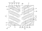
- FIG. 1A is a perspective view of a rubber crawler according to an embodiment of the present invention, viewed from the grounding surface side, showing a part cut in the crawler circumferential direction.
- FIG. 1B is a plan view of a rubber crawler according to one embodiment of the present invention, viewed from the grounding surface side, showing a part cut in the crawler circumferential direction.
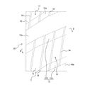
- FIG. 2A is a partially enlarged view showing a part X of FIG. 1B in an enlarged manner.
- 2B is a cross-sectional view taken along line BB in FIG. 2A.
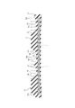
- FIG. 3 is a cross-sectional view taken along line AA in FIG. 1B.
- FIG. 1A is a perspective view of a rubber crawler according to an embodiment of the present invention, viewed from the grounding surface side, showing a part cut in the crawler circumferential direction.
- FIG. 2A is a partially enlarged view showing a part X of FIG. 1B in an enlarged manner.
- the rubber crawler 10 is made of a rubber elastic body having an endless constant width, and a convex lug 11 on the outer peripheral surface (crawler outer peripheral surface) is predetermined in the crawler circumferential direction. It is formed with a pitch.
- the rubber crawler 10 is mounted on a vehicle used for construction / civil engineering work, agricultural work, and the like, and is driven to travel by transmitting a driving force from a driving force generation source provided in the vehicle.
- the lug 11 protrudes from the crawler outer peripheral surface 10a serving as a crawler running surface, and has a vertical wall-shaped peripheral surface 12 that is inclined so as to narrow toward the upper side, and a plan view at the top.
- a crawler circumferential cross section having a ground contact surface (tread surface) 13 formed of a rectangular flat surface is formed in a substantially trapezoidal convex shape (see FIGS. 1A and 1B).
- the lug 11 is inclined at a predetermined angle with respect to the crawler width direction in a plan view, and the crawler width direction central side portion is bent in a direction in which the inclination angle is increased to extend in the crawler width direction. (See FIGS. 1A and 1B).
- the lug 11 has a groove-like space S extending along the crawler circumferential direction in the center of the crawler width direction in plan view over the entire circumference of the crawler outer circumferential surface 10a. A plurality of them are juxtaposed at a predetermined pitch in the crawler circumferential direction so as to be substantially symmetrical with respect to the width of the crawler in the crawler width direction (see FIGS. 1A and 1B).
- the lug 11 is placed on the crawler outer peripheral surface 10a in the reverse direction opposite to the forward direction of the rubber crawler 10 when mounted on the vehicle (the lower direction in FIG. 1A and FIG. 1B). It is arranged in a substantially C-shape that spreads toward the end with a predetermined interval in the crawler circumferential direction (see FIGS. 1A and 1B).
- the direction in which the lugs 11 are arranged is not limited to the generally square shape spreading toward the backward direction of the rubber crawler 10 described above, and the substantially square shape spreading toward the forward direction of the rubber crawler 10 in the opposite direction. But you can.
- the rubber crawler 10 in the present embodiment is a so-called large-sized rubber crawler 10 in which the height of the lug 11 from the crawler outer peripheral surface 10a is 40 mm or more and about 70 mm at the maximum.
- the present invention is particularly preferably applied to such a large rubber crawler of 40 mm or more, more preferably 50 mm or more.
- the peripheral surface 12 faces (faces) in the crawler circumferential direction, and bends in the crawler circumferential direction corresponding to the shape of the ground contact surface 13, the first side surface 12 a and the second side surface 12 b, and the crawler width. It has an inner first end face 12c, an inner second end face 12d, and an outer end face 12e facing (facing) the direction (see FIGS. 1A and 1B).
- the first side surface 12a, the second side surface 12b, the inner first end surface 12c, and the inner second end surface 12d rise from the crawler outer peripheral surface 10a via an inwardly convex curved surface (see FIG. 1A).
- the end surfaces 12e are formed so as to rise directly from the crawler outer peripheral surface 10a, and the inner first end surfaces 12c located on both sides of the groove-shaped space S at the center in the crawler width direction are substantially half in the crawler circumferential direction. Opposite each other with a pitch difference (see FIGS. 1A and 1B).
- the first side surface 12a is the stepping surface of the lug 11
- the second side surface 12b is the kicking surface of the lug 11
- the first side surface 12a which is the stepping surface
- the lug 11 is a cross-sectional view when viewed from the crawler width direction ( In the crawler width direction sectional view)
- the lug 11 has a curved surface shape that protrudes forward in the crawler rotation direction.
- the inner first end face 12c, the inner second end face 12d, and the outer end face 12e are formed as flat surfaces.
- positioning of the lug 11 can be made into arbitrary things.
- the rubber crawler 10 made of a rubber elastic body has a member such as a reinforcing cord made of steel cord embedded therein, but the internal structure of the rubber crawler 10 is It can be arbitrary.
- the crawler is attached to the side faces of the lugs 11 facing the crawler circumferential direction, that is, the first side face 12a and the second side face 12b.
- a plurality of minute protrusions (vent ridges) 14 extending in a direction intersecting the crawler width direction when viewed from the circumferential direction are formed in a row in the crawler width direction (see FIGS. 2A, 2B, and 3). .
- the minute protrusions 14 formed on the first side surface 12a and the second side surface 12b are also continuous with the first side surface 12a and the second side surface 12b on the ground contact surface 13 of the lug 11 in the crawler width direction.
- a plurality of rows are formed side by side (see FIGS. 1A and 1B, FIGS. 2A and 2B, and FIG. 3).
- the lug 11 has a protruding portion from the crawler outer peripheral surface 10a of the lug 11 to the first side surface 12a, the grounding surface 13, and the second side surface 12b in the crawler circumferential direction.
- Convex-shaped micro-projections 14 extending continuously are arranged in a plurality of rows at substantially equal intervals in the crawler width direction (see FIGS. 1A and 1B, FIGS. 2A and 2B, and FIG. 3).
- the minute protrusions 14 are formed so as to protrude from the surfaces of the first side surface 12 a, the ground contact surface 13, and the second side surface 12 b, which are the surfaces of the lugs 11.
- the minute projections 14 formed on the first side surface 12 a and the second side surface 12 b are not necessarily the entire height direction of the peripheral surface 12 from the crawler outer peripheral surface 10 a that is the lowest portion of the lug 11 to the ground contact surface 13 that is the highest portion. However, it is sufficient that there is a component extending at least in the height direction of the peripheral surface 12 when viewed from the crawler circumferential direction.
- a convex curved surface is included on the inner side in contact with the crawler outer peripheral surface 10a. It is formed with. In addition, you may form except the convex curved surface inside the crawler outer peripheral surface 10a.
- minute convex portion 14 may be formed without being continuous with the first side surface 12a, the grounding surface 13 and the second side surface 12b, only the first side surface 12a, only the first side surface 12a and only the grounding surface 13, Only the second side surface 12 b may be formed only on the second side surface 12 b and the grounding surface 13.
- the minute convex part 14 is formed on the minute convex part 14 provided in the molding die when the rubber crawler 10 having the lug 11 on which the minute convex part 14 is formed is formed by vulcanization molding. It can be formed by corresponding recesses.
- the minute convex portion 14 is formed by a concave portion provided in the molding die, it is preferable that the concave portion communicate with an exhaust passage that opens to the outside of the molding die.
- the concave portion forming the minute convex portion 14 is used for venting to discharge the air inside the rubber crawler molding die to the outside of the die at the time of vulcanization molding using the rubber crawler molding die. It can function as a passage.
- the minute convex portion 14 is also formed on the ground surface 13 as in the present embodiment, and further, the first side surface 12a and / or the second side surface 12b. It is desirable that the contact surface 13 is continuously formed.
- the minute protrusions 14 preferably have a width of 0.5 to 3 mm, more preferably 0.7 to 2 mm, and a height of 0.5 to 3 mm.
- the thickness is 0.7 to 1 mm. If the width of the minute convex portion 14 is too narrow, the air venting effect may be reduced, and if it is too wide, the convex portion may be filled with rubber at an early stage and may not function as an air vent. In addition, if the height of the minute protrusions 14 is too high, for example, there is a risk of being caught by a molding die during crawler production and causing scratches, and if it is too low, sufficient effects due to the minute protrusions 14 may not be obtained. is there.
- the minute protrusions 14 formed in a plurality of rows along the crawler width direction on the first side surface 12a, the second side surface 12b, and the ground surface 13 are formed along the crawler circumferential direction. It is not necessarily required to follow the crawler circumferential direction, and is inclined with respect to the crawler circumferential direction (for example, a range of about ⁇ 20 degrees) (see FIGS. 1A and 1B, 2A, 2B, and 3). Also good.
- the minute protrusions 14 are arranged so as to be inclined with respect to the crawler width direction without being parallel to the crawler width direction.
- the distance between the rows of minute protrusions 14 formed in a plurality of rows is preferably 10 to 20 mm, and more preferably 10 to 15 mm. If the distance between the rows of the minute projections 14 is too short, the processing may be difficult, and if it is too long, the air venting effect may be reduced.
- the first side surface 12a and the second side surface 12b of the lug 11 in the present embodiment are not limited to an inclined surface composed of a single flat surface having a single inclination angle with respect to the height direction of the lug 11, and a plurality of flat surfaces It may be a multi-step inclined surface made of or an inclined surface made of an uneven curved surface, or may be a two-step inclined surface including a convex curved surface, for example.
- the lug 11 that extends to the crawler width direction end 10b is an end surface that faces the crawler width direction outer side of the crawler width direction outer end.
- a concave portion 15 that is recessed inward in the crawler width direction is formed on an outer end surface 12e, and the contour line of the concave portion 15 is separated from the contour line of the outer end surface 12e by a predetermined distance. It is formed in a substantially triangular shape (see FIG. 4A). That is, the concave portion 15 is opened in the outer end surface 12e at a predetermined distance from the outline that borders the outer shape of the outer end surface 12e.
- the outer end surface 12e formed with the recess 15 is continuous with the crawler width direction end 10b of the rubber crawler 10 and is upward, that is, in contact with the crawler outer peripheral surface 10a at an angle of, for example, 40 to 80 °. It is formed by an inclined surface inclined toward the ground (tread surface) 13 (see FIG. 4B).
- the outer end surface 12e formed of the inclined surface has an upper bottom along the ground contact surface (treading surface) 13, a lower bottom along the crawler outer peripheral surface 10a, and the first side surface 12a side as viewed from the crawler width direction.
- the second side surface 12b side extends substantially perpendicularly to the outer peripheral surface 10a, and has a substantially trapezoidal shape including legs extending obliquely toward the first side surface 12a side with respect to the crawler outer peripheral surface 10a (see FIG. 4A).
- the substantially triangular shape that is the opening shape of the concave portion 15 has a curved surface shape in which the inner side surface in the crawler width direction is convex toward the inner side in the crawler width direction in this embodiment.
- the concave portion 15 is viewed in a plan view, that is, when viewed from the grounding surface (treading surface) 13 side, the crawler outer peripheral surface 10a side is the bottom surface 15a, and the grounding surface (treading surface) 13 side is the grounding surface.
- (Treading surface) It has a substantially triangular shape, which is a curved top portion 15b having an arcuate cross section that protrudes toward the side 13 (see FIG. 4A). Concentration of stress on the top portion 15b can be avoided by forming the top portion 15b of the concave portion 15 into a curved shape that is convex toward the ground contact surface (treading surface) 13 side.
- the recess 15 has a substantially triangular opening shape, but the lug 11 has a flat shape in accordance with the asymmetric shape having different inclination angles on both sides in the crawler circumferential direction.
- the substantially triangular shape as viewed also has an asymmetric shape with different inclination angles on both sides in the crawler circumferential direction.
- the crawler circumferential length of the bottom surface 15 a of the concave portion 15 having a substantially triangular shape is the length of the lug bottom of the lug 11, and the crawler circumferential contact length with the crawler outer circumferential surface 10 a of the lug 11.
- the crawler circumferential length of the curved portion of the top portion 15b is 0.4 to 0.7 times the crawler circumferential length of the ground contact surface (tread surface) 13 that is the top surface of the lug 11. .1 to 0.3 times.
- the concave portion 15 has a substantially triangular cross section in the crawler width direction, and as an example of a substantially triangular shape, a part of the outer end surface 12e formed of an inclined surface is a bottom surface in the cross section in the crawler width direction.
- the sides along the lug protrusion direction, which is the direction, and the sides along the crawler outer peripheral surface 10a, which are the depth direction, are the hypotenuses (see FIG. 4B).
- the ratio of the length of the side in the depth direction to the length of the side in the height direction of the recess 15 having a substantially triangular cross section in the crawler width direction is 1: 0.8 to 1.2.
- the ratio is 1: 1.
- the angle of the top of the concave portion 15 having a substantially triangular cross section in the crawler width direction is preferably 80 to 100 °, and more preferably 90 °.
- the side in the height direction and the side in the depth direction have a substantially isosceles triangular shape having substantially the same length.
- the recess 15 is not limited to a substantially isosceles triangle shape in which the side in the height direction and the side in the depth direction have substantially the same length in the cross section in the crawler width direction.
- a substantially triangular shape that is longer than the side in the depth direction or a substantially triangular shape in which the side in the height direction is shorter than the side in the depth direction may be used.
- the contour line of the concave portion 15 having a substantially triangular shape on the ground contact surface (tread surface) 13 side is a substantially trapezoidal outer end surface 12e whose shape on the ground contact surface (tread surface) 13 side is the same as the shape seen from the crawler width direction.
- the crawler width direction distance a of the upper end portion of the concave portion 15 is, for example, 3 to 6 mm
- the crawler width direction distance b of the lower end portion of the concave portion 15 is, for example, 3 to 6 mm.
- the distance from 10a is 3 to 6 mm, for example, at a distance c in the lug protrusion direction.
- the recess 15 has a lug protrusion direction distance c of, for example, 3 to 6 mm between the bottom surface of the lug 11, that is, the crawler outer peripheral surface 10 a, and is separated above the crawler outer peripheral surface 10 a (lag protruding direction). (See FIG. 4B).
- the lug 11 is formed by the inclined end surface 12e, which is an end surface facing the outer side in the crawler width direction, of the outer end in the crawler width direction, by an inclined surface continuing to the end 10b in the crawler width direction (see FIG. 4B).
- the crawler 10 is not provided with an edge portion that is an edge portion in the crawler width direction, and the crawler width direction width of the lug 11 can be expanded to the full end 10b of the rubber crawler 10 (FIGS. 1A and 1B, FIG. 4A and 4B), it is possible to improve the durability of the rubber crawler 11 and increase the durability.
- the recess 15 on the outer end surface 12e of the lug 11, even if the crawler width direction width of the lug 11 is widened, it is possible to suppress an increase in the rigidity of the outer end of the lug 11 in the crawler width direction.
- the recess 15 since the recess 15 has the above-described configuration, concentration of stress on the outer end in the crawler width direction of the lug 11 can be prevented, and durability at the outer end in the crawler width direction of the lug 11 can be ensured.
- FIG. 5 is a partial cross-sectional view showing an upper die and a lower die of a rubber crawler molding die according to an embodiment of the present invention.
- the rubber crawler molding die 20 of the present embodiment has an upper mold 21 and a lower mold 22, and is an unvulcanized rubber member positioned between the upper mold 21 and the lower mold 22.
- the rubber crawler molding die 20 is, as an example, the rubber crawler according to the present embodiment described above with reference to FIGS. 1A and 1B, FIGS. 2A and 2B, FIGS. 3, 4A and 4B. 10 will be described for manufacturing.
- the upper die 21 is the first of the lug forming blocks 23 of the upper die 21 that form the lugs 11 protruding from the lug surface L of the unvulcanized rubber member G and facing the crawler circumferential direction of the lugs 11.
- the lug side surface forming portion 23a that forms the first side surface 12a and the second side surface 12b is provided with a concave portion (small concave portion) 24 (see FIG. 5). . Due to the recess 24, the minute projections 14 (see FIGS.
- the recess 24 communicates with an exhaust passage (not shown) that opens to the outside of the rubber crawler molding die 20, and during the vulcanization molding using the rubber crawler molding die 20 of the present embodiment, the rubber crawler. It functions as a vent passage for discharging air from the inside of the molding die 20 to the outside.
- the lug molding block 23 of the upper mold 21 may be integrated as a separate body by bolting or the like. In this case, a minute gap generated when the lug molding block 23 which is a separate body is combined is used as a discharge passage. The air can also be discharged from here.
- the concave portion 24 is formed in the present embodiment, in addition to the lug side surface forming portion 23a, and the lug molding block adjacent to the upper die 21 that forms the ground contact surface 13 of the lug 11 of the rubber crawler 10.
- the lug grounding surface forming portion 23b formed of a groove-like recess between the two is formed in the same manner as the lug side surface forming portion 23a (see FIG. 5).
- the recess 24 formed in the lug ground contact surface forming portion 23b is formed integrally with the recess 24 formed in the lug side surface forming portion 23a (see FIG. 5). It communicates with an exhaust passage (not shown) that opens to the outside of the crawler mold 20.
- the recess 24 may be formed without communicating with the lug side surface forming portion 23a and the lug ground surface forming portion 23b, or only the lug side surface forming portion 23a is the lug side surface forming portion 23a and the lug ground surface forming portion 23b. However, it may be formed only on the lug ground plane forming portion 23b, but from the viewpoint of further enhancing the effect of air vent described later, it is also formed on the lug ground plane forming portion 23b as in the present embodiment. Furthermore, it is desirable that the lug side surface forming portion 23a and the lug ground surface forming portion 23b are formed continuously.
- the lug molding block 23 gradually enters the unvulcanized rubber member G placed on the lower die 22 from the tip, and accordingly, the upper die
- the air between the upper die 21 and the unvulcanized rubber member G passes through the recess 24 formed in the lug side surface forming portion 23 a of the lug molding block 23, and is above the lug molding block 23. And move. That is, in this embodiment, the air inside the mold 20 is between the unvulcanized rubber member G and the lug side surface forming portion 23a of the lug molding block 23 that is in close contact with the unvulcanized rubber member G. , And moves up through the space formed by the recess 24.
- the pressing of the unvulcanized rubber member G on the upper die 21 proceeds, and the lug contact of the upper die 21 is brought into contact with the unground rubber member G at the lug ground contact surface forming portion 23b of the upper die 21.
- the air inside the mold 20 that has risen toward the ground forming portion 23b communicates with and integrated with the concave portion 24 formed in the lug side surface forming portion 23a, and is formed in the concave portion 24 ( (See FIG. 5).
- the air enters and passes through an exhaust passage (not shown) that opens to the outside of the rubber crawler molding die 20, and is discharged to the outside of the rubber crawler molding die 20.
- the lug ground contact surface forming portion 23b of the upper die 21 comes into close contact with the unvulcanized rubber member G, and the unvulcanized rubber member G is vulcanized and molded, so that the rubber crawler 10 is obtained.
- the unvulcanized rubber member G that has entered the recess 24 formed in the lug side surface forming portion 23a causes the first side surface 12a of the lug 11 and the first side surface 12a.
- the minute projections 14 are formed on the two side surfaces 12 b, and the minute projections 14 are formed on the ground contact surface 13 of the lug 11 by the unvulcanized rubber member G that has entered the recess 24 of the lug contact surface formation portion 23 b.
- the concave portion 24 formed in the lug side surface forming portion 23a together with the concave portion 24 formed in the lug ground surface forming portion 23b, causes the air inside the rubber crawler molding die 20 to be discharged to the outside during vulcanization molding. It becomes a vent passage to be discharged.
- the upper mold 21 and the lower mold 22 can be kept at a high temperature as necessary.
- the air inside the die 20 is Through the recess 24 formed in the lug side surface forming portion 23a and the lug grounding surface forming portion 23b of the upper mold 21, the mold 20 (upper mold 21) is not retained inside the mold 20 (upper mold 21). Active escape from inside to outside.
- the height from the crawler outer peripheral surface 10a of the lug 11 to the ground contact surface (top surface) 13 is 40 mm or more, particularly 50 mm or more.
- air in the mold 20 can be surely released during vulcanization molding. This is because the protrusion height of the lug 11 is increased and the distance to the top surface portion of the lug is increased, and the air moving distance on the first side surface 12a and the second side surface 12b of the lug 11 is increased during vulcanization molding. This is also because the flow path for air movement can be secured by the recess 24 formed in the lug side surface forming portion 23a.
- the rubber crawler 10 when the rubber crawler 10 is manufactured by vulcanization molding using the die 20, the molding is performed. Since it is possible to suppress the occurrence of defects, it is possible to reduce the appearance defects caused by the molding defects. In the case of a large-sized rubber crawler 10 of a certain size, the number of occurrences of molding failure and unit appearance failure per unit is increased by the mold 20 in which the recess 24 is provided only in the lug ground contact surface forming portion 23b. Compared with the conventional product in which the minute convex portion 14 is formed only on the ground contact surface 13 of the lug 11, the thickness is reduced to about 1/3.
- the minute protrusions 14 are formed on the side surfaces of the lugs 11, so that it is possible to improve mud separation and traction when the rubber crawler 10 is traveling.
- the rubber crawler 10 of the present invention can be suitably manufactured by the rubber crawler manufacturing method of the present invention using the rubber crawler molding die 20 of the present invention.
- 10 rubber crawler
- 10a crawler outer peripheral surface
- 11 lug
- 12 peripheral surface
- 12a first side surface
- 12b second side surface
- 12c inner first end surface
- 12d inner second end surface
- 12e outer end surface
- 13 ground contact surface
- 14 minute convex portion
- 15a bottom surface
- 15b top portion
- 20 rubber crawler molding die
- 21 upper die
- 22 lower die
- 23a Lug side surface forming portion
- 23b lug ground contact surface forming portion
- 24 concave portion
- S grooved space
- G unvulcanized rubber member
- L lug surface.
Landscapes
- Engineering & Computer Science (AREA)
- Mechanical Engineering (AREA)
- Chemical & Material Sciences (AREA)
- Combustion & Propulsion (AREA)
- Transportation (AREA)
- Heating, Cooling, Or Curing Plastics Or The Like In General (AREA)
- Moulds For Moulding Plastics Or The Like (AREA)
- Casting Or Compression Moulding Of Plastics Or The Like (AREA)
Abstract
Description
ゴムクローラは、例えば、金型の上型と下型の間に位置させた未加硫ゴム部材を、上型でプレスしラグ面を加硫成形して形成されるが、ラグ形状が複雑な場合、成形時に、所謂エア噛みと呼ばれる、金型内の空気が抜けないことによる成形不良が発生し易い。
そこで、この発明の目的は、加硫成形時に金型内から確実に空気を抜くことができ、空気が抜けないことによって生じる成形不良を抑制することができる、ゴムクローラ、ゴムクローラ成形金型、及びゴムクローラの製造方法を提供することである。
図1Aは、この発明の一実施の形態に係るゴムクローラの、クローラ周方向で切断した一部を示す、接地面側から見た斜視図である。図1Bは、この発明の一実施の形態に係るゴムクローラの、クローラ周方向で切断した一部を示す、接地面側から見た平面図である。図2Aは、図1Bの一部Xを拡大して示す、部分拡大図である。図2Bは、図2AのB-B線に沿う断面図である。図3は、図1BのA-A線に沿う断面図である。図4Aは、図1Bの一部Yを拡大して示す、部分拡大図である。図4Bは、図1Bの一部Yを拡大して示す、図4AのA-A線に沿う断面図である。
図1A及び図1Bに示すように、本実施形態のゴムクローラ10は、無端状一定幅のゴム弾性体からなり、外周面(クローラ外周面)に凸状のラグ11がクローラ周方向に所定のピッチで形成されている。このゴムクローラ10は、建築・土木作業や農作業等に用いる車両に装着され、車両に備えられた駆動力発生源から駆動力が伝達されることで走行駆動される。
また、ラグ11は、本実施形態において、クローラ外周面10aのクローラ周方向全周に亘り、平面視で、クローラ幅方向中央のクローラ周方向に沿って延びる溝状空間Sを境に、クローラ周方向に略半ピッチ分ずらして両側に振り分けられ、クローラ幅方向左右略対称形となるように、クローラ周方向に所定ピッチで複数並置されている(図1A及び図1B参照)。
本発明は、このような40mm以上、より好ましくは50mm以上の大型のゴムクローラに適用するのが特に好ましい。
周面12は、本実施形態において、クローラ周方向に向いて(面して)おり、接地面13の形状に対応してクローラ周方向に屈曲する第1側面12aと第2側面12b、クローラ幅方向に向いて(面して)いる内側第1端面12cと内側第2端面12d、及び外側端面12eを有している(図1A及び図1B参照)。
なお、ラグ11の形状や配置は、本発明の目的が達成される限り、任意のものとすることができる。
また、本実施形態において、ゴム弾性体からなるゴムクローラ10は、その内部に、例えばスチールコードからなる補強コード等の部材が埋め込まれているものであるが、ゴムクローラ10の内部構造等は、任意のものとすることができる。
複数列形成される微小凸部14の列間距離は、本実施形態において、10~20mmとすることが好ましく、10~15mmとすることが更に好ましい。微小凸部14の列間距離が短すぎると加工が困難になる虞があり、長すぎると空気抜きの効果が低下する虞がある。
この傾斜面からなる外側端面12eは、本実施形態において、接地面(踏面)13に沿う上底、クローラ外周面10aに沿う下底、及びクローラ幅方向から見て、第1側面12a側が、クローラ外周面10aに対し略垂直に延在し、第2側面12b側が、クローラ外周面10aに対し第1側面12a側に傾斜して延在する脚、からなる略台形状を有している(図4A参照)。
本実施形態において、略三角形状を有する凹部15の、底面15aのクローラ周方向長さは、ラグ11のラグ底長さである、ラグ11のクローラ外周面10aとのクローラ周方向接触長さの、例えば、0.4~0.7倍とし、頂部15bの曲面部分のクローラ周方向長さは、ラグ11の頂面である接地面(踏面)13のクローラ周方向長さの、例えば、0.1~0.3倍としている。
本実施形態において、クローラ幅方向断面が略三角形状の凹部15の、高さ方向の辺の長さに対する奥行き方向の辺の長さの比は、1対0.8~1.2であることが好ましく、1対1であることが更に好ましい。また、クローラ幅方向断面が略三角形状の凹部15の頂部の角度は、80~100°であることが好ましく、90°であることが更に好ましい。
なお、凹部15は、クローラ幅方向断面において、高さ方向の辺と奥行き方向の辺が略同一長さの略二等辺三角形状とすることに限るものではなく、高さ方向の辺の方が奥行き方向の辺より長い略三角形状、或いは高さ方向の辺の方が奥行き方向の辺より短い略三角形状としても良い。
つまり、凹部15は、ラグ11の底面、即ち、クローラ外周面10aとの間に、例えば3~6mmのラグ突出方向距離cを有して、クローラ外周面10aの上方(ラグ突出方向)に離間して配置されている(図4B参照)。
この結果、ラグ11のクローラ外周面10aからの高さが40mm以上、特に、50mm以上の大型のゴムクローラにおいて、走行路面上での車両旋回時に、ラグがゴムクローラの路面側に巻き込まれてしまって、ゴムクローラ内部に埋め込まれているスチールコードの近傍でゴム歪が増加したために、ラグに割れが発生してしまうことを、極力抑制することができ、ひいては外観不良の発生を抑制することができる。
図5に示すように、本実施形態のゴムクローラ成形金型20は、上型21と下型22とを有し、上型21と下型22との間に位置させた未加硫ゴム部材Gと上型21とを相対的にプレス(本実施形態では、未加硫ゴム部材Gを上型21でプレス)し、ラグ面Lを加硫成形することにより、ゴムクローラ10を得るために用いられるものである。
なお、以下の説明において、ゴムクローラ成形金型20は、一例として、図1A及び図1B、図2A及び図2B、図3、図4A及び図4Bを用いて前述した本実施形態に係るゴムクローラ10を製造するためのものとして説明する。
また、この凹部24は、ゴムクローラ成形金型20の外部に開口する排気通路(図示しない)に連通しており、本実施形態のゴムクローラ成形金型20を用いた加硫成形時に、ゴムクローラ成形金型20の内部から外部へ空気を排出するベント用通路として機能する。
上型21のラグ成形ブロック23は、別体として、ボルト止め等で一体化してあっても良く、この場合、別体であるラグ成形ブロック23を組み合わせた際に生じる微小な隙間を排出通路として、ここからも空気を排出することができる。
本実施形態において、無端状のゴム弾性体からなり、外周面に凸状のラグがクローラ周方向に所定のピッチで形成されたゴムクローラを得るために、ゴムクローラを製造する際、この発明に係るゴムクローラ成形金型20の、上型21と下型22との間に位置させたラグ面を有する未加硫ゴム部材Gと上型21とを相対的にプレス(本実施形態では、未加硫ゴム部材Gを上型21でプレス)し、ラグ面を加硫成形することにより、ゴムクローラ10を得る。
つまり、本実施形態において、金型20の内部の空気は、未加硫ゴム部材Gと、当該未加硫ゴム部材Gと密着状態にあるラグ成形ブロック23のラグ側面形成部23aとの間で、凹部24により形成された空間を通り抜け上昇移動する。
本発明のゴムクローラ10は、本発明のゴムクローラ成形金型20を用いた、本発明のゴムクローラの製造方法によって、好適に製造することができる。
Claims (6)
- 無端状のゴム弾性体からなり、外周面に凸状のラグがクローラ周方向に所定のピッチで形成されたゴムクローラであって、
前記ラグのクローラ周方向を向く側面に、クローラ周方向から見た場合にクローラ幅方向と交差する方向に延びる、微小凸部が形成されていることを特徴とする、ゴムクローラ。 - 前記ラグの接地面に、微小凸部が形成されている、請求項1に記載のゴムクローラ。
- 前記ラグの側面の微小凸部と前記ラグの接地面の微小凸部とが、連続して形成されている、請求項2に記載のゴムクローラ。
- 上型と下型とを有し、前記上型と前記下型との間に位置させたラグ面を有する未加硫ゴム部材と前記上型とを相対的にプレスし、前記ラグ面を加硫成形することにより、ゴムクローラを得る、ゴムクローラ成形金型であって、
前記ラグ面に突設されるラグを形成する、前記上型のラグ成形ブロックの、前記ラグのクローラ周方向を向く側面を形成するラグ側面形成部に、微小凹部が設けられていることを特徴とする、ゴムクローラ成形金型。 - 前記ラグの接地面を形成するラグ接地面形成部に、微小凹部が設けられている、請求項4に記載のゴムクローラ成形金型。
- 無端状のゴム弾性体からなり、外周面に凸状のラグがクローラ周方向に所定のピッチで形成されたゴムクローラを得るための、ゴムクローラの製造方法であって、
請求項4又は5に記載のゴムクローラ成形金型の、前記上型と前記下型との間に位置させたラグ面を有する未加硫ゴム部材と前記上型とを相対的にプレスし、前記ラグ面を加硫成形することにより、前記ゴムクローラを得ることを特徴とする、ゴムクローラの製造方法。
Priority Applications (4)
| Application Number | Priority Date | Filing Date | Title |
|---|---|---|---|
| CN201880007100.3A CN110177734A (zh) | 2017-01-20 | 2018-01-19 | 橡胶履带、橡胶履带模具和制造橡胶履带的方法 |
| JP2018562465A JPWO2018135643A1 (ja) | 2017-01-20 | 2018-01-19 | ゴムクローラ、ゴムクローラ成形金型、及びゴムクローラの製造方法 |
| US16/475,450 US20190344842A1 (en) | 2017-01-20 | 2018-01-19 | Rubber crawler, rubber crawler mold, and method of producing rubber crawler |
| CA3051070A CA3051070A1 (en) | 2017-01-20 | 2018-01-19 | Rubber crawler, rubber crawler mold, and method of producing rubber crawler |
Applications Claiming Priority (2)
| Application Number | Priority Date | Filing Date | Title |
|---|---|---|---|
| JP2017-008914 | 2017-01-20 | ||
| JP2017008914 | 2017-01-20 |
Publications (1)
| Publication Number | Publication Date |
|---|---|
| WO2018135643A1 true WO2018135643A1 (ja) | 2018-07-26 |
Family
ID=62908143
Family Applications (1)
| Application Number | Title | Priority Date | Filing Date |
|---|---|---|---|
| PCT/JP2018/001661 Ceased WO2018135643A1 (ja) | 2017-01-20 | 2018-01-19 | ゴムクローラ、ゴムクローラ成形金型、及びゴムクローラの製造方法 |
Country Status (5)
| Country | Link |
|---|---|
| US (1) | US20190344842A1 (ja) |
| JP (1) | JPWO2018135643A1 (ja) |
| CN (1) | CN110177734A (ja) |
| CA (1) | CA3051070A1 (ja) |
| WO (1) | WO2018135643A1 (ja) |
Families Citing this family (3)
| Publication number | Priority date | Publication date | Assignee | Title |
|---|---|---|---|---|
| US20230042085A1 (en) * | 2020-01-22 | 2023-02-09 | Camso Inc. | Track system for traction of a vehicle |
| EP4601935A4 (en) * | 2022-10-12 | 2026-02-18 | Camso Inc | TRACK WITH IRREGULAR EDGES FOR VEHICLE TOWING |
| WO2026064842A1 (en) * | 2024-09-26 | 2026-04-02 | "Medina Med" Limited Liability Company | Expandable die for worn rubber chains regenerating |
Citations (3)
| Publication number | Priority date | Publication date | Assignee | Title |
|---|---|---|---|---|
| JPS5123784B2 (ja) * | 1971-03-26 | 1976-07-19 | ||
| JPH034366B2 (ja) * | 1981-03-18 | 1991-01-22 | Bridgestone Corp | |
| JP2011195085A (ja) * | 2010-03-23 | 2011-10-06 | Sumitomo Rubber Ind Ltd | 芯金レスの弾性クローラ |
Family Cites Families (4)
| Publication number | Priority date | Publication date | Assignee | Title |
|---|---|---|---|---|
| JP5123784B2 (ja) * | 2008-08-12 | 2013-01-23 | 千代田工営株式会社 | マンホール浮上抑制装置 |
| KR101395422B1 (ko) * | 2009-09-16 | 2014-05-14 | 가부시키가이샤 브리지스톤 | 고무 크롤러 |
| JP2014015156A (ja) * | 2012-07-10 | 2014-01-30 | Bridgestone Corp | ゴムクローラ |
| JP5851546B2 (ja) * | 2014-04-14 | 2016-02-03 | 株式会社ブリヂストン | クローラ |
-
2018
- 2018-01-19 CA CA3051070A patent/CA3051070A1/en not_active Abandoned
- 2018-01-19 JP JP2018562465A patent/JPWO2018135643A1/ja active Pending
- 2018-01-19 CN CN201880007100.3A patent/CN110177734A/zh active Pending
- 2018-01-19 US US16/475,450 patent/US20190344842A1/en not_active Abandoned
- 2018-01-19 WO PCT/JP2018/001661 patent/WO2018135643A1/ja not_active Ceased
Patent Citations (3)
| Publication number | Priority date | Publication date | Assignee | Title |
|---|---|---|---|---|
| JPS5123784B2 (ja) * | 1971-03-26 | 1976-07-19 | ||
| JPH034366B2 (ja) * | 1981-03-18 | 1991-01-22 | Bridgestone Corp | |
| JP2011195085A (ja) * | 2010-03-23 | 2011-10-06 | Sumitomo Rubber Ind Ltd | 芯金レスの弾性クローラ |
Also Published As
| Publication number | Publication date |
|---|---|
| JPWO2018135643A1 (ja) | 2019-11-07 |
| CN110177734A (zh) | 2019-08-27 |
| US20190344842A1 (en) | 2019-11-14 |
| CA3051070A1 (en) | 2018-07-26 |
Similar Documents
| Publication | Publication Date | Title |
|---|---|---|
| JP5011880B2 (ja) | 空気入りタイヤ | |
| US10252575B2 (en) | Pneumatic tire | |
| JP6826432B2 (ja) | タイヤ加硫金型および空気入りタイヤ | |
| US9764600B2 (en) | Pneumatic tire for vehicle | |
| CN1250413A (zh) | 胎面花纹及其制造方法 | |
| WO2010039148A1 (en) | Undulated progressive tire mold element | |
| JP6449005B2 (ja) | 空気入りタイヤ | |
| WO2018135643A1 (ja) | ゴムクローラ、ゴムクローラ成形金型、及びゴムクローラの製造方法 | |
| US6443200B1 (en) | Tread including relief elements having undercut lateral walls and incision that does not cut into ridge | |
| KR20140065816A (ko) | 공기입 타이어 | |
| KR101917494B1 (ko) | 타이어 가류금형의 커프 성형용 블레이드와 이를 이용한 차량용 타이어 및 타이어 가류장치 | |
| CN109262908B (zh) | 轮胎硫化模具 | |
| JP5403985B2 (ja) | 空気入りタイヤ | |
| JPH01175507A (ja) | 空気入りタイヤ | |
| JP5575560B2 (ja) | 空気入りタイヤ | |
| US10399389B2 (en) | Pneumatic tire | |
| JP3992217B2 (ja) | スリックタイヤ | |
| KR101900573B1 (ko) | 타이어 가류금형의 커프 성형용 블레이드, 이를 이용하여 제조되는 차량용 타이어 및 타이어 가류장치 | |
| KR100808297B1 (ko) | 스노우 타이어 | |
| JP5860949B2 (ja) | タイヤ成型用金型およびタイヤ | |
| JP6758206B2 (ja) | ゴムクローラ | |
| KR101995794B1 (ko) | 웨이브형 그루브를 구비한 중하중용 공기입 타이어 | |
| JP2005271644A (ja) | 空気入りタイヤ | |
| JPS6241030A (ja) | タイヤの製造方法 | |
| JPH0966709A (ja) | ブロック・パターンを備えた空気入りタイヤ |
Legal Events
| Date | Code | Title | Description |
|---|---|---|---|
| 121 | Ep: the epo has been informed by wipo that ep was designated in this application |
Ref document number: 18741802 Country of ref document: EP Kind code of ref document: A1 |
|
| ENP | Entry into the national phase |
Ref document number: 2018562465 Country of ref document: JP Kind code of ref document: A |
|
| ENP | Entry into the national phase |
Ref document number: 3051070 Country of ref document: CA |
|
| NENP | Non-entry into the national phase |
Ref country code: DE |
|
| 122 | Ep: pct application non-entry in european phase |
Ref document number: 18741802 Country of ref document: EP Kind code of ref document: A1 |