WO2018131651A1 - Bloc-batterie et système d'énergie - Google Patents
Bloc-batterie et système d'énergie Download PDFInfo
- Publication number
- WO2018131651A1 WO2018131651A1 PCT/JP2018/000496 JP2018000496W WO2018131651A1 WO 2018131651 A1 WO2018131651 A1 WO 2018131651A1 JP 2018000496 W JP2018000496 W JP 2018000496W WO 2018131651 A1 WO2018131651 A1 WO 2018131651A1
- Authority
- WO
- WIPO (PCT)
- Prior art keywords
- charge
- secondary battery
- battery pack
- calculation unit
- state
- Prior art date
Links
Images


Classifications
-
- B—PERFORMING OPERATIONS; TRANSPORTING
- B60—VEHICLES IN GENERAL
- B60L—PROPULSION OF ELECTRICALLY-PROPELLED VEHICLES; SUPPLYING ELECTRIC POWER FOR AUXILIARY EQUIPMENT OF ELECTRICALLY-PROPELLED VEHICLES; ELECTRODYNAMIC BRAKE SYSTEMS FOR VEHICLES IN GENERAL; MAGNETIC SUSPENSION OR LEVITATION FOR VEHICLES; MONITORING OPERATING VARIABLES OF ELECTRICALLY-PROPELLED VEHICLES; ELECTRIC SAFETY DEVICES FOR ELECTRICALLY-PROPELLED VEHICLES
- B60L58/00—Methods or circuit arrangements for monitoring or controlling batteries or fuel cells, specially adapted for electric vehicles
- B60L58/10—Methods or circuit arrangements for monitoring or controlling batteries or fuel cells, specially adapted for electric vehicles for monitoring or controlling batteries
- B60L58/12—Methods or circuit arrangements for monitoring or controlling batteries or fuel cells, specially adapted for electric vehicles for monitoring or controlling batteries responding to state of charge [SoC]
- B60L58/13—Maintaining the SoC within a determined range
-
- B—PERFORMING OPERATIONS; TRANSPORTING
- B60—VEHICLES IN GENERAL
- B60L—PROPULSION OF ELECTRICALLY-PROPELLED VEHICLES; SUPPLYING ELECTRIC POWER FOR AUXILIARY EQUIPMENT OF ELECTRICALLY-PROPELLED VEHICLES; ELECTRODYNAMIC BRAKE SYSTEMS FOR VEHICLES IN GENERAL; MAGNETIC SUSPENSION OR LEVITATION FOR VEHICLES; MONITORING OPERATING VARIABLES OF ELECTRICALLY-PROPELLED VEHICLES; ELECTRIC SAFETY DEVICES FOR ELECTRICALLY-PROPELLED VEHICLES
- B60L58/00—Methods or circuit arrangements for monitoring or controlling batteries or fuel cells, specially adapted for electric vehicles
- B60L58/10—Methods or circuit arrangements for monitoring or controlling batteries or fuel cells, specially adapted for electric vehicles for monitoring or controlling batteries
- B60L58/12—Methods or circuit arrangements for monitoring or controlling batteries or fuel cells, specially adapted for electric vehicles for monitoring or controlling batteries responding to state of charge [SoC]
- B60L58/14—Preventing excessive discharging
-
- B—PERFORMING OPERATIONS; TRANSPORTING
- B60—VEHICLES IN GENERAL
- B60L—PROPULSION OF ELECTRICALLY-PROPELLED VEHICLES; SUPPLYING ELECTRIC POWER FOR AUXILIARY EQUIPMENT OF ELECTRICALLY-PROPELLED VEHICLES; ELECTRODYNAMIC BRAKE SYSTEMS FOR VEHICLES IN GENERAL; MAGNETIC SUSPENSION OR LEVITATION FOR VEHICLES; MONITORING OPERATING VARIABLES OF ELECTRICALLY-PROPELLED VEHICLES; ELECTRIC SAFETY DEVICES FOR ELECTRICALLY-PROPELLED VEHICLES
- B60L58/00—Methods or circuit arrangements for monitoring or controlling batteries or fuel cells, specially adapted for electric vehicles
- B60L58/10—Methods or circuit arrangements for monitoring or controlling batteries or fuel cells, specially adapted for electric vehicles for monitoring or controlling batteries
- B60L58/12—Methods or circuit arrangements for monitoring or controlling batteries or fuel cells, specially adapted for electric vehicles for monitoring or controlling batteries responding to state of charge [SoC]
- B60L58/15—Preventing overcharging
-
- G—PHYSICS
- G01—MEASURING; TESTING
- G01R—MEASURING ELECTRIC VARIABLES; MEASURING MAGNETIC VARIABLES
- G01R31/00—Arrangements for testing electric properties; Arrangements for locating electric faults; Arrangements for electrical testing characterised by what is being tested not provided for elsewhere
- G01R31/36—Arrangements for testing, measuring or monitoring the electrical condition of accumulators or electric batteries, e.g. capacity or state of charge [SoC]
- G01R31/382—Arrangements for monitoring battery or accumulator variables, e.g. SoC
-
- H—ELECTRICITY
- H01—ELECTRIC ELEMENTS
- H01M—PROCESSES OR MEANS, e.g. BATTERIES, FOR THE DIRECT CONVERSION OF CHEMICAL ENERGY INTO ELECTRICAL ENERGY
- H01M10/00—Secondary cells; Manufacture thereof
- H01M10/42—Methods or arrangements for servicing or maintenance of secondary cells or secondary half-cells
- H01M10/425—Structural combination with electronic components, e.g. electronic circuits integrated to the outside of the casing
-
- H—ELECTRICITY
- H01—ELECTRIC ELEMENTS
- H01M—PROCESSES OR MEANS, e.g. BATTERIES, FOR THE DIRECT CONVERSION OF CHEMICAL ENERGY INTO ELECTRICAL ENERGY
- H01M10/00—Secondary cells; Manufacture thereof
- H01M10/42—Methods or arrangements for servicing or maintenance of secondary cells or secondary half-cells
- H01M10/44—Methods for charging or discharging
- H01M10/441—Methods for charging or discharging for several batteries or cells simultaneously or sequentially
-
- H—ELECTRICITY
- H01—ELECTRIC ELEMENTS
- H01M—PROCESSES OR MEANS, e.g. BATTERIES, FOR THE DIRECT CONVERSION OF CHEMICAL ENERGY INTO ELECTRICAL ENERGY
- H01M10/00—Secondary cells; Manufacture thereof
- H01M10/42—Methods or arrangements for servicing or maintenance of secondary cells or secondary half-cells
- H01M10/48—Accumulators combined with arrangements for measuring, testing or indicating the condition of cells, e.g. the level or density of the electrolyte
- H01M10/482—Accumulators combined with arrangements for measuring, testing or indicating the condition of cells, e.g. the level or density of the electrolyte for several batteries or cells simultaneously or sequentially
-
- H—ELECTRICITY
- H01—ELECTRIC ELEMENTS
- H01M—PROCESSES OR MEANS, e.g. BATTERIES, FOR THE DIRECT CONVERSION OF CHEMICAL ENERGY INTO ELECTRICAL ENERGY
- H01M50/00—Constructional details or processes of manufacture of the non-active parts of electrochemical cells other than fuel cells, e.g. hybrid cells
- H01M50/20—Mountings; Secondary casings or frames; Racks, modules or packs; Suspension devices; Shock absorbers; Transport or carrying devices; Holders
- H01M50/202—Casings or frames around the primary casing of a single cell or a single battery
-
- H—ELECTRICITY
- H02—GENERATION; CONVERSION OR DISTRIBUTION OF ELECTRIC POWER
- H02J—CIRCUIT ARRANGEMENTS OR SYSTEMS FOR SUPPLYING OR DISTRIBUTING ELECTRIC POWER; SYSTEMS FOR STORING ELECTRIC ENERGY
- H02J7/00—Circuit arrangements for charging or depolarising batteries or for supplying loads from batteries
- H02J7/0013—Circuit arrangements for charging or depolarising batteries or for supplying loads from batteries acting upon several batteries simultaneously or sequentially
-
- H—ELECTRICITY
- H02—GENERATION; CONVERSION OR DISTRIBUTION OF ELECTRIC POWER
- H02J—CIRCUIT ARRANGEMENTS OR SYSTEMS FOR SUPPLYING OR DISTRIBUTING ELECTRIC POWER; SYSTEMS FOR STORING ELECTRIC ENERGY
- H02J7/00—Circuit arrangements for charging or depolarising batteries or for supplying loads from batteries
- H02J7/0047—Circuit arrangements for charging or depolarising batteries or for supplying loads from batteries with monitoring or indicating devices or circuits
- H02J7/0048—Detection of remaining charge capacity or state of charge [SOC]
- H02J7/0049—Detection of fully charged condition
-
- H—ELECTRICITY
- H02—GENERATION; CONVERSION OR DISTRIBUTION OF ELECTRIC POWER
- H02J—CIRCUIT ARRANGEMENTS OR SYSTEMS FOR SUPPLYING OR DISTRIBUTING ELECTRIC POWER; SYSTEMS FOR STORING ELECTRIC ENERGY
- H02J7/00—Circuit arrangements for charging or depolarising batteries or for supplying loads from batteries
- H02J7/0047—Circuit arrangements for charging or depolarising batteries or for supplying loads from batteries with monitoring or indicating devices or circuits
- H02J7/005—Detection of state of health [SOH]
-
- H—ELECTRICITY
- H02—GENERATION; CONVERSION OR DISTRIBUTION OF ELECTRIC POWER
- H02J—CIRCUIT ARRANGEMENTS OR SYSTEMS FOR SUPPLYING OR DISTRIBUTING ELECTRIC POWER; SYSTEMS FOR STORING ELECTRIC ENERGY
- H02J7/00—Circuit arrangements for charging or depolarising batteries or for supplying loads from batteries
- H02J7/14—Circuit arrangements for charging or depolarising batteries or for supplying loads from batteries for charging batteries from dynamo-electric generators driven at varying speed, e.g. on vehicle
- H02J7/1423—Circuit arrangements for charging or depolarising batteries or for supplying loads from batteries for charging batteries from dynamo-electric generators driven at varying speed, e.g. on vehicle with multiple batteries
-
- B—PERFORMING OPERATIONS; TRANSPORTING
- B60—VEHICLES IN GENERAL
- B60L—PROPULSION OF ELECTRICALLY-PROPELLED VEHICLES; SUPPLYING ELECTRIC POWER FOR AUXILIARY EQUIPMENT OF ELECTRICALLY-PROPELLED VEHICLES; ELECTRODYNAMIC BRAKE SYSTEMS FOR VEHICLES IN GENERAL; MAGNETIC SUSPENSION OR LEVITATION FOR VEHICLES; MONITORING OPERATING VARIABLES OF ELECTRICALLY-PROPELLED VEHICLES; ELECTRIC SAFETY DEVICES FOR ELECTRICALLY-PROPELLED VEHICLES
- B60L2240/00—Control parameters of input or output; Target parameters
- B60L2240/40—Drive Train control parameters
- B60L2240/54—Drive Train control parameters related to batteries
- B60L2240/547—Voltage
-
- B—PERFORMING OPERATIONS; TRANSPORTING
- B60—VEHICLES IN GENERAL
- B60L—PROPULSION OF ELECTRICALLY-PROPELLED VEHICLES; SUPPLYING ELECTRIC POWER FOR AUXILIARY EQUIPMENT OF ELECTRICALLY-PROPELLED VEHICLES; ELECTRODYNAMIC BRAKE SYSTEMS FOR VEHICLES IN GENERAL; MAGNETIC SUSPENSION OR LEVITATION FOR VEHICLES; MONITORING OPERATING VARIABLES OF ELECTRICALLY-PROPELLED VEHICLES; ELECTRIC SAFETY DEVICES FOR ELECTRICALLY-PROPELLED VEHICLES
- B60L2240/00—Control parameters of input or output; Target parameters
- B60L2240/40—Drive Train control parameters
- B60L2240/54—Drive Train control parameters related to batteries
- B60L2240/549—Current
-
- B—PERFORMING OPERATIONS; TRANSPORTING
- B60—VEHICLES IN GENERAL
- B60L—PROPULSION OF ELECTRICALLY-PROPELLED VEHICLES; SUPPLYING ELECTRIC POWER FOR AUXILIARY EQUIPMENT OF ELECTRICALLY-PROPELLED VEHICLES; ELECTRODYNAMIC BRAKE SYSTEMS FOR VEHICLES IN GENERAL; MAGNETIC SUSPENSION OR LEVITATION FOR VEHICLES; MONITORING OPERATING VARIABLES OF ELECTRICALLY-PROPELLED VEHICLES; ELECTRIC SAFETY DEVICES FOR ELECTRICALLY-PROPELLED VEHICLES
- B60L2240/00—Control parameters of input or output; Target parameters
- B60L2240/80—Time limits
-
- G—PHYSICS
- G01—MEASURING; TESTING
- G01R—MEASURING ELECTRIC VARIABLES; MEASURING MAGNETIC VARIABLES
- G01R31/00—Arrangements for testing electric properties; Arrangements for locating electric faults; Arrangements for electrical testing characterised by what is being tested not provided for elsewhere
- G01R31/36—Arrangements for testing, measuring or monitoring the electrical condition of accumulators or electric batteries, e.g. capacity or state of charge [SoC]
- G01R31/382—Arrangements for monitoring battery or accumulator variables, e.g. SoC
- G01R31/3828—Arrangements for monitoring battery or accumulator variables, e.g. SoC using current integration
-
- G—PHYSICS
- G01—MEASURING; TESTING
- G01R—MEASURING ELECTRIC VARIABLES; MEASURING MAGNETIC VARIABLES
- G01R31/00—Arrangements for testing electric properties; Arrangements for locating electric faults; Arrangements for electrical testing characterised by what is being tested not provided for elsewhere
- G01R31/36—Arrangements for testing, measuring or monitoring the electrical condition of accumulators or electric batteries, e.g. capacity or state of charge [SoC]
- G01R31/382—Arrangements for monitoring battery or accumulator variables, e.g. SoC
- G01R31/3842—Arrangements for monitoring battery or accumulator variables, e.g. SoC combining voltage and current measurements
-
- H—ELECTRICITY
- H01—ELECTRIC ELEMENTS
- H01M—PROCESSES OR MEANS, e.g. BATTERIES, FOR THE DIRECT CONVERSION OF CHEMICAL ENERGY INTO ELECTRICAL ENERGY
- H01M10/00—Secondary cells; Manufacture thereof
- H01M10/42—Methods or arrangements for servicing or maintenance of secondary cells or secondary half-cells
- H01M10/425—Structural combination with electronic components, e.g. electronic circuits integrated to the outside of the casing
- H01M2010/4271—Battery management systems including electronic circuits, e.g. control of current or voltage to keep battery in healthy state, cell balancing
-
- Y—GENERAL TAGGING OF NEW TECHNOLOGICAL DEVELOPMENTS; GENERAL TAGGING OF CROSS-SECTIONAL TECHNOLOGIES SPANNING OVER SEVERAL SECTIONS OF THE IPC; TECHNICAL SUBJECTS COVERED BY FORMER USPC CROSS-REFERENCE ART COLLECTIONS [XRACs] AND DIGESTS
- Y02—TECHNOLOGIES OR APPLICATIONS FOR MITIGATION OR ADAPTATION AGAINST CLIMATE CHANGE
- Y02E—REDUCTION OF GREENHOUSE GAS [GHG] EMISSIONS, RELATED TO ENERGY GENERATION, TRANSMISSION OR DISTRIBUTION
- Y02E60/00—Enabling technologies; Technologies with a potential or indirect contribution to GHG emissions mitigation
- Y02E60/10—Energy storage using batteries
-
- Y—GENERAL TAGGING OF NEW TECHNOLOGICAL DEVELOPMENTS; GENERAL TAGGING OF CROSS-SECTIONAL TECHNOLOGIES SPANNING OVER SEVERAL SECTIONS OF THE IPC; TECHNICAL SUBJECTS COVERED BY FORMER USPC CROSS-REFERENCE ART COLLECTIONS [XRACs] AND DIGESTS
- Y02—TECHNOLOGIES OR APPLICATIONS FOR MITIGATION OR ADAPTATION AGAINST CLIMATE CHANGE
- Y02T—CLIMATE CHANGE MITIGATION TECHNOLOGIES RELATED TO TRANSPORTATION
- Y02T10/00—Road transport of goods or passengers
- Y02T10/60—Other road transportation technologies with climate change mitigation effect
- Y02T10/70—Energy storage systems for electromobility, e.g. batteries
Definitions
- This disclosure relates to a battery pack and a power supply system.
- Patent Document 1 discloses a configuration of a control device for a secondary battery mounted on a vehicle. In the configuration disclosed in Patent Document 1, in the trip period from the ignition on to the off of the vehicle, the difference in the control center of the SOC in the first trip and the second trip is about 10% before and after the trip of the second trip. ⁇ SOC is calculated, and the full charge capacity of the secondary battery is calculated from the ⁇ SOC and the integrated current amount ⁇ Idt.
- the current sensor used for calculating the integrated current amount ⁇ Idt has an offset error.
- both charging and discharging of the secondary battery are performed during the trip period to be measured. For this reason, the measurement period of the current value by the current sensor is long, and the offset error of the current sensor is accumulated in the integrated current amount. As a result, since the error included in the integrated current amount is large, there is room for improvement in accurately calculating the full charge capacity.
- the present disclosure is intended to provide a battery pack having a secondary battery and capable of accurately calculating the full charge capacity of the secondary battery.
- One embodiment of the present disclosure includes a secondary battery, A voltage detector for detecting a terminal voltage of the secondary battery; A charging state calculation unit that calculates a charging state of the secondary battery based on the terminal voltage detected by the voltage detection unit; A current detector for detecting a current flowing in the secondary battery; A charge / discharge control unit for controlling charge / discharge of the secondary battery; The first charge state calculated based on the first terminal voltage detected at the first detection timing by the voltage detection unit, and the second terminal voltage detected by the voltage detection unit at the second detection timing.
- a differential charge state calculation unit for calculating a differential charge state from the second charge state;
- An integrated current amount calculation unit that calculates an integrated amount of current detected by the current detection unit in a target period from the first detection timing to the second detection timing;
- a full charge capacity calculation unit for calculating a full charge capacity of the secondary battery based on the differential charge state calculated by the differential charge state calculation unit and the integrated current amount calculated by the integrated current amount calculation unit; ,
- the charge / discharge control unit is in a battery pack configured to regulate either charging or discharging of the secondary battery in the target period.
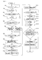
- FIG. 1 is a block diagram illustrating a configuration of a battery pack and a power supply system in Embodiment 1.
- FIG. 2 is a control flow diagram of the battery pack according to the first embodiment.
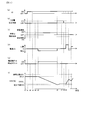
- FIG. 3 is a diagram illustrating a time chart in the battery pack according to the first embodiment.
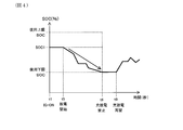
- FIG. 4 is a diagram illustrating the SOC change in the state where charging is regulated in the first embodiment.
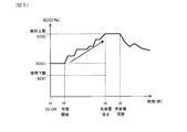
- FIG. 5 is a diagram illustrating a change in SOC in the state where discharge is regulated in the first embodiment.
- FIG. 6 is a control flow diagram in the battery pack according to the first modification.
- FIG. 7 is a control flow diagram of the battery pack according to the second modification.
- FIG. 8 is a control flow diagram in the battery pack according to the third modification.
- FIG. 9 is a control flow diagram in the battery pack according to the fourth modification.
- the battery pack 1 of the present embodiment includes a secondary battery 10, a voltage detection unit 11, a current detection unit 12, a charge state calculation unit 13, an integrated current amount calculation unit 14, a differential charge state calculation unit 15, A full charge capacity calculation unit 16 and a charge / discharge control unit 20 are provided.
- the voltage detection unit 11 detects the terminal voltage of the secondary battery 10.
- the charging state calculation unit 13 calculates the charging state SOC, that is, State Of Charge, based on the terminal voltage of the secondary battery 10.
- the current detection unit 12 detects the current that flows through the secondary battery 10.
- the charge / discharge control unit 20 controls charge / discharge of the secondary battery 10.
- the differential charge state calculation unit 15 includes a first charge state SOC1 calculated based on the first terminal voltage OCV1 detected by the voltage detection unit 11 at the first detection timing t2, and the voltage detection unit 11 at the second detection timing t7. A difference state of charge ⁇ SOC with respect to the second state of charge SOC2 calculated based on the detected second terminal voltage OCV2 is calculated.
- the integrated current amount calculation unit 14 calculates the integrated amount ⁇ Idt of the current detected by the current detection unit 12 in the target period T from the first detection timing t2 to the second detection timing t7.
- the full charge capacity calculation unit 16 is based on the difference charge state ⁇ SOC calculated by the difference charge state calculation unit 15 and the accumulated current amount ⁇ Idt calculated by the accumulated current amount calculation unit 14. Calculate the charge capacity.
- the charge / discharge control unit 20 is configured to regulate either charging or discharging of the secondary battery 10 during the target period t2 to t7.
- the battery pack 1 of the present embodiment is mounted on a vehicle, and as shown in FIG. 1, a vehicle rotating machine 101 is connected via a pack terminal 30 provided in the battery pack 1, and the pack terminal 31 is used.
- the electric load 102 and the Pb battery 103 are connected. Thereby, the power supply system 100 is configured.
- the secondary battery 10 provided in the battery pack 1 is connected to pack terminals 30 and 31 via switches 104 and 105. On / off of the charge / discharge restriction switch 104 and the charge / discharge prohibition switch 105 is controlled by the charge / discharge control unit 20 included in the control unit 2 of the battery pack 1.
- the kind of the secondary battery 10 is not limited, for example, it can be a non-aqueous secondary battery. In the present embodiment, a lithium ion battery is adopted as the secondary battery 10.
- a voltage detector 11 is connected to the secondary battery 10.
- a known voltage sensor can be used as the voltage detector 11, and the voltage detector 11 can detect the terminal voltage OCV of the secondary battery 10, that is, the Open Circuit Voltage, at a predetermined detection timing.
- the terminal voltage detected by the voltage detection unit 11 is stored in the OCV storage unit 41 included in the storage unit 4 of the battery pack 1.
- the charging state calculation unit 13 provided in the calculation unit 3 of the battery pack 1 charges the secondary battery 10 at the predetermined detection timing based on the terminal voltage at the predetermined detection timing stored in the OCV storage unit 41.
- a state SOC is calculated.
- the charging state calculation unit 13 stores in advance OCV-SOC conversion means based on the correspondence between the terminal voltage OCV and the charging state SOC in the secondary battery 10.
- the charging state calculation unit 13 can calculate the SOC at the predetermined detection timing from the OCV at the predetermined detection timing based on the OCV-SOC conversion means.
- the SOC calculated by the charging state calculation unit 13 is stored in the SOC storage unit 42 included in the storage unit 4.
- a current detector 12 is connected to the secondary battery 10.
- a known current sensor can be used as the current detection unit 12, and the current detection unit 12 can detect the current I flowing in the secondary battery 10 in a predetermined period.
- the current I detected by the current detection unit 12 is stored in the current amount storage unit 43 included in the storage unit 4.
- the accumulated current amount calculation unit 14 provided in the calculation unit 3 of the battery pack 1 integrates the secondary battery 10 in the predetermined period based on the current I that flows in the predetermined period stored in the current storage unit.
- the amount of current ⁇ Idt can be calculated.
- the integrated current amount ⁇ Idt calculated by the integrated current amount calculation unit 14 is stored in the ⁇ Idt storage unit 44 of the storage unit 4.
- the calculation unit 3 of the battery pack 1 includes a differential charge state calculation unit 15.
- the differential charge state calculation unit 15 calculates a differential charge state ⁇ SOC that is a difference between the SOC1 at the first detection timing and the SOC2 at the second detection timing, which is stored in the SOC storage unit 42.
- the calculated ⁇ SOC is stored in the ⁇ SOC storage unit 45 included in the storage unit 4.
- the full charge capacity calculation unit 16 included in the calculation unit 3 reads ⁇ Idt in a predetermined period stored in the ⁇ Idt storage unit 44 and ⁇ SOC in a predetermined period stored in the ⁇ SOC storage unit 45, and from these Calculate the full charge capacity.
- the calculation of the full charge capacity in the full charge capacity calculation unit 16 is calculated from the following formula 1, which is a relational expression of the full charge capacity, ⁇ Idt, and ⁇ SOC.
- Full charge capacity ( ⁇ Idt / ⁇ SOC) ⁇ 100 (Equation 1)
- FIG. The battery pack 1 includes a determination unit 5 that performs a determination described later based on the calculated value.
- the battery pack 1 has a charge / discharge control unit 20 in the control unit 2.
- the charge / discharge control unit 20 can regulate one of charging and discharging of the secondary battery 10 in a target period described later.
- the charge / discharge control unit 20 performs the regulation by turning on or off the switches 104 and 105 and permitting or regulating the generation of regenerative energy in the rotating machine 101.
- a charge / discharge prohibition switch 105 described later is turned on and the charge / discharge restriction switch 104 is turned off to supply power to the electric load 102 and the Pb battery 103. And the generation of regenerative energy by the rotating machine 101 is permitted.
- the regenerative energy output from the rotating machine 101 is input to the secondary battery 10, and the secondary battery 10 is charged.
- the generation of regenerative energy by the rotating machine 101 is regulated, and the electric load 102, the Pb battery 103, It is possible to supply power to the rotating machine 101. Thereby, the charge to the secondary battery 10 will be controlled.
- the charge / discharge control unit 20 can control the on / off of the charge / discharge prohibition switch 105 connected to the secondary battery 10. As a result, the charge / discharge control unit 20 can simultaneously inhibit both charging and discharging of the secondary battery 10.
- step S1 the ignition IG of the vehicle is turned ON.
- step S2 the timing when the IG is turned on is t1.
- step S2 the voltage detection unit 11 acquires the first terminal voltage OCV1 of the secondary battery 10 in step S2 shown in FIG.
- step S3 shown in FIG. 2 it is determined whether or not the polarization of the secondary battery 10 has been eliminated.
- the polarization of the secondary battery 10 is eliminated when one hour or more has elapsed since the end of the previous use of the secondary battery 10.
- the elapsed time can be measured using a counter (not shown) provided in the vehicle.
- the polarization may be forcibly eliminated by applying power to the secondary battery 10 or the like.
- step S3 If it is determined in step S3 that the polarization is not eliminated, the control is terminated. On the other hand, if it is determined in step S3 that the polarization has been eliminated, the charging state calculation unit 13 calculates the first charging state SOC1 based on OCV1 in step S4 shown in FIG. The timing for calculating the SOC1 is t3 shown in FIG. Note that step S3 may be performed before step S2 and step S4 may be performed after step S2.
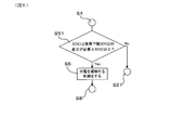
- step S5 shown in FIG. 2 it is determined whether or not the absolute value of the difference between the SOC1 and the use lower limit SOC is equal to or greater than the required differential charge state, that is, the required ⁇ SOC.
- the necessary ⁇ SOC is a ⁇ SOC used for calculating the full charge capacity, and defines the size required to reduce the calculation error.
- the required ⁇ SOC includes the type of the secondary battery 10, the configuration of the power supply system 100, It can be set in advance as appropriate according to the usage environment of the battery pack 1 and the like.
- step S6 the charge / discharge control unit 20 selects to perform control to restrict charging. Then, at the timing t4 shown in FIG. 3C, the charging regulation of the charging / discharging regulation control is turned ON. Thereby, only the discharge of the secondary battery 10 is permitted. In addition, in the state where charge regulation is ON, the state where discharge is not performed is also permitted. That is, as shown in FIG. 4, there may be a state in which discharge does not occur and the SOC does not decrease and remains flat after t5 when the charging regulation is turned on.
- step S5 the charge / discharge control unit 20 performs control for regulating discharge in step S7. Choose that. Then, the discharge regulation of the charge / discharge regulation control is turned ON. Thereby, only charging of the secondary battery 10 is permitted. In the state where the discharge regulation is ON, a state where charging is not performed is also allowed. That is, as shown in FIG. 5, there may be a state in which charging does not occur after t5 when the discharge regulation is turned on and the SOC is leveled off without increasing.
- step S8 it is determined whether or not charging of the secondary battery 10 is started. In the present embodiment, it is determined whether regenerative energy from the rotating machine 101 is applied to the secondary battery 10.
- step S9 the integrated current amount calculation unit 14 starts integrating the amount of current and starts the counter 17.
- FIG. 3D shows the current when charging is restricted, and the timing at which the current starts to be detected is t5. Then, as shown in FIG. 3 (e), current amount integration and a counter are started at t5.
- step S10 shown in FIG. 2 it is determined whether or not the terminal voltage of the secondary battery 10 has reached a predetermined end voltage X.
- the end voltage X can be set as appropriate.
- the end voltage X is an OCV equivalent to the use lower limit SOC or the use upper limit SOC derived by the OCV-SOC conversion means based on the use lower limit SOC or the use upper limit SOC.
- the OCV corresponding to the use lower limit SOC is set as the end voltage X
- the discharge regulation is performed
- the OCV corresponding to the use upper limit SOC is set as the end voltage X.
- FIG. 3 (f) shows the SOC change when charging regulation is performed, and it is determined that the terminal voltage of the secondary battery 10 has reached the end voltage X when the SOC has reached the use lower limit SOC at t6. is doing.
- Step S10 shown in FIG. 2 when it is determined that the terminal voltage of the secondary battery 10 has not reached the end voltage X, the process returns to Step S10 again. If it is determined in step S10 that the terminal voltage of the secondary battery 10 has reached the end voltage X, both charging and discharging of the secondary battery 10 are prohibited in step S11. That is, as shown in FIG. 3B, the charge / discharge inhibition control is turned ON at t6. As a result, as shown in FIG. 3D, the current value is not detected at t6.
- step S12 shown in FIG. 2 as shown in FIG. 3E, the integration of the current amount and the counter 17 are finished at t6.
- step S13 shown in FIG. 2 at t6, as shown in FIG. 3C, when the charge regulation of step S6 is performed, the charge regulation is canceled, and when the discharge regulation of step S7 is performed, the discharge regulation is performed. Is released.
- step S14 shown in FIG. 2 it is determined whether or not the polarization of the secondary battery 10 has been eliminated.
- the voltage detection unit 11 detects the second terminal voltage OCV2 that is the terminal voltage of the secondary battery 10 in step S15 shown in FIG. To do. That is, in FIGS.
- t7 is set as the second detection timing t7.
- step S16 shown in FIG. 2 the charge / discharge prohibition is canceled. That is, as shown in FIG. 3B, the charge / discharge inhibition control is turned off at t8.
- step S17 shown in FIG. 2 the charge condition calculation part 13 acquires 2nd charge condition SOC2 based on OCV2. Further, in step S18, a difference ⁇ SOC between SOC1 and SOC2 is calculated. The acquisition of SOC2 and the calculation of ⁇ SOC may be performed after t7 in FIG.
- step S19 shown in FIG. 2 the accumulated time calculated by the accumulated time calculating unit 18 is equal to or greater than the predetermined value C, the voltage detecting unit 11 is abnormal, and the current detecting unit 12 is abnormal. It is determined whether or not any of the three determination items. If it is determined in step S19 that any of the above determination items is met, the control is terminated.
- the determination method of the presence or absence of abnormality in the voltage detection part 11 and the current detection part 12 is not specifically limited, For example, the detection value by the voltage detection part 11 and the current detection part 12 by the determination part 5 and the normal set in advance By comparing with the value range, when the detected value is within the normal value range, it can be determined that there is no abnormality, and when the detected value is not within the normal value range, it can be determined that there is an abnormality.
- step S20 the full charge capacity calculation unit 16 calculates the full charge capacity, and the control for calculating the full charge capacity ends. To do. Thereafter, in step S21, after t9 shown in FIG. 3, charging / discharging of the secondary battery 10 is started under normal control.
- the effect in the battery pack 1 of this embodiment is explained in full detail.
- charging / discharging of the secondary battery 10 is restricted to one during the target period t5 to t6 in which the accumulated current amount is calculated.
- the charge / discharge period required to obtain the predetermined ⁇ SOC can be shortened, so that the offset error of the current sensor accumulated in the integrated current amount ⁇ Idt can be reduced.
- the full charge capacity of the secondary battery 10 can be accurately calculated from the relational expression between ⁇ SOC and the integrated current amount ⁇ Idt.
- the second terminal voltage is detected as the second detection timing t7 when the differential charge state ⁇ SOC is equal to or greater than the required ⁇ SOC, and the charge / discharge control unit 20 detects the first charge state SOC1 and the required ⁇ SOC. Based on the above, it is configured to determine which of charging and discharging is to be regulated. As a result, ⁇ SOC can always be greater than or equal to the required ⁇ SOC, so that the value of ⁇ SOC can be increased. As a result, an error in calculating the full charge capacity can be reduced as compared with a case where ⁇ SOC is small.
- the charge / discharge control unit 20 has an absolute value of a difference between the first charge state SOC1 and the lower limit charge state in which the use of the secondary battery 10 is allowed, that is, the use lower limit SOC is greater than or equal to the required ⁇ SOC.
- the charging of the secondary battery 10 is restricted.
- ⁇ SOC that is greater than or equal to the required ⁇ SOC can be acquired in a short time, so that an error in calculating the full charge capacity can be reduced.
- the charge / discharge control unit 20 is configured such that the absolute value of the difference between the first charge state SOC1 and the upper limit charge state in which the use of the secondary battery 10 is allowed, that is, the use upper limit SOC is greater than or equal to the required ⁇ SOC.
- the secondary battery 10 is configured to be restricted from discharging. As a result, when the first state of charge SOC1 is relatively small, ⁇ SOC that is greater than or equal to the required ⁇ SOC can be acquired in a short time, and therefore an error in calculating the full charge capacity can be reduced.
- the secondary battery 10 is in an unloaded state and the polarization of the secondary battery 10 is eliminated. It has become. Thereby, since the detection error of the terminal voltage resulting from the polarization of the secondary battery 10 can be reduced, the error in calculating the full charge capacity can be reduced. In particular, in the present embodiment, since both the first detection timing t2 and the second detection timing t7 are in a no-load state and the polarization of the secondary battery 10 is eliminated, The error in calculating the full charge capacity can be further reduced. Note that the polarization of the secondary battery 10 does not necessarily have to be completely eliminated, and may be eliminated to the extent that required SOC accuracy can be ensured.
- the charge / discharge control unit 20 is configured to release the charge regulation and the discharge regulation at the second detection timing t7. As a result, normal charge / discharge control can be performed at an early stage, and no waste occurs. In this embodiment mounted on a vehicle, a reduction in fuel consumption of the vehicle can be suppressed.
- the current detection unit 12 has an integration time calculation unit 18 that calculates the integration time when the current is detected, and when the integration time calculated by the integration time calculation unit 18 is a predetermined value C or more, When it is determined that there is an abnormality in the detection unit 11 and / or when it is determined that there is an abnormality in the current detection unit 12, the charge / discharge control unit 20 does not regulate the above.
- the full charge capacity calculation unit 16 is configured not to calculate the full charge capacity. When the accumulated time at which the current is detected is equal to or greater than the predetermined value C, the offset error of the current sensor accumulated in the accumulated current amount ⁇ Idt becomes relatively large.
- the magnitude of the predetermined value C is not particularly limited, but in the present embodiment, a value in the range of 20 to 30 minutes is set.
- the battery pack 1, the rotating machine 101 that is electrically connected to the battery pack 1 and capable of generating power input to the battery pack 1, and the battery pack 1 are electrically connected.
- the power supply system 100 having such a configuration it is possible to efficiently use energy in the entire power supply system 100 by accurately calculating the full charge capacity of the battery pack 1.
- the power supply system 100 since the power supply system 100 is mounted on the vehicle, the fuel efficiency can be improved by efficiently using energy by the power supply system 100.
- the battery pack 1 capable of accurately calculating the full charge capacity of the secondary battery 10.
- step S5 when it is determined in step S5 that the absolute value of the difference between the SOC1 and the use lower limit SOC is equal to or greater than the required ⁇ SOC, the process proceeds to step S6. It was decided to proceed to S7.
- the charge / discharge control unit 20 may restrict one of charging and discharging and not the other as in Modification 1 and Modification 2 below.
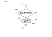
- step S51 shown in FIG. 6 instead of going to step S5. If it is determined in step S51 that the absolute value of the difference between the SOC1 and the use lower limit SOC is equal to or greater than the required ⁇ SOC, the process proceeds to step S6 and subsequent steps as in the present embodiment, but the SOC1 and the use lower limit SOC If it is determined that the absolute value of the difference is not equal to or greater than the required ⁇ SOC, the process proceeds to step S21 shown in FIG. 2 instead of proceeding to step S7, and charging / discharging is started under normal control to calculate the full charge capacity. To finish the control. Therefore, in the first modification, the charge / discharge control unit 20 regulates charging, but does not regulate discharging.
- step S52 shown in FIG. 7 instead of going to step S5. If it is determined in step S52 that the absolute value of the difference between the SOC1 and the use upper limit SOC is equal to or larger than the required ⁇ SOC, the process proceeds to step S7 and subsequent steps shown in FIG. If it is determined that the absolute value of the difference from the use upper limit SOC is not equal to or greater than the required ⁇ SOC, the control is terminated. Therefore, in the second modification, the charge / discharge control unit 20 regulates discharging but does not regulate charging.
- the charge / discharge control unit 20 since the charge / discharge control unit 20 performs only discharge regulation or charge regulation, the charge / discharge control unit 20 has a configuration for implementing both charge regulation and discharge regulation. Compared to the above, the configuration of the charge / discharge control unit 20 can be simplified, and charge / discharge control is also facilitated.
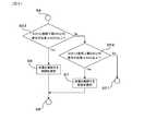
- step S53 if it is determined that the absolute value of the difference between SOC1 and the lower limit of use SOC is greater than or equal to the required ⁇ SOC, the process proceeds to step S6 and subsequent steps as in the present embodiment. If it is determined that the absolute value of the difference is not greater than or equal to the required ⁇ SOC, the process proceeds to step S54.
- step S54 If it is determined in step S54 that the absolute value of the difference between the SOC1 and the use upper limit SOC is equal to or greater than the required ⁇ SOC, the process proceeds to step S7 and subsequent steps shown in FIG. When it is determined that the absolute value of the difference from the use upper limit SOC is not equal to or greater than the required ⁇ SOC, the process proceeds to step S21 shown in FIG. 2, and charging / discharging is started by normal control, and the control for calculating the full charge capacity is ended. .
- step S54 is performed, and if it is determined in step S54 that the absolute value of the difference between SOC1 and the use upper limit SOC is not greater than or equal to the required ⁇ SOC, step S53 is performed. If it is determined in step S53 that the absolute value of the difference between SOC1 and the lower limit of use SOC is not greater than or equal to the required ⁇ SOC, the process may proceed to step S21 shown in FIG.
- the control flow according to the third modification is suitable when the required ⁇ SOC is larger than the median value between the upper limit SOC and the lower limit SOC.
- the absolute value of the difference between the value of SOC1 from both the upper limit SOC and the lower limit SOC is less than the required ⁇ SOC.
- control is performed so as not to calculate the full charge capacity.
- ⁇ SOC is a relatively large value greater than or equal to the required ⁇ SOC
- the full charge capacity is calculated, so that ⁇ SOC is close to the full charge capacity and the error in calculating the full charge capacity is reduced. be able to.
- step S201 it is determined whether or not the first detection timing t2 corresponds to a specific timing.
- the process proceeds to step S2 and subsequent steps shown in FIG. 2, and after step S2 is performed as in the present embodiment, control for calculating the full charge capacity is performed.
- step S21 shown in FIG. 2, and normal charging / discharging is started to calculate the full charge capacity. End control.
- the calculation of the full charge capacity is performed when the first detection timing t2 corresponds to the specific timing, and is not performed in other cases. As a result, it is possible to prevent the opportunity for calculating the full charge capacity from being increased more than necessary, and to efficiently use energy.
- the setting of the specific timing can be appropriately adjusted according to the required calculation frequency of the full charge capacity.
- a state in which the number of arrivals of the trip period from on to off of the IG reaches a predetermined number can be set as the specific timing.
- the full charge capacity is calculated when it falls under a specific trip at a specific timing, and the full charge capacity is not calculated for other trips. This can prevent unnecessary fuel consumption reduction.
Abstract
Selon un mode de réalisation de la présente invention, un bloc-batterie (1) est pourvu d'une batterie secondaire (10), d'une unité de calcul d'état de charge (13), d'une unité de calcul de quantité de courant intégrée (14), une unité de calcul d'état de charge différentielle (15), une unité de calcul de capacité de charge complète (16), et une unité de commande de charge et de décharge (20). L'unité de calcul d'état de charge différentielle (15) calcule un état différentiel de charge (ΔSOC) entre un premier état de charge (SOC1), à un premier moment de détection, et un second état de charge (SOC2), à un second moment de détection. L'unité de calcul de quantité de courant intégrée (14) calcule une quantité intégrée (∫Idt) d'un courant circulant vers la batterie secondaire (10) dans une période cible, du premier moment de détection au second moment de détection. L'unité de calcul de capacité de charge complète (16) calcule la capacité de charge complète de la batterie secondaire (10) sur la base de l'état de charge différentielle (ΔSOC) et de la quantité de courant intégrée (∫Idt) L'unité de commande de charge et de décharge (20) est conçue pour limiter la charge ou la décharge de la batterie secondaire (10) dans la période cible.
Priority Applications (1)
| Application Number | Priority Date | Filing Date | Title |
|---|---|---|---|
| US16/511,920 US10996280B2 (en) | 2017-01-13 | 2019-07-15 | Battery pack that calculates full charge capacity of a battery based on a state of charge |
Applications Claiming Priority (2)
| Application Number | Priority Date | Filing Date | Title |
|---|---|---|---|
| JP2017003837A JP6776904B2 (ja) | 2017-01-13 | 2017-01-13 | 電池パック及び電源システム |
| JP2017-003837 | 2017-01-13 |
Related Child Applications (1)
| Application Number | Title | Priority Date | Filing Date |
|---|---|---|---|
| US16/511,920 Continuation US10996280B2 (en) | 2017-01-13 | 2019-07-15 | Battery pack that calculates full charge capacity of a battery based on a state of charge |
Publications (1)
| Publication Number | Publication Date |
|---|---|
| WO2018131651A1 true WO2018131651A1 (fr) | 2018-07-19 |
Family
ID=62839508
Family Applications (1)
| Application Number | Title | Priority Date | Filing Date |
|---|---|---|---|
| PCT/JP2018/000496 WO2018131651A1 (fr) | 2017-01-13 | 2018-01-11 | Bloc-batterie et système d'énergie |
Country Status (3)
| Country | Link |
|---|---|
| US (1) | US10996280B2 (fr) |
| JP (1) | JP6776904B2 (fr) |
| WO (1) | WO2018131651A1 (fr) |
Cited By (2)
| Publication number | Priority date | Publication date | Assignee | Title |
|---|---|---|---|---|
| TWI670506B (zh) * | 2018-07-27 | 2019-09-01 | 連恩微電子有限公司 | 電池管理系統 |
| CN110518299A (zh) * | 2019-06-17 | 2019-11-29 | 连恩微电子有限公司 | 电池管理系统 |
Families Citing this family (3)
| Publication number | Priority date | Publication date | Assignee | Title |
|---|---|---|---|---|
| KR102244140B1 (ko) * | 2017-12-21 | 2021-04-22 | 주식회사 엘지화학 | 배터리의 충전 상태를 캘리브레이션하기 위한 방법 및 배터리 관리 시스템 |
| KR102563753B1 (ko) * | 2017-12-29 | 2023-08-04 | 삼성전자주식회사 | 배터리 충전 방법 및 장치 |
| CN111142028B (zh) * | 2020-02-20 | 2022-02-08 | 广东天波信息技术股份有限公司 | 一种锂电池电量的测量方法及装置 |
Citations (7)
| Publication number | Priority date | Publication date | Assignee | Title |
|---|---|---|---|---|
| WO2010026868A1 (fr) * | 2008-09-05 | 2010-03-11 | オムロンヘルスケア株式会社 | Sphygmomanomètre électronique fournissant des valeurs de mesure avec une fiabilité améliorée |
| US20110279094A1 (en) * | 2010-05-14 | 2011-11-17 | Toshiyuki Nakatsuji | Full charge capacity correction circuit, charging system, battery pack and full charge capacity correction method |
| WO2013141100A1 (fr) * | 2012-03-21 | 2013-09-26 | 三洋電機株式会社 | Dispositif d'estimation de l'état d'une cellule |
| WO2013157050A1 (fr) * | 2012-04-20 | 2013-10-24 | トヨタ自動車株式会社 | Véhicule |
| WO2014155434A1 (fr) * | 2013-03-25 | 2014-10-02 | トヨタ自動車株式会社 | Véhicule |
| JP2015170138A (ja) * | 2014-03-07 | 2015-09-28 | 日産自動車株式会社 | 車両走行制御情報収集装置 |
| WO2016038873A1 (fr) * | 2014-09-12 | 2016-03-17 | 日本電気株式会社 | Dispositif de contrôle, procédé de contrôle et support d'enregistrement |
Family Cites Families (73)
| Publication number | Priority date | Publication date | Assignee | Title |
|---|---|---|---|---|
| JPS5999941A (ja) * | 1982-11-26 | 1984-06-08 | 株式会社デンソー | 車両用充電制御装置 |
| US4665354A (en) * | 1984-08-08 | 1987-05-12 | Nippondenso Co., Ltd. | Battery voltage regulator for vehicles |
| US5280231A (en) * | 1990-07-02 | 1994-01-18 | Nippondenso Co., Ltd. | Battery condition detecting apparatus and charge control apparatus for automobile |
| JP3164998B2 (ja) * | 1995-04-07 | 2001-05-14 | 矢崎総業株式会社 | 電池残存容量測定装置 |
| JP3932632B2 (ja) * | 1997-11-28 | 2007-06-20 | 株式会社デンソー | 車両用電源装置 |
| JP4186092B2 (ja) * | 1999-08-18 | 2008-11-26 | ソニー株式会社 | バッテリー機器及びバッテリーの管理方法 |
| TW535308B (en) * | 2000-05-23 | 2003-06-01 | Canon Kk | Detecting method for detecting internal state of a rechargeable battery, detecting device for practicing said detecting method, and instrument provided with said |
| DE60140640D1 (de) * | 2000-05-29 | 2010-01-14 | Panasonic Corp | Batterieladeverfahren |
| JP4292721B2 (ja) * | 2001-02-14 | 2009-07-08 | 株式会社日本自動車部品総合研究所 | ハイブリッド車の電池状態制御方法 |
| JP3629553B2 (ja) * | 2001-05-08 | 2005-03-16 | インターナショナル・ビジネス・マシーンズ・コーポレーション | 電源供給システム、コンピュータ装置、電池、異常充電の保護方法、およびプログラム |
| US6639385B2 (en) * | 2001-08-07 | 2003-10-28 | General Motors Corporation | State of charge method and apparatus |
| JP3770137B2 (ja) | 2001-10-17 | 2006-04-26 | トヨタ自動車株式会社 | 車両用二次電池制御装置 |
| JP4157317B2 (ja) * | 2002-04-10 | 2008-10-01 | 株式会社日立製作所 | 状態検知装置及びこれを用いた各種装置 |
| JP2004251744A (ja) * | 2003-02-20 | 2004-09-09 | Toyota Motor Corp | 二次電池の制御装置および制御方法 |
| US7317300B2 (en) * | 2003-06-23 | 2008-01-08 | Denso Corporation | Automotive battery state monitor apparatus |
| US7521896B2 (en) * | 2004-07-20 | 2009-04-21 | Panasonic Ev Energy Co., Ltd. | Abnormal voltage detector apparatus for detecting voltage abnormality in assembled battery |
| US7233128B2 (en) * | 2004-07-30 | 2007-06-19 | Ford Global Technologies, Llc | Calculation of state of charge offset using a closed integral method |
| US7630842B2 (en) * | 2005-01-27 | 2009-12-08 | Panasonic Ev Energy Co., Ltd. | Secondary battery charge/discharge electricity amount estimation method and device, secondary battery polarization voltage estimation method and device and secondary battery remaining capacity estimation method and device |
| JP4623448B2 (ja) * | 2005-04-20 | 2011-02-02 | 株式会社デンソー | 二次電池の残存容量演算方法 |
| JP5170876B2 (ja) * | 2005-06-03 | 2013-03-27 | 古河電気工業株式会社 | 充電率/残存容量推定方法、電池の状態検知センサ及び電池電源システム |
| JP4830382B2 (ja) * | 2005-07-19 | 2011-12-07 | 日産自動車株式会社 | 二次電池の充電率推定装置 |
| US7507497B2 (en) * | 2005-09-06 | 2009-03-24 | Denso Corporation | Method and apparatus for judging degradation of storage battery |
| JP2007121030A (ja) * | 2005-10-26 | 2007-05-17 | Denso Corp | 車両用蓄電装置の内部状態検出装置 |
| KR100669470B1 (ko) * | 2005-12-22 | 2007-01-16 | 삼성에스디아이 주식회사 | 배터리의 soo 보정 방법 및 이를 이용한 배터리 관리시스템 |
| JP4984527B2 (ja) * | 2005-12-27 | 2012-07-25 | トヨタ自動車株式会社 | 二次電池の充電状態推定装置および充電状態推定方法 |
| JP2008253129A (ja) * | 2007-03-07 | 2008-10-16 | Matsushita Electric Ind Co Ltd | リチウム系二次電池の急速充電方法およびそれを用いる電子機器 |
| JP4544273B2 (ja) * | 2007-06-20 | 2010-09-15 | トヨタ自動車株式会社 | 車両用電源装置および車両用電源装置における蓄電装置の充電状態推定方法 |
| JP4650483B2 (ja) * | 2007-12-12 | 2011-03-16 | 株式会社デンソー | 車両走行制御装置 |
| US8788225B2 (en) * | 2008-06-27 | 2014-07-22 | Johnson Controls-Saft Advanced Power Solutions Llc | Cell diagnostic system and method |
| US8084996B2 (en) * | 2008-06-27 | 2011-12-27 | GM Global Technology Operations LLC | Method for battery capacity estimation |
| JP5159498B2 (ja) * | 2008-07-29 | 2013-03-06 | 三洋電機株式会社 | ハイブリッドカーの電源装置における電池の充放電制御方法 |
| JP2010104175A (ja) * | 2008-10-24 | 2010-05-06 | Panasonic Corp | 故障診断回路、電源装置、及び故障診断方法 |
| US8374807B2 (en) * | 2008-11-13 | 2013-02-12 | Lockheed Martin Corporation | Method and apparatus that detects state of charge (SOC) of a battery |
| JP4868088B2 (ja) * | 2009-03-05 | 2012-02-01 | トヨタ自動車株式会社 | ハイブリッド車両の充放電制御システムおよびその制御方法 |
| JP5439126B2 (ja) * | 2009-03-31 | 2014-03-12 | 株式会社日立製作所 | 電源装置用状態検知装置 |
| JP4978662B2 (ja) * | 2009-06-24 | 2012-07-18 | トヨタ自動車株式会社 | 充電状態推定装置および充電状態推定方法 |
| DE102009045526A1 (de) * | 2009-10-09 | 2011-04-14 | SB LiMotive Company Ltd., Suwon | Verfahren zur Initialisierung und des Betriebs eines Batteriemanagementsystems |
| JP5570782B2 (ja) * | 2009-10-16 | 2014-08-13 | 三洋電機株式会社 | 電源装置及びこれを備える車両並びに電源装置の充放電制御方法 |
| JP5375538B2 (ja) * | 2009-11-13 | 2013-12-25 | オムロンヘルスケア株式会社 | 電子血圧計 |
| JP5537913B2 (ja) * | 2009-11-30 | 2014-07-02 | 三洋電機株式会社 | 均等化装置、それを備えたバッテリシステムおよび電動車両 |
| EP2551686B1 (fr) * | 2010-03-26 | 2014-05-07 | Mitsubishi Electric Corporation | Appareil d'estimation d'un état de charge |
| JP5672778B2 (ja) * | 2010-06-08 | 2015-02-18 | 日産自動車株式会社 | バッテリ容量表示装置およびバッテリ容量表示方法 |
| JP5567956B2 (ja) * | 2010-09-16 | 2014-08-06 | 矢崎総業株式会社 | 複数組電池のセル電圧均等化装置 |
| TWI428622B (zh) * | 2010-11-25 | 2014-03-01 | Ind Tech Res Inst | 一種藉由電池充放電特性檢控容量與功率的方法 |
| JP5318128B2 (ja) * | 2011-01-18 | 2013-10-16 | カルソニックカンセイ株式会社 | バッテリの充電率推定装置 |
| US8645088B2 (en) * | 2011-05-13 | 2014-02-04 | GM Global Technology Operations LLC | Systems and methods for determining the state of charge of a battery utilizing confidence values |
| US9037426B2 (en) * | 2011-05-13 | 2015-05-19 | GM Global Technology Operations LLC | Systems and methods for determining cell capacity values in a multi-cell battery |
| JP2012247339A (ja) * | 2011-05-30 | 2012-12-13 | Renesas Electronics Corp | 半導体集積回路およびその動作方法 |
| CN103635822B (zh) * | 2011-08-30 | 2016-02-10 | 三洋电机株式会社 | 电池系统、电动车辆、移动体、电力储存装置以及电源装置 |
| US9746525B2 (en) * | 2011-09-08 | 2017-08-29 | Hitachi Automotive Systems, Ltd. | Battery system monitoring device |
| WO2013051241A1 (fr) * | 2011-10-07 | 2013-04-11 | カルソニックカンセイ株式会社 | Dispositif et procédé d'estimation d'état de charge de batterie |
| JP5393837B2 (ja) * | 2012-05-11 | 2014-01-22 | カルソニックカンセイ株式会社 | バッテリの充電率推定装置 |
| KR20150029204A (ko) * | 2013-09-09 | 2015-03-18 | 삼성에스디아이 주식회사 | 배터리 팩, 배터리 팩을 포함하는 장치, 및 배터리 팩의 관리 방법 |
| JP6098496B2 (ja) * | 2013-12-06 | 2017-03-22 | トヨタ自動車株式会社 | 蓄電システム |
| JP6300567B2 (ja) * | 2014-02-24 | 2018-03-28 | 日立オートモティブシステムズ株式会社 | 二次電池システム |
| JP2015178963A (ja) * | 2014-03-18 | 2015-10-08 | 株式会社東芝 | 算出装置及び算出方法 |
| AU2015342321B2 (en) * | 2014-11-03 | 2019-09-12 | Dalian Rongkepower Co., Ltd | Method and system for monitoring state of charge (SOC) of flow battery system, flow battery based on redundancy design of SOC detection device, method and device for determining actual capacity of flow battery, and method and system for estimating input-output characteristic of flow battery alternating current side |
| JP6490414B2 (ja) * | 2014-12-05 | 2019-03-27 | 古河電気工業株式会社 | 二次電池状態検出装置および二次電池状態検出方法 |
| WO2016129248A1 (fr) * | 2015-02-13 | 2016-08-18 | パナソニックIpマネジメント株式会社 | Dispositif et procédé d'estimation d'état de charge de batterie secondaire |
| DE112016000834T5 (de) * | 2015-02-19 | 2017-11-30 | Mitsubishi Electric Corporation | Vorrichtung zum einschätzen eines batteriestatus |
| CN107431367B (zh) * | 2015-03-02 | 2020-08-11 | 日本汽车能源株式会社 | 电池控制装置和车辆系统 |
| US20160276843A1 (en) * | 2015-03-20 | 2016-09-22 | Ford Global Technologies, Llc | Battery Charge Strategy Using Discharge Cycle |
| JP2016211924A (ja) * | 2015-05-01 | 2016-12-15 | カルソニックカンセイ株式会社 | 二次電池の充電率算出装置、及び蓄電池システム |
| WO2017046870A1 (fr) * | 2015-09-15 | 2017-03-23 | 株式会社 東芝 | Dispositif de commande de batterie rechargeable, procédé de commande, programme, système de stockage d'énergie, système d'alimentation électrique |
| US10322634B2 (en) * | 2015-10-14 | 2019-06-18 | Ford Global Technologies, Llc | Estimating battery capacity in an electric vehicle |
| JP2018046667A (ja) * | 2016-09-14 | 2018-03-22 | 株式会社東芝 | 充電パターン作成装置、充電制御装置、充電パターン作成方法、プログラム、及び蓄電システム |
| JP2018048911A (ja) * | 2016-09-21 | 2018-03-29 | 株式会社豊田自動織機 | 満充電容量推定装置 |
| JP6665757B2 (ja) * | 2016-11-08 | 2020-03-13 | 株式会社デンソー | 電源制御装置、及び電池ユニット |
| JP6677177B2 (ja) * | 2017-01-13 | 2020-04-08 | 株式会社デンソー | 制御装置 |
| JP6567582B2 (ja) * | 2017-03-08 | 2019-08-28 | 株式会社東芝 | 充放電制御装置、使用条件作成装置、プログラム、及び蓄電システム |
| JP6567583B2 (ja) * | 2017-03-15 | 2019-08-28 | 株式会社東芝 | 電池安全性評価装置、電池制御装置、電池安全性評価方法、プログラム、制御回路及び蓄電システム |
| JP6939057B2 (ja) * | 2017-04-27 | 2021-09-22 | トヨタ自動車株式会社 | 車載の電池システムおよび電池の経年劣化推定方法 |
| JP7087610B2 (ja) * | 2018-04-11 | 2022-06-21 | 株式会社デンソー | 電池制御装置 |
-
2017
- 2017-01-13 JP JP2017003837A patent/JP6776904B2/ja active Active
-
2018
- 2018-01-11 WO PCT/JP2018/000496 patent/WO2018131651A1/fr active Application Filing
-
2019
- 2019-07-15 US US16/511,920 patent/US10996280B2/en active Active
Patent Citations (7)
| Publication number | Priority date | Publication date | Assignee | Title |
|---|---|---|---|---|
| WO2010026868A1 (fr) * | 2008-09-05 | 2010-03-11 | オムロンヘルスケア株式会社 | Sphygmomanomètre électronique fournissant des valeurs de mesure avec une fiabilité améliorée |
| US20110279094A1 (en) * | 2010-05-14 | 2011-11-17 | Toshiyuki Nakatsuji | Full charge capacity correction circuit, charging system, battery pack and full charge capacity correction method |
| WO2013141100A1 (fr) * | 2012-03-21 | 2013-09-26 | 三洋電機株式会社 | Dispositif d'estimation de l'état d'une cellule |
| WO2013157050A1 (fr) * | 2012-04-20 | 2013-10-24 | トヨタ自動車株式会社 | Véhicule |
| WO2014155434A1 (fr) * | 2013-03-25 | 2014-10-02 | トヨタ自動車株式会社 | Véhicule |
| JP2015170138A (ja) * | 2014-03-07 | 2015-09-28 | 日産自動車株式会社 | 車両走行制御情報収集装置 |
| WO2016038873A1 (fr) * | 2014-09-12 | 2016-03-17 | 日本電気株式会社 | Dispositif de contrôle, procédé de contrôle et support d'enregistrement |
Cited By (3)
| Publication number | Priority date | Publication date | Assignee | Title |
|---|---|---|---|---|
| TWI670506B (zh) * | 2018-07-27 | 2019-09-01 | 連恩微電子有限公司 | 電池管理系統 |
| CN110518299A (zh) * | 2019-06-17 | 2019-11-29 | 连恩微电子有限公司 | 电池管理系统 |
| CN110518299B (zh) * | 2019-06-17 | 2022-12-09 | 连恩微电子有限公司 | 电池管理系统 |
Also Published As
| Publication number | Publication date |
|---|---|
| US10996280B2 (en) | 2021-05-04 |
| JP6776904B2 (ja) | 2020-10-28 |
| US20190339332A1 (en) | 2019-11-07 |
| JP2018112501A (ja) | 2018-07-19 |
Similar Documents
| Publication | Publication Date | Title |
|---|---|---|
| WO2018131651A1 (fr) | Bloc-batterie et système d'énergie | |
| JP5304880B2 (ja) | 電池の残存容量検出装置 | |
| JP5248764B2 (ja) | 蓄電素子の異常検出装置、蓄電素子の異常検出方法及びその異常検出プログラム | |
| JP5619744B2 (ja) | 蓄電デバイスの状態検知方法及びその装置 | |
| JP2010249797A (ja) | 二次電池の状態判定装置及び制御装置 | |
| US20120161709A1 (en) | Secondary-battery control apparatus | |
| JP5704108B2 (ja) | 電池システムおよび推定方法 | |
| JP5397013B2 (ja) | 組電池の制御装置 | |
| EP3110654B1 (fr) | Appareil de controle de charge pour un vehicule | |
| JP2010098866A (ja) | 不均衡判定回路、不均衡低減回路、電池電源装置、及び不均衡判定方法 | |
| JP2018112501A5 (fr) | ||
| JP5823292B2 (ja) | 蓄電デバイスの状態検知方法及びその装置 | |
| WO2010010662A1 (fr) | Circuit de détermination d’un déséquilibre, dispositif d’alimentation en énergie et procédé de détermination de déséquilibre | |
| JP2012253975A (ja) | アルカリ蓄電池の充放電制御方法および充放電システム | |
| JP5959566B2 (ja) | 蓄電池の制御装置 | |
| JP4494454B2 (ja) | 車載二次電池の内部状態検出装置 | |
| JP5131533B2 (ja) | バッテリの充放電制御方法及び充放電制御装置 | |
| JP2010281723A (ja) | 蓄電デバイスの状態検知方法及びその装置 | |
| JP6500795B2 (ja) | 車載バッテリのsoc管理システム | |
| JP4016881B2 (ja) | 電池の残量計測装置 | |
| JP6011265B2 (ja) | 電池システム | |
| JP6672976B2 (ja) | 充電量算出装置、コンピュータプログラム及び充電量算出方法 | |
| JP6834409B2 (ja) | バッテリシステム | |
| JP6631377B2 (ja) | 充電量算出装置、コンピュータプログラム及び充電量算出方法 | |
| JP2020048318A (ja) | 二次電池装置 |
Legal Events
| Date | Code | Title | Description |
|---|---|---|---|
| 121 | Ep: the epo has been informed by wipo that ep was designated in this application |
Ref document number: 18739253 Country of ref document: EP Kind code of ref document: A1 |
|
| NENP | Non-entry into the national phase |
Ref country code: DE |
|
| 122 | Ep: pct application non-entry in european phase |
Ref document number: 18739253 Country of ref document: EP Kind code of ref document: A1 |