WO2010010662A1 - Circuit de détermination d’un déséquilibre, dispositif d’alimentation en énergie et procédé de détermination de déséquilibre - Google Patents
Circuit de détermination d’un déséquilibre, dispositif d’alimentation en énergie et procédé de détermination de déséquilibre Download PDFInfo
- Publication number
- WO2010010662A1 WO2010010662A1 PCT/JP2009/003137 JP2009003137W WO2010010662A1 WO 2010010662 A1 WO2010010662 A1 WO 2010010662A1 JP 2009003137 W JP2009003137 W JP 2009003137W WO 2010010662 A1 WO2010010662 A1 WO 2010010662A1
- Authority
- WO
- WIPO (PCT)
- Prior art keywords
- power storage
- voltage
- terminal voltage
- unit
- terminal
- Prior art date
Links
Images


Classifications
-
- H—ELECTRICITY
- H02—GENERATION; CONVERSION OR DISTRIBUTION OF ELECTRIC POWER
- H02J—CIRCUIT ARRANGEMENTS OR SYSTEMS FOR SUPPLYING OR DISTRIBUTING ELECTRIC POWER; SYSTEMS FOR STORING ELECTRIC ENERGY
- H02J7/00—Circuit arrangements for charging or depolarising batteries or for supplying loads from batteries
- H02J7/0013—Circuit arrangements for charging or depolarising batteries or for supplying loads from batteries acting upon several batteries simultaneously or sequentially
- H02J7/0014—Circuits for equalisation of charge between batteries
- H02J7/0016—Circuits for equalisation of charge between batteries using shunting, discharge or bypass circuits
-
- H—ELECTRICITY
- H01—ELECTRIC ELEMENTS
- H01M—PROCESSES OR MEANS, e.g. BATTERIES, FOR THE DIRECT CONVERSION OF CHEMICAL ENERGY INTO ELECTRICAL ENERGY
- H01M10/00—Secondary cells; Manufacture thereof
- H01M10/42—Methods or arrangements for servicing or maintenance of secondary cells or secondary half-cells
- H01M10/48—Accumulators combined with arrangements for measuring, testing or indicating the condition of cells, e.g. the level or density of the electrolyte
- H01M10/482—Accumulators combined with arrangements for measuring, testing or indicating the condition of cells, e.g. the level or density of the electrolyte for several batteries or cells simultaneously or sequentially
-
- G—PHYSICS
- G01—MEASURING; TESTING
- G01R—MEASURING ELECTRIC VARIABLES; MEASURING MAGNETIC VARIABLES
- G01R19/00—Arrangements for measuring currents or voltages or for indicating presence or sign thereof
- G01R19/165—Indicating that current or voltage is either above or below a predetermined value or within or outside a predetermined range of values
- G01R19/16533—Indicating that current or voltage is either above or below a predetermined value or within or outside a predetermined range of values characterised by the application
- G01R19/16538—Indicating that current or voltage is either above or below a predetermined value or within or outside a predetermined range of values characterised by the application in AC or DC supplies
- G01R19/16542—Indicating that current or voltage is either above or below a predetermined value or within or outside a predetermined range of values characterised by the application in AC or DC supplies for batteries
-
- H—ELECTRICITY
- H01—ELECTRIC ELEMENTS
- H01M—PROCESSES OR MEANS, e.g. BATTERIES, FOR THE DIRECT CONVERSION OF CHEMICAL ENERGY INTO ELECTRICAL ENERGY
- H01M10/00—Secondary cells; Manufacture thereof
- H01M10/42—Methods or arrangements for servicing or maintenance of secondary cells or secondary half-cells
- H01M10/425—Structural combination with electronic components, e.g. electronic circuits integrated to the outside of the casing
-
- H—ELECTRICITY
- H01—ELECTRIC ELEMENTS
- H01M—PROCESSES OR MEANS, e.g. BATTERIES, FOR THE DIRECT CONVERSION OF CHEMICAL ENERGY INTO ELECTRICAL ENERGY
- H01M10/00—Secondary cells; Manufacture thereof
- H01M10/42—Methods or arrangements for servicing or maintenance of secondary cells or secondary half-cells
- H01M10/46—Accumulators structurally combined with charging apparatus
- H01M10/465—Accumulators structurally combined with charging apparatus with solar battery as charging system
-
- G—PHYSICS
- G01—MEASURING; TESTING
- G01R—MEASURING ELECTRIC VARIABLES; MEASURING MAGNETIC VARIABLES
- G01R31/00—Arrangements for testing electric properties; Arrangements for locating electric faults; Arrangements for electrical testing characterised by what is being tested not provided for elsewhere
- G01R31/36—Arrangements for testing, measuring or monitoring the electrical condition of accumulators or electric batteries, e.g. capacity or state of charge [SoC]
- G01R31/396—Acquisition or processing of data for testing or for monitoring individual cells or groups of cells within a battery
-
- H—ELECTRICITY
- H01—ELECTRIC ELEMENTS
- H01M—PROCESSES OR MEANS, e.g. BATTERIES, FOR THE DIRECT CONVERSION OF CHEMICAL ENERGY INTO ELECTRICAL ENERGY
- H01M10/00—Secondary cells; Manufacture thereof
- H01M10/05—Accumulators with non-aqueous electrolyte
- H01M10/052—Li-accumulators
- H01M10/0525—Rocking-chair batteries, i.e. batteries with lithium insertion or intercalation in both electrodes; Lithium-ion batteries
-
- Y—GENERAL TAGGING OF NEW TECHNOLOGICAL DEVELOPMENTS; GENERAL TAGGING OF CROSS-SECTIONAL TECHNOLOGIES SPANNING OVER SEVERAL SECTIONS OF THE IPC; TECHNICAL SUBJECTS COVERED BY FORMER USPC CROSS-REFERENCE ART COLLECTIONS [XRACs] AND DIGESTS
- Y02—TECHNOLOGIES OR APPLICATIONS FOR MITIGATION OR ADAPTATION AGAINST CLIMATE CHANGE
- Y02E—REDUCTION OF GREENHOUSE GAS [GHG] EMISSIONS, RELATED TO ENERGY GENERATION, TRANSMISSION OR DISTRIBUTION
- Y02E60/00—Enabling technologies; Technologies with a potential or indirect contribution to GHG emissions mitigation
- Y02E60/10—Energy storage using batteries
-
- Y—GENERAL TAGGING OF NEW TECHNOLOGICAL DEVELOPMENTS; GENERAL TAGGING OF CROSS-SECTIONAL TECHNOLOGIES SPANNING OVER SEVERAL SECTIONS OF THE IPC; TECHNICAL SUBJECTS COVERED BY FORMER USPC CROSS-REFERENCE ART COLLECTIONS [XRACs] AND DIGESTS
- Y02—TECHNOLOGIES OR APPLICATIONS FOR MITIGATION OR ADAPTATION AGAINST CLIMATE CHANGE
- Y02T—CLIMATE CHANGE MITIGATION TECHNOLOGIES RELATED TO TRANSPORTATION
- Y02T10/00—Road transport of goods or passengers
- Y02T10/60—Other road transportation technologies with climate change mitigation effect
- Y02T10/70—Energy storage systems for electromobility, e.g. batteries
Definitions
- the present invention relates to an imbalance determination circuit, a power supply device, and an imbalance determination method for determining whether or not an imbalance of the amount of electricity stored in a plurality of power storage units has occurred.
- a power storage device using a power storage unit or the like is widely used as a power supply system in combination with a solar battery or a power generation device.
- the power generation device is driven by natural energy such as wind power or hydraulic power or artificial power such as an internal combustion engine.
- a power supply system that combines such power storage devices is designed to improve energy efficiency by storing surplus power in the power storage device and supplying power from the power storage device when a load device is required.
- An example of such a system is a solar power generation system.
- the solar power generation system charges the power storage device with surplus power when the amount of power generated by sunlight is larger than the power consumption of the load device.
- the load device is driven by outputting from the power storage device in order to compensate for the insufficient power.
- surplus power that has not been used in the past can be stored in the power storage device, so that energy efficiency can be improved compared to a power supply system that does not use the power storage device.
- charge control is performed so that the state of charge of the power storage unit (hereinafter referred to as SOC: State Of Charge) does not become 100%.
- SOC State Of Charge
- charging control is performed so that the SOC does not become 0 (zero)% so that the load device can be driven when necessary.
- charging control is normally performed so that the SOC changes within a range of 20% to 80%.
- a hybrid vehicle (HEV: Hybrid Electric Vehicle) using an engine and a motor also uses such a principle.
- HEV Hybrid Electric Vehicle
- the HEV drives the generator with the surplus engine output and charges the power storage device.
- the HEV charges the power storage device by using the motor as a generator during braking or deceleration of the vehicle.
- the load leveling power source is a system that stores power in a power storage device at night when the power consumption is low and the power rate is low, and uses the stored power during the day when the power consumption peaks.
- the purpose is to make the power generation amount constant by smoothing the power consumption, and to contribute to the efficient operation of power facilities and the reduction of capital investment.
- Plug-in hybrid vehicles use electric power at night, mainly EV driving to supply power from the power storage device when driving in urban areas with poor fuel efficiency, and by HEV driving using the engine and motor during long distance driving, The aim is to reduce the total CO 2 emissions.
- such a power storage device is configured by connecting a plurality of power storage elements (such as single cells) in series in order to obtain a desired output voltage.
- a power storage element when a deep discharge is performed in a state where the amount of stored charge of each power storage element varies, the power storage element with a small amount of stored charge is further overdischarged, and the power storage element deteriorates and the entire power storage device This will reduce the lifespan.
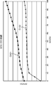
- FIG. 8 is a graph showing the relationship between the SOC and the terminal voltage of a secondary battery (for example, a lithium ion secondary battery).
- the horizontal axis of FIG. 8 indicates the SOC, and the vertical axis indicates the terminal voltage when the secondary battery is not loaded, that is, the OCV.
- a graph G101 in FIG. 8 generally, as the charging progresses and the SOC increases, the terminal voltage of the secondary battery increases.
- the change in the amount of stored charge is easily reflected in the terminal voltage, so that the detection accuracy of the variation in the stored charge amount is good.
- some storage elements have a flat voltage characteristic with a small change in the terminal voltage with respect to the change in the SOC, that is, the stored charge amount, as shown by a graph G102 in FIG.
- the terminal voltage changes gently with respect to the change in SOC. Therefore, if the SOC is detected based on the terminal voltage, The detection accuracy of variation will be reduced. For example, the actual SOC may be erroneously detected as 80% even though it is 20%.
- the storage device is charged and discharged while the stored charge amount variation occurs, and among the plurality of storage elements, those with a small stored charge amount are overdischarged, As a result of overcharging those having a large amount of charge, there is a disadvantage that the power storage element deteriorates and the life deterioration of the entire power storage device is accelerated.
- An object of the present invention is to provide an imbalance determination circuit, a power supply device, and an imbalance determination method that can improve the determination accuracy of whether or not an imbalance has occurred in each storage amount in a plurality of power storage units. is there.
- An imbalance determination circuit includes: a voltage detection unit that detects a terminal voltage in each of a plurality of power storage units; and a charging current supplied to each power storage unit, whereby the terminal voltage of each power storage unit is A first terminal voltage acquisition unit that acquires a terminal voltage of each power storage unit detected by the voltage detection unit as a plurality of first terminal voltages respectively corresponding to each power storage unit during a period in which polarization occurs; The terminal voltage of each power storage unit detected by the voltage detection unit during the charging stop period after the plurality of first terminal voltages are acquired by the first terminal voltage acquisition unit corresponds to each power storage unit.
- the imbalance determination method provides a method for detecting each power storage during a period in which the terminal voltage of each power storage unit is polarized by supplying a charging current to each power storage unit.
- Voltage change calculated as voltage change amount When at least one of the differences between the calculation step and the calculated voltage change amounts exceeds a preset determination threshold value, there is an imbalance of the storage amounts
- the terminal voltage of each power storage unit detected during the period in which the terminal voltage deviates from the stable OCV (Open circuit voltage) due to the charging current being supplied to each power storage unit. are acquired as a plurality of first terminal voltages respectively corresponding to the respective power storage units.
- the terminal voltages of the respective power storage units detected during the charging stop period are acquired as the plurality of second terminal voltages respectively corresponding to the respective power storage units.
- a difference for each value corresponding to each power storage unit between each first terminal voltage and each second terminal voltage is calculated as a voltage change amount corresponding to each power storage unit.
- the inventors of the present application have found that the difference between the terminal voltage of the power storage unit that has been polarized by charging and the terminal voltage of the power storage unit that has been reduced in polarization at least after stopping charging is different depending on the SOC of the power storage unit. Then, since the difference between the first terminal voltage and the second terminal voltage changes according to the SOC of the power storage unit, even when a power storage unit having a small change in terminal voltage with respect to the change in SOC is used, By determining whether or not an imbalance has occurred based on the difference between the first terminal voltage and the second terminal voltage, as in the background art, it is possible to determine whether or not there is an imbalance directly from the difference in terminal voltage between power storage units. Compared to the determination, it is possible to improve the determination accuracy of whether or not an imbalance has occurred.
- a power supply device includes the imbalance determination circuit, the plurality of power storage units, the discharge unit that discharges the plurality of power storage units, and the imbalance determination unit.
- a forced discharge control unit that discharges each power storage unit by the discharge unit until a terminal voltage detected by the voltage detection unit is equal to or lower than a preset target voltage.
- the discharge unit discharges each terminal voltage of each power storage unit to a target voltage or less, Imbalance is reduced.
- the imbalance determination circuit, the power supply device, and the imbalance determination method having such a configuration, the difference between the terminal voltage of the power storage unit during charging and the terminal voltage of the power storage unit after stopping charging according to the SOC of the power storage unit Is used to determine whether or not there is an imbalance in the amount of electricity stored in each storage battery. Therefore, even when a power storage unit with a small change in terminal voltage with respect to a change in SOC is used, the background art Thus, the determination accuracy of whether or not an imbalance has occurred can be improved as compared with the case where the presence or absence of an imbalance is directly determined from the difference in terminal voltage between the power storage units.
- FIG. 3 It is a block diagram which shows an example of the structure of the imbalance determination circuit using the imbalance determination method which concerns on one Embodiment of this invention, and the power supply device provided with this imbalance determination circuit. It is explanatory drawing for demonstrating the change of a terminal voltage when charging current is made into zero after flowing charging current into an electrical storage element. It is a block diagram which shows an example of a structure of the voltage detection part shown in FIG. It is a block diagram which shows another example of a structure of the voltage detection part shown in FIG. 3 is a flowchart illustrating an example of an operation of the power supply device illustrated in FIG. 1. 3 is a flowchart illustrating an example of an operation of the power supply device illustrated in FIG. 1. 3 is a flowchart illustrating an example of an operation of the power supply device illustrated in FIG. 1. It is a graph which shows the relationship between SOC of a electrical storage body, and a terminal voltage.
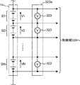
- FIG. 1 is a block diagram illustrating an example of a configuration of an imbalance determination circuit using an imbalance determination method according to an embodiment of the present invention, a power supply device including the imbalance determination circuit, and a power supply system.
- the power supply system 1 shown in FIG. 1 includes a power generation device 10, a power supply control device 30, and a power storage device 40.
- the power supply control device 30 and the power storage device 40 constitute a power supply device 50.
- the power supply device 50 includes, for example, a battery pack, an uninterruptible power supply device, a power generation device that utilizes natural energy, a power storage device that stores surplus power of a power generation device that uses an engine as a power source, a load leveling power source, and the like Used as various power supply devices.
- the power device 50 is connected to the load device 20 that receives power from the power generation device 10 and the power storage device 40.
- the power generation device 10 is, for example, a power generation device using natural energy such as a solar power generation device (solar battery) or a generator using an engine as a power source.
- the power supply device 50 may be configured to receive power supply from a commercial power supply instead of the power generation device 10.
- the power storage device 40 is configured by connecting N power storage units B1, B2,..., BN in series.
- the power storage units B1, B2,..., BN are accommodated in a box (not shown).
- each of the power storage units B1, B2,..., BN is configured by electrically connecting a plurality of power storage elements 401 in series.
- a power storage element such as an alkaline storage battery such as a nickel metal hydride battery, an organic battery such as a lithium ion battery, and a capacitor such as an electric double layer capacitor can be used.
- the power storage element 401 has a flat characteristic with little change in the terminal voltage with respect to the change in the SOC, for example, as shown in a graph G102 in FIG.
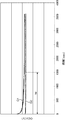
- FIG. 2 shows a case where the charging current is made zero after charging current is passed through a lithium ion secondary battery using LiFePO 4 which is an example of olivine lithium composite phosphate as a positive electrode active material (when charging is stopped).
- LiFePO 4 which is an example of olivine lithium composite phosphate as a positive electrode active material (when charging is stopped).
- Graph G1 shows a case where charging is stopped when the SOC is 100%
- graph G2 shows a case where charging is stopped when the SOC is 70%.
- the vertical axis in FIG. 2 shows the terminal voltage (OCV) of the secondary battery, and the horizontal axis shows the elapsed time since charging was stopped.
- the storage element 401 shows that the amount of decrease in the terminal voltage (the amount of decrease in a predetermined time) until it reaches a steady value after stopping charging increases as the amount of storage increases. Larger power storage elements are used as they are closer to charging.
- a lithium ion secondary battery using LiFePO 4 which is an example of an olivine-based lithium composite phosphate can be suitably used as the power storage element 401, for example, as a positive electrode active material.
- the positive electrode active material for example, Li X A Y B Z PO 4 (A is Me, Fe, Mn, Co, Ni, at least one of Cu, B is Mg, Ca, Sr, Sc, Y, At least one of Ti, Zr, V, Nb, Cr, Mo, W, Ag, Zn, In, Sn, and Sb, 0 ⁇ X ⁇ 1, 0.9 ⁇ Y ⁇ 1, 0 ⁇ Z ⁇ 0.1) More preferably, LixFePO 4 (0 ⁇ X ⁇ 1) may be used.
- a lithium ion secondary battery using LiFePO 4 as a positive electrode active material is flat with a small change in terminal voltage with respect to a change in SOC in a wide region, for example, as shown by a graph G102 in FIG.
- the power storage element 401 a power storage unit in which the amount of change in the terminal voltage when the SOC changes from 10% to 95% is 0.01 V or more and less than 0.3 V can be used.
- the inventors of the present invention in the lithium ion secondary battery using LiFePO 4 as the positive electrode active material, the amount of decrease in the terminal voltage per predetermined time after the charge is stopped increases as the SOC increases. It has been found experimentally that it has the property of increasing.
- each power storage unit may be configured by connecting a plurality of power storage elements 401 in series, parallel, or a combination of series and parallel.
- Each power storage unit may be one power storage element 401.
- the configuration of the power storage device 40 is not limited to the above.
- the power supply control device 30 is configured as an in-vehicle ECU (Electric Control Unit), for example.
- the power supply control device 30 includes a discharge unit 310, an imbalance determination circuit 350, and a charge / discharge control circuit 340.
- the imbalance determination circuit 350 includes a voltage detection unit 320 and a control unit 330.
- the charge / discharge control circuit 340 charges the power storage device 40 with, for example, surplus power generated in the power generation device 10 or regenerative power generated in the load device 20. Further, when the current consumption of the load device 20 suddenly increases or the power generation amount of the power generation device 10 decreases and the power required by the load device 20 exceeds the output of the power generation device 10, the charge / discharge control circuit 340 Thus, the insufficient power is supplied from the power storage device 40 to the load device 20.
- the charge / discharge control circuit 340 is configured to stop or permit charging of the power storage device 40 in accordance with a control signal from the control unit 330.
- the charge / discharge control circuit 340 or the power generation device 10 corresponds to an example of a charging unit.
- the charge / discharge of the power storage device 40 is controlled by the charge / discharge control circuit 340 so that the SOC of the power storage device 40 is in a range of about 20 to 80% in a normal case.
- the power storage device 40 is charged to a state where the SOC is 100%, and the load device 20 is discharged when energy is required. It has become.
- the voltage detector 320 detects the terminal voltages V1, V2,..., VN of the power storage units B1, B2,... BN, and outputs the detected values to the controller 330.
- FIG. 3 is a block diagram showing an example of the configuration of the voltage detection unit 320 shown in FIG.
- the voltage detection unit 320 illustrated in FIG. 3 includes, for example, an analog-digital converter 321 (voltage measurement unit) and a switching circuit 322 (switching unit). Note that the voltage measurement unit is not limited to an analog-digital converter, and may be a voltage detection circuit such as a comparator, for example.
- the switching circuit 322 is configured using, for example, a plurality of switching elements. Then, the switching circuit 322 turns on and off the plurality of switching elements in accordance with a control signal from the control unit 330, whereby the terminal voltages V1, V2,. .., VN is selected and output to the analog-digital converter 321.
- the analog-digital converter 321 converts the voltage output from the switching circuit 322 into a digital value and outputs the digital value to the control unit 330.
- control unit 330 causes the switching circuit 322 to sequentially select the terminal voltages V1, V2,..., VN, so that the terminal voltages V1, V2,. To obtain data indicating terminal voltages V1, V2,..., VN.
- the voltage detection unit 320 a may be configured by N voltage measurement units 323 that respectively detect the terminal voltages V ⁇ b> 1, V ⁇ b> 2,. In this case, since the terminal voltages V1, V2,..., VN can be detected simultaneously, the detection time of the terminal voltages V1, V2,.
- the discharge unit 310 includes N resistors R1, R2,..., RN and N transistors Q1, Q2,.
- a series circuit of the resistor R1 and the transistor Q1 is connected in parallel to the power storage unit B1
- a series circuit of the resistor R2 and the transistor Q2 is connected in parallel to the power storage unit B2, and so on.
- a circuit is connected in parallel with each power storage unit.
- the transistors Q1, Q2,..., QN are turned on and off in accordance with the equalized discharge signals SG1, SG2,.
- the transistors Q1, Q2,..., QN are turned on, the power storage unit connected in parallel with the turned-on transistors is discharged via a resistor.
- the control unit 330 includes, for example, a CPU (Central Processing Unit) that executes predetermined arithmetic processing, a ROM (Read Only Memory) that stores a predetermined control program, and a RAM (Random Access Memory) that temporarily stores data. And a timer circuit 336 and peripheral circuits thereof.
- a CPU Central Processing Unit
- ROM Read Only Memory
- RAM Random Access Memory
- control unit 330 executes, for example, a control program stored in the ROM, so that the first terminal voltage acquisition unit 331, the second terminal voltage acquisition unit 332, the voltage change calculation unit 333, the imbalance determination unit 334, and It functions as the forced discharge control unit 335.
- the charge / discharge control circuit 340 and the load device 20 may be configured to include a part or all of the control unit 330.
- the first terminal voltage acquisition unit 331 is a storage unit B1, B2,... Detected by the voltage detection unit 320 during a charging period in which the charging current is supplied from the charge / discharge control circuit 340 to the power storage device 40 and is charged. .., BN terminal voltages V1, V2,..., VN are obtained as a plurality of first terminal voltages V1a, V2a,. For example, it is stored in a RAM.
- the 1st terminal voltage acquisition part 331 is not restricted to the example which acquires 1st terminal voltage V1a, V2a, ..., VNa during a charge period, For example, immediately after charge is stopped or after charge stops The first terminal voltages V1a, V2a,..., VNa may be acquired during a polarization remaining period set in advance as a period in which polarization still remains.
- the second terminal voltage acquisition unit 332 is a charging current supplied from the charge / discharge control circuit 340 to the power storage device 40 after the first terminal voltage acquisition unit 331 acquires the first terminal voltages V1a, V2a,.
- the terminal voltages V1, V2,..., VN of the power storage units B1, B2,. are obtained as a plurality of second terminal voltages V1b, V2b,..., VNb respectively corresponding to the power storage units B1, B2,.
- the second terminal voltage acquisition unit 332 acquires the second terminal voltages V1b, V2b,..., VNb after the charging is stopped and the polarization generated in the power storage units B1, B2,. However, even if the polarization is not eliminated, a preset set time after the first terminal voltage acquisition unit 331 acquires the first terminal voltages V1a, V2a,. For example, the second terminal voltages V1b, V2b,..., VNb may be acquired after 1 second has elapsed.
- the voltage change calculation unit 333 includes first terminal voltages V1a, V2a,..., VNa acquired by the first terminal voltage acquisition unit 331 and second terminal voltages V1b, V2b acquired by the second terminal voltage acquisition unit 332. ,..., VNb, and the difference between the first terminal voltages V1a, V2a,..., VNa and the second terminal voltages V1b, V2b,. Are calculated as voltage change amounts ⁇ V1, ⁇ V2,..., ⁇ VN corresponding to the power storage units B1, B2,.
- the second terminal voltage acquisition unit 332 receives the first terminal voltages V1a, V2a,..., VNa after the first terminal voltage acquisition unit 331 acquires the first terminal voltages V1a, V2a,. ,..., VNb is acquired, the voltage change amounts ⁇ V1, ⁇ V2,..., ⁇ VN reflect the voltage drop rate in the process of eliminating the polarization. Since this descent speed is also affected by the SOC, it can be used to determine the SOC imbalance.
- the imbalance determination unit 334 includes at least one of all combinations for selecting two voltage change amounts from the voltage change amounts ⁇ V1, ⁇ V2,..., ⁇ VN calculated by the voltage change calculation unit 333.
- ⁇ V1, ⁇ V2,..., ⁇ VN calculated by the voltage change calculation unit 333.
- the terminal voltages V1, V2,..., VN detected by the voltage detection unit 320 are preset. Discharge of each power storage unit by the discharge unit 310 until the target voltage Vtg or less is reached, thereby reducing variation in stored charge amount in the power storage units B1, B2,.
- the timer circuit 336 is used by the voltage detection unit 320 to periodically detect the terminal voltages V1, V2,..., VN, for example, every unit time, or to measure the elapsed time from the stop of charging. It is done.
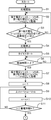
- FIG. 5 to 7 are flowcharts showing an example of the operation of the power supply device 50 shown in FIG.
- the first terminal voltage acquisition unit 331 is preset by the charge / discharge control circuit 340 from the power generation device 10 to the power storage device 40 by outputting a request signal for requesting the charge / discharge control circuit 340 to perform charging.
- a charging current having a set current value Icc is supplied.
- charging of power storage device 40 is started (step S1).
- the charging of the power storage device 40 is not necessarily started in response to a request signal from the first terminal voltage acquisition unit 331.
- the first terminal voltage acquisition unit 331 starts charging from the charge / discharge control circuit 340.
- the first terminal voltage acquisition unit 331 proceeds to step S2 when a signal indicating that the charging current is received or when it is detected by a current detection circuit (not shown) that the charging current is flowing in the power storage device 40. It may be.
- the terminal voltage to be detected is sequentially switched by the switching circuit 322, whereby the voltage detection unit 320 causes the power storage units B 1, B 2,. .. BN terminal voltages V1, V2,..., VN are detected.
- the terminal voltages V1, V2,..., VN may be detected simultaneously by the voltage detector 320a.
- the first terminal voltage acquisition unit 331 temporarily acquires the terminal voltages V1, V2,..., VN thus obtained as the first terminal voltages V1a, V2a,. S2).
- the first terminal voltage acquisition unit 331 compares the first terminal voltages V1a, V2a,..., VNa with a preset reference voltage ⁇ (step S3). If any one of the first terminal voltages V1a, V2a,..., VNa does not satisfy the reference voltage ⁇ , the process returns to step S2 and the charging continues and the first terminal voltages V1a, V2a,. , VNa provisional acquisition is repeated (NO in step S3). On the other hand, if all of the first terminal voltages V1a, V2a,..., VNa are equal to or higher than the reference voltage ⁇ (YES in step S3), the first terminal voltage acquisition unit 331 obtains the temporarily acquired first terminal voltage V1a. , V2a,..., VNa are definitely acquired, and the process proceeds to step S4 to acquire the second terminal voltages V1b, V2b,.
- the determination of imbalance is performed after all of the power storage units B1, B2,..., BN are charged to the reference voltage ⁇ or higher.
- step S4 the process proceeds to step S4 to continue the imbalance determination process.
- the opportunity to stop charging in step S4 can be reduced.
- the forced discharge control unit 335 causes the power storage units B1, B2,... Until each terminal voltage becomes equal to or lower than the target voltage Vtg. .. Reduces imbalance by discharging BN, respectively. Therefore, if the terminal voltages V1, V2,..., VN are lower than the target voltage Vtg before the discharge by the forced discharge control unit 335, the imbalance cannot be reduced by the discharge.
- step S4 the second terminal voltage acquisition unit 332 outputs a control signal requesting to stop charging to the charge / discharge control circuit 340, and the charge / discharge control circuit 340 reduces the charge / discharge current of the power storage device 40 to zero.
- the charging is stopped (step S4).
- the 2nd terminal voltage acquisition part 332 starts the timing of the timer circuit 336 (step S5). Then, the timer circuit 336 measures the elapsed time from the stop of charging.
- the charging of the power storage device 40 is not necessarily stopped in accordance with the request signal from the second terminal voltage acquisition unit 332.
- the second terminal voltage acquisition unit 332 receives a signal indicating that charging is stopped from the charge / discharge control circuit 340, or the charging current flowing through the power storage device 40 has become substantially zero by a current detection circuit (not shown). May be detected, the second terminal voltage acquisition unit 332 may proceed to step S5 and start the timer circuit 336 to measure time.
- step S6 when the elapsed time counted by timer circuit 336 continues beyond preset time ⁇ (YES in step S6), power storage units B1, B2, and B2 are detected by voltage detector 320 in the same manner as in step S2. ..., terminal voltages V1, V2, ..., VN of BN are detected. And the 2nd terminal voltage acquisition part 332 acquires terminal voltage V1, V2, ..., VN obtained in this way as 2nd terminal voltage V1b, V2b, ..., VNb (step S7). ).
- the set time ⁇ is a time longer than the time tw required for the terminal voltages V1, V2,..., VN to stabilize after the charging current becomes zero in the graph G1 having a large SOC. Is preset. Thereby, since the second terminal voltages V1b, V2b,..., VNb are acquired after the terminal voltages V1, V2,..., VN are stabilized, the second terminal voltages V1b, V2b,. The accuracy of VNb is improved.
- step S8 “1” is substituted into the variable n by the voltage change calculation unit 333 (step S8). Then, the voltage change calculation unit 333 subtracts the second terminal voltage Vnb from the first terminal voltage Vna to calculate the voltage change amount ⁇ Vn (step S9).
- step S10 After 1 is added to the variable n by the voltage change calculation unit 333 (step S10), the variable n is compared with the number N of power storage units (step S11). If the variable n is less than the number N of power storage units (NO in step S11), the process proceeds to step S9 again to calculate the voltage change amount ⁇ Vn for the next power storage unit. On the other hand, if variable n is greater than or equal to the number N of power storage units (YES in step S11), calculation of voltage change amounts ⁇ V1, ⁇ V2,. Transition.
- the voltage change calculation unit 333 obtains the maximum value of the voltage change amounts ⁇ V1, ⁇ V2,..., ⁇ VN as the maximum voltage change amount ⁇ Vmax (step S21), and the voltage change amounts ⁇ V1, ⁇ V The minimum value of V2,..., ⁇ VN is acquired as the minimum voltage change amount ⁇ Vmin (step S22).
- the imbalance determination unit 334 compares the difference between the maximum voltage change amount ⁇ Vmax and the minimum voltage change amount ⁇ Vmin with the determination threshold value ⁇ (step S23). If the difference between the maximum voltage change amount ⁇ Vmax and the minimum voltage change amount ⁇ Vmin is equal to or smaller than the determination threshold value ⁇ (NO in step S23), it is considered that an imbalance that requires equalization does not occur. Then, the imbalance determination process is terminated without determining that an imbalance has occurred.
- step S23 determines that an imbalance that requires equalization has occurred. It determines with imbalance having arisen, notifies the forced discharge control part 335 and the charge / discharge control circuit 340 that imbalance has arisen, and transfers to equalization processing.
- the imbalance determination unit 334 when at least one of the differences between the voltage changes ⁇ V1, ⁇ V2,..., ⁇ VN exceeds the determination threshold ⁇ , the imbalance determination unit 334 always makes an imbalance. Is determined to occur, and the process proceeds to equalization processing.
- the imbalance determining unit 334 may determine that an imbalance has occurred.
- the power storage units B1, B2,..., VNb are based on the differences between the first terminal voltages V1a, V2a,..., VNa and the second terminal voltages V1b, V2b,. It is determined whether or not there is an imbalance (variation) in the amount of electricity stored in B2,.
- the electrical storage element 401 the amount of decrease in the terminal voltage that occurs when charging is stopped increases as the SOC increases.
- a power storage element that decreases as the SOC increases can also be used as the power storage element 401.
- FIG. 7 is a flowchart showing an example of equalization processing.
- the forced discharge control unit 335 starts the equalization process by turning on the equalization discharge signals SG1, SG2,..., SGN and turning on the transistors Q1, Q2,. Step S31).
- the forced discharge control unit 335 starts the inspection of the terminal voltages V1, V2,..., VN (step S32), and simultaneously starts the timer circuit 336 (step S33). . Then, the forced discharge control unit 335 substitutes “1” for the variable n and starts a voltage test from the first power storage unit (step S34), and whether or not the nth equalization discharge signal SGn is turned on. Is determined (step S35).
- step S35 If the equalization discharge signal SGn is off (NO in step S35), the process proceeds to step S38. On the other hand, if the equalization discharge signal SGn is on (YES in step S35), the forced discharge control unit 335 It is determined whether the nth terminal voltage Vn is equal to or lower than the target voltage Vtg (step S36). If the terminal voltage Vn exceeds the target voltage Vtg (NO in step S36), the process proceeds to step S38. On the other hand, if the terminal voltage Vn is equal to or lower than the target voltage Vtg (YES in step S36), the forced discharge control unit 335 is performed. Turns off the equalization discharge signal SGn (turns off the transistor Qn) to finish discharging the power storage unit Bn, and stores the power storage unit number n and the end time (step S37).
- step S38 the forced discharge control unit 335 adds “1” to the variable n (step S38), and compares the variable n with the number N of power storage units (step S39).
- step S39 If the variable n is equal to or less than the number N of power storage units (NO in step S39), the process proceeds to step S35 to check the terminal voltage of the next power storage unit. On the other hand, if variable n exceeds the number N of power storage units (YES in step S39), the process proceeds to step S40.
- step S40 the forced discharge control unit 335 compares the timer value T of the timer circuit 336 with the monitoring time Tlim (step S40). When the timer value T is equal to or longer than the monitoring time Tlim (YES in step S40), the equalization process is forcibly terminated.
- step S40 when the equalization processing time is equal to or longer than the monitoring time Tlim, the equalization processing is forcibly terminated and charging / discharging of the power generation device 10 and the load device 20 by the power storage device 40 becomes possible. The possibility that the equalization process will hinder the use of the power supply system 1 is reduced. It is desirable to set the monitoring time Tlim to a time that does not interfere with charging / discharging for equalization processing in the use of the power supply system 1.
- Step S41 it is determined whether or not there is an equalized discharge signal that is still on, that is, whether or not there is a discharging battery.
- step S41 If there is still a discharging power storage unit (YES in step S41), the processes in steps S34 to S41 are repeated. On the other hand, if there is no discharging power storage unit (NO in step S41), the equalization process is terminated. .
- the determination threshold value ⁇ used for determining the imbalance may be a value corrected by the amount of power stored (SOC) of the power storage device 40, and is particularly corrected according to the amount of power stored (SOC) of the power storage device 40 and the temperature. Preferably it is done.
- the imbalance can be reduced by the equalization process. It is possible to suppress the life deterioration of 40. This facilitates extending the life of the power supply device 50.
- the present invention is not necessarily limited to the example in which the equalization process is performed.
- the charge / discharge control circuit 340 receives a signal indicating that an imbalance has occurred from the imbalance determination unit 334, the SOC of the power storage device 40 as a whole is reduced to a lower limit than when no imbalance has occurred. It is also possible to control charging / discharging so that the lower limit is increased and maintained in a narrow range.
- the imbalance determination unit 334 maintains the SOC of the entire power storage device 40 in a range of 20 to 80% when no imbalance occurs, and maintains 30 to 70% when an imbalance occurs. It may be.
- the imbalance determining unit 334 may prohibit charging of the power storage device 40 when receiving a signal indicating that an imbalance has occurred from the imbalance determining unit 334.
- control unit 330 can be realized by installing a program that realizes the various processes described above and executing the program.
- control unit 330 is realized by installing a program for implementing various processes shown in FIGS. 5 to 7 in the microcomputer constituting the charge / discharge control circuit 340 and executing the program. be able to.
- the determination of the equalization start of the power storage device is not limited to the control unit 330, but may be performed by the charge / discharge control circuit 340 or the load device 20 by obtaining power storage element information from the control unit 330. There is no problem.
- the equalization process an example is shown in which constant resistance discharge is performed up to a target voltage value while monitoring voltage data by resistance discharge using a fixed resistor.
- the equalization process may be performed, or the equalization process may be performed by charging to a predetermined voltage value.
- the imbalance determination circuit includes a voltage detection unit that detects a terminal voltage in each of the plurality of power storage units, and a charging current supplied to each power storage unit.
- a first terminal voltage acquisition unit that acquires a terminal voltage of each power storage unit detected by the voltage detection unit as a plurality of first terminal voltages respectively corresponding to each power storage unit during a period in which voltage is polarized. And the terminal voltage of each power storage unit detected by the voltage detection unit during the charging stop period after the plurality of first terminal voltages are acquired by the first terminal voltage acquisition unit to each power storage unit.
- a second terminal voltage acquisition unit that acquires each of a plurality of corresponding second terminal voltages, a plurality of first terminal voltages acquired by the first terminal voltage acquisition unit, and a second terminal voltage acquisition unit Based on the number of second terminal voltages, the difference in value corresponding to each power storage unit between each first terminal voltage and each second terminal voltage is represented as a voltage change corresponding to each power storage unit.
- an imbalance determination unit that determines that an imbalance in the amount of electricity stored in the power storage unit has occurred.
- the imbalance determination method provides a method for detecting each power storage during a period in which the terminal voltage of each power storage unit is polarized by supplying a charging current to each power storage unit.
- Voltage change calculated as voltage change amount When at least one of the differences between the calculation step and the calculated voltage change amounts exceeds a preset determination threshold value, there is an imbalance of the storage amounts
- the terminal voltage of each power storage unit detected during the period in which the terminal voltage deviates from the stable OCV (Open circuit voltage) due to the charging current being supplied to each power storage unit. are acquired as a plurality of first terminal voltages respectively corresponding to the respective power storage units.
- the terminal voltages of the respective power storage units detected during the charging stop period are acquired as the plurality of second terminal voltages respectively corresponding to the respective power storage units.
- a difference for each value corresponding to each power storage unit between each first terminal voltage and each second terminal voltage is calculated as a voltage change amount corresponding to each power storage unit.
- the inventors of the present application have found that the difference between the terminal voltage of the power storage unit that has been polarized by charging and the terminal voltage of the power storage unit that has been reduced in polarization at least after stopping charging is different depending on the SOC of the power storage unit. Then, since the difference between the first terminal voltage and the second terminal voltage changes according to the SOC of the power storage unit, even when a power storage unit having a small change in terminal voltage with respect to the change in SOC is used, By determining whether or not an imbalance has occurred based on the difference between the first terminal voltage and the second terminal voltage, as in the background art, it is possible to determine whether or not there is an imbalance directly from the difference in terminal voltage between power storage units. The determination accuracy of whether or not an imbalance has occurred can be improved as compared with the case of determination.
- the first terminal voltage acquisition unit uses a charging period in which each of the power storage units is charged as the period in which the polarization is generated.
- the first terminal voltage acquisition unit causes the charging unit that charges the plurality of power storage units to perform the charging by requesting execution of the charging
- the second terminal voltage acquisition unit includes the charging unit. It is preferable to stop the charging by requesting the unit to stop the charging.
- the first and second terminal voltage acquisition units can autonomously start and execute the acquisition of the first and second terminal voltages, so that each storage amount in the plurality of power storage units is unbalanced.
- the imbalance determination circuit can autonomously start the imbalance determination process.
- the first terminal voltage acquisition unit may acquire the plurality of first terminal voltages at a timing immediately after the charging by the charging current is stopped in the period in which the polarization occurs.
- the timing immediately after the charging by the charging current is stopped can be used as the period during which the polarization occurs.
- the first terminal voltage acquisition unit acquires the plurality of first terminal voltages during a polarization residual period set in advance as a period in which polarization still remains after charging by the charging current is stopped. You may do it.
- the polarization remaining period in which it is known in advance that the polarization remains can be used as a period during which the polarization occurs.
- the second terminal voltage acquisition unit may be configured such that, after the first terminal voltage is acquired by the first terminal voltage acquisition unit, the charging stop state continues for a preset time, and then the second terminal It is preferable to acquire a voltage.
- the terminal voltage of the power storage unit gradually decreases after charging is stopped, and takes some time until it stabilizes at a constant voltage. Therefore, the second terminal voltage acquisition unit acquires the second terminal voltage after the charging stop state has continued for a preset time, so that the second terminal voltage is obtained after the terminal voltage of the power storage unit is stabilized. Since it can be acquired, the accuracy of the second terminal voltage can be improved.
- the first terminal voltage acquisition unit is configured to output the plurality of first terminals when each terminal voltage detected by the voltage detection unit exceeds a preset reference voltage during the period in which the polarization occurs. It is preferable to obtain the terminal voltage.
- each power storage unit When the amount of electricity stored in each power storage unit is small, there is little need to reduce the imbalance in the amount of electricity stored. Therefore, when each terminal voltage detected by the voltage detection unit exceeds a preset reference voltage and it is considered that there is a certain amount of stored electricity, the first terminal voltage is acquired, thereby obtaining the first terminal voltage. It is possible to reduce the execution frequency of the second terminal voltage acquisition process, the voltage change amount calculation process, and the imbalance determination process that are executed after the voltage is acquired. In particular, in a configuration in which the second terminal voltage stops charging by requesting the charging unit to stop charging, if the execution frequency of the second terminal voltage acquisition process decreases, the chance of stopping charging decreases.
- each power storage unit is discharged to a target voltage equal to or lower than the reference voltage. The certainty that can be reduced increases.
- the voltage detection unit includes a plurality of voltage measurement units that detect a terminal voltage of each power storage unit.
- the voltage detection unit switches a connection relationship between the voltage measurement unit that detects a terminal voltage of each power storage unit, and the voltage measurement unit and each power storage unit, and the voltage measurement unit causes each of the power storage units to be switched. It is preferable to provide a switching unit that detects the body terminal voltage.
- the terminal voltage of each power storage unit can be detected by providing only one voltage measuring unit, so that space saving and cost reduction are facilitated.
- the plurality of power storage units are configured such that the amount of decrease in terminal voltage from when charging is stopped until a predetermined time elapses increases as the power storage amount increases.
- the difference in the amount of electricity stored in each power storage unit is obtained as the difference in the amount of decrease in the terminal voltage of each power storage unit per predetermined time after the charging is stopped. It becomes easy to determine whether or not an equilibrium has occurred.
- the power storage unit is preferably a lithium ion secondary battery using olivine-based lithium composite phosphate as a positive electrode active material.
- Lithium ion secondary batteries that use olivine-based lithium composite phosphate as the positive electrode active material have a larger amount of decrease in terminal voltage that occurs when charging is stopped. Is preferred.
- the positive electrode active material Li X A Y B Z PO 4 (A is, Me, at least one of Fe, Mn, Co, Ni, Cu, B is, Mg, Ca, Sr, Sc , Y, Ti , Zr, V, Nb, Cr, Mo, W, Ag, Zn, In, Sn, Sb, 0 ⁇ X ⁇ 1, 0.9 ⁇ Y ⁇ 1, 0 ⁇ Z ⁇ 0.1) Preferably there is.
- Li X A Y B Z PO 4 (A is, Me, Fe, Mn, Co , Ni, at least one of Cu, B is, Mg, Ca, Sr, Sc , Y, Ti, Zr, Lithium using at least one of V, Nb, Cr, Mo, W, Ag, Zn, In, Sn, and Sb, 0 ⁇ X ⁇ 1, 0.9 ⁇ Y ⁇ 1, 0 ⁇ Z ⁇ 0.1)
- An ion secondary battery is suitable as the above-described power storage unit because the amount of decrease in terminal voltage that occurs when charging is stopped increases as the amount of stored power increases.
- a power supply device includes the imbalance determination circuit, the plurality of power storage units, the discharge unit that discharges the plurality of power storage units, and the imbalance determination unit.
- a forced discharge control unit that discharges each power storage unit by the discharge unit until a terminal voltage detected by the voltage detection unit is equal to or lower than a preset target voltage.
- the discharge unit discharges each terminal voltage of each power storage unit to a target voltage or less, Imbalance is reduced.
- An imbalance determination circuit according to the present invention, a power supply device using the same, and an imbalance determination method include electronic devices such as portable personal computers, digital cameras and mobile phones, vehicles such as electric vehicles and hybrid cars, solar cells, It can be suitably used in battery-mounted devices, systems, etc., such as a power supply system in which a power generation device and a secondary battery are combined.
Landscapes
- Engineering & Computer Science (AREA)
- Manufacturing & Machinery (AREA)
- Chemical & Material Sciences (AREA)
- Chemical Kinetics & Catalysis (AREA)
- Electrochemistry (AREA)
- General Chemical & Material Sciences (AREA)
- Power Engineering (AREA)
- Sustainable Energy (AREA)
- Sustainable Development (AREA)
- Life Sciences & Earth Sciences (AREA)
- Physics & Mathematics (AREA)
- General Physics & Mathematics (AREA)
- Microelectronics & Electronic Packaging (AREA)
- Secondary Cells (AREA)
- Tests Of Electric Status Of Batteries (AREA)
- Charge And Discharge Circuits For Batteries Or The Like (AREA)
- Battery Electrode And Active Subsutance (AREA)
Abstract
La présente invention concerne un circuit de détermination d’un déséquilibre conçu à partir d’une section détection de tension permettant de détecter les tensions terminales respectives d’une pluralité de corps de stockage d’énergie, d’une première section obtention de tension terminale permettant d’obtenir les tensions terminales des corps de stockage d’énergie respectifs en tant que pluralité de premières tensions terminales pendant la période dans laquelle une polarisation est produite dans les tensions terminales des corps de stockage d’énergie respectifs par la fourniture d’un courant de charge aux corps de stockage d’énergie respectifs, d’une seconde section obtention de tension terminale permettant d’obtenir les tensions terminales des corps de stockage d’énergie respectifs en tant que pluralité de secondes tensions terminales pendant la période dans laquelle la mise en charge est suspendue après l’obtention des premières tensions terminales, d’une section calcul des variations de tension permettant de calculer les variations de tension dans les corps de stockage d’énergie respectifs à partir de la pluralité de premières tensions terminales et de la pluralité de secondes tensions terminales, et d’une section détermination d’un déséquilibre permettant de déterminer que le déséquilibre dans les quantités de stockage d’énergie de la pluralité de corps de stockage d’énergie se produit lorsque les différences entre les variations de tensions respectives calculées dépassent un seuil de détermination prédéfini.
Applications Claiming Priority (2)
| Application Number | Priority Date | Filing Date | Title |
|---|---|---|---|
| JP2008192633A JP2010032261A (ja) | 2008-07-25 | 2008-07-25 | 不均衡判定回路、電源装置、及び不均衡判定方法 |
| JP2008-192633 | 2008-07-25 |
Publications (1)
| Publication Number | Publication Date |
|---|---|
| WO2010010662A1 true WO2010010662A1 (fr) | 2010-01-28 |
Family
ID=41570136
Family Applications (1)
| Application Number | Title | Priority Date | Filing Date |
|---|---|---|---|
| PCT/JP2009/003137 WO2010010662A1 (fr) | 2008-07-25 | 2009-07-06 | Circuit de détermination d’un déséquilibre, dispositif d’alimentation en énergie et procédé de détermination de déséquilibre |
Country Status (2)
| Country | Link |
|---|---|
| JP (1) | JP2010032261A (fr) |
| WO (1) | WO2010010662A1 (fr) |
Cited By (3)
| Publication number | Priority date | Publication date | Assignee | Title |
|---|---|---|---|---|
| WO2015155805A1 (fr) * | 2014-04-09 | 2015-10-15 | 三菱電機株式会社 | Dispositif de mesure de détérioration de batterie de stockage et dispositif de système de stockage d'énergie |
| EP2426805A3 (fr) * | 2010-09-03 | 2015-11-04 | Sony Corporation | Dispositif de contrôle et procédé et dispositif d'alimentation électrique |
| CN113812031A (zh) * | 2019-05-31 | 2021-12-17 | 松下知识产权经营株式会社 | 蓄电系统 |
Families Citing this family (6)
| Publication number | Priority date | Publication date | Assignee | Title |
|---|---|---|---|---|
| JPWO2011118484A1 (ja) * | 2010-03-24 | 2013-07-04 | 株式会社Gsユアサ | 二次電池システム |
| JP6032473B2 (ja) * | 2011-09-09 | 2016-11-30 | 株式会社Gsユアサ | 状態管理装置、蓄電素子の均等化方法 |
| JP5690698B2 (ja) * | 2011-10-04 | 2015-03-25 | 株式会社マキタ | 電動工具用バッテリパック |
| JP5861063B2 (ja) * | 2011-10-27 | 2016-02-16 | パナソニックIpマネジメント株式会社 | 蓄電装置及び電力供給システム |
| KR20140101279A (ko) * | 2013-02-08 | 2014-08-19 | 스미토모 겐키 가부시키가이샤 | 쇼벨 및 쇼벨의 제어방법 |
| WO2022025726A1 (fr) * | 2020-07-31 | 2022-02-03 | 주식회사 엘지에너지솔루션 | Appareil d'évaluation de caractéristique de surtension pour batterie et procédé d'évaluation de caractéristique de surtension |
Citations (4)
| Publication number | Priority date | Publication date | Assignee | Title |
|---|---|---|---|---|
| JP2001325988A (ja) * | 2000-05-16 | 2001-11-22 | Sony Corp | 非水電解質二次電池の充電方法 |
| JP2002369398A (ja) * | 2001-06-01 | 2002-12-20 | Nissan Motor Co Ltd | 充電方法および充電装置 |
| JP2008118777A (ja) * | 2006-11-02 | 2008-05-22 | Matsushita Electric Ind Co Ltd | 蓄電素子の異常検出装置、蓄電素子の異常検出方法及びその異常検出プログラム |
| JP2008145199A (ja) * | 2006-12-07 | 2008-06-26 | Auto Network Gijutsu Kenkyusho:Kk | 充電深度判定方法及び充電深度判定装置 |
-
2008
- 2008-07-25 JP JP2008192633A patent/JP2010032261A/ja active Pending
-
2009
- 2009-07-06 WO PCT/JP2009/003137 patent/WO2010010662A1/fr active Application Filing
Patent Citations (4)
| Publication number | Priority date | Publication date | Assignee | Title |
|---|---|---|---|---|
| JP2001325988A (ja) * | 2000-05-16 | 2001-11-22 | Sony Corp | 非水電解質二次電池の充電方法 |
| JP2002369398A (ja) * | 2001-06-01 | 2002-12-20 | Nissan Motor Co Ltd | 充電方法および充電装置 |
| JP2008118777A (ja) * | 2006-11-02 | 2008-05-22 | Matsushita Electric Ind Co Ltd | 蓄電素子の異常検出装置、蓄電素子の異常検出方法及びその異常検出プログラム |
| JP2008145199A (ja) * | 2006-12-07 | 2008-06-26 | Auto Network Gijutsu Kenkyusho:Kk | 充電深度判定方法及び充電深度判定装置 |
Cited By (6)
| Publication number | Priority date | Publication date | Assignee | Title |
|---|---|---|---|---|
| EP2426805A3 (fr) * | 2010-09-03 | 2015-11-04 | Sony Corporation | Dispositif de contrôle et procédé et dispositif d'alimentation électrique |
| USRE45919E1 (en) | 2010-09-03 | 2016-03-08 | Sony Corporation | Control device and method and power supply device |
| WO2015155805A1 (fr) * | 2014-04-09 | 2015-10-15 | 三菱電機株式会社 | Dispositif de mesure de détérioration de batterie de stockage et dispositif de système de stockage d'énergie |
| AU2014390724B2 (en) * | 2014-04-09 | 2017-12-14 | Mitsubishi Electric Corporation | Storage battery deterioration measurement device and power storage system device |
| US10211490B2 (en) | 2014-04-09 | 2019-02-19 | Mitsubishi Electric Corporation | Storage battery deterioration measurement device and power storage system |
| CN113812031A (zh) * | 2019-05-31 | 2021-12-17 | 松下知识产权经营株式会社 | 蓄电系统 |
Also Published As
| Publication number | Publication date |
|---|---|
| JP2010032261A (ja) | 2010-02-12 |
Similar Documents
| Publication | Publication Date | Title |
|---|---|---|
| JP5075741B2 (ja) | 不均衡判定回路、電源装置、及び不均衡判定方法 | |
| JP2010098866A (ja) | 不均衡判定回路、不均衡低減回路、電池電源装置、及び不均衡判定方法 | |
| WO2010010662A1 (fr) | Circuit de détermination d’un déséquilibre, dispositif d’alimentation en énergie et procédé de détermination de déséquilibre | |
| JP5248764B2 (ja) | 蓄電素子の異常検出装置、蓄電素子の異常検出方法及びその異常検出プログラム | |
| JP5179047B2 (ja) | 蓄電装置の異常検出装置、蓄電装置の異常検出方法及びその異常検出プログラム | |
| US9142980B2 (en) | Apparatus and method for controlling charge capacity balancing operation of secondary battery cell | |
| US8493031B2 (en) | Equalization device, battery system and electric vehicle including the same, equalization processing program, and equalization processing method | |
| JP5106272B2 (ja) | 劣化判定回路、電源装置、及び二次電池の劣化判定方法 | |
| KR101500547B1 (ko) | 배터리 셀의 충전량 밸런싱 장치 및 방법 | |
| WO2010047046A1 (fr) | Circuit de diagnostic de panne, dispositif d’alimentation en énergie et procédé de diagnostic de panne | |
| US20120161709A1 (en) | Secondary-battery control apparatus | |
| US9634498B2 (en) | Electrical storage system and equalizing method | |
| US20080238371A1 (en) | Fully-charged battery capacity detection method | |
| EP2058891B1 (fr) | Dispositif de commande de charge pour batterie de stockage | |
| EP2227850A2 (fr) | Procede pour equilibrer un bloc-batterie haute tension | |
| JP2010249797A (ja) | 二次電池の状態判定装置及び制御装置 | |
| WO2012140776A1 (fr) | Dispositif de commande de charge | |
| US7612540B2 (en) | Lithium-ion battery diagnostic and prognostic techniques | |
| JP2009232659A (ja) | バッテリの充放電制御方法及び充放電制御装置 | |
| KR20180116988A (ko) | 자동차용 lfp 전지의 soc 산출 시스템 및 방법 | |
| US9466990B2 (en) | Method for enhancing a battery management system, battery management system, battery system and motor vehicle | |
| JP2010035285A (ja) | 不均衡低減回路、電源装置、及び不均衡低減方法 | |
| WO2022030355A1 (fr) | Dispositif de stockage électrique, système de stockage électrique, procédé d'estimation de résistance interne et programme informatique |
Legal Events
| Date | Code | Title | Description |
|---|---|---|---|
| 121 | Ep: the epo has been informed by wipo that ep was designated in this application |
Ref document number: 09800179 Country of ref document: EP Kind code of ref document: A1 |
|
| NENP | Non-entry into the national phase |
Ref country code: DE |
|
| 122 | Ep: pct application non-entry in european phase |
Ref document number: 09800179 Country of ref document: EP Kind code of ref document: A1 |