WO2018131651A1 - Battery pack and power system - Google Patents
Battery pack and power system Download PDFInfo
- Publication number
- WO2018131651A1 WO2018131651A1 PCT/JP2018/000496 JP2018000496W WO2018131651A1 WO 2018131651 A1 WO2018131651 A1 WO 2018131651A1 JP 2018000496 W JP2018000496 W JP 2018000496W WO 2018131651 A1 WO2018131651 A1 WO 2018131651A1
- Authority
- WO
- WIPO (PCT)
- Prior art keywords
- charge
- secondary battery
- battery pack
- calculation unit
- state
- Prior art date
Links
Images


Classifications
-
- B—PERFORMING OPERATIONS; TRANSPORTING
- B60—VEHICLES IN GENERAL
- B60L—PROPULSION OF ELECTRICALLY-PROPELLED VEHICLES; SUPPLYING ELECTRIC POWER FOR AUXILIARY EQUIPMENT OF ELECTRICALLY-PROPELLED VEHICLES; ELECTRODYNAMIC BRAKE SYSTEMS FOR VEHICLES IN GENERAL; MAGNETIC SUSPENSION OR LEVITATION FOR VEHICLES; MONITORING OPERATING VARIABLES OF ELECTRICALLY-PROPELLED VEHICLES; ELECTRIC SAFETY DEVICES FOR ELECTRICALLY-PROPELLED VEHICLES
- B60L58/00—Methods or circuit arrangements for monitoring or controlling batteries or fuel cells, specially adapted for electric vehicles
- B60L58/10—Methods or circuit arrangements for monitoring or controlling batteries or fuel cells, specially adapted for electric vehicles for monitoring or controlling batteries
- B60L58/12—Methods or circuit arrangements for monitoring or controlling batteries or fuel cells, specially adapted for electric vehicles for monitoring or controlling batteries responding to state of charge [SoC]
- B60L58/13—Maintaining the SoC within a determined range
-
- B—PERFORMING OPERATIONS; TRANSPORTING
- B60—VEHICLES IN GENERAL
- B60L—PROPULSION OF ELECTRICALLY-PROPELLED VEHICLES; SUPPLYING ELECTRIC POWER FOR AUXILIARY EQUIPMENT OF ELECTRICALLY-PROPELLED VEHICLES; ELECTRODYNAMIC BRAKE SYSTEMS FOR VEHICLES IN GENERAL; MAGNETIC SUSPENSION OR LEVITATION FOR VEHICLES; MONITORING OPERATING VARIABLES OF ELECTRICALLY-PROPELLED VEHICLES; ELECTRIC SAFETY DEVICES FOR ELECTRICALLY-PROPELLED VEHICLES
- B60L58/00—Methods or circuit arrangements for monitoring or controlling batteries or fuel cells, specially adapted for electric vehicles
- B60L58/10—Methods or circuit arrangements for monitoring or controlling batteries or fuel cells, specially adapted for electric vehicles for monitoring or controlling batteries
- B60L58/12—Methods or circuit arrangements for monitoring or controlling batteries or fuel cells, specially adapted for electric vehicles for monitoring or controlling batteries responding to state of charge [SoC]
- B60L58/14—Preventing excessive discharging
-
- B—PERFORMING OPERATIONS; TRANSPORTING
- B60—VEHICLES IN GENERAL
- B60L—PROPULSION OF ELECTRICALLY-PROPELLED VEHICLES; SUPPLYING ELECTRIC POWER FOR AUXILIARY EQUIPMENT OF ELECTRICALLY-PROPELLED VEHICLES; ELECTRODYNAMIC BRAKE SYSTEMS FOR VEHICLES IN GENERAL; MAGNETIC SUSPENSION OR LEVITATION FOR VEHICLES; MONITORING OPERATING VARIABLES OF ELECTRICALLY-PROPELLED VEHICLES; ELECTRIC SAFETY DEVICES FOR ELECTRICALLY-PROPELLED VEHICLES
- B60L58/00—Methods or circuit arrangements for monitoring or controlling batteries or fuel cells, specially adapted for electric vehicles
- B60L58/10—Methods or circuit arrangements for monitoring or controlling batteries or fuel cells, specially adapted for electric vehicles for monitoring or controlling batteries
- B60L58/12—Methods or circuit arrangements for monitoring or controlling batteries or fuel cells, specially adapted for electric vehicles for monitoring or controlling batteries responding to state of charge [SoC]
- B60L58/15—Preventing overcharging
-
- G—PHYSICS
- G01—MEASURING; TESTING
- G01R—MEASURING ELECTRIC VARIABLES; MEASURING MAGNETIC VARIABLES
- G01R31/00—Arrangements for testing electric properties; Arrangements for locating electric faults; Arrangements for electrical testing characterised by what is being tested not provided for elsewhere
- G01R31/36—Arrangements for testing, measuring or monitoring the electrical condition of accumulators or electric batteries, e.g. capacity or state of charge [SoC]
- G01R31/382—Arrangements for monitoring battery or accumulator variables, e.g. SoC
-
- H—ELECTRICITY
- H01—ELECTRIC ELEMENTS
- H01M—PROCESSES OR MEANS, e.g. BATTERIES, FOR THE DIRECT CONVERSION OF CHEMICAL ENERGY INTO ELECTRICAL ENERGY
- H01M10/00—Secondary cells; Manufacture thereof
- H01M10/42—Methods or arrangements for servicing or maintenance of secondary cells or secondary half-cells
- H01M10/425—Structural combination with electronic components, e.g. electronic circuits integrated to the outside of the casing
-
- H—ELECTRICITY
- H01—ELECTRIC ELEMENTS
- H01M—PROCESSES OR MEANS, e.g. BATTERIES, FOR THE DIRECT CONVERSION OF CHEMICAL ENERGY INTO ELECTRICAL ENERGY
- H01M10/00—Secondary cells; Manufacture thereof
- H01M10/42—Methods or arrangements for servicing or maintenance of secondary cells or secondary half-cells
- H01M10/44—Methods for charging or discharging
- H01M10/441—Methods for charging or discharging for several batteries or cells simultaneously or sequentially
-
- H—ELECTRICITY
- H01—ELECTRIC ELEMENTS
- H01M—PROCESSES OR MEANS, e.g. BATTERIES, FOR THE DIRECT CONVERSION OF CHEMICAL ENERGY INTO ELECTRICAL ENERGY
- H01M10/00—Secondary cells; Manufacture thereof
- H01M10/42—Methods or arrangements for servicing or maintenance of secondary cells or secondary half-cells
- H01M10/48—Accumulators combined with arrangements for measuring, testing or indicating the condition of cells, e.g. the level or density of the electrolyte
- H01M10/482—Accumulators combined with arrangements for measuring, testing or indicating the condition of cells, e.g. the level or density of the electrolyte for several batteries or cells simultaneously or sequentially
-
- H—ELECTRICITY
- H01—ELECTRIC ELEMENTS
- H01M—PROCESSES OR MEANS, e.g. BATTERIES, FOR THE DIRECT CONVERSION OF CHEMICAL ENERGY INTO ELECTRICAL ENERGY
- H01M50/00—Constructional details or processes of manufacture of the non-active parts of electrochemical cells other than fuel cells, e.g. hybrid cells
- H01M50/20—Mountings; Secondary casings or frames; Racks, modules or packs; Suspension devices; Shock absorbers; Transport or carrying devices; Holders
- H01M50/202—Casings or frames around the primary casing of a single cell or a single battery
-
- H—ELECTRICITY
- H02—GENERATION; CONVERSION OR DISTRIBUTION OF ELECTRIC POWER
- H02J—CIRCUIT ARRANGEMENTS OR SYSTEMS FOR SUPPLYING OR DISTRIBUTING ELECTRIC POWER; SYSTEMS FOR STORING ELECTRIC ENERGY
- H02J7/00—Circuit arrangements for charging or depolarising batteries or for supplying loads from batteries
- H02J7/0013—Circuit arrangements for charging or depolarising batteries or for supplying loads from batteries acting upon several batteries simultaneously or sequentially
-
- H—ELECTRICITY
- H02—GENERATION; CONVERSION OR DISTRIBUTION OF ELECTRIC POWER
- H02J—CIRCUIT ARRANGEMENTS OR SYSTEMS FOR SUPPLYING OR DISTRIBUTING ELECTRIC POWER; SYSTEMS FOR STORING ELECTRIC ENERGY
- H02J7/00—Circuit arrangements for charging or depolarising batteries or for supplying loads from batteries
- H02J7/0047—Circuit arrangements for charging or depolarising batteries or for supplying loads from batteries with monitoring or indicating devices or circuits
- H02J7/0048—Detection of remaining charge capacity or state of charge [SOC]
- H02J7/0049—Detection of fully charged condition
-
- H—ELECTRICITY
- H02—GENERATION; CONVERSION OR DISTRIBUTION OF ELECTRIC POWER
- H02J—CIRCUIT ARRANGEMENTS OR SYSTEMS FOR SUPPLYING OR DISTRIBUTING ELECTRIC POWER; SYSTEMS FOR STORING ELECTRIC ENERGY
- H02J7/00—Circuit arrangements for charging or depolarising batteries or for supplying loads from batteries
- H02J7/0047—Circuit arrangements for charging or depolarising batteries or for supplying loads from batteries with monitoring or indicating devices or circuits
- H02J7/005—Detection of state of health [SOH]
-
- H—ELECTRICITY
- H02—GENERATION; CONVERSION OR DISTRIBUTION OF ELECTRIC POWER
- H02J—CIRCUIT ARRANGEMENTS OR SYSTEMS FOR SUPPLYING OR DISTRIBUTING ELECTRIC POWER; SYSTEMS FOR STORING ELECTRIC ENERGY
- H02J7/00—Circuit arrangements for charging or depolarising batteries or for supplying loads from batteries
- H02J7/14—Circuit arrangements for charging or depolarising batteries or for supplying loads from batteries for charging batteries from dynamo-electric generators driven at varying speed, e.g. on vehicle
- H02J7/1423—Circuit arrangements for charging or depolarising batteries or for supplying loads from batteries for charging batteries from dynamo-electric generators driven at varying speed, e.g. on vehicle with multiple batteries
-
- B—PERFORMING OPERATIONS; TRANSPORTING
- B60—VEHICLES IN GENERAL
- B60L—PROPULSION OF ELECTRICALLY-PROPELLED VEHICLES; SUPPLYING ELECTRIC POWER FOR AUXILIARY EQUIPMENT OF ELECTRICALLY-PROPELLED VEHICLES; ELECTRODYNAMIC BRAKE SYSTEMS FOR VEHICLES IN GENERAL; MAGNETIC SUSPENSION OR LEVITATION FOR VEHICLES; MONITORING OPERATING VARIABLES OF ELECTRICALLY-PROPELLED VEHICLES; ELECTRIC SAFETY DEVICES FOR ELECTRICALLY-PROPELLED VEHICLES
- B60L2240/00—Control parameters of input or output; Target parameters
- B60L2240/40—Drive Train control parameters
- B60L2240/54—Drive Train control parameters related to batteries
- B60L2240/547—Voltage
-
- B—PERFORMING OPERATIONS; TRANSPORTING
- B60—VEHICLES IN GENERAL
- B60L—PROPULSION OF ELECTRICALLY-PROPELLED VEHICLES; SUPPLYING ELECTRIC POWER FOR AUXILIARY EQUIPMENT OF ELECTRICALLY-PROPELLED VEHICLES; ELECTRODYNAMIC BRAKE SYSTEMS FOR VEHICLES IN GENERAL; MAGNETIC SUSPENSION OR LEVITATION FOR VEHICLES; MONITORING OPERATING VARIABLES OF ELECTRICALLY-PROPELLED VEHICLES; ELECTRIC SAFETY DEVICES FOR ELECTRICALLY-PROPELLED VEHICLES
- B60L2240/00—Control parameters of input or output; Target parameters
- B60L2240/40—Drive Train control parameters
- B60L2240/54—Drive Train control parameters related to batteries
- B60L2240/549—Current
-
- B—PERFORMING OPERATIONS; TRANSPORTING
- B60—VEHICLES IN GENERAL
- B60L—PROPULSION OF ELECTRICALLY-PROPELLED VEHICLES; SUPPLYING ELECTRIC POWER FOR AUXILIARY EQUIPMENT OF ELECTRICALLY-PROPELLED VEHICLES; ELECTRODYNAMIC BRAKE SYSTEMS FOR VEHICLES IN GENERAL; MAGNETIC SUSPENSION OR LEVITATION FOR VEHICLES; MONITORING OPERATING VARIABLES OF ELECTRICALLY-PROPELLED VEHICLES; ELECTRIC SAFETY DEVICES FOR ELECTRICALLY-PROPELLED VEHICLES
- B60L2240/00—Control parameters of input or output; Target parameters
- B60L2240/80—Time limits
-
- G—PHYSICS
- G01—MEASURING; TESTING
- G01R—MEASURING ELECTRIC VARIABLES; MEASURING MAGNETIC VARIABLES
- G01R31/00—Arrangements for testing electric properties; Arrangements for locating electric faults; Arrangements for electrical testing characterised by what is being tested not provided for elsewhere
- G01R31/36—Arrangements for testing, measuring or monitoring the electrical condition of accumulators or electric batteries, e.g. capacity or state of charge [SoC]
- G01R31/382—Arrangements for monitoring battery or accumulator variables, e.g. SoC
- G01R31/3828—Arrangements for monitoring battery or accumulator variables, e.g. SoC using current integration
-
- G—PHYSICS
- G01—MEASURING; TESTING
- G01R—MEASURING ELECTRIC VARIABLES; MEASURING MAGNETIC VARIABLES
- G01R31/00—Arrangements for testing electric properties; Arrangements for locating electric faults; Arrangements for electrical testing characterised by what is being tested not provided for elsewhere
- G01R31/36—Arrangements for testing, measuring or monitoring the electrical condition of accumulators or electric batteries, e.g. capacity or state of charge [SoC]
- G01R31/382—Arrangements for monitoring battery or accumulator variables, e.g. SoC
- G01R31/3842—Arrangements for monitoring battery or accumulator variables, e.g. SoC combining voltage and current measurements
-
- H—ELECTRICITY
- H01—ELECTRIC ELEMENTS
- H01M—PROCESSES OR MEANS, e.g. BATTERIES, FOR THE DIRECT CONVERSION OF CHEMICAL ENERGY INTO ELECTRICAL ENERGY
- H01M10/00—Secondary cells; Manufacture thereof
- H01M10/42—Methods or arrangements for servicing or maintenance of secondary cells or secondary half-cells
- H01M10/425—Structural combination with electronic components, e.g. electronic circuits integrated to the outside of the casing
- H01M2010/4271—Battery management systems including electronic circuits, e.g. control of current or voltage to keep battery in healthy state, cell balancing
-
- Y—GENERAL TAGGING OF NEW TECHNOLOGICAL DEVELOPMENTS; GENERAL TAGGING OF CROSS-SECTIONAL TECHNOLOGIES SPANNING OVER SEVERAL SECTIONS OF THE IPC; TECHNICAL SUBJECTS COVERED BY FORMER USPC CROSS-REFERENCE ART COLLECTIONS [XRACs] AND DIGESTS
- Y02—TECHNOLOGIES OR APPLICATIONS FOR MITIGATION OR ADAPTATION AGAINST CLIMATE CHANGE
- Y02E—REDUCTION OF GREENHOUSE GAS [GHG] EMISSIONS, RELATED TO ENERGY GENERATION, TRANSMISSION OR DISTRIBUTION
- Y02E60/00—Enabling technologies; Technologies with a potential or indirect contribution to GHG emissions mitigation
- Y02E60/10—Energy storage using batteries
-
- Y—GENERAL TAGGING OF NEW TECHNOLOGICAL DEVELOPMENTS; GENERAL TAGGING OF CROSS-SECTIONAL TECHNOLOGIES SPANNING OVER SEVERAL SECTIONS OF THE IPC; TECHNICAL SUBJECTS COVERED BY FORMER USPC CROSS-REFERENCE ART COLLECTIONS [XRACs] AND DIGESTS
- Y02—TECHNOLOGIES OR APPLICATIONS FOR MITIGATION OR ADAPTATION AGAINST CLIMATE CHANGE
- Y02T—CLIMATE CHANGE MITIGATION TECHNOLOGIES RELATED TO TRANSPORTATION
- Y02T10/00—Road transport of goods or passengers
- Y02T10/60—Other road transportation technologies with climate change mitigation effect
- Y02T10/70—Energy storage systems for electromobility, e.g. batteries
Definitions
- This disclosure relates to a battery pack and a power supply system.
- Patent Document 1 discloses a configuration of a control device for a secondary battery mounted on a vehicle. In the configuration disclosed in Patent Document 1, in the trip period from the ignition on to the off of the vehicle, the difference in the control center of the SOC in the first trip and the second trip is about 10% before and after the trip of the second trip. ⁇ SOC is calculated, and the full charge capacity of the secondary battery is calculated from the ⁇ SOC and the integrated current amount ⁇ Idt.
- the current sensor used for calculating the integrated current amount ⁇ Idt has an offset error.
- both charging and discharging of the secondary battery are performed during the trip period to be measured. For this reason, the measurement period of the current value by the current sensor is long, and the offset error of the current sensor is accumulated in the integrated current amount. As a result, since the error included in the integrated current amount is large, there is room for improvement in accurately calculating the full charge capacity.
- the present disclosure is intended to provide a battery pack having a secondary battery and capable of accurately calculating the full charge capacity of the secondary battery.
- One embodiment of the present disclosure includes a secondary battery, A voltage detector for detecting a terminal voltage of the secondary battery; A charging state calculation unit that calculates a charging state of the secondary battery based on the terminal voltage detected by the voltage detection unit; A current detector for detecting a current flowing in the secondary battery; A charge / discharge control unit for controlling charge / discharge of the secondary battery; The first charge state calculated based on the first terminal voltage detected at the first detection timing by the voltage detection unit, and the second terminal voltage detected by the voltage detection unit at the second detection timing.
- a differential charge state calculation unit for calculating a differential charge state from the second charge state;
- An integrated current amount calculation unit that calculates an integrated amount of current detected by the current detection unit in a target period from the first detection timing to the second detection timing;
- a full charge capacity calculation unit for calculating a full charge capacity of the secondary battery based on the differential charge state calculated by the differential charge state calculation unit and the integrated current amount calculated by the integrated current amount calculation unit; ,
- the charge / discharge control unit is in a battery pack configured to regulate either charging or discharging of the secondary battery in the target period.
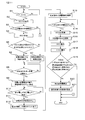
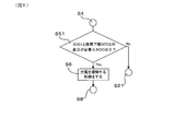
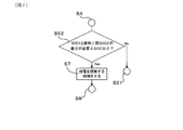
- FIG. 1 is a block diagram illustrating a configuration of a battery pack and a power supply system in Embodiment 1.
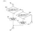
- FIG. 2 is a control flow diagram of the battery pack according to the first embodiment.
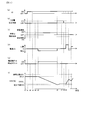
- FIG. 3 is a diagram illustrating a time chart in the battery pack according to the first embodiment.
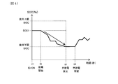
- FIG. 4 is a diagram illustrating the SOC change in the state where charging is regulated in the first embodiment.
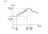
- FIG. 5 is a diagram illustrating a change in SOC in the state where discharge is regulated in the first embodiment.
- FIG. 6 is a control flow diagram in the battery pack according to the first modification.
- FIG. 7 is a control flow diagram of the battery pack according to the second modification.
- FIG. 8 is a control flow diagram in the battery pack according to the third modification.
- FIG. 9 is a control flow diagram in the battery pack according to the fourth modification.
- the battery pack 1 of the present embodiment includes a secondary battery 10, a voltage detection unit 11, a current detection unit 12, a charge state calculation unit 13, an integrated current amount calculation unit 14, a differential charge state calculation unit 15, A full charge capacity calculation unit 16 and a charge / discharge control unit 20 are provided.
- the voltage detection unit 11 detects the terminal voltage of the secondary battery 10.
- the charging state calculation unit 13 calculates the charging state SOC, that is, State Of Charge, based on the terminal voltage of the secondary battery 10.
- the current detection unit 12 detects the current that flows through the secondary battery 10.
- the charge / discharge control unit 20 controls charge / discharge of the secondary battery 10.
- the differential charge state calculation unit 15 includes a first charge state SOC1 calculated based on the first terminal voltage OCV1 detected by the voltage detection unit 11 at the first detection timing t2, and the voltage detection unit 11 at the second detection timing t7. A difference state of charge ⁇ SOC with respect to the second state of charge SOC2 calculated based on the detected second terminal voltage OCV2 is calculated.
- the integrated current amount calculation unit 14 calculates the integrated amount ⁇ Idt of the current detected by the current detection unit 12 in the target period T from the first detection timing t2 to the second detection timing t7.
- the full charge capacity calculation unit 16 is based on the difference charge state ⁇ SOC calculated by the difference charge state calculation unit 15 and the accumulated current amount ⁇ Idt calculated by the accumulated current amount calculation unit 14. Calculate the charge capacity.
- the charge / discharge control unit 20 is configured to regulate either charging or discharging of the secondary battery 10 during the target period t2 to t7.
- the battery pack 1 of the present embodiment is mounted on a vehicle, and as shown in FIG. 1, a vehicle rotating machine 101 is connected via a pack terminal 30 provided in the battery pack 1, and the pack terminal 31 is used.
- the electric load 102 and the Pb battery 103 are connected. Thereby, the power supply system 100 is configured.
- the secondary battery 10 provided in the battery pack 1 is connected to pack terminals 30 and 31 via switches 104 and 105. On / off of the charge / discharge restriction switch 104 and the charge / discharge prohibition switch 105 is controlled by the charge / discharge control unit 20 included in the control unit 2 of the battery pack 1.
- the kind of the secondary battery 10 is not limited, for example, it can be a non-aqueous secondary battery. In the present embodiment, a lithium ion battery is adopted as the secondary battery 10.
- a voltage detector 11 is connected to the secondary battery 10.
- a known voltage sensor can be used as the voltage detector 11, and the voltage detector 11 can detect the terminal voltage OCV of the secondary battery 10, that is, the Open Circuit Voltage, at a predetermined detection timing.
- the terminal voltage detected by the voltage detection unit 11 is stored in the OCV storage unit 41 included in the storage unit 4 of the battery pack 1.
- the charging state calculation unit 13 provided in the calculation unit 3 of the battery pack 1 charges the secondary battery 10 at the predetermined detection timing based on the terminal voltage at the predetermined detection timing stored in the OCV storage unit 41.
- a state SOC is calculated.
- the charging state calculation unit 13 stores in advance OCV-SOC conversion means based on the correspondence between the terminal voltage OCV and the charging state SOC in the secondary battery 10.
- the charging state calculation unit 13 can calculate the SOC at the predetermined detection timing from the OCV at the predetermined detection timing based on the OCV-SOC conversion means.
- the SOC calculated by the charging state calculation unit 13 is stored in the SOC storage unit 42 included in the storage unit 4.
- a current detector 12 is connected to the secondary battery 10.
- a known current sensor can be used as the current detection unit 12, and the current detection unit 12 can detect the current I flowing in the secondary battery 10 in a predetermined period.
- the current I detected by the current detection unit 12 is stored in the current amount storage unit 43 included in the storage unit 4.
- the accumulated current amount calculation unit 14 provided in the calculation unit 3 of the battery pack 1 integrates the secondary battery 10 in the predetermined period based on the current I that flows in the predetermined period stored in the current storage unit.
- the amount of current ⁇ Idt can be calculated.
- the integrated current amount ⁇ Idt calculated by the integrated current amount calculation unit 14 is stored in the ⁇ Idt storage unit 44 of the storage unit 4.
- the calculation unit 3 of the battery pack 1 includes a differential charge state calculation unit 15.
- the differential charge state calculation unit 15 calculates a differential charge state ⁇ SOC that is a difference between the SOC1 at the first detection timing and the SOC2 at the second detection timing, which is stored in the SOC storage unit 42.
- the calculated ⁇ SOC is stored in the ⁇ SOC storage unit 45 included in the storage unit 4.
- the full charge capacity calculation unit 16 included in the calculation unit 3 reads ⁇ Idt in a predetermined period stored in the ⁇ Idt storage unit 44 and ⁇ SOC in a predetermined period stored in the ⁇ SOC storage unit 45, and from these Calculate the full charge capacity.
- the calculation of the full charge capacity in the full charge capacity calculation unit 16 is calculated from the following formula 1, which is a relational expression of the full charge capacity, ⁇ Idt, and ⁇ SOC.
- Full charge capacity ( ⁇ Idt / ⁇ SOC) ⁇ 100 (Equation 1)
- FIG. The battery pack 1 includes a determination unit 5 that performs a determination described later based on the calculated value.
- the battery pack 1 has a charge / discharge control unit 20 in the control unit 2.
- the charge / discharge control unit 20 can regulate one of charging and discharging of the secondary battery 10 in a target period described later.
- the charge / discharge control unit 20 performs the regulation by turning on or off the switches 104 and 105 and permitting or regulating the generation of regenerative energy in the rotating machine 101.
- a charge / discharge prohibition switch 105 described later is turned on and the charge / discharge restriction switch 104 is turned off to supply power to the electric load 102 and the Pb battery 103. And the generation of regenerative energy by the rotating machine 101 is permitted.
- the regenerative energy output from the rotating machine 101 is input to the secondary battery 10, and the secondary battery 10 is charged.
- the generation of regenerative energy by the rotating machine 101 is regulated, and the electric load 102, the Pb battery 103, It is possible to supply power to the rotating machine 101. Thereby, the charge to the secondary battery 10 will be controlled.
- the charge / discharge control unit 20 can control the on / off of the charge / discharge prohibition switch 105 connected to the secondary battery 10. As a result, the charge / discharge control unit 20 can simultaneously inhibit both charging and discharging of the secondary battery 10.
- step S1 the ignition IG of the vehicle is turned ON.
- step S2 the timing when the IG is turned on is t1.
- step S2 the voltage detection unit 11 acquires the first terminal voltage OCV1 of the secondary battery 10 in step S2 shown in FIG.
- step S3 shown in FIG. 2 it is determined whether or not the polarization of the secondary battery 10 has been eliminated.
- the polarization of the secondary battery 10 is eliminated when one hour or more has elapsed since the end of the previous use of the secondary battery 10.
- the elapsed time can be measured using a counter (not shown) provided in the vehicle.
- the polarization may be forcibly eliminated by applying power to the secondary battery 10 or the like.
- step S3 If it is determined in step S3 that the polarization is not eliminated, the control is terminated. On the other hand, if it is determined in step S3 that the polarization has been eliminated, the charging state calculation unit 13 calculates the first charging state SOC1 based on OCV1 in step S4 shown in FIG. The timing for calculating the SOC1 is t3 shown in FIG. Note that step S3 may be performed before step S2 and step S4 may be performed after step S2.
- step S5 shown in FIG. 2 it is determined whether or not the absolute value of the difference between the SOC1 and the use lower limit SOC is equal to or greater than the required differential charge state, that is, the required ⁇ SOC.
- the necessary ⁇ SOC is a ⁇ SOC used for calculating the full charge capacity, and defines the size required to reduce the calculation error.
- the required ⁇ SOC includes the type of the secondary battery 10, the configuration of the power supply system 100, It can be set in advance as appropriate according to the usage environment of the battery pack 1 and the like.
- step S6 the charge / discharge control unit 20 selects to perform control to restrict charging. Then, at the timing t4 shown in FIG. 3C, the charging regulation of the charging / discharging regulation control is turned ON. Thereby, only the discharge of the secondary battery 10 is permitted. In addition, in the state where charge regulation is ON, the state where discharge is not performed is also permitted. That is, as shown in FIG. 4, there may be a state in which discharge does not occur and the SOC does not decrease and remains flat after t5 when the charging regulation is turned on.
- step S5 the charge / discharge control unit 20 performs control for regulating discharge in step S7. Choose that. Then, the discharge regulation of the charge / discharge regulation control is turned ON. Thereby, only charging of the secondary battery 10 is permitted. In the state where the discharge regulation is ON, a state where charging is not performed is also allowed. That is, as shown in FIG. 5, there may be a state in which charging does not occur after t5 when the discharge regulation is turned on and the SOC is leveled off without increasing.
- step S8 it is determined whether or not charging of the secondary battery 10 is started. In the present embodiment, it is determined whether regenerative energy from the rotating machine 101 is applied to the secondary battery 10.
- step S9 the integrated current amount calculation unit 14 starts integrating the amount of current and starts the counter 17.
- FIG. 3D shows the current when charging is restricted, and the timing at which the current starts to be detected is t5. Then, as shown in FIG. 3 (e), current amount integration and a counter are started at t5.
- step S10 shown in FIG. 2 it is determined whether or not the terminal voltage of the secondary battery 10 has reached a predetermined end voltage X.
- the end voltage X can be set as appropriate.
- the end voltage X is an OCV equivalent to the use lower limit SOC or the use upper limit SOC derived by the OCV-SOC conversion means based on the use lower limit SOC or the use upper limit SOC.
- the OCV corresponding to the use lower limit SOC is set as the end voltage X
- the discharge regulation is performed
- the OCV corresponding to the use upper limit SOC is set as the end voltage X.
- FIG. 3 (f) shows the SOC change when charging regulation is performed, and it is determined that the terminal voltage of the secondary battery 10 has reached the end voltage X when the SOC has reached the use lower limit SOC at t6. is doing.
- Step S10 shown in FIG. 2 when it is determined that the terminal voltage of the secondary battery 10 has not reached the end voltage X, the process returns to Step S10 again. If it is determined in step S10 that the terminal voltage of the secondary battery 10 has reached the end voltage X, both charging and discharging of the secondary battery 10 are prohibited in step S11. That is, as shown in FIG. 3B, the charge / discharge inhibition control is turned ON at t6. As a result, as shown in FIG. 3D, the current value is not detected at t6.
- step S12 shown in FIG. 2 as shown in FIG. 3E, the integration of the current amount and the counter 17 are finished at t6.
- step S13 shown in FIG. 2 at t6, as shown in FIG. 3C, when the charge regulation of step S6 is performed, the charge regulation is canceled, and when the discharge regulation of step S7 is performed, the discharge regulation is performed. Is released.
- step S14 shown in FIG. 2 it is determined whether or not the polarization of the secondary battery 10 has been eliminated.
- the voltage detection unit 11 detects the second terminal voltage OCV2 that is the terminal voltage of the secondary battery 10 in step S15 shown in FIG. To do. That is, in FIGS.
- t7 is set as the second detection timing t7.
- step S16 shown in FIG. 2 the charge / discharge prohibition is canceled. That is, as shown in FIG. 3B, the charge / discharge inhibition control is turned off at t8.
- step S17 shown in FIG. 2 the charge condition calculation part 13 acquires 2nd charge condition SOC2 based on OCV2. Further, in step S18, a difference ⁇ SOC between SOC1 and SOC2 is calculated. The acquisition of SOC2 and the calculation of ⁇ SOC may be performed after t7 in FIG.
- step S19 shown in FIG. 2 the accumulated time calculated by the accumulated time calculating unit 18 is equal to or greater than the predetermined value C, the voltage detecting unit 11 is abnormal, and the current detecting unit 12 is abnormal. It is determined whether or not any of the three determination items. If it is determined in step S19 that any of the above determination items is met, the control is terminated.
- the determination method of the presence or absence of abnormality in the voltage detection part 11 and the current detection part 12 is not specifically limited, For example, the detection value by the voltage detection part 11 and the current detection part 12 by the determination part 5 and the normal set in advance By comparing with the value range, when the detected value is within the normal value range, it can be determined that there is no abnormality, and when the detected value is not within the normal value range, it can be determined that there is an abnormality.
- step S20 the full charge capacity calculation unit 16 calculates the full charge capacity, and the control for calculating the full charge capacity ends. To do. Thereafter, in step S21, after t9 shown in FIG. 3, charging / discharging of the secondary battery 10 is started under normal control.
- the effect in the battery pack 1 of this embodiment is explained in full detail.
- charging / discharging of the secondary battery 10 is restricted to one during the target period t5 to t6 in which the accumulated current amount is calculated.
- the charge / discharge period required to obtain the predetermined ⁇ SOC can be shortened, so that the offset error of the current sensor accumulated in the integrated current amount ⁇ Idt can be reduced.
- the full charge capacity of the secondary battery 10 can be accurately calculated from the relational expression between ⁇ SOC and the integrated current amount ⁇ Idt.
- the second terminal voltage is detected as the second detection timing t7 when the differential charge state ⁇ SOC is equal to or greater than the required ⁇ SOC, and the charge / discharge control unit 20 detects the first charge state SOC1 and the required ⁇ SOC. Based on the above, it is configured to determine which of charging and discharging is to be regulated. As a result, ⁇ SOC can always be greater than or equal to the required ⁇ SOC, so that the value of ⁇ SOC can be increased. As a result, an error in calculating the full charge capacity can be reduced as compared with a case where ⁇ SOC is small.
- the charge / discharge control unit 20 has an absolute value of a difference between the first charge state SOC1 and the lower limit charge state in which the use of the secondary battery 10 is allowed, that is, the use lower limit SOC is greater than or equal to the required ⁇ SOC.
- the charging of the secondary battery 10 is restricted.
- ⁇ SOC that is greater than or equal to the required ⁇ SOC can be acquired in a short time, so that an error in calculating the full charge capacity can be reduced.
- the charge / discharge control unit 20 is configured such that the absolute value of the difference between the first charge state SOC1 and the upper limit charge state in which the use of the secondary battery 10 is allowed, that is, the use upper limit SOC is greater than or equal to the required ⁇ SOC.
- the secondary battery 10 is configured to be restricted from discharging. As a result, when the first state of charge SOC1 is relatively small, ⁇ SOC that is greater than or equal to the required ⁇ SOC can be acquired in a short time, and therefore an error in calculating the full charge capacity can be reduced.
- the secondary battery 10 is in an unloaded state and the polarization of the secondary battery 10 is eliminated. It has become. Thereby, since the detection error of the terminal voltage resulting from the polarization of the secondary battery 10 can be reduced, the error in calculating the full charge capacity can be reduced. In particular, in the present embodiment, since both the first detection timing t2 and the second detection timing t7 are in a no-load state and the polarization of the secondary battery 10 is eliminated, The error in calculating the full charge capacity can be further reduced. Note that the polarization of the secondary battery 10 does not necessarily have to be completely eliminated, and may be eliminated to the extent that required SOC accuracy can be ensured.
- the charge / discharge control unit 20 is configured to release the charge regulation and the discharge regulation at the second detection timing t7. As a result, normal charge / discharge control can be performed at an early stage, and no waste occurs. In this embodiment mounted on a vehicle, a reduction in fuel consumption of the vehicle can be suppressed.
- the current detection unit 12 has an integration time calculation unit 18 that calculates the integration time when the current is detected, and when the integration time calculated by the integration time calculation unit 18 is a predetermined value C or more, When it is determined that there is an abnormality in the detection unit 11 and / or when it is determined that there is an abnormality in the current detection unit 12, the charge / discharge control unit 20 does not regulate the above.
- the full charge capacity calculation unit 16 is configured not to calculate the full charge capacity. When the accumulated time at which the current is detected is equal to or greater than the predetermined value C, the offset error of the current sensor accumulated in the accumulated current amount ⁇ Idt becomes relatively large.
- the magnitude of the predetermined value C is not particularly limited, but in the present embodiment, a value in the range of 20 to 30 minutes is set.
- the battery pack 1, the rotating machine 101 that is electrically connected to the battery pack 1 and capable of generating power input to the battery pack 1, and the battery pack 1 are electrically connected.
- the power supply system 100 having such a configuration it is possible to efficiently use energy in the entire power supply system 100 by accurately calculating the full charge capacity of the battery pack 1.
- the power supply system 100 since the power supply system 100 is mounted on the vehicle, the fuel efficiency can be improved by efficiently using energy by the power supply system 100.
- the battery pack 1 capable of accurately calculating the full charge capacity of the secondary battery 10.
- step S5 when it is determined in step S5 that the absolute value of the difference between the SOC1 and the use lower limit SOC is equal to or greater than the required ⁇ SOC, the process proceeds to step S6. It was decided to proceed to S7.
- the charge / discharge control unit 20 may restrict one of charging and discharging and not the other as in Modification 1 and Modification 2 below.
- step S51 shown in FIG. 6 instead of going to step S5. If it is determined in step S51 that the absolute value of the difference between the SOC1 and the use lower limit SOC is equal to or greater than the required ⁇ SOC, the process proceeds to step S6 and subsequent steps as in the present embodiment, but the SOC1 and the use lower limit SOC If it is determined that the absolute value of the difference is not equal to or greater than the required ⁇ SOC, the process proceeds to step S21 shown in FIG. 2 instead of proceeding to step S7, and charging / discharging is started under normal control to calculate the full charge capacity. To finish the control. Therefore, in the first modification, the charge / discharge control unit 20 regulates charging, but does not regulate discharging.
- step S52 shown in FIG. 7 instead of going to step S5. If it is determined in step S52 that the absolute value of the difference between the SOC1 and the use upper limit SOC is equal to or larger than the required ⁇ SOC, the process proceeds to step S7 and subsequent steps shown in FIG. If it is determined that the absolute value of the difference from the use upper limit SOC is not equal to or greater than the required ⁇ SOC, the control is terminated. Therefore, in the second modification, the charge / discharge control unit 20 regulates discharging but does not regulate charging.
- the charge / discharge control unit 20 since the charge / discharge control unit 20 performs only discharge regulation or charge regulation, the charge / discharge control unit 20 has a configuration for implementing both charge regulation and discharge regulation. Compared to the above, the configuration of the charge / discharge control unit 20 can be simplified, and charge / discharge control is also facilitated.
- step S53 if it is determined that the absolute value of the difference between SOC1 and the lower limit of use SOC is greater than or equal to the required ⁇ SOC, the process proceeds to step S6 and subsequent steps as in the present embodiment. If it is determined that the absolute value of the difference is not greater than or equal to the required ⁇ SOC, the process proceeds to step S54.
- step S54 If it is determined in step S54 that the absolute value of the difference between the SOC1 and the use upper limit SOC is equal to or greater than the required ⁇ SOC, the process proceeds to step S7 and subsequent steps shown in FIG. When it is determined that the absolute value of the difference from the use upper limit SOC is not equal to or greater than the required ⁇ SOC, the process proceeds to step S21 shown in FIG. 2, and charging / discharging is started by normal control, and the control for calculating the full charge capacity is ended. .
- step S54 is performed, and if it is determined in step S54 that the absolute value of the difference between SOC1 and the use upper limit SOC is not greater than or equal to the required ⁇ SOC, step S53 is performed. If it is determined in step S53 that the absolute value of the difference between SOC1 and the lower limit of use SOC is not greater than or equal to the required ⁇ SOC, the process may proceed to step S21 shown in FIG.
- the control flow according to the third modification is suitable when the required ⁇ SOC is larger than the median value between the upper limit SOC and the lower limit SOC.
- the absolute value of the difference between the value of SOC1 from both the upper limit SOC and the lower limit SOC is less than the required ⁇ SOC.
- control is performed so as not to calculate the full charge capacity.
- ⁇ SOC is a relatively large value greater than or equal to the required ⁇ SOC
- the full charge capacity is calculated, so that ⁇ SOC is close to the full charge capacity and the error in calculating the full charge capacity is reduced. be able to.
- step S201 it is determined whether or not the first detection timing t2 corresponds to a specific timing.
- the process proceeds to step S2 and subsequent steps shown in FIG. 2, and after step S2 is performed as in the present embodiment, control for calculating the full charge capacity is performed.
- step S21 shown in FIG. 2, and normal charging / discharging is started to calculate the full charge capacity. End control.
- the calculation of the full charge capacity is performed when the first detection timing t2 corresponds to the specific timing, and is not performed in other cases. As a result, it is possible to prevent the opportunity for calculating the full charge capacity from being increased more than necessary, and to efficiently use energy.
- the setting of the specific timing can be appropriately adjusted according to the required calculation frequency of the full charge capacity.
- a state in which the number of arrivals of the trip period from on to off of the IG reaches a predetermined number can be set as the specific timing.
- the full charge capacity is calculated when it falls under a specific trip at a specific timing, and the full charge capacity is not calculated for other trips. This can prevent unnecessary fuel consumption reduction.
Abstract
A battery pack (1) of the present embodiment is provided with a secondary battery (10), a charge state calculation unit (13), an integrated current amount calculation unit (14), a differential charge state calculation unit (15), a full charge capacity calculation unit (16), and a charging and discharging control unit (20). The differential charge state calculation unit (15) calculates a differential state of charge (ΔSOC) between a first charge state (SOC1) at a first detection timing and a second charge state (SOC2) at a second detection timing. The integrated current amount calculation unit (14) calculates an integrated amount (∫Idt) of a current flowing to the secondary battery (10) in a target period from the first detection timing to the second detection timing. The full charging capacity calculation unit (16) calculates the full charge capacity of the secondary battery (10) on the basis of the differential charge state (ΔSOC) and the integrated current amount (∫Idt). The charging and discharging control unit (20) is configured to limit either charging or discharging of the secondary battery (10) in the target period.
Description
本出願は、2017年1月13日に出願された日本出願番号2017-3837号に基づくもので、ここにその記載内容を援用する。
This application is based on Japanese Patent Application No. 2017-3837 filed on January 13, 2017, the contents of which are incorporated herein by reference.
本開示は、電池パック及び電源システムに関する。
This disclosure relates to a battery pack and a power supply system.
従来、二次電池を有する電池パックにおいて、当該二次電池の満充電容量を算出する方法として、第1検出タイミングにおける二次電池の充電状態であるSOC1と、その後の第2検出タイミングにおける充電状態であるSOC2との差分ΔSOCと、第1検出タイミングから第2検出タイミングまでの二次電池における積算電流量∫Idtとの関係式を用いる方法が知られている。例えば、特許文献1には、車両に搭載された二次電池の制御装置の構成が開示されている。特許文献1に開示の構成では、車両のイグニッションオンからオフまでのトリップ期間において、第1トリップと第2トリップにおけるSOCの制御中心に差を付けることで第2トリップのトリップ前後で10%程度のΔSOCを算出し、当該ΔSOCと積算電流量∫Idtとから二次電池の満充電容量を算出している。
Conventionally, in a battery pack having a secondary battery, as a method for calculating the full charge capacity of the secondary battery, SOC1 which is the charged state of the secondary battery at the first detection timing, and the charged state at the subsequent second detection timing There is known a method using a relational expression of a difference ΔSOC with respect to SOC2 and the integrated current amount ∫Idt in the secondary battery from the first detection timing to the second detection timing. For example, Patent Document 1 discloses a configuration of a control device for a secondary battery mounted on a vehicle. In the configuration disclosed in Patent Document 1, in the trip period from the ignition on to the off of the vehicle, the difference in the control center of the SOC in the first trip and the second trip is about 10% before and after the trip of the second trip. ΔSOC is calculated, and the full charge capacity of the secondary battery is calculated from the ΔSOC and the integrated current amount ∫Idt.
特許文献1に開示の構成では、積算電流量∫Idtの算出に使用される電流センサはオフセット誤差を有する。そして、特許文献1に開示の構成では、測定対象となるトリップ期間中に二次電池の充電と放電の両方を行っている。そのため、電流センサによる電流値の測定期間が長くなっており、電流センサのオフセット誤差が積算電流量において積み上がっている。その結果、積算電流量に含まれる誤差が大きくなっているため、満充電容量を正確に算出するには改善の余地がある。
In the configuration disclosed in Patent Document 1, the current sensor used for calculating the integrated current amount ∫Idt has an offset error. In the configuration disclosed in Patent Document 1, both charging and discharging of the secondary battery are performed during the trip period to be measured. For this reason, the measurement period of the current value by the current sensor is long, and the offset error of the current sensor is accumulated in the integrated current amount. As a result, since the error included in the integrated current amount is large, there is room for improvement in accurately calculating the full charge capacity.
本開示は、二次電池を有する電池パックであって、当該二次電池の満充電容量を正確に算出することができる電池パックを提供しようとするものである。
The present disclosure is intended to provide a battery pack having a secondary battery and capable of accurately calculating the full charge capacity of the secondary battery.
本開示の一態様は、二次電池と、
該二次電池の端子電圧を検出する電圧検出部と、
上記電圧検出部が検出した端子電圧に基づいて上記二次電池の充電状態を算出する充電状態算出部と、
上記二次電池に流れた電流を検出する電流検出部と、
上記二次電池の充放電を制御する充放電制御部と、
上記電圧検出部が第1検出タイミングで検出した第1端子電圧に基づいて算出された第1充電状態と、上記電圧検出部が第2検出タイミングで検出した第2端子電圧に基づいて算出された第2充電状態との差分充電状態を算出する差分充電状態算出部と、
上記第1検出タイミングから上記第2検出タイミングまでの対象期間において、上記電流検出部で検出された電流の積算量を算出する積算電流量算出部と、
上記差分充電状態算出部により算出された差分充電状態と、上記積算電流量算出部により算出された積算電流量とに基づいて、上記二次電池の満充電容量を算出する満充電容量算出部と、
を備え、
上記充放電制御部は、上記対象期間において上記二次電池における充電及び放電のいずれか一方を規制するように構成されている、電池パックにある。 One embodiment of the present disclosure includes a secondary battery,
A voltage detector for detecting a terminal voltage of the secondary battery;
A charging state calculation unit that calculates a charging state of the secondary battery based on the terminal voltage detected by the voltage detection unit;
A current detector for detecting a current flowing in the secondary battery;
A charge / discharge control unit for controlling charge / discharge of the secondary battery;
The first charge state calculated based on the first terminal voltage detected at the first detection timing by the voltage detection unit, and the second terminal voltage detected by the voltage detection unit at the second detection timing. A differential charge state calculation unit for calculating a differential charge state from the second charge state;
An integrated current amount calculation unit that calculates an integrated amount of current detected by the current detection unit in a target period from the first detection timing to the second detection timing;
A full charge capacity calculation unit for calculating a full charge capacity of the secondary battery based on the differential charge state calculated by the differential charge state calculation unit and the integrated current amount calculated by the integrated current amount calculation unit; ,
With
The charge / discharge control unit is in a battery pack configured to regulate either charging or discharging of the secondary battery in the target period.
上記電池パックにおいては、積算電流量が算出される対象期間において、二次電池の充放電が一方に規制されている。これにより、所定の差分充電状態ΔSOCを取得するのに要する充放電の時間を短くすることができるため、積算電流量∫Idtに積み上がる電流センサのオフセット誤差を小さくすることができる。その結果、ΔSOCと∫Idtとの関係式から二次電池の満充電容量を正確に算出することができる。
In the battery pack, charging / discharging of the secondary battery is restricted to one side during the target period in which the accumulated current amount is calculated. As a result, the charge / discharge time required to obtain the predetermined differential charge state ΔSOC can be shortened, and therefore the offset error of the current sensor accumulated in the integrated current amount ∫Idt can be reduced. As a result, the full charge capacity of the secondary battery can be accurately calculated from the relational expression between ΔSOC and ∫Idt.
以上のごとく、本開示によれば、二次電池を有し、当該二次電池の満充電容量を正確に算出することができる電池パックを提供することができる。
As described above, according to the present disclosure, it is possible to provide a battery pack that has a secondary battery and can accurately calculate the full charge capacity of the secondary battery.
なお、請求の範囲に記載した括弧内の符号は、後述する実施形態に記載の具体的手段との対応関係を示すものであり、本開示の技術的範囲を限定するものではない。
In addition, the code | symbol in the parenthesis described in the claim shows the correspondence with the specific means as described in embodiment mentioned later, and does not limit the technical scope of this indication.
本開示についての上記目的およびその他の目的、特徴や利点は、添付の図を参照しながら下記の詳細な記述により、より明確になる。その図は、
図1は、実施形態1における、電池パックと電源システムの構成を示すブロック図であり、
図2は、実施形態1における、電池パックにおける制御フロー図であり、
図3は、実施形態1における、電池パックにおけるタイムチャートを示す図であり、
図4は、実施形態1における、充電が規制された状態でのSOC変化を表す図であり、
図5は、実施形態1における、放電が規制された状態でのSOC変化を表す図であり、
図6は、変形形態1における、電池パックにおける制御フロー図であり、
図7は、変形形態2における、電池パックにおける制御フロー図であり、
図8は、変形形態3における、電池パックにおける制御フロー図であり、
図9は、変形形態4における、電池パックにおける制御フロー図である。
The above and other objects, features, and advantages of the present disclosure will become more apparent from the following detailed description with reference to the accompanying drawings. The figure
FIG. 1 is a block diagram illustrating a configuration of a battery pack and a power supply system in Embodiment 1. FIG. 2 is a control flow diagram of the battery pack according to the first embodiment. FIG. 3 is a diagram illustrating a time chart in the battery pack according to the first embodiment. FIG. 4 is a diagram illustrating the SOC change in the state where charging is regulated in the first embodiment. FIG. 5 is a diagram illustrating a change in SOC in the state where discharge is regulated in the first embodiment. FIG. 6 is a control flow diagram in the battery pack according to the first modification. FIG. 7 is a control flow diagram of the battery pack according to the second modification. FIG. 8 is a control flow diagram in the battery pack according to the third modification. FIG. 9 is a control flow diagram in the battery pack according to the fourth modification.
(実施形態1)
上記電池パックの実施形態について、図1~図5を用いて説明する。
本実施形態の電池パック1は、図1に示すように二次電池10、電圧検出部11、電流検出部12、充電状態算出部13、積算電流量算出部14、差分充電状態算出部15、満充電容量算出部16、充放電制御部20を備える。 (Embodiment 1)
An embodiment of the battery pack will be described with reference to FIGS.
As shown in FIG. 1, thebattery pack 1 of the present embodiment includes a secondary battery 10, a voltage detection unit 11, a current detection unit 12, a charge state calculation unit 13, an integrated current amount calculation unit 14, a differential charge state calculation unit 15, A full charge capacity calculation unit 16 and a charge / discharge control unit 20 are provided.
上記電池パックの実施形態について、図1~図5を用いて説明する。
本実施形態の電池パック1は、図1に示すように二次電池10、電圧検出部11、電流検出部12、充電状態算出部13、積算電流量算出部14、差分充電状態算出部15、満充電容量算出部16、充放電制御部20を備える。 (Embodiment 1)
An embodiment of the battery pack will be described with reference to FIGS.
As shown in FIG. 1, the
電圧検出部11は、二次電池10の端子電圧を検出する。
充電状態算出部13は、二次電池10の端子電圧に基づいて充電状態SOC、すなわちState Of Chargeを算出する。
電流検出部12は、二次電池10に流れた電流を検出する。
充放電制御部20は、二次電池10の充放電を制御する。
差分充電状態算出部15は、電圧検出部11が第1検出タイミングt2で検出した第1端子電圧OCV1に基づいて算出された第1充電状態SOC1と、電圧検出部11が第2検出タイミングt7で検出した第2端子電圧OCV2に基づいて算出された第2充電状態SOC2との差分充電状態ΔSOCを算出する。 Thevoltage detection unit 11 detects the terminal voltage of the secondary battery 10.
The chargingstate calculation unit 13 calculates the charging state SOC, that is, State Of Charge, based on the terminal voltage of the secondary battery 10.
Thecurrent detection unit 12 detects the current that flows through the secondary battery 10.
The charge /discharge control unit 20 controls charge / discharge of the secondary battery 10.
The differential chargestate calculation unit 15 includes a first charge state SOC1 calculated based on the first terminal voltage OCV1 detected by the voltage detection unit 11 at the first detection timing t2, and the voltage detection unit 11 at the second detection timing t7. A difference state of charge ΔSOC with respect to the second state of charge SOC2 calculated based on the detected second terminal voltage OCV2 is calculated.
充電状態算出部13は、二次電池10の端子電圧に基づいて充電状態SOC、すなわちState Of Chargeを算出する。
電流検出部12は、二次電池10に流れた電流を検出する。
充放電制御部20は、二次電池10の充放電を制御する。
差分充電状態算出部15は、電圧検出部11が第1検出タイミングt2で検出した第1端子電圧OCV1に基づいて算出された第1充電状態SOC1と、電圧検出部11が第2検出タイミングt7で検出した第2端子電圧OCV2に基づいて算出された第2充電状態SOC2との差分充電状態ΔSOCを算出する。 The
The charging
The
The charge /
The differential charge
積算電流量算出部14は、第1検出タイミングt2から第2検出タイミングt7までの対象期間Tにおいて、電流検出部12で検出された電流の積算量∫Idtを算出する。
満充電容量算出部16は、差分充電状態算出部15により算出された差分充電状態ΔSOCと、積算電流量算出部14により算出された積算電流量∫Idtとに基づいて、二次電池10の満充電容量を算出する。
そして、充放電制御部20は、対象期間t2~t7において、二次電池10における充電及び放電のいずれか一方を規制するように構成されている。 The integrated currentamount calculation unit 14 calculates the integrated amount ∫Idt of the current detected by the current detection unit 12 in the target period T from the first detection timing t2 to the second detection timing t7.
The full chargecapacity calculation unit 16 is based on the difference charge state ΔSOC calculated by the difference charge state calculation unit 15 and the accumulated current amount ∫Idt calculated by the accumulated current amount calculation unit 14. Calculate the charge capacity.
The charge /discharge control unit 20 is configured to regulate either charging or discharging of the secondary battery 10 during the target period t2 to t7.
満充電容量算出部16は、差分充電状態算出部15により算出された差分充電状態ΔSOCと、積算電流量算出部14により算出された積算電流量∫Idtとに基づいて、二次電池10の満充電容量を算出する。
そして、充放電制御部20は、対象期間t2~t7において、二次電池10における充電及び放電のいずれか一方を規制するように構成されている。 The integrated current
The full charge
The charge /
以下、本実施形態の電池パック1について、詳述する。
本実施形態では電池パック1は車両に搭載され、図1に示すように、電池パック1に設けられたパック端子30を介して、車両の回転機101が接続されており、パック端子31を介して電気負荷102、Pb電池103が接続されている。これにより、電源システム100が構成されている。 Hereinafter, thebattery pack 1 of the present embodiment will be described in detail.
In the present embodiment, thebattery pack 1 is mounted on a vehicle, and as shown in FIG. 1, a vehicle rotating machine 101 is connected via a pack terminal 30 provided in the battery pack 1, and the pack terminal 31 is used. The electric load 102 and the Pb battery 103 are connected. Thereby, the power supply system 100 is configured.
本実施形態では電池パック1は車両に搭載され、図1に示すように、電池パック1に設けられたパック端子30を介して、車両の回転機101が接続されており、パック端子31を介して電気負荷102、Pb電池103が接続されている。これにより、電源システム100が構成されている。 Hereinafter, the
In the present embodiment, the
図1に示すように、電池パック1に備えられる二次電池10は、スイッチ104、105を介してパック端子30、31に接続されている。充放電規制スイッチ104、充放電禁止スイッチ105におけるオンオフは、電池パック1の制御部2が有する充放電制御部20により制御される。二次電池10の種類は限定されないが、例えば、非水系二次電池とすることができ、本実施形態では、二次電池10としてリチウムイオン電池を採用している。
As shown in FIG. 1, the secondary battery 10 provided in the battery pack 1 is connected to pack terminals 30 and 31 via switches 104 and 105. On / off of the charge / discharge restriction switch 104 and the charge / discharge prohibition switch 105 is controlled by the charge / discharge control unit 20 included in the control unit 2 of the battery pack 1. Although the kind of the secondary battery 10 is not limited, for example, it can be a non-aqueous secondary battery. In the present embodiment, a lithium ion battery is adopted as the secondary battery 10.
図1に示すように、二次電池10には電圧検出部11が接続されている。電圧検出部11として公知の電圧センサを用いることができ、電圧検出部11によって所定の検出タイミングで当該二次電池10の端子電圧OCV、すなわちOpen Circuit Voltageを検出することができる。電圧検出部11によって検出された端子電圧は、電池パック1の記憶部4が有するOCV記憶部41に記憶される。
As shown in FIG. 1, a voltage detector 11 is connected to the secondary battery 10. A known voltage sensor can be used as the voltage detector 11, and the voltage detector 11 can detect the terminal voltage OCV of the secondary battery 10, that is, the Open Circuit Voltage, at a predetermined detection timing. The terminal voltage detected by the voltage detection unit 11 is stored in the OCV storage unit 41 included in the storage unit 4 of the battery pack 1.
そして、電池パック1の演算部3に備えられた充電状態算出部13により、OCV記憶部41に記憶された所定検出タイミングでの端子電圧に基づいて、所定検出タイミングでの二次電池10の充電状態SOCが算出される。充電状態算出部13には二次電池10における端子電圧OCVと充電状態SOCとの対応関係に基づいたOCV-SOC変換手段が予め記憶されている。充電状態算出部13はOCV-SOC変換手段に基づいて、所定検出タイミングでのOCVから所定検出タイミングでのSOCを算出することができる。充電状態算出部13により算出されたSOCは記憶部4が有するSOC記憶部42に記憶される。
Then, the charging state calculation unit 13 provided in the calculation unit 3 of the battery pack 1 charges the secondary battery 10 at the predetermined detection timing based on the terminal voltage at the predetermined detection timing stored in the OCV storage unit 41. A state SOC is calculated. The charging state calculation unit 13 stores in advance OCV-SOC conversion means based on the correspondence between the terminal voltage OCV and the charging state SOC in the secondary battery 10. The charging state calculation unit 13 can calculate the SOC at the predetermined detection timing from the OCV at the predetermined detection timing based on the OCV-SOC conversion means. The SOC calculated by the charging state calculation unit 13 is stored in the SOC storage unit 42 included in the storage unit 4.
図1に示すように、二次電池10には電流検出部12が接続されている。電流検出部12として公知の電流センサを用いることができ、電流検出部12によって所定期間において二次電池10に流れた電流Iを検出することができる。電流検出部12によって検出された電流Iは、記憶部4が有する電流量記憶部43に記憶される。
As shown in FIG. 1, a current detector 12 is connected to the secondary battery 10. A known current sensor can be used as the current detection unit 12, and the current detection unit 12 can detect the current I flowing in the secondary battery 10 in a predetermined period. The current I detected by the current detection unit 12 is stored in the current amount storage unit 43 included in the storage unit 4.
そして、電池パック1の演算部3に備えられた積算電流量算出部14により、電流記憶部に記憶された所定期間に流れた電流Iに基づいて、所定期間における二次電池10に流れた積算電流量∫Idtを算出することができる。積算電流量算出部14によって算出された積算電流量∫Idtは記憶部4が有する∫Idt記憶部44に記憶される。
Then, the accumulated current amount calculation unit 14 provided in the calculation unit 3 of the battery pack 1 integrates the secondary battery 10 in the predetermined period based on the current I that flows in the predetermined period stored in the current storage unit. The amount of current ∫Idt can be calculated. The integrated current amount ∫Idt calculated by the integrated current amount calculation unit 14 is stored in the ∫Idt storage unit 44 of the storage unit 4.
図1に示すように、電池パック1の演算部3には差分充電状態算出部15が備えられている。差分充電状態算出部15は、SOC記憶部42に記憶された、第1検出タイミングにおけるSOC1と第2検出タイミングにおけるSOC2との差分である差分充電状態ΔSOCを算出する。そして、算出されたΔSOCは記憶部4が有するΔSOC記憶部45に記憶される。
As shown in FIG. 1, the calculation unit 3 of the battery pack 1 includes a differential charge state calculation unit 15. The differential charge state calculation unit 15 calculates a differential charge state ΔSOC that is a difference between the SOC1 at the first detection timing and the SOC2 at the second detection timing, which is stored in the SOC storage unit 42. The calculated ΔSOC is stored in the ΔSOC storage unit 45 included in the storage unit 4.
そして、演算部3が有する満充電容量算出部16は、∫Idt記憶部44に記憶された所定期間における∫Idtと、ΔSOC記憶部45に記憶された所定期間におけるΔSOCとを読み出すとともに、これらから満充電容量を算出する。満充電容量算出部16における満充電容量の算出は、満充電容量と∫Idtと及びΔSOCとの関係式である以下の式1から算出される。
満充電容量=(∫Idt/ΔSOC)×100 (式1) The full chargecapacity calculation unit 16 included in the calculation unit 3 reads ∫Idt in a predetermined period stored in the ∫Idt storage unit 44 and ΔSOC in a predetermined period stored in the ΔSOC storage unit 45, and from these Calculate the full charge capacity. The calculation of the full charge capacity in the full charge capacity calculation unit 16 is calculated from the following formula 1, which is a relational expression of the full charge capacity, ∫Idt, and ΔSOC.
Full charge capacity = (∫Idt / ΔSOC) × 100 (Equation 1)
満充電容量=(∫Idt/ΔSOC)×100 (式1) The full charge
Full charge capacity = (∫Idt / ΔSOC) × 100 (Equation 1)
また、本実施形態では、図1に示すように、二次電池10に電流が流れた時間を計測するためのカウンタ17と、積算電流量算出部14の算出対象となる積算時間を算出する積算時間算出部18と、積算時間算出部18の算出結果を記憶する積算時間記憶部46とを有する。そして、電池パック1には、上記算出された値に基づいて後述の判定を行う判定部5が備えられている。
In the present embodiment, as shown in FIG. 1, the counter 17 for measuring the time when the current flows in the secondary battery 10 and the integration for calculating the integration time to be calculated by the integration current amount calculation unit 14. It has the time calculation part 18 and the integration time memory | storage part 46 which memorize | stores the calculation result of the integration time calculation part 18. FIG. The battery pack 1 includes a determination unit 5 that performs a determination described later based on the calculated value.
図1に示すように、電池パック1は制御部2に充放電制御部20を有する。充放電制御部20は後述の対象期間において、二次電池10の充電及び放電の一方を規制することができる。本実施形態では、上述のように、充放電制御部20はスイッチ104、105をオンまたはオフすること及び回転機101における回生エネルギーの発生を許可または規制することにより、上記規制を行う。具体的には、二次電池10の放電を規制する場合には、後述する充放電禁止スイッチ105をオンにするとともに充放電規制スイッチ104をオフにして電気負荷102やPb電池103への電力供給を遮断し、回転機101による回生エネルギーの発生を許可する。これにより、回転機101から出力される回生エネルギーが二次電池10に入力されて二次電池10の充電が行われる。一方、二次電池10の充電を規制する場合には、回転機101による回生エネルギーの発生を規制し、充放電禁止スイッチ105及び充放電規制スイッチ104をオンにして電気負荷102、Pb電池103や回転機101への電力供給を可能とする。これにより、二次電池10への充電は規制されることとなる。
As shown in FIG. 1, the battery pack 1 has a charge / discharge control unit 20 in the control unit 2. The charge / discharge control unit 20 can regulate one of charging and discharging of the secondary battery 10 in a target period described later. In the present embodiment, as described above, the charge / discharge control unit 20 performs the regulation by turning on or off the switches 104 and 105 and permitting or regulating the generation of regenerative energy in the rotating machine 101. Specifically, when the discharge of the secondary battery 10 is regulated, a charge / discharge prohibition switch 105 described later is turned on and the charge / discharge restriction switch 104 is turned off to supply power to the electric load 102 and the Pb battery 103. And the generation of regenerative energy by the rotating machine 101 is permitted. Thereby, the regenerative energy output from the rotating machine 101 is input to the secondary battery 10, and the secondary battery 10 is charged. On the other hand, when charging of the secondary battery 10 is regulated, the generation of regenerative energy by the rotating machine 101 is regulated, and the electric load 102, the Pb battery 103, It is possible to supply power to the rotating machine 101. Thereby, the charge to the secondary battery 10 will be controlled.
本実施形態では、図1に示すように、充放電制御部20は、二次電池10に接続された充放電禁止スイッチ105のオンオフを制御することができる。これにより、充放電制御部20は、二次電池10における充電及び放電の両方を同時禁止することができるようになっている。
In this embodiment, as shown in FIG. 1, the charge / discharge control unit 20 can control the on / off of the charge / discharge prohibition switch 105 connected to the secondary battery 10. As a result, the charge / discharge control unit 20 can simultaneously inhibit both charging and discharging of the secondary battery 10.
次に、電池パック1における二次電池10の満充電容量を算出するための制御について、図2及び図3を用いて説明する。
図2に示すように、まず、ステップS1において、車両のイグニッションIGをONにする。図3(a)に示すように、IGがONとなるタイミングをt1とする。その後、第1検出タイミングt2が到来すると、図2に示すステップS2において、電圧検出部11により二次電池10の第1端子電圧OCV1を取得する。 Next, control for calculating the full charge capacity of thesecondary battery 10 in the battery pack 1 will be described with reference to FIGS. 2 and 3.
As shown in FIG. 2, first, in step S1, the ignition IG of the vehicle is turned ON. As shown in FIG. 3A, the timing when the IG is turned on is t1. Thereafter, when the first detection timing t2 arrives, thevoltage detection unit 11 acquires the first terminal voltage OCV1 of the secondary battery 10 in step S2 shown in FIG.
図2に示すように、まず、ステップS1において、車両のイグニッションIGをONにする。図3(a)に示すように、IGがONとなるタイミングをt1とする。その後、第1検出タイミングt2が到来すると、図2に示すステップS2において、電圧検出部11により二次電池10の第1端子電圧OCV1を取得する。 Next, control for calculating the full charge capacity of the
As shown in FIG. 2, first, in step S1, the ignition IG of the vehicle is turned ON. As shown in FIG. 3A, the timing when the IG is turned on is t1. Thereafter, when the first detection timing t2 arrives, the
次に、図2に示すステップS3において、二次電池10の分極が解消した状態であるか判定する。本実施形態では、二次電池10の前回の使用終了時から1時間以上経過している場合に二次電池10の分極が解消した状態であると判定する。当該経過時間の計測は、車両に備えられた図示しないカウンタを用いて行うことができる。なお、二次電池10に電力を印加する等して強制的に分極を解消するようにしてもよい。
Next, in step S3 shown in FIG. 2, it is determined whether or not the polarization of the secondary battery 10 has been eliminated. In the present embodiment, it is determined that the polarization of the secondary battery 10 is eliminated when one hour or more has elapsed since the end of the previous use of the secondary battery 10. The elapsed time can be measured using a counter (not shown) provided in the vehicle. The polarization may be forcibly eliminated by applying power to the secondary battery 10 or the like.
そして、ステップS3において分極が解消した状態ではないと判定した場合は、当該制御を終了する。一方、ステップS3において分極が解消した状態であると判定した場合は、図2に示すステップS4において、充電状態算出部13によりOCV1に基づいて第1充電状態SOC1を算出する。SOC1を算出するタイミングを図2に示すt3とする。なお、ステップS3はステップS2の前に実施するとともにステップS2の後にステップS4を実施するようにしてもよい。
If it is determined in step S3 that the polarization is not eliminated, the control is terminated. On the other hand, if it is determined in step S3 that the polarization has been eliminated, the charging state calculation unit 13 calculates the first charging state SOC1 based on OCV1 in step S4 shown in FIG. The timing for calculating the SOC1 is t3 shown in FIG. Note that step S3 may be performed before step S2 and step S4 may be performed after step S2.
その後、図2に示すステップS5において、SOC1と使用下限SOCとの差分の絶対値が、必要差分充電状態、すなわち必要ΔSOC以上か否か判定する。必要ΔSOCは、満充電容量の算出に利用されるΔSOCとして、算出誤差を小さくするために必要とされる大きさを規定するものであって、二次電池10の種類、電源システム100の構成、電池パック1の使用環境等に応じて、適宜予め設定することができる。ステップS5において、SOC1と使用下限SOCとの差分の絶対値が必要ΔSOC以上であると判定した場合は、ステップS6において、充放電制御部20において、充電を規制する制御を行うことを選択する。そして、図3(c)に示すタイミングt4において、充放電規制制御の充電規制をONにする。これにより、二次電池10の放電のみが許可される。なお、充電規制がONの状態では、放電が行われていない状態も許容される。すなわち、図4に示すように、充電規制がONとなったt5以降に、放電が生じず、SOCが低下せずに横ばいとなる状態があってもよい。
After that, in step S5 shown in FIG. 2, it is determined whether or not the absolute value of the difference between the SOC1 and the use lower limit SOC is equal to or greater than the required differential charge state, that is, the required ΔSOC. The necessary ΔSOC is a ΔSOC used for calculating the full charge capacity, and defines the size required to reduce the calculation error. The required ΔSOC includes the type of the secondary battery 10, the configuration of the power supply system 100, It can be set in advance as appropriate according to the usage environment of the battery pack 1 and the like. If it is determined in step S5 that the absolute value of the difference between the SOC1 and the lower limit of use SOC is greater than or equal to the required ΔSOC, in step S6, the charge / discharge control unit 20 selects to perform control to restrict charging. Then, at the timing t4 shown in FIG. 3C, the charging regulation of the charging / discharging regulation control is turned ON. Thereby, only the discharge of the secondary battery 10 is permitted. In addition, in the state where charge regulation is ON, the state where discharge is not performed is also permitted. That is, as shown in FIG. 4, there may be a state in which discharge does not occur and the SOC does not decrease and remains flat after t5 when the charging regulation is turned on.
一方、図2に示すステップS5において、SOC1と使用下限SOCとの差分の絶対値が必要ΔSOC以上でないと判定した場合は、ステップS7において、充放電制御部20において、放電を規制する制御を行うことを選択する。そして、充放電規制制御の放電規制をONにする。これにより、二次電池10の充電のみが許可される。なお、放電規制がONの状態では、充電が行われていない状態も許容される。すなわち、図5に示すように、放電規制がONとなったt5以降に充電が生じず、SOCが上昇せずに横ばいとなる状態があってもよい。
On the other hand, if it is determined in step S5 shown in FIG. 2 that the absolute value of the difference between the SOC1 and the lower limit of use SOC is not equal to or greater than the required ΔSOC, the charge / discharge control unit 20 performs control for regulating discharge in step S7. Choose that. Then, the discharge regulation of the charge / discharge regulation control is turned ON. Thereby, only charging of the secondary battery 10 is permitted. In the state where the discharge regulation is ON, a state where charging is not performed is also allowed. That is, as shown in FIG. 5, there may be a state in which charging does not occur after t5 when the discharge regulation is turned on and the SOC is leveled off without increasing.
その後、ステップS8において、二次電池10の充電が開始されたか否かを判定する。本実施形態では、回転機101による回生エネルギーが二次電池10に印加されたか否かを判定する。ステップS8において二次電池10の充電が開始されたと判定した場合、すなわち、図3(d)に示すようにt5において、電流検出部12により二次電池10に流れる電流が検出された場合には、図2に示すステップS9において、積算電流量算出部14により電流量の積算を開始し、カウンタ17をスタートさせる。図3(d)では充電が規制される場合の電流を表しており、電流が検出され始めたタイミングをt5とする。そして、図3(e)に示すようにt5において電流量の積算とカウンタを開始する。
Thereafter, in step S8, it is determined whether or not charging of the secondary battery 10 is started. In the present embodiment, it is determined whether regenerative energy from the rotating machine 101 is applied to the secondary battery 10. When it is determined in step S8 that charging of the secondary battery 10 has started, that is, when the current flowing through the secondary battery 10 is detected by the current detection unit 12 at t5 as shown in FIG. In step S9 shown in FIG. 2, the integrated current amount calculation unit 14 starts integrating the amount of current and starts the counter 17. FIG. 3D shows the current when charging is restricted, and the timing at which the current starts to be detected is t5. Then, as shown in FIG. 3 (e), current amount integration and a counter are started at t5.
そして、図2に示すステップS10において、二次電池10の端子電圧が所定の終了電圧Xに到達したか否か判定する。終了電圧Xは適宜設定することができるが、本実施形態では、使用下限SOC又は使用上限SOCに基づいて、OCV-SOC変換手段により導き出される使用下限SOC又は使用上限SOC相当のOCVとしている。そして、充電規制を行った場合は使用下限SOC相当のOCVを終了電圧Xとし、放電規制を行った場合は使用上限SOC相当のOCVを終了電圧Xとする。図3(f)では、充電規制を行った場合のSOC変化を示しており、t6においてSOCが使用下限SOCに到達したときを、二次電池10の端子電圧が終了電圧Xに到達したと判定している。
Then, in step S10 shown in FIG. 2, it is determined whether or not the terminal voltage of the secondary battery 10 has reached a predetermined end voltage X. The end voltage X can be set as appropriate. In this embodiment, the end voltage X is an OCV equivalent to the use lower limit SOC or the use upper limit SOC derived by the OCV-SOC conversion means based on the use lower limit SOC or the use upper limit SOC. When the charge regulation is performed, the OCV corresponding to the use lower limit SOC is set as the end voltage X, and when the discharge regulation is performed, the OCV corresponding to the use upper limit SOC is set as the end voltage X. FIG. 3 (f) shows the SOC change when charging regulation is performed, and it is determined that the terminal voltage of the secondary battery 10 has reached the end voltage X when the SOC has reached the use lower limit SOC at t6. is doing.
図2に示すステップS10において、二次電池10の端子電圧が終了電圧Xに到達していないと判定した場合は、再度ステップS10に戻る。そして、ステップS10において、二次電池10の端子電圧が終了電圧Xに到達したと判定した場合は、ステップS11において、二次電池10の充電及び放電の両方を禁止する。すなわち、図3(b)に示すように、t6において充放電禁止制御をONとする。これにより、図3(d)に示すように、t6において電流値が検出されなくなる。
In Step S10 shown in FIG. 2, when it is determined that the terminal voltage of the secondary battery 10 has not reached the end voltage X, the process returns to Step S10 again. If it is determined in step S10 that the terminal voltage of the secondary battery 10 has reached the end voltage X, both charging and discharging of the secondary battery 10 are prohibited in step S11. That is, as shown in FIG. 3B, the charge / discharge inhibition control is turned ON at t6. As a result, as shown in FIG. 3D, the current value is not detected at t6.
そして、図2に示すステップS12において、図3(e)に示すようにt6で電流量の積算及びカウンタ17を終了する。これとともに図2に示すステップS13において、図3(c)に示すようにt6で、ステップS6の充電規制を行った場合は充電規制を解除し、ステップS7の放電規制を行った場合は放電規制を解除する。
Then, in step S12 shown in FIG. 2, as shown in FIG. 3E, the integration of the current amount and the counter 17 are finished at t6. At the same time, in step S13 shown in FIG. 2, at t6, as shown in FIG. 3C, when the charge regulation of step S6 is performed, the charge regulation is canceled, and when the discharge regulation of step S7 is performed, the discharge regulation is performed. Is released.
その後、図2に示すステップS14において、二次電池10の分極が解消した否か判定する。本実施形態では、ステップS11における二次電池10の充放電の禁止開始から5分以上経過している場合に二次電池10の分極が解消した状態であると判定する。ステップS14において、二次電池10の分極が解消していないと判断した場合は、再度ステップS14に戻る。一方、ステップS14において、二次電池10の分極が解消したと判断した場合は、図2に示すステップS15において、電圧検出部11により二次電池10の端子電圧である第2端子電圧OCV2を検出する。すなわち、図3(a)~(f)において、t7を第2検出タイミングt7とする。そして、図2に示すステップS16において、充放電の禁止を解除する。すなわち、図3(b)に示すようにt8で充放電の禁止制御をOFFにする。
Thereafter, in step S14 shown in FIG. 2, it is determined whether or not the polarization of the secondary battery 10 has been eliminated. In the present embodiment, it is determined that the polarization of the secondary battery 10 has been eliminated when 5 minutes or more have elapsed since the start of the prohibition of charging / discharging of the secondary battery 10 in step S11. If it is determined in step S14 that the polarization of the secondary battery 10 has not been eliminated, the process returns to step S14 again. On the other hand, if it is determined in step S14 that the polarization of the secondary battery 10 has been eliminated, the voltage detection unit 11 detects the second terminal voltage OCV2 that is the terminal voltage of the secondary battery 10 in step S15 shown in FIG. To do. That is, in FIGS. 3A to 3F, t7 is set as the second detection timing t7. In step S16 shown in FIG. 2, the charge / discharge prohibition is canceled. That is, as shown in FIG. 3B, the charge / discharge inhibition control is turned off at t8.
そして、図2に示すステップS17において、充電状態算出部13によりOCV2に基づいて第2充電状態SOC2を取得する。さらにステップS18において、SOC1とSOC2との差分ΔSOCを算出する。なお、SOC2の取得及びΔSOCの算出は、図3(f)におけるt7以降であればよい。
And in step S17 shown in FIG. 2, the charge condition calculation part 13 acquires 2nd charge condition SOC2 based on OCV2. Further, in step S18, a difference ΔSOC between SOC1 and SOC2 is calculated. The acquisition of SOC2 and the calculation of ΔSOC may be performed after t7 in FIG.
その後、図2に示すステップS19において、積算時間算出部18により算出された積算時間が所定値C以上であること、電圧検出部11に異常があること、及び電流検出部12に異常があることの3つの判定事項のいずれかに該当するか否か判定する。ステップS19において、上記判定事項のいずれかに該当すると判定された場合は、制御を終了する。なお、電圧検出部11及び電流検出部12における異常の有無の判定方法は特に限定されないが、例えば、判定部5により、電圧検出部11及び電流検出部12による検出値と、予め設定された正常値範囲とを比較して、検出値が当該正常値範囲内である場合は異常がないと判定し、当該正常値範囲内でない場合は異常があると判定することができる。
Thereafter, in step S19 shown in FIG. 2, the accumulated time calculated by the accumulated time calculating unit 18 is equal to or greater than the predetermined value C, the voltage detecting unit 11 is abnormal, and the current detecting unit 12 is abnormal. It is determined whether or not any of the three determination items. If it is determined in step S19 that any of the above determination items is met, the control is terminated. In addition, although the determination method of the presence or absence of abnormality in the voltage detection part 11 and the current detection part 12 is not specifically limited, For example, the detection value by the voltage detection part 11 and the current detection part 12 by the determination part 5 and the normal set in advance By comparing with the value range, when the detected value is within the normal value range, it can be determined that there is no abnormality, and when the detected value is not within the normal value range, it can be determined that there is an abnormality.
一方、ステップS19において、上記判定事項のいずれにも該当しないと判定された場合は、ステップS20において、満充電容量算出部16により満充電容量を算出し、満充電容量の算出を行う制御が終了する。その後は、ステップS21において、図3に示すt9以降は、通常制御で二次電池10の充放電を開始する。
On the other hand, if it is determined in step S19 that none of the above determination items is applicable, in step S20, the full charge capacity calculation unit 16 calculates the full charge capacity, and the control for calculating the full charge capacity ends. To do. Thereafter, in step S21, after t9 shown in FIG. 3, charging / discharging of the secondary battery 10 is started under normal control.
次に、本実施形態の電池パック1における作用効果について、詳述する。
電池パック1では、積算電流量が算出される対象期間t5~t6において、二次電池10の充放電が一方に規制されている。これにより、所定のΔSOCを取得するのに要する充放電の期間を短くすることができるため、積算電流量∫Idtに積み上がる電流センサのオフセット誤差を小さくすることができる。その結果、ΔSOCと積算電流量∫Idtとの関係式から二次電池10の満充電容量を正確に算出することができる。 Next, the effect in thebattery pack 1 of this embodiment is explained in full detail.
In thebattery pack 1, charging / discharging of the secondary battery 10 is restricted to one during the target period t5 to t6 in which the accumulated current amount is calculated. As a result, the charge / discharge period required to obtain the predetermined ΔSOC can be shortened, so that the offset error of the current sensor accumulated in the integrated current amount ∫Idt can be reduced. As a result, the full charge capacity of the secondary battery 10 can be accurately calculated from the relational expression between ΔSOC and the integrated current amount ∫Idt.
電池パック1では、積算電流量が算出される対象期間t5~t6において、二次電池10の充放電が一方に規制されている。これにより、所定のΔSOCを取得するのに要する充放電の期間を短くすることができるため、積算電流量∫Idtに積み上がる電流センサのオフセット誤差を小さくすることができる。その結果、ΔSOCと積算電流量∫Idtとの関係式から二次電池10の満充電容量を正確に算出することができる。 Next, the effect in the
In the
また、本実施形態では、差分充電状態ΔSOCが必要ΔSOC以上であるときを第2検出タイミングt7として、第2端子電圧を検出するとともに、充放電制御部20は、第1充電状態SOC1と必要ΔSOCとに基づいて、充電及び放電のいずれを規制するかを決定するように構成されている。これにより、ΔSOCを必ず必要ΔSOC以上とすることができるため、ΔSOCの値を大きくすることができる。その結果、ΔSOCが小さい場合に比べて、満充電容量を算出する際の誤差を小さくすることができる。
In the present embodiment, the second terminal voltage is detected as the second detection timing t7 when the differential charge state ΔSOC is equal to or greater than the required ΔSOC, and the charge / discharge control unit 20 detects the first charge state SOC1 and the required ΔSOC. Based on the above, it is configured to determine which of charging and discharging is to be regulated. As a result, ΔSOC can always be greater than or equal to the required ΔSOC, so that the value of ΔSOC can be increased. As a result, an error in calculating the full charge capacity can be reduced as compared with a case where ΔSOC is small.
また、本実施形態では、充放電制御部20は、第1充電状態SOC1と、二次電池10の使用が許容される下限の充電状態すなわち使用下限SOCとの差分の絶対値が必要ΔSOC以上であるときは、二次電池10の充電を規制するように構成されている。これにより、第1充電状態SOC1が比較的大きい場合において、短い時間で必要ΔSOC以上のΔSOCを取得することができるため、満充電容量を算出する際の誤差を小さくすることができる。
Further, in the present embodiment, the charge / discharge control unit 20 has an absolute value of a difference between the first charge state SOC1 and the lower limit charge state in which the use of the secondary battery 10 is allowed, that is, the use lower limit SOC is greater than or equal to the required ΔSOC. In some cases, the charging of the secondary battery 10 is restricted. As a result, when the first state of charge SOC1 is relatively large, ΔSOC that is greater than or equal to the required ΔSOC can be acquired in a short time, so that an error in calculating the full charge capacity can be reduced.
また、本実施形態では、充放電制御部20は、第1充電状態SOC1と、二次電池10の使用が許容される上限の充電状態すなわち使用上限SOCとの差分の絶対値が必要ΔSOC以上であるときは、二次電池10の放電を規制するように構成されている。これにより、第1充電状態SOC1が比較的小さい場合において、短い時間で必要ΔSOC以上のΔSOCを取得することができるため、満充電容量を算出する際の誤差を小さくすることができる。
In the present embodiment, the charge / discharge control unit 20 is configured such that the absolute value of the difference between the first charge state SOC1 and the upper limit charge state in which the use of the secondary battery 10 is allowed, that is, the use upper limit SOC is greater than or equal to the required ΔSOC. In some cases, the secondary battery 10 is configured to be restricted from discharging. As a result, when the first state of charge SOC1 is relatively small, ΔSOC that is greater than or equal to the required ΔSOC can be acquired in a short time, and therefore an error in calculating the full charge capacity can be reduced.
また、本実施形態では、第1検出タイミングt2及び第2検出タイミングt7の少なくとも一方において、二次電池10は無負荷の状態であって、かつ、二次電池10の分極が解消している状態となっている。これにより、二次電池10の分極に起因して生じる端子電圧の検出誤差を低減することができるため、満充電容量を算出する際の誤差を小さくすることができる。特に、本実施形態では、第1検出タイミングt2及び第2検出タイミングt7の両方において、無負荷の状態であって、かつ、二次電池10の分極が解消している状態となっているため、満充電容量の算出の誤差を一層小さくできる。なお、二次電池10の分極は必ずしも完全に解消していなくてもよく、必要なSOC精度を確保できる程度に解消していればよい。
In the present embodiment, at least one of the first detection timing t2 and the second detection timing t7, the secondary battery 10 is in an unloaded state and the polarization of the secondary battery 10 is eliminated. It has become. Thereby, since the detection error of the terminal voltage resulting from the polarization of the secondary battery 10 can be reduced, the error in calculating the full charge capacity can be reduced. In particular, in the present embodiment, since both the first detection timing t2 and the second detection timing t7 are in a no-load state and the polarization of the secondary battery 10 is eliminated, The error in calculating the full charge capacity can be further reduced. Note that the polarization of the secondary battery 10 does not necessarily have to be completely eliminated, and may be eliminated to the extent that required SOC accuracy can be ensured.
また、本実施形態では、充放電制御部20は、第2検出タイミングt7において、充電規制及び放電規制が解除されている状態にするように構成されている。これにより早期に通常の充放電制御とすることができるため、無駄が生じない。車両に搭載された本実施形態においては、車両の燃費の低下を抑制することができる。
In the present embodiment, the charge / discharge control unit 20 is configured to release the charge regulation and the discharge regulation at the second detection timing t7. As a result, normal charge / discharge control can be performed at an early stage, and no waste occurs. In this embodiment mounted on a vehicle, a reduction in fuel consumption of the vehicle can be suppressed.
また、本実施形態では、電流検出部12が電流を検出した積算時間を算出する積算時間算出部18を有し、積算時間算出部18が算出した積算時間が所定値C以上であるとき、電圧検出部11に異常があると判定されたとき、及び電流検出部12に異常があると判定されたときの少なくともいずれか一つに該当するときは、充放電制御部20が上記規制をせずに満充電容量算出部16が満充電容量を算出しないように構成されている。電流を検出した積算時間が所定値C以上であるときは、積算電流量∫Idtに積み上がる電流センサのオフセット誤差が比較的大きくなる。また、電圧検出部11又は電流検出部12に異常があるときには、算出される満充電容量の精度が低くなる。そのため、これらの場合には、満充電容量を算出しないことにより、満充電容量の算出精度を高い状態で維持することができる。なお、所定値Cの大きさは特に限定されないが、本実施形態では20~30分の範囲の値が設定されている。
Further, in the present embodiment, the current detection unit 12 has an integration time calculation unit 18 that calculates the integration time when the current is detected, and when the integration time calculated by the integration time calculation unit 18 is a predetermined value C or more, When it is determined that there is an abnormality in the detection unit 11 and / or when it is determined that there is an abnormality in the current detection unit 12, the charge / discharge control unit 20 does not regulate the above. In addition, the full charge capacity calculation unit 16 is configured not to calculate the full charge capacity. When the accumulated time at which the current is detected is equal to or greater than the predetermined value C, the offset error of the current sensor accumulated in the accumulated current amount ∫Idt becomes relatively large. Further, when the voltage detection unit 11 or the current detection unit 12 is abnormal, the accuracy of the calculated full charge capacity is lowered. Therefore, in these cases, the calculation accuracy of the full charge capacity can be maintained in a high state by not calculating the full charge capacity. The magnitude of the predetermined value C is not particularly limited, but in the present embodiment, a value in the range of 20 to 30 minutes is set.
また、本実施形態では、電池パック1と、電池パック1に電気的に接続されるとともに電池パック1に入力される電力を発生可能な電力発生部である回転機101と、電池パック1に電気的に接続されるとともに、電池パック1から出力される電力を消費可能な電気負荷102とを有する電源システム100を構成している。かかる構成を有する電源システム100において、電池パック1の満充電容量を正確に算出することにより、電源システム100全体においてエネルギーを効率的に利用することができる。さらに、本実施形態では、電源システム100が車両に搭載されているため、電源システム100によりエネルギーを効率的に利用することにより、燃費の向上を図ることができる。
In the present embodiment, the battery pack 1, the rotating machine 101 that is electrically connected to the battery pack 1 and capable of generating power input to the battery pack 1, and the battery pack 1 are electrically connected. And a power supply system 100 having an electrical load 102 that can be consumed and that can consume power output from the battery pack 1. In the power supply system 100 having such a configuration, it is possible to efficiently use energy in the entire power supply system 100 by accurately calculating the full charge capacity of the battery pack 1. Furthermore, in the present embodiment, since the power supply system 100 is mounted on the vehicle, the fuel efficiency can be improved by efficiently using energy by the power supply system 100.
以上のごとく、本実施形態によれば、二次電池10の満充電容量を正確に算出することができる電池パック1を提供することができる。
As described above, according to the present embodiment, it is possible to provide the battery pack 1 capable of accurately calculating the full charge capacity of the secondary battery 10.
なお、本実施形態では、図2に示すように、ステップS5において、SOC1と使用下限SOCとの差分の絶対値が必要ΔSOC以上であると判定した場合はステップS6へ進み、そうでない場合はステップS7に進むこととした。これに替えて、以下の変形形態1及び変形形態2のように充放電制御部20が充電及び放電の一方を規制し、他方を規制しないようにしてもよい。
In the present embodiment, as shown in FIG. 2, when it is determined in step S5 that the absolute value of the difference between the SOC1 and the use lower limit SOC is equal to or greater than the required ΔSOC, the process proceeds to step S6. It was decided to proceed to S7. Instead of this, the charge / discharge control unit 20 may restrict one of charging and discharging and not the other as in Modification 1 and Modification 2 below.
変形形態1では、本実施形態の場合と同様に図2に示すステップS1~ステップS4を実施した後、ステップS5に進むのに替えて、図6に示すステップS51に進む。そして、ステップS51において、SOC1と使用下限SOCとの差分の絶対値が必要ΔSOC以上であると判定した場合は、本実施形態の場合と同様にステップS6以降に進むが、SOC1と使用下限SOCとの差分の絶対値が必要ΔSOC以上ではないと判定した場合は、ステップS7に進むのに替えて、図2に示すステップS21に進み、通常制御で充放電を開始して、満充電容量を算出する制御を終了する。従って、変形形態1では、充放電制御部20は充電の規制を行うが、放電の規制は行わない。
In the first modification, after performing steps S1 to S4 shown in FIG. 2 as in the case of the present embodiment, the process goes to step S51 shown in FIG. 6 instead of going to step S5. If it is determined in step S51 that the absolute value of the difference between the SOC1 and the use lower limit SOC is equal to or greater than the required ΔSOC, the process proceeds to step S6 and subsequent steps as in the present embodiment, but the SOC1 and the use lower limit SOC If it is determined that the absolute value of the difference is not equal to or greater than the required ΔSOC, the process proceeds to step S21 shown in FIG. 2 instead of proceeding to step S7, and charging / discharging is started under normal control to calculate the full charge capacity. To finish the control. Therefore, in the first modification, the charge / discharge control unit 20 regulates charging, but does not regulate discharging.
また、変形形態2では、本実施形態の場合と同様に図2に示すステップS1~ステップS4を実施した後、ステップS5に進むのに替えて、図7に示すステップS52に進む。そして、ステップS52において、SOC1と使用上限SOCとの差分の絶対値が必要ΔSOC以上であると判定した場合は、本実施形態の場合と同様に図2に示すステップS7以降に進むが、SOC1と使用上限SOCとの差分の絶対値が必要ΔSOC以上ではないと判定した場合は、制御を終了する。従って、変形形態2では、充放電制御部20は放電の規制を行うが、充電の規制は行わない。
Also, in the second modification, after performing steps S1 to S4 shown in FIG. 2 as in the case of the present embodiment, the process goes to step S52 shown in FIG. 7 instead of going to step S5. If it is determined in step S52 that the absolute value of the difference between the SOC1 and the use upper limit SOC is equal to or larger than the required ΔSOC, the process proceeds to step S7 and subsequent steps shown in FIG. If it is determined that the absolute value of the difference from the use upper limit SOC is not equal to or greater than the required ΔSOC, the control is terminated. Therefore, in the second modification, the charge / discharge control unit 20 regulates discharging but does not regulate charging.
以上のように、変形形態1、2では、充放電制御部20は放電規制又は充電規制しか行わないため、充放電制御部20が充電規制及び放電規制の両方を実施するために構成を有する場合に比べて、充放電制御部20の構成を簡素化することができ、充放電制御も容易となる。
As described above, in the first and second modifications, since the charge / discharge control unit 20 performs only discharge regulation or charge regulation, the charge / discharge control unit 20 has a configuration for implementing both charge regulation and discharge regulation. Compared to the above, the configuration of the charge / discharge control unit 20 can be simplified, and charge / discharge control is also facilitated.
また、以下の変形形態3のようにしてもよい。変形形態3では、本実施形態の場合と同様に図2に示すステップS1~ステップS4を実施した後、ステップS5に進むのに替えて、図8に示すステップS53に進む。そして、ステップS53において、SOC1と使用下限SOCとの差分の絶対値が必要ΔSOC以上であると判定した場合は、本実施形態の場合と同様にステップS6以降に進むが、SOC1と使用下限SOCとの差分の絶対値が必要ΔSOC以上ではないと判定した場合は、ステップS54に進む。そして、ステップS54において、SOC1と使用上限SOCとの差分の絶対値が必要ΔSOC以上であると判定した場合は、本実施形態の場合と同様に図2に示すステップS7以降に進むが、SOC1と使用上限SOCとの差分の絶対値が必要ΔSOC以上ではないと判定した場合は、図2に示すステップS21に進み、通常制御で充放電を開始して、満充電容量を算出する制御を終了する。
Also, the following modification 3 may be used. In the third modification, after performing steps S1 to S4 shown in FIG. 2 as in the case of the present embodiment, the process goes to step S53 shown in FIG. 8 instead of going to step S5. In step S53, if it is determined that the absolute value of the difference between SOC1 and the lower limit of use SOC is greater than or equal to the required ΔSOC, the process proceeds to step S6 and subsequent steps as in the present embodiment. If it is determined that the absolute value of the difference is not greater than or equal to the required ΔSOC, the process proceeds to step S54. If it is determined in step S54 that the absolute value of the difference between the SOC1 and the use upper limit SOC is equal to or greater than the required ΔSOC, the process proceeds to step S7 and subsequent steps shown in FIG. When it is determined that the absolute value of the difference from the use upper limit SOC is not equal to or greater than the required ΔSOC, the process proceeds to step S21 shown in FIG. 2, and charging / discharging is started by normal control, and the control for calculating the full charge capacity is ended. .
なお、変形形態3において、ステップS4の後、ステップS54を実施し、ステップS54でSOC1と使用上限SOCとの差分の絶対値が必要ΔSOC以上ではないと判定した場合にはステップS53を実施し、ステップS53でSOC1と使用下限SOCとの差分の絶対値が必要ΔSOC以上ではないと判定した場合には図2に示すステップS21に進むようにしてもよい。
In modification 3, after step S4, step S54 is performed, and if it is determined in step S54 that the absolute value of the difference between SOC1 and the use upper limit SOC is not greater than or equal to the required ΔSOC, step S53 is performed. If it is determined in step S53 that the absolute value of the difference between SOC1 and the lower limit of use SOC is not greater than or equal to the required ΔSOC, the process may proceed to step S21 shown in FIG.
変形形態3の制御フローでは、必要ΔSOCが、使用上限SOCと使用下限SOCとの中央値よりも大きい場合に適している。かかる場合には、SOC1の値が使用上限SOC及び使用下限SOCのどちらとの差分の絶対値も必要ΔSOC未満となる場合が生じうる。そして、このような場合には、ΔSOCを必要ΔSOC以上にすることができないため、満充電容量の算出を行わないように制御する。これにより、ΔSOCが必要ΔSOC以上の比較的大きな値である場合に満充電容量の算出を行うことにより、ΔSOCを満充電容量に近い値にして、満充電容量の算出の際の誤差を小さくすることができる。
The control flow according to the third modification is suitable when the required ΔSOC is larger than the median value between the upper limit SOC and the lower limit SOC. In such a case, there may occur a case where the absolute value of the difference between the value of SOC1 from both the upper limit SOC and the lower limit SOC is less than the required ΔSOC. In such a case, since ΔSOC cannot be made greater than or equal to the required ΔSOC, control is performed so as not to calculate the full charge capacity. As a result, when ΔSOC is a relatively large value greater than or equal to the required ΔSOC, the full charge capacity is calculated, so that ΔSOC is close to the full charge capacity and the error in calculating the full charge capacity is reduced. be able to.
また、以下の変形形態4のようにしてもよい。変形形態4では、本実施形態の場合と同様に図2に示すステップS1を実施した後、ステップS2に進むのに替えて、図9に示すステップS201に進む。ステップS201では、第1検出タイミングt2が特定タイミングに該当するか否かを判定する。第1検出タイミングt2が特定タイミングに該当するときは、図2に示すステップS2以降に進み、本実施形態と同様にステップS2以降を実施して、満充電容量の算出を行う制御をする。一方、図9に示すように、第1検出タイミングt2が特定タイミングに該当しないと判定した場合は、図2に示すステップS21に進み、通常の充放電を開始して、満充電容量を算出する制御を終了する。
Further, the following modification 4 may be used. In the fourth modification, after performing step S1 shown in FIG. 2 as in the case of the present embodiment, the process proceeds to step S201 shown in FIG. 9 instead of proceeding to step S2. In step S201, it is determined whether or not the first detection timing t2 corresponds to a specific timing. When the first detection timing t2 corresponds to the specific timing, the process proceeds to step S2 and subsequent steps shown in FIG. 2, and after step S2 is performed as in the present embodiment, control for calculating the full charge capacity is performed. On the other hand, as shown in FIG. 9, when it is determined that the first detection timing t2 does not correspond to the specific timing, the process proceeds to step S21 shown in FIG. 2, and normal charging / discharging is started to calculate the full charge capacity. End control.
変形形態4の制御フローによれば、満充電容量の算出は、第1検出タイミングt2が特定タイミングに該当したときに行われ、それ以外の場合には行われないこととなる。その結果、満充電容量の算出を行う機会が必要以上に多くなることを防止して、エネルギーの効率的な利用を図ることができる。
According to the control flow of the modified embodiment 4, the calculation of the full charge capacity is performed when the first detection timing t2 corresponds to the specific timing, and is not performed in other cases. As a result, it is possible to prevent the opportunity for calculating the full charge capacity from being increased more than necessary, and to efficiently use energy.
特定タイミングの設定は、要求される満充電容量の算出頻度に応じて適宜調整することができる。例えば、本実施形態のように車両に搭載された電池パック1においては、IGのオンからオフまでのトリップ期間の到来数が所定数に達した状態を特定タイミングとすることができる。この場合には、特定タイミングである特定のトリップに該当する場合に満充電容量の算出が行われ、その他のトリップでは満充電容量の算出が行われないため、必要以上に満充電容量を算出することが防止でき、不要な燃費低下を防止できる。
The setting of the specific timing can be appropriately adjusted according to the required calculation frequency of the full charge capacity. For example, in the battery pack 1 mounted on the vehicle as in the present embodiment, a state in which the number of arrivals of the trip period from on to off of the IG reaches a predetermined number can be set as the specific timing. In this case, the full charge capacity is calculated when it falls under a specific trip at a specific timing, and the full charge capacity is not calculated for other trips. This can prevent unnecessary fuel consumption reduction.
本開示は上記実施形態及び変形形態に限定されるものではなく、その要旨を逸脱しない範囲において種々の実施形態及び変形形態に適用することが可能である。
The present disclosure is not limited to the above-described embodiments and modifications, and can be applied to various embodiments and modifications without departing from the scope of the disclosure.
本開示は、実施形態に準拠して記述されたが、本開示は当該実施形態や構造に限定されるものではないと理解される。本開示は、様々な変形形態や均等範囲内の変形をも包含する。加えて、様々な組み合わせや形態、さらには、それらに一要素のみ、それ以上、あるいはそれ以下、を含む他の組み合わせや形態をも、本開示の範疇や思想範囲に入るものである。
Although the present disclosure has been described based on the embodiment, it is understood that the present disclosure is not limited to the embodiment or the structure. The present disclosure includes various modifications and modifications within the equivalent range. In addition, various combinations and forms, as well as other combinations and forms including only one element, more or less, are within the scope and spirit of the present disclosure.
Claims (9)
- 二次電池(10)と、
該二次電池の端子電圧を検出する電圧検出部(11)と、
上記電圧検出部が検出した端子電圧に基づいて上記二次電池の充電状態(SOC)を算出する充電状態算出部(13)と、
上記二次電池に流れた電流を検出する電流検出部(12)と、
上記二次電池の充放電を制御する充放電制御部(20)と、
上記電圧検出部が第1検出タイミング(t2)で検出した第1端子電圧(OCV1)に基づいて算出された第1充電状態(SOC1)と、上記電圧検出部が第2検出タイミング(t7)で検出した第2端子電圧(OCV2)に基づいて算出された第2充電状態(SOC2)との差分充電状態(ΔSOC)を算出する差分充電状態算出部(15)と、
上記第1検出タイミングから上記第2検出タイミングまでの対象期間において、上記電流検出部で検出された電流の積算量(∫Idt)を算出する積算電流量算出部(14)と、
上記差分充電状態算出部により算出された差分充電状態と、上記積算電流量算出部により算出された積算電流量とに基づいて、上記二次電池の満充電容量を算出する満充電容量算出部(16)と、
を備え、
上記充放電制御部は、上記対象期間において上記二次電池における充電及び放電のいずれか一方を規制するように構成されている、電池パック(1)。 A secondary battery (10);
A voltage detector (11) for detecting a terminal voltage of the secondary battery;
A charging state calculation unit (13) that calculates a charging state (SOC) of the secondary battery based on the terminal voltage detected by the voltage detection unit;
A current detector (12) for detecting a current flowing in the secondary battery;
A charge / discharge control unit (20) for controlling charge / discharge of the secondary battery;
The first charge state (SOC1) calculated based on the first terminal voltage (OCV1) detected by the voltage detection unit at the first detection timing (t2), and the voltage detection unit at the second detection timing (t7). A differential charge state calculation unit (15) for calculating a differential charge state (ΔSOC) from the second charge state (SOC2) calculated based on the detected second terminal voltage (OCV2);
An integrated current amount calculation unit (14) that calculates an integrated amount (∫Idt) of the current detected by the current detection unit in a target period from the first detection timing to the second detection timing;
A full charge capacity calculation unit that calculates a full charge capacity of the secondary battery based on the differential charge state calculated by the differential charge state calculation unit and the integrated current amount calculated by the integrated current amount calculation unit ( 16)
With
The said charge / discharge control part is a battery pack (1) comprised so that any one of charge and discharge in the said secondary battery may be controlled in the said target period. - 上記差分充電状態が所定の必要差分充電状態以上となるときを上記第2検出タイミングとするとともに、上記充放電制御部は上記第1充電状態と上記必要差分充電状態とに基づいて、上記充電及び上記放電のいずれを規制するかを決定するように構成されている、請求項1に記載の電池パック。 The time when the differential charge state is equal to or greater than a predetermined required differential charge state is set as the second detection timing, and the charge / discharge control unit is configured to perform the charge and the charge based on the first charge state and the required differential charge state. The battery pack according to claim 1, wherein the battery pack is configured to determine which of the discharges is restricted.
- 上記充放電制御部は、上記第1充電状態と、上記二次電池の使用が許容される下限の充電状態との差分の絶対値が上記必要差分充電状態以上であるときは、上記二次電池の充電を規制するように構成されている、請求項2に記載の電池パック。 When the absolute value of the difference between the first charge state and the lower limit charge state in which the secondary battery is allowed to be used is equal to or greater than the necessary difference charge state, the charge / discharge control unit The battery pack according to claim 2, wherein the battery pack is configured to regulate charging of the battery.
- 上記充放電制御部は、上記第1充電状態と、上記二次電池の使用が許容される上限の充電状態との差分の絶対値が上記必要差分充電状態以上であるときは、上記二次電池の放電を規制するように構成されている、請求項2に記載の電池パック。 When the absolute value of the difference between the first charge state and the upper limit charge state in which the secondary battery is allowed to be used is equal to or greater than the required differential charge state, the charge / discharge control unit The battery pack according to claim 2, wherein the battery pack is configured to regulate discharge of the battery.
- 上記第1検出タイミング及び上記第2検出タイミングの少なくとも一方において、上記二次電池は無負荷の状態であって、かつ、上記二次電池の分極が解消している状態となるように構成されている、請求項1~4のいずれか一項に記載の電池パック。 At least one of the first detection timing and the second detection timing, the secondary battery is configured to be in an unloaded state and the polarization of the secondary battery is eliminated. The battery pack according to any one of claims 1 to 4, wherein:
- 上記充放電制御部は、上記第2検出タイミングにおいて上記規制が解除されている状態にするように構成されている、請求項1~5のいずれか一項に記載の電池パック。 The battery pack according to any one of claims 1 to 5, wherein the charge / discharge control unit is configured to bring the restriction into a released state at the second detection timing.
- 上記電流検出部が上記電流を検出した積算時間を算出する積算時間算出部(18)を有し、
該積算時間算出部が算出した上記積算時間が所定値以上であるとき、上記電圧検出部に異常があると判定されたとき、及び上記電流検出部に異常があると判定されたときの少なくともいずれか一つに該当するときは、上記充放電制御部が上記規制をせずに上記満充電算出部が上記満充電容量を算出しないように構成されている、請求項1~6のいずれか一項に記載の電池パック。 The current detection unit has an integration time calculation unit (18) for calculating an integration time when the current is detected,
At least one of when the integrated time calculated by the integrated time calculation unit is equal to or greater than a predetermined value, when it is determined that the voltage detection unit is abnormal, and when it is determined that the current detection unit is abnormal 7. When any one of the above conditions is satisfied, the charge / discharge control unit does not perform the regulation, and the full charge calculation unit is configured not to calculate the full charge capacity. The battery pack according to item. - 上記第1検出タイミングが特定タイミングに該当するとき、上記充放電制御部は上記規制をするとともに、上記満充電算出部が上記満充電容量を算出し、
上記第1検出タイミングが上記特定タイミングに該当しないとき、上記充放電制御部が上記規制をしないとともに上記満充電算出部は上記満充電容量を算出しないように構成されている、請求項1~7のいずれか一項に記載の電池パック。 When the first detection timing corresponds to a specific timing, the charge / discharge control unit performs the regulation, and the full charge calculation unit calculates the full charge capacity,
The charging / discharging control unit does not perform the regulation and the full charge calculation unit does not calculate the full charge capacity when the first detection timing does not correspond to the specific timing. The battery pack according to any one of the above. - 請求項1~8のいずれか一項に記載の上記電池パックと、該電池パックに電気的に接続されるとともに上記電池パックに入力される電力を発生可能な電力発生部と、上記電池パックに電気的に接続されるとともに、上記電池パックから出力される電力を消費可能な電気負荷と、を有する電源システム(100)。 The battery pack according to any one of claims 1 to 8, a power generation unit that is electrically connected to the battery pack and that can generate power input to the battery pack, and the battery pack A power supply system (100) having an electrical load that is electrically connected and that can consume power output from the battery pack.
Priority Applications (1)
| Application Number | Priority Date | Filing Date | Title |
|---|---|---|---|
| US16/511,920 US10996280B2 (en) | 2017-01-13 | 2019-07-15 | Battery pack that calculates full charge capacity of a battery based on a state of charge |
Applications Claiming Priority (2)
| Application Number | Priority Date | Filing Date | Title |
|---|---|---|---|
| JP2017003837A JP6776904B2 (en) | 2017-01-13 | 2017-01-13 | Battery pack and power system |
| JP2017-003837 | 2017-01-13 |
Related Child Applications (1)
| Application Number | Title | Priority Date | Filing Date |
|---|---|---|---|
| US16/511,920 Continuation US10996280B2 (en) | 2017-01-13 | 2019-07-15 | Battery pack that calculates full charge capacity of a battery based on a state of charge |
Publications (1)
| Publication Number | Publication Date |
|---|---|
| WO2018131651A1 true WO2018131651A1 (en) | 2018-07-19 |
Family
ID=62839508
Family Applications (1)
| Application Number | Title | Priority Date | Filing Date |
|---|---|---|---|
| PCT/JP2018/000496 WO2018131651A1 (en) | 2017-01-13 | 2018-01-11 | Battery pack and power system |
Country Status (3)
| Country | Link |
|---|---|
| US (1) | US10996280B2 (en) |
| JP (1) | JP6776904B2 (en) |
| WO (1) | WO2018131651A1 (en) |
Cited By (2)
| Publication number | Priority date | Publication date | Assignee | Title |
|---|---|---|---|---|
| TWI670506B (en) * | 2018-07-27 | 2019-09-01 | 連恩微電子有限公司 | Battery management system |
| CN110518299A (en) * | 2019-06-17 | 2019-11-29 | 连恩微电子有限公司 | Battery management system |
Families Citing this family (3)
| Publication number | Priority date | Publication date | Assignee | Title |
|---|---|---|---|---|
| KR102244140B1 (en) * | 2017-12-21 | 2021-04-22 | 주식회사 엘지화학 | Method and apparatus for calibrating state of charge of a battery |
| KR102563753B1 (en) | 2017-12-29 | 2023-08-04 | 삼성전자주식회사 | Method and apparatus for battery charging |
| CN111142028B (en) * | 2020-02-20 | 2022-02-08 | 广东天波信息技术股份有限公司 | Method and device for measuring electric quantity of lithium battery |
Citations (7)
| Publication number | Priority date | Publication date | Assignee | Title |
|---|---|---|---|---|
| WO2010026868A1 (en) * | 2008-09-05 | 2010-03-11 | オムロンヘルスケア株式会社 | Electronic blood pressure meter providing measurement values with enhanced reliability |
| US20110279094A1 (en) * | 2010-05-14 | 2011-11-17 | Toshiyuki Nakatsuji | Full charge capacity correction circuit, charging system, battery pack and full charge capacity correction method |
| WO2013141100A1 (en) * | 2012-03-21 | 2013-09-26 | 三洋電機株式会社 | Cell state estimation device |
| WO2013157050A1 (en) * | 2012-04-20 | 2013-10-24 | トヨタ自動車株式会社 | Vehicle |
| WO2014155434A1 (en) * | 2013-03-25 | 2014-10-02 | トヨタ自動車株式会社 | Vehicle |
| JP2015170138A (en) * | 2014-03-07 | 2015-09-28 | 日産自動車株式会社 | Vehicle travel control information collection device |
| WO2016038873A1 (en) * | 2014-09-12 | 2016-03-17 | 日本電気株式会社 | Control device, control method, and recording medium |
Family Cites Families (73)
| Publication number | Priority date | Publication date | Assignee | Title |
|---|---|---|---|---|
| JPS5999941A (en) * | 1982-11-26 | 1984-06-08 | 株式会社デンソー | Charging controller for vehicle |
| US4665354A (en) * | 1984-08-08 | 1987-05-12 | Nippondenso Co., Ltd. | Battery voltage regulator for vehicles |
| US5280231A (en) * | 1990-07-02 | 1994-01-18 | Nippondenso Co., Ltd. | Battery condition detecting apparatus and charge control apparatus for automobile |
| JP3164998B2 (en) * | 1995-04-07 | 2001-05-14 | 矢崎総業株式会社 | Battery remaining capacity measurement device |
| JP3932632B2 (en) * | 1997-11-28 | 2007-06-20 | 株式会社デンソー | Vehicle power supply |
| JP4186092B2 (en) * | 1999-08-18 | 2008-11-26 | ソニー株式会社 | Battery device and battery management method |
| TW535308B (en) * | 2000-05-23 | 2003-06-01 | Canon Kk | Detecting method for detecting internal state of a rechargeable battery, detecting device for practicing said detecting method, and instrument provided with said |
| EP1160953B1 (en) * | 2000-05-29 | 2009-12-02 | Panasonic Corporation | Method for charging battery |
| JP4292721B2 (en) * | 2001-02-14 | 2009-07-08 | 株式会社日本自動車部品総合研究所 | Battery state control method for hybrid vehicle |
| JP3629553B2 (en) * | 2001-05-08 | 2005-03-16 | インターナショナル・ビジネス・マシーンズ・コーポレーション | Power supply system, computer apparatus, battery, abnormal charging protection method, and program |
| US6639385B2 (en) * | 2001-08-07 | 2003-10-28 | General Motors Corporation | State of charge method and apparatus |
| JP3770137B2 (en) | 2001-10-17 | 2006-04-26 | トヨタ自動車株式会社 | Secondary battery control device for vehicle |
| JP4157317B2 (en) * | 2002-04-10 | 2008-10-01 | 株式会社日立製作所 | Status detection device and various devices using the same |
| JP2004251744A (en) * | 2003-02-20 | 2004-09-09 | Toyota Motor Corp | Apparatus and method for controlling secondary battery |
| US7317300B2 (en) * | 2003-06-23 | 2008-01-08 | Denso Corporation | Automotive battery state monitor apparatus |
| US7521896B2 (en) * | 2004-07-20 | 2009-04-21 | Panasonic Ev Energy Co., Ltd. | Abnormal voltage detector apparatus for detecting voltage abnormality in assembled battery |
| US7233128B2 (en) * | 2004-07-30 | 2007-06-19 | Ford Global Technologies, Llc | Calculation of state of charge offset using a closed integral method |
| EP1843164A4 (en) * | 2005-01-27 | 2009-06-03 | Panasonic Ev Energy Co Ltd | Secondary cell charge/discharge electricity amount estimation method and device, secondary cell polarization voltage estimation method and device, and secondary cell remaining capacity estimation method and device |
| JP4587306B2 (en) * | 2005-04-20 | 2010-11-24 | 株式会社デンソー | Secondary battery remaining capacity calculation method |
| EP1887370B1 (en) * | 2005-06-03 | 2020-02-12 | The Furukawa Electric Co., Ltd. | Remaining electrical charge/remaining capacity estimating method, battery state sensor, and battery power source system |
| JP4830382B2 (en) * | 2005-07-19 | 2011-12-07 | 日産自動車株式会社 | Secondary battery charge rate estimation device |
| US7507497B2 (en) * | 2005-09-06 | 2009-03-24 | Denso Corporation | Method and apparatus for judging degradation of storage battery |
| JP2007121030A (en) * | 2005-10-26 | 2007-05-17 | Denso Corp | Internal status detection system for vehicular electric storage device |
| KR100669470B1 (en) * | 2005-12-22 | 2007-01-16 | 삼성에스디아이 주식회사 | Method of compensating soc for battery and battery management system using the same |
| JP4984527B2 (en) * | 2005-12-27 | 2012-07-25 | トヨタ自動車株式会社 | Secondary battery charge state estimation device and charge state estimation method |
| JP2008253129A (en) * | 2007-03-07 | 2008-10-16 | Matsushita Electric Ind Co Ltd | Method for quick charging lithium-based secondary battery and electronic equipment using same |
| JP4544273B2 (en) * | 2007-06-20 | 2010-09-15 | トヨタ自動車株式会社 | VEHICLE POWER SUPPLY DEVICE AND CHARGING STATE ESTIMATION METHOD FOR POWER STORAGE DEVICE IN VEHICLE POWER SUPPLY DEVICE |
| JP4650483B2 (en) * | 2007-12-12 | 2011-03-16 | 株式会社デンソー | Vehicle travel control device |
| EP2291670B1 (en) * | 2008-06-27 | 2021-04-21 | Clarios Advanced Solutions LLC | Cell diagnostic system and method |
| US8084996B2 (en) * | 2008-06-27 | 2011-12-27 | GM Global Technology Operations LLC | Method for battery capacity estimation |
| JP5159498B2 (en) * | 2008-07-29 | 2013-03-06 | 三洋電機株式会社 | Charge / discharge control method for battery in power supply device of hybrid car |
| JP2010104175A (en) * | 2008-10-24 | 2010-05-06 | Panasonic Corp | Fault diagnosis circuit, power supply device, and fault diagnosis method |
| US8374807B2 (en) * | 2008-11-13 | 2013-02-12 | Lockheed Martin Corporation | Method and apparatus that detects state of charge (SOC) of a battery |
| WO2010100736A1 (en) * | 2009-03-05 | 2010-09-10 | トヨタ自動車株式会社 | Charge/discharge control system for hybrid vehicle, and control method therefor |
| JP5439126B2 (en) * | 2009-03-31 | 2014-03-12 | 株式会社日立製作所 | Status detector for power supply |
| JP4978662B2 (en) * | 2009-06-24 | 2012-07-18 | トヨタ自動車株式会社 | CHARGE STATE ESTIMATION DEVICE AND CHARGE STATE ESTIMATION METHOD |
| DE102009045526A1 (en) * | 2009-10-09 | 2011-04-14 | SB LiMotive Company Ltd., Suwon | Method for initialization and operation of a battery management system |
| JP5570782B2 (en) * | 2009-10-16 | 2014-08-13 | 三洋電機株式会社 | POWER SUPPLY DEVICE, VEHICLE EQUIPPED WITH THE SAME, AND CHARGING / DISCHARGE CONTROL METHOD FOR POWER SUPPLY DEVICE |
| JP5375538B2 (en) * | 2009-11-13 | 2013-12-25 | オムロンヘルスケア株式会社 | Electronic blood pressure monitor |
| JP5537913B2 (en) * | 2009-11-30 | 2014-07-02 | 三洋電機株式会社 | Equalizing device, battery system including the same, and electric vehicle |
| CN102822690B (en) * | 2010-03-26 | 2015-07-22 | 三菱电机株式会社 | Charge state estimation apparatus |
| JP5672778B2 (en) * | 2010-06-08 | 2015-02-18 | 日産自動車株式会社 | Battery capacity display device and battery capacity display method |
| JP5567956B2 (en) * | 2010-09-16 | 2014-08-06 | 矢崎総業株式会社 | Cell voltage equalization device for multiple assembled batteries |
| TWI428622B (en) * | 2010-11-25 | 2014-03-01 | Ind Tech Res Inst | Method for checking and modulating battery capacity and power based on battery charging/discharging characteristics |
| JP5318128B2 (en) * | 2011-01-18 | 2013-10-16 | カルソニックカンセイ株式会社 | Battery charge rate estimation device |
| US9037426B2 (en) * | 2011-05-13 | 2015-05-19 | GM Global Technology Operations LLC | Systems and methods for determining cell capacity values in a multi-cell battery |
| US8645088B2 (en) * | 2011-05-13 | 2014-02-04 | GM Global Technology Operations LLC | Systems and methods for determining the state of charge of a battery utilizing confidence values |
| JP2012247339A (en) * | 2011-05-30 | 2012-12-13 | Renesas Electronics Corp | Semiconductor integrated circuit and operation method therefor |
| JP5882336B2 (en) * | 2011-08-30 | 2016-03-09 | 三洋電機株式会社 | Battery system, electric vehicle, moving object, power storage device, and power supply device |
| CN103765721B (en) * | 2011-09-08 | 2016-04-06 | 日立汽车系统株式会社 | Battery system monitoring arrangement |
| EP2765436A1 (en) * | 2011-10-07 | 2014-08-13 | Calsonic Kansei Corporation | Battery state-of-charge estimation device and state-of-charge estimation method |
| JP5393837B2 (en) * | 2012-05-11 | 2014-01-22 | カルソニックカンセイ株式会社 | Battery charge rate estimation device |
| KR20150029204A (en) * | 2013-09-09 | 2015-03-18 | 삼성에스디아이 주식회사 | Battery pack, apparatus including battery pack, and method of managing battery pack |
| JP6098496B2 (en) * | 2013-12-06 | 2017-03-22 | トヨタ自動車株式会社 | Power storage system |
| JP6300567B2 (en) * | 2014-02-24 | 2018-03-28 | 日立オートモティブシステムズ株式会社 | Secondary battery system |
| JP2015178963A (en) * | 2014-03-18 | 2015-10-08 | 株式会社東芝 | calculation apparatus and calculation method |
| JP6491347B2 (en) * | 2014-11-03 | 2019-03-27 | 大連融科儲能技術発展有限公司 | Flow battery system charge state monitoring and measurement method, flow battery based on redundant design of SOC detection device, flow battery actual capacity determination method and device, flow battery AC side input / output characteristics estimation method and method system |
| JP6490414B2 (en) * | 2014-12-05 | 2019-03-27 | 古河電気工業株式会社 | Secondary battery state detection device and secondary battery state detection method |
| CN107250824B (en) * | 2015-02-13 | 2020-05-01 | 松下知识产权经营株式会社 | State-of-charge estimation device and state-of-charge estimation method for secondary battery |
| DE112016000834T5 (en) * | 2015-02-19 | 2017-11-30 | Mitsubishi Electric Corporation | DEVICE FOR ASSESSING A BATTERY STATUS |
| JP6317031B2 (en) * | 2015-03-02 | 2018-04-25 | 日立オートモティブシステムズ株式会社 | Battery control device and vehicle system |
| US20160276843A1 (en) * | 2015-03-20 | 2016-09-22 | Ford Global Technologies, Llc | Battery Charge Strategy Using Discharge Cycle |
| JP2016211924A (en) * | 2015-05-01 | 2016-12-15 | カルソニックカンセイ株式会社 | Charging rate calculation device for secondary battery and storage battery system |
| WO2017046870A1 (en) * | 2015-09-15 | 2017-03-23 | 株式会社 東芝 | Storage battery control device, control method, program, power storage system, electric power system |
| US10322634B2 (en) * | 2015-10-14 | 2019-06-18 | Ford Global Technologies, Llc | Estimating battery capacity in an electric vehicle |
| JP2018046667A (en) * | 2016-09-14 | 2018-03-22 | 株式会社東芝 | Charging pattern creation device, charging control device, charging pattern creation method, program, and power storage system |
| JP2018048911A (en) * | 2016-09-21 | 2018-03-29 | 株式会社豊田自動織機 | Full charge capacity estimation device |
| JP6665757B2 (en) * | 2016-11-08 | 2020-03-13 | 株式会社デンソー | Power control device and battery unit |
| JP6677177B2 (en) * | 2017-01-13 | 2020-04-08 | 株式会社デンソー | Control device |
| JP6567582B2 (en) * | 2017-03-08 | 2019-08-28 | 株式会社東芝 | Charge / discharge control device, use condition creation device, program, and power storage system |
| JP6567583B2 (en) * | 2017-03-15 | 2019-08-28 | 株式会社東芝 | Battery safety evaluation device, battery control device, battery safety evaluation method, program, control circuit, and power storage system |
| JP6939057B2 (en) * | 2017-04-27 | 2021-09-22 | トヨタ自動車株式会社 | In-vehicle battery system and battery aging estimation method |
| JP7087610B2 (en) * | 2018-04-11 | 2022-06-21 | 株式会社デンソー | Battery control device |
-
2017
- 2017-01-13 JP JP2017003837A patent/JP6776904B2/en active Active
-
2018
- 2018-01-11 WO PCT/JP2018/000496 patent/WO2018131651A1/en active Application Filing
-
2019
- 2019-07-15 US US16/511,920 patent/US10996280B2/en active Active
Patent Citations (7)
| Publication number | Priority date | Publication date | Assignee | Title |
|---|---|---|---|---|
| WO2010026868A1 (en) * | 2008-09-05 | 2010-03-11 | オムロンヘルスケア株式会社 | Electronic blood pressure meter providing measurement values with enhanced reliability |
| US20110279094A1 (en) * | 2010-05-14 | 2011-11-17 | Toshiyuki Nakatsuji | Full charge capacity correction circuit, charging system, battery pack and full charge capacity correction method |
| WO2013141100A1 (en) * | 2012-03-21 | 2013-09-26 | 三洋電機株式会社 | Cell state estimation device |
| WO2013157050A1 (en) * | 2012-04-20 | 2013-10-24 | トヨタ自動車株式会社 | Vehicle |
| WO2014155434A1 (en) * | 2013-03-25 | 2014-10-02 | トヨタ自動車株式会社 | Vehicle |
| JP2015170138A (en) * | 2014-03-07 | 2015-09-28 | 日産自動車株式会社 | Vehicle travel control information collection device |
| WO2016038873A1 (en) * | 2014-09-12 | 2016-03-17 | 日本電気株式会社 | Control device, control method, and recording medium |
Cited By (3)
| Publication number | Priority date | Publication date | Assignee | Title |
|---|---|---|---|---|
| TWI670506B (en) * | 2018-07-27 | 2019-09-01 | 連恩微電子有限公司 | Battery management system |
| CN110518299A (en) * | 2019-06-17 | 2019-11-29 | 连恩微电子有限公司 | Battery management system |
| CN110518299B (en) * | 2019-06-17 | 2022-12-09 | 连恩微电子有限公司 | Battery management system |
Also Published As
| Publication number | Publication date |
|---|---|
| US10996280B2 (en) | 2021-05-04 |
| JP2018112501A (en) | 2018-07-19 |
| US20190339332A1 (en) | 2019-11-07 |
| JP6776904B2 (en) | 2020-10-28 |
Similar Documents
| Publication | Publication Date | Title |
|---|---|---|
| WO2018131651A1 (en) | Battery pack and power system | |
| JP5304880B2 (en) | Battery remaining capacity detection device | |
| JP5248764B2 (en) | Storage element abnormality detection device, storage element abnormality detection method, and abnormality detection program thereof | |
| JP5619744B2 (en) | Method and apparatus for detecting state of power storage device | |
| JP2005106747A (en) | Method and apparatus for estimating remaining amount of secondary battery | |
| JP2010249797A (en) | State determination device and control device of secondary battery | |
| US20120161709A1 (en) | Secondary-battery control apparatus | |
| JP5704108B2 (en) | Battery system and estimation method | |
| JP5397013B2 (en) | Battery control device | |
| EP3110654B1 (en) | Vehicle charge control device | |
| JP2010098866A (en) | Imbalance determination circuit, imbalance reduction circuit, battery power supply, and imbalance evaluation method | |
| JP2018112501A5 (en) | ||
| JP5823292B2 (en) | Method and apparatus for detecting state of power storage device | |
| WO2010010662A1 (en) | Imbalance determination circuit, power supply device, and imbalance determination method | |
| JP2012253975A (en) | Charging/discharging control method for alkali storage battery, and charging/discharging system | |
| JP5959566B2 (en) | Storage battery control device | |
| JP4494454B2 (en) | In-vehicle secondary battery internal state detection device | |
| JP5131533B2 (en) | Battery charge / discharge control method and charge / discharge control apparatus | |
| JP2010281723A (en) | Method and instrument for detecting state of electricity storage device | |
| JP6500795B2 (en) | Vehicle battery SOC management system | |
| JP4016881B2 (en) | Battery level measuring device | |
| JP6011265B2 (en) | Battery system | |
| JP6672976B2 (en) | Charge amount calculation device, computer program, and charge amount calculation method | |
| JP6834409B2 (en) | Battery system | |
| JP6631377B2 (en) | Charge amount calculation device, computer program, and charge amount calculation method |
Legal Events
| Date | Code | Title | Description |
|---|---|---|---|
| 121 | Ep: the epo has been informed by wipo that ep was designated in this application |
Ref document number: 18739253 Country of ref document: EP Kind code of ref document: A1 |
|
| NENP | Non-entry into the national phase |
Ref country code: DE |
|
| 122 | Ep: pct application non-entry in european phase |
Ref document number: 18739253 Country of ref document: EP Kind code of ref document: A1 |