JP5439126B2 - Status detector for power supply - Google Patents
Status detector for power supply Download PDFInfo
- Publication number
- JP5439126B2 JP5439126B2 JP2009258894A JP2009258894A JP5439126B2 JP 5439126 B2 JP5439126 B2 JP 5439126B2 JP 2009258894 A JP2009258894 A JP 2009258894A JP 2009258894 A JP2009258894 A JP 2009258894A JP 5439126 B2 JP5439126 B2 JP 5439126B2
- Authority
- JP
- Japan
- Prior art keywords
- power storage
- state
- value
- storage means
- charging
- Prior art date
- Legal status (The legal status is an assumption and is not a legal conclusion. Google has not performed a legal analysis and makes no representation as to the accuracy of the status listed.)
- Active
Links
- 238000001514 detection method Methods 0.000 claims description 179
- 238000007600 charging Methods 0.000 claims description 125
- 238000004364 calculation method Methods 0.000 claims description 81
- 238000012937 correction Methods 0.000 claims description 76
- 238000007599 discharging Methods 0.000 claims description 48
- 238000005259 measurement Methods 0.000 claims description 41
- 230000006866 deterioration Effects 0.000 claims description 39
- 238000000034 method Methods 0.000 claims description 38
- 230000007423 decrease Effects 0.000 claims description 4
- 238000013139 quantization Methods 0.000 claims description 2
- 238000012545 processing Methods 0.000 description 23
- 238000010586 diagram Methods 0.000 description 19
- 230000008569 process Effects 0.000 description 9
- 230000008859 change Effects 0.000 description 7
- 230000010354 integration Effects 0.000 description 7
- 238000004891 communication Methods 0.000 description 4
- 230000015556 catabolic process Effects 0.000 description 3
- 238000006731 degradation reaction Methods 0.000 description 3
- 230000006870 function Effects 0.000 description 3
- 238000012544 monitoring process Methods 0.000 description 3
- 238000010278 pulse charging Methods 0.000 description 3
- 239000003990 capacitor Substances 0.000 description 2
- 230000036541 health Effects 0.000 description 2
- 229910052987 metal hydride Inorganic materials 0.000 description 2
- 229910052759 nickel Inorganic materials 0.000 description 2
- PXHVJJICTQNCMI-UHFFFAOYSA-N nickel Substances [Ni] PXHVJJICTQNCMI-UHFFFAOYSA-N 0.000 description 2
- -1 nickel metal hydride Chemical class 0.000 description 2
- 230000010287 polarization Effects 0.000 description 2
- 238000012935 Averaging Methods 0.000 description 1
- WHXSMMKQMYFTQS-UHFFFAOYSA-N Lithium Chemical compound [Li] WHXSMMKQMYFTQS-UHFFFAOYSA-N 0.000 description 1
- HBBGRARXTFLTSG-UHFFFAOYSA-N Lithium ion Chemical compound [Li+] HBBGRARXTFLTSG-UHFFFAOYSA-N 0.000 description 1
- 230000002159 abnormal effect Effects 0.000 description 1
- 230000003247 decreasing effect Effects 0.000 description 1
- 230000005611 electricity Effects 0.000 description 1
- 229910052744 lithium Inorganic materials 0.000 description 1
- 229910001416 lithium ion Inorganic materials 0.000 description 1
- 238000012986 modification Methods 0.000 description 1
- 230000004048 modification Effects 0.000 description 1
Images


Classifications
-
- G—PHYSICS
- G01—MEASURING; TESTING
- G01R—MEASURING ELECTRIC VARIABLES; MEASURING MAGNETIC VARIABLES
- G01R31/00—Arrangements for testing electric properties; Arrangements for locating electric faults; Arrangements for electrical testing characterised by what is being tested not provided for elsewhere
- G01R31/36—Arrangements for testing, measuring or monitoring the electrical condition of accumulators or electric batteries, e.g. capacity or state of charge [SoC]
- G01R31/382—Arrangements for monitoring battery or accumulator variables, e.g. SoC
- G01R31/3828—Arrangements for monitoring battery or accumulator variables, e.g. SoC using current integration
Landscapes
- Physics & Mathematics (AREA)
- General Physics & Mathematics (AREA)
- Secondary Cells (AREA)
- Tests Of Electric Status Of Batteries (AREA)
- Charge And Discharge Circuits For Batteries Or The Like (AREA)
Description
本発明は、リチウム二次電池やニッケル水素電池、鉛電池、電気二重層キャパシタなどの蓄電手段を用いた電源装置において、その蓄電手段の状態を検知する電源装置用状態検知装置に関する。 The present invention relates to a power supply device state detection device for detecting the state of a power storage device in a power supply device using a power storage device such as a lithium secondary battery, a nickel metal hydride battery, a lead battery, or an electric double layer capacitor.
電池等の蓄電手段を用いた電源装置、分散型電力貯蔵装置、電気自動車では、蓄電手段を安全に、且つ有効に使用するために、蓄電手段の状態を検知する状態検知装置が用いられている。蓄電手段の状態としては、どの程度まで充電されているか、あるいはどの程度放電可能な電荷量が残っているのかを示す充電状態(State Of Charge:SOC)や、どの程度まで劣化や弱っているのかを示す健康状態(State Of Health:SOH)などがある。 In power supply devices, distributed power storage devices, and electric vehicles that use power storage means such as batteries, a state detection device that detects the state of the power storage means is used in order to use the power storage means safely and effectively. . The state of the power storage means is the state of charge (SOC) that indicates how much is charged or how much charge can be discharged, and to what extent is it deteriorated or weakened? There is a health state (State Of Health: SOH) or the like.
蓄電手段のそれらの状態を検知するために、状態検知装置は予め把握した蓄電手段の特性情報(内部抵抗等)を記憶しており、これに基づきSOCやSOHなどを求める処理を実行する。しかしながら、蓄電手段の特性は個体差があり、又、劣化に応じて特性も変化するため、高精度に電池状態検知を行うためには特性情報を蓄電手段に合うよう最適化する必要がある。 In order to detect the state of the power storage means, the state detection device stores the characteristic information (internal resistance or the like) of the power storage means grasped in advance, and executes processing for obtaining SOC, SOH, and the like based on this information. However, there are individual differences in the characteristics of the power storage means, and the characteristics also change according to deterioration. Therefore, in order to detect the battery state with high accuracy, it is necessary to optimize the characteristic information to match the power storage means.
このような問題を解決するために、電池の状態検知結果を監視し、その結果が所定の閾値を超えた場合に理論値から外れる矛盾として検知し、検知された矛盾に応じて特性情報を補正する電源装置用状態検知装置が知られている。(特許文献1) To solve such problems, the battery status detection result is monitored, and when the result exceeds a predetermined threshold, it is detected as a contradiction that deviates from the theoretical value, and the characteristic information is corrected according to the detected contradiction. A state detection device for a power supply device is known. (Patent Document 1)
状態検知結果の矛盾を検知して特性情報を補正すると、蓄電手段の個体差、現在の劣化の進行に応じて特性情報を最適化することができ、電池状態検知の高精度化を図ることができる。この特性情報の補正を高頻度に実現できれば、蓄電手段に最適となる特性情報を短時間で得ることができる。特に、蓄電手段の真の特性情報と、状態検知装置が管理する特性情報との間に開きがある場合は、状態検知装置側の特性情報を極力短時間で最適化するために、これを高頻度で補正することが望ましい。本発明の目的は、蓄電手段の状態検知を行った結果に理論値から外れる矛盾が生じた場合にその矛盾を検知し、状態検知を行うのに必要な特性情報を高頻度で補正することが可能な電源装置用状態検知装置を提供することにある。 When the inconsistency of the state detection result is detected and the characteristic information is corrected, the characteristic information can be optimized according to the individual difference of the power storage means and the progress of the current deterioration, so that the battery state detection can be highly accurate. it can. If correction of this characteristic information can be realized with high frequency, characteristic information that is optimal for the power storage means can be obtained in a short time. In particular, if there is a gap between the true characteristic information of the power storage means and the characteristic information managed by the state detection device, this should be increased in order to optimize the state detection device side characteristic information as quickly as possible. It is desirable to correct by frequency. An object of the present invention is to detect a contradiction that deviates from the theoretical value as a result of the state detection of the power storage means, and to detect the contradiction and correct characteristic information necessary for the state detection at a high frequency. An object of the present invention is to provide a power supply state detection device.
本発明の一態様による電源装置用状態検知装置は、充放電可能な蓄電手段の電流、電圧および温度を計測値として取得する計測手段と、蓄電手段の特性情報を格納した記憶手段と、計測値と記憶手段に格納された特性情報とに基づいて、蓄電手段の充電状態をそれぞれ示す第一の充電状態および第二の充電状態を異なる方法を用いて求める演算手段と、蓄電手段の充電または放電中に、演算手段による充電状態の算出結果を監視し、第一の充電状態と第二の充電状態との差が所定の閾値以上である場合に矛盾として検知する矛盾検知手段と、蓄電手段の充電または放電中に、矛盾検知手段により検知された矛盾に応じて、記憶手段に格納されている特性情報を補正する補正手段とを備える。この電源装置用状態検知装置において、閾値は、第一の閾値、第二の閾値、第三の閾値および第四の閾値を含み、矛盾検知手段は、蓄電手段の充電中に第一の充電状態が第二の充電状態よりも第一の閾値以上大きい場合、または蓄電手段の放電中に第一の充電状態が第二の充電状態よりも第二の閾値以上小さい場合に、矛盾として第一の矛盾を検知し、蓄電手段の充電中に第一の充電状態が第二の充電状態よりも第三の閾値以上小さい場合、または蓄電手段の放電中に第一の充電状態が第二の充電状態よりも第四の閾値以上大きい場合に、矛盾として第二の矛盾を検知する。
また、本発明の一態様による電源装置用状態検知装置は、充放電可能な蓄電手段の電流、電圧および温度を計測値として取得する計測手段と、蓄電手段の特性情報を格納した記憶手段と、計測値と記憶手段に格納された特性情報とに基づいて、蓄電手段の充電状態をそれぞれ示す第一の充電状態および第二の充電状態を異なる方法を用いて求めると共に蓄電手段が入出力可能な電流値または電力値を求める演算手段と、演算手段により求められた電流値または電力値を出力する出力手段と、蓄電手段の充電または放電中に第一の充電状態と第二の充電状態との差が所定の閾値以上である場合に、出力手段により出力される電流値または電力値を制限する充放電制限手段とを備える。
また、本発明の一態様による電源装置用状態検知装置は、充放電可能な蓄電手段の電流、電圧および温度を計測値として取得する計測手段と、蓄電手段の特性情報を格納した記憶手段と、計測値と記憶手段に格納された特性情報とに基づいて、蓄電手段の充電状態をそれぞれ示す第一の充電状態および第二の充電状態を異なる方法を用いて求める演算手段と、蓄電手段の充電または放電中に、演算手段による充電状態の算出結果を監視し、第一の充電状態と第二の充電状態との差が所定の閾値以上である場合に矛盾として検知する矛盾検知手段と、蓄電手段の充電または放電中に、矛盾検知手段により検知された矛盾に応じて、記憶手段に格納されている特性情報を補正する補正手段とを備える。この電源装置用状態検知装置において、補正手段は、蓄電手段の充電または放電開始から所定時間を経過した後は、特性情報の補正を禁止する。
また、本発明の一態様による電源装置用状態検知装置は、充放電可能な蓄電手段の電流、電圧および温度を計測値として取得する計測手段と、蓄電手段の内部抵抗値を蓄電手段の特性情報として格納した記憶手段と、計測値と記憶手段に格納された特性情報とに基づいて、蓄電手段の充電状態をそれぞれ示す第一の充電状態および第二の充電状態を異なる方法を用いて求める演算手段と、蓄電手段の充電または放電中に、演算手段による充電状態の算出結果を監視し、第一の充電状態と第二の充電状態との差が所定の閾値以上である場合に矛盾として検知する矛盾検知手段と、蓄電手段の充電または放電中に、矛盾検知手段により検知された矛盾に応じて、記憶手段に特性情報として格納されている内部抵抗値を補正する補正手段と、補正手段による内部抵抗値の補正結果に基づいて、蓄電手段が寿命であるか否かを判定する劣化判定手段とを備える。この電源装置用状態検知装置において、劣化判定手段は、内部抵抗値の補正結果と内部抵抗値の初期値とに基づいて内部抵抗値の上昇率を計算し、計算した上昇率に基づいて蓄電池が入出力可能な電流または電力を求め、これが所定の所要性能値を下回る場合に蓄電手段が寿命であると判定する。
A state detection device for a power supply device according to an aspect of the present invention includes a measuring unit that acquires current, voltage, and temperature of a chargeable / dischargeable power storage unit as a measured value, a storage unit that stores characteristic information of the power storage unit, and a measured value And calculating means for obtaining the first charging state and the second charging state respectively indicating the charging state of the power storage means using different methods based on the characteristic information stored in the storage means, and charging or discharging of the power storage means The inconsistency detecting means for monitoring the calculation result of the charging state by the calculating means and detecting as a contradiction when the difference between the first charging state and the second charging state is equal to or greater than a predetermined threshold, and the storage means Correction means for correcting the characteristic information stored in the storage means according to the contradiction detected by the contradiction detection means during charging or discharging. In the power supply device state detection device, the threshold value includes a first threshold value, a second threshold value, a third threshold value, and a fourth threshold value, and the contradiction detection means is configured to charge the first charge state during charging of the power storage means. Is inconsistent when the first charging state is greater than the second charging state by a first threshold or more, or when the first charging state is smaller than the second charging state by a second threshold or more during discharging of the storage means. If a contradiction is detected and the first charging state is smaller than the second charging state by a third threshold or more during charging of the power storage means, or the first charging state is the second charging state during discharging of the power storage means If it is larger than the fourth threshold, the second contradiction is detected as a contradiction.
In addition, a state detection device for a power supply device according to an aspect of the present invention includes a measurement unit that acquires current, voltage, and temperature of a chargeable / dischargeable power storage unit as measurement values, a storage unit that stores characteristic information of the power storage unit, Based on the measured value and the characteristic information stored in the storage unit, the first charging state and the second charging state respectively indicating the charging state of the storage unit are obtained using different methods, and the storage unit can input / output An arithmetic means for obtaining a current value or an electric power value, an output means for outputting the current value or electric power value obtained by the arithmetic means, and a first charging state and a second charging state during charging or discharging of the electric storage means Charge / discharge limiting means for limiting the current value or power value output by the output means when the difference is equal to or greater than a predetermined threshold value.
In addition, a state detection device for a power supply device according to an aspect of the present invention includes a measurement unit that acquires current, voltage, and temperature of a chargeable / dischargeable power storage unit as measurement values, a storage unit that stores characteristic information of the power storage unit, Based on the measured value and the characteristic information stored in the storage means, the calculation means for obtaining the first charging state and the second charging state respectively indicating the charging state of the power storage means using different methods, and charging of the power storage means Or, during the discharging, the calculation result of the charging state is monitored and the contradiction detecting unit detects the contradiction when the difference between the first charging state and the second charging state is equal to or greater than a predetermined threshold, Correction means for correcting the characteristic information stored in the storage means in accordance with the contradiction detected by the contradiction detection means during charging or discharging of the means. In the power supply device state detection device, the correction unit prohibits the correction of the characteristic information after a predetermined time has elapsed from the start of charging or discharging of the power storage unit.
In addition, a state detection device for a power supply device according to an aspect of the present invention includes a measuring unit that acquires current, voltage, and temperature of a chargeable / dischargeable power storage unit as measurement values, and an internal resistance value of the power storage unit as characteristic information of the power storage unit. Calculation using different methods for the first charging state and the second charging state respectively indicating the charging state of the power storage means, based on the storage means stored as, the measured value and the characteristic information stored in the storage means During the charging or discharging of the means and the storage means, the calculation result of the charging state by the calculating means is monitored and detected as a contradiction when the difference between the first charging state and the second charging state is equal to or greater than a predetermined threshold value. A contradiction detecting unit that corrects an internal resistance value stored as characteristic information in the storage unit according to a contradiction detected by the contradiction detecting unit during charging or discharging of the power storage unit, Based on the results of correcting the internal resistance value due comprises power storage means and determining deterioration judgment means whether a lifetime. In this state detection device for a power supply device, the deterioration determining means calculates an increase rate of the internal resistance value based on the correction result of the internal resistance value and the initial value of the internal resistance value, and the storage battery is calculated based on the calculated increase rate. A current or power that can be input / output is obtained, and when this is below a predetermined required performance value, it is determined that the power storage means is at the end of its life.
本発明によれば、電源装置用状態検知装置において所定の演算を行った後に理論値から外れる矛盾が生じた場合、その所定の演算のための特性情報を高頻度で補正することができる。 According to the present invention, when a contradiction deviates from a theoretical value after performing a predetermined calculation in the power supply state detection device, the characteristic information for the predetermined calculation can be corrected with high frequency.
−第1の実施の形態−
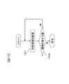
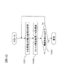
図1に示すのは、本発明の第1の実施の形態による電源装置用状態検知装置の構成図である。本実施形態による状態検知装置は、電気を蓄えて放電を行う蓄電手段101の状態を検知するものである。この状態検知装置は、蓄電手段101を計測して計測値を取得する計測手段102と、蓄電手段101の特性を示す特性情報を記憶するために用いる記憶手段103と、記憶手段103から特性情報を読み出して演算を行う演算手段104と、演算手段104で求めた演算結果を監視して矛盾を検知する矛盾検知手段105と、矛盾検知手段105による矛盾検知結果に応じて記憶手段103に格納された特性情報の補正を行う補正手段106と、演算手段104で求めた結果を外部に出力させるための出力手段107とから成る。
-First embodiment-
FIG. 1 is a configuration diagram of a power supply state detection apparatus according to the first embodiment of the present invention. The state detection device according to the present embodiment detects the state of the power storage means 101 that stores electricity and discharges it. This state detection device includes a
蓄電手段101はリチウムイオン電池、ニッケル水素電池、鉛電池、電気二重層キャパシタなどの蓄電デバイスから成る。蓄電手段101は単セルであっても良いし、単セルを複数組合せたモジュール構造にしても良い。 The power storage means 101 is composed of a power storage device such as a lithium ion battery, a nickel metal hydride battery, a lead battery, or an electric double layer capacitor. The power storage means 101 may be a single cell or a module structure in which a plurality of single cells are combined.
計測手段102は各種センサ類と電気回路から成り、蓄電手段101の状態を検知するために用いられる計測値を取得する。計測手段102が取得する計測値は、蓄電手段101の電圧、電流および温度を少なくとも含む。計測手段102は、これらの計測値を蓄電手段101の外部に設けられた各種センサにより取得した後、電気回路を用いて演算手段104へ出力する。
The
記憶手段103はフラッシュメモリ、EEPROM、または磁気ディスク等のメモリ装置から成る。記憶手段103は、図1のように演算手段104の外部に備えられても良いし、あるいは、演算手段104の内部に備えられたメモリ装置として実現しても良い。記憶手段103は、蓄電手段101の特性情報と、蓄電手段101の状態検知を行うための演算手順とを、それぞれ1種類以上格納する。なお、本実施形態による状態検知装置は、記憶手段103を複数有していても良い。
The storage means 103 includes a memory device such as a flash memory, an EEPROM, or a magnetic disk. The
記憶手段103を状態検知装置から取り外し可能にしても良い。取り外し可能にした場合、記憶手段103を取り替えることによって、特性情報と演算手順とを簡単に更新することができる。また、状態検知装置に取替え可能な記憶手段103を複数設置し、特性情報と演算手順とを別々の記憶手段103に分散して格納しても良い。このようにすれば、特性情報と演算手順を様々な組み合わせにより更新することが可能となる。
The
記憶手段103は、蓄電手段101の内部抵抗値を特性情報として格納している。さらに、蓄電手段101の分極抵抗、充電効率、許容電流、全容量などを特性情報として記憶手段103に格納しても良い。これらの特性情報の内容は、蓄電手段101の特性に応じて予め定められる。なお、特性情報では、充電時と放電時に対してそれぞれ別々の値を設定しても良いし、さらに蓄電手段101の状態、たとえば充電状態や温度などに応じて異なる値を設定しても良い。あるいは、蓄電手段101の状態に関わらず、共通の1つの値を特性情報として設定してもよい。
The storage means 103 stores the internal resistance value of the power storage means 101 as characteristic information. Further, the polarization resistance, charging efficiency, allowable current, total capacity, etc. of the power storage means 101 may be stored in the storage means 103 as characteristic information. The contents of the characteristic information are determined in advance according to the characteristics of the
また記憶手段103は、蓄電手段101の状態検知を行うための演算手順として、蓄電手段101の充電状態を求める演算手順を格納している。さらに、蓄電手段101の許容電流、連続充放電時間、温度制御、過充電、過放電検知などの処理を記憶手段103に格納しても良い。これらの演算手順は、演算手段104によって実行される。
In addition, the
演算手段104はマイクロプロセッサやコンピュータなどから成る。演算手段104は、計測手段102により取得された計測値と、記憶手段103に格納された特性情報とに基づいて、記憶手段103に格納された演算手順に基づく演算を行うことにより、蓄電手段101の状態検知を行う。 The computing means 104 is composed of a microprocessor or a computer. The calculation means 104 performs a calculation based on the calculation procedure stored in the storage means 103 based on the measurement value acquired by the measurement means 102 and the characteristic information stored in the storage means 103, thereby storing the power storage means 101. Detect the state of
矛盾検知手段105は、演算手段104による状態検知の結果を監視して、理論値から外れる矛盾が生じていないか監視を行う。演算手段104で求めた結果が理論値から外れている場合、矛盾検知手段105はその結果を矛盾として検知する。
The
補正手段106は、矛盾検知手段105が検知した理論値から外れる矛盾に応じて、記憶手段103に格納された特性情報を補正する。この補正手段106は、矛盾検知手段105が理論値から外れる矛盾を検知した場合にのみ起動させても良いし、理論値から外れる矛盾の有無に関わらず起動させても良い。矛盾の有無に関わらず補正手段106を起動させる場合、矛盾検知手段105が矛盾を検知した際には所定の補正量で特性情報の補正を行い、理論値から外れる矛盾が無い場合は補正量を0とすれば良い。
The
出力手段107は、イーサネット(登録商標)、CAN、無線LAN、短距離無線通信などにより信号を外部へ出力するためのデバイスや回路から成る。なお、出力手段107は、有線通信と無線通信のどちらで信号を出力しても良い。あるいは、ディスプレイなどの表示装置を出力手段107として用いても良い。この場合、たとえば、計測手段102の計測値、演算手段104による蓄電手段101の状態検知の結果、記憶手段103に格納した特性情報などを出力手段107により出力できる。さらに、これらの時系列的な変化の様子をグラフなどにより表示しても良い。
The
以上説明した状態検知装置の動作フローを図2に示す。演算手段104、矛盾検知手段105および補正手段106は、この動作フローに従ってそれぞれ処理を行う。ステップ200において、演算手段104は、計測手段102により取得された計測値と、記憶手段103に格納された特性情報とに基づいて、蓄電手段101の状態検知を行う。この状態検知の具体的な方法については後述する。
The operation flow of the state detection apparatus described above is shown in FIG. The calculation means 104, the contradiction detection means 105, and the correction means 106 perform processing according to this operation flow. In
ステップ201において、演算手段104は、蓄電手段101が充電中または放電中であるか否かを判定する。蓄電手段101が充電中または放電中である場合はステップ202へ進み、充電中または放電中でない場合はステップ205へ進む。
In
ステップ202において、矛盾検知手段105は、計測手段102により取得された計測値と、演算手段104による状態検知の結果とに基づいて、理論値から外れる矛盾がないか否かを判定する。矛盾があると判定した場合はステップ203へ進み、矛盾がないと判定した場合はステップ205へ進む。
In
ステップ203において、補正手段106は、記憶手段103に格納されている特性情報を補正する。補正された特性情報は、それまでの特性情報に替わって記憶手段103に格納され、特性情報の内容が更新される。
In
ステップ204において、演算手段104は、計測手段102により取得された計測値と、記憶手段103に格納された補正後の特性情報とに基づいて、ステップ200と同様にして蓄電手段101の状態検知を再度行う。
In
ステップ205において、演算手段104は、得られた状態検知の結果を最新情報として更新し、出力手段107へ送信する。演算手段104から状態検知の結果が送信されると、出力手段107は、その結果を前述のようにして外部へ出力する。ステップ205を実行すると、図2の動作フローが完了する。前述した図2の動作フローは、状態検知装置によって予め定められた時間間隔毎に実行されるものであり、これにより、出力手段107は最新の状態検知の結果を送信し続けることができる。
In
なお、矛盾検知手段105及び補正手段106は、それぞれが前述した処理を行う別個のマイクロプロセッサやコンピュータとして実現しても良いし、矛盾検知手段105と補正手段106の処理をまとめて実行する1つのマイクロプロセッサやコンピュータとして実現しても良い。この場合、演算手段104と矛盾検知手段105と補正手段106は情報及び命令のやり取りを行う通信手段で接続される。
The
また、図1において矛盾検知手段105及び補正手段106は演算手段104の外部に設置してあるが、演算手段104により実行される前述した処理内容のプログラムモジュールやサブルーチンとしてそれぞれを実現しても良い。あるいは、前述した矛盾検知手段105と補正手段106の処理を1つにまとめた演算手続きとして実現しても良い。この場合、矛盾検知手段105及び補正手段106は記憶手段103に格納され、演算手段104によって読み出される。
In FIG. 1, the
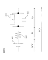
次に、図2のステップ200および204において蓄電手段101の状態検知を行うための演算手順の詳細を説明する。図3は蓄電手段101の等価回路を示す回路図である。図3において、301は蓄電手段101の起電力すなわち開回路電圧(OCV)、302は内部抵抗(R)、303はインピーダンス(Z)、304はキャパシタンス成分(C)である。図3に示すように、蓄電手段101は、インピーダンス303とキャパシタンス成分304の並列接続対、内部抵抗302および起電力301の直列接続で表される。この蓄電手段101に電流Iを印加すると、蓄電手段101の端子間電圧(CCV)は下記(式1)で表される。
CCV=OCV+I・R+Vp (式1)
ここで、Vpは分極電圧であり、ZとCの並列接続対の電圧に相当する。
Next, details of the calculation procedure for detecting the state of the power storage means 101 in
CCV = OCV + I ・ R + Vp (Formula 1)
Here, Vp is a polarization voltage and corresponds to the voltage of a parallel connection pair of Z and C.
OCVはSOC(充電状態)の演算に用いられるが、蓄電手段101が充放電されている状況では、OCVを直接測定することが不可能である。このため、下記(式2)の様にCCVからIRドロップとVpを差し引くことにより、OCVが算出される。
OCV=CCV−IR−Vp (式2)
The OCV is used for the calculation of the SOC (charged state), but it is impossible to directly measure the OCV when the power storage means 101 is charged / discharged. For this reason, OCV is calculated by subtracting IR drop and Vp from CCV as shown in the following (formula 2).
OCV = CCV−IR−Vp (Formula 2)
(式2)において、RとVpは記憶手段103に格納された特性情報から求めることができる。RとVpの値は、蓄電手段101の充電状態や温度などに応じて決定される。一方、電流値Iは計測手段102で取得した計測値から得られる。このIとRとVpを用いて(式2)でOCVを算出することで、予め設定されたOCVとSOCの関係から蓄電手段101のSOC(SOCv)を推定することができる。すなわち、蓄電手段101の起電力(開回路電圧)OCVに基づいて、蓄電手段101の充電状態を示すSOCvが求められる。たとえば図4に示すように、OCVが符号401に示す値であり、OCVとSOCの関係が符号402に示すカーブで表される場合には、符号403に示すようにSOCの値が推定される。
In (Expression 2), R and Vp can be obtained from the characteristic information stored in the storage means 103. The values of R and Vp are determined according to the state of charge of the power storage means 101 and the temperature. On the other hand, the current value I is obtained from the measured value acquired by the measuring means 102. By calculating the OCV using (Equation 2) using I, R, and Vp, the SOC (SOCv) of the power storage means 101 can be estimated from the preset relationship between OCV and SOC. That is, based on the electromotive force (open circuit voltage) OCV of the power storage means 101, the SOCv indicating the state of charge of the power storage means 101 is obtained. For example, as shown in FIG. 4, when OCV is a value indicated by
また、演算手段104は前述した演算手順に加えて、(式3)(式4)に示すSOCの計算も行うものとする。ここで、Iは計測手段102で計測した蓄電手段101に出入りする電流値であり、Qmaxは蓄電手段101の満充電時の容量である。(式4)のWは両SOC(SOCv、SOCi)値の重み付けを行う係数である。それぞれのSOCに発生し得るSOC誤差を予め求め、最もSOC誤差が小さくなるよう最適化した重み付け係数Wが予め記憶手段103に格納される。なお、本重み付け係数Wは、リアルタイムにそれぞれのSOCに発生し得る誤差を求めて誤差が最小となるように演算手段104において決定しても良い。あるいは、蓄電手段101の温度やSOC、蓄電手段101の特性情報、蓄電手段101に出入りする電流値に代表される蓄電手段101の使用状態、計測手段102の異常状態など、これら1つ以上の情報に基づいて重み付け係数Wを決定しても良い。このように、SOCvとSOCiとを誤差が最小となるよう組合せることによって、SOCvよりも高精度な別のSOC(SOCc)を計算することができる。
SOCi=SOC+100×∫Idt/Qmax (式3)
SOCc=W×SOCv+(1−W)×SOCi (式4)
Further, in addition to the above-described calculation procedure, the calculation means 104 also calculates the SOC shown in (Expression 3) and (Expression 4). Here, I is a current value that enters and exits the
SOCi = SOC + 100 × ∫Idt / Qmax (Formula 3)
SOCc = W × SOCv + (1−W) × SOCi (Formula 4)
(式3)において、SOCiは蓄電手段101の積算電流を表す∫Idtに基づいて求められる。(式4)において、SOCcはこのSOCiと、SOCvに基づいて求められる。すなわち、蓄電手段101の充電状態を示すSOCiとSOCcは、いずれも前述のSOCvとは異なる方法か、異なる方法の特徴も組み合わせた蓄電手段101の充電状態の計算結果である。
In (Expression 3), SOCi is obtained based on ∫Idt representing the accumulated current of power storage means 101. In (Expression 4), SOCc is obtained based on this SOCi and SOCv. That is, SOCi and SOCc indicating the state of charge of the
なお、本実施形態において、演算手段104は(式3)によるSOCiから(式4)を用いてSOCcを計算しているが、計測手段102から取得した電流値が高精度な場合、若しくは電流値に含まれる誤差が無視できる条件に限定して処理を行う場合では、(式4)を適用する必要はない。このような場合、単純に(式2)及び図4で説明したSOCvの計算と、(式3)によるSOCiの計算だけでも良いものとする。すなわち、演算手段104は、蓄電手段101の充電状態として、SOCvと、SOCiまたはSOCcと、2種類のSOCを求める。 In the present embodiment, the calculation means 104 calculates SOCc from SOCi according to (Expression 3) using (Expression 4). However, when the current value acquired from the measurement means 102 is highly accurate, or the current value In the case where the processing is performed only on the condition that the error included in can be ignored, it is not necessary to apply (Equation 4). In such a case, the calculation of SOCv described in (Expression 2) and FIG. 4 and the calculation of SOCi according to (Expression 3) may be simply performed. That is, the calculation means 104 obtains SOCv, SOCi or SOCc, and two types of SOC as the state of charge of the power storage means 101.
また、本実施形態においてはSOCiまたはSOCcを用いているが、SOCvとは異なる方法でSOCを計算し、SOCvよりも誤差がより小さくなるようなものであれば、どのような方法でSOCを計算してもよい。 In this embodiment, SOCi or SOCc is used, but SOC is calculated by a method different from SOCv, and SOC is calculated by any method as long as the error is smaller than SOCv. May be.
演算手段104は、以上説明したような演算手順を用いて異なる2種類のSOCを求めることにより、図2のステップ200および204において蓄電手段101の状態検知を行う。こうして行った状態検知の結果は、演算手順104から矛盾検知手段105に送信される。
The calculation means 104 detects the state of the power storage means 101 in
矛盾検知手段105は、演算手順104において上記のような演算手順により蓄電手段101の状態検知の結果として求められた2種類のSOCを監視する。そして、図2のステップ202において、その結果に矛盾が生じているか否かを判定する。以下に矛盾検知手段105が行う矛盾検知の動作を説明する。
The
矛盾検知手段105は、計測手段102で取得した蓄電手段101の計測値のうち電流値を取得する。この電流値が充電を示すとき、SOCは充電した分だけ増加するのが自然である。しかしながら、SOCvの計算で使用する蓄電手段101の特性情報の内部抵抗(R)が、真の蓄電手段101の特性と比較して小さい場合、SOCvは真値と比較して急峻に増加し、その後は真値よりも高い計算結果が得られてしまう。又、放電時ではこれとは逆に、SOCvは真値と比較して急峻に減少し、その後は真値よりも低い計算結果が得られる。矛盾検知手段105はこれを理論値から外れる矛盾として検知する。
The
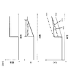
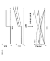
図5を用いて、矛盾検知手段105の詳細な処理内容を、充電時を例にして説明する。ここで、図5の符号501はパルス充電中のSOCv、符号502はSOCcである。前述したように、記憶手段103に特性情報として記憶されている内部抵抗Rの値が真の蓄電手段101の内部抵抗値と比較して小さい場合、蓄電手段101の充電が開始されるとSOCvは急峻に増加し、充電中はそのまま真値よりも大きな値として計算される。一方、SOCcは電流積算によるSOCiとも組合せているため真値に近く、符号501に示すSOCvのように大きな誤差は生じない。これを利用して、矛盾検知手段105は、記憶手段103に格納された特性情報のRが小さ過ぎる場合に発生するSOCv誤差を、符号503に示す基準値を用いて検出する。具体的には、符号502のSOCcに所定の検出閾値Thだけ加算してこれを基準値SOCc_+thとし、充電中にSOCvと基準値SOCc_+thとを比較して、両者が同じかSOCvの方が大きい場合には理論値から外れる矛盾として検出する。すなわち、SOCvがSOCcよりも閾値Th以上大きい場合に、理論値から外れる矛盾が生じたと判断する。
The detailed processing content of the
閾値Thは、計測手段102の計測値に含まれる誤差に基づいて決定することが好ましい。これは、SOCvの誤差が計測手段102の計測値に含まれる誤差によって生じ得る範囲内であれば、記憶手段103に格納したRが小さ過ぎる、または計測手段102による計測値に誤差が含まれているという両方の可能性があるため、矛盾検知手段105はここでのSOCv誤差は許容し、矛盾としては検出しないことが望ましいからである。計測手段102の計測値に含まれる誤差とは、オフセット誤差、ゲイン誤差、量子化誤差、ヒステリシス誤差、温度特性による誤差などである。これら1つ以上の誤差に基づきSOCvに発生するSOC誤差を見積もり、閾値Thとして設定することができる。なお、閾値Thは電流に応じて複数の値を設定しても良いし、蓄電手段101の温度や充電状態、劣化状態などに応じて複数の値を設定しても良い。
The threshold Th is preferably determined based on an error included in the measurement value of the
一方、放電時は、記憶手段103に特性情報として記憶されているRの値が真の蓄電手段101の内部抵抗値と比較して小さい場合、蓄電手段101の放電が開始されると、SOCvは真値と比較して急峻に減少し、その後は真値よりも低い計算結果が得られる。SOCcは電流積算によるSOCiとも組合せているため真値に近く、SOCvのように大きな誤差は生じない。これを利用して、矛盾検知手段105は、記憶手段103に格納された特性情報のRが小さ過ぎる場合に発生するSOCv誤差を検出する。具体的には、SOCcから前述の検出閾値Thを減算してこれを基準値SOCc_-thとし、放電中にSOCvと基準値SOCc_-thとを比較して、両者が同じかSOCvの方が小さい場合には理論値から外れる矛盾として検出する。すなわち、SOCvがSOCcよりも閾値Th以上小さい場合に、理論値から外れる矛盾が生じたと判断する。
On the other hand, at the time of discharging, if the value of R stored as characteristic information in the storage means 103 is small compared to the internal resistance value of the true power storage means 101, when the discharge of the power storage means 101 is started, SOCv is Compared with the true value, it decreases sharply, and thereafter a calculation result lower than the true value is obtained. Since SOCc is also combined with SOCi by current integration, it is close to the true value and does not cause a large error like SOCv. Using this, the
矛盾検知手段105が以上説明したような理論値から外れる矛盾を検知した場合、補正手段106は記憶手段103に格納された特性情報を補正し、補正された特性情報を新たに記憶手段103に格納する。この場合の補正手段106の動作を、図6を用いて説明する。尚、図6中の符号501はパルス充電中のSOCv、符号502はSOCc、符号503はSOCv誤差検出用の基準値であり、それぞれの機能は図5と同様である。図6では内部抵抗Rの変化と、内部抵抗Rの変化に伴うSOCv変化(図6中の符号601)を含めている。
When the
上記のように理論値から外れる矛盾が検知された場合、すなわち蓄電手段101の充電中にSOCvがSOCcよりも閾値Th以上大きい場合、または蓄電手段101の放電中にSOCvがSOCcよりも閾値Th以上小さい場合は、特性情報における内部抵抗Rの値を上げることで解決することができる。従って、補正手段106は補正対象を内部抵抗Rとし、図6に示すように内部抵抗Rを上げる補正を施す。補正された内部抵抗Rは新たな特性情報として記憶手段103に格納され、次回の演算では補正された内部抵抗Rを用いてSOCvは計算される。 When a contradiction deviating from the theoretical value is detected as described above, that is, when SOCv is greater than SOCc by a threshold value Th during charging of the power storage means 101, or during the discharge of the power storage means 101, SOCv is greater than the threshold value Th by SOCc. If it is small, it can be solved by increasing the value of the internal resistance R in the characteristic information. Therefore, the correction means 106 sets the correction target as the internal resistance R, and performs correction to increase the internal resistance R as shown in FIG. The corrected internal resistance R is stored in the storage means 103 as new characteristic information, and SOCv is calculated using the corrected internal resistance R in the next calculation.
補正手段106が特性情報において内部抵抗Rを補正するタイミングは、矛盾検知手段105がSOCv誤差を検出している間全てに適用しても良い。この場合はSOCvを計算している単位時間毎にSOCv誤差が解消するまで補正が繰り返されるため(図6中の符号601はRの補正によりSOCv誤差が解消する様子を示す)、比較的短時間で内部抵抗Rを蓄電手段101の真の特性情報に合うよう最適化することができる。また、計測手段102の計測値に含まれる誤差以外での要因によってSOCv誤差の発生が想定される場合などは、蓄電手段101の充電または放電開始から所定時間を経過した後は特性情報の補正を禁止することで時間的な制限を設けても良い。たとえば、1秒、5秒、10秒、20秒間と限定して特性情報の補正を行うことができる。
The timing at which the correcting
1回の補正における内部抵抗Rの補正量は、1%などの割合に応じた値や、1、0.1、0.01mΩなどの固定値とすることができる。あるいは、SOCvの誤差に応じて内部抵抗Rの補正量を変化させても良い。記憶手段103において内部抵抗Rの値が温度や充電状態などに応じてテーブル状に記憶されている場合は、そのテーブルのうち一つの値のみを補正対象としても良く、テーブル全体を一度に補正しても良い。また、温度に応じたテーブル、充電状態に応じたテーブルなど、電池状態を一つに絞ってテーブル全体を補正することも可能である。
The correction amount of the internal resistance R in one correction can be a value corresponding to a ratio such as 1% or a fixed value such as 1, 0.1, 0.01 mΩ. Alternatively, the correction amount of the internal resistance R may be changed according to the SOCv error. When the value of the internal resistance R is stored in the
次に、前述の場合とは反対に、計測手段102で取得した電流値が充電を示し、演算手段104が実行した状態検知の結果がSOCの減少を示した場合、或いは電流値が放電を示し、演算手段104による状態検知の結果がSOCの増加を示した場合の矛盾検知手段105の動作を説明する。
Next, contrary to the above case, when the current value acquired by the measuring means 102 indicates charging and the result of the state detection executed by the calculating means 104 indicates a decrease in SOC, or the current value indicates discharging. The operation of the
計測手段102で取得した電流値が充電を示すとき、SOCは充電した分だけ増加するのが自然である。しかしながら、記憶手段103に蓄電手段101の特性情報として記憶されている内部抵抗Rの値が、真の蓄電手段101の内部抵抗値と比較して大きい場合、SOCvは真値と比較して逆方向に急峻に変化し、充電中は真値よりも低く、放電中は真値よりも高いSOC計算結果が得られてしまう。矛盾検知手段105はこれを理論値から外れる矛盾として検知する。 When the current value acquired by the measuring means 102 indicates charging, it is natural that the SOC increases by the amount charged. However, when the value of the internal resistance R stored in the storage means 103 as the characteristic information of the power storage means 101 is larger than the internal resistance value of the true power storage means 101, the SOCv is in the reverse direction compared to the true value. As a result, the SOC calculation result is lower than the true value during charging and higher than the true value during discharging. The contradiction detection means 105 detects this as a contradiction that deviates from the theoretical value.
図7を用いて、矛盾検知手段105の詳細な処理内容を、充電時を例にして説明する。ここで、図7の符号701はパルス充電中のSOCv、符号702はSOCcである。前述したように、記憶手段103に特性情報として記憶されている内部抵抗Rの値が真の蓄電手段101の内部抵抗値と比較して大きい場合、蓄電手段101の充電が開始されるとSOCvは急峻に真値とは逆方向に変化し、充電中は真値よりも小さな値として計算され続ける。一方、SOCcは電流積算によるSOCiとも組合せているため真値に近く、符号701に示すSOCvのように大きな誤差は生じない。これを利用して、矛盾検知手段105は、記憶手段103に格納された特性情報のRが大き過ぎる場合に発生するSOCv誤差を、符号703に示す基準値を用いて検出する。具体的には、符号702のSOCcから所定の検出閾値Thを減算してこれを基準値SOCc_-thとし、充電中にSOCvと基準値SOCc_-thとを比較して、両者が同じかSOCvの方が小さい場合には理論値から外れる矛盾として検出する。すなわち、SOCvがSOCcよりも閾値Th以上小さい場合に、理論値から外れる矛盾が生じたと判断する。この検出閾値Thは、前述したように計測手段102の計測値に含まれる誤差に基づいて決定することができる。
The detailed processing contents of the
一方、放電時は、記憶手段103に特性情報として記憶されているRの値が真の蓄電手段101の内部抵抗値と比較して大きい場合、蓄電手段101の放電が開始されるとSOCvは急峻に真値とは逆方向に変化し、放電中はそのまま真値よりも大きな値として計算される。一方、SOCcは電流積算によるSOCiとも組合せているため真値に近く、SOCvのように大きな誤差は生じない。これを利用して、矛盾検知手段105は、記憶手段103に格納された特性情報のRが大き過ぎる場合に発生するSOCv誤差を検出する。具体的には、SOCcに前述の検出閾値Thだけ加算してこれを基準値SOCc_+thとし、放電中にSOCvと基準値SOCc_+thとを比較して、両者が同じかSOCvの方が大きい場合には理論値から外れる矛盾として検出する。すなわち、SOCvがSOCcよりも閾値Th以上大きい場合に、理論値から外れる矛盾が生じたと判断する。
On the other hand, at the time of discharging, if the value of R stored as characteristic information in the storage means 103 is larger than the internal resistance value of the true power storage means 101, the SOCv becomes steep when the discharge of the power storage means 101 is started. It changes in the direction opposite to the true value, and is calculated as a value larger than the true value during discharge. On the other hand, since SOCc is combined with SOCi based on current integration, it is close to the true value and does not cause a large error like SOCv. Using this, the
上記のように理論値から外れる矛盾が検知された場合、すなわち蓄電手段101の充電中にSOCvがSOCcよりも閾値Th以上小さい場合、または蓄電手段101の放電中にSOCvがSOCcよりも閾値Th以上大きい場合は、特性情報における内部抵抗Rの値を下げることで解決することができる。従って、補正手段106は内部抵抗Rを下げる補正を施す。補正された内部抵抗Rは新たな特性情報として記憶手段103に格納され、次回の演算から用いられる。 When a contradiction deviating from the theoretical value as described above is detected, that is, when SOCv is smaller than SOCc by a threshold value Th during charging of the power storage means 101, or during the discharge of the power storage means 101, SOCv is a threshold value Th or more than SOCc. If it is large, it can be solved by lowering the value of the internal resistance R in the characteristic information. Therefore, the correction means 106 performs correction to lower the internal resistance R. The corrected internal resistance R is stored in the storage means 103 as new characteristic information and used from the next calculation.
前述した矛盾検知手段105と補正手段106の動作を、図8を用いて説明する。尚、図8中の符号701、702、703は、図7中のものと同じである。又、符号801はRが大き過ぎる際に発生するSOCv誤差を矛盾検知手段105が検知し、補正手段106が内部抵抗Rを下げる補正を施し、結果としてSOCv誤差が解消する様子を示している。このように、SOCv誤差が基準値以内になるまで補正手段106によりRの補正が繰り返される。前述した内部抵抗Rの値を上げる補正の場合と同様に、特性情報における内部抵抗Rの値を下げる場合も、矛盾検知手段105がSOCv誤差の発生を検知している間全てにおいて行うことができる。あるいは、蓄電手段101の充電または放電開始から所定時間を経過した後は特性情報の補正を禁止してもよい。すなわち、1秒、5秒、10秒、20秒間と限定して補正を行うなど、時間的な制限を設けても良いものである。
The operations of the
表1に、以上説明した矛盾検知手段105が理論値から外れる矛盾を検知する動作と、その矛盾が生じた原因と、その矛盾を解決するために行う補正手段106の動作との関係を示す。このように、Rが小さすぎるときに発生するSOCv誤差と、Rが大きすぎるときに発生するSOCv誤差とを、理論値から外れる矛盾として矛盾検知手段105が検知し、その矛盾内容に応じて補正手段106がRを補正するので、SOCv誤差が少なく、その後のSOCcの計算も更に誤差が小さくすることが可能な状態検知装置を実現できる。更に、充放電の継続中においても矛盾検知手段105による矛盾検知と補正手段106による特性情報の補正処理が可能であるため、記憶手段103に格納された特性情報と蓄電手段101における真の値との間で大きな差があった場合でも、比較的短時間で記憶手段103の特性情報を蓄電手段101における真の値へと収束させることが可能となる。

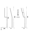
図9を用いて、前述した本実施例における矛盾検知手段105と補正手段106の動作を、充放電パターンの違いに注目して説明する(ここでは例としてRが小さ過ぎる場合を示した)。図9中の符号901はRの補正によって誤差が改善されるSOCvの変化、符号902はSOCc、符号903はSOCv誤差検出用の基準値である。充放電の切り替わりが多い(図9(a))、充放電の切り替わりが少ない(図9(b))両条件において、SOCvがSOCv誤差検出用の基準値から外れる期間に違いはないため、補正手段106の動作に時間の制限等の制約を設けなければ、SOCv誤差が改善、即ち内部抵抗Rが最適値に収束する時間はほぼ同等と考えられる。一般的に、図9(b)のように充放電の切り替わりが少ない、若しくは充放電電流が大きく変化するタイミングが少ないパターンでは、内部抵抗Rの検出タイミングも少ない。検出した内部抵抗Rを複数蓄えて平均化した結果を内部抵抗検出の最終値とする処理を適用した場合では、図9(b)では平均化するのに必要なRの数が蓄えられるまで長い時間が必要となるため、結果として図9(a)とはR最適値が求まる(SOCv誤差が改善する)時間に大きな違いが出る。本発明では、電流変化が少ない条件でも比較的速く内部抵抗Rを収束させることが出来き、前記蓄電手段101の現在の内部抵抗Rを用いて行う各種演算に対して好適である。
The operation of the
また、前述したように、計測手段102の電流センサが極めて高精度で、これに基づき(式3)で計算したSOCiが長期にわたってほぼSOC誤差が含まれない場合、矛盾検知手段105でのSOCcを用いた処理は、全てSOCiを代わりに用いて行うことが可能である。さらに、SOCiの積分計算で生じる累積誤差が無視できるほど短い時間での状態検知装置の動作においても、SOCcの代わりにSOCiを用いることができる。例えば、車両起動時のエンジン始動に伴う蓄電手段101の大電流放電時に対して矛盾検知手段105及び補正手段106の処理を適用する場合、エンジン始動時に伴う大電流放電は短時間で終了するため、電流積算の累積誤差はほぼ無視できるものとして、SOCcに代えてSOCiを適用できる。このようにSOCcに代えてSOCiを用いる場合は、閾値ThをSOCiに加算、減算してSOCvがこれから外れるSOC値を持つ場合は矛盾検知手段105がこれを検知し、補正手段106が特性情報を補正することとなる。
Further, as described above, when the current sensor of the measuring
以上のように、OCVを基準としたSOCvと電流積算を基準としたSOCiの比較によって、SOCvが使用する特性情報を蓄電手段101の真の特性情報に合うよう最適化することができる。矛盾検知手段105と補正手段106の前述した矛盾検知及び特性情報の補正処理は充放電継続中においても可能なため、比較的速く記憶手段103に格納された特性情報を収束させることが可能な電源装置用状態検知装置を実現することができる。
As described above, by comparing the SOCv based on the OCV and the SOCi based on the current integration, the characteristic information used by the SOCv can be optimized to match the true characteristic information of the power storage means 101. Since the above-described contradiction detection and characteristic information correction processing of the
なお、以上説明した実施の形態において、検出閾値Thは全て共通の値としてもよいし、それぞれ異なる値としてもよい。すなわち、特性情報の内部抵抗(R)が真の蓄電手段101の特性と比較して小さい場合に、図5で説明したような充電時の判定に用いる閾値Thと、放電時の判定に用いる閾値Thとは、それぞれ別個に設定することができる。また、特性情報の内部抵抗(R)が真の蓄電手段101の特性と比較して大きい場合に、図7で説明したような充電時の判定に用いる閾値Thと、放電時の判定に用いる閾値Thとについても、それぞれ別個に設定することができる。これら4種類の閾値Thを全て異なる値としてもよい。更には、SOCや温度などの蓄電手段101の状態に応じて検出閾値Thを決定することも可能である。 In the embodiment described above, all the detection threshold values Th may be a common value or may be different values. That is, when the internal resistance (R) of the characteristic information is smaller than the characteristic of the true power storage means 101, the threshold value Th used for the determination at the time of charging and the threshold value used for the determination at the time of discharging as described in FIG. Each Th can be set separately. Further, when the internal resistance (R) of the characteristic information is larger than the characteristic of the true power storage means 101, the threshold value Th used for determination at the time of charging and the threshold value used for determination at the time of discharging as described in FIG. Th can also be set separately. These four types of threshold values Th may all be different values. Furthermore, it is also possible to determine the detection threshold Th according to the state of the power storage means 101 such as SOC and temperature.
−第2の実施の形態−
図10は本発明の第2の実施の形態による電源装置用状態検知装置の構成図である。符号1001に示す部分は、図1に示した第1の実施の形態による電源装置用状態検知装置と同一の構成である。本実施形態による電源装置用状態検知装置は、この状態検知装置1001に加えて、記憶手段103を定期的に監視する劣化判定手段1002をさらに有する。
-Second Embodiment-
FIG. 10 is a configuration diagram of a power supply state detection apparatus according to the second embodiment of the present invention. A portion denoted by
蓄電手段101が劣化した場合の動作を以下に説明する。蓄電手段101が劣化した場合、一般的に蓄電手段101の内部抵抗は上昇する。内部抵抗が上昇した蓄電手段101では、電流Iを印加した場合に生じるIRドロップは初期の蓄電手段101と比較して大きくなる。 The operation when the power storage means 101 is deteriorated will be described below. When the power storage means 101 deteriorates, the internal resistance of the power storage means 101 generally increases. In the power storage means 101 whose internal resistance has increased, the IR drop generated when the current I is applied is larger than that in the initial power storage means 101.
初期の蓄電手段101に対して設定された特性情報を用いて劣化した蓄電手段101のSOC推定を行うと、前述の第1の実施の形態において説明したように、得られる結果に理論値から外れる矛盾が生じる。すなわち、図11に示すように、蓄電手段101が劣化するとSOCvが急峻に変化し、充電中は真値よりも大きなSOC値を示すようになる。放電中はこれとは逆に、真値よりも小さいSOC値を示す(図示せず)。
When the SOC estimation of the deteriorated
矛盾検知手段105は、前述した処理によって発生したSOC誤差を理論値から外れる矛盾として検知する。矛盾として検知されると補正手段106が起動され、前述した処理によって特性情報の補正を行う。この場合、特性情報として記憶手段103に格納された内部抵抗Rの値を上げる補正を行い、その補正結果を新たな特性情報として記憶手段103に格納する。
The contradiction detecting means 105 detects the SOC error generated by the above-described process as a contradiction that deviates from the theoretical value. When it is detected as a contradiction, the correction means 106 is activated and the characteristic information is corrected by the above-described processing. In this case, correction is performed to increase the value of the internal resistance R stored in the
蓄電手段101が劣化すると状態検知装置1001は上記のような動作を行う。さらに蓄電手段101が劣化すると、再度SOCv誤差が検知され、内部抵抗Rの値が補正される。蓄電手段101が劣化するに従って、状態検知装置1001は上記の手順を繰り返す。
When the power storage means 101 deteriorates, the
劣化判定手段1002は、補正手段106による特性情報の補正結果、すなわち補正された内部抵抗Rの値を監視し、その監視結果に基づいて、蓄電手段101が寿命であるか否かを判定する機能を有する。図12に、劣化判定手段1002の動作フローを示す。ステップ1201において劣化判定手段1002は、補正後の特性情報、すなわち本実施形態では補正後の内部抵抗Rの値を監視する。なお、特性情報において内部抵抗Rは、蓄電手段101の充電状態や温度などに応じて様々な値が設定されている。ステップ1202において劣化判定手段1002は、ステップ1201で監視した補正後の内部抵抗Rの中に、予め設定された所定の閾値を超えているものがないかを調べる。閾値を超える内部抵抗Rが存在する場合、劣化判定手段1002は蓄電手段101が寿命であると判定する。この閾値は、たとえば内部抵抗Rの初期値の2倍や3倍などの値として任意に決定することができる。
The
劣化判定手段1002の動作フローの他の例を図13に示す。この場合、記憶手段103は、補正前の初期の特性情報と、別の記憶領域に補正された現在の特性情報とが格納されているものとする。補正手段106が特性情報の補正を行う際は、記憶手段103の初期の特性情報を格納している記憶領域ではなく、記憶手段103内の別の記憶領域に格納している前回の補正結果を更新することで実現する。ステップ1301において劣化判定手段1002は、記憶手段103から初期の特性情報による内部抵抗Rの値と、補正された現在の特性情報による内部抵抗Rの値とを入手する。
Another example of the operation flow of the degradation determination means 1002 is shown in FIG. In this case, it is assumed that the
ステップ1302において劣化判定手段1002は、下記(式5)により、特性情報の上昇率、この場合は蓄電手段101の内部抵抗Rの上昇率を計算する。ここで計算する内部抵抗Rの上昇率は、Rが温度や充電状態などに応じてテーブル状に記憶手段103に格納されている場合は、テーブル全体で比較して上昇率の平均値を求めても良く、現在の温度や充電状態に応じた範囲に限定して比較しても良い。一方、温度や充電状態に関わらず共通のR値が記憶手段103に格納されている場合は、そのRについて(式5)により上昇率を計算する。なお(式5)では、Rの補正結果をRの初期値で除算した値に100を乗算することで、内部抵抗上昇率の初期値を100とし、蓄電手段101が劣化するに従って100から値が上昇するようにしている。しかし、100を乗算せずに、内部抵抗上昇率の初期値が1で蓄電手段101の劣化に応じて1よりも大きな値となるようにしても良い。
R上昇率=100×R補正結果/R初期値 (式5)
In
R rise rate = 100 x R correction result / R initial value (Formula 5)
ステップ1303において劣化判定手段1002は、ステップ1302で計算した内部抵抗Rの上昇率が所定の閾値を超えるか否かを判定する。内部抵抗Rの上昇率が所定の閾値を超える場合、劣化判定手段1002は蓄電手段101が寿命であると判定する。
In
あるいは、ステップ1303において劣化判定手段1002は、ステップ1302で計算した内部抵抗Rの上昇率に基づいて、蓄電手段101が入出力可能な電流または電力を求め、これが所定の閾値を下回る場合に蓄電手段101が寿命であると判定してもよい。この場合の閾値は、蓄電手段101が電源として使用されるシステムにおける所要性能値などに応じて決定することができる。
Alternatively, in
劣化判定手段1002は、前述した処理を行うマイクロプロセッサやコンピュータとして実現できる。図10に示したように、劣化判定手段1002から直接記憶手段103にアクセスして特性情報の補正結果を監視しても良いし、演算手段104が読み出した特性情報を監視しても良い。また、劣化判定手段1002に表示装置を備えれば、劣化の進行状況や寿命と判定された結果をディスプレイなどに表示させることができる。
The
図10の劣化判定手段1002は状態検知装置1001外に設置してあるが、前述した処理内容を行うプログラムモジュールやサブルーチンとして実現しても良い。この場合、劣化判定手段1002は、記憶手段103に格納されて演算手段104で実行される演算手順として実装することができる。劣化判定手段1002が演算手段104により実行されると、劣化判定手段1002は直接記憶手段103を監視するか、記憶手段103に格納される特性情報を読み出し、前述した処理によって特性情報の監視を行う。劣化判定手段1002が判定した蓄電手段101の劣化進行状況や寿命判定結果は、蓄電手段101の状態検知の結果と合わせて演算手段104から出力手段107に送信される。その場合、出力手段107から出力される蓄電手段101の劣化進行状況や寿命判定結果は、出力手段107に接続された他のマイクロプロセッサやコンピュータなどにより表示しても良いし、各種制御に活用しても良い。
Although the
このように、本実施形態では蓄電手段101の劣化に合わせて特性情報が補正され、その補正結果を監視することによって、蓄電手段101の寿命を定量的に判定できる電源装置用状態検知装置が実現可能である。
Thus, in this embodiment, the characteristic information is corrected in accordance with the deterioration of the
−第3の実施の形態−
本発明の第3の実施の形態による電源装置用状態検知装置を以下に説明する。本実施形態による状態検知装置は、図1に示す第1の実施の形態による状態検知装置、または図10に示す第2の実施の形態による状態検知装置において、計測手段102および矛盾検知手段105の動作に変更を加えたものである。
-Third embodiment-
A power supply state detection apparatus according to a third embodiment of the present invention will be described below. The state detection device according to the present embodiment is the same as the state detection device according to the first embodiment shown in FIG. 1 or the state detection device according to the second embodiment shown in FIG. It is a change in behavior.
本実施形態において、計測手段102は、前述したような機能に加えて、状態検知装置が設置されている環境下での周囲温度を計測し、その計測値を矛盾検知手段105へ出力する機能をさらに有する。
In the present embodiment, in addition to the functions described above, the
本実施形態において、矛盾検知手段105は、前述したような動作に加えて、次に説明するような動作をさらに行う。この矛盾検知手段105が行う動作を、図14を用いて説明する。一般的に、計測手段102はある温度(T0)を中心に最も精度が高く、T0から温度が外れるに従って計測誤差が拡大する(T1やT2で誤差が大)。そこで、矛盾検知手段105は、計測手段102が計測した周囲温度を受信し、その周囲温度が所定範囲内であるか否かを判定する。この判定に用いる周囲温度の範囲は、たとえば、図14のデータを参照して前述の動作を行った際に発生する誤差を予め求め、その誤差が許容範囲内の精度となる範囲の温度として決定することができる。こうして周囲温度が所定範囲外であると判定された場合、矛盾検知手段105は第1の実施の形態で説明したような矛盾検知の条件外であると判断し、矛盾検知を禁止してこれを行わないものとする。
In the present embodiment, the
あるいは、記憶手段103に図14の計測手段102の特性を予め記憶しておき、演算手段104がリアルタイムに誤差計算を行って、その計算結果に基づいて矛盾検知手段105を動作させるか否かを判定しても良い。この場合、矛盾検知手段105を動作させるか否かの信号を演算手段104から矛盾検知手段105に送信し、これに応じて矛盾検知手段105が動作する。
Alternatively, the characteristic of the measuring
本実施形態によれば、計測手段102の温度に応じた誤差特性を考慮することによって、高精度に蓄電手段101の状態検知が可能な電源装置用状態検知装置を実現することができる。
According to the present embodiment, it is possible to realize a state detection device for a power supply apparatus that can detect the state of the
−第4の実施の形態−
図15、16は本発明の第4の実施の形態による電源装置用状態検知装置の構成図である。図15に示す状態検知装置は、図1に示す第1の実施の形態による状態検知装置において、演算手段104の処理内容を変更すると共に、新規に充放電制限手段1501を備えている。図16に示す状態検知装置は、図10に示す第2の実施の形態による状態検知装置において、演算手段104の処理内容を変更すると共に、充放電制限手段1501を備えている。なお、図16において、符号1601に示す部分は図15と同じである。いずれの場合においても、演算手段104の処理内容と充放電制限手段1501の動作は同じである。
-Fourth embodiment-
FIGS. 15 and 16 are configuration diagrams of a power supply state detection apparatus according to a fourth embodiment of the present invention. The state detection device shown in FIG. 15 is different from the state detection device according to the first embodiment shown in FIG. 1 in that the processing content of the calculation means 104 is changed and a charge / discharge restriction means 1501 is newly provided. The state detection apparatus shown in FIG. 16 is the same as the state detection apparatus according to the second embodiment shown in FIG. In FIG. 16, the part denoted by
本実施形態において、演算手段104は、前述したような処理に加えて、さらに蓄電手段101が入出力可能な電流値または電力値を求める。一般的に、蓄電手段101の充電状態が高い場合は、蓄電手段101が出力可能な電流値および電力値が大きく、入力可能な電流値および電力値が小さくなる。これとは逆に、蓄電手段101の充電状態が低い場合は、蓄電手段101が出力可能な電流値および電力値が小さく、入力可能な電流値および電力値が大きくなる。演算手段104において求められた蓄電手段101が入出力可能な電流値または電力値は、出力手段107によって外部に設置されたコントローラに出力される。外部のコントローラは、受信した電流値または電力値の範囲内で蓄電手段101が充放電されるように制御を行う。ここでは蓄電手段101が入力可能な電流値を許容充電電流Icmax、電力値を許容充電電力Pcmaxとし、蓄電手段101が出力可能な電流値を許容放電電流Idmax、電力値を許容放電電力Pdmaxとする。
In the present embodiment, in addition to the processing as described above, the
許容充電電流Icmax、許容放電電流Idmaxは以下の式により計算される。
Icmax=(Vmax−OCV)/RZ (式6)
Idmax=(OCV−Vmin)/RZ (式7)
ここで、Vmaxは蓄電手段101の上限電圧、Vminは蓄電手段101の下限電圧、OCVは蓄電手段101の現在の起電力、RZは現在の蓄電手段101における図3のR、Z、Cの等価インピーダンスである。なお、図16に示すように状態検知装置が劣化判定手段1002を備える場合は、蓄電手段101の劣化の進行に応じてRZを更新し、蓄電手段101の性能に合わせた許容充放電電流を計算することが好ましい。図17に、(式6)、(式7)で求められる許容電流の概念図を示す。
The allowable charging current Icmax and the allowable discharging current Idmax are calculated by the following formulas.
Icmax = (Vmax−OCV) / RZ (Formula 6)
Idmax = (OCV−Vmin) / RZ (Formula 7)
Here, Vmax is the upper limit voltage of the power storage means 101, Vmin is the lower limit voltage of the power storage means 101, OCV is the current electromotive force of the power storage means 101, and RZ is the equivalent of R, Z, and C in FIG. Impedance. In the case where the state detection device includes the
(式6)で表される許容充電電流Icmaxに、その許容充電電流Icmaxが得られる時の蓄電手段101の電圧Vchgを乗算することで、下記(式8)に示すように許容充電電力Pcmaxが得られる。また、(式7)で表される許容放電電流Idmaxに、その許容放電電流Idmaxが得られる時の蓄電手段101の電圧Vdisを乗算することで、下記(式9)に示すように許容放電電力Pdmaxが得られる。
Pcmax=Vchg×Icmax (式8)
Pdmax=Vdis×Idmax (式9)
By multiplying the allowable charging current Icmax represented by (Expression 6) by the voltage Vchg of the
Pcmax = Vchg x Icmax (Formula 8)
Pdmax = Vdis × Idmax (Formula 9)
前述のように矛盾検知手段105は、演算手段104により(式2)を用いて求められたSOCvと、(式4)または(式3)を用いて求められたSOCcまたはSOCiとに基づいて、両SOCに所定の閾値Th以上の差が発生した場合に補正手段106を起動させる。これに対して、充放電制限手段1501は、演算手段104が求めたSOCvと、SOCcまたはSOCiとの間の差が、所定の閾値Th´以上であることを検出した場合に、前述した許容充放電電流または許容充放電電力の制限を行うものである。
As described above, the
充放電制限手段1501の詳細な処理内容を、図18を用いて説明する。図18において、符号1801はSOCv、符号1802はSOCcまたはSOCi、符号1803は符号1802に示すSOCcまたはSOCiに閾値Th´を加算したSOCc_+Th´またはSOCi_+Th´をそれぞれ示す。演算手段104において(式6)、(式7)により許容充電電流Icmaxおよび許容放電電流Idmaxがそれぞれ計算される場合、充放電制限手段1501は、蓄電手段101の充電中にSOCvがSOCc_+Th´またはSOCi_+Th´を越えると、符号1804に示す許容充電電流Icmaxを符号1806に示す値に、符号1805に示す許容放電電流Idmaxを符号1807に示す値に、それぞれ制限する。また、蓄電手段101の放電中にSOCvがSOCc_-Th´またはSOCi_-Th´を下回った場合も同様に、符号1804に示す許容充電電流Icmaxを符号1806に示す値に、符号1805に示す許容放電電流Idmaxを符号1807に示す値に、それぞれ制限する。
Detailed processing contents of the charge /
一方、演算手段104において(式8)、(式9)により許容充電電力Pcmaxおよび許容放電電力Pdmaxがそれぞれ計算される場合は、この許容充放電電力を制限することとなる。すなわち、充放電制限手段1501は、蓄電手段101の充電中にSOCvがSOCc_+Th´またはSOCi_+Th´を越えた場合、および蓄電手段101の放電中にSOCvがSOCc_-Th´またはSOCi_-Th´を下回った場合に、許容充電電力Pcmaxおよび許容放電電力Pdmaxを所定の値にそれぞれ制限する。
On the other hand, when the allowable charging power Pcmax and the allowable discharging power Pdmax are respectively calculated by (Equation 8) and (Equation 9) in the
上記の判定において用いる閾値Th´は、矛盾検知手段105が前述の矛盾検知に用いる閾値Thと同じ値か、それ以上の値を設定することが好ましい。SOCvに所定以上の誤差が発生した場合とは、記憶手段103に格納した蓄電手段101の特性情報と、蓄電手段101の真の特性情報との間で大きな差が生じていることを意味する。この特性情報の差から生じる許容充放電電流または許容充放電電力の誤差を計算し、許容される誤差を超える特性情報の差から生じるSOCv誤差を求め、これを閾値Th´としても良い。なお、許容充放電電流または許容充放電電力の制限は、単純に元の値を1/2や1/3としても良いし、あるいは、蓄電手段101が最も劣化して入出力が取れない状況下となった場合の許容充放電電流または許容充放電電力とすることもできる。さらに、SOCvに生じた誤差の量に応じて制限する値を設定することも可能である。
The threshold value Th ′ used in the above determination is preferably set to the same value as or greater than the threshold value Th used by the
以上より、本実施形態によれば、充放電制限手段1501を備えることで、蓄電手段101の特性情報と記憶手段103の特性情報との間で大きな差が発生した場合に、SOCvとSOCcまたはSOCiとを比較することでこれを検出し、的確に許容充放電電流または許容充放電電力を制限することが可能となる。これにより、蓄電手段101を確実に充放電制御するための動作を行うことが可能な電源装置用状態検知装置を実現することができる。
As described above, according to the present embodiment, when the charge /
本発明による電源装置用状態検知装置は、蓄電手段の充電状態を高精度に推定できると共に、定量的に蓄電手段の劣化の進行若しくは寿命を判定できる。更に、確実に蓄電手段を充放電制御するための動作を行うことができる。この電源装置用状態検知装置は、モバイル、UPS、HEV又はEVなどの車両など、幅広い分野に適用可能である。 The state detection device for a power supply device according to the present invention can estimate the state of charge of the power storage means with high accuracy and can quantitatively determine the progress of deterioration or the life of the power storage means. Furthermore, it is possible to reliably perform the operation for charge / discharge control of the power storage means. This power supply state detection device is applicable to a wide range of fields such as mobile, UPS, HEV or EV vehicles.
なお、以上説明した各実施形態と変形例の一つ、もしくは複数を組み合わせることも可能である。変形例をどのように組み合わせることも可能である。 In addition, it is also possible to combine each embodiment described above and one or a plurality of modifications. Any combination of the modified examples is possible.
以上の説明はあくまで一例であり、本発明は上記実施形態の構成に何ら限定されるものではない。 The above description is merely an example, and the present invention is not limited to the configuration of the above embodiment.
101…蓄電手段、102…計測手段、103…記憶手段、104…演算手段、105…矛盾検知手段、106…補正手段、107…出力手段、301…起電力、302…内部抵抗、303…インピーダンス、304…キャパシタンス成分、1002…劣化判定手段、1501…充放電制限手段
DESCRIPTION OF
Claims (15)
前記蓄電手段の特性情報を格納した記憶手段と、
前記計測値と前記記憶手段に格納された前記特性情報とに基づいて、前記蓄電手段の充電状態をそれぞれ示す第一の充電状態および第二の充電状態を異なる方法を用いて求める演算手段と、
前記蓄電手段の充電または放電中に、前記演算手段による充電状態の算出結果を監視し、前記第一の充電状態と前記第二の充電状態との差が所定の閾値以上である場合に矛盾として検知する矛盾検知手段と、
前記蓄電手段の充電または放電中に、前記矛盾検知手段により検知された矛盾に応じて、前記記憶手段に格納されている前記特性情報を補正する補正手段とを備え、
前記閾値は、第一の閾値、第二の閾値、第三の閾値および第四の閾値を含み、
前記矛盾検知手段は、前記蓄電手段の充電中に前記第一の充電状態が前記第二の充電状態よりも前記第一の閾値以上大きい場合、または前記蓄電手段の放電中に前記第一の充電状態が前記第二の充電状態よりも前記第二の閾値以上小さい場合に、前記矛盾として第一の矛盾を検知し、前記蓄電手段の充電中に前記第一の充電状態が前記第二の充電状態よりも前記第三の閾値以上小さい場合、または前記蓄電手段の放電中に前記第一の充電状態が前記第二の充電状態よりも前記第四の閾値以上大きい場合に、前記矛盾として第二の矛盾を検知することを特徴とする電源装置用状態検知装置。 Measuring means for acquiring the current, voltage and temperature of the chargeable / dischargeable power storage means as measured values;
Storage means for storing characteristic information of the power storage means;
Based on the measured value and the characteristic information stored in the storage unit, a calculating unit for obtaining a first charging state and a second charging state respectively indicating a charging state of the power storage unit using different methods;
During charging or discharging of the power storage means, the calculation result of the charging state by the calculating means is monitored, and if the difference between the first charging state and the second charging state is greater than or equal to a predetermined threshold, it is Contradiction detection means to detect,
Correction means for correcting the characteristic information stored in the storage means according to the contradiction detected by the contradiction detection means during charging or discharging of the power storage means ,
The threshold includes a first threshold, a second threshold, a third threshold, and a fourth threshold;
The contradiction detecting unit is configured to detect the first charging when the first charging state is larger than the first charging state than the second charging state during the charging of the power storage unit, or during the discharging of the power storage unit. When the state is smaller than the second charging state by the second threshold or more, the first contradiction is detected as the contradiction, and the first charging state is the second charging during charging of the power storage means. If the first threshold value is smaller than the third threshold value than the second charge state, or if the first charge state is greater than the fourth threshold value than the second charge state during the discharging of the power storage means, A state detection device for a power supply device, characterized in that a contradiction in the power supply is detected.
前記演算手段は、前記蓄電手段の開回路電圧に基づいて前記第一の充電状態を求め、前記蓄電手段の積算電流に基づくか、または前記第一の充電状態と積算電流の重み付け平均に基づいて前記第二の充電状態を求めることを特徴とする電源装置用状態検知装置。 The state detection device for a power supply device according to claim 1,
The calculation means obtains the first charge state based on an open circuit voltage of the power storage means, and is based on an integrated current of the power storage means or based on a weighted average of the first charge state and the integrated current. A state detection device for a power supply device, wherein the second state of charge is obtained.
前記補正手段は、前記矛盾検知手段が前記第一の矛盾を検知した場合は前記特性情報を上げる方向へ補正し、前記矛盾検知手段が前記第二の矛盾を検知した場合は前記特性情報を下げる方向へ補正することを特徴とする電源装置用状態検知装置。 The state detection device for a power supply device according to claim 1 or 2 ,
The correction means corrects the characteristic information in a direction to increase the characteristic information when the contradiction detection means detects the first contradiction, and decreases the characteristic information when the contradiction detection means detects the second contradiction. A state detection device for a power supply device, wherein the state detection device corrects the direction.
前記閾値は、前記計測値に含まれるオフセット誤差、ゲイン誤差、温度特性誤差、量子化誤差およびヒステリシス誤差のいずれか少なくとも一つに基づいて決定されることを特徴とする電源装置用状態検知装置。 In the power unit state detection device according to any one of claims 1 to 3 ,
The state detection device for a power supply device, wherein the threshold is determined based on at least one of an offset error, a gain error, a temperature characteristic error, a quantization error, and a hysteresis error included in the measurement value.
前記補正手段は、前記蓄電手段の充電または放電開始から所定時間を経過した後は、前記特性情報の補正を禁止することを特徴とする電源装置用状態検知装置。 In the state detection apparatus for power supply units as described in any one of Claims 1-4 ,
The power supply device state detection device, wherein the correction unit prohibits the correction of the characteristic information after a predetermined time has elapsed from the start of charging or discharging of the power storage unit.
前記特性情報は前記蓄電手段の内部抵抗値であることを特徴とする電源装置用状態検知装置。 In the state detection device for a power supply device according to any one of claims 1 to 5 ,
The state detection device for a power supply device, wherein the characteristic information is an internal resistance value of the power storage means.
前記補正手段による前記内部抵抗値の補正結果に基づいて、前記蓄電手段が寿命であるか否かを判定する劣化判定手段をさらに備えることを特徴とする電源装置用状態検知装置。 The state detection device for a power supply device according to claim 6 ,
A power supply state detection apparatus, further comprising a deterioration determination unit that determines whether or not the power storage unit has a lifetime based on a correction result of the internal resistance value by the correction unit.
前記劣化判定手段は、前記内部抵抗値の補正結果と前記内部抵抗値の初期値とに基づいて前記内部抵抗値の上昇率を計算し、その計算結果に基づいて前記蓄電手段が寿命であるか否かを判定することを特徴とする電源装置用状態検知装置。 The state detection device for a power supply device according to claim 7 ,
The deterioration determining means calculates the rate of increase of the internal resistance value based on the correction result of the internal resistance value and the initial value of the internal resistance value, and whether the power storage means is at the end of its life based on the calculation result A state detection device for a power supply device, characterized by determining whether or not.
前記劣化判定手段は、前記上昇率が所定値以上となった場合に前記蓄電手段が寿命であると判定することを特徴とする電源装置用状態検知装置。 The state detection device for a power supply device according to claim 8 ,
The deterioration determination unit determines that the power storage unit has a life when the rate of increase is equal to or greater than a predetermined value.
前記劣化判定手段は、前記上昇率に基づいて前記蓄電池が入出力可能な電流または電力を求め、これが所定の所要性能値を下回る場合に前記蓄電手段が寿命であると判定することを特徴とする電源装置用状態検知装置。 The state detection device for a power supply device according to claim 8 ,
The deterioration determining means obtains a current or power that can be input / output by the storage battery based on the rate of increase, and determines that the power storage means is at the end of life when it falls below a predetermined required performance value. A state detection device for power supplies.
前記計測手段は、前記計測値として周囲温度をさらに取得し、
前記矛盾検知手段は、前記周囲温度が所定範囲外である場合は、前記矛盾の検知を禁止することを特徴とする電源装置用状態検知装置。 In the state detection apparatus for power supplies as described in any one of Claims 1-10 ,
The measurement means further acquires an ambient temperature as the measurement value,
The contradiction detection means prohibits the detection of the contradiction when the ambient temperature is outside a predetermined range.
前記演算手段は、前記蓄電手段の状態検知を行うと共に前記蓄電手段が入出力可能な電流値または電力値を求め、
前記演算手段により求められた電流値または電力値を出力する出力手段と、
前記蓄電手段の充電または放電中に、前記演算手段による状態検知の結果が所定の条件を満たす場合に、前記出力手段により出力される電流値または電力値を制限する充放電制限手段とをさらに備えることを特徴とする電源装置用状態検知装置。 In the power unit state detection device according to any one of claims 1 to 11 ,
The computing means detects the state of the power storage means and obtains a current value or power value that can be input / output by the power storage means,
Output means for outputting the current value or power value obtained by the computing means;
Charge / discharge limiting means for limiting the current value or power value output by the output means when the result of state detection by the calculation means satisfies a predetermined condition during charging or discharging of the power storage means. A state detection device for a power supply device.
前記蓄電手段の特性情報を格納した記憶手段と、
前記計測値と前記記憶手段に格納された前記特性情報とに基づいて、前記蓄電手段の充電状態をそれぞれ示す第一の充電状態および第二の充電状態を異なる方法を用いて求めると共に前記蓄電手段が入出力可能な電流値または電力値を求める演算手段と、
前記演算手段により求められた電流値または電力値を出力する出力手段と、
前記蓄電手段の充電または放電中に前記第一の充電状態と前記第二の充電状態との差が所定の閾値以上である場合に、前記出力手段により出力される電流値または電力値を制限する充放電制限手段とを備えることを特徴とする電源装置用状態検知装置。 Measuring means for acquiring the current, voltage and temperature of the chargeable / dischargeable power storage means as measured values;
Storage means for storing characteristic information of the power storage means;
Based on the measured value and the characteristic information stored in the storage unit, the first charging state and the second charging state respectively indicating the charging state of the power storage unit are obtained using different methods, and the power storage unit Calculating means for obtaining a current value or a power value that can be input / output;
Output means for outputting the current value or power value obtained by the computing means;
Limiting the current value or power value output by the output means when the difference between the first charge state and the second charge state is greater than or equal to a predetermined threshold during charging or discharging of the power storage means A state detection device for a power supply device comprising charge / discharge limiting means.
前記蓄電手段の特性情報を格納した記憶手段と、Storage means for storing characteristic information of the power storage means;
前記計測値と前記記憶手段に格納された前記特性情報とに基づいて、前記蓄電手段の充電状態をそれぞれ示す第一の充電状態および第二の充電状態を異なる方法を用いて求める演算手段と、Based on the measured value and the characteristic information stored in the storage unit, a calculating unit for obtaining a first charging state and a second charging state respectively indicating a charging state of the power storage unit using different methods;
前記蓄電手段の充電または放電中に、前記演算手段による充電状態の算出結果を監視し、前記第一の充電状態と前記第二の充電状態との差が所定の閾値以上である場合に矛盾として検知する矛盾検知手段と、During charging or discharging of the power storage means, the calculation result of the charging state by the calculating means is monitored, and if the difference between the first charging state and the second charging state is greater than or equal to a predetermined threshold, it is Contradiction detection means to detect,
前記蓄電手段の充電または放電中に、前記矛盾検知手段により検知された矛盾に応じて、前記記憶手段に格納されている前記特性情報を補正する補正手段とを備え、Correction means for correcting the characteristic information stored in the storage means according to the contradiction detected by the contradiction detection means during charging or discharging of the power storage means,
前記補正手段は、前記蓄電手段の充電または放電開始から所定時間を経過した後は、前記特性情報の補正を禁止することを特徴とする電源装置用状態検知装置。The power supply device state detection device, wherein the correction unit prohibits the correction of the characteristic information after a predetermined time has elapsed from the start of charging or discharging of the power storage unit.
前記蓄電手段の内部抵抗値を前記蓄電手段の特性情報として格納した記憶手段と、Storage means for storing the internal resistance value of the power storage means as characteristic information of the power storage means;
前記計測値と前記記憶手段に格納された前記特性情報とに基づいて、前記蓄電手段の充電状態をそれぞれ示す第一の充電状態および第二の充電状態を異なる方法を用いて求める演算手段と、Based on the measured value and the characteristic information stored in the storage unit, a calculating unit for obtaining a first charging state and a second charging state respectively indicating a charging state of the power storage unit using different methods;
前記蓄電手段の充電または放電中に、前記演算手段による充電状態の算出結果を監視し、前記第一の充電状態と前記第二の充電状態との差が所定の閾値以上である場合に矛盾として検知する矛盾検知手段と、During charging or discharging of the power storage means, the calculation result of the charging state by the calculating means is monitored, and if the difference between the first charging state and the second charging state is greater than or equal to a predetermined threshold, it is Contradiction detection means to detect,
前記蓄電手段の充電または放電中に、前記矛盾検知手段により検知された矛盾に応じて、前記記憶手段に前記特性情報として格納されている前記内部抵抗値を補正する補正手段と、Correction means for correcting the internal resistance value stored as the characteristic information in the storage means according to the contradiction detected by the contradiction detection means during charging or discharging of the power storage means;
前記補正手段による前記内部抵抗値の補正結果に基づいて、前記蓄電手段が寿命であるか否かを判定する劣化判定手段とを備え、Deterioration determining means for determining whether or not the power storage means has a lifetime based on a correction result of the internal resistance value by the correction means;
前記劣化判定手段は、前記内部抵抗値の補正結果と前記内部抵抗値の初期値とに基づいて前記内部抵抗値の上昇率を計算し、計算した前記上昇率に基づいて前記蓄電池が入出力可能な電流または電力を求め、これが所定の所要性能値を下回る場合に前記蓄電手段が寿命であると判定することを特徴とする電源装置用状態検知装置。The deterioration determining means calculates an increase rate of the internal resistance value based on the correction result of the internal resistance value and an initial value of the internal resistance value, and the storage battery can input / output based on the calculated increase rate A state detecting device for a power supply device, characterized in that a current or electric power is obtained and the power storage means is determined to have a life when it is below a predetermined required performance value.
Priority Applications (2)
| Application Number | Priority Date | Filing Date | Title |
|---|---|---|---|
| JP2009258894A JP5439126B2 (en) | 2009-03-31 | 2009-11-12 | Status detector for power supply |
| US12/750,279 US8466708B2 (en) | 2009-03-31 | 2010-03-30 | State detection device for power supply system |
Applications Claiming Priority (3)
| Application Number | Priority Date | Filing Date | Title |
|---|---|---|---|
| JP2009087007 | 2009-03-31 | ||
| JP2009087007 | 2009-03-31 | ||
| JP2009258894A JP5439126B2 (en) | 2009-03-31 | 2009-11-12 | Status detector for power supply |
Publications (3)
| Publication Number | Publication Date |
|---|---|
| JP2010256323A JP2010256323A (en) | 2010-11-11 |
| JP2010256323A5 JP2010256323A5 (en) | 2012-05-10 |
| JP5439126B2 true JP5439126B2 (en) | 2014-03-12 |
Family
ID=42783361
Family Applications (1)
| Application Number | Title | Priority Date | Filing Date |
|---|---|---|---|
| JP2009258894A Active JP5439126B2 (en) | 2009-03-31 | 2009-11-12 | Status detector for power supply |
Country Status (2)
| Country | Link |
|---|---|
| US (1) | US8466708B2 (en) |
| JP (1) | JP5439126B2 (en) |
Cited By (1)
| Publication number | Priority date | Publication date | Assignee | Title |
|---|---|---|---|---|
| WO2021131184A1 (en) | 2019-12-26 | 2021-07-01 | ビークルエナジージャパン株式会社 | Battery control device and battery system |
Families Citing this family (35)
| Publication number | Priority date | Publication date | Assignee | Title |
|---|---|---|---|---|
| DE102010001529A1 (en) * | 2010-02-03 | 2011-08-04 | SB LiMotive Company Ltd., Kyonggi | Adaptive method for determining the performance parameters of a battery |
| US9067584B2 (en) | 2011-01-27 | 2015-06-30 | Toyota Jidosha Kabushiki Kaisha | Vehicle and control method for vehicle |
| EP2669129B1 (en) * | 2011-01-27 | 2014-10-08 | Toyota Jidosha Kabushiki Kaisha | Vehicle, and vehicle control method |
| US9216726B2 (en) | 2011-01-27 | 2015-12-22 | Toyota Jidosha Kabushiki Kaisha | Vehicle and control method for vehicle |
| JP5517986B2 (en) * | 2011-03-30 | 2014-06-11 | 三菱重工業株式会社 | Battery system |
| WO2012140762A1 (en) * | 2011-04-14 | 2012-10-18 | トヨタ自動車株式会社 | Hybrid vehicle and output control method for electric power storage device installed therein |
| JP2012247339A (en) | 2011-05-30 | 2012-12-13 | Renesas Electronics Corp | Semiconductor integrated circuit and operation method therefor |
| US9641011B2 (en) | 2011-06-10 | 2017-05-02 | Hitachi Automotive Systems, Ltd. | Battery control device adapting the battery current limit by decreasing the stored current limit by comparing it with the measured battery current |
| DE102011055231A1 (en) | 2011-11-10 | 2013-05-16 | Evonik Industries Ag | Method of providing control power |
| DE102011055229A1 (en) * | 2011-11-10 | 2013-05-16 | Evonik Degussa Gmbh | Method for providing control power with an energy storage using tolerances in determining the frequency deviation |
| KR101863036B1 (en) * | 2011-11-30 | 2018-06-01 | 주식회사 실리콘웍스 | Method for estimating the state of charge of battery and battery management system |
| JP5819443B2 (en) * | 2011-12-22 | 2015-11-24 | 日立オートモティブシステムズ株式会社 | Battery control device, battery system |
| JP5821669B2 (en) * | 2012-02-01 | 2015-11-24 | トヨタ自動車株式会社 | Estimation apparatus, estimation method, and control method |
| JP5863603B2 (en) * | 2012-08-24 | 2016-02-16 | 日立オートモティブシステムズ株式会社 | Battery state estimation device, battery control device, battery system, battery state estimation method |
| US20140095089A1 (en) * | 2012-10-02 | 2014-04-03 | Zhijian James Wu | System and method for estimated battery state of charge |
| KR101547005B1 (en) * | 2012-10-26 | 2015-08-24 | 주식회사 엘지화학 | Apparatus and method for estimating state of charging of battery |
| WO2014115294A1 (en) * | 2013-01-25 | 2014-07-31 | 日立ビークルエナジー株式会社 | Battery control device, battery system |
| JP6097599B2 (en) * | 2013-03-07 | 2017-03-15 | 古河電気工業株式会社 | Secondary battery state detection method and state detection device |
| EP3002597B1 (en) | 2013-05-23 | 2020-09-16 | Vehicle Energy Japan Inc. | Battery control device |
| US20150042267A1 (en) * | 2013-08-12 | 2015-02-12 | O2Micro Inc. | System and Method for Controlling a Battery |
| CN103852733B (en) * | 2014-02-17 | 2017-01-18 | 上海大学 | LED power supply performance analysis device and method |
| JP6300567B2 (en) * | 2014-02-24 | 2018-03-28 | 日立オートモティブシステムズ株式会社 | Secondary battery system |
| CN104062601B (en) * | 2014-06-09 | 2016-09-14 | 青岛东方循环能源有限公司 | A kind of microwave power supply trouble-shooter |
| JP6615011B2 (en) * | 2016-03-09 | 2019-12-04 | 日立オートモティブシステムズ株式会社 | Battery management system, battery system and hybrid vehicle control system |
| DE112017001422B4 (en) | 2016-05-12 | 2019-03-21 | Hitachi Automotive Systems, Ltd. | Battery state estimator |
| JP6776904B2 (en) * | 2017-01-13 | 2020-10-28 | 株式会社デンソー | Battery pack and power system |
| WO2018162023A2 (en) * | 2017-03-06 | 2018-09-13 | Volvo Truck Corporation | A battery state of power estimation method and a battery state monitoring system |
| JP7067549B2 (en) | 2017-03-31 | 2022-05-16 | 株式会社Gsユアサ | Power storage element management device and power storage element management method |
| KR102515606B1 (en) * | 2017-10-31 | 2023-03-28 | 삼성에스디아이 주식회사 | Method, battery pack, and electronic device for displaying battery charge capacity |
| CN112840220A (en) * | 2018-10-12 | 2021-05-25 | 日本汽车能源株式会社 | Battery control device |
| CN109212434A (en) * | 2018-11-13 | 2019-01-15 | 乐山有研稀土新材料有限公司 | A kind of high-frequency direct-current switch power supply current-voltage-humiture monitoring device |
| JP7346034B2 (en) * | 2019-02-01 | 2023-09-19 | 株式会社東芝 | Storage battery management device and method |
| KR102140011B1 (en) * | 2019-10-31 | 2020-07-31 | 국민대학교 산학협력단 | Method for managing battery and battery management system |
| CN111044909B (en) * | 2019-12-31 | 2022-02-08 | 北京理工大学 | Battery state prediction method and device |
| JPWO2022255480A1 (en) * | 2021-06-04 | 2022-12-08 |
Family Cites Families (10)
| Publication number | Priority date | Publication date | Assignee | Title |
|---|---|---|---|---|
| JP3879278B2 (en) * | 1998-11-10 | 2007-02-07 | 日産自動車株式会社 | Charge amount calculation method and charge amount calculation device for hybrid vehicle |
| JP4144116B2 (en) * | 1998-11-25 | 2008-09-03 | トヨタ自動車株式会社 | Battery charge state detection device |
| JP2000215923A (en) * | 1999-01-25 | 2000-08-04 | Matsushita Electric Ind Co Ltd | Battery degradation judging device |
| JP2001136666A (en) * | 1999-11-09 | 2001-05-18 | Toyota Motor Corp | Battery controller |
| JP3975738B2 (en) | 2001-12-10 | 2007-09-12 | トヨタ自動車株式会社 | Storage battery status detection device |
| JP4157317B2 (en) | 2002-04-10 | 2008-10-01 | 株式会社日立製作所 | Status detection device and various devices using the same |
| JP4200956B2 (en) * | 2004-09-09 | 2008-12-24 | トヨタ自動車株式会社 | Battery control device for hybrid vehicle, battery control method for hybrid vehicle, and hybrid vehicle |
| JP4767558B2 (en) * | 2005-03-07 | 2011-09-07 | 日立ビークルエナジー株式会社 | Power supply state detection device, power supply device, and initial characteristic extraction device used for power supply device |
| JP4745879B2 (en) * | 2006-04-06 | 2011-08-10 | 日立ビークルエナジー株式会社 | Hybrid vehicle control system, hybrid vehicle control method, and vehicle storage battery control system |
| JP4997994B2 (en) * | 2007-01-31 | 2012-08-15 | 富士通株式会社 | Battery remaining capacity prediction device |
-
2009
- 2009-11-12 JP JP2009258894A patent/JP5439126B2/en active Active
-
2010
- 2010-03-30 US US12/750,279 patent/US8466708B2/en active Active
Cited By (1)
| Publication number | Priority date | Publication date | Assignee | Title |
|---|---|---|---|---|
| WO2021131184A1 (en) | 2019-12-26 | 2021-07-01 | ビークルエナジージャパン株式会社 | Battery control device and battery system |
Also Published As
| Publication number | Publication date |
|---|---|
| US8466708B2 (en) | 2013-06-18 |
| JP2010256323A (en) | 2010-11-11 |
| US20100244886A1 (en) | 2010-09-30 |
Similar Documents
| Publication | Publication Date | Title |
|---|---|---|
| JP5439126B2 (en) | Status detector for power supply | |
| KR101461681B1 (en) | Battery charge indication methods, battery charge monitoring devices, rechargeable batteries, and articles of manufacture | |
| EP3002597B1 (en) | Battery control device | |
| JP6734784B2 (en) | How to estimate battery health | |
| US8996324B2 (en) | Battery-state monitoring apparatus | |
| JP6714838B2 (en) | State estimation device and state estimation method | |
| US8779729B2 (en) | Electric storage device monitor | |
| JP5397679B2 (en) | Secondary battery deterioration diagnosis method and secondary battery deterioration diagnosis device | |
| EP2553483B1 (en) | Monitoring state of charge of a battery system | |
| US10845417B2 (en) | Battery state estimation device, battery control device, battery system, battery state estimation method | |
| US8643331B1 (en) | Enhanced voltage-based fuel gauges and methods | |
| CN106662620B (en) | Battery state detection device, secondary battery system, storage medium, and battery state detection method | |
| JP6155830B2 (en) | State estimation device and state estimation method | |
| CN106257737B (en) | State estimation device and state estimation method | |
| WO2016009757A1 (en) | Battery state detection device, secondary battery system, program product, and battery state detection method | |
| JP2017122622A (en) | State estimation device and state estimation method | |
| KR20140052839A (en) | Charge state detecting apparatus | |
| JP6867478B2 (en) | Battery control and vehicle system | |
| JPWO2017169088A1 (en) | Lithium ion secondary battery life estimation device | |
| JP6171128B2 (en) | Battery control system, vehicle control system | |
| JP2003068369A (en) | Detecting method of total capacity of secondary battery and detector of total capacity | |
| EP4130768A1 (en) | Method and apparatus for calculating relative state-of-charge of battery | |
| JP7169917B2 (en) | SECONDARY BATTERY CONTROL DEVICE AND SECONDARY BATTERY CONTROL METHOD | |
| JP6895537B2 (en) | Battery state estimator | |
| JP2023152320A (en) | Power unit and battery state estimation method |
Legal Events
| Date | Code | Title | Description |
|---|---|---|---|
| A521 | Request for written amendment filed |
Free format text: JAPANESE INTERMEDIATE CODE: A523 Effective date: 20120314 |
|
| A621 | Written request for application examination |
Free format text: JAPANESE INTERMEDIATE CODE: A621 Effective date: 20120314 |
|
| A977 | Report on retrieval |
Free format text: JAPANESE INTERMEDIATE CODE: A971007 Effective date: 20130712 |
|
| A131 | Notification of reasons for refusal |
Free format text: JAPANESE INTERMEDIATE CODE: A131 Effective date: 20130723 |
|
| A521 | Request for written amendment filed |
Free format text: JAPANESE INTERMEDIATE CODE: A523 Effective date: 20130924 |
|
| TRDD | Decision of grant or rejection written | ||
| A01 | Written decision to grant a patent or to grant a registration (utility model) |
Free format text: JAPANESE INTERMEDIATE CODE: A01 Effective date: 20131119 |
|
| A61 | First payment of annual fees (during grant procedure) |
Free format text: JAPANESE INTERMEDIATE CODE: A61 Effective date: 20131216 |
|
| R150 | Certificate of patent or registration of utility model |
Ref document number: 5439126 Country of ref document: JP Free format text: JAPANESE INTERMEDIATE CODE: R150 Free format text: JAPANESE INTERMEDIATE CODE: R150 |
|
| S111 | Request for change of ownership or part of ownership |
Free format text: JAPANESE INTERMEDIATE CODE: R313115 |
|
| R350 | Written notification of registration of transfer |
Free format text: JAPANESE INTERMEDIATE CODE: R350 |
|
| R250 | Receipt of annual fees |
Free format text: JAPANESE INTERMEDIATE CODE: R250 |
|
| S111 | Request for change of ownership or part of ownership |
Free format text: JAPANESE INTERMEDIATE CODE: R313117 |
|
| S111 | Request for change of ownership or part of ownership |
Free format text: JAPANESE INTERMEDIATE CODE: R313111 |
|
| R350 | Written notification of registration of transfer |
Free format text: JAPANESE INTERMEDIATE CODE: R350 |
|
| R350 | Written notification of registration of transfer |
Free format text: JAPANESE INTERMEDIATE CODE: R350 |
|
| R250 | Receipt of annual fees |
Free format text: JAPANESE INTERMEDIATE CODE: R250 |
|
| R250 | Receipt of annual fees |
Free format text: JAPANESE INTERMEDIATE CODE: R250 |
|
| R250 | Receipt of annual fees |
Free format text: JAPANESE INTERMEDIATE CODE: R250 |
|
| R250 | Receipt of annual fees |
Free format text: JAPANESE INTERMEDIATE CODE: R250 |